checkpoint queue详解相克军配套视频
Check Point教程
Check point防火墙基本操作手册CheckPoint(中国)TEL:(86)10 8419 3348 FAX:(86)10 8419 3399©2010 Check Point Software Technologies Ltd. All rights reserved.Classification:目录目录 (2)防火墙架构 (3)防火墙的Web管理 (3)配置IP: (4)配置DNS和Host: (5)配置路由: (5)通过防火墙的管理客户端管理 (5)添加防火墙 (7)添加策略步骤 (10)IP节点添加 (10)添加网段 (11)IPS的配置 (13)更新IPS库 (14)新建IPS动作库 (14)应用控制 (16)更新数据库 (16)添加应用控制策略 (17)App Wike (18)自定义添加应用 (18)QOS配置 (20)Qos策略的添加 (20)日志工具的使用 (20)筛选日志 (21)临时拦截可以连接 (22)©2010 Check Point Software Technologies Ltd. All rights reserved.Classification:©2010 Check Point Software Technologies Ltd. All rights reserved.Classification:防火墙架构Check point 防火墙的管理是通过一个三层架构来实现的。
首先我们可以在任意的机器上安装防火墙客户端控制台,然后利用控制台的图形化界面登录check point 的管理服务器,定义出各个网络对象,定义企业各条策略,最后下发到防火墙执行模块。
具体实现过程见图示:防火墙的Web 管理首先打开Web 管理界面,出现登录界面:登陆后的界面设备的Web界面只能配置设备的IP地址,网关,DNS和路由。
还可以针对设备的事件,SNMP监控,代理等信息。
Check Point 统一安全架构

2
Check Point – 安全领域的全球领导者
市场领先地位
• • •
成立于1993年 全球防火墙/VPN 的市场领先厂商* 全部财富100强企业都采用Check Point的产品;财 富500强企业中,有98%是我们的客户
财务实
• 2006年的营业额达到5.75亿美元 • 总市值为54 亿美元(纳斯达克股票代码: CHKP • 现金储备多达16.5亿美元
4x 10/100/1000 Mbps copper or 4 x 1000 Mbps fiber
8x 10/100/1000 Mbps copper or 8 x 1000 Mbps fiber
8x 10/100/1000 Mbps copper or 8 x 1000 Mbps fiber
IT认证部落
puresecurity
11
CheckPoint UTM-1 功能特征
市场上最佳的防火墙
VoIP Instant Msg HTTP
standard
SQL E-mail FTP P2P
standard
VPN (站点对站点,远程访问) 防病毒 (在网关层面) 入侵防御 URL 过滤* 防间谍软件 Web 应用防火墙 SSL VPN IT认证部落
13
二、内部安全&IPS产品线
内网安全网关
SMART集中管理* SmartDefense 统一升 入侵防御 智能蠕虫防范系统 网络区域隔离 LAN 协议保护 终端安全协同控制 终端安全协同控制*
InterSpect 210, 210N, 410, 610, 610F
CheckPoint IPS-1 IPS-1 Sensor 50,200,500 IPS-1 Power Sensor 1000,2000
Vised_manual
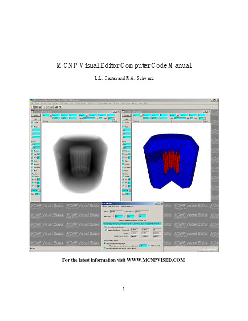
MCNP Visual Editor Computer Code ManualL.L. Carter and R.A. SchwarzFor the latest information visit 1Table of Contents1.0 INTRODUCTION (5)1.1 I NSTALLATION N OTES (5)1.2 P ROGRAM B ACKGROUND (6)2.0 BEGINNING AN INTERACTIVE EDITING SESSION (7)2.1 I MPORTANT F ILES I N T HE V ISUAL E DITOR (8)2.2 T HE M AIN M ENU F UNCTIONS (9)2.3 R EADING A ND W RITING C ELL C ARDS (10)3.0 PLOTTING AND CHANGING PLOT PARAMETERS (11)3.1 U PDATE (12)3.2 L AST B UTTON (12)3.3 Z OOM C HECK B OX (12)3.4 O RIGIN C HECK B OX (12)3.5 C HANGING THE E XTENTS (13)3.6 R EFRESH C HECK B OX (13)3.7 T HE S URFACE AND C ELL C HECK B OX (13)3.8 C OLOR C HECK B OX (13)3.9 F ACETS C HECK B OX (13)3.10 WW M ESH C HECK B OX (13)3.11 R ECT C HECK B OX (14)3.12 P LOT R OTATION O PTIONS (14)3.13 S CALES C HECK B OX (14)3.14 R ES T EXT B OX (14)3.15 C HANGING THE B ASIS (14)3.16 V IEWING G LOBAL/L OCAL C OORDINATES (14)3.17 S ETTING C ELL L ABELS (14)3.18 L EVEL P ULLDOWN M ENU (15)4.0 THE SURFACE WINDOW (16)4.1 C REATING A S URFACE (16)4.2 S CANNING A S URFACE (16)4.3 D ELETING A S URFACE (17)4.4 E DITING A S URFACE (17)4.5 H IDING AND S HOWING S URFACES (17)4.6 S URFACE C OMMENTS (17)4.7 E NTERING S URFACE D IMENSIONS IN I NCHES (17)4.8 S URFACE D ISTANCE (18)4.9 S URFACE D ELTA (18)4.10 M ACROBODY S URFACES (18)5.0 THE CELL WINDOW (19)5.1 C REATING A C ELL (19)5.2 D ISCUSSION O F C ELL P ASTE A ND C UT O PERATIONS (20)25.4 C REATING A C ELL WITH U NIVERSES (22)5.6 U SING U NDO (23)5.7 R EGISTER (23)5.8 S CANNING A C ELL (23)5.9 D ELETING A C ELL (23)5.10 E DITING A C ELL (23)5.11 C REATE LIKE (24)Y OU CAN USE THE “C REATE LIKE” MODE TO CREATE A NEW CELL SIMILAR TO AN EXISTING CELL.A COMMON APPLICATION OF THIS IS TO CREATE A NEW CELL LIKE AN CELL THAT ALREADY EXISTS, BUT WITH A TRANSFORMATION (24)5.12 H IDING AND S HOWING C ELLS (24)5.13 C ELL C OMMENTS (24)5.14 S PLITTING A CELL (25)5.15 C REATING A S QUARE L ATTICE (27)5.16 C REATING A H EXAGONAL L ATTICE (28)5.17 S PECIAL H EX L ATTICE D ISPLAY O PTIONS (29)6.0 MATERIALS (30)6.1 C REATING A M ATERIAL (30)6.2 S CANNING A M ATERIAL (31)6.3 D ELETE A M ATERIAL (31)6.4 E DIT A M ATERIAL (31)6.5 T HE V ISED.DEFAULTS F ILE (31)6.6 M ATERIAL L IBRARY (33)6.7 M ATERIAL O PTIONS (33)7.0 IMPORTANCES (34)7.1 S ETTING C ELL I MPORTANCES (34)7.2 U SING A S CALE F ACTOR (34)7.3 U SING A G EOMETRIC F ACTOR (34)7.4 T HE I MPORTANCE D ISPLAY (35)7.5 T RUNCATING IMPORTANCES (35)8.0 TRANSFORMATIONS (36)9.0 RUN (37)10.0 PARTICLE DISPLAY (39)10.1 SDEF S OURCE P LOTTING (39)10.2 KCODE S OURCE P LOTTING (40)10.3 P ARTICLE T RACK P LOTTING (40)10.4 S ETTING P OINT C OLOR AND S IZE (41)10.5 S ETTING E NERGY OR W EIGHT R ANGES (41)10.6 P ROBLEMS G ENERATING P ARTICLE T RACKS (41)11.0 TALLY PLOTS (43)313.0 3D VIEW (47)13.1 3D C OLOR P LOTS (47)13.2 3D U PDATE THE P LOT B ASIS (48)13.3 C OLOR BY C ELL/S URFACE (48)13.4 D RAW L INES A ROUND C ELLS (48)13.5 C OLOR C ELLS BY M ATERIAL (48)13.6 3D S HADING (48)13.7 D ISTANCE S HADING (48)13.8 P OINT/P LANE S OURCE T YPE (48)13.9 S HOW THE P LOT P LANE (49)13.10 H IDE/S HOW C OOKIE C UTTERS (49)13.11 P LOT TO THE O UTSIDE W ORLD/P LOT P LANE (49)13.12 P LOT R ESOLUTION (49)13.13 3D R ADIOGRAPHIC P LOTS (49)14.0 READ AGAIN (51)15.0 BACKUP INP (51)16.0 PROBLEM REPORTING (51)17.0 REFERENCES (52)APPENDIX A (53)41.0 IntroductionThe Monte Carlo N-Particle (MCNP) computer code is a particle transport code with powerful three dimensional geometry and source modeling capabilities that can be applied to reactor physics, shielding, criticality, environmental nuclear waste cleanup, medical imaging, and numerous other related areas.Creating a MCNP input file with a line editor is both tedious and error prone as it entails arduous descriptions of geometry, tallies, sources, and optimization parameters. These input files may contain thousands of lines, and once the input file is created, substantial additional time is often required to plot and test the geometry and to correct any errors. The Visual Editor (References 1-7) was developed to assist the user in the creation of MCNP input files. Work on the Visual Editor started around 1992. The first release to RSICC was in 1997. The Visual Editor code will became part of the MCNP package with the release if version 5 of MCNP.The Visual Editor allows the user to easily set up and modify the view of the MCNP geometry and to determine model information directly from the plot window. The Visual Editor also allows the user to interactively create an input file with the help of two or more dynamic cross sectional views of the model. A wide selection of menu options enables rapid input of information and immediate visualization of the geometry and other information being created.The current version of the Visual Editor only runs on Windows platforms. Older versions of the code run on Linux and UNIX systems, however, the current code has not yet been updated on these systems.The new user should practice with a few simple problems before trying to create an involved geometry. An example exercise is given in Appendix A.The following discussion summarizes how to use the graphical interface. The Visual Editor is constructed with user friendly menu buttons so this manual is primarily to help the new user get started and to provide some detail when specific questions arise. The discussion here assumes that the user has some familiarity with the MCNP geometry specification, as described in the MCNP manual. Additional information on the Visual Editor, including training opportunities can be found at the Visual Editor website ().1.1 Installation NotesFor most applications, the Visual Editor executable can be used as distributed. The Visual Editor consists of the MCNP source code linked to graphical interface written in C++. If you want to modify the MCNP source code, you can recompile the MCNP Fortran code and link this to the Visual Editor static library.The Visual editor is compiled using Visual C++ for the compiling the graphical interface files and Visual Fortran for compiling the MCNP Fortran files. To create a Visual Editorexecutable you need to get the Visual Fortran project file and place the unprocessed Fortran source code in the Fortran source directory. The code can then be compiled either by loading the project into Visual Fortran and compiling it or by using the provided makefile within the Fortran command prompt available with Visual Fortran.If you want to do particle track plotting, cross section plotting, or run MCNP inside the Visual Editor, the xsdir file must be in the same directory as the Visual Editor executable or a path to xsdir must be specified on the system as required for running MCNP.If you want to have access to the material libraries, you need to create a “vised.defaults” file for the configuration of MCNP on your system. See the section on materials for more information on how to do this.1.2 Program BackgroundThe size of the fonts used by the windows are fixed and can not be changed. The font used is called “small fonts”. If the Visual Editor windows appear too large for your screen, it is recommended that you increase your screen resolution. The ideal screen resolution is 1280x1024.The development of the Windows Visual Editor is done on a Windows 2000 platform. For best performance, it is recommended that users run the Visual Editor in Windows 2000 or Windows XP. Table 1 below lists the different operating systems and what is known about its compatibility with the Visual Editor. If an operating system is not listed, than the code has not been tested on that platform and its functionality is not known.Table 1. Operating System Compatibility.CompatibilityOperatingSystemWindows 2000 Most compatible, this is the Visual Editor development platform. Windows XP Very compatible with 2000 version and should be just as stable. Windows NT Somewhat compatible with 2000, should still be fairly stable. Windows 98 Somewhat unstable, not recommended.Windows 95 Very unstable, not recommended.2.0 Beginning An Interactive Editing SessionUse Windows explorer to bring up the Visual Editor. Figure 1 shows a view of the initial screen. Notice that the main menu functions are shown across the top and that each plot window has its own set of plot commands. You can read in an input file by using the “File->Open” command.Figure 1. Startup configuration for the Visual Editor.To create a new geometry, you can create surfaces by selecting “Surface” from the main menu. These surfaces can then be used to create cells, but selecting “Cell” from the main menu and following the cell creation procedure discussed in the “new cell creation” section of this document.The input window, shown at the bottom of Figure 1, can be displayed by selecting “Input” from the main menu. In the input window, a title card indicating the creation date is created by default. If you want to add you own title, enter it above this card, then select “Save-Update” from the menu. This will temporarily cause the line containing the creation date to go away, but it will come back as a comment card after the first cell is created.The input window is divided into two areas, the upper area prints out Visual Editor andMCNP warnings and errors. The bottom window contains the entire input file. You canedit the file in this window and then select the “Save-Update” menu option to update theplots to reflect the changes made. This gives you the freedom to work either in editormode or use the graphical interface commands. If the file is modified by hand in such away that it is no longer valid, it is possible when doing “Save-Update”, that the Fortranwill generate a fatal error causing the Visual Editor to terminate, although an attempt ismade to trap most fatal errors.When doing a “Save – Update” command, the Visual Editor writes out the input to a temporary file name called inpn. When you are ready to save the file to a permanent file,use the “File->Save” command or the “File->SaveAs” command.The Visual Editor will automatically back up the file every five minutes to a file called “inpn.sav”, so if the Visual Editor crashes, y ou will not lose more than 5 minutes ofwork. Also, if the Visual Editor encounters a MCNP fatal error that it can not recoverfrom, it will try to save the input into a file called “inpcrash”.2.1 Important Files In The Visual EditorTable 2 shows a list of the files used by the Visual Editor. The Visual Editor prints out a number of auxiliary files. Because of this, you may want to run the Visual Editor in itsown directory and transfer the input files you are creating or working on to that directory.Table 2. Files used by the Visual Editor.File Name Descriptioninp Used by the Visual Editor as the default input file name. This file isoverwritten each time the editor starts up. The Visual Editor will giveunpredictable results if you try to read this file in as the input file.inpn Inpn is the file that is created when doing a “Save-Update” command in the input window. The Visual Editor will give unpredictable results if you try toread this file in as the input file.inpn1, inpn2, inpn3, … By selecting “backup” from the main menu a new inpn? (inpn1, inpn2, inpn3, …) file is created representing the contents of the current file being worked on.inpn.sav The input file is backed up every 5 minutes to this file, so if the systemcrashes you will not lose more than 5 minutes of work. The Visual Editorwill give unpredictable results if you try to read this file in as the input file. inpcrash If MCNP generates a fatal error that results in a “stop” statement, a message is sent to the Visual Editor telling the user that the code is about to terminate.It then saves the current input file into a file called inpcrash. This will allowthe user to get the file that was generated up to the point of the fatal error.The Visual Editor will give unpredictable results if you try to read this file inas the input file.outp, outq, … In normal plotting mode, the outp file is overwritten and does notsequentially increase. In other modes, such as 3D plotting, particle trackplotting, tally plotting and running, the outp file name increases sequentiallyjust like when running MCNP outside the Visual Editor. If the VisualEditor crashes, always check this file to see if there are fatal MCNPerrors not trapped by the Visual Editor.dfill Auxiliary file used to contain a fill matrix if one exists in the problem. dcinp Auxiliary file that holds the comment cards from the input file.ddinp Auxiliary file that holds the data cards not recognized by the Visual Editor outmc Contains MCNP output messages, normally written to standard out. If the Visual Editor crashes, always check this file to see if there are fatalMCNP errors not trapped by the Visual Editor.vised.defaults The file containing the location of xsdir and the material libraries, this file is needed for using the material libraries and for selecting isotopes whencreating materials.2.2 The Main Menu FunctionsTable 3 provides an overview of the main menu options and their purpose.Table 3. Main Menu Options.Menu Option DescriptionFile Used to open and save files. File-> New View is used to open additional plot windows into the geometry. The list of recently used files may be unreliableon some systems.Input Used to bring up a simple text editor containing the complete contents of the input file, including cards not recognized by the Visual Editor. The input filecan be edited by hand in this window.Update Plots Update both plot windows.Surface Bring up the surface window to scan, create or modify surfaces.Cell Bring up the cell window to scan, create or modify cells.Data Menu to common data cards: materials, importances, transformations.Run Enable the running of MCNP input files.Particle Display Bring up the source window that allows for source point display and particle track plotting.Tally Plots Allow the plotting of tallies from a runtpe or mctal files. This is the same capability that currently exists when requesting MCPLOT (mcnpinp=filename z options)Cross Section Plots Allow the plotting of MCNP cross sections. This is the same capability that currently exists when requesting MCPLOT (mcnp inp=filename ixz options)3D View Allows the rendering of a 3D view of the geometry or a radiographic image. Read_again Update the plots after the file that was read in has been modified by anexternal text editor.Backup Creates a backup file that sequentially increases (inpn1, inpn2, …).View Select the active plot window.Help Shows the version number.2.3 Reading And Writing Cell CardsThe attempt is made to read the input file and write out the same information to the inpn file. If the input file is created outside the Visual Editor, you will find that when you save it, the Visual Editor will change the order of the lines in the input file. Below is the order in which the Visual Editor writes out the input file:1. Title card2. Cell Cards3. blank line4. Surface Cards5. blank line6. Transformations7. Mode8. Source9. Materials10. Importances11. Other data [VOL, PWT, EXT, FCL, PD, DXC, NONU, WWN, TMP]12. Data not recognized by the Visual EditorThe editor does it best to keep the original comments in the proper locations. The "$" comments from the inp file for cell and surface cards are read into the Visual Editor, but only one "$" comment will be written out for a cell or surface card; i.e., if there are more than one "$" comments for a given cell or surface, only the first one will be written to the inpn file. The Visual Editor will print out an error message saying the “$ comment is lost.”There are a number of data cards that are still not recognized by the Visual Editor such as the source and tally cards. These are stored in a temporary file and written back out to the input file when it is saved. All cards that are recognized by the Visual Editor will be formatted to its specific style. For example importances are written out in a special format that uses a "$" comment on each line to show the cell numbers involved for that line. The Visual Editor also does not currently allow the cell parameters to be specified on the cell card, it will strip off the cell card parameters and place them in a data block.3.0 Plotting And Changing Plot ParametersThe Visual Editor starts up with two default plot windows. Additional plot windows can be created by selecting File->New View. This will open up a new plot window with the plot parameters set to default values.Figure 2 shows a view of the Visual Editor plot window and the various plotting options available on the top and side of the plot window. Also shown is the menu that is displayed when you right click in the plot window. The top portion of this menu can be used to change some of the plot parameters. Also, included in this menu are some shortcuts to common surface and cell operations.To print out a hard copy of a plot, select “File->Print” from the main menu and it will send the contents of the currently selected window to the printer.Figure 2. Plot Window Options.3.1 UpdateAs it's name implies, the "Update" button is used to redraw the plot for that window.To update all plots, use the “Update plots” main menu option. You typically use the “Update plots” button to create the plots after reading in a new input file. This is not done automatically because there are times when you do not want the plot to be displayed because it would take too long to generate.When you change the basis, origin, or extent parameters by hand, you need to select “Update” in the specific window or "Update plots" from the menu to redraw the plots with the new plot values.3.2 Last ButtonThe "Last" button enables you to go back to prior plots. For instance, if you use the “Zoom” button to zoom in on a region in the geometry, the last button will take you back to the “Unzoomed” view. All of the plot parameters are saved when the plot is changed and "Last" will go backwards through the sequence of plots. The parameters changed by "Origin", "Zoom" and "Basis" can all be recalled with "Last". Last remembers the last 1000 plots made for each plot window.3.3 Zoom Check BoxThe "Zoom" check box enables the user to magnify a portion of the plot. When the "Zoom" check box is selected, the user can drag the mouse across a portion of the geometry and that area will be magnified. This is useful for intricate work in small cells.The Visual Editor stays in zoom mode until you uncheck the “Zoom” check box. This allows for multiple zoom operations to be done in a row.Sometimes it is useful to click zoom on one plot and then drag the mouse across a zoom area in a different plot. The identified area will then be shown in the original plot window.3.4 Origin Check BoxThe origin of the two plots automatically defaults to 0,0,0. These coordinates can be set by hand by entering the desired origin values in the three text boxes below the “Origin” check box. Once the new origin is ready to be implemented, select "Update plots". Another way to adjust the origin involves selecting the "Origin" check box for the plot and then setting the origin by clicking in the plot to define the location for the new center of the plot. The origin can be set in either plot window. The plot will stay in “origin” mode until the origin check box is clicked again to turn it off.The buttons to the left of the origin values, enable the user to change the origin “x”, “y” or “z” value by clicking on the coordinate to be changed and selecting its value with a click of the mouse from one of the plot windows. For example, if the right plot is an xyview and the left plot is an xz view, you can change the elevation of the xy view by clicking the z box for the right plot and then clicking the at a different z value on the left plot. The z for the right plot will change to that selected value, resulting in a different cross sectional view.3.5 Changing the ExtentsThe extents for the plots automatically default to 100. The extents can be changed by typing in desired extents under the “Extent” label and selecting “Update” or by using the slider bar on top of the plot windows. This modifies the extent by a scale factor between 0.1 and 10.The buttons to the left of the extent values, allow the user to square up the extents. This is often used after “zooming” in on a region. Both extents will be set to the value you click on making them equal.3.6 Refresh Check BoxThis check box defaults to the checked “on” position. Turn this check box off if you do not want to update the plot window when cells or surfaces are modified or when “Update Plots” is selected from the main menu. There are times when you may not want to update a particular plot window. For example, you might want to turn off plotting if the view contains a large lattice that is time consuming to plot. Be careful when you use this check box to turn off plotting, since the plot will not be updated until you turn this check box on again.3.7 The Surface and Cell Check BoxWhen the "Surface" check box is turned on, surface numbers will appear on the plots next to their respective surface. If the check box is turned off, surface numbers do not appear. Next to the surface check box is a text box where you can enter the font size to use for the surface label. Increase this number to increase the label sizeWhen the "Cell" check box is turned on, cell numbers will appear inside the cells. The meaning of the cell number is determined by the cell label that has been selected. As with surface numbers, the size of the font used for cell numbers can be changed by changing the number in the text box.3.8 Color Check BoxThis check box will enable col or plotting. The color can be set to represent Materials or any of the items specified by the “color by” option, as shown in Figure 2.3.9 Facets Check BoxWhen displaying macrobody surfaces, this check box will change the display to show surface facet numbers instead of the macrobody surface numbers.3.10 WW Mesh Check BoxBy checking this check box, the weight window mesh will be displayed if this option is used in the active input file.3.11 Rect Check BoxSelect this check box to change the plot window to a rectangular plot instead of a square plot. A rectangular plot is needed to see the grid lines or the plot legend. Tally and cross section plots also look better in a rectangular plot instead of a square plot.3.12 Plot Rotation OptionsThe 2D plots can be rotated through three different angles. Selecting “Ax” will rotate the plot in a counter clockwise direction around the axial axis pointing out of the plot window. The default rotation angle is 15 degrees. The “Ver” option will rotate th e 2D view along the angle between the horizontal and axial vector. This will cause the view to rotate around the vertical axis. The “Hor” option will rotate the 2D view along the angle between the vertical and axial vector. This will cause the view to rotate around the horizontal axis.3.13 Scales Check BoxThe “Scales” pull down menu allows you to display a border around the geometry plot ora grid across the plot. This can only be seen if the “Rect” check box has been set.3.14 Res Text BoxThe resolution text box sets the resolution for color plots. The default value is 300. The maximum value is 3000. The higher the resolution, the better the color resolution on a color plot. The drawing time will increase as this value increases.3.15 Changing the BasisOne of the advantages of multiple plots is the ability to view the same geometry with multiple cross sectional slices. This is especially helpful with complex three-dimensional geometries. The left plot in the Editor defaults to an xz basis and the right defaults to a xy basis. A "Basis" pull down menu is available in the top left portion of the plot window with the choices of xy, xz, yx, yz, zx, and zy.The basis menu is also available by clicking the right button in the plot window. The basis can also be entered by hand by setting the six basis vectors and then selecting the “Update” button or “Update Plots” menu option to redraw the plots.3.16 Viewing Global/Local CoordinatesThe Global/local menu determines how the displayed coordinates at the top of the plot window are to be interpreted. With local set, the coordinates are for the universe prior to being transformed because of a transformation or a fill, otherwise the coordinates are relative to the origin of the geometry.3.17 Setting Cell LabelsSelecting the "Labels" button with the right mouse button will bring up menu which lists the cell labels recognized by MCNP. These labels are: CEL, IMP:, RHO, DEN, VOL, FCL:, MAS, PWT, MAT, TMPn, WWNn:, EXT:p, PD, DXC:, U, LAT, FILL, and NONU. Those items with a ":" have a pull right menu to choose p, n, e. Items with an“n” in their name require that you enter the requested value at the top of the plot window in the “n =” text box.3.18 Level Pulldown MenuThe level pulldown menu allows you to hide lower levels of a lattice for complex geometries that have lattices inside of lattices, such as a reactor core filled with fuel assemblies. The geometry will only be plotted to the level specified. Level 1 is the top level, normal geometries will plot at this level. Level 3 will go down one universe level, level 5 will go down two universe levels.By setting these level buttons, you can significantly decrease the amount of time it takes to make a plot of a lattice geometry by su ppressing the plotting of lower universe information. Additionally, you can use the special lattice cell label options to plot useful information about the lattice geometry.4.0 The Surface WindowFigure 3 shows the surface window. This window is used to create new surfaces, delete surfaces and modify surfaces. The operation that is being performed is determined by the mode shown at the bottom of the surface window. The default mode is “Create new” which will create a new surface. All recognized MCNP surface types can be created or modified.Figure 3. The surface window.4.1 Creating a SurfaceTo create a new surface, first select a surface type, either by clicking on the “Surfaces” menu option or doing a right click in the gray area of the window as demonstrated in Figure 3. All surface types will show up including surfaces defined by points and macrobody surfaces.The surface number will be set by default when creating a surface. The editor uses the last valid surface number and incremen ts it by one. The surface coefficients are typically entered by hand. For some of the simple surfaces you can use the mouse to set the coefficients to an approximate value by clicking on the screen. For example, for a simple sphere (SO surface), you can set the radius, by clicking on the screen.You can indicate that the surface is a reflective surface by clicking on the “Reflective” check box. Alternatively, you can assign a transformation to the surface, by either entering the transformation number in by hand or clicking on the “Transformation” button to bring up a list of available transformations for the input file. When you select a transformation, the number of the transformation is placed in the transformation text box. Select “Register” from the menu to create the surface and add it to the input file. Once a surface is created, the mode changes to “Create like” which will default to creating additional surface, just like the one that was created.4.2 Scanning a SurfaceYou scan a surface, by clicking on the “Scan” mode and then dragging the mouse across。
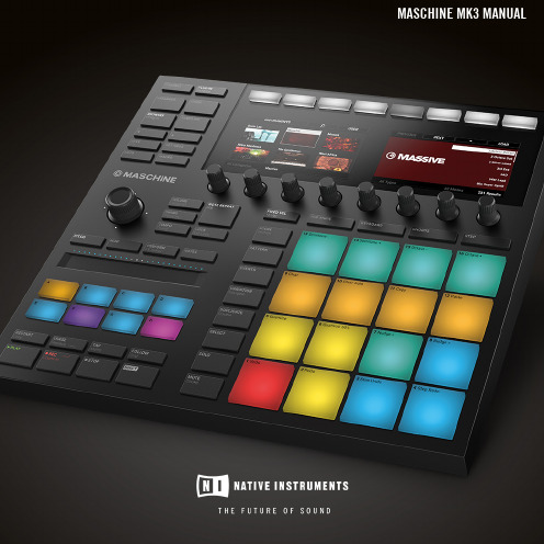
Native Instruments MASCHINE MK3 用户手册说明书
The information in this document is subject to change without notice and does not represent a commitment on the part of Native Instruments GmbH. The software described by this docu-ment is subject to a License Agreement and may not be copied to other media. No part of this publication may be copied, reproduced or otherwise transmitted or recorded, for any purpose, without prior written permission by Native Instruments GmbH, hereinafter referred to as Native Instruments.“Native Instruments”, “NI” and associated logos are (registered) trademarks of Native Instru-ments GmbH.ASIO, VST, HALion and Cubase are registered trademarks of Steinberg Media Technologies GmbH.All other product and company names are trademarks™ or registered® trademarks of their re-spective holders. Use of them does not imply any affiliation with or endorsement by them.Document authored by: David Gover and Nico Sidi.Software version: 2.8 (02/2019)Hardware version: MASCHINE MK3Special thanks to the Beta Test Team, who were invaluable not just in tracking down bugs, but in making this a better product.NATIVE INSTRUMENTS GmbH Schlesische Str. 29-30D-10997 Berlin Germanywww.native-instruments.de NATIVE INSTRUMENTS North America, Inc. 6725 Sunset Boulevard5th FloorLos Angeles, CA 90028USANATIVE INSTRUMENTS K.K.YO Building 3FJingumae 6-7-15, Shibuya-ku, Tokyo 150-0001Japanwww.native-instruments.co.jp NATIVE INSTRUMENTS UK Limited 18 Phipp StreetLondon EC2A 4NUUKNATIVE INSTRUMENTS FRANCE SARL 113 Rue Saint-Maur75011 ParisFrance SHENZHEN NATIVE INSTRUMENTS COMPANY Limited 5F, Shenzhen Zimao Center111 Taizi Road, Nanshan District, Shenzhen, GuangdongChina© NATIVE INSTRUMENTS GmbH, 2019. All rights reserved.Table of Contents1Welcome to MASCHINE (25)1.1MASCHINE Documentation (26)1.2Document Conventions (27)1.3New Features in MASCHINE 2.8 (29)1.4New Features in MASCHINE 2.7.10 (31)1.5New Features in MASCHINE 2.7.8 (31)1.6New Features in MASCHINE 2.7.7 (32)1.7New Features in MASCHINE 2.7.4 (33)1.8New Features in MASCHINE 2.7.3 (36)2Quick Reference (38)2.1Using Your Controller (38)2.1.1Controller Modes and Mode Pinning (38)2.1.2Controlling the Software Views from Your Controller (40)2.2MASCHINE Project Overview (43)2.2.1Sound Content (44)2.2.2Arrangement (45)2.3MASCHINE Hardware Overview (48)2.3.1MASCHINE Hardware Overview (48)2.3.1.1Control Section (50)2.3.1.2Edit Section (53)2.3.1.3Performance Section (54)2.3.1.4Group Section (56)2.3.1.5Transport Section (56)2.3.1.6Pad Section (58)2.3.1.7Rear Panel (63)2.4MASCHINE Software Overview (65)2.4.1Header (66)2.4.2Browser (68)2.4.3Arranger (70)2.4.4Control Area (73)2.4.5Pattern Editor (74)3Basic Concepts (76)3.1Important Names and Concepts (76)3.2Adjusting the MASCHINE User Interface (79)3.2.1Adjusting the Size of the Interface (79)3.2.2Switching between Ideas View and Song View (80)3.2.3Showing/Hiding the Browser (81)3.2.4Showing/Hiding the Control Lane (81)3.3Common Operations (82)3.3.1Using the 4-Directional Push Encoder (82)3.3.2Pinning a Mode on the Controller (83)3.3.3Adjusting Volume, Swing, and Tempo (84)3.3.4Undo/Redo (87)3.3.5List Overlay for Selectors (89)3.3.6Zoom and Scroll Overlays (90)3.3.7Focusing on a Group or a Sound (91)3.3.8Switching Between the Master, Group, and Sound Level (96)3.3.9Navigating Channel Properties, Plug-ins, and Parameter Pages in the Control Area.973.3.9.1Extended Navigate Mode on Your Controller (102)3.3.10Navigating the Software Using the Controller (105)3.3.11Using Two or More Hardware Controllers (106)3.3.12Touch Auto-Write Option (108)3.4Native Kontrol Standard (110)3.5Stand-Alone and Plug-in Mode (111)3.5.1Differences between Stand-Alone and Plug-in Mode (112)3.5.2Switching Instances (113)3.5.3Controlling Various Instances with Different Controllers (114)3.6Host Integration (114)3.6.1Setting up Host Integration (115)3.6.1.1Setting up Ableton Live (macOS) (115)3.6.1.2Setting up Ableton Live (Windows) (116)3.6.1.3Setting up Apple Logic Pro X (116)3.6.2Integration with Ableton Live (117)3.6.3Integration with Apple Logic Pro X (119)3.7Preferences (120)3.7.1Preferences – General Page (121)3.7.2Preferences – Audio Page (126)3.7.3Preferences – MIDI Page (130)3.7.4Preferences – Default Page (133)3.7.5Preferences – Library Page (137)3.7.6Preferences – Plug-ins Page (145)3.7.7Preferences – Hardware Page (150)3.7.8Preferences – Colors Page (154)3.8Integrating MASCHINE into a MIDI Setup (156)3.8.1Connecting External MIDI Equipment (156)3.8.2Sync to External MIDI Clock (157)3.8.3Send MIDI Clock (158)3.9Syncing MASCHINE using Ableton Link (159)3.9.1Connecting to a Network (159)3.9.2Joining and Leaving a Link Session (159)3.10Using a Pedal with the MASCHINE Controller (160)3.11File Management on the MASCHINE Controller (161)4Browser (163)4.1Browser Basics (163)4.1.1The MASCHINE Library (163)4.1.2Browsing the Library vs. Browsing Your Hard Disks (164)4.2Searching and Loading Files from the Library (165)4.2.1Overview of the Library Pane (165)4.2.2Selecting or Loading a Product and Selecting a Bank from the Browser (170)4.2.2.1[MK3] Browsing by Product Category Using the Controller (174)4.2.2.2[MK3] Browsing by Product Vendor Using the Controller (174)4.2.3Selecting a Product Category, a Product, a Bank, and a Sub-Bank (175)4.2.3.1Selecting a Product Category, a Product, a Bank, and a Sub-Bank on theController (179)4.2.4Selecting a File Type (180)4.2.5Choosing Between Factory and User Content (181)4.2.6Selecting Type and Character Tags (182)4.2.7List and Tag Overlays in the Browser (186)4.2.8Performing a Text Search (188)4.2.9Loading a File from the Result List (188)4.3Additional Browsing Tools (193)4.3.1Loading the Selected Files Automatically (193)4.3.2Auditioning Instrument Presets (195)4.3.3Auditioning Samples (196)4.3.4Loading Groups with Patterns (197)4.3.5Loading Groups with Routing (198)4.3.6Displaying File Information (198)4.4Using Favorites in the Browser (199)4.5Editing the Files’ Tags and Properties (203)4.5.1Attribute Editor Basics (203)4.5.2The Bank Page (205)4.5.3The Types and Characters Pages (205)4.5.4The Properties Page (208)4.6Loading and Importing Files from Your File System (209)4.6.1Overview of the FILES Pane (209)4.6.2Using Favorites (211)4.6.3Using the Location Bar (212)4.6.4Navigating to Recent Locations (213)4.6.5Using the Result List (214)4.6.6Importing Files to the MASCHINE Library (217)4.7Locating Missing Samples (219)4.8Using Quick Browse (221)5Managing Sounds, Groups, and Your Project (225)5.1Overview of the Sounds, Groups, and Master (225)5.1.1The Sound, Group, and Master Channels (226)5.1.2Similarities and Differences in Handling Sounds and Groups (227)5.1.3Selecting Multiple Sounds or Groups (228)5.2Managing Sounds (233)5.2.1Loading Sounds (235)5.2.2Pre-listening to Sounds (236)5.2.3Renaming Sound Slots (237)5.2.4Changing the Sound’s Color (237)5.2.5Saving Sounds (239)5.2.6Copying and Pasting Sounds (241)5.2.7Moving Sounds (244)5.2.8Resetting Sound Slots (245)5.3Managing Groups (247)5.3.1Creating Groups (248)5.3.2Loading Groups (249)5.3.3Renaming Groups (251)5.3.4Changing the Group’s Color (251)5.3.5Saving Groups (253)5.3.6Copying and Pasting Groups (255)5.3.7Reordering Groups (258)5.3.8Deleting Groups (259)5.4Exporting MASCHINE Objects and Audio (260)5.4.1Saving a Group with its Samples (261)5.4.2Saving a Project with its Samples (262)5.4.3Exporting Audio (264)5.5Importing Third-Party File Formats (270)5.5.1Loading REX Files into Sound Slots (270)5.5.2Importing MPC Programs to Groups (271)6Playing on the Controller (275)6.1Adjusting the Pads (275)6.1.1The Pad View in the Software (275)6.1.2Choosing a Pad Input Mode (277)6.1.3Adjusting the Base Key (280)6.1.4Using Choke Groups (282)6.1.5Using Link Groups (284)6.2Adjusting the Key, Choke, and Link Parameters for Multiple Sounds (286)6.3Playing Tools (287)6.3.1Mute and Solo (288)6.3.2Choke All Notes (292)6.3.3Groove (293)6.3.4Level, Tempo, Tune, and Groove Shortcuts on Your Controller (295)6.3.5Tap Tempo (299)6.4Performance Features (300)6.4.1Overview of the Perform Features (300)6.4.2Selecting a Scale and Creating Chords (303)6.4.3Scale and Chord Parameters (303)6.4.4Creating Arpeggios and Repeated Notes (316)6.4.5Swing on Note Repeat / Arp Output (321)6.5Using Lock Snapshots (322)6.5.1Creating a Lock Snapshot (322)6.5.2Using Extended Lock (323)6.5.3Updating a Lock Snapshot (323)6.5.4Recalling a Lock Snapshot (324)6.5.5Morphing Between Lock Snapshots (324)6.5.6Deleting a Lock Snapshot (325)6.5.7Triggering Lock Snapshots via MIDI (326)6.6Using the Smart Strip (327)6.6.1Pitch Mode (328)6.6.2Modulation Mode (328)6.6.3Perform Mode (328)6.6.4Notes Mode (329)7Working with Plug-ins (330)7.1Plug-in Overview (330)7.1.1Plug-in Basics (330)7.1.2First Plug-in Slot of Sounds: Choosing the Sound’s Role (334)7.1.3Loading, Removing, and Replacing a Plug-in (335)7.1.3.1Browser Plug-in Slot Selection (341)7.1.4Adjusting the Plug-in Parameters (344)7.1.5Bypassing Plug-in Slots (344)7.1.6Using Side-Chain (346)7.1.7Moving Plug-ins (346)7.1.8Alternative: the Plug-in Strip (348)7.1.9Saving and Recalling Plug-in Presets (348)7.1.9.1Saving Plug-in Presets (349)7.1.9.2Recalling Plug-in Presets (350)7.1.9.3Removing a Default Plug-in Preset (351)7.2The Sampler Plug-in (352)7.2.1Page 1: Voice Settings / Engine (354)7.2.2Page 2: Pitch / Envelope (356)7.2.3Page 3: FX / Filter (359)7.2.4Page 4: Modulation (361)7.2.5Page 5: LFO (363)7.2.6Page 6: Velocity / Modwheel (365)7.3Using Native Instruments and External Plug-ins (367)7.3.1Opening/Closing Plug-in Windows (367)7.3.2Using the VST/AU Plug-in Parameters (370)7.3.3Setting Up Your Own Parameter Pages (371)7.3.4Using VST/AU Plug-in Presets (376)7.3.5Multiple-Output Plug-ins and Multitimbral Plug-ins (378)8Using the Audio Plug-in (380)8.1Loading a Loop into the Audio Plug-in (384)8.2Editing Audio in the Audio Plug-in (385)8.3Using Loop Mode (386)8.4Using Gate Mode (388)9Using the Drumsynths (390)9.1Drumsynths – General Handling (391)9.1.1Engines: Many Different Drums per Drumsynth (391)9.1.2Common Parameter Organization (391)9.1.3Shared Parameters (394)9.1.4Various Velocity Responses (394)9.1.5Pitch Range, Tuning, and MIDI Notes (394)9.2The Kicks (395)9.2.1Kick – Sub (397)9.2.2Kick – Tronic (399)9.2.3Kick – Dusty (402)9.2.4Kick – Grit (403)9.2.5Kick – Rasper (406)9.2.6Kick – Snappy (407)9.2.7Kick – Bold (409)9.2.8Kick – Maple (411)9.2.9Kick – Push (412)9.3The Snares (414)9.3.1Snare – Volt (416)9.3.2Snare – Bit (418)9.3.3Snare – Pow (420)9.3.4Snare – Sharp (421)9.3.5Snare – Airy (423)9.3.6Snare – Vintage (425)9.3.7Snare – Chrome (427)9.3.8Snare – Iron (429)9.3.9Snare – Clap (431)9.3.10Snare – Breaker (433)9.4The Hi-hats (435)9.4.1Hi-hat – Silver (436)9.4.2Hi-hat – Circuit (438)9.4.3Hi-hat – Memory (440)9.4.4Hi-hat – Hybrid (442)9.4.5Creating a Pattern with Closed and Open Hi-hats (444)9.5The Toms (445)9.5.1Tom – Tronic (447)9.5.2Tom – Fractal (449)9.5.3Tom – Floor (453)9.5.4Tom – High (455)9.6The Percussions (456)9.6.1Percussion – Fractal (458)9.6.2Percussion – Kettle (461)9.6.3Percussion – Shaker (463)9.7The Cymbals (467)9.7.1Cymbal – Crash (469)9.7.2Cymbal – Ride (471)10Using the Bass Synth (474)10.1Bass Synth – General Handling (475)10.1.1Parameter Organization (475)10.1.2Bass Synth Parameters (477)11Working with Patterns (479)11.1Pattern Basics (479)11.1.1Pattern Editor Overview (480)11.1.2Navigating the Event Area (486)11.1.3Following the Playback Position in the Pattern (488)11.1.4Jumping to Another Playback Position in the Pattern (489)11.1.5Group View and Keyboard View (491)11.1.6Adjusting the Arrange Grid and the Pattern Length (493)11.1.7Adjusting the Step Grid and the Nudge Grid (497)11.2Recording Patterns in Real Time (501)11.2.1Recording Your Patterns Live (501)11.2.2The Record Prepare Mode (504)11.2.3Using the Metronome (505)11.2.4Recording with Count-in (506)11.2.5Quantizing while Recording (508)11.3Recording Patterns with the Step Sequencer (508)11.3.1Step Mode Basics (508)11.3.2Editing Events in Step Mode (511)11.3.3Recording Modulation in Step Mode (513)11.4Editing Events (514)11.4.1Editing Events with the Mouse: an Overview (514)11.4.2Creating Events/Notes (517)11.4.3Selecting Events/Notes (518)11.4.4Editing Selected Events/Notes (526)11.4.5Deleting Events/Notes (532)11.4.6Cut, Copy, and Paste Events/Notes (535)11.4.7Quantizing Events/Notes (538)11.4.8Quantization While Playing (540)11.4.9Doubling a Pattern (541)11.4.10Adding Variation to Patterns (541)11.5Recording and Editing Modulation (546)11.5.1Which Parameters Are Modulatable? (547)11.5.2Recording Modulation (548)11.5.3Creating and Editing Modulation in the Control Lane (550)11.6Creating MIDI Tracks from Scratch in MASCHINE (555)11.7Managing Patterns (557)11.7.1The Pattern Manager and Pattern Mode (558)11.7.2Selecting Patterns and Pattern Banks (560)11.7.3Creating Patterns (563)11.7.4Deleting Patterns (565)11.7.5Creating and Deleting Pattern Banks (566)11.7.6Naming Patterns (568)11.7.7Changing the Pattern’s Color (570)11.7.8Duplicating, Copying, and Pasting Patterns (571)11.7.9Moving Patterns (574)11.7.10Adjusting Pattern Length in Fine Increments (575)11.8Importing/Exporting Audio and MIDI to/from Patterns (576)11.8.1Exporting Audio from Patterns (576)11.8.2Exporting MIDI from Patterns (577)11.8.3Importing MIDI to Patterns (580)12Audio Routing, Remote Control, and Macro Controls (589)12.1Audio Routing in MASCHINE (590)12.1.1Sending External Audio to Sounds (591)12.1.2Configuring the Main Output of Sounds and Groups (596)12.1.3Setting Up Auxiliary Outputs for Sounds and Groups (601)12.1.4Configuring the Master and Cue Outputs of MASCHINE (605)12.1.5Mono Audio Inputs (610)12.1.5.1Configuring External Inputs for Sounds in Mix View (611)12.2Using MIDI Control and Host Automation (614)12.2.1Triggering Sounds via MIDI Notes (615)12.2.2Triggering Scenes via MIDI (622)12.2.3Controlling Parameters via MIDI and Host Automation (623)12.2.4Selecting VST/AU Plug-in Presets via MIDI Program Change (631)12.2.5Sending MIDI from Sounds (632)12.3Creating Custom Sets of Parameters with the Macro Controls (636)12.3.1Macro Control Overview (637)12.3.2Assigning Macro Controls Using the Software (638)12.3.3Assigning Macro Controls Using the Controller (644)13Controlling Your Mix (646)13.1Mix View Basics (646)13.1.1Switching between Arrange View and Mix View (646)13.1.2Mix View Elements (647)13.2The Mixer (649)13.2.1Displaying Groups vs. Displaying Sounds (650)13.2.2Adjusting the Mixer Layout (652)13.2.3Selecting Channel Strips (653)13.2.4Managing Your Channels in the Mixer (654)13.2.5Adjusting Settings in the Channel Strips (656)13.2.6Using the Cue Bus (660)13.3The Plug-in Chain (662)13.4The Plug-in Strip (663)13.4.1The Plug-in Header (665)13.4.2Panels for Drumsynths and Internal Effects (667)13.4.3Panel for the Sampler (668)13.4.4Custom Panels for Native Instruments Plug-ins (671)13.4.5Undocking a Plug-in Panel (Native Instruments and External Plug-ins Only) (675)13.5Controlling Your Mix from the Controller (677)13.5.1Navigating Your Channels in Mix Mode (678)13.5.2Adjusting the Level and Pan in Mix Mode (679)13.5.3Mute and Solo in Mix Mode (680)13.5.4Plug-in Icons in Mix Mode (680)14Using Effects (681)14.1Applying Effects to a Sound, a Group or the Master (681)14.1.1Adding an Effect (681)14.1.2Other Operations on Effects (690)14.1.3Using the Side-Chain Input (692)14.2Applying Effects to External Audio (695)14.2.1Step 1: Configure MASCHINE Audio Inputs (695)14.2.2Step 2: Set up a Sound to Receive the External Input (698)14.2.3Step 3: Load an Effect to Process an Input (700)14.3Creating a Send Effect (701)14.3.1Step 1: Set Up a Sound or Group as Send Effect (702)14.3.2Step 2: Route Audio to the Send Effect (706)14.3.3 A Few Notes on Send Effects (708)14.4Creating Multi-Effects (709)15Effect Reference (712)15.1Dynamics (713)15.1.1Compressor (713)15.1.2Gate (717)15.1.3Transient Master (721)15.1.4Limiter (723)15.1.5Maximizer (727)15.2Filtering Effects (730)15.2.1EQ (730)15.2.2Filter (733)15.2.3Cabinet (737)15.3Modulation Effects (738)15.3.1Chorus (738)15.3.2Flanger (740)15.3.3FM (742)15.3.4Freq Shifter (743)15.3.5Phaser (745)15.4Spatial and Reverb Effects (747)15.4.1Ice (747)15.4.2Metaverb (749)15.4.3Reflex (750)15.4.4Reverb (Legacy) (752)15.4.5Reverb (754)15.4.5.1Reverb Room (754)15.4.5.2Reverb Hall (757)15.4.5.3Plate Reverb (760)15.5Delays (762)15.5.1Beat Delay (762)15.5.2Grain Delay (765)15.5.3Grain Stretch (767)15.5.4Resochord (769)15.6Distortion Effects (771)15.6.1Distortion (771)15.6.2Lofi (774)15.6.3Saturator (775)15.7Perform FX (779)15.7.1Filter (780)15.7.2Flanger (782)15.7.3Burst Echo (785)15.7.4Reso Echo (787)15.7.5Ring (790)15.7.6Stutter (792)15.7.7Tremolo (795)15.7.8Scratcher (798)16Working with the Arranger (801)16.1Arranger Basics (801)16.1.1Navigating Song View (804)16.1.2Following the Playback Position in Your Project (806)16.1.3Performing with Scenes and Sections using the Pads (807)16.2Using Ideas View (811)16.2.1Scene Overview (811)16.2.2Creating Scenes (813)16.2.3Assigning and Removing Patterns (813)16.2.4Selecting Scenes (817)16.2.5Deleting Scenes (818)16.2.6Creating and Deleting Scene Banks (820)16.2.7Clearing Scenes (820)16.2.8Duplicating Scenes (821)16.2.9Reordering Scenes (822)16.2.10Making Scenes Unique (824)16.2.11Appending Scenes to Arrangement (825)16.2.12Naming Scenes (826)16.2.13Changing the Color of a Scene (827)16.3Using Song View (828)16.3.1Section Management Overview (828)16.3.2Creating Sections (833)16.3.3Assigning a Scene to a Section (834)16.3.4Selecting Sections and Section Banks (835)16.3.5Reorganizing Sections (839)16.3.6Adjusting the Length of a Section (840)16.3.6.1Adjusting the Length of a Section Using the Software (841)16.3.6.2Adjusting the Length of a Section Using the Controller (843)16.3.7Clearing a Pattern in Song View (843)16.3.8Duplicating Sections (844)16.3.8.1Making Sections Unique (845)16.3.9Removing Sections (846)16.3.10Renaming Scenes (848)16.3.11Clearing Sections (849)16.3.12Creating and Deleting Section Banks (850)16.3.13Working with Patterns in Song view (850)16.3.13.1Creating a Pattern in Song View (850)16.3.13.2Selecting a Pattern in Song View (850)16.3.13.3Clearing a Pattern in Song View (851)16.3.13.4Renaming a Pattern in Song View (851)16.3.13.5Coloring a Pattern in Song View (851)16.3.13.6Removing a Pattern in Song View (852)16.3.13.7Duplicating a Pattern in Song View (852)16.3.14Enabling Auto Length (852)16.3.15Looping (853)16.3.15.1Setting the Loop Range in the Software (854)16.4Playing with Sections (855)16.4.1Jumping to another Playback Position in Your Project (855)16.5Triggering Sections or Scenes via MIDI (856)16.6The Arrange Grid (858)16.7Quick Grid (860)17Sampling and Sample Mapping (862)17.1Opening the Sample Editor (862)17.2Recording Audio (863)17.2.1Opening the Record Page (863)17.2.2Selecting the Source and the Recording Mode (865)17.2.3Arming, Starting, and Stopping the Recording (868)17.2.5Using the Footswitch for Recording Audio (871)17.2.6Checking Your Recordings (872)17.2.7Location and Name of Your Recorded Samples (876)17.3Editing a Sample (876)17.3.1Using the Edit Page (877)17.3.2Audio Editing Functions (882)17.4Slicing a Sample (890)17.4.1Opening the Slice Page (891)17.4.2Adjusting the Slicing Settings (893)17.4.3Live Slicing (898)17.4.3.1Live Slicing Using the Controller (898)17.4.3.2Delete All Slices (899)17.4.4Manually Adjusting Your Slices (899)17.4.5Applying the Slicing (906)17.5Mapping Samples to Zones (912)17.5.1Opening the Zone Page (912)17.5.2Zone Page Overview (913)17.5.3Selecting and Managing Zones in the Zone List (915)17.5.4Selecting and Editing Zones in the Map View (920)17.5.5Editing Zones in the Sample View (924)17.5.6Adjusting the Zone Settings (927)17.5.7Adding Samples to the Sample Map (934)18Appendix: Tips for Playing Live (937)18.1Preparations (937)18.1.1Focus on the Hardware (937)18.1.2Customize the Pads of the Hardware (937)18.1.3Check Your CPU Power Before Playing (937)18.1.4Name and Color Your Groups, Patterns, Sounds and Scenes (938)18.1.5Consider Using a Limiter on Your Master (938)18.1.6Hook Up Your Other Gear and Sync It with MIDI Clock (938)18.1.7Improvise (938)18.2Basic Techniques (938)18.2.1Use Mute and Solo (938)18.2.2Use Scene Mode and Tweak the Loop Range (939)18.2.3Create Variations of Your Drum Patterns in the Step Sequencer (939)18.2.4Use Note Repeat (939)18.2.5Set Up Your Own Multi-effect Groups and Automate Them (939)18.3Special Tricks (940)18.3.1Changing Pattern Length for Variation (940)18.3.2Using Loops to Cycle Through Samples (940)18.3.3Using Loops to Cycle Through Samples (940)18.3.4Load Long Audio Files and Play with the Start Point (940)19Troubleshooting (941)19.1Knowledge Base (941)19.2Technical Support (941)19.3Registration Support (942)19.4User Forum (942)20Glossary (943)Index (951)1Welcome to MASCHINEThank you for buying MASCHINE!MASCHINE is a groove production studio that implements the familiar working style of classi-cal groove boxes along with the advantages of a computer based system. MASCHINE is ideal for making music live, as well as in the studio. It’s the hands-on aspect of a dedicated instru-ment, the MASCHINE hardware controller, united with the advanced editing features of the MASCHINE software.Creating beats is often not very intuitive with a computer, but using the MASCHINE hardware controller to do it makes it easy and fun. You can tap in freely with the pads or use Note Re-peat to jam along. Alternatively, build your beats using the step sequencer just as in classic drum machines.Patterns can be intuitively combined and rearranged on the fly to form larger ideas. You can try out several different versions of a song without ever having to stop the music.Since you can integrate it into any sequencer that supports VST, AU, or AAX plug-ins, you can reap the benefits in almost any software setup, or use it as a stand-alone application. You can sample your own material, slice loops and rearrange them easily.However, MASCHINE is a lot more than an ordinary groovebox or sampler: it comes with an inspiring 7-gigabyte library, and a sophisticated, yet easy to use tag-based Browser to give you instant access to the sounds you are looking for.What’s more, MASCHINE provides lots of options for manipulating your sounds via internal ef-fects and other sound-shaping possibilities. You can also control external MIDI hardware and 3rd-party software with the MASCHINE hardware controller, while customizing the functions of the pads, knobs and buttons according to your needs utilizing the included Controller Editor application. We hope you enjoy this fantastic instrument as much as we do. Now let’s get go-ing!—The MASCHINE team at Native Instruments.MASCHINE Documentation1.1MASCHINE DocumentationNative Instruments provide many information sources regarding MASCHINE. The main docu-ments should be read in the following sequence:1.MASCHINE Getting Started: This document provides a practical approach to MASCHINE viaa set of tutorials covering easy and more advanced tasks in order to help you familiarizeyourself with MASCHINE.2.MASCHINE Manual (this document): The MASCHINE Manual provides you with a compre-hensive description of all MASCHINE software and hardware features.Additional documentation sources provide you with details on more specific topics:▪Controller Editor Manual: Besides using your MASCHINE hardware controller together withits dedicated MASCHINE software, you can also use it as a powerful and highly versatileMIDI controller to pilot any other MIDI-capable application or device. This is made possibleby the Controller Editor software, an application that allows you to precisely define all MIDIassignments for your MASCHINE controller. The Controller Editor was installed during theMASCHINE installation procedure. For more information on this, please refer to the Con-troller Editor Manual available as a PDF file via the Help menu of Controller Editor.▪Online Support Videos: You can find a number of support videos on The Official Native In-struments Support Channel under the following URL: https:///NIsupport-EN. We recommend that you follow along with these instructions while the respective ap-plication is running on your computer.Other Online Resources:If you are experiencing problems related to your Native Instruments product that the supplied documentation does not cover, there are several ways of getting help:▪Knowledge Base▪User Forum▪Technical Support▪Registration SupportYou will find more information on these subjects in the chapter Troubleshooting.1.2Document ConventionsThis section introduces you to the signage and text highlighting used in this manual. This man-ual uses particular formatting to point out special facts and to warn you of potential issues. The icons introducing these notes let you see what kind of information is to be expected:This document uses particular formatting to point out special facts and to warn you of poten-tial issues. The icons introducing the following notes let you see what kind of information can be expected:Furthermore, the following formatting is used:▪Text appearing in (drop-down) menus (such as Open…, Save as… etc.) in the software and paths to locations on your hard disk or other storage devices is printed in italics.▪Text appearing elsewhere (labels of buttons, controls, text next to checkboxes etc.) in the software is printed in blue. Whenever you see this formatting applied, you will find the same text appearing somewhere on the screen.▪Text appearing on the displays of the controller is printed in light grey. Whenever you see this formatting applied, you will find the same text on a controller display.▪Text appearing on labels of the hardware controller is printed in orange. Whenever you see this formatting applied, you will find the same text on the controller.▪Important names and concepts are printed in bold.▪References to keys on your computer’s keyboard you’ll find put in square brackets (e.g.,“Press [Shift] + [Enter]”).►Single instructions are introduced by this play button type arrow.→Results of actions are introduced by this smaller arrow.Naming ConventionThroughout the documentation we will refer to MASCHINE controller (or just controller) as the hardware controller and MASCHINE software as the software installed on your computer.The term “effect” will sometimes be abbreviated as “FX” when referring to elements in the MA-SCHINE software and hardware. These terms have the same meaning.Button Combinations and Shortcuts on Your ControllerMost instructions will use the “+” sign to indicate buttons (or buttons and pads) that must be pressed simultaneously, starting with the button indicated first. E.g., an instruction such as:“Press SHIFT + PLAY”means:1.Press and hold SHIFT.2.While holding SHIFT, press PLAY and release it.3.Release SHIFT.Unlabeled Buttons on the ControllerThe buttons and knobs above and below the displays on your MASCHINE controller do not have labels.。
flink 1.11 unaligned checkpint 原理 -回复
flink 1.11 unaligned checkpint 原理-回复Flink 1.11中引入了一项新功能,即非对齐检查点(unaligned checkpoint),它可以显著改善检查点的持久化性能。
在本文中,我们将逐步介绍非对齐检查点的原理,并解释其如何提高Flink应用程序的效率。
一、什么是检查点?在分布式流处理系统中,检查点是一种容错机制,用于将应用程序的状态保存到外部存储器中,以便在故障发生时能够恢复到先前的状态。
检查点通常由协调器节点触发,并由任务管理器负责将应用程序的状态写入持久化存储。
二、传统检查点的问题在传统的Flink版本中,检查点是通过同步机制实现的,任务管理器会在执行检查点时停止计算,并将应用程序的状态写入持久化存储。
这种同步方式对于一些大规模应用程序来说效率较低,因为它会阻塞应用程序的执行。
三、非对齐检查点的原理非对齐检查点是Flink 1.11中的一项创新功能,它采用了异步机制,不会阻塞应用程序的执行。
非对齐检查点的原理如下:1. 异步快照非对齐检查点采用了异步快照的方式,即任务管理器不需要等待所有任务完成当前状态的快照,而是在接收到快照请求后立即触发快照,并将快照写入持久化存储。
这样,快照的写入和应用程序的计算可以并发进行,提高了系统的整体吞吐量。
2. 异步对齐在非对齐检查点中,任务管理器在实时计算的同时,会持续地生成和写入快照。
这些快照会被分为不同的存储块(blocks),每个存储块包含一段时间内的状态更新。
与此同时,协调器节点会定期地读取存储块并保留最新的状态。
3. 增量检查点与传统的全量检查点相比,非对齐检查点采用了增量检查点的方式。
当一个任务被触发快照时,它只会将自己的状态更新写入快照存储,而不是整个状态。
这样可以减少快照的大小,提高了存储的效率。
4. 异步恢复在故障发生后,非对齐检查点可以更快地进行恢复。
协调器节点会首先恢复最新的状态,并将其发送给任务管理器。
ANSI-ESD ADV1.0-2009
ESD ADV1.0-2009Revision of ESD ADV1.0-2004for Electrostatic DischargeTerminologyGlossaryElectrostatic Discharge Association7900 Turin Road, Bldg. 3Rome, NY 13440ESD ADV1.0-2009for Electrostatic DischargeTerminologyGlossary Updated July 28, 2010ESD AssociationESD ADV1.0-2009iElectrostatic Discharge Association (ESDA) standards and publications are designed to serve the public interest by eliminating misunderstandings between manufacturers and purchasers, facilitating the interchangeability and improvement of products and assisting the purchaser in selecting and obtaining the proper product for his particular needs. The existence of such standards and publications shall not in any respect preclude any member or non-member of the Association from manufacturing or selling products not conforming to such standards and publications. Nor shall the fact that a standard or publication is published by the Association preclude its voluntary use by non-members of the Association whether the document is to be used either domestically or internationally. Recommended standards and publications are adopted by the ESDA in accordance with the ANSI Patent policy.Interpretation of ESDA Standards: The interpretation of standards in-so-far as it may relate to a specific product or manufacturer is a proper matter for the individual company concerned and cannot be undertaken by any person acting for the ESDA. The ESDA Standards Chairman may make comments limited to an explanation or clarification of the technical language or provisions in a standard, but not related to its application to specific products and manufacterers. No other person is authorized to comment on behalf of the ESDA on any ESDA Standard.THE CONTENTS OF ESDA’S STANDARDS AND PUBLICATIONS ARE PROVIDED “AS-IS,” AND ESDA MAKES NO REPRESENTATIONS OR WARRANTIES, EXPRESS OR IMPLIED, OF ANY KIND WITH RESPECT TO SUCH CONTENTS. ESDA DISCLAIMS ALL REPRESENTATIONS AND WARRANTIES, INCLUDING WITHOUT LIMITATION, WARRANTIES OF MERCHANTABILITY, FITNESS FOR PARTICULAR PURPOSE OR USE, TITLE AND NON-INFRINGEMENT.ESDA STANDARDS AND PUBLICATIONS ARE CONSIDERED TECHNICALLY SOUND AT THE TIME THEY ARE APPROVED FOR PUBLICATION. THEY ARE NOT A SUBSTITUTE FOR A PRODUCT SELLER’S OR USER’S OWN JUDGEMENT WITH RESPECT TO ANY PARTICULAR PRODUCT DISCUSSED, AND ESDA DOES NOT UNDERTAKE TO GUARANTY THE PERFORMANCE OF ANY INDIVIDUAL MANUFACTURERS’ PRODUCTS BY VIRTUE OF SUCH STANDARDS OR PUBLICATIONS. THUS, ESDA EXPRESSLY DISLAIMS ANY RESPONSIBILITY FOR DAMAGES ARISING FROM THE USE, APPLICATION, OR RELIANCE BY OTHERS ON THE INFORMATION CONTAINED IN THESE STANDARDS OR PUBLICATIONS.NEITHER ESDA, NOR ITS MEMBERS, OFFICERS, EMPLOYEES OR OTHER REPRESENTATIVES WILL BE LIABLE FOR DAMAGES ARISING OUT OF OR IN CONNECTION WITH THE USE OR MISUSE OF ESDA STANDARDS OR PUBLICATIONS, EVEN IF ADVISED OF THE POSSIBILITY THEROF. THIS IS A COMPREHENSIVE LIMITATION OF LIABILITY THAT APPLIES TO ALL DAMAGES OF ANY KIND, INCLUDING WITHOUT LIMITATION, LOSS OF DATA, INCOME OR PROFIT, LOSS OF OR DAMAGE TO PROPERTY AND CLAIMS OF THIRD PARTIES.Published by:Electrostatic Discharge Association 7900 Turin Road, Bldg. 3 Rome, NY 13440Copyright © 2009 by ESD Association All rights reservedNo part of this publication may be reproduced in any form, in an electronic retrieval system or otherwise, without the prior written permission of the publisher.Printed in the United States of AmericaDISCLAIMER OF WARRANTIESDISCLAIMER OF GUARANTYLIMITATION ON ESDA’s LIABILITYCAUTION NOTICEESD Association Advisory ESD ADV1.0-2009 ESD Association Advisory for Electrostatic Discharge Terminology – Glossary1.0 PURPOSEThe purpose of this Glossary is to promote technically correct terminology in the electrical overstress/electrostatic discharge (EOS/ESD) community.2.0 SCOPEThis document contains unified definitions and explanations of terminology used in the standards, TR20.20 Handbook, and other documents of the ESD Association. The Glossary compares EOS/ESD industry terminology with the more familiar usages of electrical and electronic terms. Although the Glossary is not intended to be an encyclopedia, it includes historical information (including explanations of obsolete terminology) and clarifies terminology in other EOS/ESD-related documents.The Glossary is revised as needed so that it evolves continually along with the evolving knowledge of EOS/ESD phenomena and protective methods.New revisions of the Glossary cover all issued standards, standard practices, standard test methods in effect at the time the revision, but not necessarily draft documents. At the time of each edition’s publication, the Glossary includes the most recent updates of the definitions from all issued ESD Association standards.3.0 DEFINITIONSAC equipment grounda) The ground point at which the equipment grounding conductor is bonded to any piece ofequipment, at the equipment end of the conductor in a single-phase 120VAC electricalservice.b) The 3rd wire (green/green with yellow stripe) terminal of a receptacle.NOTE: Wiring colors may vary by National Electrical Code.c) The entire low impedance path (electrically equivalent to the equipment grounding conductor)from a piece of electrical equipment to the neutral bus at the main service equipment). acceptance equipmentAn instrument or collection of instruments that meet the criteria of a standard or standard test method and provides a measurement that is repeatable. It may or may not be as accurate as laboratory evaluation equipment. This equipment is typically used to verify materials, devices or procedures under in-use conditions.acceptance testingIncoming tests to confirm proper marking and electrical functionality. Data are the form of visual inspection records, and values or pass/fail notation.active componentsSemiconductor devices and elements such as transistors and diodes, amplifiers, and rectifiers that can change their basic characteristics in a powered electrical circuit.air conductivityThe ability of air to conduct (pass) an electric current under the influence of an electric field.air ionsMolecular clusters of about 10 molecules (water, impurities, etc.) bound by polarization forces to a singly charged oxygen or nitrogen molecule.1ESD ADV1.0-2009air ionizerA source of charged air molecules (ions).amplitudeThe value chosen to be specific to the waveform, typically the difference between the baseline and the first peak.ankle strapSee ground strap.antistat, agentA substance that is part of or topically applied to a material to render the material surface static dissipative or less susceptible to triboelectric charging.antistatic Usually refers to the property of a material that inhibits triboelectric charging. Note: A material's antistatic characteristic is not necessarily co-relatable with its resistively or resistance.attenuatorA resistive network with coaxial connectors to reduce the amplitude of a signal by a specified amount.automated handling equipment (AHE)Any form of self-sequencing machinery that manipulates or transports product in any form; e.g. wafers, packaged devices, paper, textiles, etc.auxiliary groundA separate supplemental grounding conductor for use other than general equipment grounding. bandwidthThe high frequency limit where the amplitude of a component of system has decreased to 0.707 (-3 dB) of the constant amplitude low frequency response.barrier stripA device or apparatus that consists of a metal strip and connectors or screws that allow termination and connection of wires or conductors from various components of an electrostatic discharge protected workstation.bipolar ionizerA device that generates both positively and negatively charged ions.body contacting mechanism (BCM)The part of the foot grounder that makes electrical contact with the body.bond or bondingThe permanent joining of metallic parts to form an electrically conductive path that will assure electrical continuity and the capacity to safely conduct any current likely to be imposed.bonding conductorThe wire, strap, flange or other electrically conductive mechanical device used to interconnect two otherwise isolated conductive or dissipative items.breakaway forceThe force required to disconnect the ground cord from the cuff.2ESD ADV1.0-2009 bus barA metal strip or bar to which several conductors may be bonded.bypass capacitorA capacitor placed between power and ground to provide a more stable power supply voltage by shunting high frequency signals (such as device switching noise) and/or to provide local power storage (to reduce supply voltage variations when device current usage changes).cable discharge currentA current produced by causing a stored charge to flow in or out of a cable conductor.cable discharge eventOccurrence of an Electrostatic Discharge Event (CDE) when the cable is connected to an electrical system or equipment. Examples of sources include Ethernet cables, T1 lines and other communications or data lines.charge decayThe decrease and/or neutralization of a net electrostatic charge.charge inductionThe displacement of charge in an isolated conductor when placed in an electric field (for example, from a charged body). Note: Momentary grounding of such a conductor would result in its gaining a net charge.charged device model (CDM) electrostatic discharge (ESD)An ESD stress model that approximates the discharge event that occurs when a charged component is quickly discharged to another object at a lower electrostatic potential through a signal pin or terminal.charged device model (CDM) electrostatic discharge (ESD) testerEquipment that simulates the component level CDM ESD event using the non-socketed test method.charged plate monitor (CPM)An instrument used to measure the charge neutralization properties of ionization equipment. coaxial resistive probeA resistor (for example, a 1.0 ohm disk resistor) used to measure the CDM discharge current. coaxial transmission lineA coaxial cable with controlled impedance used for transferring a signal with minimum loss from one point of the system to another.cold healingThe spontaneous recovery, at room temperature, of an item from a parametric change caused by electrostatic discharge.cold workstationA work area that has items, assemblies, black boxes, or systems which no power is applied. common connection pointA device or location (less than 1 ohm within itself) where the conductors of two or more ESD technical elements are connected in order to bring the ungrounded ESD technical elements to the same electrical potential through equipotential bonding.3ESD ADV1.0-2009common point groundA grounded device or location where the conductors of one or more technical elements are bonded.compliance (periodic) verificationTesting done to indicate that the performance has not changed from initial baseline values to exceed selected limits.compliance verification (periodic testing) equipmentAn instrument or collection of instruments that provide an indication or measurement. It may or may not be repeatable or accurate. This equipment is typically used for indications of pass or fail. componentAn active or passive item such as a resistor, diode, transistor, integrated circuit or hybrid circuit. component failureA condition in which a tested component does not meet one or more specified static or dynamic data sheet parameters.component under test (CUT)A passive or active element, device, integrated circuit, module or subsystem being tested. The CUT is intended to become part of a completed system but is not the entire system.compressed gas ionizerIonization devices that can be used to neutralize charged surfaces and / or remove surface particles with pressurized gas. This type of ionizer may be used to ionize the gas within production equipment.conductive flooring materialA floor material that has a resistance to ground of less than 1.0 x 10⁶ ohms.conductive material, resistanceA material that has a surface resistance of less than 1 x 10⁴ ohms or a volume resistance of less than 1 x 10⁴ ohms.conductive material, resistivityA material that has a surface resistivity less than 1 x 10⁵ ohms/square or a volume resistivity less than 1 x 10⁴ ohm-cm.conductivitya. The ratio of the current per unit area (current density) to the electric field in a material.Conductivity is expressed in units of siemens/meter.b. In non-technical usage, the ability to conduct current.constant area and force electrode (CAFÉ)An electrode designed to be held by a person’s finger, gloved or ungloved, to reproducibly measure resistance from the finger to a counter electrode such as a ground strap worn on the wrist of the same hand. This electrode is suitable for measuring the resistance of a finger wearing a finger cot.contact-mode dischargeAn ESD event initiated within a relay. The relay is connected to the component pin via a probe, and the component is not in a socket.contact-mode, non-socketed dischargeSee constant-mode discharge.4ESD ADV1.0-2009 coronaThe production of positive and negative ions by a very localized high electric field. The field is normally established by applying a high voltage to a conductor in the shape of a sharp point or wire.correlation sampleA representative device used for correlating measured voltages with known applied voltages. critical path componentsAny portion of the AHE within a certain distance of the device path. That distance should be agreed upon between the manufacturer and end user.cuffThe portion of the wrist strap worn on the wrist. The cuff maintains electrical contact with a person’s skin.current limiting resistanceA resistance value incorporated in series with the wrist strap or foot grounder’s electrical path to ground. This resistance limits electrical current that could pass through the grounding mechanism in the event of inadvertent user contact with electrical potential.current sense resistorA resistor, R CS, of less than five ohms which produces a measurable voltage proportional to current through it with an intrinsic rise-time response three times faster than the fastest rise-time to be measured. ∆v=∆i x R CS.current sensorA device used to measure the current in a circuit or system. This device could be non-invasive (by sensing the change in magnetic flux lines) or be very low impedance inserted in series (such as the ESD target).current source methodA TLP methodology (sometimes referred to as constant current method) that utilizes a 500 ohm resistor in series with the DUT and measures the voltage and current at the DUT.data sheet parametersStatic and dynamic component performance data supplied by the component manufacturer or user.DC resistanceThe ratio of the DC voltage applied to a conductor to the CD current through it.decay rateThe decrease of charge or voltage per unit time.decay timeThe time required for an electrostatic potential to be reduced to a given percentage (usually 10%) of its initial value. (See Static Decay Test.)delay lineA transmission line used to introduce signal delay between two components of a system. destructive damageDamage where the operating electrical characteristics or parameters are altered and do not recover to the initial conditions prior to stress.5ESD ADV1.0-2009deviceProduct being processed by AHE (e.g., an integrated circuit [IC] or a printed circuit [PC] board). device pathThe route traveled by a device in an AHE.device under test (DUT)The device to which the Transient Stimulus will be applied.di/dtCurrent derivative: the slope of the tangent at a particular point in time of the current signal. dielectricAn insulating material that can sustain an electric field with little current flow.dielectric breakdown voltageThe electric potential across an insulating material that causes a sudden increase in current through the material of the insulator.dielectric strengthThe maximum electric field that a dielectric can sustain.discharge currentA current produced by causing a stored charge to flow out of a component into a conductor from an ESD simulator.discharge timeThe time necessary for a voltage (due to an electrostatic charge) to decay from an initial value to some arbitrarily chosen final value.discrete componentAn elementary electronic device constructed as a single unit such as a transistor, resistor, capacitor, inductor, diode, etc.dissipative floor materialFloor material that has a resistance to ground between 1.0 x 10⁶ and 1.0 x 10⁹ ohms.dissipative MaterialsA material that has a surface resistance greater than or equal to 1 x 10E4 ohms but less than 1 x 10E11 ohms or a volume resistance greater than or equal to 1 x 10E4 ohms but less than 1 x10E11 ohms.dynamic parametersDynamic parameters are those measured with the component in a functioning (operating) condition. These parameters may include, but are not limited to: full functionality, output rise and fall times under a specified load condition, and dynamic current draw.dynamic stateAny operational state where the device is functioning according to its design. Typically, inputs, I/O, and output pins are changing as a required to operate the device. In the dynamic state, the supply current should be changing throughout the range of I DDNOM.earth grounding electrodeThe metal rod, metal plate, metal pipe, metal mesh, metal underground water pipe, or grounded metal building frame that are bonded to the neutral bus at the main service entrance.6electric chargeAn absence or excess of electrons.electric field shielding materialsA material that has a surface resistance or a volume resistance of less than 1 x 10³.electrical ionizerA device that creates ions in gases by use of high voltage electrodes.electrical overstress (EOS)The exposure of an item to a current or voltage beyond its maximum ratings. This exposure may or may not result in a catastrophic failure.electrification periodThe average of five (5) electrification times, plus five (5) seconds.electrification timeThe time for the resistance measuring instrument to stabilize at the value of the upper resistance range verification fixture.electrostatic chargeElectric charge at rest.electrostatic damageChange to an item caused by an electrostatic discharge that makes it fail to meet one or more specified parameters.electrostatic discharge (ESD)The rapid, spontaneous transfer of electrostatic charge induced by a high electrostatic field. Note: Usually, the charge flows through a spark between two bodies at different electrostatic potentials as they approach one another. Details of such processes, such as the rate of the charge transfer, are described in specific electrostatic discharge models.electrostatic discharge (ESD) controlSee static control.electrostatic discharge (ESD) groundThe point, electrodes, bus bar, metal strips, or other system of conductors that form a path from a statically charged person or object to ground.electrostatic discharge (ESD) protectiveA property of materials capable of one or more of the following: reducing the generation of static electricity, dissipating electrostatic charges over its surface or volume, or providing shielding from ESD or electrostatic fields.electrostatic discharge (ESD) protective symbolThe graphics used to identify items that are specifically designed to provide electrostatic discharge protection.electrostatic discharge (ESD) protective workstationAn area that is constructed and equipped with the necessary protective materials and equipment to limit damage to electrostatic discharge susceptible items handled therein.electrostatic discharge (ESD) protective worksurfaceA worksurface that dissipates electrostatic charge from materials placed on the surface or from the surface itself.7electrostatic discharge sensitivity (ESDS)The ESD level that causes component failure. (Note: See also electrostatic discharge susceptibility.)electrostatic discharge (ESD) shieldA barrier or enclosure that limits the passage of current and attenuates an electromagnetic field resulting from an electrostatic discharge.electrostatic discharge (ESD) spark testingTesting performed with operating equipment or parts to determine their susceptibility to the transient electromagnetic fields produced by an air discharge event.electrostatic discharge susceptibility (ESDS)The propensity to be damaged by electrostatic discharge. (See also electrostatic discharge sensitivity).electrostatic discharge susceptibility (ESDS) classificationThe classification of items according to electrostatic discharge susceptibility voltage ranges. Note: There are various classification methods.electrostatic discharge susceptibility (ESDS) symbolThe graphics placed on hardware, assemblies, and documentation for identification of electrostatic discharge susceptible items.electrostatic discharge susceptible (ESDS) itemElectrical or electronic piece part, device, component, assembly, or equipment item that has some level of electrostatic discharge susceptibility.electrostatic discharge (ESD) withstand voltageThe maximum electrostatic discharge (ESD) level that does not cause component failure. electrostatic fieldAn attractive or repulsive force in space due to the presence of electric charge.electrostatic potentialThe voltage difference between a point and an agreed upon reference.electrostatic shieldA barrier or enclosure that limits the penetration of an electrostatic field.electrostaticsThe study of electrostatic charge and its effects.emitterA conducting sharp object, usually a needle or wire, which will cause a corona discharge when kept at a high potential.energizedThe state of a piece of equipment such that it carries electrical, fluid, thermal, mechanical or other form of energy in a state which could pose a hazard to personnel.EOSSee electrical overstress.equipment grounding conductorThe conductor used to connect the non-current carrying metal parts of equipment, raceways and other enclosures to the main service equipment ground bus.equipotentialHaving the same electrical potential; of uniform electrical potential throughout.ESDSee electrostatic discharge.ESD eventOccurrence of a single electrostatic discharge from any source. Examples of source include humans, ESD simulators and other charged objects.ESD grounding / bonding reference pointThe ESD grounding system selected for use in a facility or situation that best suits the application: a) AC equipment ground; b) auxiliary ground; c) equipotential bondingESD protected area (EPA)A defined location with the necessary materials, tools and equipment capable of controlling static electricity to a level that minimizes damage to ESD susceptible items.ESD targetA current transducer used to measure ESD discharges.ESD target adapterAn adapter used to connect reference generators to the ESD target.ESD technical elementsAll of the items, materials, devices, tools and equipment used within an EPA for the control of static electricity.ESDSSee Electrostatic Discharge Susceptibleevaluation testingStringent testing of a wrist strap to determine its electrical and mechanical performance abilities. Data are in the form of values from laboratory testing.failure threshold currentThe supply current value that when exceeded, is considered to have failed the device. To avoid false failures due to changes of state it should be greater than the nominal supply current (I DDNOM).faraday cageA conductive enclosure that attenuates a stationary electrostatic field.field induced chargingA charging method using electrostatic induction.field plate (FP)A conductive plate used to elevate the potential of the device under test (DUT) by capacitive coupling.9final test voltageThe voltage on the test plate of the periodic verification instrument at which the discharge time test ends.floor contacting surface (FCS)That part of the foot grounder that makes electrical contact to the grounding surface.flooring / foot grounder system resistanceThe total resistance of the foot grounders when worn by the person standing on a static floor or stainless steel plate.foot grounderPersonnel grounding device worn on the shoe. The device makes electrical contact with the surface on which the wearer is standing. The device also makes contact with the wearer through either direct skin contact or by contacting moisture inside the shoe. This definition includes heel / toe grounders and booties or similar devices (excluding static control shoes).foot grounder systemA foot grounder properly worn by a person where the electrical path includes the person and the foot grounder.functional stateThe functional state of the device defines the mode in which it is operating.functional testingEnd-use testing to confirm electrical functionality. Data is in the form of pass/fail notation or values.FWHMFull Width at Half Maximumgarment systemAny electrically interconnected components of static control apparel.grounda. A conducting connection, whether intentional or accidental between an electrical circuit orequipment and the earth, or to some conducting body that serves in place of earth.b. The position or portion of an electrical current at zero potential with respect to the earth.c. A conducting body, such as the earth of the hull of a steel ship used as a return path forelectric currents and as an arbitrary zero reference point.ground cordThe portion of the wrist strap that provides flexibility of movement while completing the electrical circuit between the cuff and ground.ground currentThe current flowing out of the ground pin.ground fault circuit interrupterA device intended for the protection of personnel that functions to de-energize a circuit or portion thereof within an established period of time. It is activated when a current difference between the neutral and hot conductors exceeds some predetermined value that is less than that required to operate the overcurrent protective device of the supply circuit. The current difference is usually caused by a current to ground.ground leadThe portion of the wrist strap, which provides flexibility of movement while completing the electrical circuit between the cuff at one end and a ground system at the other.ground pinThe pin or set of pins that return current to the supply voltage source.ground plane (GP)A conductive plate used to complete the circuitry for grounding / discharging the DUT.ground reference pointThe prong of the equipment’s ground wire from hand soldering equipment to a workstation ground point. Examples are: (a) The ground U-prong (or round prong) of an AC power cord; (b) the banana plug of a grounding patch cord; (c) the ring or spade lug of a ground jumper wire. ground strapa. A conductor intended to provide an electrical path to ground.b. An item used by personnel with a specified resistance, intended to provide a path to ground. groundable pointA designated connection location or assembly used on an electrostatic discharge protective material or device that is intended to accommodate electrical connection from the device to an appropriate electrical ground.groundable point, floor materialA point on the floor material that accommodate an electrical connection from the floor material to an appropriate ground.groundable point, seatingConductive caster or drag chain used to provide an electrical path from seating to a static control floor or mat.groundable static control garmentA garment that exhibits an electrical resistance less than 1 x 10⁹ ohms from point-to-point and from any point or panel on the garment to the groundable point on the garment.groundable static control garment systemGarments that are used to establish the primary ground path for a person shall provide a resistance of less than 35 megohms from the person to the groundable point of the garment. The garment must also meet all the requirements included in the definition for groundable static control garments.groundedConnected to earth or some other conducting body that serves in place of the earth.grounded conductorA system or circuit conductor that is intentionally grounded.grounding conductorA conductor used to connect equipment or the ground circuit of a wiring system to a ground electrode or electrodes.grounding electrode conductorA conductor used to connect the ground electrode(s) to the equipment grounding conductor, to the grounded conductor, or to both at the main service, at each building or structure where supplied from a common service, or at the source of a separately derived system.11。
checkpoint 设置标准

checkpoint(检查点)设置标准需要考虑多个因素,以确保系统的稳定性和性能。
首先,检查点间隔的设置需要考虑系统的性能和恢复时间。
如果间隔设置得太短,会导致系统性能下降,因为频繁的检查点会增加IO 操作和CPU负载。
而如果间隔设置得太长,则可能导致恢复时间变长,因为系统需要处理更多的数据。
其次,检查点间隔的设置还需要考虑系统的可用性和可靠性。
如果系统在检查点间隔期间发生故障或崩溃,那么可能会丢失一些数据。
因此,需要权衡检查点间隔和系统可靠性之间的关系。
此外,检查点的频率还会影响系统性能和数据恢复时间。
如果检查点频率设置得过高,会导致系统性能下降,因为频繁的检查点会增加IO操作和CPU负载。
而如果检查点频率设置得过低,则会导致数据恢复时间变长,因为系统需要处理更多的数据。
总之,checkpoint的设置标准需要综合考虑系统的性能、恢复时间、可用性和可靠性等因素。
根据具体情况进行合理设置,可以确保系统的稳定性和性能。
K3组件跟踪工具使用简介
K/3组件跟踪工具使用简介本期概述●本文档适用于k/3安装调试方面的应用。
●学习完本文档以后,可以对K/3组件跟踪工具以及由组件问题引起的程序错误有初步的了解。
版本信息●2011年06月25日V1.0 编写人:孙晓阳●2011年06月30日V2.0 编写人:覃海枝版权信息●本文件使用须知著作权人保留本文件的内容的解释权,并且仅将本文件内容提供给阁下个人使用。
对于内容中所含的版权和其他所有权声明,您应予以尊重并在其副本中予以保留。
您不得以任何方式修改、复制、公开展示、公布或分发这些内容或者以其他方式把它们用于任何公开或商业目的。
任何未经授权的使用都可能构成对版权、商标和其他法律权利的侵犯。
如果您不接受或违反上述约定,您使用本文件的授权将自动终止,同时您应立即销毁任何已下载或打印好的本文件内容。
著作权人对本文件内容可用性不附加任何形式的保证,也不保证本文件内容的绝对准确性和绝对完整性。
本文件中介绍的产品、技术、方案和配置等仅供您参考,且它们可能会随时变更,恕不另行通知。
本文件中的内容也可能已经过期,著作权人不承诺更新它们。
如需得到最新的技术信息和服务,您可向当地的金蝶业务联系人和合作伙伴进行咨询。
著作权声明著作权所有2011金蝶软件(中国)有限公司。
所有权利均予保留。
目录第一章K/3组件跟踪工具使用简介 (3)1.1 K/3组件简述 (3)1.1.1 中间层组件 (3)1.1.2 客户端组件 (4)1.2组件跟踪工具-KDMAINDBG (5)1.2.1KDMAINDBG.EXE工具简介 (5)1.2.2使用方法 (5)1.3组件注册 (7)1.3.1中间层组件的手工注册方法 (7)1.3.2客户端组件的手工注册方法 (12)第一章K/3组件跟踪工具使用简介在使用K/3的过程中,经常会遇到组件报错导致程序全部或者部分功能无法正常运行的情况。
遇到此类问题,我们应该如何分析呢?K/3从10.2版本开始,金蝶客户端的安装目录中附带了一个功能强大的调试工具,该工具可以跟踪COM+组件的运行情况。
Enfocus_PitStop_pro_11_中文版用户指南
2 | OpenTopic | 目录
内容
1. Copyrights..........................................................................................13 2. 简介.....................................................................................................14
3.2 指定 PitStop Pro 界面的语言...............................................................................30 指定 PitStop Pro 用户界面的语言..................................................................30
3.5 工作区..................................................................................................................37 Enfocus 工作区面板.......................................................................................37 使用工作区......................................................................................................38 工作区设置......................................................................................................40
Flink中State管理与恢复之CheckPoint原理及三种checkpoint使用方式对比
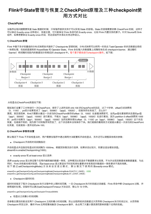
Flink中State管理与恢复之CheckPoint原理及三种checkpoint使⽤⽅式对⽐CheckPoint当程序出现问题需要恢复 Sate 数据的时候,只有程序提供⽀持才可以实现 State 的容错。
State 的容错需要依靠 CheckPoint 机制,这样才可以保证 Exactly-once 这种语义,但是注意,它只能保证 Flink 系统内的 Exactly-once,⽐如 Flink 内置⽀持的算⼦。
针对 Source和 Sink 组件,如果想要保证 Exactly-once 的话,则这些组件本⾝应⽀持这种语义。
1) CheckPoint 原理Flink 中基于异步轻量级的分布式快照技术提供了 Checkpoints 容错机制,分布式快照可以将同⼀时间点 Task/Operator 的状态数据全局统⼀快照处理,包括前⾯提到的 KeyedState 和 Operator State。
Flink 会在输⼊的数据集上间隔性地⽣成 checkpoint barrier,通过栅栏(barrier)将间隔时间段内的数据划分到相应的 checkpoint 中。
每个算⼦都会进⾏checkpoint 操作。
如下图:从检查点(CheckPoint)恢复如下图:假如我们设置了三分钟进⾏⼀次CheckPoint,保存了上述所说的 chk-100 的CheckPoint状态后,过了⼗秒钟,offset已经消费到(0,1100),pv统计结果变成了(app1,50080)(app2,10020),但是突然任务挂了,怎么办?莫慌,其实很简单,flink只需要从最近⼀次成功的CheckPoint保存的offset(0,1000)处接着消费即可,当然pv值也要按照状态⾥的pv值(app1,50000)(app2,10000)进⾏累加,不能从(app1,50080)(app2,10020)处进⾏累加,因为 partition 0 offset消费到 1000时,pv统计结果为(app1,50000)(app2,10000)当然如果你想从offset (0,1100)pv(app1,50080)(app2,10020)这个状态恢复,也是做不到的,因为那个时刻程序突然挂了,这个状态根本没有保存下来。
checkpoint的使用方法
checkpoint的使用方法标题,掌握Checkpoint的使用方法,提高工作效率。
在现代社会,人们经常面临着繁忙的工作和生活压力。
为了更好地管理时间和任务,许多人开始寻找各种方法来提高工作效率。
其中,使用Checkpoint是一种非常有效的方法。
本文将介绍Checkpoint的使用方法,帮助读者更好地利用这一工具来提高工作效率。
首先,什么是Checkpoint?Checkpoint是一种时间管理工具,它可以帮助人们将任务分解成小步骤,并设定时间节点来完成这些步骤。
通过这种方式,人们可以更好地掌控自己的工作进度,避免拖延和失控的情况发生。
要使用Checkpoint,首先需要明确自己的任务和目标。
将任务分解成小步骤,并为每个步骤设定一个时间节点。
这样一来,任务就会变得更加具体和可操作,而不是一团模糊的大任务。
例如,如果你的任务是写一篇文章,你可以将它分解成“收集资料”、“撰写大纲”、“写作初稿”、“修改”等步骤,并为每个步骤设定一个具体的时间。
其次,要合理安排时间。
在设定Checkpoint时,要考虑到自己的实际情况和工作习惯。
不要过于理想化地设定时间节点,以免造成压力和挫败感。
同时,也要考虑到任务的复杂程度和紧急程度,合理地安排时间节点。
最后,要严格执行Checkpoint。
设定好时间节点后,要努力按时完成每个步骤。
如果有一些步骤超出了时间节点,要及时调整,不要让拖延的情况发生。
另外,也要及时调整Checkpoint的设定,根据实际情况对任务进行重新分解和安排。
总的来说,Checkpoint是一种非常实用的时间管理工具,它可以帮助人们更好地掌控自己的工作进度,提高工作效率。
通过合理地设定时间节点和严格执行,人们可以更好地完成任务,减少拖延和失控的情况。
希望本文介绍的Checkpoint的使用方法能够帮助读者更好地应用这一工具,提高自己的工作效率。
python queue 基本用法
python queue 基本用法Python中的queue模块提供了一种实现线程安全的队列类型的方法。
队列是一种先进先出(FIFO)的数据结构,可以用于在多个线程之间进行数据交换。
本文将介绍queue模块的基本用法,以及如何使用队列进行线程间的通信。
概述队列(queue)是一种常用的数据结构,用于保存一系列的元素。
在队列中,新的元素被添加到队列尾部,而从队列中获取元素时,总是从队列头部开始。
这种先进先出(FIFO)的数据结构特性,使得队列在多线程编程中非常有用。
在Python中,queue模块提供了线程安全的队列类型。
queue模块实现了三种不同类型的队列:FIFOQueue、LifoQueue和PriorityQueue。
其中FIFOQueue和LifoQueue分别实现了先进先出队列和后进先出队列,PriorityQueue则基于元素的优先级进行排序。
使用queue模块可以方便地实现线程间的数据共享和通信。
队列提供了put()和get()方法,分别用于向队列中添加元素和从队列中获取元素。
这两个方法是原子操作,可以确保多线程环境下的数据安全。
FIFOQueue的基本用法FIFOQueue是queue模块中最常用的队列类型,它按照先进先出的顺序管理元素。
以下是FIFOQueue的基本用法示例:pythonfrom queue import Queue# 创建一个FIFOQueue对象q = Queue()# 向队列中添加元素q.put(1)q.put(2)q.put(3)# 从队列中获取元素print(q.get()) # 输出: 1print(q.get()) # 输出: 2print(q.get()) # 输出: 3通过导入`Queue`类,我们可以创建一个FIFOQueue对象。
使用`put()`方法可以向队列中添加元素,而使用`get()`方法可以从队列中获取元素。
这样,我们就可以实现多线程环境下的数据通信。
python中queue的queue类常用方法
python中queue的queue类常用方法一、简介Python中的Queue模块提供了一个线程安全的队列类,它可以帮助我们有效地管理数据,并在多线程环境中进行数据共享和通信。
Queue类提供了多种方法,使我们能够方便地使用队列。
二、Queue类常用方法1. **Queue()**:构造函数,创建一个新的空队列。
2. **put(item)**:向队列中添加一个元素。
如果队列已满,则此操作将阻塞,直到有空间可用。
3. **get()**:从队列中取出一个元素。
如果队列为空,则此操作将阻塞,直到有元素可用。
4. **task_done()**:标记一个任务(元素)的完成。
这是用于实现线程同步的一种方法。
5. **join()**:阻塞当前线程,直到队列中的所有元素都被处理完毕。
6. **empty**()和**full**():检查队列是否为空或已满。
7. **put_nowait()**和**get_nowait()**:这些是put()和get()的增强版本,它们会因为队列已满或队列为空而抛出异常,从而使得代码更易读且不易出错。
8. **put_bulk()**和**get_bulk()**:批量向队列中添加或从队列中获取元素。
9. **qsize()**:返回队列的大小。
三、示例下面是一个使用Queue的简单示例:```pythonimport queueimport threadingimport time# 创建一个队列对象q = queue.Queue()# 创建两个线程,一个用于添加元素,另一个用于获取元素def producer(q):for i in range(5):print('生产者添加元素: %s' % i)q.put(i) # 使用put方法添加元素time.sleep(1) # 模拟生产过程的耗时def consumer(q):while True:item = q.get() # 尝试获取元素if item is None: # 如果队列为空,获取操作会返回None,我们用它来标识任务的结束print('消费者完成任务')breakelse:print('消费者处理元素: %s' % item)q.task_done() # 使用task_done方法标记任务完成t1 = threading.Thread(target=producer, args=(q,))t2 = threading.Thread(target=consumer, args=(q,))t1.start() # 启动生产者线程t2.start() # 启动消费者线程t1.join() # 等待生产者线程结束q.join() # 等待队列中的所有任务结束,即所有元素都被处理完毕```以上代码创建了一个生产者和一个消费者线程,生产者向队列中添加元素,消费者从队列中获取并处理元素。
checkpoint模型原理
checkpoint模型原理
Checkpoint模型原理是一种训练过程中保存模型参数的方法,
可以在训练过程中定期保存模型的参数,并在需要时恢复训练过程。
该方法通常用于训练时间较长的模型,以防止训练过程中的意外中断导致之前训练的结果丢失。
在训练过程中,可以通过设置一个保存间隔来控制在多少个训练步骤后保存一次模型参数。
每次保存时,模型的参数会被序列化并保存在硬盘上,通常是保存为一个二进制文件。
在需要恢复训练的情况下,可以通过加载之前保存的模型参数来初始化模型,并从之前保存的步骤继续训练。
Checkpoint模型的实现通常依赖于特定的深度学习框架。
例如,在TensorFlow中,可以使用tf.train.Saver类来保存和恢复模型参数。
当调用Saver的save()方法时,当前的模型参数会被保
存为一个checkpoint文件;当调用Saver的restore()方法时,
可以通过指定checkpoint文件的路径来加载之前保存的模型参数。
Checkpoint模型在实际应用中非常有用,它可以帮助减少训练
过程中的风险,并且可以方便地在需要的时候恢复训练过程,节省时间和计算资源。
Python自带队列模块Queue的使用(1)

Python自带队列模块Queue的使用(1)Python自带队列模块Queue的使用(1)Python自带的queue模块是多线程编程中常用的数据结构之一,用于解决线程间的通信和数据同步问题。
queue模块提供了多种队列类型,包括FIFO队列、LIFO队列和优先级队列,可以根据不同的需求选择合适的队列类型。
在Python中,queue模块中最常用的队列类型是FIFO队列,即先进先出队列。
FIFO队列的特点是,先放入队列的元素先被取出,与现实生活中的排队现象类似。
下面将介绍queue模块的FIFO队列的使用方法。
首先,我们需要导入queue模块:```pythonimport queue```接下来,我们可以创建一个FIFO队列对象:```pythonq = queue.Queue```在创建队列对象之后,我们可以使用队列对象的put(方法往队列中放入元素,使用get(方法从队列中取出元素。
put(方法和get(方法都是阻塞方法,意味着如果队列已满或者队列为空时,put(方法和get(方法都会阻塞当前线程。
下面是一个简单的例子,展示了如何向队列中放入元素和从队列中取出元素:```pythonimport queueimport threadingdef producer(q):for i in range(5):q.put(i)print(f'Produced: {i}')def consumer(q):while True:item = q.getif item is None:breakprint(f'Consumed: {item}')q.task_doneq = queue.Queuet1 = threading.Thread(target=producer, args=(q,))t2 = threading.Thread(target=consumer, args=(q,))t1.startt2.startq.join```在上面的代码中,我们创建了一个队列对象q,并创建了两个线程,一个线程作为生产者使用put(方法向队列中放入元素,另一个线程作为消费者使用get(方法从队列中取出元素。
prometheuscheckpoint原理

prometheuscheckpoint原理Prometheus是一种开源的监控和警报工具,用于记录实时的度量数据,并且提供强大的查询和可视化功能。
Checkpoint是Prometheus提供的一种数据持久化机制,它可以将度量数据保存在磁盘上,以便于在Prometheus实例重启后能够恢复数据。
本文将详细介绍Prometheus Checkpoint的原理及其工作方式。
1. Checkpoint原理概述:在Prometheus中,度量数据的持久化通常通过检查点(Checkpoint)来实现。
检查点是指将数据写入磁盘,以便在Prometheus实例重启后能够恢复数据状态。
Checkpoint持久化机制的实现涉及到以下两个关键概念:快照(Snapshot)和日志(Write-Ahead Log,简称WAL)。
2. 快照(Snapshot):快照是指将当前时刻的所有数据写入磁盘的一个完整的副本。
这种方式非常适合用于在Prometheus重启后恢复整个数据集。
在执行快照过程中,Prometheus首先会将当前的内存数据集写入一个临时文件。
然后,它会将当前的指针位置也写入该文件,以便在恢复过程中能够定位到恢复位置。
最后,它会将该文件重命名为稳定的文件名,以确保在Prometheus重启后能够找到该文件。
快照的生成是有一定成本的,尤其在数据集很大的情况下。
因此,Prometheus默认情况下是以一定的时间间隔自动执行快照,以便在重启后能够快速地恢复数据。
3. 日志(Write-Ahead Log,WAL):WAL是一种预写日志,它用于记录Prometheus中每次发生的写入操作。
当写入操作发生时,Prometheus会将目标数据写入WAL,然后再将其写入内存中。
这样做的好处是,即使Prometheus在重启前发生崩溃,其数据仍然可以通过WAL进行恢复。
WAL的实现是通过文件系统的追加写入特性来实现的,即每次发生写入操作时,Prometheus会将数据以追加的方式写入一个文件。
- 1、下载文档前请自行甄别文档内容的完整性,平台不提供额外的编辑、内容补充、找答案等附加服务。
- 2、"仅部分预览"的文档,不可在线预览部分如存在完整性等问题,可反馈申请退款(可完整预览的文档不适用该条件!)。
- 3、如文档侵犯您的权益,请联系客服反馈,我们会尽快为您处理(人工客服工作时间:9:00-18:30)。
相关操作
select checkpoint_ from v$database
alter system checkpoint
alter system switch logfile
select name,checkpoint_change# from v$datafile
end;
select * from t2
alter system flush buffer_cache
select name,checkpoint_change# from v$datafile_header
select * from v$log;
begin
for i in 1..10000 loop
insert into t2 values(1,'xkj');
commit;
end loop;
1、检查点队列 checkpoint queue
rba
lrba
hrba
on disk rba
2、ckpt进程
每隔3秒钟触发一次
记录检查点信息
触发DBWR进程
3、增量检查点并不会去更新数据文件头,以及控制文件中数据库SCN以及数据文件条目的SCN信息,而只是每3秒由CKPT进程去更新控制文件中的low cache rba信息,也就是检查点的位置。
select CPDRT,CPLRBA_SEQ||'.'||CPLRBA_BNO||'.'||CPLRBA_BOF "Low
RBA",CPODR_SEQ||'.'||CPODR_BNO||'.'||CPODR_BOF "On disk RBA",CPODS,CPODT,CPHBT from x$kcccp;
CPDRT列是检查点队列中的脏块数目.
CPODS列是on disk rba的scn
CPODT列是on disk rba的时间戳
CPHBT列是心跳
如果发生了实例崩溃,只需要在日志文件中找到检查点位置(low cache rba),从此处开始应用所有的重做日志文件,就完成了前滚操作。实例崩溃后,再次启动数据库,oracle会到控制文件中读取low cache rba,这就是检查点位置。从此处开始应用重做日志,应用到on disk rba的位置。on disk rba是磁盘中重做日志文件的最后一条重做记录的rba。
