VSBU-150-9中文资料
现代挖掘机150w-9
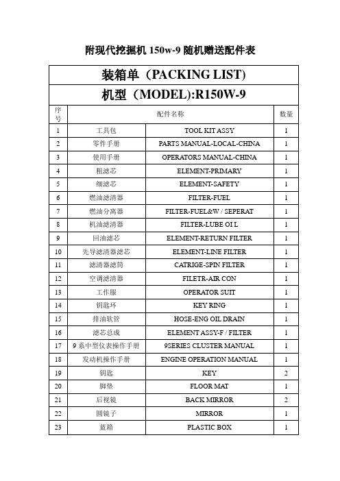
附现代挖掘机150w-9随机赠送配件表装箱单(PACKING LIST)机型(MODEL):R150W-9序配件名称数量号1 工具包TOOL KIT ASSY 12 零件手册PARTS MANUAL-LOCAL-CHINA 13 使用手册OPERATORS MANUAL-CHINA 14 粗滤芯ELEMENT-PRIMARY 15 细滤芯ELEMENT-SAFETY 16 燃油滤清器FILTER-FUEL 17 燃油分离器FILTER-FUEL&W / SEPERAT 18 机油滤清器FILTER-LUBE OI L 19 回油滤芯ELEMENT-RETURN FILTER 110 先导滤清器滤芯ELEMENT-LINE FILTER 111 滤清器滤筒CATRIGE-SPIN FILTER 112 空调滤清器FILETR-AIR CON 113 工作服OPERATOR SUIT 114 钥匙环KEY RING 115 排油软管HOSE-ENG OIL DRAIN 116 滤芯总成ELEMENT ASSY-F / FILTER 117 9系中型仪表操作手册9SERIES CLUSTER MANUAL 118 发动机操作手册ENGINE OPERATION MANUAL 119 钥匙KEY 220 脚垫FLOOR MAT 121 后视镜BACK MIRROR 222 圆镜子MIRROR 123 蓝箱PLASTIC BOX 1现代R150W-9性能描述区分内容高端设计外观及Interior 采用新设计体现了装备的高端化对应环保规定安装低排量,环境亲和性TIER 2 发动机,对应环保规定提高装备操作应对性及冷却性能提高了装备操作(作业装置)应对性及庄内冷却性能适用AL Radiator & Cooler,提高冷却效率提高驾驶舒适度增加了机械电子装置及舒适的设施,提高了驾驶的舒适性后方摄像机,大型监视器(7”),Auto A/C, Mp3 Player耐久性及维修费用提高装备耐久性及减少维修费用适用烧结轴套(250hr),适用长寿命启动油。
2N5551中文资料(fairchild)中文数据手册「EasyDatasheet - 矽搜」
50 VCB = 100V
10
10
10
1β
100 Co
o
125 C
0.1
o
-40 Co
25 Co
75 C
- CCEO(SALT)LECTOR-EMITTER VOLTAGE [V]
0.01
V
1
10
100
IC- COLLECTOR CURRENT [mA]
Figure 2. Collector-Emitter Saturation Voltage vs.
芯片中文手册,看全文,戳
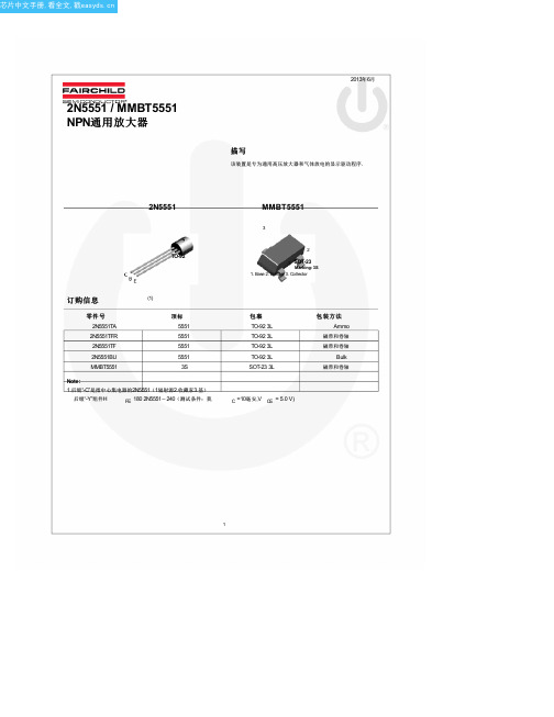
2N5551 / MMBT5551 NPN通用放大器
2013年6月
描写
该装置是专为通用高压放大器和气体放电的显示驱动程序.
2N5551
TO-92
MMBT5551
3
2
1 SOT-23
Marking: 3S 1. Base 2. Emitter 3. Collector
MMBT5551
350 2.8
357
Units
mW mW/°C °C/W °C/W
2
芯片中文手册,看全文,戳
电气特性
(4)
价值观是在T 符
A = 25°C除非另有说明. 参数
断特性
V(BR)CEO 集电极 - 发射极击穿电压 V(BR)CBO 集电极基击穿电压 V (BR)EBO 发射极基极击穿电压
Value
160 180
6 600 -55到+150
2N5551 / MMBT5551 - NPN通用放大
器
Units
V V V mA °C
热特性
价值观是在T
BUK98150-55A中文资料
© Koninklijke Philips Electronics N.V. 2002. All rights reserved.
2 of 12
Philips Semiconductors
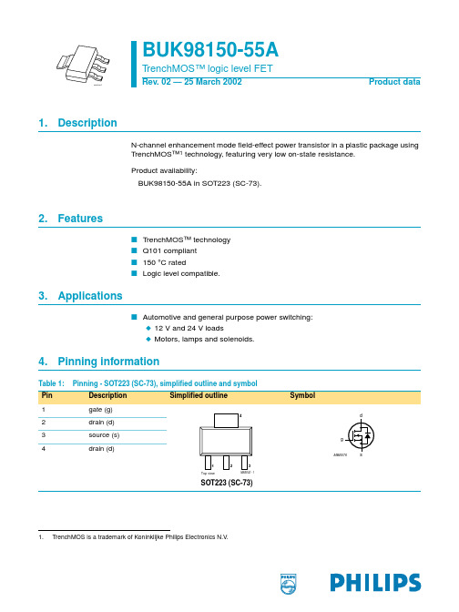
BUK98150-55A
TrenchMOS™ logic level FET
120 Pder
(%)
80
03aa17
starting Tj = 25 °C
Max Unit
55
V
5
A
8
W
150
°C
150
mΩ
161
mΩ
137
mΩ
Max Unit
55
V
55
V
±15
V
5
A
3
A
22
A
8
W
+150 °C
+150 °C
5
A
22
A
31
mJ
9397 750 09435
Product data
Rev. 02 — 25 March 2002
Tsp = 25 °C; Figure 1
-
Tstg
storage temperature
−55
Tj
operating junction temperature
−55
Source-drain diode
IDR
reverse drain current (DC)
Tsp = 25 °C
-
IDRM
peak reverse drain current
128
VGS = 4.5 V; ID = 5 A
工厂专有名词中英文对照表
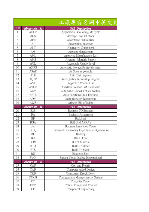
Contract Electronic Manufacturing Customer Focus Executive Cost,Insurance,and Freight Carriage and Insurance Paid TO Common Management Information Protocol Cost of Goods Sold Component Purchase Agreement Carriage Paid to Change Request Customer Service Division Customer Selling Price Configure To Order Full Descripition Delivered At Frontier Document Center Delivered Duty Paid Delivered Duty Unpaid Design For Assembly Design For Manufacture Dead on Arrival Defect Per Hunderd Unit Defect Per Percent Million Dynamic Random Access Memory Design For Test Design For X(test,manufacture,assembly) Dual in-line Package Domain Name System Defect per Million Desktop Design TO Cost Design Verification Test Full Descripition End to End Engineering Change Engineering Change Management Engineering Change Notice Engineering Change Order Engineering Change Request Engineering Directive Enhanced Industrial Standard Architecture Early Life Performance Test Environment Protection Association Erasable Programable Read Only Memory Engineering Specification
u-blox D9纠正数据接收器数据手册说明书

NEO-D9S-00Bu-blox D9 correction data receiverData sheetAbstractTechnical data sheet describing the u-blox D9 correction data receiver.The module provides global and easy access to satellite L-band GNSScorrections.UBX-18012996 - R07C1-PublicDocument informationTitle NEO-D9S-00BSubtitle u-blox D9 correction data receiverDocument type Data sheetDocument number UBX-18012996Revision and date R0724-Jan-2022 Disclosure restriction C1-PublicProduct status Corresponding content statusIn development /Objective specification Target values. Revised and supplementary data will be published later. prototypeEngineering sample Advance information Data based on early testing. Revised and supplementary data will bepublished later.Initial production Early production information Data from product verification. Revised and supplementary data may bepublished later.Mass production /Production information Document contains the final product specification.End of lifeThis document applies to the following products:Product name Type number FW version IN/PCN reference Product statusNEO-D9S NEO-D9S-00B-00PMP 1.04UBX-22001724Mass productionu-blox or third parties may hold intellectual property rights in the products, names, logos and designs included in this document. Copying, reproduction, modification or disclosure to third parties of this document or any part thereof is only permitted with the express written permission of u-blox.The information contained herein is provided "as is" and u-blox assumes no liability for its use. No warranty, either express or implied, is given, including but not limited to, with respect to the accuracy, correctness, reliability and fitness for a particular purpose of the information. This document may be revised by u-blox at any time without notice. For the most recent documents, visit .Copyright © 2022, u-blox AG.Contents1 Functional description (4)1.1 Overview (4)1.2 Performance (4)1.3 Supported GNSS augmentation systems (4)1.3.1 Satellite L-band (4)1.4 Supported protocols (5)2 System description (6)2.1 Block diagram (6)3 Pin definition (7)3.1 Pin assignment (7)4 Electrical specification (9)4.1 Absolute maximum ratings (9)4.2 Operating conditions (9)4.3 Indicative power requirements (10)5 Communications interfaces (11)5.1 UART (11)5.2 SPI (11)5.3 I2C (12)5.4 USB (13)5.5 Default interface settings (14)6 Mechanical specification (15)7 Reliability tests and approvals (16)7.1 Approvals (16)8 Labeling and ordering information (17)8.1 Product labeling (17)8.2 Explanation of product codes (17)8.3 Ordering codes (17)Related documents (18)Revision history (19)1 Functional description1.1 OverviewNEO-D9S-00B is a satellite data receiver for L-band correction broadcast, which can be configured for use with a variety of correction services. It decodes the satellite transmission and outputs a correction stream, enabling a high precision GNSS receiver to reach accuracies down to centimeter level.1.2 PerformanceParameter SpecificationReceiver type NEO-D9S correction data receiverL-band satellite SpecificationTime to first frame 1< 10 s at 2400 bpsSensitivity acquisition 2-133 dBm for BER <10e-5 at 2400 bit/sSpecification compliance L-band SESTB28ABoot time<1 sCenter frequency configuration steps 1 HzCenter frequency search window0 to 65 kHzUser data rates600, 1200, 2400, 4800 bpsService identifier ConfigurableDe-scrambler ConfigurableDe-scrambling initialization vector ConfigurablePre-scrambler Enable/disableNumber of concurrent reception1channelsUniqueWord ConfigurableFrequency range1525 MHz to 1559 MHzCommunication interface UART/USB/I2C/SPICommunication speed Up to 921600 baud UART, USB 2.0Software back-up mode AvailableDynamics+/- 2g acceleration for all data rates (600 bit/s, 1200 bit/s, 2400 bit/s,4800 bit/s)Vehicle dynamicsVelocity Up to and including 300 km/hTable 1: NEO-D9S-00B performance1.3 Supported GNSS augmentation systems1.3.1 Satellite L-bandThe satellite L-band communication system allows GNSS correction service providers to broadcast a variety of services on specific channels, satellites and beams. Consult your service provider on the region their service covers and the specific frequency used. The NEO-D9S-00B must be configured1With respect to an L-band signal using a 20-25 dB external LNA2Success rate of acquiring an L-band signal > 95% using a 20-25 dB external LNAaccording to the specific service as initial identification and decoding of the service provider stream is required.1.4 Supported protocolsThe NEO-D9S-00B supports the following protocols:Protocol TypeUBX Input/output, binary, u-blox proprietaryTable 2: Supported protocolsFor specification of the protocols, see the interface description [2].2 System description2.1 Block diagramFigure 1: NEO-D9S-00B block diagramAn active antenna is mandatory with the NEO-D9S-00B.3 Pin definition3.1 Pin assignmentThe pin assignment of the NEO-D9S-00B module is shown in Figure 2. The defined configuration of the PIOs is listed in Table 3.Figure 2: NEO-D9S-00B pin assignmentPin I/O Description1SAFEBOOT_N I SAFEBOOT_N (used for FW updates and reconfiguration, leave open) 2D_SEL I UART 1 / SPI select. (open or high = UART 1)3TXD2O UART 2 TXD4RXD2I UART 2 RXD5USB_DM I/O USB data (DM)6USB_DP I/O USB data (DP)7V_USB I USB supply8RESET_N I RESET (active low)9VCC_RF O External LNA power10GND I Ground11RF_IN I Active antenna L-band signal input12GND I Ground13GND I Ground14ANT_OFF O External LNA disable - default active highPin I/O Description15ANT_DETECT I Active antenna detect - default active high16ANT_SHORT_N O Active antenna short detect- default active low17EXTINT I External interrupt pin18SDA / SPI CS_N I/O I2C data if D_SEL = VCC (or open); SPI chip select if D_SEL = GND 19SCL / SPI SLK I/O I2C clock if D_SEL = VCC (or open); SPI clock if D_SEL = GND20TXD / SPI MISO O UART1 output if D_SEL = VCC (or open); SPI MISO if D_SEL = GND 21RXD / SPI MOSI I UART1 input if D_SEL = VCC (or open); SPI MOSI if D_SEL = GND 22V_BCKP I Connect to VCC or leave it open23VCC I Supply voltage24GND I GroundTable 3: NEO-D9S-00B pin assignmentFor detailed information on the pin functions and characteristics see the integrationmanual [1].4 Electrical specificationThe limiting values given are in accordance with the Absolute Maximum Rating System(IEC 134). Stress above one or more of the limiting values may cause permanent damage to the device. These are stress ratings only. Operation of the device at these or at any other conditions above those given below is not implied. Exposure to limiting values for extended periods may affect device reliability.Where application information is given, it is advisory only and does not form part of thespecification.4.1 Absolute maximum ratingsParameter Symbol Condition Min Max Units Power supply voltage VCC-0.5 3.6VVoltage ramp on VCC3208000µs/VInput pin voltage Vin-0.5VCC + 0.5VVCC_RF output current ICC_RF100mASupply voltage USB V_USB–0.5 3.6V-0.5V_USB + 0.5VUSB signals USB_DM,USB_DP10dBmInput power at RF_IN Prfin source impedance =50 Ω, continuous waveStorage temperature Tstg-40+85°CTable 4: Absolute maximum ratingsThe product is not protected against overvoltage or reversed voltages. Voltage spikesexceeding the power supply voltage specification, given in the table above, must be limited to values within the specified boundaries by using appropriate protection diodes.4.2 Operating conditionsAll specifications are at an ambient temperature of 25 °C. Extreme operating temperatures can significantly impact the specification values. Applications operating near thetemperature limits should be tested to ensure the specification.Parameter Symbol Min Typical Max Units Condition Power supply voltage VCC 2.7 3.0 3.6VSW backup current I_SWBCKP0.36mAInput pin voltage range Vin0VCC VDigital IO pin low level input voltage Vil0.4VDigital IO pin high level input voltage Vih0.8 * VCC VDigital IO pin low level output voltage Vol0.4V Iol = 2 mA Digital IO pin high level output voltage Voh VCC – 0.4V Ioh = 2 mAIpin5mADC current through any digital I/O pin(except supplies)VCC_RF voltage VCC_RF VCC - 0.1VVCC_RF output current ICC_RF50mA3Exceeding the ramp speed may permanently damage the deviceParameter Symbol Min Typical Max Units Condition Receiver chain noise figure4NFtot11dBRecommended LNA gain into module LNA_gain20dBOperating temperature Topr-40+2585°CTable 5: Operating conditionsOperation beyond the specified operating conditions can affect device reliability.4.3 Indicative power requirementsTable 6 lists examples of the total system supply current including RF and baseband section for a possible application.Values in Table 6 are provided for customer information only, as an example of typicalcurrent requirements. The values are characterized on samples by using a cold startcommand. Actual power requirements can vary depending on FW version used, externalcircuitry, number of satellites tracked, signal strength, type and time of start, duration, and conditions of test.Unit Symbol Parameter Conditions L - bandSESTB28AI PEAK Peak current Acquisition & tracking130mAI AVERAGE Average current Acquisition & tracking35mATable 6: Currents to calculate the indicative power requirementsAll values in Table 6 are measured at 25 °C ambient temperature.4Only valid for the L-band band5 Communications interfacesThere are several communications interfaces including UART, SPI, I2C5 and USB.5.1 UARTUART1 is the main UART interface for UBX protocol host control and message output.Symbol Parameter Min Max UnitR u Baud rate9600921600bit/sΔTx Tx baudrate accuracy-1%+1%-ΔRx Rx baudrate tolerance-2.5%+2.5%-Table 7: NEO-D9S-00B UART specifications5.2 SPIThe NEO-D9S-00B has an SPI slave interface that can be selected by setting D_SEL = 0. The SPI slave interface is shared with UART1. The SPI pins available are: SPI_MISO (TXD), SPI_MOSI (RXD), SPI_CS_N, SPI_CLK. The SPI interface is designed to allow communication to a host CPU. The interface can be operated in slave mode only. Note that SPI is not available in the default configuration because its pins are shared with the UART1 and I2C interfaces. The maximum transfer rate using SPI is 125 kB/s and the maximum SPI clock frequency is 5.5 MHz.This section provides SPI timing values for the NEO-D9S-00B slave operation. The following tables present timing values under different capacitive loading conditions. Default SPI configuration is CPOL = 0 and CPHA = 0.Figure 3: NEO-D9S-00B SPI specification mode 1: CPHA=0 SCK = 5.33 MHzTimings 1 - 12 are not specified here.Timing value at 2 pF load Min (ns)Max (ns)"A" - MISO data valid time (CS)14385I2C is a registered trademark of Philips/NXPTiming value at 2 pF load Min (ns)Max (ns)"B" - MISO data valid time (SCK) weak driver mode2138"C" - MISO data hold time114130"D" - MISO rise/fall time, weak driver mode14"E" - MISO data disable lag time2032Table 8: NEO-D9S-00B SPI timings at 2pF loadTiming value at 20 pF load Min (ns)Max (ns)"A" - MISO data valid time (CS)1952"B" - MISO data valid time (SCK) weak driver mode2551"C" - MISO data hold time117137"D" - MISO rise/fall time, weak driver mode616"E" - MISO data disable lag time2032Table 9: NEO-D9S-00B SPI timings at 20pF loadTiming value at 60 pF load Min (ns)Max (ns)"A" - MISO data valid time (CS)2979"B" - MISO data valid time (SCK) weak driver mode3578"C" - MISO data hold time122152"D" - MISO rise/fall time, weak driver mode1541"E" - MISO data disable lag time2032Table 10: NEO-D9S-00B SPI timings at 60pF load5.3 I2CAn I2C compliant interface is available for communication with an external host CPU. The interface can be operated in slave mode only. It is fully compatible with the I2C industry standard fast mode. Since the maximum SCL clock frequency is 400 kHz, the maximum bit rate is 400 kbit/s. The interface stretches the clock when slowed down while serving interrupts, therefore the real bit rates may be slightly lower.The I2C interface is only available with the UART default mode. If the SPI interface isselected by using D_SEL = 0, the I2C interface is not available.Figure 4: NEO-D9S-00B I2C slave specificationMax Unit Symbol Parameter Min (Standard /Fast mode)f SCL SCL clock frequency0400kHzt HD;STA Hold time (repeated) START condition 4.0/1-µst LOW Low period of the SCL clock5/2-µst HIGH High period of the SCL clock 4.0/1-µst SU;STA Set-up time for a repeated START condition5/1-µst HD;DAT Data hold time0/0-µst SU;DAT Data set-up time250/100nst r Rise time of both SDA and SCL signals-1000/300 (for C 400pF)nst f Fall time of both SDA and SCL signals-300/300 (for C 400pF)nst SU;STO Set-up time for STOP condition 4.0/1-µst BUF Bus-free time between a STOP and START5/2-µs conditiont VD;DAT Data-valid time-4/1µst VD;ACK Data-valid acknowledge time-4/1µsV nL Noise margin at the low level0.1 VCC-VV nH Noise margin at the high level0.2 VCC-VTable 11: NEO-D9S-00B I2C slave timings and specifications5.4 USBThe USB 2.0 FS (Full Speed, 12 Mbit/s) interface can be used for host communication. Due to the hardware implementation, it may not be possible to certify the USB interface. The V_USB pinsupplies the USB interface.5.5 Default interface settingsInterface SettingsUART9600 baud, 8 bits, no parity bit, 1 stop bit.Output protocol: UBX.Input protocols without need of additional configuration: UBX.USB Output messages activated as in UART. Input protocols available as in UART.I2C Output messages activated as in UART. Input protocols available as in UART.SPI Output messages activated as in UART. Input protocols available as in UART.Table 12: Default interface settingsThe boot message is still output using $GNTXT messages. The messages are output when the NEO-D9S-00B is powered up.Refer to the applicable interface description [2] for information about further settings.6 Mechanical specificationFigure 5: NEO-D9S-00B mechanical drawingSymbol Min (mm)Typical (mm)Max (mm) A15.916.016.6B12.112.212.3C 2.2 2.4 2.6D0.9 1.0 1.3E 1.0 1.1 1.2F 2.9 3.0 3.1G0.9 1.0 1.3H0.720.820.92K0.70.80.9M0.80.9 1.0N0.40.50.6 Weight 1.6gTable 13: NEO-D9S-00B mechanical dimensions7 Reliability tests and approvalsNEO-D9S-00B modules are based on AEC-Q100 qualified GNSS chips.Tests for product family qualifications are according to ISO 16750 "Road vehicles – environmental conditions and testing for electrical and electronic equipment”, and appropriate standards.7.1 ApprovalsThe NEO-D9S-00B is designed to in compliance with the essential requirements and otherrelevant provisions of Radio Equipment Directive (RED) 2014/53/EU.The NEO-D9S-00B complies with the Directive 2011/65/EU (EU RoHS 2) and its amendmentDirective (EU) 2015/863 (EU RoHS 3).Declaration of Conformity (DoC) is available on the u-blox website.8 Labeling and ordering informationThis section provides information about product labeling and ordering. For information about moisture sensitivity level (MSL), product handling and soldering see the integration manual [1]. 8.1 Product labelingThe labeling of the NEO-D9S-00B modules provides product information and revision information. For more information contact u-blox sales.8.2 Explanation of product codesThree product code formats are used. The Product name is used in documentation such as this data sheet and identifies all u-blox products, independent of packaging and quality grade. The Ordering code includes options and quality, while the Type number includes the hardware and firmware versions.Table 14 below details these three formats.Format Structure Product codeProduct name PPP-TGV NEO-D9SOrdering code PPP-TGV-NNQ NEO-D9S-00BType number PPP-TGV-NNQ-XX NEO-D9S-00B-00Table 14: Product code formatsThe parts of the product code are explained in Table 15.Code Meaning ExamplePPP Product family NEOTG Platform D9 = u-blox D9V Variant S = L-band correctionsNNQ Option / Quality grade NN: Option [00...99]Q: Grade, A = Automotive, B = ProfessionalXX Product detail Describes hardware and firmware versionsTable 15: Part identification code8.3 Ordering codesOrdering code Product RemarkNEO-D9S-00B NEO-D9S correction data receiver u-blox D9 correction data receiver for L-bandbroadcastTable 16: Product ordering codesProduct changes affecting form, fit or function are documented by u-blox. For a list ofProduct Change Notifications (PCNs) see our website at: https:///en/product-resources.Related documents[1]NEO-D9S Integration manual UBX-19026111[2]PMP 1.04 Interface description UBX-21040023For regular updates to u-blox documentation and to receive product change notifications please register on our homepage https://.Revision historyRevision Date Name Status / commentsR0126-Mar-2018jhak Objective SpecificationR0226-Apr-2019jhak Objective SpecificationR0328-June-2019ghun Objective Specification - V_BCKP removedR0426-Nov-2019ghun/jhak Advance Information - V_BCKP pin connect to VCC. I2C, SPI, antennasupervisor, EXTINT, software back-up mode added.R0505-Feb-2020ghun/jhak Early production information - USB added to Absolute maximun ratingstable. Vil and Vih updated in Operating conditions table.R0627-Oct-2020dama USB Interface section update. UART interface section updateR0724-Jan-2022dama Production information - Voltage ramp on VCC value added in Absolutemaximum ratings table. V_BCKP gerenal update.ContactFor complete contact information visit us at .u-blox OfficesNorth, Central and South America Headquarters Asia, Australia, PacificEurope, Middle East, Africau-blox America, Inc.u-blox AG u-blox Singapore Pte. Ltd.Phone:+1 703 483 3180Phone:+41 44 722 74 44Phone:+65 6734 3811E-mail:******************E-mail:***************E-mail:******************Support:******************Support:********************* Regional Office West Coast Regional Office AustraliaPhone:+1 408 573 3640 Phone:+61 3 9566 7255E-mail:****************** E-mail:*******************Support:********************* Technical Support Regional Office China (Beijing) Phone:+1 703 483 3185 Phone:+86 10 68 133 545E-mail:********************* E-mail:******************Support:********************* Regional Office China (Chongqing) Phone:+86 23 6815 1588E-mail:******************Support:********************* Regional Office China (Shanghai)Phone:+86 21 6090 4832E-mail:******************Support:********************* Regional Office China (Shenzhen) Phone:+86 755 8627 1083E-mail:******************Support:********************* Regional Office IndiaPhone:+91 80 4050 9200E-mail:******************Support:********************* Regional Office Japan (Osaka)Phone:+81 6 6941 3660E-mail:******************Support:********************* Regional Office Japan (Tokyo)Phone:+81 3 5775 3850E-mail:******************Support:********************* Regional Office KoreaPhone:+82 2 542 0861E-mail:******************Support:********************* Regional Office TaiwanPhone:+886 2 2657 1090E-mail:******************Support:*********************。
罗克韦尔 Compact 5000 I O 数字量模块 说明书

基于 EtherNet/IP 的连接 . . . . . . . . . . . . . . . . . . . . . . . . . . . . . . . . . . . 56 使用 External Means 时连接的其他注意事项 . . . . . . . . . . . . . . . . 57 受限操作 . . . . . . . . . . . . . . . . . . . . . . . . . . . . . . . . . . . . . . . . . . . . . . . . . . . . . . . 58 安全模块特定注意事项 . . . . . . . . . . . . . . . . . . . . . . . . . . . . . . . . . . . . . . . . 59 整体系统安全功能 . . . . . . . . . . . . . . . . . . . . . . . . . . . . . . . . . . . . . . . . . 60 单通道或双通道模式 . . . . . . . . . . . . . . . . . . . . . . . . . . . . . . . . . . . . . . . 60 与安全控制器结合使用 . . . . . . . . . . . . . . . . . . . . . . . . . . . . . . . . . . . . 61 确定符合性 . . . . . . . . . . . . . . . . . . . . . . . . . . . . . . . . . . . . . . . . . . . . . . . . 61
DL750 ScopeCorder G 商品说明书
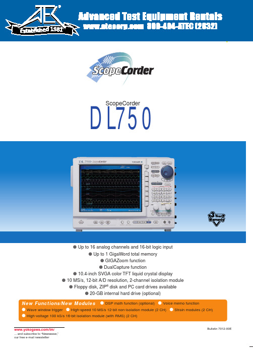
Leading-Edge Mounting Technology and ASICs Reduce the Size of 2-Channel Modules Modules701250701251701255701260701265701270701271s High-Speed 10 MS/s 12-Bit Isolation Module (701250) Broad bandwidth (3 MHz) and high accuracy (0.5%) inputs s High-Speed 1 MS/s 16-Bit Isolation Module (701251) High resolution inputs combined with high-sensitivity (1 mV/ div)s Temperature/High-Precision Voltage Module (701265) 100 Hz frequency range, high-accuracy (0.08%) voltage measurements, and an ultra high-sensitivity range value (100µV/div)s High-Speed 10 MS/s 12-Bit Non-Isolation Module (701255)Non-isolated model with the same performance as the model 701250s High-Voltage 100 kS/s 16-Bit Isolation Module (with RMS) (701260)850 V (DC+ACpeak) direct input, RMS mode Accuracy of 0.25%s Strain Modules (701270 & 701271)NDIS-type (701270) and DSUB-type (701271)Wide range of bridge voltages (2 V, 5 V, & 10 V) Accuracy of 0.5%4 new modules for a variety of applicationsN E WN E WN E W2DualCapture: A Powerful Tool for Durability Test Data AnalysisThe waveform shown above was captured at a sampling rate of 50 kS/s. The occurrence of noise can be confirmed in the graph, but the time resolution is too low to capture the waveform accurately.With DualCapture, the user sets triggers for capturing sudden phenomena. Up to 100 phenomena can be collected in a memory length of 10 kW at a maximum sampling rate of 10 MS/s.10 kWPhenomena canbe accuratelyassessed at 10MS/s Maximum 100 phenomenaRoll-mode viewUser-specified captured screen and thecorresponding time are displayed.This is the limit for 50 kS/s.phenomenonMaximum 100 MWA Wide Range of Trigger Functions for Accurately Capturing a Variety of WaveformsHaving a wide range of triggers is of course very useful for obtaining stable observations of variety of different waveforms. In Action-On TriggerAutomatically Save Measured Data When this trigger is activated, the DL750performs a specified action each time a waveform is captured and displayed on the screen. This feature is useful for saving data automatically and reliably (e.g., for data collection in automated, continuous tests).Manual TriggerA Trigger Can Be Activated with Press of a Button.With this feature, a trigger can be executed whenever you like,separate from the preset trigger conditions.riggers the n-th time that condition B goes true after condition riggers if condition B goes true after condition A has gone true and an interval at least equal to the delay setting has elapsed. Activates an edge trigger on another input during the interval riggers when any one of the individual channel conditions set riggers when a preset waveform frequency condition goes true.Triggers when a trigger source enters or leaves a level set by two points Triggers when a signal leaves an automatically-defined "wave window"Multi-Channel 2-Location Zoom FunctionGO/NO-GO Judgmentscreenshot to a specified destination, saving waveform data to a specified storage medium, sounding a buzzer, and6Display and Data Recording FunctionsReal-Time Hard Drive Recording (with the /C8 Option)Recorder-Like Real-Time Data Recording over Extended PeriodsWith the optional internalhard drive, you can record measurements to the harddrive in real time. Thismakes it easier to manage and analyze data usingPCs and other tools.Maximum data capacity:1 GWMaximum sampling rate:100 kS/s(using 1 channel only)Memory Backup FunctionProtects Your Data Even If the Power Supply Goes Out This function backs up about 10 hours of data saved to the acquisition memory immediately prior to power loss. Memory backup helps you avoid losing important data even if the power supply is unstable and gets cut off.(Backup time varies according to the usage environment. Four AA batteries are required for memory backup.)Snapshot FunctionEnables On-Screen Waveform Comparisons Using the snapshot function, you can keep the currently displayed waveform with the touch of a button. Snapshots are useful for comparing a reference waveform with an input waveform. In addition, snapshots can be saved to and loaded from the storage media.X-Y Display FunctionDisplay an Overlay of up to Four X-Y Displays This function lets you display multiple X-Y plots together,making relative phase comparisons easy. The X-Y display function is a powerful tool for applications such asevaluating DC motors based on a Lissajous waveform.All-Channel Setup MenuQuickly View the Setup of All ChannelsThis menu lets you review and modify all of the channel setups from a single screen display. Parameters such as voltage axis sensitivity, screen scale settings, and linear scaling can be configured for each channel.Wide Waveform DisplayIncrease the Viewing Area of DisplayWith the SVGA color TFT liquid crystal display, the number of display pixels has been greatly increased. For wide waveform display, set the resolution to 750 × 512 pixels.Volume control for recording andwaveform can be viewed on anUSBBasic 6.0 to control the DL750 through a USB interface.• Connecting USB Peripheral EquipmentUSB keyboards, USB mouse and USB printers can bedirectly connected to the DL750.Thumbnail displayUSB printer, or a network printer.operation using Internet Explorer.Data CaptureThis function downloads values of waveform parameters periodically, launches MS Excel and graphs the parameters on a spreadsheet values. This enables you to check the Measurement TrendUsing Internet Explorer,you can periodically or manually download screen images to a PC for remote waveform monitoring. Y ou can also download waveform data,start or stop ameasurement, or setup a split display all from a PC.Software for Waveform Measurement on a PC Software for Remotely Controlling the DL SeriesThe Wirepuller software program displays a screen image of the DL on your PC so that you can monitor waveform signals.In addition, you can use the PC’s mouse and keyboard to control the DL. The DL can be controlled via an Ethernet, USB, or GP-IB.This software program can be downloaded from the following URL (requires registration):/tm/Bu/DLsoft/wire/A trial version of this software program can be downloaded from the following URL:/tm/Bu/700919/Plug-In Module SpecificationsHigh-Speed 10 MS/s 12-Bit Isolation Module (701250)Input channels2Input couplings AC, DC, GNDMaximum sampling rate10 MS/sA/D conversion resolution12 bits (150 LSB/div)Input type Isolated unbalancedFrequency range(–3 dB)1DC, up to 3 MHzInput range(10:1)50 mV/div to 200 V/div (in steps of 1, 2, or 5),(1:1) 5 mV/div to 20 V/div (in steps of 1, 2, or 5) Effective measurement range20 div (display range: 10 div)DC offset±5 divMaximum input voltage (1 kHz or less)In combination with 700929 (10:1) 2600 V (DC + ACpeak)Direct input (1:1) 6, 10250 V (DC + ACpeak)Maximum allowable in-phase voltageIn combination with 700929 (10:1) 3400 Vrms (CA T I), 300 Vrms (CA T II) In combination with 7019in steps of 1, 2, or 5+701954 (1:1) 9400 Vrms (CA T I), 300 Vrms (CA T II) Main unit only (1:1) 1142 V (DC + ACpeak) (CA T I and CAT II, 30 Vrms) DC accuracy1±(0.5% of 10 div)Input impedance 1 MΩ± 1%, approx. 35 pFConnector type Isolation type BNC connectorInput filter OFF, 500 Hz, 5 kHz, 50 kHz, 500 kHz Temperature coefficientZero point±(0.05% of 10 div)/°C (typical value)Gain±(0.02% of 10 div)/°C (typical value)High-Speed 1 MS/s 16-Bit Isolation Module (701251)Input channels2Input couplings AC, DC, GNDMaximum sampling rate 1 MS/sA/D conversion resolution16 bits (2400 LSB/div)Input type Isolated unbalancedFrequency range (–3 dB)1DC, up to 300 kHz (20 V/div to 5 mV/div)Input range(10:1)10 mV/div to 200 V/div (in steps of 1, 2, or 5)(1:1) 1 mV/div to 20 V/div (in steps of 1, 2, or 5) Maximum input voltage (1 kHz or less)In combination with 700929 (10:1) 2600 V (DC + ACpeak)Direct input (1:1) 6, 10140 V (DC + ACpeak)Maximum allowable in-phase voltageIn combination with 700929 (10:1) 3400 Vrms (CA T I), 300 Vrms (CA T II) In combination with 701901+701954 (1:1) 9400 Vrms (CA T I), 300 Vrms (CA T II)Main unit only (1:1) 1142 V (DC + ACpeak) (CA T I and CAT II, 30 Vrms) DC accuracy15 mV/div to 20 V/div±(0.25% of 10 div)2 mV/div±(0.3% of 10 div)1 mV/div±(0.5% of 10 div)Input impedance 1 MΩ± 1%, approx. 35 pFConnector type Isolated type BNC connectorInput filter OFF, 400 Hz, 4 kHz, 40 kHzTemperature coefficientZero point 5 mV/div to 20 V/div: ±(0.02% of 10 div)/°C (typical value)2 mV/div: ±(0.05% of 10 div)/°C (typical value)1 mV/div: ±(0.10% of 10 div)/°C (typical value)Gain 1 mV/div to 20 V/div: ±(0.02% of 10 div)/°C (typical value) High-Speed 10 MS/s 12-Bit Non-Isolation Module (701255)Input channels2Input couplings AC, DC, GNDMaximum sampling rate10 MS/sA/D conversion resolution12 bits (150 LSB/div)Input type Non-isolated unbalancedFrequency range (–3 dB)1DC, up to 3 MHzInput range(10:1)50 mV/div to 200 V/div (in steps of 1, 2, or 5)(1:1) 5 mV/div to 20 V/div (in steps of 1, 2, or 5) Effective measurement range20 div (display range 10 div)DC offset±5 divMaximum input voltage (1 kHz or less)In combination with 701940 (10:1)600 V (DC + ACpeak)Direct input (1:1)250 V (DC + ACpeak)DC accuracy1±(0.5% of 10 div)Input impedance 1 MΩ± 1%, approx. 35 pFConnector type Metal type BNC connectorInput filter OFF, 500 Hz, 5 kHz, 50 kHz, 500 kHz Temperature coefficientZero point±(0.05% of 10 div)/°C (typical value)Gain±(0.02% of 10 div)/°C (typical value)Adaptive passive probe (10:1)701940High-Voltage 100 kS/s 16-Bit Isolation Module (with RMS) (701260)Input channels2Input couplings AC, DC, GND, AC-RMS, DC-RMSMaximum sampling rate100 kS/sA/D conversion resolution16 bits (2400 LSB/div)Input type Isolated unbalancedFrequency range (–3 dB)1Waveform measurement modeDC, up to 40 kHzRMS measurement mode DC, 40 Hz to 10 kHzInput range(10:1)200 mV/div to 2000 V/div (in steps of 1, 2, or 5)(1:1)20 mV/div to 200 V/div (in steps of 1, 2, or 5) Effective measurement range20 div (display range 10 div)DC offset±5 divMaximum input voltage (1 kHz or less)In combination with 700929 (10:1) 21000 V (DC + ACpeak)In combination with 701901+701954 (1:1) 6850 V (DC + ACpeak)Maximum allowable in-phase voltageIn combination with 700929 (10:1)H side: 1000 Vrms (CAT II) 4, L side: 400 Vrms (CAT II) 5In combination with 701901+701954 (1:1)H side: 700 Vrms (CA T II) 7, L side: 400 Vrms (CA T II) 8Direct input (when using a cable which doesn’t comply with the safety standard)H/L sides: 30 Vrms (42 V DC + ACpeak)11 DC accuracy (waveform measurement mode)1±(0.25% of 10 div)DC accuracy (RMS measurement mode)1±(1.0% of 10 div)AC accuracy (RMS measurement mode)1Sine wave input±(1.5% of 10 div)Crest factor of 2 or less±(2.0% of 10 div)Crest factor of 3 or less±(3.0% of 10 div)Input impedance 1 MΩ± 1%, approx. 35 pFConnector type Isolated type BNC connectorInput filter OFF, 100 Hz, 1 kHz, 10 kHzT emperature coefficient (waveform measurement mode)Zero point±(0.02% of 10 div)/°C (typical value)Gain±(0.02% of 10 div)/°C (typical value) Response time (RMS mode)Rise (0 to 90% of 10 div)100 ms (typical)Fall (100 to 10% of 10 div)250 ms (typical)Crest factor (only at RMS measurement)3 or less*Please use 701901 (1:1 safety adaptor lead) or 700929 (10:1 safety probe), which complies with the safety standard, for high-voltage input.*It is very dangerous to use cables that do not comply with the safety standard.Temperature/High-Precision Voltage Module (701265)Input channels2Input couplings TC (thermocouple), DC, GNDInput type Isolated unbalancedApplicable sensors (input coupling: TC)K, E, J, T, L, U, N, R, S, B, W, iron-doped gold/chromel Data updating rate500 HzFrequency range (-3 dB)1DC, up to 100 HzVoltage accuracy1 (at voltage mode)±(0.08% of 10 div + 2 µV)T emperature measurement accuracy 1, 12Type Measured range AccuracyK–200°C to 1300°C±(0.1% of reading + 1.5°C)E–200°C to 800°C except –200 to 0°C:J–200°C to 1100°C±(0.2% of reading + 1.5°C) T–200°C to 400°CL–200°C to 900°CU–200°C to 400°CN0°C to 1300°CR, S0°C to 1700°C±(0.1% of reading + 3°C)except0 to 200°C: ±8°C200 to 800°C: ±5°C B0°C to 1800°C±(0.1% of reading + 2°C),except 400 to 700°C: ±8°CEffective range: 400 to 1800°C W0°C to 2300°C±(0.1% of reading + 3°C)Iron-doped gold/chromel0 to 300 K0 to 50 K: ±4 K50 to 300 K: ±2.5 KMaximum input voltage (1 kHz or less)42 V (DC + ACpeak) (CAT I and CA T II, 30 Vrms)Input range (for 10 div display)100 µV/div to 10 V/div (in steps of 1, 2, or 5) Input connector Binding postInput impedance Approx. 1 MΩInput filter OFF, 2 Hz, 8 Hz, 30 HzT emperature coefficient (for voltage)Zero point±((0.01% of 10 div)/°C + 0.05 µV)/°C (typical value)Gain±(0.02% of 10 div)/°C (typical value) Strain Module (NDIS) (701270)Input channels2Input types DC bridge input (automatic balancing), balanceddifferential input, DC amplifier (floating) Automatic balancing method Electronic auto-balanceAutomatic balancing range±10,000 µSTR (1 gauge method)Bridge voltages Select from 2 V, 5 V, or 10 VGauge resistances120 to 1000 Ω (bridge voltage of 2 V)350 to 1000 Ω (bridge voltage of 2/5/10 V) Gauge rate 1.90 to 2.20 (variable in steps of 0.01)A/D resolution16 bits (4800 LSB/div: Upper=ϩFS, Lower=–FS) Maximum sampling rate100 kS/sFrequency range (–3 dB)1DC, up to 20 kHzDC accuracy1±(0.5% of FS + 5 µSTR)Measurement range/measurable rangeMeasurement range (FS)Measurable range (–FS to +FS)500 µSTR–500 µSTR to 500 µSTR1000 µSTR–1000 µSTR to 1000 µSTR2000 µSTR–2000 µSTR to 2000 µSTR5000 µSTR–5000 µSTR to 5000 µSTR10,000 µSTR–10,000 µSTR to 10,000 µSTR20,000 µSTR–20,000 µSTR to 20,000 µSTRmV/V range support mV/V range = 0.5 ϫ (µSTR range/1000)Maximum allowable input voltage (1 kHz or less)10 V (DC + ACpeak)Maximum allowable in-phase voltage42 V (DC + ACpeak) (CAT I and CA T II, 30 Vrms)T emperature coefficientZero point±5 µSTR/°C (typical value)Gain±(0.02% of FS)/°C (typical value)Internal filter OFF, 1 kHz, 100 Hz, 10 HzInput connector NDIS standardAccessory (a set of connector shell for solder connection)2 NDIS connectors (A1002JC)Recommended bridge head (NDIS type) (sold separately)701955 (bridge resistance of 120 Ω) (w/ 5 m cable)701956 (bridge resistance of 350 Ω) (w/ 5 m cable)10Alligator clip (701954)Isolated probe (700929)Safety adaptor lead (701901)Isolated logic probe (700987)Earphone Mic (w/ PUSH switch) (701951)Microsoft, MS-DOS, and Windows are either trademarks or registered trademarks of。
北京蓝卡产品介绍

运用在停车场中的900M 运用在停车场中的900M
北京蓝卡不停车收费停车场系统
2.4G远距离读卡器 2.4G远距离读卡器
工作条件:-20℃ 工作条件:-20℃~70 ℃相对湿 度≤90% 90% 工作频段:2.4GHZ 工作频段:2.4GHZ 读卡方式:有源卡主动发送数据, 读卡器接收数据。 读卡距离:12~70米(全向) 读卡距离:12~70米(全向) 1~170米(定向) 1~170米(定向) 识别速度:200Km/h 识别速度:200Km/h 通讯速率 ≤1ms
BP-2002K 坚固型汉字无线传输巡检器 BPBP-2002K属于无线上传数 BP-2002K属于无线上传数 据、无线下载参数、支持输 入的汉字机,环境温度 20℃~+70℃;相对湿度 20℃ +70℃ ≤90%。 90%。 外 观: 112mm×48mm×24mm。 112mm×48mm×24mm。 重 量:170±10g。 量:170±10g。 电 池:使用3.6V 900mAh 池:使用3.6V 充电锂离子电池。 信息存储量:4M/8M.可扩充 信息存储量:4M/8M.可扩充 (4M可存储2万条记录) 4M可存储2 配合BS-1000通讯座使用 配合BS-1000通讯座使用
BP2002H 汉字机
BP-2002H是一款带有112x64点阵, BP-2002H是一款带有112x64点阵, 7x4汉字,背光 7x4汉字,背光 屏幕、支持数字及 字母输入、可以设置下载参数的巡 检器。 BP2002H 汉字机使用环境 温度 -20℃~+70℃;相对湿度 20℃ +70℃ ≤90% 。使用3.6V 900mAh充电锂 。使用3.6V 900mAh充电锂 离子电池 ,信息存储量4M,可扩 ,信息存储量4M,可扩 充到32/64M,掉电不丢失 充到32/64M,掉电不丢失 数据。支 持BS-1000通讯座无线上传数据, BS-1000通讯座无线上传数据, 有线下载参数。
AZV393A双极性低电压比较器产品说明书
AZV393
DUAL GENERAL PURPOSE LOW VOLTAGE COMPARATOR
Description
The AZV393 is a low voltage 2.5V to 5.5V, dual comparator, which has a very low supply current of 100µA, making the part an excellent choice for portable electronic systems. The device is pin-for-pin compatible replacement of the LMV393.
8 VCC 7 OUTPUT 2 6 IN 25 IN 2+
Features
• Guaranteed 2.5V to 5.5V Performance • Industrial Temperature Range: -40°C to +85°C • Low Supply Current: 100µA Typical • Input Common Mode Voltage Range Includes Ground • Low Output Saturation Voltage: 200mV Typical • Open Collector Output for Maximal Flexibility
applies over full temperature ranges, unless otherwise specified.)
Symbol VOS
TCVOS IB
IIO
VSAT ISINK VCM AV ICC ILEAKAGE
EK1501-9PD5TB2中文资料(Power-One)中文数据手册「EasyDatasheet - 矽搜」
根据IEC安全/ EN 60950
LGA
K系列
K系列
摘要
K系列DC-DC转换器,代表广泛和灵活电源范围为先进电 子系统.其特点包括高效率,高可靠性,低输出电压噪声 和出色动态响应负载/线路变化.
该转换器输入免受浪涌和瞬态存在从源头上线.一个输入过 压和欠压锁定电路禁止输出,如果输入电压是在规定范 围之外.某些类型包括浪涌电流限制防止断路器和防护险丝 受到损坏在接通.
控制逻辑感测该主输出电压
Uo1 and
产生,相对于该最大允许输出电流,对主开关晶体管控 制信号.
双单路输出元第二输出是由主输出控制,但具有独立电流 限制.如果主输出被驱动到电流限制,所述第二输出电压会 下降,以及,反之亦然.
版01/01.2000
芯片中文手册,看全文,戳
卡式样式
150瓦DC-DC转换器
K系列
功能说明
输入电压通过一输入防护险丝,输入滤波器,和输入电流限制器 输入电容器供给.该电容源单一管正激转换器.每个输出是由 一个单独次级主变压器绕组供电.所得到电压整流和他们涟 漪平滑由电源扼流圈和输出滤波器.
所有输出开路和短路防护护,并通过内置抑制二极管装置 免受过电压.输出可以由施加到连接器销18(ⅰ)逻辑信号 被抑制.如果禁止功能没有被使用销18必须用销14连接,以使 输出.
LED指示灯显示变频器状态,并允许在任何时间可视监控系统 . 全部输入到输出,输入情况下,输出情况下,输出 输出隔离提供.模块设计
系列................................................. ..............................ķ
1911059中文资料

Extract from the onlinecatalogEMCV 1,5/ 6-G-3,5Order No.: 1911059The figure shows a 10-position version of the producthttp://eshop.phoenixcontact.de/phoenix/treeViewClick.do?UID=1911059Header, nominal current: 8 A, rated voltage: 160 V, pitch: 3.5 mm, no. of positions: 6, mounting: Press inhttp://Please note that the data givenhere has been taken from theonline catalog. For comprehensiveinformation and data, please referto the user documentation. TheGeneral Terms and Conditions ofUse apply to Internet downloads. Technical dataDimensions / positionsPitch 3.5 mmDimension a17.5 mmNumber of positions6Pin dimensions0,8 x 0,8 mmHole diameter 1.45 mmTechnical dataInsulating material group IIIaRated surge voltage (III/3) 2.5 kVRated surge voltage (III/2) 2.5 kVRated surge voltage (II/2) 2.5 kVRated voltage (III/2)160 VRated voltage (II/2)250 VConnection in acc. with standard EN-VDENominal current I N8 ANominal voltage U N160 VMaximum load current8 AInsulating material PBTInflammability class acc. to UL 94V0Certificates / ApprovalsApproval logoCULNominal voltage U N300 VNominal current I N8 AULNominal voltage U N300 VNominal current I N8 ACertification CUL, GOST, ULAccessoriesItem Designation DescriptionAssembly1877258EMC 1,5-SH Stamp holder, for upper and lower stamp1877274EMCV 1,5-SS 1Stamp set, consisting of upper and lower stamp for 3.81 mm pitch,2 to 16-pos.Marking0804073SK 3,5/2,8:FORTL.ZAHLEN Marker card, printed horizontally, self-adhesive, 10-section markerstrip, 14 identical decades marked 1-10, 11-20 etc. up to 91-100,sufficient for 140 terminal blocksPlug/Adapter1734634CP-MSTB Coding profile, is inserted into the slot on the plug or invertedheader, red insulating materialAdditional productsItem Designation DescriptionGeneral1840405MC 1,5/ 6-ST-3,5Plug component, nominal current: 8 A, rated voltage: 160 V, pitch:3.5 mm, no. of positions: 6, type of connection: Screw connection 1863194MCVR 1,5/ 6-ST-3,5Plug component, nominal current: 8 A, rated voltage: 160 V, pitch:3.5 mm, no. of positions: 6, type of connection: Screw connection 1862894MCVW 1,5/ 6-ST-3,5Plug component, nominal current: 8 A, rated voltage: 160 V, pitch:3.5 mm, no. of positions: 6, type of connection: Screw connection DrawingsDrilling diagramDimensioned drawingAddressPHOENIX CONTACT GmbH & Co. KGFlachsmarktstr. 832825 Blomberg,GermanyPhone +49 5235 3 00Fax +49 5235 3 41200http://www.phoenixcontact.de© 2008 Phoenix ContactTechnical modifications reserved;。
J1459_200912 V-Ribbed Belts and Pulleys

__________________________________________________________________________________________________________________________________________ SAE Technical Standards Board Rules provide that: “This report is published by SAE to advance the state of technical and engineering sciences. The use of this report is entirely voluntary, and its applicability and suitability for any particular use, including any patent infringement arising therefrom, is the sole responsibility of the user.”SAE reviews each technical report at least every five years at which time it may be reaffirmed, revised, or cancelled. SAE invites your written comments and suggestions. Copyright © 2009 SAE InternationalSURFACE VEHICLE STANDARDJ1459 DEC2009 Issued 1984-08 Revised 2009-12 Superseding J1459SEP2001V-Ribbed Belts and PulleysRATIONALE This document has been revised to update the pulley cross sections, specifically the definition of pulley flanges to improve robustness against belt misinstallation.1. SCOPEThis SAE Standard covers the dimensioning technique, tolerances, and methods of measurement of V-ribbed belts and mating pulleys for use on automotive accessory drives.2. REFERENCESThere are no referenced publications specified herein.3. V-RIBBED BELTSAlthough several v-ribbed cross sections are available, this document shall be confined to “PK” (K) section belts which are used in automotive applications, including trucks at least up to Class 3. Belts shall conform to Figure 1.4. PULLEYS MATING WITH V-RIBBED BELTSIt is the intention of this document to relate the belt profile to the pulley profile using the variables associated with the2.50 mm ball used in measuring pulley diameters. Pulleys shall conform to Figures 2, 3 and 4. Figure 2 shows a split pulley section, Figure 3 a folded pulley section – both preferred constructions. Figure 4 shows an optional folded pulley section.4.1 Pulley Diameter DefinitionsThe diameter over balls (DoB) is the only diameter measured on a pulley in the groove/flange area. There are other diameters used that are calculated from this value. The ball diameter is defined as 2.500 mm ± 0.010 mm. See Tables 1A and 1B.Downloaded from SAE International by Advance Auto Part Inc, Wednesday, September 11, 2019TABLE 1A - PULLEY DIAMETER - 40 DEGREES GROOVE(for calculation purposes only - 40 degrees groove)Diameter Definition Effective Db - 0.99 (Groove Dia. with 0.25R Tip)Effective Db - 1.706 (Groove Dia. with 0.48R Tip)Apex Db - 0.03 (Flank Intersect.)Pitch Db + 2PBΔg (To Cord Line)Db + 2.01 Ref. (Previous Defined Estimate) TABLE 1B - PULLEY DIAMETER - 37 DEGREES GROOVE(for calculation purposes only - 37 degrees groove)Diameter Definition Effective Db - 0.82 (Groove Dia. with 0.25R Tip)Effective Db - 1.648 (Groove Dia. with 0.48R Tip)Apex Db - 0.26 (Flank Intersect.)Pitch Db + 2PBΔg (To Cord Line)FIGURE 1 - BELT DIMENSIONING TEMPLATEis surface feature parallel to the sheave plane is axis of rotation or feature perpendicular to α±1°α/2 ±1° Providing α±1° is maintained. Groove angle assessed when mounted on datum feature with gage centerplane established by datum α = 40° for DoB>70mm α=37°for DoB<70mm1. This template applies to pulleys with DoB >70mm except where shown2. All dimensions apply unpainted3. Dimensioning and tolerancing to ASME Y 14.5M-1994 4. Digital profilometer/vision system required for production metrology5. Points B & C must be on a line at a greater diameter than the tangent point of the root radii6. Points D & E must be on a line at a greater diameter less than the tip radiiY and Z are functions of material thickness and supplier processes; to be defined numerically on the drawing.Coating must be smooth and even within AREA A Tolerances are recommended values, and may be modified based onmetrological data by agreement between OEM and supplier Unless otherwise specified:Max imbalance = 44/R g-cm (R = highest pulley ratio for this pulley)Stamped surfacesis surface feature parallel to the sheave plane is axis of rotation or feature perpendicular to α±1°α/2 ±1° Providing α±1° is maintained. Groove angle assessed when mounted on datum feature with gage centerplane established by datum α = 40° for DoB>70mm α=37°for DoB<70mm1. This template applies to pulleys with DoB >70mm except where shown2. All dimensions apply unpainted3. Dimensioning and tolerancing to ASME Y 14.5M-1994 4. Digital profilometer/vision system required for production metrology5. Points B & C must be on a line at a greater diameter than the tangent point of the root radii6. Points D & E must be on a line at a greater diameter less than the tip radiiY and Z are functions of material thickness and supplier processes; to be defined numerically on the drawing.Coating must be smooth and even within AREA A Tolerances are recommended values, and may be modified based onmetrological data by agreement between OEM and supplier Unless otherwise specified:Max imbalance = 44/R g-cm (R = highest pulley ratio for this pulley)Stamped surfacesis surface feature parallel to the sheave plane is axis of rotation or feature perpendicular to α±1°α/2 ±1° Providing α±1° is maintained. Groove angle assessed when mounted on datum feature with gage centerplane established by datum α = 40° for DoB>70mm α=37°for DoB<70mm1. This template applies to pulleys with DoB >70mm except where shown2. All dimensions apply unpainted3. Dimensioning and tolerancing to ASME Y 14.5M-1994 4. Digital profilometer/vision system required for production metrology5. Points B & C must be on a line at a greater diameter than the tangent point of the root radii6. Points D & E must be on a line at a greater diameter less than the tip radiiY and Z are functions of material thickness and supplier processes; to be defined numerically on the drawing.Coating must be smooth and even within AREA A Tolerances are recommended values, and may be modified based onmetrological data by agreement between OEM and supplier Unless otherwise specified:Max imbalance = 44/R g-cm (R = highest pulley ratio for this pulley)Stamped surfaces5. MEASUREMENT METHODSince the templates in Figures 1 to 4 have profile of a line callouts, it is necessary to capture the entire profile digitally and compare it to the drawing dimensions. This requires a digital profilometer or digital vision system and eliminates the optical comparator as acceptable for metrology. Because of the inherent speed of these devices, the frequency of audit may have to be reduced, depending on the process used in production. If verification of ongoing quality requires more frequent measurement, the audit with the profilometer is still required, while the supplier can use traditional methods to measure additional belts or pulleys to satisfy an internal process control characteristic, if they feel the need.6. BELT DIMENSION DETERMINATIONThe shape of the belt profile changes with bending, either as profiled back bent, if it is not molded, or between manufacture and measurement. The intent of the document is to achieve a precise mating of the belt as bent around a grooved pulley. The 37 degree pulley standard deals with the distortion of the belt around small diameter pulleys. For larger pulleys, the 40 degree belt rib angle is to be defined on a 127 mm pulley as measured in an arch with a dental compound casting, or equivalent. The detail drawing is to show the rib dimensions as measured in production with the digital profilometer (usually flat). These dimensions may be different from those measured in the arch. Once the relationship between the arch and the production measurements due to the rubber distortion is established, the arch dimensions shall not be measured on an ongoing basis, but rather the detail drawing dimensions representing the flat profilometer method.7. METROLOGICAL ISSUESIn order to facilitate the execution of the programs for digital profilometers to measure both belts and pulleys, it is permissible to calculate the points defined on the flanks of the belt ribs or pulley grooves. This can be done from the line defined by points along the rib/groove flank line between the tangent points of the tip and root radii. Gage R&R improves with increasing distance between the points selected. Precise methodology can be mutually agreed upon between supplier and OEM.8. V-RIBBED BELT SIZEBelt size is designated by a standard series of alphanumeric characters. Belts measured on a metric length system are designated by the number of ribs followed by the belt cross-sectional size (“PK” or “PL”) and the effective length in millimeters. For example, 6PK1370 signifies a 6-rib “PK” section belt, with an effective length of 1370 mm.9. MEASUREMENT OF V-RIBBED BELTSThe length of a V-ribbed belt is determined by use of a measuring fixture comprised of two pulleys of equal diameter, a method of applying force, and a means of measuring the center distance between the two pulleys. One of the two pulleys is fixed in position while the other is movable along a graduated scale. Both pulleys are allowed to rotate. The fixture is shown schematically in Figure 5. Grooves of master inspection pulleys shall be machined to dimension tolerances shown in Table 2, treated to resist wear, and checked periodically for wear and damage.FIGURE 5 - DIAGRAM OF A FIXTURE FOR MEASURING V-RIBBED BELTSTABLE 2 - MEASURING CONDITIONS - MILLIMETERSCross Section SizeEffectiveDiameter(reference)EffectiveCircumference(reference)d BBall or RodDiameter±0.010Diameter OverBall or Rods±0.10TotalMeasuring ForcePer Rib(N)PK95.49 300 2.500 96.48 100 9.1 LengthTo measure the length, the belt is placed on the measuring fixture at the total measuring force shown in Table 2, and rotated around the pulleys at least two revolutions to seat the belt properly in the pulley grooves and to divide the total force equally between the two strands of the belt. The midpoint of the center distance travel of the movable pulley defines the center distance and will be measured through a minimum of one revolution of the belt after the two seating revolutions. The belt effective length is equal to two times the center distance plus the pulley effective circumference. Standard belt center distance tolerances are shown in Table 3. For center distance tolerances less than standard, the belt manufacturer should be consulted.TABLE 3 - STANDARD BELT CENTER DISTANCETOLERANCES(1) - MILLIMETERSBelt LengthTolerance on Center Distance0 – 1200 ± –4.0Over 1200 – 2000 ± –5.0Over 2000 – 2500 ± –6.0Over 2500 – 3000 ± –7.01. These tolerances are for reference only, and depend on manufacturingprocess as well as cost. Supplier and OEM agreement must bereached on each application.10. OTHER DIMENSIONAL NOTESStandard lengths up to and including 2000 mm are to be in 10 mm increments. Standard lengths over 2000 mm up to and including 4000 mm are to be in 25 mm increments.NOTE 1: The sides of the groove are to be 3.2 µm A.A. maximum.NOTE 2: Radial and axial run-out is not to exceed 0.25 mm full indicator movement (FIM). Run-out in the two directions is measured separately with a ball mounted under spring pressure to follow the groove as the pulley is rotated.NOTE 3: The diameters over the ball gauges are not to vary from groove to groove more than 0.25 mm for any one belt groove set in a pulley.NOTE 4: Centerline of groove is to be 90.0 degrees ± 0.5 degrees with pulley axis.11. NOTES11.1 Marginal IndiciaA change bar (I) located in the left margin is for the convenience of the user in locating areas where technical revisions, not editorial changes, have been made to the previous issue of this document. An (R) symbol to the left of the document title indicates a complete revision of the document, including technical revisions. Change bars and (R) are not used in original publications, nor in documents that contain editorial changes only.PREPARED BY THE SAE BELT DRIVE SYSTEMS COMMITTEE。
零基础电工从入门到精通常用文字标识、符号及数据速查手册
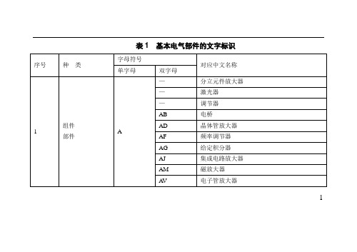
表1 基本电气部件的文字标识141213表2 电气电路中的常用辅助文字符号141516171819202122表3 图形符号表3-1 常用电子元器件的图形符号232425表3-2 常用低压电气部件的图形符号262728表3-3 常用高压电气部件的图形符号29表3-4 常用功能部件的图形符号30表3-5 常用照明灯具和特殊灯具图形符号3132表3-6 常用建筑用开关的图形符号3334表3-7 常用插座的图形符号35表3-8 建筑用开关和常见设备的图形符号36在敷设导线时,室内导线间最小距离要符合表4中的要求,绝缘导线至建筑物间的最小距离要符合表5中的要求。
表4 室内绝缘导线间最小距离37表5 绝缘导线至建筑物间的最小距离38使用明线进行敷设时也应符合设计规范,具体要求可参见表6。
表6 明线敷设的距离要求注:括号内数值为室外敷设要求室内导线与线缆选择完成后,需要选择穿导线使用的线管,保证导线的横截面积不超过线管的横截面积40%,保证线路的正常的散热。
39如选择截面积为2.5 mm2的导线,则应选择线管管径为16 mm的线管;如选择截面积为4mm2的导线,则应选择线管管径为19mm的线管。
这些都是按照需要穿入3根导线进行计算的,相关数据参考表7。
表7 横截面积、数量不同导线选择线管的管径4041在电工中常用的导线为铜芯线。
其横截面积不同的导线,其允许长期工作的电流见表8所列。
表8 导线横截面积不同温度下允许的最大载流量4243直流电动机型号的含义。
型号是指电动机的类型、系列及产品代号等,通常情况下采用的是大写英文字母和数字表示,如图1所示。
直流电动机常用字符代号对照表见表9所列。
图1 直流电动机型号的含义44表9 直流电动机常用字符代号对照45单相电动机型号的含义。
在单相交流电动机的名牌上标识有单相交流电动机的型号、额定转速、额定功率、额定电压、额定电流、额定频率、绝缘等级、防护等级、执行标准、出厂日期、编号和制造单位等。
北京彪骐佳讯

北京彪骐佳讯科技有限公司光纤收发器系列13.1 10/100M自适应光纤收发器产品描述10/100M自适应光纤收发器通过10BASE-T或100BASE-TX到100BASE-FX之间的光电转换,可以将传统的10M以太网或100M快速以太网通过快速以太网光纤链路扩展到110Km的范围。
产品图片产品特点●支持全双工和半双工网络通信,并带有自动协商能力●支持VLAN超长数据包的传输,可以与支持IEEE802.1Q协议的交换机产品匹配使用●支持LINK LOSS链路远程预告警功能●REMOTE PAUSE功能保证数据包传送的完整性●自适应10Mbps、100Mbps和10M/100Mbps环境,便于网络的升级●采用高性能的交换芯片和大容量的片内缓存,具有流量控制、差错检测等●功能,实现真正的无阻塞传输交换性能,保证数据传输的更高的安全性与稳定性●良好的散热性保证长时间的稳定工作●稳定可靠的开关电源,保证产品长时间不间断的工作●内置AC220V、DC-48V和外置5V供电,满足不同用户的需要技术参数产品应用订货信息选项1:光纤接口: SC-单/多模、ST-单/多模、FC-单/多模 选项2:结构形式: 内置电源、外置电源、收发模块13.2 单纤双向光纤收发器产品描述单纤双向光纤收发器通过单芯光纤的传输实现扩展基于双绞线的以太网目的,完成10BASE-T 或100BASE-TX 到100BASE-FX 之间的光电转换。
产品图片产品特点● 单纤光纤的传输极大的降低网络组建成本● 单模传输环境,可以将网络扩展至120km 的范围● 性能优异的光电器件保证了产品工作的稳定性和安全性 ● 内置AC220V 、DC-48V 和外置5V 供电,满足不同用户的需要技术参数产品应用:选项1:光纤接口:SC-单/多模、ST-单/多模、FC-单/多模选项2:结构形式:内置电源、外置电源、收发模块13.3 光纤收发器机架产品描述光纤收发器机架是一款用于机房内集中供电、集中管理的经济型光纤收发系统。
VS1003中文说明

VS1003-MP3/WMA 音频解码器VS1003 DataSheet 翻译版VS1003 特性:●能解码MPEG 1 和MPEG2 音频层III(CBR+VBR+ABR);WMA 4.0/4.1/7/8/9 5-384kbps 所有流文件;WAV(PCM+IMAAD-PCM);产生MIDI/SP-MIDI 文件。
●对话筒输入或线路输入的音频信号进行IMAADPCM编码●支持MP3 和WAV 流●高低音控制●单时钟操作12..13MHz●内部PLL锁相环时钟倍频器●低功耗●内含高性能片上立体声数模转换器,两声道间无相位差●内含能驱动30 欧负载的耳机驱动器●模拟,数字,I/O 单独供电●为用户代码和数据准备的5.5KB片上RAM●串行的控制,数据接口●可被用作微处理器的从机●特殊应用的SPI Flash引导●供调试用途的UART接口●新功能可以通过软件和4 GPIO 添加VS1003概述:●VS1003 是一个单片MP3/WMA/MIDI音频解码器和ADPCM编码器。
它包含一个高性能,自主产权的低功耗DSP 处理器核VS_DSP4,工作数据存储器,为用户应用提供5KB 的指令RAM 和0.5KB 的数据RAM。
串行的控制和数据接口,4 个常规用途的I/O 口,一个UART,也有一个高品质可变采样率的ADC和立体声DAC,还有一个耳机放大器和地线缓冲器。
●VS1003 通过一个串行接口来接收输入的比特流,它可以作为一个系统的从机。
输入的比特流被解码,然后通过一个数字音量控制器到达一个18 位过采样多位ε-ΔDAC。
通过串行总线控制解码器。
除了基本的解码,在用户RAM 中它还可以做其他特殊应用,例如DSP 音效处理。
PDF created with pdfFactory Pro trial version 4.1参数容许最大范围参数符号最小最大单位模拟正电源AVDD -0.3 3.6 V数字正电源CVDD -0.3 2.7 VI/O 正电源IOVDD -0.3 3.6 V所有数字口输出电流±50 mA所有数字口输入电压-0.3 IOVDD+0.31 V操作温度-40 +85 ℃存储温度-60 +150 ℃1 不能超过3.64.2建议操作环境参数符号最小值典型值最大值单位环境温度-25 +70 ℃模拟和数字地1 AGND DGND 0.0 V模拟正电源AVDD 2.6 2.8 3.6 V数字正电源CVDD 2.4 2.5 2.7 VI/O 正电源IOVDD CVDD-0.6V 2.8 3.6 V输入时钟频率2 XTAL1 12 12.288 13 MHz内部时钟频率CLKI 12 36.864 50.04 MHz内部时钟倍频数3 1.0x 3.0x 4.0x主机时钟占空比40 50 60 %1 必须相互连接并尽量靠近VS1003 以避免锁存上拉2 最大的采样率XTAL1/256,决定了能以正确的速度播放的音频采样率。
VSKDS409资料
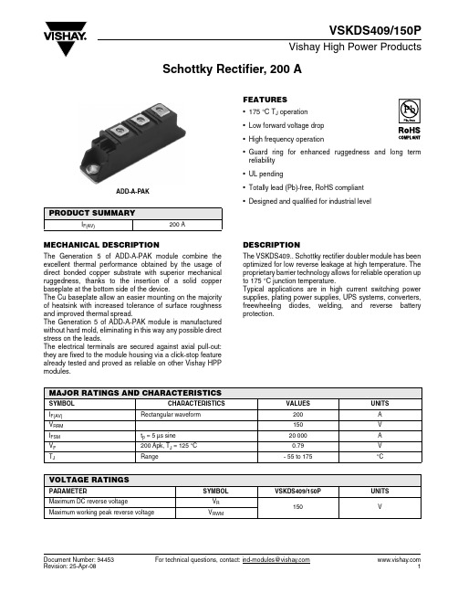
Document Number: 94453For technical questions, contact: ind-modules@Schottky Rectifier, 200 AVSKDS409/150PVishay High Power ProductsMECHANICAL DESCRIPTIONThe Generation 5 of ADD-A-PAK module combine the excellent thermal performance obtained by the usage of direct bonded copper substrate with superior mechanical ruggedness, thanks to the insertion of a solid copper baseplate at the bottom side of the device.The Cu baseplate allow an easier mounting on the majority of heatsink with increased tolerance of surface roughness and improved thermal spread.The Generation 5 of ADD-A-PAK module is manufactured without hard mold, eliminating in this way any possible direct stress on the leads.The electrical terminals are secured against axial pull-out:they are fixed to the module housing via a click-stop feature already tested and proved as reliable on other Vishay HPP modules.FEATURES•175 °C T J operation •Low forward voltage drop •High frequency operation•Guard ring for enhanced ruggedness and long term reliability •UL pending•Totally lead (Pb)-free, RoHS compliant •Designed and qualified for industrial levelDESCRIPTIONThe VSKDS409.. Schottky rectifier doubler module has been optimized for low reverse leakage at high temperature. The proprietary barrier technology allows for reliable operation up to 175 °C junction temperature.Typical applications are in high current switching power supplies, plating power supplies, UPS systems, converters,freewheeling diodes, welding, and reverse battery protection.PRODUCT SUMMARYI F(AV)200 AADD-A-PAKMAJOR RATINGS AND CHARACTERISTICSSYMBOL CHARACTERISTICS VALUESUNITS I F(AV)Rectangular waveform200A V RRM 150V I FSM t p = 5 µs sine 20 000A V F 200 Apk, T J = 125 °C 0.79V T JRange- 55 to 175°CVOLTAGE RATINGSPARAMETER SYMBOL VSKDS409/150PUNITS Maximum DC reverse voltageV R 150VMaximum working peak reverse voltageV RWM元器件交易网For technical questions, contact: ind-modules@Document Number: 94453VSKDS409/150PVishay High Power Products Schottky Rectifier, 200 ANote(1)Pulse width < 300 µs, duty cycle < 2 %ABSOLUTE MAXIMUM RATINGSPARAMETER SYMBOL TEST CONDITIONSVALUES UNITSMaximum average forward current I F(AV)50 % duty cycle at T C = 94 °C, rectangular waveform 200AMaximum peak one cycle non-repetitive surge current I FSM 5 µs sine or 3 µs rect. pulse Following any rated loadcondition and with rated V RRM applied20 00010 ms sine or 6 ms rect. pulse2300Non-repetitive avalanche energy E AS T J = 25 °C, I AS = 5.5 Amps, L = 1 mH15mJ Repetitive avalanche currentI ARCurrent decaying linearly to zero in 1 µsFrequency limited by T J maximum V A = 1.5 x V R typical1A ELECTRICAL SPECIFICATIONSPARAMETER SYMBOLTEST CONDITIONSVALUES UNITSMaximum forward voltage dropV FM (1)200 AT J = 25 °C 0.98V 400 A 1.23200 A T J = 125 °C 0.79400 A1.03Maximum reverse leakage current I RM (1)T J = 25 °C V R = Rated V R6mA T J = 125 °C85Maximum junction capacitance C T V R = 5 V DC (test signal range 100 kHz to 1 MHz) 25 °C 6000pF Typical series inductance L S From top of terminal hole to mounting plane 5.0nH Maximum voltage rate of change dV/dt Rated V R10 000V/µs RMS insulation voltageV INS50 Hz, circuit to base, all terminals shorted (1 s)3500V THERMAL - MECHANICAL SPECIFICATIONSPARAMETER SYMBOL TEST CONDITIONSVALUES UNITS Maximum junction and storagetemperature rangeT J , T Stg- 55 to 175°CMaximum thermal resistance, junction to case per leg R thJC DC operation 0.36°C/WMaximum thermal resistance, case to heatsink R thCSMounting surface, smooth and greased0.1Approximate weight 110g 4oz.Mounting torque ± 10 %to heatsink5Nmbusbar4Case styleJEDECTO-240AA元器件交易网Document Number: 94453For technical questions, contact: ind-modules@VSKDS409/150PSchottky Rectifier, 200 AVishay High Power ProductsFig. 1 - Maximum Forward Voltage Drop CharacteristicsFig. 2 - Typical Values of Reverse Current vs.Reverse Voltage Fig. 3 - Typical Junction Capacitance vs. Reverse VoltageFig. 4 - Maximum Thermal Impedance Z thJC Characteristics元器件交易网 For technical questions, contact: ind-modules@Document Number: 94453VSKDS409/150PVishay High Power Products Schottky Rectifier, 200 AFig. 5 - Maximum Allowable Case Temperature vs.Average Forward CurrentFig. 6 - Forward Power Loss CharacteristicsFig. 7 - Maximum Non-Repetitive Surge CurrentFig. 8 - Unclamped Inductive Test CircuitNote(1)Formula used: T C = T J - (Pd + Pd REV ) x R thJC ;Pd = Forward power loss = I F(AV) x V FM at (I F(AV)/D) (see fig. 6);Pd REV = Inverse power loss = V R1 x I R (1 - D); I R at V R1 = 80 % rated V R元器件交易网元器件交易网Schottky Rectifier, 200 A Vishay High Power Products ORDERING INFORMATION TABLECIRCUIT CONFIGURATIONLINKS TO RELATED DOCUMENTSDimensions /doc?95174Document Number: 94453For technical questions, contact: ind-modules@ Disclaimer Legal Disclaimer NoticeVishayAll product specifications and data are subject to change without notice.Vishay Intertechnology, Inc., its affiliates, agents, and employees, and all persons acting on its or their behalf (collectively, “Vishay”), disclaim any and all liability for any errors, inaccuracies or incompleteness contained herein or in any other disclosure relating to any product.Vishay disclaims any and all liability arising out of the use or application of any product described herein or of any information provided herein to the maximum extent permitted by law. The product specifications do not expand or otherwise modify Vishay’s terms and conditions of purchase, including but not limited to the warranty expressed therein, which apply to these products.No license, express or implied, by estoppel or otherwise, to any intellectual property rights is granted by this document or by any conduct of Vishay.The products shown herein are not designed for use in medical, life-saving, or life-sustaining applications unless otherwise expressly indicated. Customers using or selling Vishay products not expressly indicated for use in such applications do so entirely at their own risk and agree to fully indemnify Vishay for any damages arising or resulting from such use or sale. Please contact authorized Vishay personnel to obtain written terms and conditions regarding products designed for such applications.Product names and markings noted herein may be trademarks of their respective owners.元器件交易网Document Number: 。
卫生型称重模块 Novego

安装手册卫生型称重模块Novego®原版安装手册的翻译9499 053 26109版本 1.15.005/10/2022 Minebea Intec GmbH, Meiendorfer Str. 205 A, 22145 德国汉堡电话:+49.40.67960.303传真:+49.40.67960.383前言必须遵守!本文档中的任何信息如有更改,恕不另行通知,除非法律规定,并不代表Minebea Intec做出的任何承诺。
只能由经过培训和合格的人员操作/安装本产品。
在与本产品有关的信函中,必须引用与产品有关的类型、名称、版本号/序列号以及所有许可证号。
注意本文档部分受到版权保护。
未经购买或版权所有者(Minebea Intec)的书面许可,不得擅自修改或复制。
使用本产品即表示您接受上述规定的要求。
卫生型称重模块Novego®目录目录1介绍 (4)1.1阅读手册 (4)1.2这是使用说明的介绍 (4)1.3这是列表的介绍 (4)1.4这是菜单项和软键的介绍 (4)1.5这是安全指令的介绍 (4)1.6热线 (5)2安全指令 (6)2.1一般注意事项 (6)2.2预期用途 (6)2.3初步检查 (6)2.4在启动运行之前 (6)3安装建议 (7)3.1称重模块的位置 (7)4规格 (8)4.1与称重模块一起提供的设备 (8)4.2一般信息 (9)4.3用于防爆区域的称重传感器的可能标记 (10)4.4带摆锤底座 PR 6061/02S 的称重模块尺寸 (11)4.5带摆锤底座 PR 6061/03S 的称重模块尺寸 (12)4.6带摆锤底座 PR 6061/04S 的称重模块尺寸 (13)4.7带高度调节器 PR 6061/01S 的接装板尺寸 (14)4.8订购信息 (15)4.8.1称重传感器的订购信息 (15)4.8.2选配附件的订购信息 (15)4.8.3配件的订购信息 (15)4.9称重传感器的技术数据 (15)4.10运输锁和 PR 6061/06S 的技术数据 (17)5安装 (18)5.1在安装之前 (18)5.1.1准备基座 (18)5.1.2准备地面 (19)5.1.3准备容器底脚 (22)5.2拧紧扭矩 (23)Minebea Intec ZH-1卫生型称重模块Novego®目录5.3组件 (23)5.3.1安全指令 (23)5.3.2安装称重模块 (25)6连接 (37)6.1一般信息 (37)6.2称重传感器 (38)6.3电缆连接 (38)7准备校准 (40)7.1一般注意事项 (40)7.2智能校准 (40)7.3机械高度调整 (40)8故障排除 (41)8.1一般注意事项 (41)8.2目视检查 (41)8.3计量控制 (41)8.3.1检查称重传感器的零输出信号 (41)8.3.2检查称重传感器的应变仪电桥 (42)8.3.3检查称重传感器的绝缘阻抗 (42)8.3.4检查连接电缆的绝缘阻抗 (42)9保养/维修/清洁 (43)9.1护理和维护 (43)9.1.1维护 (43)9.1.2更换称重传感器 (43)9.2维修 (47)9.3清洁 (47)10废弃处置 (48)11选配附件 (49)11.1用于Novego®框架安装的 PR 6061/02S 摆锤底座 (49)11.2用于Novego®地面安装的 PR 6061/03S 摆锤底座 (50)11.3用于Novego®地面安装的 PR 6061/04S 摆锤底座,带倾斜校正 (51)12备件 (52)13配件 (53)13.1连接电缆 (53)13.2电缆接线盒 (53)13.3Connexx 模块 (54)ZH-2Minebea Intec卫生型称重模块Novego®目录13.3.1规格 (54)13.3.2连接 Connexx 模块 (55)13.3.3附挂选件 (56)13.3.4Connexx 模块的连接部件 (62)13.4用于 Novego®的 PR 6061/00S 接装板 (63)13.5用于 Novego®带高度调节器的 PR 6061/01S 接装板 (64)13.6用于 Novego®的 PR 6061/05S 金属板套装 (65)13.7Novego® 的PR 6061 /06S 运输和安装套件 (66)13.8PR 6061 / 07S,Novego® 固定轴承 (67)14证书/安全指示/控制图 (68)14.1BVS 16 ATEX E 005 (69)14.2IECEx BVS 16.0005 (73)14.3TÜV 03 ATEX 2301X (77)14.4IECEx TUN 17.0025X (83)14.5MIN16ATEX001X (87)14.6FM17CA0138 (89)14.7FM17US0276 (92)14.84012 101 5688 (95)14.9MEU18004 (96)14.10RU Д-DE.A301.B.05345 (102)14.11RU С-DE.МЮ62.В.05836 (103)14.12DE.C.28.001.A No. 70234 (106)14.13DE-15-PC-PTB009 (112)14.14R60/2000-NL1-17.41 (118)14.15TC11066 (120)14.1617-094 (123)14.1710032 (125)Minebea Intec ZH-3卫生型称重模块Novego® 1 介绍1介绍1.1阅读手册-在使用产品之前,请仔细阅读本手册。
- 1、下载文档前请自行甄别文档内容的完整性,平台不提供额外的编辑、内容补充、找答案等附加服务。
- 2、"仅部分预览"的文档,不可在线预览部分如存在完整性等问题,可反馈申请退款(可完整预览的文档不适用该条件!)。
- 3、如文档侵犯您的权益,请联系客服反馈,我们会尽快为您处理(人工客服工作时间:9:00-18:30)。
12 26 0.5
20050 SW 112th Ave. Tualatin, Oregon 97062 phone 503.612.2300 fax 503.612.2382
元器件交易网
rev. page date 2 of 3
01/2008
PART NUMBER: VSBU-150 series
-0.04% 16
mS mS
PROTECTION CIRCUIT
parameter output over current over voltage conditions/description min 110 112 nom max 150 132 units % %
GENERAL
parameter operating temp. storage temp. operating humid. storage humid. isolation voltage (HI-POT) RoHS safety conditions/description min 0 -40 5% 5% 50 4242 2121 nom max 70 85 95% 95% units ºC ºC RH RH number VSBU-150-9 VSBU-150-12 VSBU-150-15 VSBU-150-18 VSBU-150-24 VSBU-150-30 VSBU-150-36 VSBU-150-48
output voltage 9 V dc 12 V dc 15 V dc 18 V dc 24 V dc 30 V dc 36 V dc 48 V dc
元器件交易网
rev. page page date date 1 of 3
01/2008
PART NUMBER: VSBU-150 series
DESCRIPTION: single output switching power supply
features
• • • • wide input voltage range: 90~264 V ac, 47~63 Hz internal EMI filter single output input connector mates with Molex housing 09-50-3051 and Molex 2478 series crimp terminal • output connector mates with Molex housing 09-50-3061 (or 09-50-3081) and Molex 2478 series crimp terminal • output voltage available from 9 to 48 V dc • input surge current and over load protection • over voltage protection (crowbar design) • size: 3 x 5 x 1.09 inches • class I insulation • 2 year warranty
DESCRIPTION: single output switching power supply
OUTPUT
parameter ripple and noise line regulation load regulation temperature drift rise time hold-up time conditions/description min nom 0.5% 0.5% 3% max +1% +1% +5% +0.04% 4 units
non-condensing non-condensing 500 V dc test voltage primary to secondary primary to ground yes approved to UL/cUL, TUV-Baurart, CE, CISPR-22 class B, FCC part 15 class B, CB
output current 16 A 12.5 A 10 A 8.33 A 6.25 A 5A 4.17 A 3.13 A
total regulation ±5% ±5% ±5% ±4% ±3% ±2% ±2% ±2%
max output power 144 W 150 W 150 W 150 W 150 W 150 W 150 W 150 W
note:
1. to meet the standard of EN61204-3 class B, use the external noise filter between L and N (refer to manual)
20050 SW 112th Ave. Tualatin, Oregon 97062 phone 503.612.2300 fax 503.612.2382
元器件交易网
rev. page date 3 of 3
01/2008
PART NUMBER: VSBU-150 series
DESCRIPTION: single output switching power supply
MECHANICAL DRAWING
PIN 1 2 3 4 5 6 7 8 9 10 11 12 13*
INPUT
parameter input frequency input voltage input current inrush current leakage current conditions/description output power derated from 85-90 V ac AC input of 115 V ac AC input of 230 V ac measured at 115 V ac at full load, cold start measured at 230 V ac at full load, cold start measured at 240 V ac min 47 90 nom max 63 264 2.0 0.8 15 30 0.75 units Hz VAC A A A A mA
out out out out out out rtn rtn rtn rtn rtn rtn pfd
*13 is optional
20050 SW 112th Ave. Tualatin, Oregon 97062 phone 503.612.2300 fax 503.612.2382
