34063A_02
KA34063中文资料
V(OSC) TA = 25°C
Discharge to Charge Current Ratio
K
V7 = VCC, TA = 25°C
Current Limit Sense Voltage
VSENSE(C.L)
ICHG = IDISCHG TA = 25°C
OUTPUT SWITCH
Saturation Voltage 1 (Note1)
DISCLAIMER
FAIRCHILD SEMICONDUCTOR RESERVES THE RIGHT TO MAKE CHANGES WITHOUT FURTHER NOTICE TO ANY PRODUCTS HEREIN TO IMPROVE RELIABILITY, FUNCTION OR DESIGN. FAIRCHILD DOES NOT ASSUME ANY LIABILITY ARISING OUT OF THE APPLICATION OR USE OF ANY PRODUCT OR CIRCUIT DESCRIBED HEREIN; NEITHER DOES IT CONVEY ANY LICENSE UNDER ITS PATENT RIGHTS, NOR THE RIGHTS OF OTHERS.
2
元器件交易网 Typical Performance Characteristics
Temperature (°C) Figure 1. Temperature Drift (VTH)
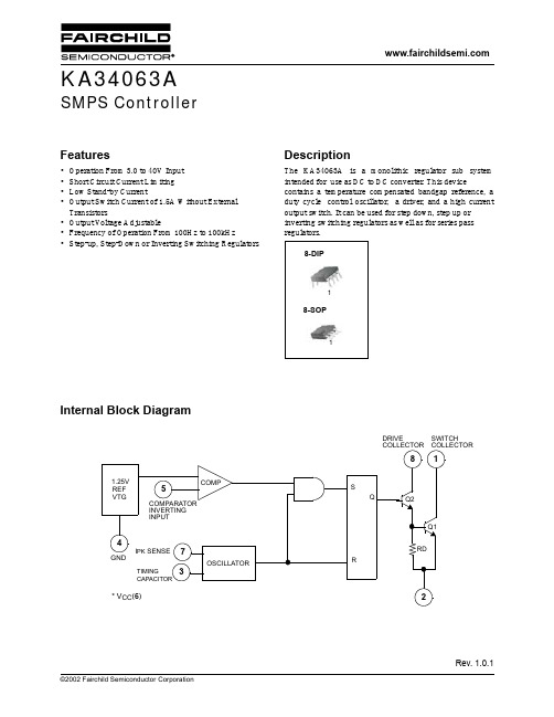
KA34063A
3
元器件交易网
KA34063A
Mechanical Dimensions
2. A critical component in any component of a life support device or system whose failure to perform can be reasonably expected to cause the failure of the life support device or system, or to affect its safety or effectiveness.
34063技术手册

MC34063ADC-DC CONVERTER CONTROL CIRCUITS®April 2000sOUTPUT SWITCH CURRENT IN EXCESS OF 1.5As 2%REFERENCE ACCURACYs LOW QUIESCENT CURRENT:2.5mA (TYP.)s OPERATING FROM 3V TO 40Vs FREQUENCY OPERATION TO 100KHz sACTIVE CURRENT LIMITINGDESCRIPTIONThe MC34063A series is a monolithic control circuit delivering the main functions for DC-DC voltage converting.The device contains an internal temperature compensated reference,comparator,duty cycle controlled oscillator with an active current limit circuit,driver and high current output switch.Output voltage is adjustable through two external resistors with a 2%reference accuracy.Employing a minimum number of external components the MC34063A devices series is designed for Step-Down,Step-Up and Voltage-Inverting applications.BLOCK DIAGRAMDIP-8SO-81/15ABSOLUTE MAXIMUM RATINGSSymbol ParameterValue Unit V CC Power Supply Voltage50V V ir Comparator Input Voltage Range -0.3to 40V V SWC Switch Collector Voltage40V V SWE Switch Emitter Voltage (VSWC =40V)40V V CE Switch Emitter to Collector Voltage 40V V d c Driver Collector Voltage 40V I dc Driver Collector Current 100mA I SW Switch Current1.5A P tot Power Dissipation at T amb =25o C (for Plastic Package )(for SOIC Package ) 1.250.625WT op Operating Ambient Temperature Range (for AC SERIES )(for AB SERIES )0to 70-40to 85o C o C T st gStorage Temperature Range-40to 150oCAbsolute Maximum Rating are those values beyond which damage to the device may occur.Functional operation under these condition is not implied.THERMAL DATASymbolParameterDIP-8SO-8UnitR thj-amb Thermal Resistance Junction-ambient (*)Max100160oC/W(*)This value depends from thermal design of PCB on which the device is mounted.ORDERING NUMBERSTypeDIP-8SO-8SO-8(tape &reel)MC34063AB MC34063ABN MC34063ABD MC34063ABD-TR MC34063ACMC34063ACNMC34063ACDMC34063ACD-TRCONNECTION DIAGRAM (top view)PIN CONNECTIONSPin No Symbol Name and Function 1SWC Switch Collector 2SWE Switch Emitter 3TC Timing Capacitor 4GND Ground5CII Comparator Inverting Input 6V CC Voltage Supply 7I pk I pk Sense8DRCVoltage Driver CollectorMC34063A2/15ELECTRICAL CHARACTERISTICS(Refer to the test circuits,V CC=5V,T a=T LOW to T HIGH,unless otherwise specified,see note2)OSCILLATORSymbol Parameter Test Conditions Min.Typ.Max.Unitf OSC Frequency V pin5=0V C T=1nF T a=25o C243342KHzI ch g Charge Currernt V CC=5to40V T a=25o C243342µAI dischg Discharge Current V CC=5to40V T a=25o C140200260µA I d is chg/I chg Discharge to ChargeCurrent RatioPin7=V CC T a=25o C 5.2 6.27.5V i pk(sense)Current Limit Sense Voltage I chg=I dischg T a=25o C250300350mV OUTPUT SWITCHSymbol Parameter Test Conditions Min.Typ.Max.Unit V CE(sat)Saturation Voltage,Darlington ConnectionI SW=1A Pins1,8connected1 1.3VV CE(sat)Saturation Voltage I SW=1A R pin8=82Ωto V CC,Forcedβ~200.450.7Vh F E DC Current Gain I SW=1A V CE=5V T a=25o C50120I C(off)Collector Off-State Current V CE=40V0.01100µA COMPARATORSymbol Parameter Test Conditions Min.Typ.Max.UnitV t h Threshold Voltage T a=25o CT a=T LOW to T HIGH 1.2251.211.25 1.2751.29VVReg li ne Threshold Voltage LineRegulationV CC=3to40V15mVI I B Input Bias Current V IN=0V-5-400nA TOTAL DEVICESymbol Parameter Test Conditions Min.Typ.Max.UnitI CC Supply Current V CC=5to40V C T=1nFPin7=V CC V pin5>V th Pin2=GNDRemaining pins open2.54mANOTES:1)Maximum package power dissipation limit must be observed.2)T LOW=0o C,T HIGH=70o C(AC series);T LOW=-40o C,T HIGH=85o C(AB series).3)If Darlington configuration is not used,care must be taken to avoid deep saturation of output switch.The resulting switch-off time may be adversely affected.In a Darlington configuration the following output driver condition is suggested:Forcedβ of output current switch=I COUTPUT/(I CDRIVER-1mA*)≥10*Current less due to a built in1KΩantileakage resistor.MC34063A3/15Common Emitter Configuration Output Switch Saturation Voltage vs Collector Current Power Collector Emitter Saturation Voltage (V CE(sat))vs Temperature Darlington Configuration Collector Emitter Saturation Voltage(V CE(sat))vs Temperature Current Limit Sense Voltage Voltage(V ipk)vs TemperatureEmitter Follower Configuration Output Saturation Voltage vs Emitter Current Output Switch ON-OFF Time vs Oscillator Timing CapacitorTYPICAL ELECTRICAL CHARACTERISTICS MC34063A4/15MC34063ATYPICAL ELECTRICAL CHARACTERISTICS(Continued)Reference Voltage vs Temperature Bias Current vs TemperatureSupply Current vs Temperature Supply Current vs Input Voltage5/15MC34063ATYPICAL APPLICATION CIRCUITStep-Up ConverterPrinted DemoboardSymbol PinVout1GND2GND3Vin4Test Condition(V OUT=28V)Test Conditions Value(Typ.)Unit Line Regulation V IN=8to16V,I O=175mA30mV Load Regulation V IN=12V,I O=75to175mA10mV Output Ripple V IN=12V,I O=175mA300mV Efficency V IN=12V,I O=175mA89%6/15MC34063A Step-Down ConverterPrinted DemoboardSymbol PinVout1GND2GND3Vin4Test Condition(V OUT=5V)Test Conditions Value(Typ.)Unit Line Regulation V IN=15to25V,I O=500mA5mV Load Regulation V IN=25V,I O=50to500mA30mV Output Ripple V IN=25V,I O=500mA100mV Efficency V IN=25V,I O=500mA80%I SC V IN=25V,R LOAD=0.1Ω 1.2A7/15MC34063AVoltage Inverting ConverterPrinted DemoboardSymbol PinVout1GND2GND3Vin4Test Condition(V OUT=-12V)Test Conditions Value(Typ.)Unit Line Regulation V IN=4.5to6V,I O=100mA15mV Load Regulation V IN=5V,I O=10to100mA20mV Output Ripple V IN=5V,I O=100mA230mV Efficency V IN=5V,I O=100mA58% I SC V IN=5V,R lLOAD=0.1Ω0.9A8/15CalculationParameter Step-Up(Discontinuos mode)Step-Down(Continuos mode)Voltage Inverting(Discontinuos mode)t on/t off V out+V F−V in(min)V i n(min)−V sa tV out+V FV i n(min)−V sat−V out|V out|+V FV in−V s at(t on+t off)max1/f min1/f min1/f mi nC T 4.5x10⁻⁵t on 4.5x10⁻⁵t on 4.5x10⁻⁵t o nI PK(switch)2I ou t(max)[(t o n/t off)+1]2I out(max)2I out(max)[(t on/t off)+1] R SC0.3/I PK(switc h)0.3/I PK(switc h)0.3/I PK(switch)C O≅I out t onV ri pple(p−p)I PK(s witc h)(t on+t off)8V ri pple(p−p)≅I out t o nV ripp le(p−p)L(min)V in(mi n)−V s atI PK(swit ch)t o n(max)V in(min)−V sa t−V o utI PK(swit ch)t on(max)V in(mi n)−V satI PK(s witch)t on(ma x)NOTES:V sat=Saturation voltage of the output switchV F=Foward voltage drop of the output rectifierTHE FOLLOWING POWER SUPPLY CHARACTERISTICS MUST BE CHOSEN:V in=Nominal input voltageV out=Desired output voltage,|V out|=1.25(1+R2/R1)I out=Desired output currentf min=Minimum desired output switching frequency at the selected values of Vin and IoV ripple=Desired peak to peak output ripple voltage.In practice,the calculaed capacitor value will and to be increased due to its equivalent series resistance and board layout.The ripple voltage should be kept to a low value since it will directly affect the line and load regulation. Step-up With External NPN SwitchMC34063A9/15MC34063AStep-down With External NPN Switch Step-down With External PNP Switch 10/15Voltage Inverting With External NPN SwitchVoltage Inverting With External PNP Saturated Switch11/15Dual Output VoltageHigher Output Power,Higher Input Voltage 12/15Plastic DIP-8MECHANICAL DATAmm inchDIM.MIN.TYP.MAX.MIN.TYP.MAX.A 3.30.130a10.70.028B 1.39 1.650.0550.065B10.91 1.040.0360.041b0.50.020b10.380.50.0150.020D9.80.386E8.80.346e 2.540.100e37.620.300e47.620.300F7.10.280I 4.80.189L 3.30.130Z0.44 1.60.0170.063P001F13/15SO-8MECHANICAL DATAmm inch DIM.MIN.TYP.MAX.MIN.TYP.MAX.A 1.750.068a10.10.250.0030.009 a2 1.650.064 a30.650.850.0250.033 b0.350.480.0130.018 b10.190.250.0070.010 C0.250.50.0100.019 c145(typ.)D 4.8 5.00.1880.196E 5.8 6.20.2280.244e 1.270.050e3 3.810.150F 3.8 4.00.140.157L0.4 1.270.0150.050 M0.60.023 S8(max.)0016023 14/15Information furnished is believed to be accurate and reliable.However,STMicroelectroni c s assumes no responsibility for the consequences of use of such information nor for any infringement of patents or other rights of third parties which may result from its use.No license is granted by implication or otherwise under any patent or patent rights of STMicroelectroni c s.Specification mentioned in this publication are subject to change without notice.This publication supersedes and replaces all informati o n previously supplied.STMicroelectronics products are not authorized for use as critical components in life support devices or systems withoutexpress written approval of STMicroelectronics.The ST logo is a registered trademark of STMicroelectronics©2000STMicroelectronics–Printed in Italy–All Rights ReservedSTMicroelectronics GROUP OF COMPANIESAustralia-Brazil-China-Finland-France-Germany-Hong Kong-India-Italy-Japan-Malaysia-Malta-MoroccoSingapore-Spain-Sweden-Switzerland-United Kingdom-U.S.A..15/15。
34063AP1
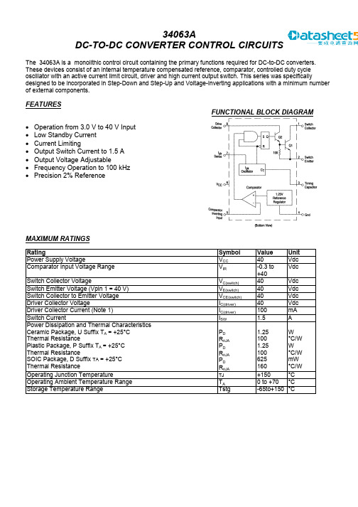
34063ADC-TO-DC CONVERTER CONTROL CIRCUITSThe 34063A is a monolithic control circuit containing the primary functions required for DC-to-DC converters.These devices consist of an internal temperature compensated reference, comparator, controlled duty cycleoscillator with an active current limit circuit, driver and high current output switch. This series was specificallydesigned to be incorporated in Step-Down and Step-Up and Voltage-Inverting applications with a minimum numberof external components.FEATURESFUNCTIONAL BLOCK DIAGRAM• Operation from 3.0 V to 40 V Input • Low Standby Current • Current Limiting • Output Switch Current to 1.5 A • Output Voltage Adjustable • Frequency Operation to 100 kHz • Precision 2% ReferenceMAXIMUM RATINGSRating Symbol Value Unit Power Supply Voltage V CC 40 VdcComparator Input Voltage Range V IR -0.3 to +40VdcSwitch Collector Voltage V C(switch) 40 VdcSwitch Emitter Voltage (Vpin 1 = 40 V) V E(switch) 40 VdcSwitch Collector to Emitter Voltage V CE(switch) 40 VdcDriver Collector Voltage I C(driver) 40 VdcDriver Collector Current (Note 1) I C(driver) 100 mASwitch Current I SW 1.5 APower Dissipation and Thermal Characteristics Ceramic Package, U Suffix T A = +25°C Thermal Resistance Plastic Package, P Suffix T A = +25°C Thermal Resistance SOIC Package, D Suffix TA = +25°C Thermal Resistance P D R θJAP D R θJA P D R θJA1.25 100 1.25 100 625 160W°C/W W °C/W mW °C/W Operating Junction Temperature TJ +150 °COperating Ambient Temperature Range T A 0 to +70 °CStorage Temperature Range Tstg -65to+150°CORDERING INFORMATIONDevice TemperatureRange Package 34063AD 0° to +70°CSO-8 34063AP1Plastic DIPELECTRICAL CHARACTERICISTICS (V CC = 5.0 V, T A = 0 to +70o C unless otherwise specified.)Characteristics Symbol Min Typ Max UnitOSCILLATORFrequency (V Pin 5 = 0 V, C T = 1.0 nF, T A = 25°C) f osc 24 33 42 kHzCharge Current (V CC = 5.0 V to 40 V, T A = 25°C) I chg 24 33 42 µADischarge Current (V CC = 5.0 V to 40 V, T A = 25°C) I dischg 140 200 260 µADischarge to Charge Current Ratio (Pin7 to Vcc, T A =25°C) I dischg /I chg 5.2 6.2 7.5 —Current Limit Sense Voltage (Ichg = Idischg, T A = 25°C) V lpk (sense) 250300 350 mV OUTPUT SWITCH (Note 3)Saturation Voltage, Darlington Connection (I SW = 1.0 A, Pins 1, 8 connected)V CE (sat) — 1.0 1.3 V Saturation Voltage (I SW = 1.0 A, R Pin 8 = 82 Ω to V CC . Forced β = 20) V CE (sat) — 0.45 0.7 VDC Current Gain (I SW = 1.0 A, V CE = 5.0 V, T A = 25°C) h FE 50 120 — —Collector Off-State Current (V CE = 40V) I C (off) — 0.01 100 µACOMPARATORThreshold Voltage (T A = 25°C) (T A = T LOW to T HIGH ) Vth 1.225 1.21 1.25 — 1.275 1.29V Threshold Voltage (T A = 25°C) ** Vth 1.2375 1.251.2625 VThreshold Voltage Line Regulation (V CC = 3.0 V to 40 V) V REG line 1.4 5.0 mVInput Bias Current (Vin=0V) I IB — -40 -400 nATOTAL DEVICESupply Current (V CC = 5 0 V to 40 V, C T = 1 0 nF, V pin7 = V CC . V Pin5 > Vth, Pin 2 = Gnd, Remaining pins open) I CC2.5 4.0 mANOTES:1. Maximum package power dissipation limits must be observed.2. Low duty cycle pulse techniques are used during test to maintain Junction temperature as close to ambienttemperature as possible3. If the output switch is driven into hard saturation (non Darlington configuration) at low switch currents (< 300 mA) andhigh driver currents (>30 mA), it may take up to 2.0 µs to come out of saturation This condition will shorten the off' timeat frequencies > 30 kHz, and is magnified at high temperatures This condition does not occur with a Darlington configuration,since the output switch cannot saturate If a non Darlington configuration is used, the following output drive condition isrecommendedForced β of output switch = I C , output/(Ic, driver -7.0 mA*) > 10*The 100 Ω. resistor in the emitter of the driver device requires about 7.0 mA before the output switch conducts**Possible version for shipmentPin connection。
主板芯片一览表电脑维修集成电路图
主板芯片一览表电脑维修集成电路图:1. IO系列:37b77x 37b80x 37c665ir 37c669fr 37c67x 37c68x 37c93xapm 37c93xfr 37c957fr 37m602 37m707 37m81x 37n869 37n958fr 37n972 37n972add 37n972add 02&12ap00001 02&12ap01001 627sf 697hf 8661CG_V2.0 8702&8712CG_v1.0 8705&8700CG_v2.08761ap99007 8761CG_v0.2 877atf 877tf 977e_ct 977tf it8712f_PG_cir_v01 it8712f_PG_ec_v02 it8712f_PG_scr_v02 w83601r602r w83601r602r-1 w83627hf W83697HF W83697SF w83977ATF W83L517D W83L518D smsc 02&12ap00001 02&12ap01001 627sf 697hf 8661CG_V2.0 8702&8712CG_v1.0 8705&8700CG_v2.0 8761ap99007 8761CG_v0.2 877atf 877tf 977e_ct 977tf it8712f_PG_cir_v01 it8712f_PG_ec_v02 it8712f_PG_scr_v02 w83601r602r w83601r602r-1 w83627hf W83697HF W83697SF w83977A TF W83L517D W83L518Dsmsc:37b77x 37b80x 37c665ir 37c669fr 37c67x 37c68x 37c93xapm 37c93xfr 37c957fr 37m602 37m707 37m81x 37n869 37n958fr 37n972 37n972add2. 接口定义:PCMCIA引脚定义:SO DIMM 144线内存条ATA 44 接口A TA 接口ESDI 接口IDE 接口Mitsumi CD-ROM 接口Panasonic CD-ROM 接口Sony CD-ROM 接口内置SCSI卡接口(差分信号方式) 内置SCSI卡接口(单端信号方式) 软驱接口DIMM DRAM 168线内存条SIMM 30线内存条SIMM 72线内存条SIMM ECC 72线内存条SO DIMM 72线内存条15针VGA 显示接口25针外置SCSI接口9针VGA 显示接口CGA 显示接口ECP 并行口定义EGA 显示接口PC 串行口定义PC 游戏杆接口PS 2 键盘接口定义PS 2 鼠标接口定义RS-232 define RS-422 serial port USB 总线定义VGA Vesa DDC显示接口并口单色MDA 显示接口键盘接口定义外置SCSI高密接口(差分信号方式) 外置SCSI高密接口(单端信号方式) 外置SCSI接口(差分信号方式) 外置SCSI接口(单端信号方式) 以太网100Base-T4 接口以太网10-100Base-T 接口游戏杆+MIDI 接口定asm back01 AGP总线定义EISA总线定义ISA 总线定义PCI总线定义PCI总线定义1 VESA总线定义3. 电源稳压IC:AN9805hip6018 CM8501 DS34063A-07(1) DS34063A-07 DS9131-00P(1) DS9131-00P DS9161A-19 DS9162-09 DS9163-15 DS9164-13 DS9165-08 DS9167A-12 DS9168A-04 DS9169-04 DS9170-00P DS9172-05P DS9173A-08 DS9174-00P DS9177-03P DS9178-00P DS9181-01P DS9182-03P DS9185-00P DS9202-02 DS9203-01P DS9204-00P DS9205-01P DS9224-04 DS9224C-01P DS9224E-01P DS9226B-01P DS9227A-02P DS9228-03 DS9231A-02 DS9237-01 DS9238-01P(1) DS9238-01P DS9261A-03P(1) DS9261A-03P DS9261B-03P(1) DS9261B-03P DS9262A-04P(1) DS9262A-04P DS9263-02P(1) DS9263-02P DS9266-01P(1) DS9266-01P DS9267-02P(1) DS9267-02P DS9268-00P(1) DS9268-00P DS9269-00P(1) DS9269-00P DS9541-05P DS9600-00P(1) DS9600-00P DS9602-00P(1) DS9602-00P DS9701-05(1) DS9701-05 DS9801-02P(1) DS9801-02P DS9802-00P(1) DS9802-00P DS9808-01P(1) DS9808-01P DS9809-02P(1) DS9809-02P International Rectifier IRU3007 IRU3011 IRU3013 IRU3018 IRU3021M IRU3027 IRU3034 IRU3037 IRU3038 IRU3046 IRU3047 IRU3048 IRU3055 L1084 L1084s L1084s3 L1084t L1085-3.3-010705 L1085d L1085s L1085s3 L1085t L1085t-3.3-010705 L1087 L1087c L1089C-33 L1117L L1581 L2030ATB L431-A L431-B L432-A L432-B L78L09 L78L15 L78L18 L78LXX N1155 N2576 N2576-3.3 N2576-5 RC5051 Richtek Semtech - Charge Pumps Semtech - ProgrammableSynchronous DC-DC Controller SS-AIC2951 us3004 US3033 HIP6524 HIP6004 HIP6004A HIP6004B HIP6004D HIP6005HIP6005A HIP6005BHIP6006 HIP6007 HIP6008 HIP6012 HIP6013 HIP6014 HIP6015 HIP6016 HIP6017 hip6018 HIP6018B HIP6019 HIP6019B HIP6020 HIP6021 HIP6301International Rectifier.files :fp021005LM系列:22521iru3013 2639 2639 LM2636 LM2637 LM2638RT系列:RT34063 RT9131 RT9161 RT9162 RT9163 rt9164 RT9165 RT9167 RT9168 RT9169 RT9169 RT9171 RT9172 RT9173A RT9177 RT9220 RT9221 RT9222 RT9223 RT9223A RT9224 RT9225 RT9226A RT9227A RT9228 RT9229 RT9230 RT9231 RT9232 RT9233 RT9235 rt9238-01P RT9261 RT9262 RT9541 RT9568 RT9641 RT9642 RT9701SC系列:SC1101 SC1102 SC1103 SC1104 SC1109 SC110X SC1110 SC1116 SC113X SC1150 SC1151 SC1152 sc1153(1) sc1153 sc1153.pdf.!!! sc1155 SC1156 SC1157 SC1158 SC1159 SC1162-3 sc1164 SC1164-5 SC1166 SC1167 SC1175 SC117X SC1182-3 SC1182B SC1185 SC1186 SC1187 SC1188 SC1189 SC1403 SC1406A SC1406G SC1408 SC1409 SC1417B SC1462 SC1462A SC1470 sc1471page1 sc1474page1 sc1476page1 SC1477 SC1480 SC1485 SC1486 SC1517-5 SC2420 SC2422A SC2449 SC2450 SC2453 SC2595 SC2610 SC2612 SC2643VX SC2672 SC4508 SC4601 SC4602 SC4605 SC600 SC603Semtech - Charge Pumps.files:BLACK SEMTECH SPACER sub_background sub_blackgrade_leftcorn sub_blackgrade_middle sub_blackgrade_rightcorn4:时钟发生器:ICS%209248-199 ics9179-12 ics9248-90 ICS9248-96 ICS9250-08 ics9250-09 W83176R_705 W83176R_716 W83193R-0204 W83194AR_We W83194AR-96 W83194BR_250 W83194BR_39B W83194BR_63S W83194BR_640 W83194BR_730 W83194BR_740 W83194BR_B W83194BR_KX W83194BR_P4X W83194BR-323 W83194R_39A W83194R_58A W83194R_67B W83194R_81 W83194R-17A W83194R-630A W83195BR_25 W83195R-08 W83196R。
TS34063A中文资料
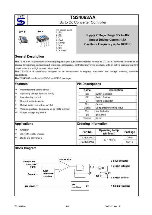
TS34063AADc to Dc Converter ControllerSupply Voltage Range 3 V to 40V Output Driving Current 1.5A Oscillator Frequency up to 100KHzGeneral DescriptionThe TS34063A is a monolithic switching regulator and subsystem intended for use as DC to DC converter. It contains an internal temperature compensated reference, comparator, controlled duty cycle oscillator with an active peak current limit circuit, drive and a high current output switch.The TS34063A is specifically designed to be incorporated in step-up, step-down and voltage inverting converter applications.The TS34063A is offered in SOP-8 and DIP-8 package.FeaturesPower forward control circuit Operating voltage form 3V to 40V Low standby current Current limit adjustable Output switch current up to 1.5AVariable oscillator frequency up to 100KHz (max)Output voltage adjustablePin DescriptionsName DescriptionSC Switch CollectorSE Switch Emitter CT Timing Capacitor Gnd Ground Comp. Comparator Inverting Input Vcc Vcc Collector Ipk Ipk Sense Vdriver DriverApplicationsChargerxD-ROM, xDSL productDC to DC converter sOrdering InformationPart No.Operating Temp.(Ambient)PackageTS34063ACD DIP-8 TS34063ACS-20 ~ +85 oCSOP-8Block DiagramPin assignment:1. SC 2. SE 3. CT 4. Gnd 5. Comp. 6. Vcc 7. Ipk 8. VdriverAbsolute Maximum RatingSupply Voltage V CC 40 V Comparator Input Voltage Range V FB- 0.3 ~ 40 VSwitch Collector Output Voltage V C(SW) 40 V Switch Emitter Voltage V E(SW) 40 V Switch Collector to Emitter Voltage V CE(SW) 40 V Driver Collector Voltage Vc(driver) 40 VDriver Collector Current (note 1) Ic(driver) 100 mAOutput Switching Current I SW 1.5 APower Dissipation DIP-8SOP-8 Pd1.00.5WOperating Junction Temperature Range T J-0 ~ +125 o C Storage Temperature Range T STG-65 ~ +150 o C Note: Maximum package power dissipation limits must be observedElectrical Characteristics (VCC=5V, Ta =25 o C; unless otherwise specified.)Parameter SymbolTestConditionsMinTypMaxUnit Oscillator (OSC)Frequency F OSC C T = 1nF, Vpin5= 0V 24 33 42 KHz Charge Current I CHARGE V CC = 5V ~ 40V -- 30 -- uA Discharge Current I DISCHARGE V CC = 5V ~ 40V -- 200 -- uADischarge to Charge current ratio I DISCHARGE/ I CHARGEPin7 to Vcc -- 6.5 -- --Current Limit Sense Voltage V IPK(SENSE)I DISCHARGE = I CHARGE 250--350mV Output switch (note1)Saturation Voltage V CE(SAT)I SW= 1A, pin1,8 connected) -- 1.0 1.3 VSaturation Voltage V CE(SAT)I SW= 1A, Id=50mA -- 0.45 0.7 VDC current gain H FE I SW = 1A, Vce= 0.5V -- 75 -- --Collector off-state current I C(OFF)Vce= 40V -- 0.01 100 uA ComparatorThreshold Voltae V REF 1.225 1.25 1.275 VLine regulation RegLine V CC = 3V ~ 40V -- -- 6 mVTotal deviceSupply Current I CC V CC = 5V ~ 40V, C T = 1nF,pin7=Vcc, pin5>Vth,pin2=Gnd, remaining pinsopen-- 1.6 3 mANote: 1. Low duty cycle pulse techniques are used during test to maintain junction temperature as close to ambient temperature as possible2. If the output switch is driven into hard saturation (non-Darlington configuration) at low switch currents (<=300mA)and high driver currents (>=30mA), it may take up to 2uS for it to come out of saturation. This condition will shorten the off time at frequencies >= 30KHz, and is magnified at high temperature. This condition does not occur with a Darlington configuration, since the output switch cannot saturate. If a non-Darlington configuration is used, the following output drive condition is recommended:Forced Bata of output switch: Ic output / (Ic driver – 7mA*) >= 10* The 100ohm resistor in the emitter of the driver divide requires about 7mA before the output switch conducts.Circuit DescriptionTypical Application CircuitFigure 7. Step Up ConverterResults Test ConditionsLINE REGULATION Vin= 8V~16V, Io= 175mA 30mV +/- 0.05%Load Regulation Vin= 12V, Io= 75mA to 175mA 10mV +/- 0.017%Output Ripple Vin=12V, Io= 175mA 400mVppEfficiency Vin=12V, Io= 175mA 87.7%Output Ripple with Optional Filter Vin=12V, Io= 175mA 40mVppTypical Application Circuit (continues)Figure 9. Step Down ConverterResults Test ConditionsLine Regulation Vin= 15V~25V, Io= 500mA 12mV +/- 0.12%Load Regulation Vin= 25V, Io= 50mA to 500mA 3mV +/- 0.03%Output Ripple Vin= 25V, Io= 500mA 120mVppShort Circuit Current Vin= 25V, RL= 0.1ohm 1.1AEfficiency Vin= 25V, Io= 500mA 83.7%Output Ripple with Optional Filter Vin= 25V, Io= 500mA 40mVppTypical Application Circuit (continues)Figure 11. Voltage Inverting ConverterResults Test ConditionsLine Regulation Vin= 4.5V~6.0V, Io= 100mA 3mV +/- 0.012%Load Regulation Vin= 5V, Io= 10mA to 100mA 22mV +/- 0.09%Output Ripple Vin= 5V, Io= 100mA 500mVppShort Circuit Current Vin= 5V, RL= 0.1ohm 900mAEfficiency Vin= 5V, Io= 100mA 62.2%Output Ripple with Optional Filter Vin= 5V, Io= 100mA 70mVpp。
34063中文资料

联系电话:0755-29790719
传真:07558-29790840
深圳市联拓辉电子有限公司
引脚分布原理图
网站:
联系电话:0755-29790719
传真:07558-29790840
深圳市联拓辉电子有限公司
极限参数
电参数
网站:
设计规范表
电路原理
内部框图中所表示的电路解释如下: 振荡器通过恒流源对外接在 CT 管脚(3 脚)上的定时电容不断地充电和放电,以产生振荡波形。充电和放 电电流都是恒定的,所以振荡频率仅取决于外接定时电容的容量。与门的 C 输入端在振荡器对外充电时为高 电平,D 输入端在比较器的输入电平低于阈值电平时为高电平。当 C 和 D 输入端都变成高电平时,触发器被 置为高电平,输出开关管导通。反之,当振荡器在放电期间,C 输入端为低电平,触发器被复位,使得输出 开关管处于关闭状态。 限制 SI 检测端(5 脚)通过检测连接在 V+和 5 脚之间电阻上的压降来完成功能。 当检测到电阻上的电压降 接近超过 300mV 时,电流限制电路开始工作。这时通过 CT 管脚(3 脚)对定时电容进行快速充电,以减少充电 时间和输出开关管的导通时间,结果是使得输出开关管的关闭时间延长 。
�
34063 的封装形式为塑封双列 8 引线。
主要特性
� � � � � � � 能在 3.0-40V 的输入电压下工作 短路电流限制 低静态电流 输出开关电流可达 1.5A(无外接三极管) 输出电压可调 工作振荡频率从 100HZ 至 100KHZ 可构成升压 降压或反向电源变换器
网站:
深圳市联拓辉电子有限公司
34063 DC/DC 变换器控制电路-----34063
概述与特点
贴片三极管A

MAX6326_R22-T Max MAX6327_R22-T Max MAX6328_R22-T Max MAX809LXR MAX809MXR MAX809TXR MAX809SXR MAX809RXR MAX803ZXR MAX810LXR Max Max Max Max Max Max Max
类型 I I N C C AQ AQ AQ K A A A A A
封装 SCD80 USM SOT323 SOT23 SOT323
参数及代换型号 35V 100mA pin 100V 50mA sw npn RF 8 GHz HP2800 schottky HP2800 schottky modamp MAR 3 Similar modamp MAR 6 Similar modamp MAR 7 Similar HP2800 schottky
A 字贴片参数代号识别代码表示 表示符 号 A A A A0 A0 A03 A06 A07 A1 A1 A1 A1 A1p A1t A1t A1s A1s A1s A1X A2 A2 A2 A2s A2 A2 A2 A22 A2X 生产 厂 Sie Roh Mot HP HP MC MC MC HP Phi Phi Phi Phi Phi Phi Sie Sie Sie Mot HP HP Phi Sie Mot Sie Mot Phi Mot A A A A D D C C A CQ DO C A SOT23 SOT323 SOT23 SOT23 SOT23 SOT143 SOT363 SOD27 SOT23
A6 A6p A6 A6A A6B A6C A6D A6E A6F A6G A6H A6J A6K A6L A6X A7s A7s A7s A7s A7 A7 A7 A8 A8 A8 A8 A8A A8B A8C A8D A8E A8F
施耐德低压断路器说明书 - Compact NSX, Easypact CVS, Easypact

Low Voltage Circuit Breaker 1 to 1600ACompact NSX 100 /160/250Compact NSX 400/630Compact NS 800 to 1600Easypact CVS 160/250Easypact CVS 400/630Easypact EZC 100Acti 9Low Voltage Circuit Breakers 1 to 1600 APageActi 92681226344256Easypact EZC 100Easypact CVS 160 to 630Compact NSX 100 to 630Compact NS 800 to 1600Accessories OverviewTripping Curves Dimensions and Mounting Secection TableSelection table -Acti 9Acti9Vigi iC60漏電保護模組應用技術資料Vigi iC60漏電模組內含殘餘電流電磁機械動作方式,無須輔助電源。
額定電流:動作時間重量(g)接線小於25A :電纜最大可接至25mm 22P 斷路器3P 斷路器組合示意圖2P Vigi 模組3P Vigi 模組小於63A :電纜最大可接至35mm 225A 145 63A165 25A 184 63A 210符合IEC61008/61009跳脫時間(Triping time)與漏電電流(I Δn)關係如下:Vigi iC60 漏電模組內含濾波裝置,可有效防止由於瞬間電壓變化。
(照明或設備產生線路電壓波動…)和突波電流所引起的誤動作。
Vigi iC60漏電模組適用63A 及63A 以下的iC60 系列斷路器Vigi iC60漏電模組(額定電流)選定可向下相容:Ex. Vigi iC60 ≦40A 可直接搭配 Acti-9 iC60N MCB 40A 或40A 以下。
MC34063或MC33063 接成标准DC-DC电路元件参数的自动计算

MC34063或MC33063 接成标准DC-DC电路元件参数的自动计算上一篇/ 下一篇 2010-10-01 08:02:26查看( 8 ) / 评论( 0 ) / 评分( 0 / 0 ) MC34063或IRM03A接成标准的DC—DC1:极性反转。
2:升压。
3:降压。
三种典型电路时,外围元件参数的自动计算使用方法:只要在左中部框中输入你想要的参数,然后点击“进行计算并且刷新电路图”按钮,它就可以自动给所有相关的外围元件参数和相对应的标准电路图纸,使设计DC—DC电路实现智能化高效化。
关于警告:如果您输入的参数超过了34063的极限,它会自动弹出警告窗口提醒您更改它们。
特殊输入:要设计极性反转电路请在输入或输出电压数字的前面加上负号,比如-5V。
MC34063或MC33063是一种用于DC-DC电源变换的集成电路,应用比较广泛,通用廉价易购。
极性反转效率最高65%,升压效率最高90%,降压效率最高80%,变换效率和工作频率滤波电容等成正比。
另外,输出功率达不到要求的时候,比如>250~300MA时,可以通过外接扩功率管的方法扩大电流,双极型或MOS型扩流管均可,计算公式和其他参数及其含义详见最下部详细介绍即可。
输入电压V输出电压V输出电流mA输出电压波纹系mV(pp)数工作频率kHz外围元件标称含义和它们取值的计算公式:Vout(输出电压)=1.25V(1+R1/R2)Ct(定时电容):决定内部工作频率。
Ct=0.000 004*Ton(工作频率)Ipk=2*Iomax*T/toffRsc(限流电阻):决定输出电流。
Rsc=0.33/IpkLmin(电感):Lmin=(Vimin-Vces)*Ton/ IpkCo(滤波电容):决定输出电压波纹系数,Co=Io*ton/Vp-p(波纹系数)固定值参数:Vces=1.0V ton/toff=(Vo+Vf-Vimin)/(Vimin-Vces)Vimin:输入电压不稳定时的最小值Vf=1.2V 快速开关二极管正向压降其他手册参数:在实际应用中要注意:1:快速开关二极管可以选用IN4148,在要求高效率的场合必须使用IN5819!2:34063能承受的电压,即输入输出电压绝对值之和不能超过40V,否则不能安全稳定的工作。
MC34063 MC34063A(MC33063)芯片器件简介
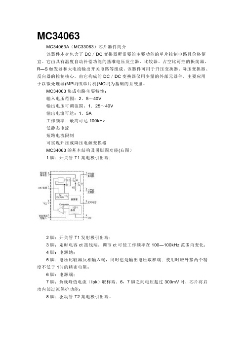
MC34063MC34063A(MC33063)芯片器件简介该器件本身包含了DC/DC变换器所需要的主要功能的单片控制电路且价格便宜。
它由具有温度自动补偿功能的基准电压发生器、比较器、占空比可控的振荡器,R—S触发器和大电流输出开关电路等组成。
该器件可用于升压变换器、降压变换器、反向器的控制核心,由它构成的DC/DC变换器仅用少量的外部元器件。
主要应用于以微处理器(MPU)或单片机(MCU)为基础的系统里。
MC34063集成电路主要特性:输入电压范围:2、5~40V输出电压可调范围:1.25~40V输出电流可达:1.5A工作频率:最高可达100kHz低静态电流短路电流限制可实现升压或降压电源变换器MC34063的基本结构及引脚图功能(右图)1脚:开关管T1集电极引出端;2脚:开关管T1发射极引出端;3脚:定时电容ct接线端;调节ct可使工作频率在100—100kHz范围内变化;4脚:电源地;5脚:电压比较器反相输入端,同时也是输出电压取样端;使用时应外接两个精度不低于1%的精密电阻;6脚:电源端;7脚:负载峰值电流(Ipk)取样端;6,7脚之间电压超过300mV时,芯片将启动内部过流保护功能;8脚:驱动管T2集电极引出端。
左图是电压逆变器右图是降压转换器主要参数:项目条件参数单位Power Supply Voltage 电源电压VCC 40 Vdc Comparator Input Voltage Range 比较器输入电压范围VIR 0.3-+40 Vdc Switch Collector Voltage 集电极电压开关VC(switch) 40 VdcSwitch Emitter Voltage (VPin 1 = 40 V) 发射极电压开关VE(switch) 40 VdcSwitch Collector to Emitter Voltage 开关电压集电极到发射极VCE(switch)40 VdcDriver Collector Voltage 驱动集电极电压VC(driver) 40 Vdc Driver Collector Current (Note 1) 驱动集电极电流IC(driver) 100 mA Switch Current 开关电流ISW 1.5 A Operating Junction Temperature工作结温TJ +150 ℃Operating Ambient Temperature Range操作环境温度TA MC340630-70℃范围 AMC34063的工作原理MC34063组成的降压电路MC34063组成的降压电路原理如图7。
国外的34063A芯片计算器

The maximum ambient temperayellow table. The value of maxitemperature Tj = 150°C.(DO NOT CHANGE)2) Input Conduction Loss Parameters from Free-wheeling Diode Datasheets- Found in Electrical Characteristics of Datasheet,Darlington Configuration3) Set D IL/IL(avg)For Maximum Output Current it is suggested that ΔIL should be chosen to be less than 10% of the average inductor curre This will help prevent Ipk (sw) from reaching the current limit threshold set by RSC. If the design goal isinductance value, let ΔIL = 2*IL(avg). This will proportionally reduce output current capability.D IL / IL(avg)D IL4) Input target frequency5) The spreadsheet calculates key parameters for the remaining component selec∆i L* increasing inductance decreas 6) Efficiency / Power Lossximum ambient temperature is related to one-layer PCB with parameters mentioned in the aboveyellow table. The value of maximum ambient temperature is calculated for maximum allowable junction temperature Tj = 150°C.Input Voltage: 4V < Vin < 40VOutput Voltage: 1.25V < Vout < (Vin*Dmax)4%of Datasheet,0% of the average inductor current, IL(avg).oal is to use a minimumponent selectionerter this equals Ioutthis equals Iout + Iripple/2* increasing inductance decreases ripple current ata sheet or measurement).data sheet. Leave blank if not available.Rev 0.1 7/22/09。
电源芯片34063api(免费)
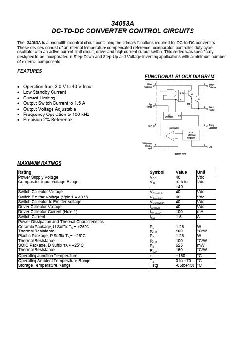
34063ADC-TO-DC CONVERTER CONTROL CIRCUITSThe 34063A is a monolithic control circuit containing the primary functions required for DC-to-DC converters.These devices consist of an internal temperature compensated reference, comparator, controlled duty cycleoscillator with an active current limit circuit, driver and high current output switch. This series was specificallydesigned to be incorporated in Step-Down and Step-Up and Voltage-Inverting applications with a minimum numberof external components.FEATURESFUNCTIONAL BLOCK DIAGRAM• Operation from 3.0 V to 40 V Input • Low Standby Current • Current Limiting • Output Switch Current to 1.5 A • Output Voltage Adjustable • Frequency Operation to 100 kHz • Precision 2% ReferenceMAXIMUM RATINGS Rating Symbol Value Unit Power Supply Voltage V CC 40 VdcComparator Input Voltage Range V IR -0.3 to +40VdcSwitch Collector Voltage V C(switch) 40 VdcSwitch Emitter Voltage (Vpin 1 = 40 V) V E(switch) 40 VdcSwitch Collector to Emitter Voltage V CE(switch) 40 VdcDriver Collector Voltage I C(driver) 40 VdcDriver Collector Current (Note 1) I C(driver) 100 mASwitch Current I SW 1.5 APower Dissipation and Thermal Characteristics Ceramic Package, U Suffix T A = +25°C Thermal Resistance Plastic Package, P Suffix T A = +25°C Thermal Resistance SOIC Package, D Suffix TA = +25°C Thermal Resistance P D R θJAP D R θJA P D R θJA1.25 100 1.25 100 625 160W°C/W W °C/W mW °C/W Operating Junction Temperature TJ +150 °COperating Ambient Temperature Range T A 0 to +70 °CStorage Temperature Range Tstg -65to+150°CORDERING INFORMATIONDevice Temperature RangePackage 34063AD 0° to +70°CSO-8 34063AP1Plastic DIPELECTRICAL CHARACTERICISTICS (V CC = 5.0 V, T A = 0 to +70o C unless otherwise specified.)Characteristics Symbol Min Typ Max UnitOSCILLATORFrequency (V Pin 5 = 0 V, C T = 1.0 nF, T A = 25°C) f osc 24 33 42 kHzCharge Current (V CC = 5.0 V to 40 V, T A = 25°C) I chg 24 33 42 µADischarge Current (V CC = 5.0 V to 40 V, T A = 25°C) I dischg 140 200 260 µADischarge to Charge Current Ratio (Pin7 to Vcc, T A =25°C) I dischg /I chg 5.2 6.2 7.5 —Current Limit Sense Voltage (Ichg = Idischg, T A = 25°C) V lpk (sense) 250300 350 mV OUTPUT SWITCH (Note 3)Saturation Voltage, Darlington Connection (I SW = 1.0 A, Pins 1, 8 connected)V CE (sat) — 1.0 1.3 V Saturation Voltage (I SW = 1.0 A, R Pin 8 = 82 Ω to V CC . Forced β = 20) V CE (sat) — 0.45 0.7 VDC Current Gain (I SW = 1.0 A, V CE = 5.0 V, T A = 25°C) h FE 50 120 — —Collector Off-State Current (V CE = 40V) I C (off) — 0.01 100 µACOMPARATORThreshold Voltage (T A = 25°C) (T A = T LOW to T HIGH ) Vth 1.225 1.21 1.25 — 1.275 1.29V Threshold Voltage (T A = 25°C) ** Vth 1.2375 1.251.2625 VThreshold Voltage Line Regulation (V CC = 3.0 V to 40 V) V REG line 1.4 5.0 mVInput Bias Current (Vin=0V) I IB — -40 -400 nATOTAL DEVICESupply Current (V CC = 5 0 V to 40 V, C T = 1 0 nF, V pin7 = V CC . V Pin5 > Vth, Pin 2 = Gnd, Remaining pins open) I CC2.5 4.0 mANOTES:1. Maximum package power dissipation limits must be observed.2. Low duty cycle pulse techniques are used during test to maintain Junction temperature as close to ambienttemperature as possible3. If the output switch is driven into hard saturation (non Darlington configuration) at low switch currents (< 300 mA) andhigh driver currents (>30 mA), it may take up to 2.0 µs to come out of saturation This condition will shorten the off' timeat frequencies > 30 kHz, and is magnified at high temperatures This condition does not occur with a Darlington configuration,since the output switch cannot saturate If a non Darlington configuration is used, the following output drive condition isrecommendedForced β of output switch = I C , output/(Ic, driver -7.0 mA*) > 10*The 100 Ω. resistor in the emitter of the driver device requires about 7.0 mA before the output switch conducts**Possible version for shipmentPin connection。
34063 中文资料

1/fMIN
4 10-5 tON(MAX) 2 IOUT(MAX)
4 10-5 tON(MAX)
2* IO UT (MAX ) *
tO N − tOFF tOFF
2* IO UT ( MAX ) *
tO N+tOFF tOFF
i-y
* tON( MAX )
RSC
L(MIN)
VIPK(SENSE)/IPK(SENSE)
34063
Rsc Vin 14V 0.22 8 7 6 100 H 180 1 2 5 R1 48k 150 F D1(SBD) V0=30V Vin 25V
双极型线性集成电路
Rsc 0.33 8 7 6 4 100 F 470pF 3 1 2 5 D1(SBD) R1 1.2K 220 H R2 3.6k 470 F V0=5.0V 100 H
D1(SBD)
90 H
/bbs 电子器件采购平台: IC资料查询网站: 电子工程技术论坛:
.ta w w w
4 3 100 F 1500pF
图1 升压变换器
图2 降压变换
器
Rsc
L
D1(SBD)
Voutபைடு நூலகம்Vin C0
ELECTRONICS CO., LTD------LTD-------
/bbs 电子器件采购平台: IC资料查询网站: 电子工程技术论坛:
34063
工作原理
双极型线性集成电路
由于内置有大电流的电源开关 34063能够控制的开关电流达到1.5A 内部线路包含有参考电压源 振荡器 转换器 逻 辑控制线路和开关晶体管 参考电压源是温度补偿的带隙基准源 振荡器的振荡频率由3脚的外接定时电容决定.开关晶体管由比较器的反向输入端和
电源IC代换
发一些电源IC的代换资料DAP8A\DAP7A\LD7575\203D6\203X6\200D6可以直接代换,203d6是16v工作电压,而7575是30v ,代用要改启动电阻,可以用1200AP40直接代用OB2268,OB2269,DAP02,SG6841,SG5841DAP02\SG5841\2G684 1可以直接代换1200AP40\1200AP60\1203P60\1203AP10可以直接代换DM0465\CM0565\DM0565代换{要改电路}T O P246Y\T O P247Y可以直接代换。
大家来整理一个液晶电源的电源管理芯片集吧格式如下好了液晶品牌与型号电源管理芯片型号与封装可代换型号BENQ 71G+ 1200AP40 直插 1200AP10 1200AP60AOC 712SI EA1532A贴片三星型号忘记 DM0565R优派型号忘记 TOP245YNLG型号忘记 FAN7601飞利浦170s6 dap02alsz 贴片LG型号忘记 FAN7601 可以用LAF0001代飞利浦170s6 dap02alsz=sg6841美格WB9D7575PS清华同方XP911WD7575PS联想LXM -WL19AH LXM-WL19BH D7575PS(早期有的用:NCP1203D6) 联想LXM-17CH:1203D6方正17寸:1203D6与LD7575PS方正19寸:LD7575PSBenQ: FP94VW FP73G FP71G+S FP71G+G FP71GX等都是用:1200AP40 LG 22(南京同创):LAF001与STR W6252 。
LG 19寸:LAF001联想L193(福建-捷联代工):NCP1203D6PHILIPS 170S5FAN7601)PHILIPS 15寸(老产品):(FAN7601)LG型号忘记 FAN7601 可以用LAF0001代其他我知道的常用型号有SG6841DZ 贴片很多机器上用到SG5841SZ 贴片用SG6841DZ可以代用,DAP8A与203D6可代用还有LD7575可用203D6代用,只是1脚的对地电阻不同,LD7575是100K,203D6是24.1K,LP7552可用SG6841代用203D6 NCP1203D60R2 NCP1203D60R2G和DAP8A直接代换DAP02ALSZ与SG6841S可以互换1200AP40和1200AP60直接代换5S0765和DP104、DP704直接代换DP804和DP904直接代换2S0680和2S0880直接代换TEA1507和TEA1533直接代换LD7535兼容SG6848 (6849) / SG5701 / SG5848 /LD7535 (7550) / OB2262 (2263) / OB2278 (2279)RS2051LD7575和NCP1203、NCP1200 OB2268 SG5841 LD7552 OB2269 OB2268 RS2042CR6860兼容ACT30,CR6853兼容OB2263,CR6201兼容THX201,TFC718;CR6202兼容THX202,TFC719;CR6203兼容THX203,TFC718S。
MC34063芯片设计的计算公式及应用讲解
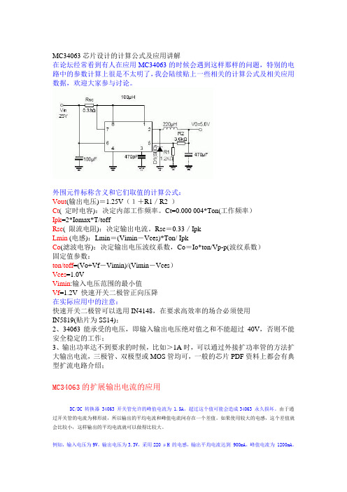
MC34063芯片设计的计算公式及应用讲解在论坛经常看到有人在应用MC34063的时候会遇到这样那样的问题,特别的电路中的参数计算上很是不太明了,我会陆续贴上一些相关的计算公式及相关应用数据,欢迎大家参与讨论。
外围元件标称含义和它们取值的计算公式:Vout(输出电压)=1.25V(1+R1/R2 )Ct( 定时电容):决定内部工作频率。
Ct=0.000 004*Ton(工作频率)Ipk=2*Iomax*T/toffRsc( 限流电阻):决定输出电流。
Rsc=0.33/IpkLmin (电感):Lmin=(Vimin-Vces)*Ton/ IpkCo(滤波电容):决定输出电压波纹系数,Co=Io*ton/Vp-p(波纹系数)固定值参数:ton/toff=(Vo+Vf-Vimin)/(Vimin-Vces)Vces=1.0VVimin:输入电压范围的最小值Vf=1.2V 快速开关二极管正向压降在实际应用中的注意:快速开关二极管可以选用IN4148,在要求高效率的场合必须使用IN5819(贴片为SS14);2、34063能承受的电压,即输入输出电压绝对值之和不能超过40V,否则不能安全稳定的工作;3、输出功率达不到要求的时候,比如>1A时,可以通过外接扩功率管的方法扩大输出电流,三极管、双极型或MOS管均可,一般的芯片PDF资料上都会有典型扩流电路介绍;MC34063的扩展输出电流的应用DC/DC 转换器 34063 开关管允许的峰值电流为 1.5A,超过这个值可能会造成34063 永久损坏。
由于通过开关管的电流为梯形波,所以输出的平均电流和峰值电流间存在一个差值。
如果使用较大的电感,这个差值就会比较小,这样输出的平均电流就可以做得比较大。
例如,输入电压为9V,输出电压为3.3V,采用220 μH 的电感,输出平均电流达到 900mA,峰值电流为 1200mA。
单纯依赖34063 内部的开关管实现比900mA 更高的输出电流不是不可以做到,但可靠性会受影响。
AZ34063A中文资料
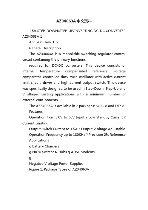
AZ34063A中文资料1.5A STEP-DOWN/STEP-UP/INVERTING DC-DC CONVERTER AZ34063A 1Apr. 2005 Rev. 1. 2General DescriptionThe AZ34063A is a monolithic switching regulator control circuit containing the primary functionsrequired for DC-DC converters. This device consists of internal temperature compensated reference, voltage comparator, controlled duty cycle oscillator with active current limit circuit, driver and high current output switch. This device was specifically designed to be used in Step-Down, Step-Up and V oltage-Inverting applications with a minimum number of external com-ponents.The AZ34063A is available in 2 packages: SOIC-8 and DIP-8.FeaturesOperation from 3.0V to 36V Input ? Low Standby Current ? Current LimitingOutput Switch Current to 1.5A ? Output V oltage Adjustable Operation Frequency up to 180KHz ? Precision 2% Reference Applicationsg Battery Chargersg NICs/ Switches/ Hubs g ADSL ModemsgNegative V oltage Power SuppliesFigure 1. Package Types of AZ34063A1.5A STEP-DOWN/STEP-UP/INVERTING DC-DC CONVERTER AZ34063A 2Apr. 2005 Rev. 1. 2Figure 2. Pin Configuration of AZ34063ATop ViewP/M Package (DIP-8/SOIC-8)Pin ConfigurationFunctional Block DiagramFigure 3. Functional Block Diagram of AZ34063ASwitch Timing Switch GNDPK Sense CCCollector CapacitorEmitter DriverCollector Switch CollectorSwitchEmitterTiming CapacitorGNDDriver CollectorI PK SenseV CCComparator Inverting Input1.5A STEP-DOWN/STEP-UP/INVERTING DC-DC CONVERTER AZ34063A 3Apr. 2005 Rev. 1. 2Package Temperature Range Part NumberMarking IDPacking TypeTin Lead Lead Free Tin LeadLead Free SOIC-8-40 to 85o C AZ34063AM AZ34063AM-E134063AM 34063AM-E1Tube AZ34063AMTRAZ34063AMTR-E134063AM34063AM-E1Tape & ReelDIP-8-40 to 85o CAZ34063APAZ34063AP-E1AZ34063APAZ34063AP-E1TubeBCD Semiconductor's Pb-free products, as designated with "E1" suffix in the part number, are RoHS compliant.Circuit Type Package M: SOIC-8E1: Lead Free Blank: Tin Lead AZ34063A -TR: Tape and Reel Blank: TubeP: DIP-8Pin NumberPin Name Function1Switch Collector Internal switch transistor collector 2Switch Emitter Internal switch transistor emitter3Timing CapacitorTiming Capacitor to control the switching frequency 4GNDGround pin for all internal circuits 5Comparator Inverting InputInverting input pin for internal comparator 6V CC V oltage supply7I PK Sense Peak Current Sense Input by monitoring the voltage drop across an external I sense resistor to limit the peak current through the switch 8Driver CollectorV oltage driver collectorPin DescriptionOrdering Information1.5A STEP-DOWN/STEP-UP/INVERTING DC-DC CONVERTER AZ34063A 4Apr. 2005 Rev. 1. 2Note 1: Stresses greater than those listed under "Absolute Maximum Ratings" may cause permanent damage to the device.These are stress ratings only, and functional operation of the device at these or any other conditions beyond those indicated under "Recommended Operating Conditions" is not implied. Exposure to "Absolute Maximum Ratings" for extended periods may affect device reliability.Note 2: Maximum package power dissipation limits must be observed.Recommended Operating ConditionsParameter Symbol Min Max Unit Supply V oltage V CC 336V Ambient TemperatureT A-4085oCParameterSymbol Value Unit Power Supply V oltageV CC 40V Comparator Input V oltage Range V IR -0.3 to 40V Switch Collector V oltageV C (switch)40V Switch Emitter V oltage (Vpin1=40V)V E (switch)40V Switch Collector to Emitter V oltage V CE (switch)40V Driver Collector V oltage V C (driver)40V Driver Collector Current (Note 2)I C (driver)100mA Switch CurrentI SW1.5APower Dissipation and Thermal Characteristics Plastic Package,Power Dissipation (T A = 25 ?) Thermal Resistance SOIC Package,Power Dissipation (T A = 25 ?) Thermal Resistance P D R T J P D R T JA 1.25100 625 160W ?/W mW ?/W Operating Junction Temperature T J 150?Storage Temperature Range T STG -65 to 150?ESD (Human body model)2000VAbsolute Maximum Ratings (Note 1)1.5A STEP-DOWN/STEP-UP/INVERTING DC-DC CONVERTER AZ34063A 5Apr. 2005 Rev. 1. 2(V CC = 5.0 V , T A = -40 to 85o C, unless otherwise specified.) Note 3: Low duty cycle pulse technique are used during test to maintain junction temperature as close to ambient temperature as possible.Note 4: If the output switch is driven into hard saturation (non-Darlington configuration) at low switch currents (d 300mA) and high driver currents (t 30mA), it may take up to 2.0us for it to come out of saturation. This condition will shorten the off time at frequencies 30KHz, and is magnified at high temperatures. This condition does not occur with a Darlington configuration,since the output switch cannot saturate. If a non-Darlington configuration is used, the following output drive condition is rec-ommended:Parameter Symbol ConditionsMin Typ Max Unit OSCILLATOR Frequency f OSC VPin 5 = 0 V , CT = 1.0 nF T A = 25o C303845KHz Charge Current I CHG V CC = 5.0 V to 36 V , T A = 25o C 303845P A Discharge CurrentI DISCHGV CC = 5.0 V to 36 V , T A = 25o C180240290P ADischarge to Charge Current RatioI DISCHG /I CHG Pin 7 to V CC , T A= 25o C5.26.57.5Current Limit Sense V oltage V IPK (sense) ICHG = I DISCHG , T A = 25o C250300350mV OUTPUT SWITCH (Note 3)Saturation V oltage,Dalington Connection V CE (sat)I SW = 1.0 A,Pins 1, 8 connected1.0 1.3V Saturation V oltage (Note 4.) V CE (sat)I SW = 1.0 A, RPin 8 = 82 : to V CC , Forced E = 200.450.7VDC Current Gainh FE I SW = 1.0 A, V CE = 5.0 V , T A = 25o C 5075Collector Off-State Current I C (off)V CE = 36 V0.01100P ACOMPARATOR Threshold V oltageV TH T A = 25o C 1.225 1.250 1.275V T A = -40 to 85o C 1.211.29Threshold V oltage Line Regulation R EGLINEV CC = 3.0 V to 36 V 1.45mV Input Bias Current I IBV IN = 0 V-20-400nA TOTAL DEVICE Supply CurrentI CCV CC = 5.0 V to 36 V , CT = 1.0 nF,Pin 7 = V CC , VPin 5 > V TH ,4mA Electrical Characteristics1.5A STEP-DOWN/STEP-UP/INVERTING DC-DC CONVERTER AZ34063A 6Apr. 2005 Rev. 1. 2Figure 4. Output Switch On-Off Time vs. Figure 5. Timing Capacitor WaveformTypical Performance CharacteristicsOscillator Timing CapacitorI C outputt 10Forced E of output switch:* The 100: resistor in the emitter of the driver device requires about 7.0 mA before the output switch conducts.I C driver - 7.0mA*Time. 10P s/DIVV o s c . O s c i l l a t o r V o l t a g e (V )200m V /D I VPin 1,5,8 = open CT=1.0nF T A =25o CV CC =5.0V Pin 7=V CC Pin 2=GNDFigure 6. Oscillator Frequency vs.Timing CapacitorFigure 7. Standard Supply Current vs. Supply VoltageElectrical Characteristics (Continued)1.5A STEP-DOWN/STEP-UP/INVERTING DC-DC CONVERTER AZ34063A Typical Performance Characteristics (Continued)Figure 8. Emitter Follower Configuration Output Figure 9. Common Emitter Configuration Output Switch Saturation Voltage vs. Emitter current Saturation Voltage vs. Collector CurrentFigure 10. Current Limit Sense Voltage vs. TemperatureApr. 2005 Rev. 1. 271.5A STEP-DOWN/STEP-UP/INVERTING DC-DC CONVERTER AZ34063A Typical ApplicationsFigure 10. Step-Up Converter (Note 5)Note 5: This is a typical step-up converter configuration. In the steady state, if the resistor divider voltage at pin5 is greater than the voltage in the non-inverting input, which is 1.25V determined by the internal reference, the output of the comparator will go low. At the next swithching period, the output switch will not conduct and the output voltage will eventually drop below its nominal voltage until the divider voltage at pin 5 is lower than 1.25V.Then the output of the comparator will go high, the output switch will be allowed to conduct. Since Vpin5 = V OUT * R2/(R1+R2) = 1.25(V), the output voltage can be decided by V OUT = 1.25 * (R1+R2)/R2 (V).Apr. 2005 Rev. 1. 281.5A STEP-DOWN/STEP-UP/INVERTING DC-DC CONVERTER AZ34063A Typical Applications (Continued)Figure 11. Step-Down converter (Note 6)Note 6: This is a typical step-down converter configuration. The working process in the steady state is similar to step-up converter, Vpin5 = V OUT * R2/(R1+R2) = 1.25 (V), the output voltage can be decided by V OUT = 1.25 * (R1+R2)/R2 (V).Apr. 2005 Rev. 1. 291.5A STEP-DOWN/STEP-UP/INVERTING DC-DC CONVERTER AZ34063A Typical Applications (Continued)Figure 12. Voltage Inverting Converter (Note 7)Note 7: This is a typical inverting converter configuration. The working process in the steady state is similar to step-upconverter, the difference in this situation is that the voltage at the non-inverting pin of the comparator is equal to 1.25V+V OUT, then Vpin5 = V OUT * R2/(R1+R2) = 1.25V+V OUT, so the output voltage can be decided by V OUT = -1.25 * (R1+R2)/R1 (V).Apr. 2005 Rev. 1. 2101.5A STEP-DOWN/STEP-UP/INVERTING DC-DC CONVERTER AZ34063A Mechanical DimensionsSOIC-8Unit: mm(inch)Apr. 2005 Rev. 1. 2111.5A STEP-DOWN/STEP-UP/INVERTING DC-DC CONVERTER AZ34063A Mechanical Dimensions (continued)DIP-8Unit: mm(inch)Apr. 2005 Rev. 1. 212/doc/23f0a013a8114431b80dd800.ht mlBCD Semiconductor Corporation3170 De La Cruz Blvd, Suite # 105 Santa Clara, CA 95054-2411, U.S.A Tel: +1-408-988 6388, Fax: +1-408-988 6386 Shanghai SIM-BCD Semiconductor Manufacturing Co., Ltd.800 Yi Shan Road, Shanghai 200233, PRC Tel: +86-21-6485-1491, Fax: +86-21-5450-0008 Advanced Analog Circuits (Shanghai) Corporation8F, B Zone, 900 Yi Shan Road, Shanghai 200233, PRC Tel: +86-21-6495 9539, Fax: +86-21-6485 9673 BCD Semiconductor(Taiwan) Company LimitedRoom 2210, 22nd Fl, 333, Keelung Road, Sec. 1, TaiPei (110), Taiwan Tel: +886-2-2758 6828, Fax: +886-2-2758 6892 IMPORTANT NOTICEBCD Semiconductor Manufacturing Limited reserves the right to make changes without further notice to any pro-ducts or specifications herein. BCD Semiconductor Manufacturing Limited does not assume any responsibility for use of any its products for any particular purpose, nor does BCD Semiconductor Manufacturing Limited assume any liability arising out of the application or use of any its products or circuits. BCD Semiconductor Manufacturing Limi-ted does not convey any license under its patent rights or other rights nor the rights of others.。
34063中文
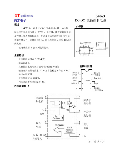
管脚排列图
1 2 34063B 3 4 8 7 6 5 驱动管 集电极 Ipk 传感 电源 比较器 反向端输入
定时电容
地
内部功能框 3
驱动管 集电极 开关管 集电极 开关管 发射极
IPK
传感
输入 电压 比 较 器 反 向端输入
定时 电容 地
第1 页 共 5页
GT-goldentec
高泰电子
引出端功能符号
参 电源电压
数 名 称
符 号 Vcc VIR Vc(switch)
V (switch)
E
单位 V V V V V V mA A 1.25 °C °C
比较器输入电压范围 输出管集电极电压 输出管发射极电压(VPIN1=40V) 输出管集电极与发射极间的电压 驱动管集电极电压 驱动管集电极电流 输出电流 功耗 工作环境温度 贮存温度
结 3.0mV=±0.012% 0.022V=+0.09% 500mVpp 910mA 64.5% 70mVpp
果
输出纹波 电路限制电流 效率 输出纹波
第4 页 共
5 页
GT-goldentec
高泰电子
特性曲线
ton-of f (u S) 振荡 器电 压 V osc路
DC-DC 变换控制电路
应用图例
34063B 作反转式 DC-DC 变换器
如图 3 所示, 当加接 LC 滤波器后,能进一步减小电压纹波及噪声,特性见下表 参 线性调整率
负载调整率
数
测 试 条 件 VIN=4.5~6.0V,Io=100mA VIN=5.0V,Io=10~100mA VIN=5.0V,Io=100mA VIN=5.0V,RL=0.1Ω VIN=5.0V,Io=100mA VIN=5.0V,Io=100mA
电源芯片34063api(免费)

34063ADC-TO-DC CONVERTER CONTROL CIRCUITSThe 34063A is a monolithic control circuit containing the primary functions required for DC-to-DC converters.These devices consist of an internal temperature compensated reference, comparator, controlled duty cycleoscillator with an active current limit circuit, driver and high current output switch. This series was specificallydesigned to be incorporated in Step-Down and Step-Up and Voltage-Inverting applications with a minimum numberof external components.FEATURESFUNCTIONAL BLOCK DIAGRAM• Operation from 3.0 V to 40 V Input • Low Standby Current • Current Limiting • Output Switch Current to 1.5 A • Output Voltage Adjustable • Frequency Operation to 100 kHz • Precision 2% ReferenceMAXIMUM RATINGS Rating Symbol Value Unit Power Supply Voltage V CC 40 VdcComparator Input Voltage Range V IR -0.3 to +40VdcSwitch Collector Voltage V C(switch) 40 VdcSwitch Emitter Voltage (Vpin 1 = 40 V) V E(switch) 40 VdcSwitch Collector to Emitter Voltage V CE(switch) 40 VdcDriver Collector Voltage I C(driver) 40 VdcDriver Collector Current (Note 1) I C(driver) 100 mASwitch Current I SW 1.5 APower Dissipation and Thermal Characteristics Ceramic Package, U Suffix T A = +25°C Thermal Resistance Plastic Package, P Suffix T A = +25°C Thermal Resistance SOIC Package, D Suffix TA = +25°C Thermal Resistance P D R θJAP D R θJA P D R θJA1.25 100 1.25 100 625 160W°C/W W °C/W mW °C/W Operating Junction Temperature TJ +150 °COperating Ambient Temperature Range T A 0 to +70 °CStorage Temperature Range Tstg -65to+150°CORDERING INFORMATIONDevice Temperature RangePackage 34063AD 0° to +70°CSO-8 34063AP1Plastic DIPELECTRICAL CHARACTERICISTICS (V CC = 5.0 V, T A = 0 to +70o C unless otherwise specified.)Characteristics Symbol Min Typ Max UnitOSCILLATORFrequency (V Pin 5 = 0 V, C T = 1.0 nF, T A = 25°C) f osc 24 33 42 kHzCharge Current (V CC = 5.0 V to 40 V, T A = 25°C) I chg 24 33 42 µADischarge Current (V CC = 5.0 V to 40 V, T A = 25°C) I dischg 140 200 260 µADischarge to Charge Current Ratio (Pin7 to Vcc, T A =25°C) I dischg /I chg 5.2 6.2 7.5 —Current Limit Sense Voltage (Ichg = Idischg, T A = 25°C) V lpk (sense) 250300 350 mV OUTPUT SWITCH (Note 3)Saturation Voltage, Darlington Connection (I SW = 1.0 A, Pins 1, 8 connected)V CE (sat) — 1.0 1.3 V Saturation Voltage (I SW = 1.0 A, R Pin 8 = 82 Ω to V CC . Forced β = 20) V CE (sat) — 0.45 0.7 VDC Current Gain (I SW = 1.0 A, V CE = 5.0 V, T A = 25°C) h FE 50 120 — —Collector Off-State Current (V CE = 40V) I C (off) — 0.01 100 µACOMPARATORThreshold Voltage (T A = 25°C) (T A = T LOW to T HIGH ) Vth 1.225 1.21 1.25 — 1.275 1.29V Threshold Voltage (T A = 25°C) ** Vth 1.2375 1.251.2625 VThreshold Voltage Line Regulation (V CC = 3.0 V to 40 V) V REG line 1.4 5.0 mVInput Bias Current (Vin=0V) I IB — -40 -400 nATOTAL DEVICESupply Current (V CC = 5 0 V to 40 V, C T = 1 0 nF, V pin7 = V CC . V Pin5 > Vth, Pin 2 = Gnd, Remaining pins open) I CC2.5 4.0 mANOTES:1. Maximum package power dissipation limits must be observed.2. Low duty cycle pulse techniques are used during test to maintain Junction temperature as close to ambienttemperature as possible3. If the output switch is driven into hard saturation (non Darlington configuration) at low switch currents (< 300 mA) andhigh driver currents (>30 mA), it may take up to 2.0 µs to come out of saturation This condition will shorten the off' timeat frequencies > 30 kHz, and is magnified at high temperatures This condition does not occur with a Darlington configuration,since the output switch cannot saturate If a non Darlington configuration is used, the following output drive condition isrecommendedForced β of output switch = I C , output/(Ic, driver -7.0 mA*) > 10*The 100 Ω. resistor in the emitter of the driver device requires about 7.0 mA before the output switch conducts**Possible version for shipmentPin connection。
- 1、下载文档前请自行甄别文档内容的完整性,平台不提供额外的编辑、内容补充、找答案等附加服务。
- 2、"仅部分预览"的文档,不可在线预览部分如存在完整性等问题,可反馈申请退款(可完整预览的文档不适用该条件!)。
- 3、如文档侵犯您的权益,请联系客服反馈,我们会尽快为您处理(人工客服工作时间:9:00-18:30)。
Value (Typ) 30 10 300 89
Unit mV mV mV %
2011, February, Rev. 02
I L 34063A
Step-Down Converter
8
DRC
SWC
1
RSC 0.33Ω
BYV10-40 7 Ipk SWE 2 D1 6 Vcc TC 3
5
Cll
GND
2011, February, Rev. 02
I L 34063A
ORDERING INFORMATION Device Temperature Range 34063AD 0° to +70°C 34063AN
Pin connection Package SO-8 Plastic DIP
ELECTRICAL CHARACTERICISTICS
(TA = TLOW to THIGH) Threshold Voltage (TA = 25°C) ** Threshold Voltage Line Regulation (VCC = 3 0 V to 40 V) Input Bias Current (Vin=0V)
Vth
Regline IIB TOTAL DEVICE Supply Current (VCC = 5 0 V to 40 V, CT = 1 0 nF, Vpin7 = VCC. ICC
Unit kHz µA µA — mV V V — µA V V mV nA mA
VCE(sat) Saturation Voltage (ISW = 1.0 A, RPin 8 = 82 Ω to VCC. Forced β = 20) DC Current Gain (ISW = 1.0 A, VCE = 5.0 V, TA = 25°C) hFE Collector Off-State Current (VCE = 40V) IC(off) COMPARATOR Threshold Voltage (TA = 25°C) Vth
TA Tstg
* Stresses beyond those listed under “absolute maximum ratings” may cause permanent damage to the device. These are stress ratings only and functional operation of the device at these or any other conditions beyond those indicated under “recommended operating conditions” is not implied. Exposure to absolute-maximum-rated conditions for extended periods may affect device reliability.
connected)
Min 24 24 140 5.2 250 — — 50 — 1.225 1.21 1.2375
Typ 33 33 200 6.2 300 1.0 0.45 120 0.01 1.25 — 1.25 1.4 -40 2.5
Max 42 42 260 7.5 350 1.3 0.7 — 100 1.275 1.29 1.2625 5.0 -400 4.0
6
Vcc
TC
3
5
Cll
GND
4 C3
VOUT
34063A/E
1.5nF
R1 2.2kΩ
R2 47kΩ C3 330µF
+
Test Condition (VOUT = 28 V) Test Conditions Line Regulation VIN = 8 to 16 V, IO = 175 mA Load Regulation VIN = 12 V, IO = 75 to 175 mA Output Ripple VIN = 12 V, IO = 175 mA Efficiency VIN = 12 V, IO = 175 mA
2011, February, Rev. 02
I L 34063A
TYPICAL APPLICATION CIRCUITS
Step-Up Converter
L1 170µH
R3 180Ω
8
DRC
SWC
1
7
Ipk
SWE
2
D1 BYV10-40
RSG 0.22Ω VIN 12V C2 100 µF +
TECHNI CAL DATA
DC-TO-DC CONVERTER CONTROL CIRCUITS
IL34063A
The IL34063A is a monolithic control circuit containing the primary functions required for DC-to-DC converters. These devices consist of an internal temperature compensated reference, comparator, controlled duty cycle oscillator with an active current limit circuit, driver and high current output switch. This series was specifically designed to be incorporated in Step-Down and Step-Up and Voltage-Inverting applications with a minimum number of external components. FEATURES FUNCTIONAL BLOCK DIAGRAM • • • • • • • Operation from 3.0 V to 40 V Input Low Standby Current Current Limiting Output Switch Current to 1.5 A Output Voltage Adjustable Frequency Operation to 100 kHz Precision 2% Reference
MAXIMUM RATINGS
Rating Power Supply Voltage Comparator Input Voltage Range Switch Collector Voltage Switch Emitter Voltage (Vpin 1 = 40 V) Switch Collector to Emitter Voltage Driver Collector Voltage Driver Collector Current (Note 1) Switch Current Power Dissipation and Thermal Characteristics Ceramic Package, U Suffix TA = +25°C Thermal Resistance Plastic Package, P Suffix TA = +25°C Thermal Resistance SOIC Package, D Suffix TA = +25°C Thermal Resistance Operating Junction Temperature Operating Ambient Temperature Range Storage Temperature Range Symbol VCC VIR VC(switch) VE(switch) VCE(switch) IC(driver) IC(driver) ISW PD RθJA PD RθJA PD RθJA
TJ
Value 40 -0.3 to +40 40 40 40 40 100 1.5 1.25 100 1.25 100 625 160 +150 0 to +70 -65to+150
Unit Vdc Vdc Vdc Vdc Vdc Vdc mA A W °C/W W °C/W mW °C/W °C °C °C
(VCC = 5.0 V, TA= 0 to +70oC unless otherwise specified.) Characteristics Symbol OSCILLATOR Frequency (VPin 5 = 0 V, CT = 1.0 nF, TA = 25°C) fosc Charge Current (VCC = 5.0 V to 40 V, TA = 25°C) Ichg Discharge Current (VCC = 5.0 V to 40 V, TA = 25°C) Idischg Discharge to Charge Current Ratio (Pin7 to Vcc, TA=25°C) Idischg/Ichg Current Limit Sense Voltage (Ichg = Idischg, TA = 25°C) Vipk(sense) OUTPUT SWITCH (Note 3) Saturation Voltage, Darlington Connection (ISW = 1.0 A, Pins 1, 8 VCE(sat)
4Байду номын сангаасC3
L1 220µH
C2 100 µF
+ 34063A/E
470pF
R1 1.2kΩ
R2 3.6kΩ C1 470µF
+
Test Condition (VOUT = 5 V) Test Conditions Line Regulation VIN = 15 to 25 V, IO = 500 mA Load Regulation VIN = 25 V, IO = 50 to 500 mA Output Ripple VIN = 25 V, IO = 500 mA Efficiency VIN = 25 V, IO = 500 mA ISC VIN = 25 V, RLOAD = 0.1 Ω
