LCK4011-DB中文资料
Keysight Technologies 电路测试产品说明书

Select the essential accessories to complete the testing system you need.
TriMode™ Long Reach Solder Tip
Order #: P75TLRST, Kit of 1 High performance solder tip. Up to 20 GHz bandwidth.
Precision Differential Probing Module
Order #: P75PDPM High performance handheld probing module. Up to 18 GHz bandwidth.
Tip Cable
Order #: P75TC, Kit of 1 Replacement cable for the P75PDPM.
Marker Bands
Order #: 016-0633-XX, Kit of 10 Five pairs of colored bands for marking probe cables to oscilloscope channels.
Adhesive Tape
Order #: 006-8237-XX, Strip of 10 Double sided foam tape for securing solder tips in place.
Copyright © 2008, Tektronix. All rights reserved. Tektronix products are covered by U.S. and foreign patents, issued and pending. Information in this publication
CD4011中文使用说明书

VO=4.6V,VI=0 或 5V 输出高电平电流 输出高电平电流 输入漏电流 -IOH -IOH ±IIN VO=9.5V,VI=0 或 10V VO=13.5V,VI=0 或 15V VO=2.5V,VI=0 或 5V VIN=0 或 15V
VDD=5V VDD=10V VDD=15V VDD=5V VDD=15V
V
输出低电平电流
VO=1.5V,VI=0 或 15V VO=4.6V,VI=0 或 5V 输出高电平电流 输出高电平电流 输入漏电流 -IOH -IOH VO=9.5V,VI=0 或 10V VO=2.5V,VI=0 或 5V VIN=0 或 15V
or
1.4 ±IIN VDD=15V 符号 测 试 条 件 最小 典型 IDD VI=VSS 或 VDD;IO=0 VI=VSS 或 VDD, ∣IO∣<1µA VOL VOH VI=VSS 或 VDD, ∣IO∣<1µA VDD=5V VDD=10V VDD=15V VDD=5V VDD=10V VDD=15V VDD=5V VDD=10V VDD=15V VDD=5V VDD=10V VDD=15V VDD=5V VDD=10V VDD=15V VDD=5V VDD=10V VDD=15V 3.5 7.0 11.0 0.52 1.3 3.6 4.95 9.95 14.95 VO=0.5V 或 4.5V,∣IO∣<1µA VO=1.0V 或 9.0V,∣IO∣<1µA VO=1.5V 或 13.5V,∣IO∣<1µA VO=0.5V 或 4.5V,∣IO∣<1µA VO=1.0V 或 9.0V,∣IO∣<1µA VO=1.5V 或 13.5V,∣IO∣<1µA VO=0.4V,VI=0 或 5V
GS-101D变压器油色谱分析仪说明书(续)
沪制 011000688 号
上海电力科技园高新企业 上海菲柯特电气科技有限公司
GS-101D 变压器油色谱分析仪
-----------------------------------使用说明书(续)
分析仪器事业部 (V1105)
【请仔细阅读本说明书;并妥善保存以备日后查阅或维修】
---------------------------------------本说明文件中的信息如有更改,恕不另行通知。由于技术进步而造成的仪器升级(硬件及软件) ,厂家不再提供书面通 知。 本说明书中的文字及插图皆为上海菲柯特电气科技有限公司版权所有,未经书面许可严禁翻印、摘录。 同时恳请您认为本说明书和仪器有需要改进的地方,以及在使用过程中遇到的疑问或异常现象反馈给我们,以推动我们 对产品不断做出改进,也能更好的为您服务,谢谢!
6 仪器的维护与保养....................................................................................................... 1
6.1 进样器的清洗 ................................................................................................................................................. 16 6.2 氢火焰离子化检测器的清洗............................................................................................................................ 1 6.3 色谱柱的安装..................................................................................................................................................16 6.3.1 填充柱的安装...................................................................................................................................................1 6.3.2 毛细管柱的安装 .............................................................................................................................................17 6.4 6.5 气体净化器的维护............................................................................................................................................1 气体净化管的维护..........................................................................................................................................17
CD4011中文资料

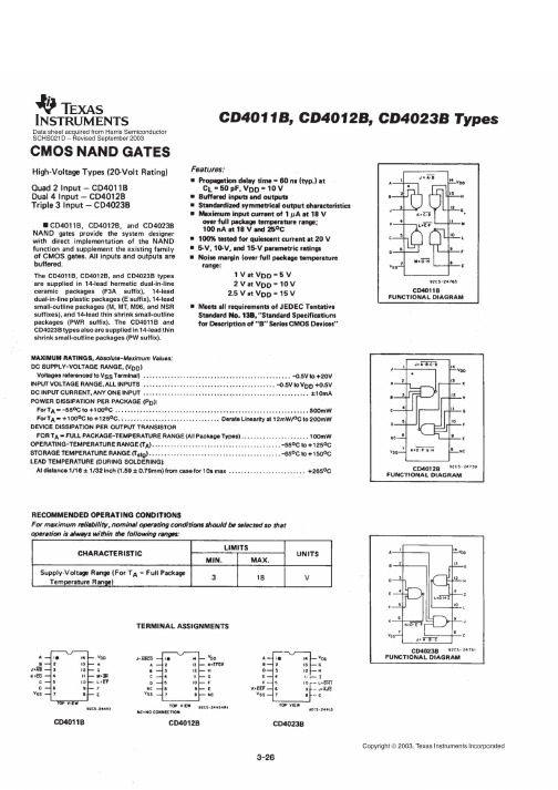
TL F 5939CD4001BM CD4001BC Quad 2-Input NOR BufferedB Series Gate CD4011BM CD4011BC Quad 2-Input NAND Buffered B Series GateMarch1988 CD4001BM CD4001BC Quad2-InputNOR Buffered B Series GateCD4011BM CD4011BC Quad2-InputNAND Buffered B Series GateGeneral DescriptionThese quad gates are monolithic complementary MOS(CMOS)integrated circuits constructed with N-and P-chan-nel enhancement mode transistors They have equal sourceand sink current capabilities and conform to standard B se-ries output drive The devices also have buffered outputswhich improve transfer characteristics by providing veryhigh gainAll inputs are protected against static discharge with diodesto V DD and V SSFeaturesY Low power TTL Fan out of2driving74Lcompatibility or1driving74LSY5V–10V–15V parametric ratingsY Symmetrical output characteristicsY Maximum input leakage1m A at15V over full tempera-ture rangeSchematic DiagramsTL F 5939–1CD4001BC BMTL F 5939–2of device shownJ e A a BLogical‘‘1’’e HighLogical‘‘0’’e LowAll inputs protected by standardCMOS protection circuitTL F 5939–5CD4011BC BMTL F 5939–6of device shownJ e A BLogical‘‘1’’e HighLogical‘‘0’’e LowAll inputs protected by standardCMOS protection circuitC1995National Semiconductor Corporation RRD-B30M105 Printed in U S AAbsolute Maximum Ratings(Notes1and2) If Military Aerospace specified devices are required please contact the National Semiconductor Sales Office Distributors for availability and specifications Voltage at any Pin b0 5V to V DD a0 5V Power Dissipation(P D)Dual-In-Line700mW Small Outline500mWV DD Range b0 5V DC to a18V DC Storage Temperature(T S)b65 C to a150 C Lead Temperature(T L)(Soldering 10seconds)260 C Operating ConditionsOperating Range(V DD)3V DC to15V DC Operating Temperature RangeCD4001BM CD4011BM b55 C to a125 C CD4001BC CD4011BC b40 C to a85 CDC Electrical Characteristics CD4001BM CD4011BM(Note2)Symbol Parameter Conditionsb55 C a25 C a125 CUnits Min Max Min Typ Max Min MaxI DD Quiescent Device V DD e5V V IN e V DD or V SS0 250 0040 257 5m ACurrent V DD e10V V IN e V DD or V SS0 500 0050 5015m A V DD e15V V IN e V DD or V SS1 00 0061 030m A V OL Low Level V DD e5V0 0500 050 05V Output Voltage V DD e10V l I O l k1m A0 0500 050 05V V DD e15V(0 0500 050 05V V OH High Level V DD e5V4 954 9554 95V Output Voltage V DD e10V l I O l k1m A9 959 95109 95V V DD e15V(14 9514 951514 95V V IL Low Level V DD e5V V O e4 5V1 521 51 5V Input Voltage V DD e10V V O e9 0V3 043 03 0V V DD e15V V O e13 5V4 064 04 0V V IH High Level V DD e5V V O e0 5V3 53 533 5V Input Voltage V DD e10V V O e1 0V7 07 067 0V V DD e15V V O e1 5V11 011 0911 0V I OL Low Level Output V DD e5V V O e0 4V0 640 510 880 36mACurrent V DD e10V V O e0 5V1 61 32 250 9mA (Note3)V DD e15V V O e1 5V4 23 48 82 4mA I OH High Level Output V DD e5V V O e4 6V b0 64b0 51b0 88b0 36mACurrent V DD e10V V O e9 5V b1 6b1 3b2 25b0 9mA (Note3)V DD e15V V O e13 5V b4 2b3 4b8 8b2 4mA I IN Input Current V DD e15V V IN e0V b0 10b10b5b0 10b1 0m AV DD e15V V IN e15V0 1010b50 101 0m A Connection DiagramsCD4001BC CD4001BMDual-In-Line PackageTL F 5939–3 Top ViewCD4011BC CD4011BMDual-In-Line PackageTL F 5939–4Top ViewOrder Number CD4001B or CD4011B2DC Electrical Characteristics CD4001BC CD4011BC(Note2)Symbol Parameter Conditionsb40 C a25 C a85 CUnits Min Max Min Typ Max Min MaxI DD Quiescent Device V DD e5V V IN e V DD or V SS10 00417 5m ACurrent V DD e10V V IN e V DD or V SS20 005215m A V DD e15V V IN e V DD or V SS40 006430m AV OL Low Level V DD e5V0 0500 050 05V Output Voltage V DD e10V l I O l k1m A0 0500 050 05V V DD e15V(0 0500 050 05V V OH High Level V DD e5V4 954 9554 95V Output Voltage V DD e10V l I O l k1m A9 959 95109 95V V DD e15V(14 9514 951514 95V V IL Low Level V DD e5V V O e4 5V1 521 51 5V Input Voltage V DD e10V V O e9 0V3 043 03 0V V DD e15V V O e13 5V4 064 04 0V V IH High Level V DD e5V V O e0 5V3 53 533 5V Input Voltage V DD e10V V O e1 0V7 07 067 0V V DD e15V V O e1 5V11 011 0911 0V I OL Low Level Output V DD e5V V O e0 4V0 520 440 880 36mACurrent V DD e10V V O e0 5V1 31 12 250 9mA (Note3)V DD e15V V O e1 5V3 63 08 82 4mA I OH High Level Output V DD e5V V O e4 6V b0 52b0 44b0 88b0 36mACurrent V DD e10V V O e9 5V b1 3b1 1b2 25b0 9mA (Note3)V DD e15V V O e13 5V b3 6b3 0b8 8b2 4mA I IN Input Current V DD e15V V IN e0V b0 30b10b5b0 30b1 0m AV DD e15V V IN e15V0 3010b50 301 0m A AC Electrical Characteristics CD4001BC CD4001BMT A e25 C Input t r t f e20ns C L e50pF R L e200k Typical temperature coefficient is0 3% C Symbol Parameter Conditions Typ Max Units t PHL Propagation Delay Time V DD e5V120250ns High-to-Low Level V DD e10V50100nsV DD e15V3570nst PLH Propagation Delay Time V DD e5V110250ns Low-to-High Level V DD e10V50100nsV DD e15V3570nst THL t TLH Transition Time V DD e5V90200nsV DD e10V50100nsV DD e15V4080nsC IN Average Input Capacitance Any Input57 5pFC PD Power Dissipation Capacity Any Gate14pFAC Parameters are guaranteed by DC correlated testingNote1 ‘‘Absolute Maximum Ratings’’are those values beyond which the safety of the device cannot be guaranteed Except for‘‘Operating Temperature Range’’they are not meant to imply that the devices should be operated at these limits The table of‘‘Electrical Characteristics’’provides conditions for actual device operationNote2 All voltages measured with respect to V SS unless otherwise specifiedNote3 I OL and I OH are tested one output at a time3AC Electrical Characteristics CD4011BC CD4011BMT A e25 C Input t r t f e20ns C L e50pF R L e200k Typical Temperature Coefficient is0 3% C Symbol Parameter Conditions Typ Max Unitst PHL Propagation Delay V DD e5V120250ns High-to-Low Level V DD e10V50100nsV DD e15V3570nst PLH Propagation Delay V DD e5V85250ns Low-to-High Level V DD e10V40100nsV DD e15V3070nst THL t TLH Transition Time V DD e5V90200nsV DD e10V50100nsV DD e15V4080nsC IN Average Input Capacitance Any Input57 5pFC PD Power Dissipation Capacity Any Gate14pF AC Parameters are guaranteed by DC correlated testingTypical Performance CharacteristicsTypicalTransfer CharacteristicsTL F 5939–7TypicalTransfer CharacteristicsTL F 5939–8TypicalTransfer CharacteristicsTL F 5939–9TypicalTransfer CharacteristicsTL F 5939–10TL F 5939–11FIGURE5TL F 5939–12FIGURE64Typical Performance Characteristics (Continued)TL F 5939–13FIGURE 7TL F 5939–14FIGURE 8TL F 5939–15FIGURE 9TL F 5939–16FIGURE 10TL F 5939–17FIGURE 11TL F 5939–18FIGURE 12TL F 5939–19FIGURE 13TL F 5939–20FIGURE 145C D 4001B M C D 4001B C Q u a d 2-I n p u t N O R B u f f e r e d B S e r i e s G a t e C D 4011B M C D 4011B C Q u a d 2-I n p u t N A N D B u f f e r e d B S e r i e s G a t ePhysical Dimensions inches (millimeters)Ceramic Dual-In-Line Package (J)Order Number CD4001BMJ CD4001BCJ CD40011BMJ or CD4011BCJNS Package Number J14AMolded Dual-In-Line Package (N)Order Number CD4001BMN CD4001BCN CD4011BMN or CD4011BCNNS Package Number N14ALIFE SUPPORT POLICYNATIONAL’S PRODUCTS ARE NOT AUTHORIZED FOR USE AS CRITICAL COMPONENTS IN LIFE SUPPORT DEVICES OR SYSTEMS WITHOUT THE EXPRESS WRITTEN APPROVAL OF THE PRESIDENT OF NATIONAL SEMICONDUCTOR CORPORATION As used herein 1 Life support devices or systems are devices or 2 A critical component is any component of a life systems which (a)are intended for surgical implant support device or system whose failure to perform can into the body or (b)support or sustain life and whose be reasonably expected to cause the failure of the life failure to perform when properly used in accordance support device or system or to affect its safety or with instructions for use provided in the labeling can effectivenessbe reasonably expected to result in a significant injury to the userNational Semiconductor National Semiconductor National Semiconductor National Semiconductor CorporationEuropeHong Kong LtdJapan Ltd1111West Bardin RoadFax (a 49)0-180-530858613th Floor Straight Block Tel 81-043-299-2309。
三汇示波器说明书(Ver1.0)
DST4000 和 DST1000 系列数字存储示波器用户手册
i
目录
5.1 显示区 ........................................................................................ 20 5.2 信息区域..................................................................................... 23 5.3 波形显示..................................................................................... 23
三汇系列产品
DST4000 和 DST1000 系列 数字存储示波器
Version 1.0
杭州三汇科技有限公司 www.
目录
目录
目 录 ...........................................................................................................i 版权申明 .......................................................................................................................................................................v 第 1 章 安全事项......................................................................................... 1
泰永2014年产品选型手册
地址:电话:MA60系列智能型万能式断路器MB1,MB1L,MB1G,MB1F-63系列终端电器MB60,MB60Z系列塑壳断路器MA60系列智能型万能式断路器172022263338394345474853555759核心特点:全系列Icu=Ics最高可达150KA,满足更高保护需求国际领先的旋转式双断点结构,大大提升分断能力U型触头结构,限流效果更明显,确保产品的高可靠性精简尺寸,体积更小模块化脱扣器设计,全系列热磁脱扣器与智能脱扣器模块可互换外置漏电模块,方便用户更换及维护M B60系列塑壳断路器135产品总览MB1 系列微型断路器MA60 系列空气断路器MB60 系列塑壳断路器注:需选配C系列智能控制器注:需选配C系列智能控制器)125瞬间并联100A 250A 400A1600A 壳架电流3设计序号(3.4.5)高级型控制器代号CH 为壳架电流H以长九MB1和MB30系列断路器为执行器,壳架电流为63A 、125A 、250A 、630A 可选系列额定工作电流(A )设计代号企业产品型号执行器控制器类型(I 为简易型 为复合型)开关极数(2P 二极 3P 三极 4P 四极)注:转换开关本体为两工作位时,需将控制器设置为两段位自投自复/自投不自复可调,自投自复不可设置;;T BF-T1TBF-M1TBF-T2TBF-K1TBF-M1TBF-M1TBF -Z1T BF-T3T BF-T1T BF-M3隔离模块双回路监控探测器代号注:TBF-K1可测量两路漏电及两路温度,且必须与TBF-T1或TBF-T2配合使用。
温度传感器控制模块隔离模块组合式探测器K1MA40 系列MA40 系列M A 40 系列M A 450 系列MA450 系列注:1、合分电类型为内部附件的控制电压,合:合闸线圈,分:分励线圈,电:电动机储能机构,为必须选配附件。
2、用户极数选择3P+N 时需要加N相外接互感器。
MA 60 M - 4000 R3200 M / 3 FHVR NST + YU230 D1短路分断能力可选代号:M 标准型H 高分断型安装方式代号:FHHR :固定式上下水平 FHVR :固定式上平下竖 FVHR :固定式上竖下平 FVVR :固定式上下竖直 WHHR :抽屉式上下水平 WHVR :抽屉式上平下竖 WVHR :抽屉式上竖下平 WVVR :抽屉式上下竖直压脱扣器类型代号:空 不具备欠压脱扣器YU230 欠压脱扣器AC230V YU400 欠压脱扣器AC400V欠额定电流壳架等级额定电流可选代号:Inm =1600=2500=4000=6300Inm Inm Inm 智能控制器代号:M :Adaptcan 6A11基本型H :Adaptcan 6A12高级型极数代号:3: 3极4: 4极5: 3极+N (见注)合分电类型代号:(见注)NST 合分电AC230V DST 合分电DC230V OST 合分电AC400V 欠压延时时间代号:空 瞬时型D1 延时1s D3 延时3s D5 延时5s短路分断能力合分电类型欠压延时技术参数表技术参数表MA60 系列M A 60 系列技术参数表MA60 系列M A 60 系列MB60 MB60ZMB 60 S - 250 R 16 / 3 3 00 2 D A FF短路分断能力可选代号:S 标准型M 较高分断型H 高分断型壳架等级额定电流可选代号:Inm =250Inm =630额定电流脱扣方式代号:2:只有短路保护3:有短路,过载保护附件代号:“见附件表”用途代号:2 电机保护空 配电保护操作方式代号:D 电操Z 手操空 无安装方式代号:FF: 固定式,板前接线PR: 插入式,板后接线DR: 抽出式,板后接线注:250壳架无抽出式极数代号:3三极4四极::3极产品为空4极产品N极型式A :N 极直通,且不带保护B :N 极分断,且不带保护C :N 极分断,且带保护D :N 极直通,且带保护MB60 系列系列塑壳断路器MB60Z S - 250 R250 / 3 3 00 2 D A FF + 6B11 F0短路分断能力可选代号:S 标准型M 较高分断型H 高分断型额定电流脱扣方式代号:2:只有短路保护3:有过载和短路 保护操作方式代号:D 电动操作Z 手动操作机构空 无安装方式代号:FF: 固定式,板前接线PR: 插入式,板后接线DR: 抽出式,板后接线注:250壳架无抽出式附加功能代号:F0 基本型F1 组网型注:6B11才能选配 F1组网型附件壳架等级额定电流可选代号:Inm =250Inm =630极数代号:3 三极4 四极附件代号:“见附件表”用途代号:2 电动机保护空 配电保护电子脱扣器代号:6B11 基本型6B12 智能型3极产品为空4极产品N极型式A :N 极直通,且不带保护B :N 极分断,且不带保护C :N 极分断,且带保护D :N 极直通,且带保护电子脱扣器功能表MB60 系列M B 60Z 系列MB60 MB60Z 系列塑壳断路器技术参数表MB60 MB60Z 系列塑壳断路器MB 1F -63M B 60Z 系列附件代号MB60 MB60Z 系列塑壳断路器MB 1 F -63/4过欠压功能额定电流(32A 40A 50A 63A)MB 1F -63MB1,MB1L ,MB1G ,MB1F -63系列M B 1 系列M G 1 系列04代表4极接触器(不自带辅助触头) 65。
cd4011中文资料_数据手册_参数
电子元器件物料采购找万联芯城,专业电子 元器件配单,万联芯城专为终端客户提供电子元器件配单业务, 货源均来自原厂及代理商,万联芯城BO报价-下单-商城发货,万联芯城拥有完 善的产品供应链体系及现代化仓储系统,可满足多种BOM报价需 求,点击进入万联芯城。
CD4001BMCD4001BC四2-InputNOR缓冲B系列GateCD4011BMCD4011BC四2-InputNAND缓冲B系列GateGeneral DescriptionThese四门整 体互补金属氧化物半导体(CMOS)集成电路构造与N - P-chan-nel增强型晶体管他们平等sourceand反向电流能力和符合标准B se-ries输出 驱动设备也有缓冲outputswhich改善传输特性通过提供veryhigh gainAll输入保护对 静电 放电 与 diodesto VDD VSSFeaturesYLow 权力 TTLFan 2 驾驶 74 Lcompatibilityor 驾驶 74 LSY5V – 10 V – 15 V 参数 ratingsYSymmetrical 输出 characteristicsYMaximum 输入 漏 1 mA 15 V 完整 tempera-ture rangeSchematic DiagramsTLF5939 – 1 CD4001BCBMTLF5939 – 2 设备 shownJ e A BLogical ‘‘1’’ e HighLogical ‘‘0’’ e LowAll 输入 保护 standardCMOS 保护 circuitTLF5939 – 5 CD4011BCBMTLF5939 – 6 设备 shownJ e A BLogical ‘‘1’’ e高 逻辑“0”e低所有输入由标准cmos保护电路保护CD4011 NAND门为系统设计人员提供了NAND功能的直接实现。Features Operating Voltage Range: 3.0 到 18 V Maximum 输入 电流 1 在 18 V 全 包 100 - 141 温度 范围 nA 18 岁 V 25 C° Noise 保证金 (over 满 管 温度 range):1.0 V 5.0 分钟 @ V supply2.0 V 10.0 分钟 @ V supply2.5 V 15.0 分钟 @ V 供应
LC1-D4011交流接触器
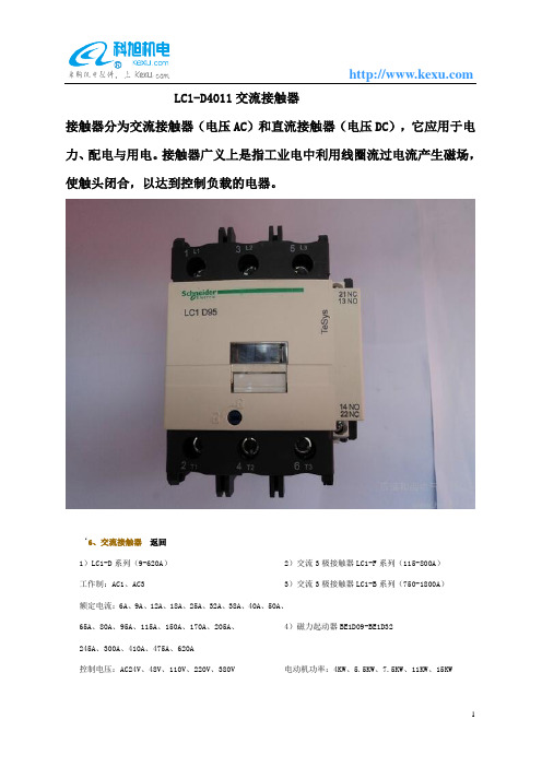
LC1-D4011交流接触器接触器分为交流接触器(电压AC)和直流接触器(电压DC),它应用于电力、配电与用电。
接触器广义上是指工业电中利用线圈流过电流产生磁场,使触头闭合,以达到控制负载的电器。
‘6、交流接触器返回1)LC1-D系列(9-620A)2)交流3极接触器LC1-F系列(115-800A)工作制:AC1、AC3 3)交流3极接触器LC1-B系列(750-1800A)额定电流:6A、9A、12A、18A、25A、32A、38A、40A、50A、4)磁力起动器BE1D09-BE1D32 65A、80A、95A、115A、150A、170A、205A、245A、300A、410A、475A、620A控制电压:AC24V、48V、110V、220V、380V 电动机功率:4KW、5.5KW、7.5KW、11KW、15KW5)3极可逆接触器LC2-D系列(9A-630A)6)星三角起动器LC3-D系列(9A—400A)8)单极、2、3、4极7)两极和四极交流接触器LC1-D系列(9A—780A)接触器(800-2750A)7、直流接触器返回1)LP1-D系列(9A-800A)、LP1-F系列(115A-800A)2)2极、4极直流接触器额定电流:9A、12A、18A、25A、32A、40A、10A、65A、80A、额定电流:12A、25A、40A、65A、80A、115A、150A、115A、150A、185A、225A、265A、330A、400A、500A、630A、185A、225A、265A、330A、400A、500A、630A、780A 800A控制电压:DC24V、48V、110V、220V、380V 控制电压:DC24V、48V、110V、125V、220V、250V8、热继电器返回1)LR2-D系列2)LR9-系列调节范围:0.1-150A 调节范围:3A-630A9、电动机保护空气开关返回1)GV2-M、GV2-RS系列热保护范围:0.1-32A2)电磁电动机空气开关GV2-LS系列热保护范围:0.4-25A3)电动机起动器(K接触器+GV2)GA2-M系列法国施耐德型号名称技术参数辅助接点LC1-D0610*5N N系列接触器380VAC/6A 2.2KW1NOCA2-DN40*5N N系列中间继电器4NOLR2-D1301N N系列热继电器0.1~0.16ALC1-D0910**C A、D系列接触器、热继电器380V AC/9A 4KW INOCA2-DN40**C D系列中间继电器4NOLR2-D1301C D系列热继电器0.10~0.16A D09-D32适用LA1-DN22C接触器附件--辅助触头2NO+2NC 配用LC1-D09-F780 LP1-D09-F780装LA2-DT0C接触器附件---延时头延时通0.1~3SLA9-D09978接触器附件--机械联锁装置D09-D32适用水平安装LA7-D1064接触器附件--热继电器安装支架LR2-D1…适用GB2-GB05空气开关---单极空气开关0.5A导轨安装GB2-CD05空气开关--两极空气开关0.5A导轨安装NSD100 带热磁脱扣器空气开关---三极空气开关25、40、50、63、80、100AGV2-M01C GV2-RS01C 空气开关---带热保护三相电动机空气开关热保0.1~0.16AXB2-EA121XB2-E系列按钮(黑)圆型平头按钮1NOXB2-EW3361XB2-E系列-带灯按钮(不含灯泡)(绿)直接式带灯按钮1NOXB2-ED21XB2-E系列-选择开关二位置选择开关自锁1NO。
DKS 产品说明书

Member:
VEHICULAR AC & DC
SLIDE GATE OPERATORS
Residential • Apartment/College Residence Halls • Gated Communities Mixed Use Buildings • Commercial/Industrial • Parking • Self Storage
protection devices.
DC/Solar 9024
Operator is 24 Volt DC and includes built-in battery backup 115/230 VAC (switch selectable) or 24 VDC Solar Power 1/2 HP Quadra Drive Heavy-duty DC motor. Heavy-duty 30:1 ratio gearbox. Solar power ready, with 0.0 Amp SBPD Circuit.
Upon a power outage, these operators “fail” in a “safe” condition allowing the gate to be pushed open without any special keys, cranks or special knowledge. This is a requirement by many fire department authorities throughout the country.
LSA过电压保护器-LCK消弧消谐柜
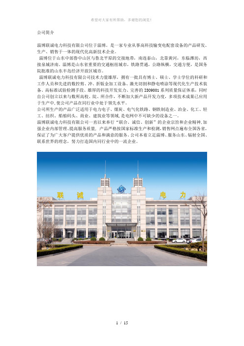
公司简介淄博联诚电力科技有限公司位于淄博。
是一家专业从事高科技输变电配套设备的产品研发、生产、销售于一体的现代化高新技术企业。
淄博位于山东中部鲁中山区与鲁北平原的交接地带,南连泰山,北靠黄河,东临潍坊,西接泉城济南。
淄博是山东省重要的交通枢纽城市,铁路贯通,公路纵横,交通方便,是国务院批准的山东半岛经济开放区城市。
淄博联诚电力科技有限公司技术力量雄厚,拥有一批具有博士、硕士、学士学位的科研和工作人员和先进的数控剪、冲、折钣金加工设备、激光切割和静电喷涂等现代化生产技术装备、高标准试验检测手段、雄厚的科技开发实力、完善的ISO9001系列质量保证体系,同时自公司创立以来与数所高校、院、所合作,不断加大新产品开发力度,多项技术成果已应用于生产中,使公司产品在同行业中处于领先水平。
公司所生产的产品广泛适用于电力电子、煤炭、电气化铁路、钢铁制造业、冶金、化工、轻工、纺织、船舶码头、商业、建筑业等领域,是电网中不可缺少的设备之一。
淄博联诚电力科技有限公司一直以来奉行“联合、诚信、创新”的企业宗旨和企业精神,加强企业内部管理、提高服务质量, 产品严格按国家标准生产和检测,销售网点遍布全国各省,保证了为广大客户提供优质的产品和满意的服务。
公司本着立足淄博、服务山东、辐射全国、联系世界的理念,努力打造国内同行业中的一流企业。
用途LSA组合式过电压保护器,主要用于电力、化工、冶金、矿山、油田、煤矿、建筑等行业中性点非有效接地系统中,保护变压器、开关、母线、发电机、电动机、电炉、电解槽等电气设备,既能保护相地绝缘,又能保护相间绝缘,对大气过电压及各种真空开关引起的操作过电压均能起到保护作用。
型号说明、本系列产品的工作元件采用组合式结构,内部各单元均为单独密封单元,外部采用高压绝缘材料再次密封对外绝缘,产品外壳不带电,仅有四个接线端子,产品为整件,结构紧凑,其型号命名为:原理介绍如图所示,在工频状态下,放电间隙实际上只是一个容量极小的电容,这时电路中只有微小的容性电流通过,没有阻性电流,也就是说A相、B相、C相电源电压是由JA、JB、JC三个间隙承担的,三个间隙的下端对地之间是由纯ZnO阀片组成,工频状态下具有相同的电位。
PES-F100智能保护测显装置说明书V2.0.0

普尔盾电气(上海)有限公司PES-F100智能保护测显装置技术及使用手册【适用于110kv及以下电压等级电网的保护、控制、测量和监视。
可用于不同的主接线方式,如单母线,双母线及多母线方式接线;支持不同类型的电网,如中性点不接地系统,经消弧线圈接地系统和小电阻接地系统。
】感谢您选用PES-F100系列智能保护测显装置。
我们建议在安装和使用PES-F100系列智能保护测显装置之前请仔细阅读本手册。
请将本手册妥善存放,以备您将来的使用。
订货前,请垂询本公司或当地经销商以获悉本产品的最新规格。
本手册当前版本V2.0.0目录1 概述 (1)1.1 适用范围 (1)1.2 逻辑可编程功能 (1)1.3 友好的人机交互 (1)1.4 高可靠性设计 (2)1.5 高精度测量 (2)1.6 全面的事故分析记录 (2)1.7 精准的校时 (2)1.8 实时数据打印功能 (2)1.9 强大灵活的通讯 (2)2 技术参数 (3)2.1 环境条件 (3)2.2 工作电源 (3)2.3 控制电源 (3)2.4 交流电流回路 (3)2.5 交流电压回路 (3)2.6 开关量输入回路 (3)2.7 继电器输出回路 (4)2.8 测量及计量精度 (4)2.9 绝缘性能 (4)2.10 电磁兼容性 (4)2.11 机械性能 (5)2.12 装置接口资源 (5)2.13 通讯功能详述 (5)3 保护原理 (5)3.1 过流一段保护 (5)3.2 过流二段保护 (6)3.3 定时限过流三段保护 (7)3.4 反时限过流三段保护 (8)3.5 保护选项:方向闭锁 (9)3.6 保护选项:零序方向闭锁 (10)3.7 过负荷保护 (10)3.8 合环保护 (11)3.9 合环零序保护 (11)3.10 零序电流保护 (12)3.11 PT断线报警 (12)3.12 线路抽取电压异常 (13)3.13 母线接地保护 (13)3.14 低压侧零序过流保护 (13)3.15 低电压保护 (14)3.16 重合闸保护 (14)3.17 重合闸后加速保护 (16)3.18 低频减载保护 (17)3.19 过电压保护 (18)3.20 过热保护 (19)3.21 负序电流保护 (20)3.22 逆功率保护 (20)3.23 失步保护 (21)3.24 三段式磁平衡保护 (21)3.25 启动时间过长保护 (22)3.26 充电保护 (23)3.27 不平衡电压保护 (23)3.28 不平衡电流保护 (24)3.29 间隙过流保护 (24)3.30 非电量保护 (25)3.31 故障录波 (25)4 整定说明 (25)4.1 保护功能投退控制字表 (25)4.1.1 线路保护投退控制字 (25)4.1.2 配电变保护投退控制字 (26)4.1.6 变压器后备保护投退控制字 (29)4.1.7 同步电动机保护投退控制字 (29)4.2 保护定值整定表 (30)4.2.1 线路保护定值整定表 (30)4.2.2 配电变保护定值整定表 (31)4.2.3 异步电动机保护定值整定表 (32)4.2.4 电容器保护定值表 (33)4.2.5 母联保护定值整定表 (34)4.2.6 变压器后备保护定值整定表 (34)4.2.7 同步电动机保护定值整定表 (35)4.3 监控参数定值表 (36)4.4 事故记录表(SOE) (36)4.4.1 线路保护SOE (36)4.4.2 配电变保护SOE (37)4.4.3 异步电动机保护SOE (37)4.4.4 电容器保护SOE (38)4.4.5 母联保护SOE (38)4.4.6 变压器后备保护SOE (38)4.4.7 同步电动机保护SOE (39)5 安装与接线 (39)5.1 安装 (39)5.2 接线 (40)5.2.1 高亮度LED指示灯 (40)5.2.2 “确认”按键 (41)5.2.3 “复归”按键 (41)5.2.4 “方向”按键.............................................................................................................. 错误!未定义书签。
速控器标准型型 elbow 型(金属体)说明书

Doc. no. AS*-OMW0046-ASPEED CONTROLLER STANDARD TYPEELBOW TYPE (METAL BODY)AS1400-M3AS12*0~AS42*01.Safety Instructions 2 ~3 2.Specific Product Precautions 4 ~6 3.Application 7 4.Specifications 7 5.Troubleshooting 7 6.Construction 8-1-Speed Controller Standard TypeElbow Type (Metal Body) / AS SeriesSafety InstructionsThese safety instructions are intended to prevent hazardous situations and/or equipment damage.These instructions indicate the level of potential haz ard with the labels of “Caution,” “Warning” or “Danger.”They are all important notes for safety and must be followed in addition to International Standards (ISO/IEC)*1) , and other safety regulations.*1) ISO 4414: Pneumatic fluid power -- General rules relating to systems.ISO 4413: Hydraulic fluid power -- General rules relating to systems.IEC 60204-1: Safety of machinery -- Electrical equipment of machines .(Part 1: General requirements)ISO 10218: Manipulating industrial robots -Safety.etc.Caution Caution indicates a hazard with a low level of risk which, if not avoided, could result in minor or moderate injury.Warning Warning indicates a hazard with a medium level of risk which, if not avoided, couldresult in death or serious injury.Danger Danger indicates a hazard with a high level of risk which, if not avoided, will resultin death or serious injury.Warning1. The compatibility of the product is the responsibility of the person who designs the equipment or decides its specifications.Since the product specified here is used under various operating conditions, its compatibility with specific equipment must be decided by the person who designs the equipment or decides its specifications based on necessary analysis and test results.The expected performance and safety assurance of the equipment will be the responsibility of the person who has determined its compatibility with the product.This person should also continuously review all specifications of the product referring to its latest catalog information, with a view to giving due consideration to any possibility of equipment failure when configuring the equipment.2. Only personnel with appropriate training should operate machinery and equipment.The product specified here may become unsafe if handled incorrectly.The assembly, operation and maintenance of machines or equipment including our products must be performed by an operator who is appropriately trained and experienced.3. Do not service or attempt to remove product and machinery/equipment until safety is confirmed.1.The inspection and maintenance of machinery/equipment should only be performed after measures toprevent falling or runaway of the driven objects have been confirmed.2.When the product is to be removed, confirm that the safety measures as mentioned above are implementedand the power from any appropriate source is cut, and read and understand the specific product precautions of all relevant products carefully.3. Before machinery/equipment is restarted, take measures to prevent unexpected operation and malfunction.4. Contact SMC beforehand and take special consideration of safety measures if the product is to be used in any of the following conditions.1. Conditions and environments outside of the given specifications, or use outdoors or in a place exposed todirect sunlight.2. Installation on equipment in conjunction with atomic energy, railways, air navigation, space, shipping,vehicles, military, medical treatment, combustion and recreation, or equipment in contact with food and beverages, emergency stop circuits, clutch and brake circuits in press applications, safety equipment or other applications unsuitable for the standard specifications described in the product catalog.3. An application which could have negative effects on people, property, or animals requiring special safetyanalysis.e in an interlock circuit, which requires the provision of double interlock for possible failure by using amechanical protective function, and periodical checks to confirm proper operation.Speed Controller Standard TypeElbow Type (Metal Body) / AS SeriesSafety InstructionsCaution1. The product is provided for use in manufacturing industries.The product herein described is basically provided for peaceful use in manufacturing industries.If considering using the product in other industries, consult SMC beforehand and exchange specifications or a contract if necessary.If anything is unclear, contact your nearest sales branch.Limited warranty and Disclaimer/Compliance RequirementsThe product used is subject to the following “Limited warranty and Disclaimer” and “Compliance Requirements”.Read and accept them before using the product.Limited warranty and Disclaimer1. The warranty period of the product is 1 year in service or 1.5 years after the product is delivered, whichever is first.Also, the product may have specified durability, running distance or replacement parts. Please consult your nearest sales branch.2. For any failure or damage reported within the warranty period which is clearly our responsibility,a replacement product or necessary parts will be provided.This limited warranty applies only to our product independently, and not to any other damage incurred due to the failure of the product.3. Prior to using SMC products, please read and understand the warranty terms and disclaimersnoted in the specified catalog for the particular products.Compliance Requirements1. The use of SMC products with production equipment for the manufacture of weapons of massdestruction(WMD) or any other weapon is strictly prohibited.2. The exports of SMC products or technology from one country to another are governed by therelevant security laws and regulation of the countries involved in the transaction. Prior to the shipment of a SMC product to another country, assure that all local rules governing that export are known and followed.CautionSMC products are not intended for use as instruments for legal metrology.Measurement instruments that SMC manufactures or sells have not been qualified by type approval tests relevant to the metrology (measurement) laws of each country.Therefore, SMC products cannot be used for business or certification ordained by the metrology (measurement) laws of each country.2. Specific Product PrecautionsWarning(1) Confirm the specifications.Do not operate at pressures, temperatures, etc., beyond the range of specifications, as this can cause damage or malfunction. (Refer to the specifications.)Please contact SMC when using a fluid other than compressed air (including vacuum).We do not guarantee against any damage if the product is used outside of the specifications range.(2)Products mentioned in this catalog are not designed for use as stop valves with zero air leakage.A certain amount of leakage is allowed in the products specifications. Tightening the needle to reduce leakage to zero may result in equipment damage.(3)Do not disassemble the product or make anymodifications, including additional machining.Doing so may cause human injury and/or an accident.(4)The flow rate characteristics for eachproduct are representative values.The flow rate characteristics are characteristics of each individual product. Actual values may differ depending on the piping, circuitry, pressure conditions, etc. Also, depending on product specifications, there may be variations in the zero needle rotations position of the flow rate characteristics.(5)Check if that PTFE can be used in application.PTFE powder (Polytetrafluoroethylene resin) is included in the seal material for piping taper thread of male thread type. Confirm that the use of it will not cause any adverse effect on the system.Please contact SMC if the Safety Data Sheet (SDS) is required.Warning(1) Operation ManualInstall the products and operate it only after reading the operation manual carefully and understanding its contents. Also, keep the manual where it can be referred to as necessary.Warning(2)Ensure sufficient space for maintenance activities.When installing the products, allow access for maintenance.(3)Confirm that the lock nut is tightened.A loose lock nut may cause speed changes in the actuator.(4)Check the degree of rotation of the needlevalve.The Products in this catalog are retainer type so that the needle is not removed completely. Over rotation will cause damage.(5)Do not use tools such as pliers to rotate theknob.This can cause idle rotation of the knob or damage.(6) Confirm the air flow direction.Mounting backward is dangerous, because the speed adjustment needle will not work and the actuator may lurch suddenly.(7) Adjust the needle by opening the needle slowly after having closed it completely.Loose needle valves may cause unexpected sudden actuator lurching.When a needle valve is turned clockwise, it is closed and cylinder speed decreases. When a needle valve is turned counterclockwise, it is open and cylinder speed increases.(8)Do not apply excessive force or shock to the body or fittings with an impact tool. This can cause damage or air leakage.(9)Tighten threads with the proper tightening torque.When installing the products, follow the listed proper torque.(10)For installation/removal, please tighten the hexagonal width across flats of Body B (AS1400-M3: joint) with an appropriate spanner.Do not apply torque at other points as the product may be damaged. For AS22*0~AS42*0, the Body A can be rotated after installation.Design/ SelectionMountingMountingCaution(1) Tightening methodThe proper tightening torques of the fitting are as shown in the table below. As a guide, tighten by hand, then turn it two or three turns with a wrench. Pay attention not to over tighten the product. Check the dimensions of each product for the hexagon width across flats.(2)The proper tightening torques for hexagonlock nuts are shown in the table below. For standard installation, turn 15 to 30゜using a tool after fastening by hand.Pay attention not to over tighten the product. Check the dimensions for each product for the width across flats.Caution(1)Refer to the Fittings & Tubing Precautions for handing One-touch fittings.(2) Preparation before pipingBefore piping is connected, it should be thoroughly blown out with air (flushing) or washed to remove chips, cutting oil and other debris from inside the pipe.(3)Winding of sealant tapeWhen screwing together pipes and fittings, etc., be certain that chips from the pipe threads and sealing material do not get inside the pipe. Also, when the sealant tape is used, leave approx. 1 thread ridges exposed at the end of the threads.Warning(1) Type of fluidsPlease consult with SMC when using the product in applications other than compressed air.(2) When there is a large amount of drainage Compressed air containing a large amount of drainage can cause the malfunction of pneumatic equipment. An air dryer or water separator should be installed upstream from filters.(3) Drain flushingIf condensation in the drain bowl is not emptied on a regular basis, the bowl will overflow and allow the condensation to enter the compressed air lines. This causes the malfunction of pneumatic equipment.If the drain bowl is difficult to check and remove, the installation of a drain bowl with an auto drain option is recommended.For compressed air quality, refer to SMC catalog "Compressed Air Purification System".(4) Use clean airDo not use compressed air that contains chemicals, synthetic oils that include organic solvents, salt, corrosive gases, etc., as it can cause damage or malfunction.Caution(1) Install an air filter.Install an air filter upstream near the valve. Select an air filter with a filtration size of 5μm or smaller.(2)Take measures to ensure air quality, such as by installing an aftercooler, air dryer, or water separator.Compressed air that contains a large amount of drainage can cause the malfunction of pneumatic equipment, such as flow control equipment. Therefore, take appropriate measures to ensure air quality, such as by providing an aftercooler, air dryer, or water separator.(3) Ensure that the fluid and ambient temperatures are within the specified range. If the fluid temperature is 5℃ or less, the moisture in the circuit could freeze, causing damage to the seals or leading to equipment malfunction. Therefore, take appropriate measures to prevent freezing.For compressed air quality, refer to SMC catalog "Compressed Air Purification System".Air SupplyPiping MountingOperating environmentWarning(1) Do not use in an atmosphere containing corrosive gases, chemicals, sea water, water, water steam, or where there is direct contact with any of these.Refer to each construction drawing for information on the materials of flow control equipment.(2) Do not expose the product to direct sunlightfor an extended period of time.(3) Do not use in a place subject to heavy vibration and/or shock.(4) Do not mount the product in locations where it is exposed to radiant heat.MaintenanceWarning(1)Perform maintenance and inspection according to the procedures indicated in the operation manual.If handled improperly, malfunction or damage of machinery and equipment may occur.(2) Maintenance workIf handled improperly, compressed air can be dangerous.Assembly, handling, repair and element replacement of pneumatic systems should be performed by a knowledgeable and experienced person.(3) Drain flushingRemove drainage from air filters regularly. (4) Removal of equipment, andsupply/exhaust of compressed airBefore components are removed, first confirm that measures are in place to prevent workpieces from dropping, run-away equipment, etc.Then, Cut the supply pressure and electric power, and exhaust all compressed air from the system using the residual pressure release function.When machinery is restarted, proceed with caution after confirming that appropriate measures are in place to prevent sudden movement.3. ApplicationThis product is designed to control the speed of a pneumatic actuator.4. Specifications5.Troubleshooting6.ConstructionAS1400-M34-14-1, Sotokanda, Chiyoda-ku, Tokyo 101-0021 JAPANTel: + 81 3 5207 8249 Fax: +81 3 5298 5362URL https://Note: Specifications are subject to change without prior notice and any obligation on the part of the manufacturer. © 2022 SMC Corporation All Rights Reserved。
电力防御系列产品的产品说明书

Eaton PDD32P0125TFAKPower Defense UL/CSA 240V Max, Frame 3, Two Pole, 125A, 200kA/240V, T-M (Fxd-Adj) TU, Std Term Line Only (PDG3X2TA300)Eaton Power Defense molded case circuit breakerPDD32P0125TFAK 786679988152109.1 mm 257.1 mm 138.9 mm 5.2163 kg Eaton Selling Policy 25-000, one (1) year from the date of installation of theProduct or eighteen (18) months from thedate of shipment of the Product,whichever occurs first.RoHS Compliant CSAUL 489Product NameCatalog Number UPCProduct Length/Depth Product Height Product Width Product Weight WarrantyCompliancesCertifications125 AComplete breaker 3Two-polePD3 UL/CSA Only Class A T-M (Fxd-Adj) TU240 V AC240 VStandard Terminals Line Only200 kAIC at 240 Vac 200 kAIC @240V (UL) 22 kAIC Icu @250 VdcEaton Power Defense PDD32P0125TFAK 3D drawing Consulting application guide - molded case circuit breakers StrandAble terminals product aid Power Defense technical selling booklet Power Defense brochurePower Defense molded case circuit breaker selection poster PDG3 UL authorization 100-400a PDG3 UL authorization 250-600a TMTUAmperage Rating Circuit breaker frame type Frame Number of poles Circuit breaker type Class Trip Type Voltage rating Voltage rating - max TerminalsInterrupt rating Interrupt rating range 3D CAD drawing packageApplication notesBrochuresCertification reportsEaton Corporation plc Eaton House30 Pembroke Road Dublin 4, Ireland © 2023 Eaton. All Rights Reserved. Eaton is a registered trademark.All other trademarks areproperty of their respectiveowners./socialmediaPower Defense Declaration concerning California’s Proposition 65Power Defense Frame 3 Breaker Instructions (IL012107EN).pdf Power Defense Frame 3 Variable Depth Rotary Handle Mechanism Installation How-To Video Power Defense BreakersPower Defense Frame 6 Trip Unit How-To Video Eaton Power Defense for superior arc flash safety Power Defense molded case circuit breakersPower Defense Frame 2 Variable Depth Rotary Handle Mechanism Installation How-To VideoPower Defense Frame 5 Trip Unit How-To Video Eaton Specification Sheet - PDD32P0125TFAK Power Defense time current curve Frame 3 - PD3Molded case and low-voltage breaker health Safer by design: arc energy reduction techniquesInstallation instructionsMultimediaSpecifications and datasheetsTime/current curvesWhite papers。
vcs4011 智能电力监控仪说明书v20
VCS4011智能电力监控仪说明书V2.00江苏威信电气科技有限公司2014年2月*本说明书可能会被修改,请注意核对实际产品于说明书版本是否相符*江苏威信电气科技有限公司保留对所有资料的修改和解释权1.概述1.1适用范围VCS4011智能电力监控仪是针对电力系统、工矿企业、石油化工、钢铁冶金、轨道交通、公用设施、智能建筑等自动化水平要求较高的电力监控需求而设计的。
仪表主要功能:三相交流电量测量、电能计量、谐波分析、越限告警、综合显示、开关量输入、遥控输出、网络通讯于一体。
仪表的场合:电能量管理系统、工业自动化、小区电力监控、变电站自动化、配电网自动化、智能化楼寓、智能型配电盘、开关柜1.2特点⏹交直流通用电源宽电压输入的AC/DC通用电源,电压输入范围86~275V。
⏹交流电流、电压测量三相交流电流测量,额定电流5A,精度0.2级;三相交流电压测量,额定电压220V、100V或57.74V,相电压和线电压自动转换,精度0.2级;⏹功率测量三相有功功率及总有功功率三相无功功率及总无功功率;三相视在功率及总视在功率;⏹电能测量三相有功电能及无功电能;有功电能精度为0.5级;无功电能为1级;⏹数据统计19次谐波统计;仪表显示总谐波,其余各相电流、电压的各次谐波需通过通讯方式读取;电流、电压的最大值、最小值、平均值;⏹继电器输出(选配)2路继电器输出,输出方式为无源接点;各继电器输出内容可设置为遥控、过流告警或过负荷告警;继电器输出容量为AC220V,5A;⏹开关量输入(选配)4路开关量输入,电源为仪表自带DC24V,隔离方式为光电隔离;开关量输入响应速度为2ms;⏹脉冲输出(选配)2路电能脉冲(有功电能、无功电能)输出,输出方式为光电隔离,输出脉冲对应二次侧电能;电能卖出输出精度:有功电能脉冲0.5级,无功电能脉冲1级。
⏹时钟及通讯实时日期及时钟显示,支持网络对时;RS485通讯接口,内嵌DL/645及MODBUS两种通讯协议,可设置;⏹外形及安装外型小巧,尺寸与国际标准兼容;采用自锁式的安装机构,无螺丝,安装拆卸方便快捷;⏹显示直观、易学易用采用定制的带背光液晶显示,显示内容多且直观,可直接设置变比显示一次侧电力参数。
美国Eaton公司产品说明书:Eaton Moeller ZB过载保护器ZB12-6-GVP

Eaton 116312Eaton Moeller® series ZB Overload relay, ZB12, Ir= 4 - 6 A, 1 N/O, 1 N/C, Direct mounting, IP20, big packEaton Moeller® series ZB Thermal overload relay116312ZB12-6-GVP401508116039688 mm 67 mm 45 mm 0.152 kgCE marking ULUL Category Control No.: NKCR VDE 0660CSA Class No.: 3211-03 CSA-C22.2 No. 60947-4-1-14 IEC/EN 60947-4-1 UL Listed IEC/EN 60947 CSA certified UL File No.: E29184 UL 60947-4-1 CSA File No.: 012528 CSAProduct NameCatalog Number Model Code EANProduct Length/Depth Product Height Product Width Product Weight CertificationsReset pushbutton manual/autoPhase-failure sensitivity (according to IEC/EN 60947, VDE 0660 Part 102)Trip-free release -25 °C55 °C25 °C40 °CCLASS 10 ADamp heat, cyclic, to IEC 60068-2-30Damp heat, constant, to IEC 60068-2-78IP20ZB12Direct mounting4 A6 AIII3Overload relay ZB up to 150 AFinger and back-of-hand proof, Protection against direct contact when actuated from front (EN 50274)6000 V AC4000 V (auxiliary and control circuits)Features Ambient operating temperature - minAmbient operating temperature - maxAmbient operating temperature (enclosed) - minAmbient operating temperature (enclosed) - maxClassClimatic proofingDegree of protectionFrame sizeMounting methodOverload release current setting - minOverload release current setting - maxOvervoltage categoryPollution degreeProduct categoryProtectionRated impulse withstand voltage (Uimp)Shock resistance10 g, Mechanical, Sinusoidal, Shock duration 10 ms Branch circuits, (UL/CSA)≤ 0.25 %/K, residual error for T > 40° Continuous 1 x (1 - 4) mm², Main cables2 x (1 - 4) mm², Main cables1 x (0.75 - 2.5) mm², Control circuit cables2 x (0.75 - 2.5) mm², Control circuit cables1 x (0.75 - 4) mm², Control circuit cables2 x (0.75 - 4) mm², Control circuit cables2 x (1 - 6) mm², Main cables1 x (1 - 6) mm², Main cables18 - 8, Main cables2 x (18 - 14), Control circuit cables10 mm8 mmM3.5, Terminal screwM4, Terminal screw2, Terminal screw, Pozidriv screwdriver1 x 6 mm, Terminal screw, Control circuit cables, Standard screwdriver1.8 Nm, Screw terminals, Main cables1.2 Nm, Screw terminals, Control circuit cables6 A 1.5 A 1.5 A 0.9 A 100 kA, Fuse, SCCR (UL/CSA)10 A, Class J/CC, max. Fuse, SCCR (UL/CSA)Max. 6 A gG/gL, Fuse, Contacts25 A gG/gL, Fuse, Type “1” coordination20 A gG/gL, Fuse, Type “2” coordinationSuitable forTemperature compensationTerminal capacity (flexible with ferrule)Terminal capacity (solid)Terminal capacity (solid/stranded AWG)Stripping length (main cable)Stripping length (control circuit cable)Screw sizeScrewdriver sizeTightening torqueConventional thermal current ith of auxiliary contacts (1-pole, open)Rated operational current (Ie) at AC-15, 120 VRated operational current (Ie) at AC-15, 220 V, 230 V, 240 V Rated operational current (Ie) at AC-15, 380 V, 400 V, 415 V Short-circuit current rating (high fault at 600 V) Short-circuit protection rating0.4 A0.2 A0.9 A0.75 A690 V440 V AC, Between auxiliary contacts and main contacts, According to EN 61140240 V AC, Between auxiliary contacts, According to EN 61140B600 at opposite polarity, AC operated (UL/CSA)R300, DC operated (UL/CSA)B300 at opposite polarity, AC operated (UL/CSA)600 VAC600 VAC 011115.1 W0 W1.7 W6 A0 WMeets the product standard's requirements. Meets the product standard's requirements. Meets the product standard's requirements. Meets the product standard's requirements. Meets the product standard's requirements.Rated operational current (Ie) at DC-13, 110 VRated operational current (Ie) at DC-13, 220 V, 230 V Rated operational current (Ie) at DC-13, 24 VRated operational current (Ie) at DC-13, 60 VRated operational voltage (Ue) - maxSafe isolationSwitching capacity (auxiliary contacts, pilot duty) Voltage rating - maxVoltage rating - max Number of auxiliary contacts (change-over contacts)Number of auxiliary contacts (normally closed contacts) Number of auxiliary contacts (normally open contacts) Number of contacts (normally closed contacts)Number of contacts (normally open contacts)Equipment heat dissipation, current-dependent PvidHeat dissipation capacity PdissHeat dissipation per pole, current-dependent PvidRated operational current for specified heat dissipation (In) Static heat dissipation, non-current-dependent Pvs10.2.2 Corrosion resistance10.2.3.1 Verification of thermal stability of enclosures10.2.3.2 Verification of resistance of insulating materials to normal heat10.2.3.3 Resist. of insul. mat. to abnormal heat/fire by internal elect. effects10.2.4 Resistance to ultra-violet (UV) radiation10.2.5 LiftingDoes not apply, since the entire switchgear needs to be evaluated.Does not apply, since the entire switchgear needs to be evaluated.Meets the product standard's requirements.Does not apply, since the entire switchgear needs to be evaluated.Meets the product standard's requirements.Does not apply, since the entire switchgear needs to be evaluated.Does not apply, since the entire switchgear needs to be evaluated.Is the panel builder's responsibility.Is the panel builder's responsibility.Is the panel builder's responsibility.Is the panel builder's responsibility.Is the panel builder's responsibility.The panel builder is responsible for the temperature rise calculation. Eaton will provide heat dissipation data for the devices.Is the panel builder's responsibility. The specifications for the switchgear must be observed.Is the panel builder's responsibility. The specifications for the switchgear must be observed.eaton-tripping-devices-zb-overload-relay-characteristic-curve-008.epsDA-DC-00004842.pdfDA-DC-00004852.pdfDA-CE-ETN.ZB12-6-GVPDA-CS-zb12DA-CD-zb12IL03407015ZIL03407195Z10.2.6 Mechanical impact10.2.7 Inscriptions10.3 Degree of protection of assemblies10.4 Clearances and creepage distances10.5 Protection against electric shock10.6 Incorporation of switching devices and components 10.7 Internal electrical circuits and connections10.8 Connections for external conductors10.9.2 Power-frequency electric strength10.9.3 Impulse withstand voltage10.9.4 Testing of enclosures made of insulating material 10.10 Temperature rise10.11 Short-circuit rating10.12 Electromagnetic compatibility10.13 Mechanical function Characteristic curve Declarations of conformity eCAD modelmCAD model,Eaton Corporation plc Eaton House30 Pembroke Road Dublin 4, Ireland © 2023 Eaton. All Rights Reserved. Eaton is a registered trademark.All other trademarks areproperty of their respectiveowners./socialmediaThe device meets the requirements, provided the information in the instruction leaflet (IL) is observed.。
- 1、下载文档前请自行甄别文档内容的完整性,平台不提供额外的编辑、内容补充、找答案等附加服务。
- 2、"仅部分预览"的文档,不可在线预览部分如存在完整性等问题,可反馈申请退款(可完整预览的文档不适用该条件!)。
- 3、如文档侵犯您的权益,请联系客服反馈,我们会尽快为您处理(人工客服工作时间:9:00-18:30)。
Product Brief, Revision 1May 3, 2005 LCK4011 Programmable Clock GeneratorFeaturesFlexible programming allows for output frequencies from 3.13 MHz to400 MHz.Twenty-one programmable output clocks at various volt-age levels, including: 1.2 V, 1.5 V, 2.5 V, and 3.3 V.High-speed differential clocks with divide-by-24 framing pulse.Limited support for 1.5 V differential outputs.I2C slave interface to allow for programmability.Low-power sleep mode:—Clocks are individually programmed to stop or supply the reference clock.—Unused clock output buffers need not be powered.—Sleep mode power as low as 0.45 mW.Programmable delay matching to compensate for system signal skew.10 MHz to 40 MHz input reference clock or crystal range.50 ps max skew between any two differential clocks.Period jitter performance:—200ps max at 300 MHz VCO frequency.Package and processing:—100-pin FSBGA package, 10 mm x 10 mm,0.8 mm pitch.—0.14 µm process.ApplicationsPC motherboard clock source.Hand-held device, PDA.PC peripherals.Printers, copiers, faxes, etc.SAN (storage area network).Storage media devices.HBA (host bus adapter).OverviewAgere Systems’LCK4011is a programmable timing system that provides up to 21 programmable output clocks and three programmable frame-synchronizing pulses generated from a single external clock reference source.There are three 1.5V differential output clocks (HCLK_0, 1, 2) and one 1.5V differential output clock (VCLK), each pro-grammable up to400 MHz. Complementing these output clocks are three divide-by-24 frame sync outputs (HSYNC_0, 1 and NBSYNC), each with a single-ended 1.2V level. In addition, the three HCLK clocks and the three frame syncs support individual programmable delays rang-ing from tens of pico seconds to 7 ns in 128 steps.There are two 3.3V (GPCLK33_0, 1) and two 2.5V (GPCLK25_0, 1) single-ended output clocks that can be op-tioned to accept up to four preprogrammed frequency refer-ences. Two 1.2 V (HTBEN_0, 1) single-ended, programmable output clocks have an added feature that en-ables them to be stopped high as well as low. There are five 3.3V (PCLK33_0, 1, 2, 3, 4) output clocks, two 2.5V (PCLK25_0, 1) output clocks, one 1.5V (PCLK15) output clock, and one 1.2V (PCLK12) output clock; all can be op-tioned to accept either of two preprogrammed frequency ref-erences.There are two dedicated 2.5V (REFCLK_0, 1) single-ended output clocks that are optioned to distribute the external crystal frequency reference. This reference may be distrib-uted to other frequency generation systems on the same cir-cuit board.The device features four cascaded PLL synthesizers that can be programmed to create a variety of output frequen-cies and phases. One of the PLL synthesizers uses an ex-ternal crystal reference to establish a system timing reference that is distributed to the other three PLLs. Subse-quently, each of these PLL synthesizers manipulate this system timing reference through feed-forward and feed-back dividers, controlled via user programmable registers. The LCK4011is programmable via a standard two-wire I2C interface. The fast mode (up to 400 kHz) of the I2C bus specification 2.1 is supported. The slave address of the de-vice is selectable to allow for two devices on the same I2C bus.Product Brief, Revision 1LCK4011 Programmable Clock GeneratorMay 3, 2005Figure 1. LCK4011 Functional Block Diagram÷1 to 8÷10 to 64 evenPLL4200 MHz—400 MHzXTAL/REFCLKSDATA I 2C InterfacePower ManagerControl &Status RegistersADDSEL SCLKRESET_NPDREFCLK_0REFCLK_1HTBEN_0HTBEN_1GPCLK25_1PCLK12PCLK33_1PCLK33_2PCLK33_4PCLK25_0VCLK HCLK_0HCLK_1HCLK_2HSYNC_0HSYNC_1NBSYNCERROR_NGPCLK33_1T o all PLLsT o all Prog Div and Delay T o all Output MUX Arrays÷5 to 130PLL1360 MHz—720 MHz VCO÷2 to 257PLL3200 MHz—400 MHz÷5 to 130PLL2200 MHz—400 MHzVCO÷5 to 130PCLK15PCLK33_0÷10 to 64 even ÷10 to 64 even÷10 to 64 even ÷10 to 64 even÷10 to 64 even ÷10 to 64 even÷10 to 64 evenPCLK33_3GPCLK33_0GPCLK25_0PCLK25_1Oscillator ÷10 to 64 even÷1 to 8÷9 or 6 to 20 even÷9 or 6 to 20 even÷5 to 130÷5 to 130÷1PDVCOPD÷1PD÷1PDVCO10 to 40 MHz ÷5 to 130÷1Programmable DelayProduct Brief, Revision 1May 3, 2005LCK4011 Programmable Clock Generator Functional DescriptionThe LCK4011 has four individually programmable clock multiplier/clock divider PLLs. Numerous output frequency combina-tions are attainable. There are six primary functions required for full functionality of the LCK4011 as follows:I2C Interface:—Provides access to the control/status registers where the parameters that control the PLLs are stored.PLLs:—Four VCO-based PLLs generate all of the required output clock signals from a single crystal input: PLL1 synthesizes output clocks and is the reference clock to the other three PLLs.PLL2 synthesizes single-ended and differential output clocks and has phase delay capability.PLL3 synthesizes output clocks.PLL4 synthesizes a single differential output clock.Power manager (PowMan):—Ensures that the LCK4011 is powered up and down gracefully. It also performs the operation of entering the LCK4011 into low-power mode by shutting down all output clocks and stopping the PLLs. PowMan also ensures that the LCK4011 wakes up from this low power mode without any glitches on the output clocks.Output multiplexer:—Provides flexibility in routing the divided PLL outputs to the output buffers. And the outputs may be reconfigured on-the-fly.Output buffers:—Include both single-ended and differential output formats. The outputs support 3.3V, 2.5V, 1.5V, and 1.2V for single-ended outputs, and 1.5V for differential outputs.—Power pins associated with unused clock buffers can be left unconnected and floating in order to minimize power dis-sipation.Control/status registers:—The LCK4011 supports flexible modes of operation through the use of individual control/status registers. These regis-ters control all operational aspects of the device.Custom BuffersThe LCK4011 contains two custom buffers that were designed to meet the I2C bus electrical characteristics for the SCLK and SDATA pins. These buffers are bidirectional open drain buffers with hysteresis in order to meet the standard and the fast mode specifications. External pull-up resistors should be connected to the same VDD (3.3 V or 2.5 V) used to supply voltage to the I/O buffers.A complete detailed description of the I2C interface and transfer is described in the I2C -Bus Specification, Version 2.1, Jan-uary 2000. (See website: /markets/mms/protocols/I2c/)Special FeaturesDifferential clocking:—The LCK4011 provides four differential output clocks. Three of these outputs are generated by PLL2 and the fourth is generated by PLL4. These differential clocks allow for clock frequencies of up to 400 MHz. Each output clock can be individually enabled, three of the output clocks generated from PLL2 have programmable delay elements to allow for skew matching in various system topologies.Synchronization framing pulses:—Synchronization framing pulses are associated with the three differential clocks from PLL2. Each synchronization pulse is one clock cycle wide and occurs on every 24th clock cycle. These framing pulses also have individual pro-grammable delay elements to allow for skew matching with the high-speed differential clocks in various system topol-ogies.Programmable delay:—The phase of all outputs from PLL2 may individually be delayed with respect to the other PLL outputs. Individual pro-grammable delays range from tens of pico seconds to 7 ns in 128 steps.Copyright © 2005 Agere Systems Inc.All Rights ReservedProduct Brief, Revision 1LCK4011 Programmable Clock GeneratorMay 3, 2005Agere Systems Inc. reserves the right to make changes to the product(s) or information contained herein without notice. No liability is assumed as a result of their use or application. Agere, Agere Systems, and the Agere logo are registered trademarks of Agere Systems Inc.For additional information, contact your Agere Systems Account Manager or the following:INTERNET:Home: Sales: /sales E-MAIL:docmaster@N. AMERICA:Agere Systems Inc., Lehigh Valley Central Campus, Room 10A-301C, 1110 American Parkway NE, Allentown, PA 18109-91381-800-372-2447, FAX 610-712-4106 (In CANADA: 1-800-553-2448, FAX 610-712-4106)ASIA:CHINA: (86) 21-54614688 (Shanghai), (86) 755-25881122 (Shenzhen)JAPAN: (81) 3-5421-1600 (Tokyo), KOREA: (82) 2-767-1850 (Seoul), SINGAPORE: (65) 6741-9855, TAIWAN: (886) 2-2725-5858 (Taipei)EUROPE:Tel. (44) 1344 296 400Ordering InformationTable 1. Ordering InformationDevice Package Type Comcode LCK4011-DB 100-Pin FSBGA Package700074644L-LCK4011-DB700081371。
