AOD458中文资料
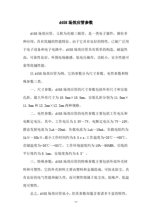
d458场效应管参数
d458场效应管参数
d458场效应管,又称为有源三极管,是一类电子器件,拥有多种应用,具有优越的性能特征。
由于它具有良好的特性,已被广泛用于电子设备和电子电路中。
d458场效应管具有简单的构造,耐温性高,可靠性良好,外围电场敏感,低电压操作,功耗小,安全性能可靠等优越性能。
以d458场效应管为例,它的参数分为尺寸参数、电性参数和特殊参数三类。
一、尺寸参数:d458场效应管的尺寸参数包括外形尺寸和安装孔距,最大外形尺寸为10.5mm×10.5mm,安装孔距分别为11.8mm×
11.8mm和12.2mm×12.2mm两种规格。
二、电性参数:d458场效应管的电性参数主要包括工作电压和电断定电压,其中,工作电压为3.5V~7V,电断定电压为7V~10V,静态发射电流为2uA~20mA,负载电流为1uA~10mA,负载电阻约为1kΩ~50kΩ,最小工作时间约为0.5μs,工作温度为-20℃~+80℃,存储温度为-30℃~+85℃,工作环境湿度约为10%~95%RH,引线的平行度约为0.1mm,安装度角约为0.3°。
三、特殊参数:d458场效应管的特殊参数主要包括外部外壳材料和可塑性,它的外壳材料主要由塑料和金属组成,可防水防尘,具有良好的电气性能和耐久性,而可塑性则属于低尘埃、低噪声、低温度可塑性。
总之,d458场效应管虽小,但其参数却蕴含着诸多丰富的特性,
其参数可以满足用户在各种不同场合下的需求,在应用中发挥十分重要的作用。
无论是电子产品的维修还是制作,d458场效应管的参数都将给用户带来良好的使用体验。
INTORQ_BA_BFK458说明书

E型
N型
双弹力制动器
INTORQ | BA 14.0168 | 02/2016
3
产品序列号
INTORQ B
FK
-
产品组:制动器
产品族:弹簧加压式制动器
型号:458
机座号:06、08、10、12、14、16、18、20、25
结构形式: E - 可调 (可用调节环降低制动力矩) N - 不可调 L - 不可调,长寿命型
据所需的配置进行组装。标贴内容,尤其是包装标贴、型号铭牌和类型代 码,是与一套定子总成相对应的。 ❚ 以单独组件供应时,会没有上述标识。
INTORQ | BA 14.0168 | 02/2016
4
目录
1 一般说明 ........................................................................ 7 1.1 使用说明书概要 ..............................................................7 1.2 采用规范 ....................................................................7 1.3 安全须知 ....................................................................8 1.4 采用概念 ....................................................................9 1.5 采用缩写 ....................................................................9
AOD412中文资料
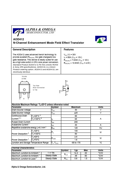
SymbolTyp Max 14.2203950R θJL 0.8 1.5Maximum Junction-to-AmbientASteady-State °C/W Maximum Junction-to-LeadCSteady-State°C/WThermal Characteristics ParameterUnits Maximum Junction-to-Ambient At ≤ 10s R θJA °C/W AOD412AOD412SymbolMin TypMaxUnits BV DSS 30V 0.0051T J =55°C5I GSS 100nA V GS(th) 1.5 2.152.5V I D(ON)85A 5.57T J =125°C8.8118.2510.5m Ωg FS 60S V SD 0.721V I S85A C iss 13201600pF C oss 533pF C rss 154pF R g0.95 1.2ΩQ g (10V)2632nC Q g (4.5V)13.316.2nC Q gs 3.2nC Q gd 6.6nC t D(on)7.210ns t r 12.518ns t D(off)2233ns t f 69ns t rr 29.736ns Q rr2936nCTHIS PRODUCT HAS BEEN DESIGNED AND QUALIFIED FOR THE CONSUMER MARKET. APPLICATIONS OR USES AS CRITICAL COMPONENTS IN LIFE SUPPORT DEVICES OR SYSTEMS ARE NOT AUTHORIZED. AOS DOES NOT ASSUME ANY LIABILITY ARISING OUT OF SUCH APPLICATIONS OR USES OF ITS PRODUCTS. AOS RESERVES THE RIGHT TO IMPROVE PRODUCT DESIGN,FUNCTIONS AND RELIABILITY WITHOUT NOTICE.Gate Drain Charge V GS =0V, V DS =15V, f=1MHz SWITCHING PARAMETERS Total Gate Charge Gate Source Charge Gate resistanceV GS =0V, V DS =0V, f=1MHzV GS =4.5V, V DS =15V, I D =20ATotal Gate Charge Turn-On Rise Time Turn-Off DelayTime V GS =10V, V DS =15V, R L =0.75Ω, R GEN =3ΩTurn-Off Fall TimeTurn-On DelayTime m ΩV GS =4.5V, I D =20AI S =1A,V GS =0V V DS =5V, I D =20AMaximum Body-Diode Continuous CurrentInput Capacitance Output Capacitance DYNAMIC PARAMETERS R DS(ON)Static Drain-Source On-ResistanceForward TransconductanceDiode Forward VoltageI DSS µA Gate Threshold Voltage V DS =V GS I D =250µA V DS =24V, V GS =0VV DS =0V, V GS = ±20V Zero Gate Voltage Drain Current Gate-Body leakage current Electrical Characteristics (T J =25°C unless otherwise noted)STATIC PARAMETERS Parameter Conditions Body Diode Reverse Recovery Time Body Diode Reverse Recovery ChargeI F =20A, dI/dt=100A/µsDrain-Source Breakdown Voltage On state drain currentI D =250µA, V GS =0V V GS =10V, V DS =5V V GS =10V, I D =20AReverse Transfer Capacitance I F =20A, dI/dt=100A/µs A: The value of R θJA is measured with the device mounted on 1in 2 FR-4 board with 2oz. Copper, in a still air environment with T A =25°C. The Power dissipation P DSM is based on steady-state R θJA and the maximum allowed junction temperature of 150°C. The value in any given application depends on the user's specific board design, and the maximum temperature fo 175°C may be used if the PCB or heatsink allows it.B. The power dissipation P D is based on T J(MAX)=175°C, using junction-to-case thermal resistance, and is more useful in setting the upper dissipation limit for cases where additional heatsinking is used. It is used to determine the current rating, when this rating falls below the package limit.C: Repetitive rating, pulse width limited by junction temperature T J(MAX)=175°C.D. The R θJA is the sum of the thermal impedence from junction to case R θJC and case to ambient.E. The static characteristics in Figures 1 to 6 are obtained using <300 µs pulses, duty cycle 0.5% max.F. These tests are performed with the device mounted on 1 in 2 FR-4 board with 2oz. Copper, in a still air environment with T A =25°C. The SOA curve provides a single pulse rating.G. The maximum current rating is limited by the package current capability. Rev 3 : July 2005AOD412AOD412AOD412。
AOD438中文资料

SymbolTyp Max 14.2203950R θJC 0.8 1.5Maximum Junction-to-AmbientASteady-State °C/W Maximum Junction-to-CaseCSteady-State°C/WThermal Characteristics ParameterUnits Maximum Junction-to-Ambient At ≤ 10s R θJA °C/W AOD438AOD438SymbolMin TypMaxUnits BV DSS 30V 1T J =55°C5I GSS 100nA V GS(th)1 1.83V I D(ON)85A 2.8 3.5T J =125°C4.45.54.4 5.5m Ωg FS 106S V SD 0.721V I S85A C iss 32003840pF C oss 590pF C rss 414pF R g0.540.7ΩQ g (10V)6376nC Q g (4.5V)3340nC Q gs 8.6nC Q gd 17.6nC t D(on)12ns t r 15.5ns t D(off)40ns t f 14ns t rr 3441ns Q rr30nCTHIS PRODUCT HAS BEEN DESIGNED AND QUALIFIED FOR THE CONSUMER MARKET. APPLICATIONS OR USES AS CRITICAL COMPONENTS IN LIFE SUPPORT DEVICES OR SYSTEMS ARE NOT AUTHORIZED. AOS DOES NOT ASSUME ANY LIABILITY ARISING OUT OF SUCH APPLICATIONS OR USES OF ITS PRODUCTS. AOS RESERVES THE RIGHT TO IMPROVE PRODUCT DESIGN,FUNCTIONS AND RELIABILITY WITHOUT NOTICE.Gate Drain Charge V GS =0V, V DS =15V, f=1MHz SWITCHING PARAMETERS Total Gate Charge Gate Source Charge Gate resistanceV GS =0V, V DS =0V, f=1MHzV GS =4.5V, V DS =15V, I D =20ATotal Gate Charge Turn-On Rise Time Turn-Off DelayTime V GS =10V, V DS =15V, R L =0.75Ω, R GEN =3ΩTurn-Off Fall TimeTurn-On DelayTime m ΩV GS =4.5V, I D =20AI S =1A,V GS =0VV DS =5V, I D =20AMaximum Body-Diode Continuous CurrentInput Capacitance Output CapacitanceDYNAMIC PARAMETERS R DS(ON)Static Drain-Source On-ResistanceForward TransconductanceDiode Forward Voltage I DSS µA Gate Threshold Voltage V DS =V GS I D =250µA V DS =24V, V GS =0VV DS =0V, V GS = ±20V Zero Gate Voltage Drain Current Gate-Body leakage current Electrical Characteristics (T J =25°C unless otherwise noted)STATIC PARAMETERS Parameter Conditions Body Diode Reverse Recovery TimeBody Diode Reverse Recovery Charge I F =20A, dI/dt=100A/µsDrain-Source Breakdown Voltage On state drain currentI D =250µA, V GS =0V V GS =10V, V DS =5V V GS =10V, I D =20AReverse Transfer Capacitance I F =20A, dI/dt=100A/µsA: The value of R θJA is measured with the device mounted on 1in 2 FR-4 board with 2oz. Copper, in a still air environment with T A =25°C. The Power dissipation P DSM is based on steady-state R θJA and the maximum allowed junction temperature of 150°C. The value in any givenapplication depends on the user's specific board design, and the maximum temperature of 175°C may be used if the PCB or heatsink allows it.B. The power dissipation P D is based on T J(MAX)=175°C, using junction-to-case thermal resistance, and is more useful in setting the upperdissipation limit for cases where additional heatsinking is used. It is used to determine the current rating, when this rating falls below the package limit.C: Repetitive rating, pulse width limited by junction temperature T J(MAX)=175°C.D. The R θJA is the sum of the thermal impedence from junction to case R θJC and case to ambient.E. The static characteristics in Figures 1 to 6 are obtained using <300 µs pulses, duty cycle 0.5% max.F. These tests are performed with the device mounted on 1 in 2 FR-4 board with 2oz. Copper, in a still air environment with T A =25°C. The SOA curve provides a single pulse rating.G. The maximum current rating is limited by the package current capability. Rev 2: July 2005AOD438AOD438AOD438。
FMMT458中文资料
- (Volts)
1.2 1.0 0.8 0.6
V
0.4 0.2 0 0.001 0.01 0.1 1 10 20
V
0.4 0.2 0 0.001 0.01 0.1 1 10 20
I+ - Collector Current (Amps)
- (Volts)
I+ - Collector Current (Amps)
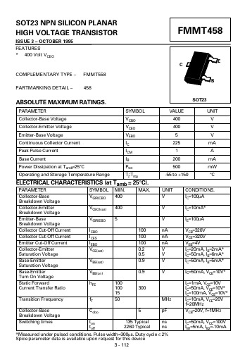
SOT23 NPN SILICON PLANAR HIGH VOLTAGE TRANSISTOR
ISSUE 3 OCTOBER 1995 FEATURES * 400 Volt VCEO
FMMT458
E
C COMPLEMENTARY TYPE PARTMARKING DETAIL FMMT558 B 458 SOT23 SYMBOL VCBO VCEO VEBO IC ICM IB Ptot Tj:Tstg MIN. 400 400 5 100 100 100 0.2 0.5 0.9 0.9 100 100 15 50 300 MHz 5 135 Typical 2260 Typical pF ns ns MAX. VALUE 400 400 5 225 1 200 500 -55 to +150 UNIT V V V nA nA nA V V V V UNIT V V V mA A mA mW °C
1.6 1.4
-55°C +25°C +100°C +175°C
VCE =10V
I - Collector Current (Amps)
- (Volts)
1.2 1.0 0.8 0.6 0.4 0.2 0 0.001 0.01 0.1 1 10 20
MC-458CB641ES-A10中文资料

©1999Document No. M14015EJ4V0DS00 (4th edition)Date Published February 2000 NS CP(K)Printed in JapanDATA SHEETThe mark • shows major revised points.The information in this document is subject to change without notice. Before using this document, please confirm that this is the latest version.Not all devices/types available in every country. Please check with local NEC representative for availability and additional information.DescriptionThe MC-458CB641ES and MC-458CB641PS are 8,388,608 words by 64 bits synchronous dynamic RAM module (Small Outline DIMM) on which 4 pieces of 128M SDRAM: µPD45128163 are assembled.These modules provide high density and large quantities of memory in a small space without utilizing the surface-mounting technology on the printed circuit board.Decoupling capacitors are mounted on power supply line for noise reduction.Features• 8,388,608 words by 64 bits organization • Clock frequency and access time from CLKPart number/CAS latency Clock frequency (MAX.)Access time from CLK (MAX.)MC-458CB641ES-A80CL = 3125 MHz 6 ns CL = 2100 MHz 6 ns MC-458CB641ES-A10CL = 3100 MHz 6 ns CL = 277 MHz 7 ns MC-458CB641PS-A80CL = 3125 MHz 6 ns CL = 2100 MHz 6 ns MC-458CB641PS-A10CL = 3100 MHz 6 ns CL = 277 MHz7 ns• Fully Synchronous Dynamic RAM, with all signals referenced to a positive clock edge • Pulsed interface• Possible to assert random column address in every cycle • Quad internal banks controlled by BA0, BA1 (Bank Select)• Programmable burst-length: 1, 2, 4, 8 and Full Page • Programmable wrap sequence (Sequential / Interleave)• Programmable /CAS latency (2, 3)• Automatic precharge and controlled precharge • CBR (Auto) refresh and self refresh • Single 3.3 V ±0.3 V power supply • LVTTL compatible • 4,096 refresh cycles/64 ms• Burst termination by Burst Stop command and Precharge command • 144-pin small outline dual in-line memory module (Pin pitch = 0.8 mm)• Unbuffered type • Serial PD55Data Sheet M14015EJ4V0DS002Ordering InformationPart numberClock frequency MHz (MAX.)PackageMounted devicesMC-458CB641ES-A80125 MHz 144-pin Small Outline DIMM (Socket Type)4 pieces of µPD45128163G5 (Rev. E)(10.16mm (400) TSOP (II))MC-458CB641ES-A10100 MHz Edge connector: Gold plated 25.4 mm heightMC-458CB641PS-A80125 MHz 4 pieces of µPD45128163G5 (Rev. P)(10.16mm (400) TSOP (II))MC-458CB641PS-A10100 MHz55Data Sheet M14015EJ4V0DS003Pin Configuration144-pin Dual In-line Memory Module Socket Type (Edge connector: Gold plated)Vss DQ 0DQ 1DQ 2DQ 3DQ 4DQ 5DQ 6DQ 7Vss DQMB0DQMB1A0A1A2Vss DQ 8DQ 9DQ 10DQ 11DQ 12DQ 13DQ 14DQ 15Vss NC NCCLK0Vcc /RAS /WE /CS0NC NC Vss NC NC DQ 16DQ 17DQ 18DQ 19Vss DQ 20DQ 21DQ 22DQ 23Vcc A6A8Vss A9A10Vcc DQMB2DQMB3Vss DQ 24DQ 25DQ 26DQ 27DQ 28DQ 29DQ 30DQ 31Vss SDAVss DQ 32DQ 33DQ 34DQ 35Vcc DQ 36DQ 37DQ 38DQ 39Vss DQMB4DQMB5Vcc A3A4A5Vss DQ 40DQ 41DQ 42DQ 43Vcc DQ 44DQ 45DQ 46DQ 47Vss NC NCCKE0Vcc/CASNCNCNCCLK1VssNCNCVccDQ 48DQ 49DQ 50DQ 51VssDQ 52DQ 53DQ 54DQ 55VccA7BA0 (A13)VssBA1 (A12)A11VccDQMB6DQMB7VssDQ 56DQ 57DQ 58DQ 59VccDQ 60DQ 61DQ 62DQ 63Vss SCL Vcc CC V CC V CC V CC V CC V CC V /xxx indicates active low signal.A0 - A11:Address Inputs[Row: A0 - A11, Column: A0 - A8]BA0(A13),BA1(A12):SDRAM Bank Select DQ0 - DQ63:Data Inputs/Outputs CLK0, CLK1:Clock Input CKE0:Clock Enable Input /CS0:Chip Select Input /RAS :Row Address Strobe /CAS :Column Address Strobe /WE :Write Enable DQMB0 - DQMB7:DQ Mask EnableSDA :Serial Data I/O for PD SCL :Clock Input for PD V CC :Power Supply V SS :Ground NC:No ConnectionData Sheet M14015EJ4V0DS004Block Diagram/WE /CS0A0 - A11A0 - A11 : D0 - D3DQMB0DQMB1DQMB2DQMB3/RAS/RAS : D0 - D3/CAS /CAS : D0 - D3CKE0CKE : D0 - D3BA0A13 : D0 - D3BA1A12 : D0 - D3Remarks 1.D0 - D3: µPD45128163 (2M words x 16 bits x 4 banks)2.The value of all resistors is 10 Ω.Electrical Specifications• All voltages are referenced to V SS (GND).• After power up, wait more than 100 µs and then, execute power on sequence and CBR (Auto) refresh before proper device operation is achieved.Absolute Maximum RatingsParameter Symbol Condition Rating Unit Voltage on power supply pin relative to GND V CC–0.5 to +4.6V Voltage on input pin relative to GND V T–0.5 to +4.6V Short circuit output current I O50mA Power dissipation P D4W Operating ambient temperature T A0 to +70°C Storage temperature T stg–55 to +125°C Caution Exposing the device to stress above those listed in Absolute Maximum Ratings could cause permanent damage. The device is not meant to be operated under conditions outside the limitsdescribed in the operational section of this specification. Exposure to Absolute Maximum Ratingconditions for extended periods may affect device reliability.Recommended Operating ConditionsParameter Symbol Condition MIN.TYP.MAX.Unit Supply voltage V CC 3.0 3.3 3.6V High level input voltage V IH 2.0V CC +0.3V Low level input voltage V IL–0.3+0.8V Operating ambient temperature T A070°CCapacitance (T A = 25°C, f = 1 MHz)Parameter Symbol Test condition MIN.TYP.MAX.Unit1530pF Input capacitance C I1A0 - A11, BA0(A13), BA1(A12),/RAS, /CAS, /WEC I2CLK02337C I3CKE01526C I4/CS01526C I5DQMB0 - DQMB7510Data input/output capacitance C I/O DQ0 - DQ63512pFData Sheet M14015EJ4V0DS005Data Sheet M14015EJ4V0DS006ParameterSymbol Test conditionMIN.MAX.Unit Notes Operating currentI CC1Burst length = 1, t RC ≥ t RC(MIN.)/CAS latency = 2-A80440mA1-A10440/CAS latency = 3-A80440-A10440Precharge standby current inI CC2P CKE ≤ V IL(MAX.), t CK = 15 ns 4mA power down modeI CC2PS CKE ≤ V IL(MAX.), t CK = ∞4Precharge standby current in non power down modeI CC2NCKE ≥ V IH(MIN.), t CK = 15 ns, /CS ≥ V IH(MIN.),Input signals are changed one time during 30 ns.80mA I CC2NSCKE ≥ V IH(MIN.), t CK = ∞, Input signals are stable.32Active standby current in I CC3P CKE ≤ V IL(MAX.), t CK = 15 ns 20mApower down mode I CC3PS CKE ≤ V IL(MAX.), t CK = ∞16Active standby current in non power down modeI CC3NCKE ≥ V IH(MIN.), t CK = 15 ns, /CS ≥ V IH(MIN.),Input signals are changed one time during 30 ns.120mA I CC3NSCKE ≥ V IH(MIN.), t CK = ∞, Input signals are stable.80Operating current I CC4t CK ≥ t CK(MIN.), I O = 0 mA/CAS latency = 2-A80580mA2(Burst mode)-A10440/CAS latency = 3-A80700-A10560CBR (Auto) refresh current I CC5t RC ≥ t RC(MIN.)/CAS latency = 2-A80920mA3-A10920/CAS latency = 3-A80920-A10920Self refresh current I CC6CKE ≤ 0.2 V8mA Input leakage current I I(L)V I = 0 to 3.6 V, All other pins not under test = 0 V – 4+4µA Output leakage current I O(L)D OUT is disabled, V O = 0 to 3.6 V –1.5+1.5µA High level output voltage V OH I O = – 4.0 mA 2.4V Low level output voltageV OLI O = + 4.0 mA0.4VNotes 1.I CC1 depends on output loading and cycle rates. Specified values are obtained with the output open. Inaddition to this, I CC1 is measured on condition that addresses are changed only one time during t CK(MIN.).2.I CC4 depends on output loading and cycle rates. Specified values are obtained with the output open. Inaddition to this, I CC4 is measured on condition that addresses are changed only one time during t CK(MIN.).3.I CC5 is measured on condition that addresses are changed only one time during t CK(MIN.).555Test ConditionsParameter Value Unit AC high level input voltage / low level input voltage 2.4 / 0.4V Input timing measurement reference level 1.4VTransition time (Input rise and fall time)1nsOutput timing measurement reference level 1.4V2.4 V1.4 V0.4 VCLK2.4 V1.4 V0.4 VInputOutput5Data Sheet M14015EJ4V0DS007Data Sheet M14015EJ4V0DS008MIN.MAX.MIN.MAX.Clock cycle time/CAS latency = 3t CK38(125 MHz)10(100 MHz)ns /CAS latency = 2t CK210(100 MHz)13(77 MHz)ns Access time from CLK/CAS latency = 3t AC366ns 1/CAS latency = 2t AC267ns 1CLK high level width t CH 33ns CLK low level width t CL33ns Data-out hold time/CAS latency = 3t OH333ns 1/CAS latency = 2t OH233ns 1Data-out low-impedance time t LZ00nsData-out high-impedance time/CAS latency = 3t HZ33636ns /CAS latency = 2t HZ23637ns Data-in setup time t DS 22ns Data-in hold time t DH 11ns Address setup time t AS 22ns Address hold time t AH 11ns CKE setup time t CKS 22ns CKE hold timet CKH 11ns CKE setup time (Power down exit)t CKSP 22ns Command (/CS0, /RAS, /CAS, /WE,DQMB0 - DQMB7) setup time t CMS 22ns Command (/CS0, /RAS, /CAS, /WE,DQMB0 - DQMB7) hold timet CMH11nsNote 1. Output loadOutput50 pFRemark These specifications are applied to the monolithic device.MIN.MAX.MIN.MAX.ACT to REF/ACT command period(Operation)t RC7070nsREF to REF/ACT command period(Refresh)t RC17078nsACT to PRE command period t RAS48120,00050120,000nsPRE to ACT command period t RP2020nsDelay time ACT to READ/WRITE command t RCD2020nsACT(one) to ACT(another) command period t RRD1620nsData-in to PRE command period/CAS latency = 3t DPL3810ns/CAS latency = 2t DPL2810nsData-in to ACT(REF) command/CAS latency = 3t DAL31CLK+201CLK+20nsperiod (Auto precharge)/CAS latency = 2t DAL21CLK+201CLK+20nsMode register set cycle time t RSC22CLKTransition time t T0.530130nsRefresh time (4,096 refresh cycles)t REF6464msData Sheet M14015EJ4V0DS009Serial PD(1/2) Byte No.Function Described Hex Bit 7Bit 6Bit 5Bit 4Bit 3Bit 2Bit 1Bit 0Notes80H10000000128 bytes 0Defines the number of bytes written intoserial PD memory1Total number of bytes of serial PD memory08H00001000256 bytes 2Fundamental memory type04H00000100SDRAM 3Number of rows0CH0000110012 rows 4Number of columns09H000010019 columns 5Number of banks01H00000001 1 bank 6Data width40H010******* bits 7Data width (continued)00H0000000008Voltage interface01H00000001LVTTL 9CL = 3 Cycle time-A8080H100000008 ns-A10A0H1010000010 ns 10CL =3 Access time-A8060H01100000 6 ns-A1060H01100000 6 ns 11DIMM configuration type00H00000000None 12Refresh rate/type80H10000000Normal 13SDRAM width10H00010000×16 14Error checking SDRAM width00H00000000None 15Minimum clock delay01H00000001 1 clock 16Burst length supported8FH100011111, 2, 4, 8, F 17Number of banks on each SDRAM04H00000100 4 banks 18/CAS latency supported06H000001102, 3 19/CS latency supported01H00000001020/WE latency supported01H00000001021SDRAM module attributes00H0000000022SDRAM device attributes : General0EH0000111023CL = 2 Cycle time-A80A0H1010000010 ns-A10D0H1101000013 ns 24CL = 2 Access time-A8060H01100000 6 ns-A1070H011100007 ns 25-2600H0000000027t RP(MIN.)-A8014H0001010020 ns-A1014H0001010020 ns 28t RRD(MIN.)-A8010H0001000016 ns-A1014H0001010020 ns 29t RCD(MIN.)-A8014H0001010020 ns-A1014H0001010020 ns 30t RAS(MIN.)-A8030H0011000048 ns-A1032H0011001050 ns 31Module bank density10H0001000064M bytes10Data Sheet M14015EJ4V0DS00(2/2) Byte No.Function Described Hex Bit 7Bit 6Bit 5Bit 4Bit 3Bit 2Bit 1Bit 0Notes 32Command and address-A8020H00100000 2 ns signal setup time-A1020H00100000 2 ns 33Command and address-A8010H00010000 1 ns signal hold time-A1010H00010000 1 ns 34Data signal input setup time-A8020H00100000 2 ns-A1020H00100000 2 ns 35Data signal input hold time-A8010H00010000 1 ns-A1010H00010000 1 ns 36-6100H0000000062SPD revision-A8012H00010010 1.2 A-A1012H00010010 1.2 A 63Checksum for bytes 0 - 62-A80E7H11100111-A104DH01001101 64-71Manufacture’s JEDEC ID code72Manufacturing location73-90Manufacture’s P/N91-92Revision code93-94Manufacturing date95-98Assembly serial number99-126Mfg specific126Intel specification frequency-A8064H01100100100 MHz-A1064H01100100100 MHz 127Intel specification /CAS-A8087H10000111 latency support-A1085H10000101Timing ChartRefer to the SYNCHRONOUS DRAM MODULE TIMING CHART Information (M13348E).Data Sheet M14015EJ4V0DS0011Data Sheet M14015EJ4V0DS0012Package Drawing144-PIN DUAL IN-LINE MODULE (SOCKET TYPE)X 2.55 MIN.M144S-80A15Y2.0 MIN.5Data Sheet M14015EJ4V0DS001314Data Sheet M14015EJ4V0DS00Data Sheet M14015EJ4V0DS0015CAUTION FOR HANDLING MEMORY MODULESWhen handling or inserting memory modules, be sure not to touch any components on the modules, such as the memory IC, chip capacitors and chip resistors. It is necessary to avoid undue mechanical stress on these components to prevent damaging them.When re-packing memory modules, be sure the modules are NOT touching each other. Modules in contact with other modules may cause excessive mechanical stress, which may damage the modules.• The information in this document is subject to change without notice. Before using this document, please confirm that this is the latest version.• No part of this document may be copied or reproduced in any form or by any means without the prior written consent of NEC Corporation. NEC Corporation assumes no responsibility for any errors which may appear in this document.• NEC Corporation does not assume any liability for infringement of patents, copyrights or other intellectual propertyrights of third parties by or arising from use of a device described herein or any other liability arising from useof such device. No license, either express, implied or otherwise, is granted under any patents, copyrights or other intellectual property rights of NEC Corporation or others.• Descriptions of circuits, software, and other related information in this document are provided for illustrative purposes in semiconductor product operation and application examples. The incorporation of these circuits,software, and information in the design of the customer's equipment shall be done under the full responsibilityof the customer. NEC Corporation assumes no responsibility for any losses incurred by the customer or third parties arising from the use of these circuits, software, and information.• While NEC Corporation has been making continuous effort to enhance the reliability of its semiconductor devices, the possibility of defects cannot be eliminated entirely. To minimize risks of damage or injury to persons orproperty arising from a defect in an NEC semiconductor device, customers must incorporate sufficient safety measures in its design, such as redundancy, fire-containment, and anti-failure features.• NEC devices are classified into the following three quality grades:"Standard", "Special", and "Specific". The Specific quality grade applies only to devices developed based on a customer designated "quality assurance program" for a specific application. The recommended applications ofa device depend on its quality grade, as indicated below. Customers must check the quality grade of each device before using it in a particular application.Standard: Computers, office equipment, communications equipment, test and measurement equipment, audio and visual equipment, home electronic appliances, machine tools, personal electronic equipment and industrial robotsSpecial: Transportation equipment (automobiles, trains, ships, etc.), traffic control systems, anti-disastersystems, anti-crime systems, safety equipment and medical equipment (not specifically designed for life support)Specific: Aircraft, aerospace equipment, submersible repeaters, nuclear reactor control systems, life support systems or medical equipment for life support, etc.The quality grade of NEC devices is "Standard" unless otherwise specified in NEC's Data Sheets or Data Books. If customers intend to use NEC devices for applications other than those specified for Standard quality grade, they should contact an NEC sales representative in advance.M7 98. 8。
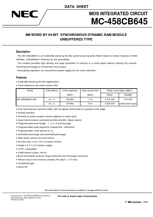
MC-458CB645资料
The information in this document is subject to change without notice.©1998DATA SHEETThe mark • shows major revised points.Document No. M13297EJ2V0DS00 (2nd edition)Date Published May 1998 NS CP (K)Printed in JapanDescriptionThe MC-458CB645 is an 8,388,608 words by 64 bits synchronous dynamic RAM module on which 8 pieces of 64M SDRAM : µPD4564841 (Revision E) are assembled.This module provides high density and large quantities of memory in a small space without utilizing the surface-mounting technology on the printed circuit board.Decoupling capacitors are mounted on power supply line for noise reduction.Features• 8,388,608 words by 64 bits organization • Clock frequency and clock access timeFamily/CAS latencyClock frequencyClock access timePower consumption (MAX.)(MAX.)(MAX.)Active Standby MC-458CB645-A10BCL = 3100 MHz 7 ns 3,312 mW 14.4 mW CL = 267 MHz8 ns3,024 mW(CMOS level input)• Fully Synchronous Dynamic RAM, with all signals referenced to a positive clock edge • Pulsed interface• Possible to assert random column address in every cycle • Quad internal banks controlled by BA0 and BA1 (Bank Select)• Programmable burst-length : 1, 2, 4, 8 and full page • Programmable wrap sequence (Sequential / Interleave)• Programmable /CAS latency (2, 3)• Automatic precharge and controlled precharge • CBR (Auto) refresh and self refresh • All DQs have 10 Ω ±10 % of series resistor • Single 3.3 V ± 0.3 V power supply • LVTTL compatible• 4,096 refresh cycles / 64 ms• Burst termination by Burst Stop command and Precharge command • 168-pin dual in-line memory module (Pin pitch = 1.27 mm)• Unbuffered type • Serial PD2Ordering InformationPart numberClock frequency(MAX.)PackageMounted devicesMC-458CB645FA-A10B100 MHz168-pin Dual In-line Memory Module (Socket Type)Edge connector (Gold plated)31.75 mm (1.25 inch) height8 pieces of µPD4564841G5 (Revision E)(400 mil TSOP (II))[Single side]3Pin Configuration168-pin Dual In-line Memory Module Socket Type (Edge connector: Gold plated)V SS DQ32DQ33DQ34DQ35Vcc DQ36DQ37DQ38DQ39DQ40V SS DQ41DQ42DQ43DQ44DQ45Vcc NC V SS NC NC Vcc /CAS DQMB4DQMB5NC /RAS V SS A1A3A5A7A9BA0 (A13)A11Vcc CLK1NC V SS CKE0NCDQMB6DQMB7NC Vcc NC NC NC NC V SS DQ48DQ49DQ50DQ51Vcc DQ52NC NC NC V SS DQ53DQ54DQ55V SS DQ56DQ57DQ58DQ59Vcc DQ60DQ61DQ62DQ63V SS NC NC SA0SA1SA2VccV SS DQ0DQ1DQ2DQ3Vcc DQ4DQ5DQ6DQ7DQ8V SS DQ9DQ10DQ11DQ12DQ13Vcc DQ14DQ15NC NC V SS NC NC Vcc /WE DQMB0DQMB1/CS0NC V SS A0A2A4A6A8A10BA1 (A12)Vcc Vcc CLK0V SS NC /CS2DQMB2DQMB3NC Vcc NC NC NC NC V SS DQ16DQ17DQ18DQ19Vcc DQ20NC NC NC V SS DQ21DQ22DQ23V SS DQ24DQ25DQ26DQ27Vcc DQ28DQ29DQ30DQ31V SS NC NC NC SDA SCL VccA0 - A11:Address Inputs[Row : A0 - A11, Column : A0 - A8]BA0 (A13),BA1 (A12):SDRAM Bank Select DQ0 - DQ63:Data Inputs / Outputs CLK0, CLK1:Clock Input CKE0:Clock Enable Input /CS0, /CS2:Chip Select Input /RAS :Row Address Strobe /CAS :Column Address Strobe /WE :Write EnableDQMB0 - DQMB7:DQ Mask EnableSA0 - SA2:Address Input for EEPROM SDA :Serial Data I/O for PD SCL :Clock Input for PD V CC :Power Supply V SS :Ground NC: No Connection/XXX indicates active low signal.4Block DiagramA0 - A11A0 - A11: D0 - D7SCLSDASA0SA1SA2A13: D0 - D7/RAS /RAS: D0 - D7/CAS: D0 - D7CKE0CKE: D0 - D7CLK0CLK1V CCD0 - D7D0 - D7V SSBA1A12: D0 - D7Remarks 1.The value of all resistors is 10 Ω.2.D0 - D7 : µPD4564841 (Revision E)(2M words × 8 bits × 4 banks)5Electrical Specifications• All voltages are referenced to V SS (GND).• After power up, wait more than 100 µs and then, execute power on sequence and auto refresh before proper device operation is achieved.Absolute Maximum RatingsParameterSymbol ConditionRating Unit Voltage on power supply pin relative to GND V CC –0.5 to +4.6V Voltage on input pin relative to GND V T –0.5 to +4.6V Short circuit output current I O 50mA Power dissipationP D 8W Operating ambient temperature T A 0 to +70°C Storage temperatureT stg–55 to +125°CCaution Exposing the device to stress above those listed in Absolute Maximum Ratings could cause permanent damage. The device is not meant to be operated under conditions outside the limits described in the operational section of this specification. Exposure to Absolute Maximum Rating conditions for extended periods may affect device reliability.Recommended Operating ConditionsParameterSymbol ConditionMIN.TYP.MAX.Unit Supply voltage V CC 3.0 3.33.6V High level input voltage V IH 2.0V CC +0.3V Low level input voltage V IL −0.3+0.8V Operating ambient temperatureT A70°CCapacitance (T A = 25 °C, f = 1 MHz)ParameterSymbol Test conditionMIN.TYP.MAX.Unit Input capacitanceC I1A0 - A11, BA0 (A13), BA1 (A12), /RAS,/CAS, /WE47pFC I2CLK0, CLK138C I3CKE047C I4/CS0, /CS226C I5DQMB0 - DQMB711Data input / output capacitance C I/ODQ0 - DQ6313pF••Parameter Symbol Test condition MIN.MAX.Unit Notes Operating current I CC1Burst length = 1,/CAS latency= 2520mA1t RC≥t RC (MIN.), I O = 0mA/CAS latency= 3600Precharge standby current in I CC2P CKE ≤ V IL (MAX.), t CK = 15ns8mApower down mode I CC2PS CKE ≤ V IL (MAX.), t CK = ∞4Precharge standby current in I CC2N CKE ≥V IH (MIN.), t CK = 15ns, /CS≥V IH (MIN.),160mAnon power down mode Input signals are changed one time during 30ns.I CC2NS CKE ≥V IH (MIN.), t CK = ∞,48Input signals are stable.Active standby current in I CC3P CKE ≤ V IL (MAX.), t CK = 15ns40mApower down mode I CC3PS CKE ≤ V IL (MAX.), t CK = ∞32Active standby current in I CC3N CKE ≥V IH (MIN.), t CK = 15ns, /CS ≥V IH (MIN.),200mAnon power down mode Input signals are changed one time during 30ns.I CC3NS CKE ≥V IH (MIN.), t CK = ∞,80Input signals are stable.Operating current I CC4t CK≥t CK (MIN.), I O = 0mA/CAS latency = 2560mA2 (Burst mode)/CAS latency = 3840Refresh current I CC5t RC≥t RC (MIN.)/CAS latency = 2840mA3/CAS latency = 3920Self refresh current I CC6t RC = 100 ns, t CK (MIN.)8mAInput leakage current I I (L)V I = 0 to 3.6V,All other pins not under test = 0 V–8+8µAOutput leakage current I O (L)D OUT is disabled, V O = 0 to 3.6V–1.5+1.5µAHigh level output voltage V OH I O = –4.0mA 2.4VLow level output voltage V OL I O = +4.0mA0.4VNotes 1.I CC1 depends on output loading and cycle rates. Specified values are obtained with the output open. In addition to this, I CC1 is measured on condition that addresses are changed only one time during t CK (MIN.).2.I CC4 depends on output loading and cycle rates. Specified values are obtained with the output open. Inaddition to this, I CC4 is measured on condition that addresses are changed only one time during t CK (MIN.).3.I CC5 is measured on condition that addresses are changed only one time during t CK (MIN.).6AC Characteristics Test Conditions•AC measurements assume t T =1ns.•Reference level for measuring timing of input signals is 1.4V. Transition times are measured between V IH and V IL.•If t T is longer than 1ns, reference level for measuring timing of input signals is V IH (MIN.) and V IL (MAX.).•An access time is measured at 1.4V.2.0 VCLK1.4 V0.8 V2.0 VInput1.4 V0.8 VOutput78ParameterSymbol-A10BUnitNoteMIN.MAX.Clock cycle time/CAS latency = 3t CK310(100 MHz)ns /CAS latency = 2t CK215(67 MHz)ns Access time from CLK/CAS latency = 3t AC37ns 1/CAS latency = 2t AC28ns 1CLK high level width t CH 3.5ns CLK low level width t CL 3.5ns Data-out hold timet OH 3ns 1Data-out low-impedance timet LZ 0ns Data-out high-impedance time /CAS latency = 3t HZ337ns /CAS latency = 2t HZ238ns Data-in setup time t DS 2.5ns Data-in hold time t DH 1ns Address setup time t AS 2.5ns Address hold time t AH 1ns CKE setup time t CKS 2.5ns CKE hold timet CKH 1ns CKE setup time (Power down exit)t CKSP 2.5ns Command (/CS0, /CS2, /RAS, /CAS, /WE,DQMB0 - DQMB7) setup timet CMS2.5nsCommand (/CS0, /CS2, /RAS, /CAS, /WE,DQMB0 - DQMB7) hold timet CMH1nsNote 1. Output loadOutput50 pF50 ΩRemark These specifications are applied to the monolithic device.Parameter Symbol-A10B Unit NoteMIN.MAX.REF to REF/ACT command period t RC90nsACT to PRE command period t RAS60120,000nsPRE to ACT command period t RP30nsDelay time ACT to READ/WRITE command t RCD30nsACT (0) to ACT (1) command period t RRD20nsData-in to PRE command period t DPL10nsData-in to ACT (REF) command/CAS latency = 3t DAL31CLK + 30nsperiod (Auto precharge)/CAS latency = 2t DAL21CLK + 30nsMode register set cycle time t RSC2CLKTransition time t T130nsRefresh time t REF64ms910Serial PD(1/2)Byte No.Function DescribedHex Bit 7Bit 6Bit 5Bit 4Bit 3Bit 2Bit 1Bit 0Notes 0Defines the number of bytes written into serial PD memory80H1128 bytes1Total number of bytes of serial PD memory08H1256 bytes2Fundamental memory type 04H 00000100SDRAM 3Number of rows 0CH 0000110012 rows4Number of columns 09H 000010019 columns5Number of banks 01H 00000001 1 bank 6Data width40H 010******* bits 7Data width (continued)00H 0000000008Voltage interface 01H 00000001LVTTL 9CL = 3 cycle time A0H 1010000010 ns 10CL = 3 access time 70H 011100007 ns 11DIMM configuration type 00H 00000000Non-parity 12Refresh rate / type 80H 10000000Normal 13SDRAM width08H 00001000×814Error checking SDRAM width 00H 00000000None 15Minimum clock delay 01H 00000001 1 clock 16Burst length supported8FH 100011111, 2, 4, 8, F 17Number of banks on each SDRAM 04H 00000100 4 banks 18/CAS latency supported 06H 000001102, 319/CS latency supported 01H 00000001020/WE latency supported 01H 00000001021SDRAM module attributes 00H 0000000022SDRAM device attributes : General 0EH 0000111023CL = 2 cycle time F0H 1111000015 ns 24CL = 2 access time80H 100000008 ns 25-2600H 0000000027t RP (MIN.)1EH 0001111030 ns 28t RRD (MIN.)14H 0001010020 ns 29t RCD (MIN.)1EH 0001111030 ns 30t RAS (MIN.)3CH 0011110060 ns 31Module bank density10H164M bytes(2/2) Byte No.Function Described Hex Bit 7Bit 6Bit 5Bit 4Bit 3Bit 2Bit 1Bit 0Notes32-6100H0000000062SPD revision01H00000001163Checksum for bytes 0 - 6232H0011001064-71Manufacture’s JEDEC ID code72Manufacturing location73-90Manufacture’s P/N91-92Revision code93-94Manufacturing date95-98Assembly serial number99-125Mfg specific126Intel specification frequency66H0110011066 MHz 127Intel specification /CAS latency support06H000001102, 3Timing ChartPlease refer to NEC Synchronous DRAM Data sheet.1112Package Drawings168 PIN DUAL IN-LINE MODULE (SOCKET TYPE)M168S-50A90Z3.0 MIN.0.118 MIN.A1133.35±0.13 5.250±0.006B 11.430.450C 36.83 1.450D 6.350.250D1 2.00.079D2 3.1250.123E 54.61 2.150G 6.350.250H 1.27 (T.P.)0.050 (T.P.)I 8.890.350J 24.4950.964K 42.18 1.661L 17.780.700M 31.75±0.13 1.250±0.006M111.970.471M219.780.779N 4.00 MAX.0.158 MAX.P 1.00.039Q R 2.0R 0.079R 4.00±0.100.157+0.005−0.004S T 1.27±0.10.050±0.004U 4.00 MIN.0.157 MIN.V 0.25 MAX.0.010 MAX.W 1.0±0.050.039+0.003−0.002X 2.54±0.100.100±0.004Y 3.0 MIN.0.118 MIN.3.0φ0.118φ•131415[MEMO]CAUTION FOR HANDLING MEMORY MODULESWhen handling or inserting memory modules, be sure not to touch any components on the modules, such as the memory IC, chip capacitors and chip resistors. It is necessary to avoid undue mechanical stress on these components to prevent damaging them.When re-packing memory modules, be sure the modules are NOT touching each other. Modules in contact with other modules may cause excessive mechanical stress, which may damage the modules.No part of this document may be copied or reproduced in any form or by any means without the prior written consent of NEC Corporation. NEC Corporation assumes no responsibility for any errors which may appear in this document.NEC Corporation does not assume any liability for infringement of patents, copyrights or other intellectual property rights of third parties by or arising from use of a device described herein or any other liability arising from use of such device. No license, either express, implied or otherwise, is granted under any patents, copyrights or other intellectual property rights of NEC Corporation or others.While NEC Corporation has been making continuous effort to enhance the reliability of its semiconductor devices, the possibility of defects cannot be eliminated entirely. To minimize risks of damage or injury to persons or property arising from a defect in an NEC semiconductor device, customers must incorporate sufficient safety measures in its design, such as redundancy, fire-containment, and anti-failure features.NEC devices are classified into the following three quality grades:"Standard", "Special", and "Specific". The Specific quality grade applies only to devices developed based ona customer designated "quality assurance program" for a specific application. The recommended applicationsof a device depend on its quality grade, as indicated below. Customers must check the quality grade of each device before using it in a particular application.Standard: Computers, office equipment, communications equipment, test and measurement equipment, audio and visual equipment, home electronic appliances, machine tools, personal electronicequipment and industrial robotsSpecial: Transportation equipment (automobiles, trains, ships, etc.), traffic control systems, anti-disaster systems, anti-crime systems, safety equipment and medical equipment (not specifically designedfor life support)Specific: Aircrafts, aerospace equipment, submersible repeaters, nuclear reactor control systems, life support systems or medical equipment for life support, etc.The quality grade of NEC devices is "Standard" unless otherwise specified in NEC's Data Sheets or Data Books.If customers intend to use NEC devices for applications other than those specified for Standard quality grade, they should contact an NEC sales representative in advance.Anti-radioactive design is not implemented in this product.M4 96. 5。
AOD448中文资料
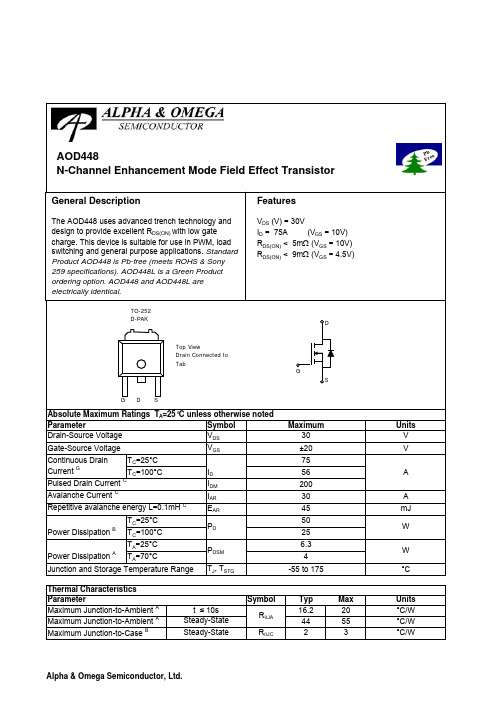
SymbolTyp Max 16.2204455R θJC 23Maximum Junction-to-Case BSteady-State°C/WThermal Characteristics ParameterUnits Maximum Junction-to-Ambient A t ≤ 10s R θJA °C/W Maximum Junction-to-Ambient A Steady-State °C/WAOD448SymbolMin TypMaxUnits BV DSS 30V 0.0251T J =55°C5I GSS 100nA V GS(th)1 1.52.5V I D(ON)100A 4.15T J =125°C5679m Ωg FS 40S V SD 1V I S55A C iss 23422810pF C oss 462pF C rss 320pF R g1.1 1.5ΩQ g (10V)7084nC Q g (4.5V)34.842nC Q gs 13.1nC Q gd 18.5nC t D(on)9ns t r 11ns t D(off)30.7ns t f 9.2ns t rr 34.542ns Q rr28.334nCTHIS PRODUCT HAS BEEN DESIGNED AND QUALIFIED FOR THE CONSUMER MARKET. APPLICATIONS OR USES AS CRITICAL COMPONENTS IN LIFE SUPPORT DEVICES OR SYSTEMS ARE NOT AUTHORIZED. AOS DOES NOT ASSUME ANY LIABILITY ARISING OUT OF SUCH APPLICATIONS OR USES OF ITS PRODUCTS. AOS RESERVES THE RIGHT TO IMPROVE PRODUCT DESIGN,FUNCTIONS AND RELIABILITY WITHOUT NOTICE.Body Diode Reverse Recovery TimeDrain-Source Breakdown Voltage On state drain currentI D =250µA, V GS =0V V GS =10V, V DS =5V V GS =10V, I D =30AReverse Transfer Capacitance I F =20A, dI/dt=100A/µsV GS =0V, V DS =15V, f=1MHz SWITCHING PARAMETERS Electrical Characteristics (T J =25°C unless otherwise noted)STATIC PARAMETERS ParameterConditions I DSS µA Gate Threshold Voltage V DS =V GS , I D =250µA V DS =24V, V GS =0VV DS =0V, V GS =±20V Zero Gate Voltage Drain Current Gate-Body leakage current Forward TransconductanceDiode Forward Voltage R DS(ON)Static Drain-Source On-Resistancem ΩI S =1A, V GS =0V V DS =5V, I D =20AV GS =4.5V, I D =20AGate resistanceV GS =0V, V DS =0V, f=1MHzTurn-Off Fall TimeTotal Gate Charge V GS =10V, V DS =15V, I D =20AGate Source Charge Gate Drain Charge Total Gate Charge Body Diode Reverse Recovery Charge I F =20A, dI/dt=100A/µsMaximum Body-Diode Continuous CurrentInput Capacitance Output Capacitance Turn-On DelayTime DYNAMIC PARAMETERS Turn-On Rise Time Turn-Off DelayTime V GS =10V, V DS =15V, R L =0.75Ω, R GEN =3ΩA: The value of R θJA is measured with the device mounted on 1in 2 FR-4 board with 2oz. Copper, in a still air environment with T A =25°C. ThePower dissipation P DSM is based on R θJA and the maximum allowed junction temperature of 150°C. The value in any given application depends on the user's specific board design, and the maximum temperature of 175°C may be used if the PCB allows it.B. The power dissipation P D is based on T J(MAX)=175°C, using junction-to-case thermal resistance, and is more useful in setting the upper dissipation limit for cases where additional heatsinking is used.C: Repetitive rating, pulse width limited by junction temperature T J(MAX)=175°C.D. The R θJA is the sum of the thermal impedence from junction to case R θJC and case to ambient.E. The static characteristics in Figures 1 to 6 are obtained using <300 µs pulses, duty cycle 0.5% max.F. These curves are based on the junction-to-case thermal impedence which is measured with the device mounted to a large heatsink, assuming a maximum junction temperature of T J(MAX)=175°C.G. The maximum current rating is limited by bond-wires.H. These tests are performed with the device mounted on 1 in 2 FR-4 board with 2oz. Copper, in a still air environment with T A =25°C. The SOA curve provides a single pulse rating. I. Revision 0: June 2005AOD448AOD448AOD448。
AOD规程
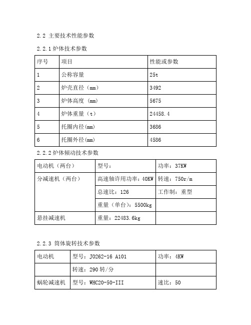
2.2 主要技术性能参数2.2.1炉体技术参数2.2.2炉体倾动技术参数2.2.3 筒体旋转技术参数2.2.4 氧枪升降传动机构技术参数2.2.5氧枪旋转传动机构技术参数3 AOD炉使用规程3.1 开动前检查3.1.1 维修人员每天进行的检查3.1.1.1 各润滑点润滑是否良好3.1.1.2 冷却水管及水冷部件有无损坏和渗水3.1.1.3 各传动部件是否正常,有无妨碍运行的杂物3.1.1.4 紧固零件有无松动3.1.1.5 配气系统有无明显漏气现象3.1.1.6 各隔离开关是否处于正常位置3.1.1.7 各线路、电器、盘等有无异状3.1.1.8 变频器是否处于正常状态3.1.1.9 PLC有无报警情况3.1.2 电炉操作工应进行的检查3.1.2.1 检查电脑显示的数据是否正常3.1.2.2 排尘是否启动,排尘罩是否开到工作位置3.1.2.3 旋转筒体是否转到工作位置3.1.2.4 冷却循环水是否良好3.2 开动程序3.2.1 加钢水、吹氧程序3.2.1.1 开动排尘罩到工作位置,启动排尘3.2.1.2 转动筒体到工作位置3.2.1.3 关闭在线烘烤器,转动炉体向北倾斜45°左右3.2.1.4 将钢包中的钢水倒入AOD炉中3.2.1.5 将炉体转到工作位置后,开始吹氧、冶炼3.2.2 出钢程序3.2.2.1 开动操作台车后退3.2.2.2 将钢包缓缓下降,同时旋转炉体,3.2.3 运行中注意事项4 AOD炉维护规程4.1 维护保养4.1.1 操作工对设备应做好如下维护工作4.1.1.1 清扫设备及操作室,配气室4.1.1.2 注意倾听电机和减速机有无异常声音4.1.1.3 仔细观察水冷系统是否畅通,有无渗漏4.1.1.4 清理设备运转部位的杂物4.1.2 维修人员对设备应做好如下维护工作4.1.2.1 及时检查和紧固各部螺栓4.1.2.2 检查处理跑、冒、滴、漏4.1.2.3 检查各传动部分,添加润滑油4.2 润滑4.2.1 设备润滑应到位4.2.1.1 按规定周期注油和换油4.2.1.2 润滑油必须清洁无杂质4.2.1.3 注油前,应将油孔边缘的污物擦干净4.2.1.4 换油时必须先用洗油将油箱彻底清洗干净,再用清洁布擦干,方可注入新油4.2.1.5 注入的油量应以有关规定和标尺刻度为准4.2.1.6 AOD各部润滑部位及周期4.3 维护标准4.3.1 AOD维护应达到下列标准4.3.1.1 设备本体及周围清洁、整齐、无跑、冒、滴、漏现象4.3.1.2 设备润滑装置保持齐全完好4.3.1.3 设备各部紧固,调整良好,基础螺栓及各部螺栓、销子等齐全4.3.1.4 安全防护装置及各种仪表维护保管好,完整齐全,准确可靠4.3.1.5 按规定事项正确填写记录5 AOD检修5.1 检修的类别、周期和内容5.1.1 检修的类别和周期5.1.2 小修工作内容5.1.2.1清扫各部位的灰尘和油污5.1.2.2 检查各类阀门、配气系统、润滑系统、氧枪跑、冒、滴、漏情况,更换填料、密封圈。
AOD450中文资料

SymbolTyp Max 17.1305060R θJC 46Maximum Junction-to-Case BSteady-State°C/WThermal Characteristics ParameterUnits Maximum Junction-to-Ambient A t ≤ 10s R θJA °C/W Maximum Junction-to-Ambient A Steady-State °C/W AOD450AOD450SymbolMin TypMaxUnits BV DSS 200V 1T J =55°C5I GSS 100nA V GS(th)356V I D(ON)10A 0.550.70T J =125°C1.1 1.32g FS 8.7S V SD 0.81V I S6A C iss 215pF C oss 32pF C rss 7.2pF R g5.5ΩQ g (10V) 3.82nC Q g (4.5V)0.92nC Q gs 1.42nC Q gd 1.47nC t D(on) 6.3ns t r 3.3ns t D(off)10.5ns t f 2.8ns t rr 59ns Q rr142nCTHIS PRODUCT HAS BEEN DESIGNED AND QUALIFIED FOR THE CONSUMER MARKET. APPLICATIONS OR USES AS CRITICAL COMPONENTS IN LIFE SUPPORT DEVICES OR SYSTEMS ARE NOT AUTHORIZED. AOS DOES NOT ASSUME ANY LIABILITY ARISING OUT OF SUCH APPLICATIONS OR USES OF ITS PRODUCTS. AOS RESERVES THE RIGHT TO IMPROVE PRODUCT DESIGN,FUNCTIONS AND RELIABILITY WITHOUT NOTICE.Body Diode Reverse Recovery TimeDrain-Source Breakdown Voltage On state drain currentI D =10mA, V GS =0V V GS =10V, V DS =15V V GS =10V, I D =3.8AReverse Transfer Capacitance I F =3.8A, dI/dt=100A/µsV GS =0V, V DS =25V, f=1MHz SWITCHING PARAMETERS Electrical Characteristics (T J =25°C unless otherwise noted)STATIC PARAMETERS ParameterConditions I DSS µA Gate Threshold Voltage V DS =V GS , I D =250µA V DS =160V, V GS =0VV DS =0V, V GS =±30V Zero Gate Voltage Drain Current Gate-Body leakage current Forward TransconductanceDiode Forward VoltageStatic Drain-Source On-Resistance R DS(ON)ΩI S =1A, V GS =0V V DS =15V, I D =3.8AGate resistanceV GS =0V, V DS =0V, f=1MHzTurn-Off Fall TimeTotal Gate Charge V GS =10V, V DS =25V, I D =3.8AGate Source Charge Gate Drain Charge Total Gate Charge Body Diode Reverse Recovery Charge I F =3.8A, dI/dt=100A/µsMaximum Body-Diode Continuous CurrentGInput Capacitance Output Capacitance Turn-On DelayTime DYNAMIC PARAMETERS Turn-On Rise Time Turn-Off DelayTime V GS =10V, V DS =25V, R L =6.5Ω, R GEN =3ΩA: The value of R θJA is measured with the device mounted on 1in 2 FR-4 board with 2oz. Copper, in a still air environment with T A =25°C. The Power dissipation P DSM is based on R θJA and the maximum allowed junction temperature of 150°C. The value in any a given application depends on the user's specific board design, and the maximum temperature fo 175°C may be used if the PCB allows it.B. The power dissipation P D is based on T J(MAX)=175°C, using junction-to-case thermal resistance, and is more useful in setting the upper dissipation limit for cases where additional heatsinking is used.C: Repetitive rating, pulse width limited by junction temperature T J(MAX)=175°C.D. The R θJA is the sum of the thermal impedence from junction to case R θJC and case to ambient.E. The static characteristics in Figures 1 to 6 are obtained using <300 µs pulses, duty cycle 0.5% max.F. These curves are based on the junction-to-case thermal impedence which is measured with the device mounted to a large heatsink, assuming a maximum junction temperature of T J(MAX)=175°C.G. The maximum current rating is limited by bond-wires.H. These tests are performed with the device mounted on 1 in 2 FR-4 board with 2oz. Copper, in a still air environment with T A =25°C. The SOA curve provides a single pulse rating. Rev0: Feb 2006AOD450AOD450AOD450。
AOD414中文资料
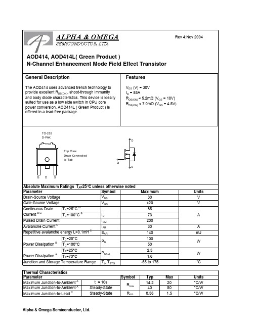
SymbolTyp Max 14.2204050R θJL 0.56 1.5°C/W Maximum Junction-to-Ambient ASteady-State Maximum Junction-to-Lead CSteady-State°C/WThermal Characteristics ParameterUnits Maximum Junction-to-Ambient At ≤ 10s R θJA °C/WSymbolMin TypMaxUnits BV DSS 30V 0.0051T J =55°C5I GSS 100nA V GS(th) 1.2 1.82.4V I D(ON)110A 4.2 5.2T J =125°C67.55.67m Ωg FS 85S V SD 0.71V I S85A C iss 60607000pF C oss 638pF C rss 355pF R g0.450.6ΩQ g (10V)96.4115nC Q g (4.5V)46.455nC Q gs 13.6nC Q gd 15.6nC t D(on)15.721ns t r 14.221ns t D(off)55.575ns t f 1421ns t rr 3138ns Q rr2429nCT C =100°C T A =25°C-55 to 175THIS PRODUCT HAS BEEN DESIGNED AND QUALIFIED FOR THE CONSUMER MARKET. APPLICATIONS OR USES AS CRITICAL COMPONENTS IN LIFE SUPPORT DEVICES OR SYSTEMS ARE NOT AUTHORIZED. AOS DOES NOT ASSUME ANY LIABILITY ARISING OUT OF SUCH APPLICATIONS OR USES OF ITS PRODUCTS. AOS RESERVES THE RIGHT TO IMPROVE PRODUCT DESIGN,FUNCTIONS AND RELIABILITY WITHOUT NOTICE.Gate Drain Charge V GS =0V, V DS =15V, f=1MHz SWITCHING PARAMETERS Total Gate Charge Gate Source Charge Gate resistanceV GS =0V, V DS =0V, f=1MHzTotal Gate Charge V GS =4.5V, V DS =15V, I D =20ATurn-On Rise Time Turn-Off DelayTime V GS =10V, V DS =15V, R L =0.75Ω, R GEN =3ΩTurn-Off Fall TimeTurn-On DelayTime m ΩV GS =4.5V, I D =20AI S =1A,V GS =0V V DS =5V, I D =20AMaximum Body-Diode Continuous CurrentInput Capacitance Output Capacitance DYNAMIC PARAMETERS R DS(ON)Static Drain-Source On-ResistanceForward TransconductanceDiode Forward VoltageI DSS µA Gate Threshold Voltage V DS =V GS I D =250µA V DS =24V, V GS =0VV DS =0V, V GS = ±20V Zero Gate Voltage Drain Current Gate-Body leakage current Electrical Characteristics (T J =25°C unless otherwise noted)STATIC PARAMETERS Parameter Conditions Body Diode Reverse Recovery Time Body Diode Reverse Recovery ChargeI F =20A, dI/dt=100A/µsDrain-Source Breakdown Voltage On state drain currentI D =250µA, V GS =0V V GS =4.5V, V DS =5V V GS =10V, I D =20AReverse Transfer Capacitance I F =20A, dI/dt=100A/µs A: The value of R θJA is measured with the device mounted on 1in 2 FR-4 board with 2oz. Copper, in a still air environment with T A =25°C. The Power dissipation P DSM is based on steady-state R θJA and the maximum allowed junction temperature of 150°C. The value in any a given application depends on the user's specific board design, and the maximum temperature fo 175°C may be used if the PCB or heatsink allows it.B. The power dissipation P D is based on T J(MAX)=175°C, using junction-to-case thermal resistance, and is more useful in setting the upper dissipation limit for cases where additional heatsinking is used. It is used to determine the current rating, when this rating falls below the package limit.C: Repetitive rating, pulse width limited by junction temperature T J(MAX)=175°C.D. The R θJA is the sum of the thermal impedence from junction to case R θJC and case to ambient.E. The static characteristics in Figures 1 to 6 are obtained using <300 µs pulses, duty cycle 0.5% max.F. These tests are performed with the device mounted on 1 in 2 FR-4 board with 2oz. Copper, in a still air environment with T A =25°C. The SOA curve provides a single pulse rating.G. The maximum current rating is limited by the package current capability.。
458系列电磁炉维修手1

2.16散热系统
将IGBT及整流器DB紧贴于散热片上,利用风扇运转通过电磁炉进、出风口形成的气流将散热片上的热及线盘L1等零件工作时产生的热、加热锅具辐射进电磁炉内的热排出电磁炉外。
注解:由于中国大陆目前并未提出电磁炉须作强制性电磁兼容(EMC)认证,基于成本原因,内销产品大部分没有将CY1、CY2装上,L1用跳线取代,但基本上不影响电磁炉使用性能。
2.18辅助电源
AC220V 50/60Hz电压接入变压器初级线圈,次级两绕组分别产生13.5V和23V交流电压。
13.5V交流电压由D3~D6组成的桥式整流电路整流、C37滤波,在C37上获得的直流电压VCC除供给散热风扇使用外,还经由IC1三端稳压IC稳压、C38滤波,产生+5V电压供控制电路使用。
(2)当IGBT结温由于某原因(例如散热系统故障)而高于95℃时,加热立即停止,并报知信息(祥见故障代码表)。
(3)当热敏电阻TH开路或短路时,发出不启动指令,并报知相关的信息(祥见故障代码表)。
(4)关机时如IGBT温度>50℃,CPU发出风扇继续运转指令,直至温度<50℃(继续运转超过4分钟如温度仍>50℃,风扇停转;风扇延时运转期间,按1次关机键,可关闭风扇)。
(1)配合VAC检测电路、电流检测电路反馈的信息,判别是否己放入适合的锅具,作出相应的动作指令(祥见加热开关控制及试探过程一节)。
(2)根据VCE取样电压值,自动调整PWM脉宽,抑制VCE脉冲幅度不高于1100V(此值适用于耐压1200V的IGBT,耐压1500V的IGBT抑制值为1300V)。
458系列电磁炉说明

458系列电磁炉详细说明电磁灶是一种利用电磁感应原理将电能转换为热能的厨房电器。
在电磁灶内部,由整流电路将50/60Hz的交流电压变成直流电压,再通过操纵电路将直流电压转换成频率为20-40kHz的高频电压,高速转变的电流流过线圈会产生高速转变的磁场,当磁场内的磁力线通过金属器皿(导磁又导电材料)底部,金属体内产生无数的小涡流,使器皿本身自行高速发烧,然后再加热器皿内的东西。
一、458系列简介458系列是由建安电子技术开发制造厂设计开发的新一代电磁炉,界面有LED发光二极管显示模式、LED数码显示模式、LCD液晶显示模式、VFD莹光显示模式机种。
操作功能有加热火力调剂、自动恒温设定、按时关机、预约开/关机、预置操作模式、自动泡茶、自动烧饭、自动煲粥、自动煲汤及煎、炸、烤、暖锅等料理功能机种。
额定加热功率有700~3000W 的不同机种,功率调剂范围为额定功率的85%,而且在全电压范围内功率自动恒定。
200~240V 机种电压利用范围为160~260V,100~120V机种电压利用范围为90~135V。
全系列机种均适用于50/60Hz的电压频率。
利用环境温度为-23℃~45℃。
电控功能有锅具超温爱惜、锅具干烧爱惜、锅具传感器开/短路爱惜、2小时不按键(忘记关机)爱惜、IGBT温度限制、IGBT温度太高爱惜、低温环境工作模式、IGBT测温传感器开/短路爱惜、高低电压爱惜、浪涌电压爱惜、VCE抑制、VCE太高爱惜、过零检测、小物检测、锅具材质检测。
458系列虽然机种较多,且功能复杂,但不同的机种其主控电路原理一样,区别只是零件参数的不同及CPU程序不同而己。
电路的各项测控要紧由一块8位4K内存的单片机组成,外围线路简单且零件极少,并设有故障报警功能,故电路靠得住性高,维修容易,维修时依照故障报警指示,对应检修相关单元电路,大部份都可轻易解决。
二、原理分析特殊零件简介LM339集成电路LM339内置四个翻转电压为6mV的电压比较器,当电压比较器输入端电压正向时(+输入端电压高于-输入端电压),置于LM339内部操纵输出端的三极管截止,现在输出端相当于开路;当电压比较器输入端电压反向时(-输入端电压高于+输入端电压),置于LM339内部操纵输出端的三极管导通,将比较器外部接入输出端的电压拉低,现在输出端为0V。
AOD413A中文资料
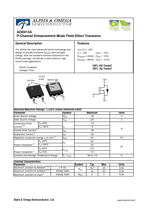
A: The value of RθJA is measured with the device in a still air environment with T A =25° C. The power dissipation P DSM and current rating IDSM are based on TJ(MAX)=150° C, using t ≤ 10s junction-to-ambient thermal resistance. B. The power dissipation PD is based on TJ(MAX)=175° C, using junction-to-case thermal resistance, and is more useful in setting the upper dissipation limit for cases where additional heatsinking is used. C: Repetitive rating, pulse width limited by junction temperature TJ(MAX)=175° C. D. The RθJA is the sum of the thermal impedence from junction to case RθJC and case to ambient. -20 E. The static characteristics in Figures 1 to 6 are obtained using <300 µs pulses, duty cycle 0.5% max. 20 F. These curves are based on the junction-to-case thermal impedence which is measured with the device mounted to a large heatsink, assuming C. The SOA curve provides a single pulse ratin g. a maximum junction temperature of TJ(MAX)=175° G. These tests are performed with the device mounted on 1 in2 FR-4 board with 2oz. Copper, in a still air environment with TA=25° C. H. The maximum current rating is limited by bond-wires. *This device is guaranteed green after data code 8X11 (Sep 1ST 2008). Rev1: Oct 2008 COMPONENTS IN LIFE SUPPORT DEVICES OR SYSTEMS ARE NOT AUTHORIZED. AOS DOES NOT ASSUME ANY LIABILITY ARISING OUT OF SUCH APPLICATIONS OR USES OF ITS PRODUCTS. AOS RESERVES THE RIGHT TO IMPROVE PRODUCT DESIGN, FUNCTIONS AND RELIABILITY WITHOUT NOTICE.
AOD452A中文资料
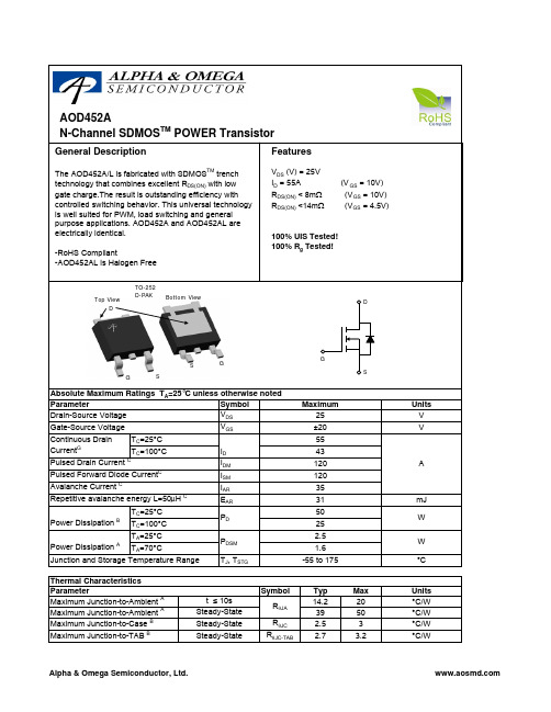
Thermal Characteristics Parameter Maximum Junction-to-Ambient A Maximum Junction-to-Ambient A Maximum Junction-to-Case B
Maximum Junction-to-TAB B
W °C
Units °C/W °C/W °C/W °C/W
元器件交易网
AOD452A
Electrical Characteristics (TJ=25°C unless otherwise noted)
Symbol
Parameter
Conditions
17
1.4
5
2
1.2
10
VGS=4.5V
1
ID=20A
0.8
0 25 50 75 100 125 150 1075 200
Temperature (°C)
18
Figure 4: On-Resistance vs. Junction Temperature
RDS(ON) (mΩ)
30
ID=30A 25
Min Typ Max Units
STATIC PARAMETERS
BVDSS Drain-Source Breakdown Voltage
ID=250uA, VGS=0V
25
V
IDSS
Zero Gate Voltage Drain Current
VDS=25V, VGS=0V
TJ=55°C
10 µA
COMPONENTS IN LIFE SUPPORT DEVICES OR SYSTEMS ARE NOT AUTHORIZED. AOS DOES NOT ASSUME ANY LIABILITY ARISING OUT OF SUCH APPLICATIONS OR USES OF ITS PRODUCTS. AOS RESERVES THE RIGHT TO IMPROVE PRODUCT DESIGN, FUNCTIONS AND RELIABILITY WITHOUT NOTICE.
uc3845中文资料应用
uc3845中文资料应用
时间:2015-04-15 21:12 来源:电工之家作者:编辑部
双列8脚直插式或14脚贴片塑料封装。
是高性能固定频率电流型控制器。
它们是专门设计用于脱线工作和直流一直流变换器应用的,为使用者提供了一种低成本、高效率外接元件最少的解决方案。
这些集成电路包括振荡器、温度补偿参考源、高增益误差放大器、电流检测比较器及一个适合于驱动 MOS功率场效应晶体管(PFET)的理想的高电流图腾柱输出。
芯片还包括一系列保护特性,如具有滞后特性的输入和参考电压欠压锁定保护功能,逐个周期的限流保护,用于测量单个脉冲的锁存器和一个每隔一个振荡周期封闭脉冲输出的触发器——这就使得输出占空比可以在50%~70%范围内可调。
具有16 V(开启)和10 V(关闭)的欠压输出锁定(UVLO)门限值。
特别适用于脱线工作变换器。
uCX845是为低电压应用特别制造的,它具有8.5 V(开启)和7.6 V(关闭)欠压输出锁定门限值。
其特点为
(1)电流模式工作,输出开关频率为500 kHz。
(2)输出占空比可从50%~70%调节。
(3)自动前馈补偿。
(4)逐个周期的限流保护,锁定式脉冲宽度调制(PWM)。
(5)有欠压锁定的内部调整参考源。
(6)高电流图腾柱式输出。
(7)带滞后的输入欠压锁定。
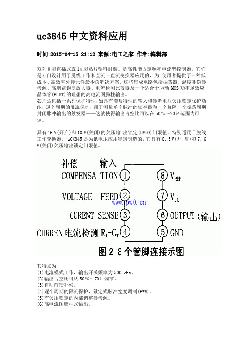
封装引脚图:
【互换兼容】
CS3845 CW3845 KA3885脚同(FA13845N)FA13845P L3845 LM3845 ST3845UC UC3845W UC3845N脚同UC3845A。
AOD458
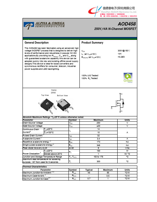
Symbol R θJA R θCS R θJCMaximum Junction-to-Ambient A,G-55MaximumThermal CharacteristicsUnits °C/W 45ParameterTypical Absolute Maximum Ratings T A =25°C unless otherwise notedMaximum Case-to-sink AMaximum Junction-to-CaseD,F°C/W°C/W 0.70.51GS DGSDSymbolMin Typ Max Units250300BV DSS /∆TJ 0.27V/ oC 110I GSS Gate-Body leakage current ±100n ΑV GS(th)Gate Threshold Voltage33.84.5V R DS(ON)0.220.28Ωg FS 10S V SD 0.741V I S Maximum Body-Diode Continuous Current 14A I SM32A C iss 505637770pF C oss 70104140pF C rss 37.112pF R g1.32.63.9ΩQ g 91215nC Q gs 3.8nC Q gd 4.6nC t D(on)21ns t r 58ns t D(off)29ns t f 33ns t rr 120150180ns Q rr11.241.5µCTHIS PRODUCT HAS BEEN DESIGNED AND QUALIFIED FOR THE CONSUMER MARKET. APPLICATIONS OR USES AS CRITICAL COMPONENTS IN LIFE SUPPORT DEVICES OR SYSTEMS ARE NOT AUTHORIZED. AOS DOES NOT ASSUME ANY LIABILITY ARISING OUT OF SUCH APPLICATIONS OR USES OF ITS PRODUCTS. AOS RESERVES THE RIGHT TO IMPROVE PRODUCT DESIGN,FUNCTIONS AND RELIABILITY WITHOUT NOTICE.Body Diode Reverse Recovery Charge I F =14A,dI/dt=100A/µs,V DS =100VMaximum Body-Diode Pulsed CurrentInput Capacitance Output Capacitance Turn-On DelayTime Turn-Off DelayTime V GS =0V, V DS =0V, f=1MHzTurn-Off Fall TimeTotal Gate Charge V GS =10V, V DS =200V, I D =14AGate Source Charge Gate Drain Charge I S =1A,V GS =0VV DS =40V, I D =7A V DS =0V, V GS =±30V V GS =10V, I D =7A I D =250µA, V GS =0V, T J =25°C I D =250µA, V GS =0V, T J =150°C V DS =5V, I D =250µA V DS =200V, T J =125°C Zero Gate Voltage Drain Current ID=250µA, VGS=0V I DSS Zero Gate Voltage Drain Current V DS =250V, V GS =0V I F =14A,dI/dt=100A/µs,V DS =100VV GS =0V, V DS =25V, f=1MHz SWITCHING PARAMETERS Electrical Characteristics (T J =25°C unless otherwise noted)STATIC PARAMETERS Parameter Conditions BV DSS µA V Drain-Source Breakdown Voltage Body Diode Reverse Recovery TimeStatic Drain-Source On-Resistance DYNAMIC PARAMETERS Turn-On Rise Time Forward Transconductance V GS =10V, V DS =125V, I D =14A, R G =25ΩGate resistanceDiode Forward VoltageReverse Transfer Capacitance A. The value of R θJA is measured with the device in a still air environment with T A =25°C.B. The power dissipation P D is based on T J(MAX)=175°C in a TO252 package, using junction-to-case thermal resistance, and is more useful in setting the upper dissipation limit for cases where additional heatsinking is used.C. Repetitive rating, pulse width limited by junction temperature T J(MAX)=175°C.D. The R θJA is the sum of the thermal impedance from junction to case R θJC and case to ambient.E. The static characteristics in Figures 1 to 6 are obtained using <300 µs pulses, duty cycle 0.5% max.F. These curves are based on the junction-to-case thermal impedance which is measured with the device mounted to a large heatsink, assuming a maximum junction temperature of T J(MAX)=175°C.G.These tests are performed with the device mounted on 1 in 2 FR-4 board with 2oz. Copper, in a still air environment with T A =25°C.H. L=60mH, I AS =3.4A, V DD =150V, R G =10Ω, Starting T J =25°CTYPICAL ELECTRICAL AND THERMAL CHARACTERISTICSVdsC ha rgeGate Charge Test Circuit & W av eformResistiv e Switching Test Circuit & W av eformsVddVdsI dVgsB V I Unclamped Inductive Switching (UIS) Test Circuit & W av eformsARDSS2E = 1/2 LI V ddARAR。
ul458标准中文版
ul458标准中文版
UL 458标准(Underwriters Laboratories 458标准)的中文版是《UL 458标准:便携式电源设备和逆变器使用标准》。
该标
准规定了便携式电源设备和逆变器的要求和测试方法,包括设备的安全性、可靠性和性能等方面的要求。
该标准适用于一些便携式电源设备和逆变器,如充电器、逆变器、电动工具和便携式电池等。
标准涵盖了这些设备的电气安全性、电磁兼容性、辐射排放、抗抖动和抗震动性能等方面。
UL 458标准的中文版提供了制造商和测试实验室使用的指导,以确保产品符合安全和性能标准,并为消费者提供可靠、安全的使用体验。
对于销售到美国和加拿大市场的设备,符合该标准通常是获得UL认证的前提条件之一。
这是一份重要的标准文件,制定了便携式电源设备和逆变器的基本要求,对保证产品的质量和安全性至关重要。
- 1、下载文档前请自行甄别文档内容的完整性,平台不提供额外的编辑、内容补充、找答案等附加服务。
- 2、"仅部分预览"的文档,不可在线预览部分如存在完整性等问题,可反馈申请退款(可完整预览的文档不适用该条件!)。
- 3、如文档侵犯您的权益,请联系客服反馈,我们会尽快为您处理(人工客服工作时间:9:00-18:30)。
Symbol
Typ Max 15204455R θJC 1.83t ≤ 10s R θJA °C/W Maximum Junction-to-Ambient A Steady-State °C/W Maximum Junction-to-Case B
Steady-State
°C/W
Thermal Characteristics Parameter
Units Maximum Junction-to-Ambient A AOD458
AOD458
Symbol
Min Typ
Max
Units BV DSS 30
V 0.002
1T J =55°C
5I GSS 100nA V GS(th)1 1.7
3
V I D(ON)100
A
3.24T J =125°C
563.85
g FS 107S V SD 0.72
1V I S
50
A C iss 5750
7500pF C oss 640pF C rss 370pF R g
0.41ΩQ g (4.5V)41
nC Q gs 18nC Q gd 10nC t D(on)13.5
19ns t r 1420ns t D(off)5880ns t f 13.519ns t rr 3955ns Q rr
39
nC THIS PRODUCT HAS BEEN DESIGNED AND QUALIFIED FOR THE CONSUMER MARKET. APPLICATIONS OR USES AS CRITICAL COMPONENTS IN LIFE SUPPORT DEVICES OR SYSTEMS ARE NOT AUTHORIZED. AOS DOES NOT ASSUME ANY LIABILITY ARISING OUT OF SUCH APPLICATIONS OR USES OF ITS PRODUCTS. AOS RESERVES THE RIGHT TO IMPROVE PRODUCT DESIGN,FUNCTIONS AND RELIABILITY WITHOUT NOTICE.
Body Diode Reverse Recovery Charge I F =20A, dI/dt=100A/µs
Maximum Body-Diode Continuous Current
Input Capacitance Output Capacitance Turn-On DelayTime DYNAMIC PARAMETERS Turn-On Rise Time Turn-Off DelayTime V GS =10V, V DS =15V, R L =0.75Ω, R GEN =3Ω
Gate resistance
V GS =0V, V DS =0V, f=1MHz
Turn-Off Fall Time
V GS =4.5V, V DS =15V, ID=20A
Gate Source Charge Gate Drain Charge Total Gate Charge m Ω
Forward Transconductance
Diode Forward Voltage Static Drain-Source On-Resistance
I S =1A, V GS =0V V DS =5V, I D =20A
V GS =4.5V, I D =20A
R DS(ON)
I DSS µA Gate Threshold Voltage V DS =V GS , I D =250µA V DS =24V, V GS =0V
V DS =0V, V GS =±12V Zero Gate Voltage Drain Current Gate-Body leakage current Electrical Characteristics (T J =25°C unless otherwise noted)STATIC PARAMETERS Parameter
Conditions Body Diode Reverse Recovery Time
Drain-Source Breakdown Voltage On state drain current
I D =250uA, V GS =0V V GS =10V, V DS =5V V GS =10V, I D =20A
Reverse Transfer Capacitance I F =20A, dI/dt=100A/µs
V GS =0V, V DS =15V, f=1MHz SWITCHING PARAMETERS A: The value of R θJA is measured with the device mounted on 1in 2 FR-4 board with 2oz. Copper, in a still air environment with T A =25°C. The
Power dissipation P DSM is based on R θJA and the maximum allowed junction temperature of 150°C. The value in any given application depends on the user's specific board design, and the maximum temperature of 175°C may be used if the PCB allows it.
B. The power dissipation P D is based on T J(MAX)=175°C, using junction-to-case thermal resistance, and is more useful in setting the upper dissipation limit for cases where additional heatsinking is used.
C: Repetitive rating, pulse width limited by junction temperature T J(MAX)=175°C.
D. The R θJA is the sum of the thermal impedence from junction to case R θJC and case to ambient.
E. The static characteristics in Figures 1 to 6 are obtained using <300 µs pulses, duty cycle 0.5% max.
F. These curves are based on the junction-to-case thermal impedence which is measured with the device mounted to a large heatsink, assuming a maximum junction temperature of T J(MAX)=175°C.
G. The maximum current rating is limited by bond-wires.
H. These tests are performed with the device mounted on 1 in 2 FR-4 board with 2oz. Copper, in a still air environment with T A =25°C. The SOA curve provides a single pulse rating. Rev0:Nov 2005
AOD458
AOD458。
