BM43THA-1.6
最新德国威能Vaillant壁挂炉电锅炉配件全系列型号表turboMAX-turboTEC-

POS Art.No.English Description Chinese Description List Price List Price List Price 编号代号型号说明中文型号说明单价市场统一零售价经销商进货价0010015227L1PB22-VUW 202/5-3 (H-CN)20 kW标准型壁挂式燃气采暖/热水锅炉140900020061014Horizontal air/flue duct and terminal 60/100国产0.75米标准烟道,Ø60/1005600010015228L1PB27-VUW 242/5-3 (H-CN)24 kW标准型壁挂式燃气采暖/热水锅炉150300020061014Horizontal air/flue duct and terminal 60/100国产0.75米标准烟道,Ø60/1005600010015232L1PB27-VUW 242/5-5 (H-CN)24 kW豪华型壁挂式燃气采暖/热水锅炉171800020061014Horizontal air/flue duct and terminal 60/100国产0.75米标准烟道,Ø60/1005600010015233L1PB31-VUW 282/5-5 (H-CN)28 kW豪华型壁挂式燃气采暖/热水锅炉187200020061014Horizontal air/flue duct and terminal 60/100国产0.75米标准烟道,Ø60/1005600010015234L1PB41-VUW 362/5-5 (H-CN)36 kW豪华型壁挂式燃气采暖/热水锅炉223300020061014Horizontal air/flue duct and terminal 60/100国产0.75米标准烟道,Ø60/1005600010015229N1PB27-VU 242/5-5 (H-CN)24 kW豪华壁挂式燃气采暖锅炉14830 0020061014Horizontal air/flue duct and terminal 60/100国产0.75米标准烟道,Ø60/1005600010015230N1PB31-VU 282/5-5 (H-CN)28 kW豪华壁挂式燃气采暖锅炉15550 0020061014Horizontal air/flue duct and terminal 60/100国产0.75米标准烟道,Ø60/1005600010015231N1PB41-VU 362/5-5 (H-CN)36 kW豪华壁挂式燃气采暖锅炉20460 0020061014Horizontal air/flue duct and terminal 60/100国产0.75米标准烟道,Ø60/100560*** *** *** *** *** *** *** ***6 7 814650 15590 17740 19280 22890 15390 16110 210201 2 3 4 5POS Art.No.English Description Chinese DescriptionList Price List price List Price 编号订货号英文描述中文描述单价市场零售价格经销商进货价0010024179L1PB22-VUW 162/5-X (H-CN)16 kW 采暖/22KW 热水国产壁挂式燃气采暖热水炉82800020061014Horizontal air/flue duct and terminal 60/100国产0.75米标准烟道,Ø60/1005600010015223L1PB20-VUW 182/5-X (H-CN)turboMAX 18 kW 国产壁挂式燃气采暖热水炉95400020061014Horizontal air/flue duct and terminal 60/100国产0.75米标准烟道,Ø60/1005600010015224L1PB26-VUW 242/5-X (H-CN)turboMAX 24 kW 国产壁挂式燃气采暖热水炉102900020061014Horizontal air/flue duct and terminal 60/100国产0.75米标准烟道,Ø60/1005600010015225L1PB32-VUW 282/5-X (H-CN)turboMAX 28kW 国产壁挂式燃气采暖热水炉119700020061014Horizontal air/flue duct and terminal 60/100国产0.75米标准烟道,Ø60/1005600010015226L1PB38-VUW 352/5-X (H-CN)turboMAX 35kW 国产壁挂式燃气采暖热水炉1546000201047120.9m standard flue pipe, Ø80/125国产0.9米标准烟道,Ø80/1259400010024180L1PB22-VUW 162/5-X (H-CN)16 kW 采暖/22KW 热水国产壁挂式燃气热水炉(单采暖)79900020061014Horizontal air/flue duct and terminal 60/100国产0.75米标准烟道,Ø60/1005600010015219N1PB20-VU 182/5-X (H-CN)turboMAX 18kW 国产壁挂式燃气采暖热水炉(单采暖)93400020061014Horizontal air/flue duct and terminal 60/100国产0.75米标准烟道,Ø60/1005600010015220N1PB26-VU 242/5-X (H-CN)turboMAX 24kW 国产壁挂式燃气采暖热水炉(单采暖)100900020061014Horizontal air/flue duct and terminal 60/100国产0.75米标准烟道,Ø60/1005600010015221N1PB32-VU 282/5-X (H-CN)turboMAX 28kW 国产壁挂式燃气采暖热水炉(单采暖)117500020061014Horizontal air/flue duct and terminal 60/100国产0.75米标准烟道,Ø60/1005600010015222N1PB38-VU 352/5-X (H-CN)turboMAX 35kW 国产壁挂式燃气采暖热水炉(单采暖)145100*********0.9m standard flue pipe, Ø80/125国产0.9米标准烟道,Ø80/125940110020017744 2 of 7 pump controll accessory,for NC boiler 同步控制器,可同时控制两个外接泵(如:热水循环泵和采暖循环泵)490490 ***120020148876Control box, VR40, assy,VaillantturboMAX 外置泵控制盒组件,VR40,威能510510*********************************8,550 9,900 10,650 12,310 15,450 8,840 10,10010,850 12,530 16,400 67891012345POS Art.No.English DescriptionChinese DescriptionList Price List Price List Price编号代号型号说明中文型号说明单价市场统一零售价经销商进货价0010015793LL1GBQ20-VUW CN 206/5-520 kw 进口冷凝壁挂式燃气采暖热水炉20800PC04015Boiler protection package Pro (40kW)锅炉保护套装(40kW )11800020237072Horizontal air/flue duct and terminal ¢60/100, for ecoTEC 20-35kw标准水平烟道(PP ),¢60/100mm ,用于20-35kw 冷凝炉6900010015794LL1GBQ26-VUW CN 256/5-525 kw 进口冷凝壁挂式燃气采暖热水炉22220PC04015Boiler protection package Pro (40kW)锅炉保护套装(40kW )11800020237072Horizontal air/flue duct and terminal ¢60/100, for ecoTEC 20-35kw标准水平烟道(PP ),¢60/100mm ,用于20-35kw 冷凝炉6900010015795LL1GBQ31-VUW CN 306/5-530 kw 进口冷凝壁挂式燃气采暖热水炉23640PC04015Boiler protection package Pro (40kW)锅炉保护套装(40kW )11800020237072Horizontal air/flue duct and terminal ¢60/100, for ecoTEC 20-标准水平烟道(PP ),¢60/100mm ,用于20-35kw 冷凝6900010015796LL1GBQ36-VUW CN 356/5-535 kw 进口冷凝壁挂式燃气采暖热水炉24960PC04015Boiler protection package Pro (40kW)锅炉保护套装(40kW )11800020237072Horizontal air/flue duct and terminal ¢60/100, for ecoTEC 20-标准水平烟道(PP ),¢60/100mm ,用于20-35kw 冷凝6900010015789LN1GBQ20-VU CN 206/5-520 kw 进口冷凝壁挂式燃气采暖热水炉(单采暖)19050PC04015Boiler protection package Pro (40kW)锅炉保护套装(40kW )11800020237072Horizontal air/flue duct and terminal ¢60/100, for ecoTEC 20-标准水平烟道(PP ),¢60/100mm ,用于20-35kw 冷凝6900LN1GBQ26-VU CN 256/5-525 kw 进口冷凝壁挂式燃气采暖热水炉(单采暖)20800PC04015Boiler protection package Pro (40kW)锅炉保护套装(40kW )11800020237072Horizontal air/flue duct and terminal ¢60/100, for ecoTEC 20-标准水平烟道(PP ),¢60/100mm ,用于20-35kw 冷凝6901LN1GBQ31-VU CN 306/5-530 kw 进口冷凝壁挂式燃气采暖热水炉(单采暖)22220PC04015Boiler protection package Pro (40kW)锅炉保护套装(40kW )11800020237072Horizontal air/flue duct and terminal ¢60/100, for ecoTEC 20-标准水平烟道(PP ),¢60/100mm ,用于20-35kw 冷凝6900010015792LN1GBQ36-VU CN 356/5-535kw 系统冷凝炉,采暖输出(80/60℃): 35kw23640PC04015Boiler protection package Pro (40kW)锅炉保护套装(40kW )11800020237072Horizontal air/flue duct and terminal ¢60/100, for ecoTEC 20-标准水平烟道(PP ),¢60/100mm ,用于20-35kw 冷凝6900LN1GBQ48-VU CN 486/5-5 (H-CN)48kw 进口冷凝壁挂式燃气采暖热水炉(单采暖)33040303209Horizontal air/flue duct and terminal ¢80/125, for ecoTEC 46-标准水平烟道,80/125,用于ecoTEC 48-65kW1510PC07002Boiler protection package (70kW)锅炉保护套装(70kW )5388002005956service valves ecoTEC 46, 65, 82,99 kW保养阀连接组件,用于ecoTEC 46,65,82,99kw 62235Sentinel X100 500ml Sentinel X100 保护剂 500ml 848006Caleffi gas filter1″Caleffi DN25燃气过滤器C546307Caleffi DIRTMAG1 1/4″磁性除污器 全铜5463 DN32注:去藕罐,系统膨胀罐,外置采暖循环泵必须安装,热水罐请选择200L 及以上型号;冷凝附件包型号PC07002 Boiler protection***************************922,670 24,090 25,510 26,830 20,920 22,670 24,090 25,510 39,938注:进口20-35KW 冷凝附件包型号PC04015 Boiler protection package Pro (40kW)123456781LN1GBQ65-VU CN 656/5-5 (H-CN)65kw进口冷凝壁挂式燃气采暖热水炉(单采暖)38540 303209Horizontal air/flue duct and terminal ¢80/125, for ecoTEC 46-标准水平烟道,80/125,用于ecoTEC 48-65kW1510 PC07002Boiler protection package (70kW)锅炉保护套装(70kW)5388002005956 0service valves ecoTEC 46, 65, 82,99 kW保养阀连接组件,用于ecoTEC 46,65,82,99kw62235Sentinel X100 500ml Sentinel X100 保护剂 500ml848006Caleffi gas filter1″Caleffi DN25燃气过滤器C546307Caleffi DIRTMAG1 1/4″磁性除污器全铜5463 DN32注:去藕罐,系统膨胀罐,外置采暖循环泵必须安装,热水罐请选择200L及以上型号;冷凝附件包型号PC07002 Boiler protection package (70kW)注:1)冷凝炉系统必须装除污器或过滤器,见去污器价格表(也可外购)。
奥豪斯仪器(上海) ADVENTURER系列 电子天平 说明书

5.1 校准 ........................................................................................................................................- 36 -
4.5 打印设置(Print).................................................................................................................- 26 -
4.6 RS232 设置 .............................................................................................................................- 34 -
3.1 开机/关机 .................................................................................................................................- 7 -
3.2 称量操作 ..................................................................................................................................- 7 -
3.2.3 计件称量.......................................................................................................................- 8 -
维萨拉工业测量产品手册说明书

维萨拉工业测量产品手册湿度 | 温度 | 露点 | 二氧化碳 | 沼气 | 油中水分 | 连续监测系统 |溶解气体分析系统 | 过氧化氢 | 压力 | 气象 | 服务支持观测让世界更美好维萨拉的工业测量业务领域产品能够帮助客户了解工艺过程。
我们的产品为客户提供准确可靠的测量数据,帮助客户做出优化工业过程的决策,从而提高过程效率、产品质量、生产力和产量,同时减少能源消耗、浪费和排放。
我们的监测系统还能帮助客户在受监管的环境中运营,以履行监管合规性。
维萨拉工业测量服务于多种类型的运营环境,从半导体工厂和高层建筑,到发电厂和生命科学实验室,对环境条件的可靠监测是实现成功运营的先决条件。
维萨拉的测量产品和系统广泛应用于监测温度、湿度、露点、气压、二氧化碳、汽化过氧化氢、甲烷、油中水、变压器油中溶解气体和液体浓度等参数。
我们的生命周期服务可在测量仪表的整个使用寿命内提供维护。
作为值得信赖的合作伙伴,我们通过在产品和系统生命周期中保证准确的测量数据来支持客户做出可持续的决策。
本产品目录对我们的产品进行整体的介绍,以帮助您选择适合您需求的产品。
如需更多信息,请通过以下方式联系我们:销售热线:400 810 0126电子邮箱:**********************公司网址:扫描二维码,关注维萨拉企业微信3目 录Indigo系列变送器Indigo200系列数据处理单元 (7)Indigo300数据处理单元 (9)Indigo510数据处理单元 (12)Indigo520数据处理单元 (15)用于抽检和校准的手持设备Indigo80手持式显示表头 (18)HMP80系列手持式湿度和温度探头 (21)DMP80系列手持式露点和温度探头 (23)HM70手持式湿度和温度仪 (26)HUMICAP® 手持式湿度温度仪表HM40系列 (29)DM70手持式露点仪 (33)MM70适用于现场检测的手持式油中微量水分和温度测试仪 (36)湿度和温度用于测量相对湿度的维萨拉HUMICAP® 传感器 (38)如何为高湿度应用选择合适的湿度仪表 (40)Insight PC机软件 (44)HMP1墙面式温湿度探头 (46)HMP3一般用途湿度和温度探头 (48)HMP4相对湿度和温度探头 (51)HMP5相对湿度和温度探头 (54)HMP7相对湿度和温度探头 (57)HMP8相对湿度和温度探头 (60)HMP9紧凑型湿度和温度探头 (63)TMP1温度探头 (66)适用于苛刻环境中湿度测量的HMT330系列温湿度变送器 (68)HMT370EX系列本安型温湿度变送器 (78)HMT310温湿度变送器 (84)HUMICAP® 温湿度变送器HMT120和HMT130 (87)适用于高性能暖通空调应用的HMW90系列湿度与温度变送器 (90)HMD60系列湿度和温度变送器 (92)HMD110/112和HMW110/112湿度和温度变送器 (96)适用于楼宇自动化高精度室外测量的HMS110系列温湿度变送器 (99)HMDW80系列温湿度变送器 (101)适用于楼宇自动化应用室外测量的HMS80系列温湿度变送器 (105)HMM100湿度模块 (107)适用于OEM应用的HMM105数字湿度模块 (109)HMM170温湿度模块 (111)INTERCAP® 温湿度探头HMP60 (113)4INTERCAP® 温湿度探头HMP63 (115)HUMICAP® 温湿度探头HMP110 (117)HUMICAP® 温湿度探头HMP113 (120)SHM40结构湿度测量套件 (122)HMK15湿度校准仪 (125)DTR500太阳辐射和雨水防护罩 (127)HMT330MIK气象安装套件 (129)适用于动力汽轮机进气测量的HMT300TMK汽轮机安装组件 (131)露点Vaisala DRYCAP® 传感器用于测量干燥过程中的湿度 (133)DMP5露点和温度探头 (135)DMP6露点探头 (138)DMP7露点和温度探头 (140)DMP8露点和温度探头 (142)DMT340系列露点和温度变送器 (145)适用于高温应用的DMT345和DMT346露点变送器 (151)DMT152露点变送器 (155)DMT143露点变送器 (157)DMT143L露点变送器 (160)用于冷冻干燥机的DMT132露点变送器 (162)DM70用DSS70A便携式采样系统和采样室 (164)DPT146露点和气压变送器 (166)DPT145多参数变送器 (168)二氧化碳适用于苛刻环境的维萨拉CARBOCAP® 测量传感器 (171)GMP343二氧化碳探头 (173)适用于CO2恒温箱的GMP231二氧化碳探头 (176)GMP251二氧化碳探头 (178)GMP252二氧化碳探头 (181)GM70手持式二氧化碳测试仪 (184)适用于苛刻通风要求应用的GMW90系列二氧化碳及温湿度变送器 (187)适用于智能控制通风系统 (DCV) 的GMW80系列二氧化碳、湿度和温度一体变送器 (190)按需控制通风系统中的GMD20系列二氧化碳变送器 (193)GMD110管道安装式二氧化碳变送器 (195)沼气MGP261多气体探头 (197)MGP262多气体探头 (199)油中水用于测量油中微水的维萨拉HUMICAP® 传感器 (201)MMP8油中水分探头 (203)MMT330系列油中微量水分与温度变送器 (205)5MMT310系列油中微量水分与温度变送器 (209)MMT162油中微量水分和温度变送器 (211)连续监测系统维萨拉viewLinc企业版服务器版本5.1 (213)AP10 VaiNet无线接入点 (215)用于连续监测系统的RFL100无线数据记录仪 (218)HMP115温湿度探头 (223)TMP115宽范围温度探头 (225)维萨拉温度与相对湿度数据记录仪系列DL2000 (227)维萨拉通用输入数据记录仪系列DL4000 (229)维萨拉多应用温度数据记录仪DL1016/1416 (231)维萨拉热电偶数据记录仪系列DL1700 (233)维萨拉中端温度、湿度及触点通道数据记录仪 (235)维萨拉vNet以太网供电数据记录仪接口 (238)溶解气体分析OPT100 Optimus™ 溶解气体分析(DGA)监测系统 (240)MHT410变压器油中微量水分、氢气和温度分析仪 (244)过氧化氢用于测量汽化过氧化氢、相对饱和度和相对湿度的维萨拉PEROXCAP® 传感器 (246)用于过氧化氢、湿度和温度测量的HPP270系列探头 (249)压力用于测量压力的维萨拉BAROCAP® 传感器 (253)PTU300气压、湿度和温度一体变送器 (255)适用于专业气象、航空与工业用户的PTB330数字式气压计 (260)气压传递标准PTB330TS (262)PTB210数字气压计 (265)PTB110气压计 (267)将风引起误差降低的SPH10/20静压头 (269)气象Vaisala用于工业应用测量的风和气象传感器技术 (271)风测量装置WA15 (273)WINDCAP® 超声波风传感器WMT700系列 (276)气象变送器WXT530系列 (278)服务支持面向仪表全生命周期服务 (280)67功能•数据处理单元 USB-C 端口支持使用通用 USB 电缆连接到维萨拉Insight PC 软件•数字和图形彩色显示屏(针对模拟型号提供可选的不带显示屏的款式)•IP65 外壳•24 V AC/DC 电源输入•Indigo201:3 个模拟输出(mA 或 V)•Indigo202:RS-485,带有Modbus ® RTU•2 个可配置的继电器维萨拉 Indigo200 系列数据处理单元是一种主机设备,它显示来自维萨拉 Indigo 兼容探头的测量值,同时也可通过模拟信号、Modbus RTU 通信或继电器将这些测量值传输到自动化系统。
cpu

处理器型号制造工艺骁龙800(MSM8x74)28nm HPM 骁龙801(MSM8x74AA)28nm HPM 骁龙801(MSM8x74AC)28nm HPM 骁龙801(MSM8x74AC)28nm HPM骁龙805(APQ8084)28nm HPM骁龙808(MSM8992)20nm HPM骁龙810( MSM8994)20nm HPM 骁龙820降频版(MSM8996)14nm FinFET 骁龙820(MSM8996)14nm FinFET APQ8064T(骁龙600)28nm LP骁龙610(MSM8936)28nm LP骁龙615( MSM8939)28nm LP 骁龙616(MSM8939 v2)28nm LP骁龙617(MSM8952)28nm LP骁龙625(MSM8953)14nm FinFET 骁龙650 (618)(MSM8956)28nm HPM 骁龙652 (620)(MSM8976)28nm HPM处理器型号制造工艺骁龙400(MSM8x26)28nm LP骁龙400(MSM8x30)28nm LP骁龙410(MSM8916)28nm LP 骁龙412(MSM8916 v2)28nm LP骁龙415(MSM8929)28nm LP骁龙425(MSM8917)28nm LP骁龙430(MSM8937)28nm LP骁龙435(MSM8940)28nm LP骁龙200(MSM8x25Q)45nm LP骁龙200(MSM8x10)28nm LP骁龙200(MSM8x12)28nm LP骁龙208(MSM8208)28nm LP骁龙210(MSM8909)28nm LP 骁龙212(MSM8909 v2)28nm LP处理器型号制造工艺MSM822545nmMSM862545nmMSM8260A28nm MSM8260A Pro28nmMSM8660A28nmMSM896028nmMSM8960T28nmAPQ806428nm处理器型号制造工艺MSM8255T65nm MSM8655T65nm MSM826045nm MSM866045nm处理器型号制造工艺MSM723045nm MSM763045nm MSM825545nm MSM865545nm APQ805545nm处理器型号制造工艺MSM762765nm MSM722765nm MSM7627T65nm MSM7227T65nm MSM7627A45nm MSM7227A45nm QSD865065nm QSD825065nmMT657228nmMT6572M28nmMT658928nmMT6589M28nmMT658228nmMT6582M28nmMT659228nm HPMMT6592M28nm HPMMT659128nm HPMMT659528nm HPMMT6595M28nm HPMMT6595T28nm HPM MT6732/6732M28nm HPM MT6735/6735M28nm HPM MT6737/6737M/6737T28nm MT673828nmMT675028nm HPC+ MT6752/6752M28nm HPM MT675328nm Helio P10 MT675528nm HPC+ Helio X10 MT679528nm HPC+ Helio P20 MT675x16nm FFC Helio X20 MT679728nm HPC+ Helio X25 MT6797T28nm HPC+ Helio X30 MT679x16nm FFC高通骁龙800/600系列CPU架构核心频率四核Krait 400 2.26GHz四核Krait 400 2.26GHz四核Krait 400 2.45GHz四核Krait 400 2.45GHz四核Krait 450 2.7GHz双核A57+四核A53 2.0+1.44GHz 四核A57+四核A53 2.0+1.55GHz 双核Kyro+双核Kyro 1.8+1.36GHz 双核Kyro+双核Kyro 2.15+1.59GHz 四核Krait 300 1.7GHz 四核A53 1.7GHz四核A53+四核A53 1.7+1.0GHz 四核A53+四核A53 1.7+1.2GHz 四核A53 1.5GHz八核A53 2.0GHz双核A72+四核A53 1.8+1.4GHz 四核A72+四核A53 1.8+1.4GHz骁龙400/200系列CPU架构核心频率四核A7 1.2/1.6GHz 双核Krait 200/300 1.2/1.4/1.7GHz 四核A53 1.2GHz四核A53 1.4GHz八核A53 1.4GHz四核A53 1.4GHz八核A53 1.2GHz八核A53 1.4GHz四核A5 1.4GHz双核A7 1.2GHz四核A7 1.2GHz双核A7 1.1GHz四核A7 1.1GHz四核A7 1.3GHz骁龙S4CPU架构核心频率双核Cortex-A51GHz双核Cortex-A51GHz 双核Krait 1.5-1.7GHz双核Krait 1.7GHz双核Krait 1.5~1.7GHz双核Krait 1.5~1.7GHz双核Krait 1.7GHz 四核Krait 200 1.7GHz骁龙S3CPU架构核心频率Scorpion1GHzScorpion1GHz双核Scorpion 1.2~1.7GHz 双核Scorpion 1.2~1.7GHz骁龙S2CPU架构核心频率Scorpion800MHz~1GHz Scorpion800MHz~1GHz Scorpion1~1.4GHzScorpion1~1.4GHzScorpion1~1.4GHz骁龙S1CPU架构核心频率ARM11600MHzARM11600MHzARM11800MHzARM11800MHzARMv71GHzARMv71GHzScorpion1GHzScorpion1GHz三星双核A9 1.5GHz四核A9 1.4GHz、1.6GHz 双核A15 1.7GHz双核A15+四核A7 1.7+1.3GHz 四核A15+四核A7 1.6+1.2GHz 四核A15+四核A7 1.9+1.3GHz 四核A15+四核A7 2.1+1.5GHz 四核A15+四核A7 1.8+1.3GHz 四核A57+四核A53 1.9+1.3GHz 四核A15+四核A7 2.0+1.3GHz 四核A57+四核A53 2.1+1.5GHz 八核A53 1.5GHz八核A53 1.7GHz四核M1+四核A53 2.6+1.5GHz联发科CPU架构核心频率单核ARM9416MHz单核ARM11650MHz单核A91GHz双核A91/1.2GHz四核A7 1.2GHz四核A7 1.2GHz四核A7 1.3GHz四核A7 1.3GHz八核A7 2.0GHz八核A7 1.4GHz六核A7 1.5GHz八核A7 2.2+1.7GHz八核A7 2.0+1.5GHz八核A7 2.5+1.7GHz四核A53 1.5/1.3GHz四核A53 1.3/1.0GHz四核A53 1.3/1.1/1.5GHz四核A53 1.5GHz八核A53 1.5GHz八核A53 1.7/1.5GHz八核A53 1.5GHz八核A532GHz八核A53 2.2GHz八核A53 2.3GHz 双核A72+四核A53+四核A53 2.3+2+1.4GHz 双核A72+四核A53+四核A53 2.5+2+1.4GHz 四核A72+双核A72+双核A53+双核A53 2.5+2+1.5+1GHz华为CPU架构核心频率单核ARM9E800MHz四核A9 1.5GHz四核A9 1.5GHz四核A9 1.6GHz四核A9 1.8GHz 四核A15+四核A7 1.7+1.3GHz四核A15+四核A7 1.8GHz四核A15+四核A72GHz八核A53 1.2GHz八核A53 2.0+1.5GHz八核A53 2.2+1.5GHz 四核A72+四核A53 2.3+1.8GHz四核A72+四核A53 2.5+1.8GHz苹果CPU架构核心频率单核ARM11412MHz单核ARM11412-533MHz单核A8600MHz单核A8600-800MHz单核A8800MHz-1GHz单核A9?双核A91GHz双核Swift 1.3GHz 双核Swift 1.4GHz 双核Cyclone 1.3GHz 双核Typhoon 1.1-1.5GHz 三核Typhoon 1.5GHz 双核Twist 1.85GHz 双核Twist 2.26GHzGPU内存Adreno 330450MHz双通道 LPDDR3-800 Adreno 330450MHz双通道LPDDR3-800 Adreno 330578MHz双通道 LPDDR3-933 Adreno 330578MHz双通道LPDDR3-933 Adreno 420600MHz双通道LPDDR3-800 Adreno 418600MHz双通道LPDDR3-800 Adreno 430650MHz双通道LPDDR4-1600 Adreno 530510MHz双通道LPDDR4-1333 Adreno 530624MHz双通道LPDDR4-1866 Adreno 320400MHz双通道LPDDR3-533 Adreno 405单通道LPDDR3-800Adreno 405单通道LPDDR3-800Adreno 405单通道LPDDR3-800Adreno 405LPDDR3-933Adreno 506LPDDR3-933Adreno 510双通道LPDDR-933Adreno 510双通道LPDDR-933GPU内存Adreno 305LPDDR2-533Adreno 305LPDDR2-533Adreno 306单通道LPDDR2/3-533 Adreno 306单通道LPDDR2/3-600 Adreno 405LPDDR3-667Adreno 308LPDDR3-667Adreno 505LPDDR3-800Adreno 505LPDDR3-800Adreno 203单通道LPDDR2-300 Adreno 302400MHz单通道LPDDR2-300 Adreno 302400MHz单通道LPDDR2-300 Adreno 304单通道LPDDR2/3-400 Adreno 304LPDDR2/3-533Adreno 304LPDDR2/3-533GPU内存Adreno 203——Adreno 203——Adreno 225双通道500MHz LPDDR2 Adreno 225400MHz双通道500MHz LPDDR2 Adreno 225双通道500MHz LPDDR2 Adreno 225双通道500MHz LPDDR2 Adreno 320400MHz双通道500MHz LPDDR2 Adreno 320400MHz双通道533MHz (8.5GB/s)GPU内存Adreno 205双通道500MHz LPDDR2 Adreno 205双通道500MHz LPDDR2 Adreno 220单通道500MHz ISM/333MHz LPDDR2 Adreno 220单通道500MHz ISM/333MHz LPDDR2GPU内存Adreno 205——Adreno 205——Adreno 205双通道500MHz LPDDR2 Adreno 205双通道500MHz LPDDR2 Adreno 205双通道333MHz LPDDR2GPU内存Adreno 200——Adreno 200——Adreno 200——Adreno 200——Adreno 200200MHz LPDDR1Adreno 200200MHz LPDDR1Adreno 200——Adreno 200——Mali-400 MP1500MHz单通道LPDDR2-266Mali-400 MP1400MHz单通道LPDDR2-266 PowerVR SGX544 MP286Hz单通道LPDDR2-533LPDDR2/3 PowerVR SGX544 MP156MHz单通道LPDDR2-533LPDDR2/3 Mali-400 MP2500MHz单通道LPDDR2/3-533Mali-400 MP2400MHz单通道LPDDR2/3-533Mali-450 MP4700MHz单通道LPDDR2-533/LPDDR3-666 Mali-450 MP4600MHz单通道LPDDR2-533/LPDDR3-666 Mali-450 MP4700MHz单通道LPDDR2/3PowerVR 6200600MHz双通道LPDDR3-933PowerVR 6200450MHz双通道LPDDR3-933PowerVR 6200600MHz双通道LPDDR3-933Mali-T760 MP2500/?MHz单通道LPDDR3-800Mali-T720 MP2600/400MHz单通道LPDDR3-640 Mali-T860 MP1400MHz单通道LPDDR3-533Mali-T860 MP1400MHz单通道LPDDR3-533Mali-T860 MP2400MHz单通道LPDDR3-667Mali-T720 MP2700MHz单通道LPDDR3-800Mali-T720 MP3700MHz单通道LPDDR3-800Mali-T860 MP2700MHz单通道LPDDR3-933PowerVR G6200700MHz单通道LPDDR3-667Mali-T880 MP2900MHz双通道LPDDR4x-1600Mali-T880 MP4780MHz双通道LPDDR3-933Mali-T880 MP4850MHz双通道LPDDR3-933Mali-T880 MP4900MHz双通道LPDDR4x-1600。
MB3电能表培训

22
电能表计量原理与实现-无功计量原理
无功考核对于电网的安全运行起着重要的作用,无功的不足和过大都会引起电 网电压的下降和上升,极端情况可能引起电压崩溃,给电网带来严重的后果。 目前无功电能计算方法不止一种,各种方法在电压或电流波形无畸变,即不含 谐波情况下均可以正确计量,但谐波情况下的无功电能计量目前争议很多,无 法索源,也没有相应的国际和国家标准。 无功功率的定义:
2
1、电能表基本介绍
3
电能表基本介绍-竞赛用表 MB3
DSSD331(MB3)电子式多功能交流电能表
产品版本显示编号:070429 硬件版本:DSSD331(MB3)V6.0 软件版本:MB36-0-1 定型日期: 200606
4
电能表基本介绍-设计理念
高性能:宽电压工作范围、宽电流量程、低功耗 高可靠:电能数据三备份,时钟双备份,强化的抗干扰措施 丰富的事件记录,大容量负荷曲线,便于用电情况准确分析 配置灵活,显示丰富,使用方便,兼容能力强 模块化设计:显示、通信、测量、电源、功能,高质量快速响应 市场
• 可用于电子式电能表中,适用于三相四线电源,负载对称不对称电路
25
电能表计量原理与实现-无功计量之时延法(基波移 相90)
将一时间延迟引入波形之一,使其在基波频率下移动90,然后将两波形相乘。
无功功率 1
T
T
0
vt
i
t
T 4
dt
实现方法
采样频率 (Fs)
电压输入 ADC
p(a) 电子式电能表有两类实现方法:模拟
t
乘法器和数字乘法器。
a
t
16
电能表计量原理与实现-有功计量原理之模拟乘法器
北元电器快速选型表
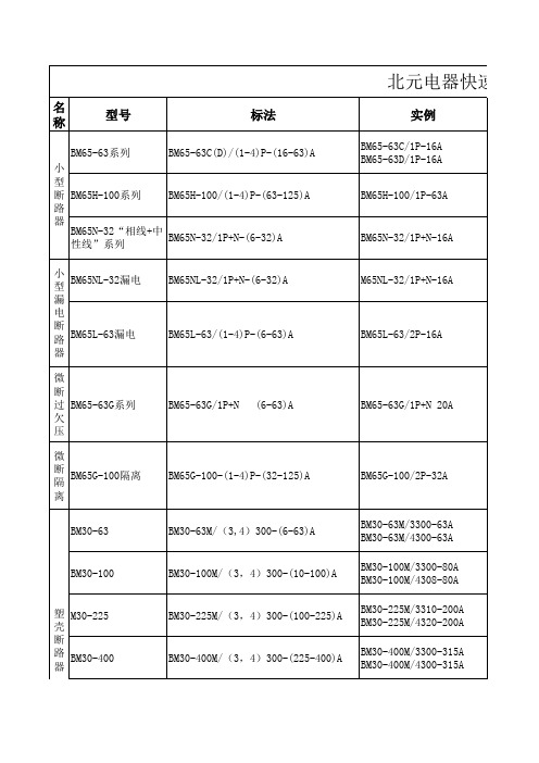
型号
标法
BM65-63系列
BM65-63C(D)/(1-4)P-(16-63)A
小
型
断 BM65H-100系列 BM65H-100/(1-4)P-(63-125)A
路
器
BM65N-32“相线+中 性线”系列
BM65N-32/1P+N-(6-32)A
北元电器快速选型表
实例
BM65-63C/1P-16A BM65-63D/1P-16A
BM30E-100/3400 -(10-100)A
BM30L-100/3400B-80A
BM30E-225/3400-(100-250)A BM30E-400/3400-(200-400)A BM30E-630/3400-(400-630)A
BM30L-225/3400B-200A BM30L-400/3400B-350A BM30L-630/3400B-500A
过载、短路、漏电 保护
用于交流50Hz线路,230V
6A、10A、16A、20A、 对建筑和类似场所
25A、32A、40A、50A、 有过载,短路,过 用于交流50Hz线路,230V
63A
欠压保护。
32A、63A、80A、100A、 隔离
用于交流50Hz或60Hz线路,400V以下
6A、10A、16A、20A、 25A、32A、40A、50A、 63A
操作和柜外操作
故障危害。
4000A、5000A、6300A
M65NL-32/1P+N-16A BM65L-63/2P-16A BM65-63G/1P+N 20A BM65G-100/2P-32A
BM30-63
BM30-63M/(3,4)300-(6-63)A
罗赫高压电源驱动器BM61M41RFV-C评估板说明书
During Use
[5] Be careful to not allow conductive objects to come into contact with the board. [6] Brief accidental contact or even bringing your hand close to the board may result in
Bill of Materials Device
Parts Number
Gate Driver
U1
C11 Input Capacitor
C14
Input signal filter
R12, R13 C12, C13
C21 Output Capacitor
C22
R21
Gate
R22
Test pin Spacer
2/7
2019.10
BM61M41RFV-EVK001
User’s Guide
Schematics R12, R13, R21 and R22 are implemented interim resisters for shipment check.பைடு நூலகம்Please replace each resister which can work with Power Device or input device appropriately.
depending on the circumstances, explosion or other permanent damages. [8] Be sure to wear insulated gloves when handling is required during operation.
快速动作片外晶体管保护器数据表4336(2021年9月)取代(2019年1月)说明书
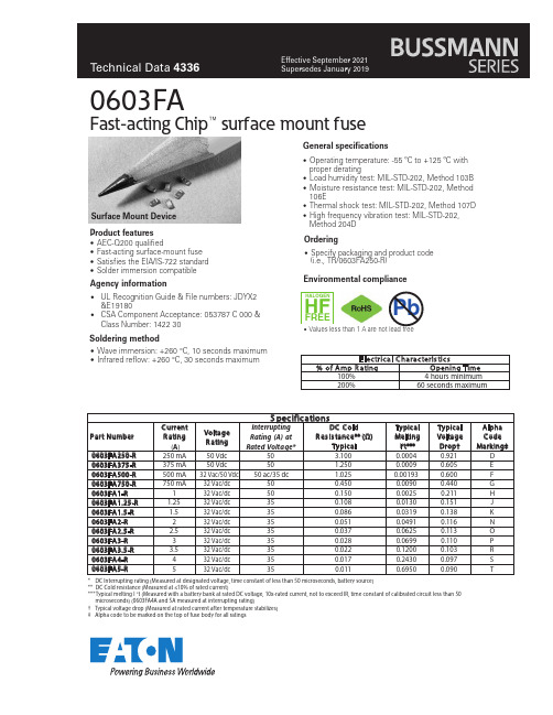
Product features0603FAFast-acting Chip™ surface mount fuse•AEC-Q200 qualified•Fast-acting surface-mount fuse •Satisfies the EIA/IS-722 s tandard •Solder immersion compatibleAgency informationSoldering method•UL Recognition Guide & File numbers: JDYX2&E19180•CSA Component Acceptance: 053787 C 000 &Class Number: 1422 30•Wave immersion: +260 °C, 10 seconds max imum •Infrared reflow: +260 °C, 30 seconds maximumGeneral specifications•Operating temperature: -55 ºC to +125 ºC with proper derating•Load humidity test: MIL-STD-202, Method 103B •Moisture resistance test: MIL-STD-202, Method 106E•Thermal shock test: MIL-STD-202, Method 107D •High frequency vibration test: MIL-STD-202,Method 204DOrdering•Specify packaging and product code(i.e., TR/0603FA250-R)Surface Mount Device S pecificationsC urrent Interrupting Rating (A) at Rated Voltage*DC C old R es is tance** (Ω)Typical Typical Typical Alpha Part Number R ating Voltage Melting Voltage C ode (A )R ating I 2t***Drop†Marking‡0603FA250-R 250 mA 50 Vdc 50 3.1000.00040.921D 0603FA375-R 375 mA 50 Vdc 50 1.2500.00090.605E 0603FA500-R 500 mA 32 Vac/50 V dc 50 ac/35 dc1.0250.001930.600F 0603FA750-R 750 mA 32 Vac/dc 500.4500.00900.440G 0603FA1-R 132 Vac/dc 500.1500.00250.211H 0603FA1.25-R 1.2532 Vac/dc 350.1080.01300.151J 0603FA1.5-R 1.532 Vac/dc 350.0860.03190.138K 0603FA2-R 232 Vac/dc 350.0510.04910.116N 0603FA2.5-R 2.532 Vac/dc 350.0370.06250.113O 0603FA3-R 332 Vac/dc 350.0280.06990.110P 0603FA3.5-R 3.532 Vac/dc 350.0220.12000.103R 0603FA4-R 432 Vac/dc 350.0170.24300.097S 0603FA5-R532 Vac/dc350.0110.69500.090T*DC Interrupting rating (Measured at designated voltage, time constant of less than 50 microseconds, battery source)**DC Cold resistance (Measured at ≤10% of rated current)***Typical melting I t (Measured with a battery bank at rated DC voltage, 10x-rated current, not to exceed IR, time constant of calibrated circuit less than 50microseconds) (0603FA4A and 5A measured at interrupting rating)†Typical voltage drop (Measured at rated current after temperature stabilizes)‡Alpha code to be marked on the top of fuse body for all ratingsPbHALOGENHF FREEEnvironmental compliance•Values less than 1 A are not lead freeEatonElectronics Division 1000 Eaton Boulevard Cleveland, OH 44122United States/electronics © 2021 EatonAll Rights Reserved Printed in USAPublication No. 4336 September 2021Life Support Policy: Eaton does not authorize the use of any of its products for use in life support devices or systems without the express written approval of an officer of the Company. Life support systems are devices which support or sustain life, and whose failure to perform, when properly used in accordance with instructions for use provided in the labeling, can be reasonably expected to result in significant injury to the user.Eaton reserves the right, without notice, to change design or construction of any products and to discontinue or limit distribution of any products. Eaton also reserves the right to change or update, without notice, any technical information contained in this bulletin.0603FAFast-acting Chip™ surface mount fuseTechnical Data 4336Effective September 20211.25(0.05)0.50 0.90(0.035)(0.02)R e c o m m e n d e d P a d L a y o u t – m m /i n c h e sD i m e n s i o n s – m m /i n c h e sDrawing Not to ScaleTime C urrent CurvePackaging CodePackaging Code PrefixDes criptionTR 5,000 fuses on paper tape and reeled on a 178 mm (7 inch) diameter reel per EIA Standard 481-1Current (A)T i m e i n s e c o n d sEaton is a registered trademark.All other trademarks are property of their respective owners.Follow us on social media to get the latest product and support information.。
常见模具钢密度

常见模具钢材的密度常见模具钢材的密度常见钢料的密度,常用单位g/cm3=0.000001kg/mm31、普通钢铁:7.85g/cm32、铜的密度:8.90g/cm3,黄铜密度8.50-8.80,其中59、62、65、68号黄铜的密度是8.50,80、85、90黄铜的密度是8.70 3、模具钢:冷作钢:Cr12密度(7.78g/cm3)Cr12Mov密度(7.85g/cm3)D2密度,SKD11密度,DC11密度,SLD密度全都是7.85g/cm3高速工具钢:SKH9密度,W6Mo5Cr4V2,M2,M35,M42,SKH51密度,MH51,YXM1密度都是8.25g/cm3粉末高速钢: asp-23密度,asp30密度,asp60密度都是8.25g/cm3钨钢/硬质合金:YG20密度 13.50 YG15密度14.2 YG11密度度14.50 YG8密度14.80常用物质表(1g/cm3=1000kg/m3=1吨/立方米)材料名称(g/cm3) 材料名称(g/cm3)水 1.00 玻璃 2.60冰 0.92 铅 11.40银 10.50 酒精 0.79水银(汞) 13.60 汽油 0.75灰口铸铁 6.60-7.40 软木 0.25白口铸铁 7.40-7.70 锌 7.10可锻铸铁 7.20-7.40 纯铜材 8.90铜 8.90 59、62、65、68 黄铜 8.50铁 7.86 80、85、90 黄铜 8.70铸钢 7.80 96 黄铜 8.80工业纯铁 7.87 59-1、63-3 铅黄铜 8.50普通碳素钢 7.85 74-3 铅黄铜 8.70优质碳素钢 7.85 90-1 锡黄铜 8.80碳素工具钢 7.85 70-1 锡黄铜 8.54易切钢 7.85 60-1和62-1 锡黄铜 8.50锰钢 7.81 77-2 黄铜 8.6015CrA铬钢 7.74 67-2.5、66-6-3-2、60-1-1黄铜 8.5020Cr、30Cr、40Cr 铬钢 7.82镍黄铜 8.50 38CrA铬钢 7.80锰黄铜 8.50铬、钒、镍、钼、锰、硅钢 7.857-0.2、6.5-0.4、6.5-0.1、4-3锡青铜 8.80 纯 2.70 5-5-5铸锡青铜 8.80铬镍钨钢 7.80 3-12-5铸锡青铜8.69铬钼钢 7.65 铸镁 1.80含钨9高速工具钢 8.30 工业纯钛(TA1、TA2、TA3)4.50含钨18高速工具钢 8.70 超硬 2.850.5镉青铜 8.90 LT1特殊 2.750.5铬青铜 8.90 工业纯镁 1.7419-2青铜 7.60 6-6-3铸锡青铜 8.82 9-4、10-3-1.5青铜 7.50 硅黄铜、镍黄铜、铁黄铜 8.5010-4-4青铜 7.46 纯镍、阳极镍、电真空镍 8.85高强度合金钢 ` 7.82 镍铜、镍镁、镍硅合金 8.85轴承钢 7.81 镍铬合金 8.727青铜 7.80 锌锭(Zn0.1、Zn1、Zn2、Zn3) 7.15铍青铜 8.30 铸锌 6.863-1硅青铜 8.47 4-1铸造锌合金 6.90 1-3硅青铜 8.60 4-0.5铸造锌合金6.751铍青铜 8.80 铅和铅锑合金 11.37 1.5锰青铜 8.80 铅阳极板 11.335锰青铜 8.60 4-4-2.5 锡青铜8.75金 19.30 5青铜 8.204-0.3、4-4-4锡青铜 8.90 变形镁 MB1 1.76 不锈钢0Cr13、1Cr13、2Cr13、3Cr13、4Cr13 、Cr17Ni2、Cr18、9Cr18、Cr25、Cr28 7.75 MB2、MB8 1.78Cr14、Cr17 7.70 MB3 1.790Cr18Ni9、1Cr18Ni9、1Cr18Ni9Ti、2Cr18Ni9 7.85 MB5、MB6、MB7、MB151.801Cr18Ni11Si4A1Ti 7.52 锻 LD8 2.77 不锈钢 1Crl8NillNb、Cr23Ni18 7.90 LD7、LD9、LD10 2.802Cr13Ni4Mn9 8.50 钛合金 TA4、TA5、TC6 4.453Cr13Ni7Si2 8.00TA6 4.40 白铜 B5、B19、B30、BMn40-1.5 8.90TA7、TC5 4.46 BMn3-12 8.40 TA8 4.56 BZN15-20 8.60 TB1、TB2 4.89BA16-1.5 8.70 TC1、TC2 4.55BA113-3 8.50 TC3、TC4 4.43 锻 LD2、LD30 2.70 TC7 4.40LD4 2.65 TC8 4.48LD5 2.75 TC9 4.52 防锈 LF2、LF43 2.68 TC10 4.53LF3 2.67 硬 LY1、LY2、LY4、LY6 2.76LF5、LF10、LF11 2.65 LY3 2.73LF6 2.64 LY7、LY8、LY10、LY11、LY14 2.80LF21 2.73 LY9、LY12 2.78LY16、LY17 2.84。
三菱电机 采用光纤网络的先进伺服系统 说明书
EC97J1113MELSERVO-J3 不断发展的新一代伺服高速定位改善平滑时间SmallMR-J370MR-J2-Super16816840120404040MR-J31682307010MR-J2-Super6000(r/min)HC-KFSHF-KP 实现高速度、高精度紧凑灵活54321100020003000400050006000(r/min)(例)400W3000r/minHF-KP HC-KFS高速度,高转矩电机HF 系列●转矩(N ·m )最大运行范围持续运行范围功率提升!高速度(6000r/min)和高性能速度频率响应(900Hz)缩短定位时间。
●速度更快!时间速度更短的定位时间HF-MP/HF-KP 系列的最大速度已经提高到6000r/min ,HF-SP2000r/min 系列达到3000r/min 。
●高度精确运行改善机器性能高分辨率编码器262144p/rev(18-位)作为标准部件实现低速时的稳定性。
降低齿轮转矩以减小电机转矩波动。
●●绝对编码器是标准配置。
如果电池(MR-J3BAT)安装在伺服放大器上,在电源接通时不必再次进行原点回归。
●现有产品 的1/2现有的电机(HC 系列)新的电机(HF 系列)<点转转矩>(注1)<伺服放大器>安装面积比现有型号减少40%(与400W 相比较)。
●可紧凑安装*紧凑安装的工 作环境不同。
(注2)减少40%结构更紧凑!单位:mm●<伺服电机>比现有型号减少20%(例如:HF-MP/HF-KP 系列400W)与三菱HC-MFS/HC-KFS 系列比较减少20%体积更小!●<伺服电机>HF-SP 系列的连接器比已有的HC-SFS 系列更小,可以使用户的系统更加紧凑。
●■接线灵活·伺服放大器端子排采用连接器,因此减少了接线时间。
关于连接器详见此样本中的“外部设备”部分。
安利斯特 ML4803A 100 kHz 至 90 GHz 电源测量仪说明书

ModelPower supplySpecifications •ML4803A indicatorFrequency rangeSensorCoaxial typesFor quasi-millimeter and millimeter wavesDisplayCalibration coefficient, offset value, andreference level setting Power range Range switching Range displayAccuracyAccuracy (at indicator)Zero adjustmentZero settingZero shift between each rangeCalibration oscillator Averaging RF blanking output Recorder output Remote-control Memory function AC power supply DC power supply External battery packOperating temperature SafetyDimensions and mass EMC *1100 kHz to 90 GHzFor high level: MA4701A, MA4703A, MA4705A, MA4601A, MA4603A For low level: MA4702A, MA4704A, MA4602A, MA4604AMP737A, MP738A, MP712A[ ] , MP713A[ ] (used with MA4002A Adapter)MP714A[ ], MP715A[ ], MP716A[ ], MP717A[ ] (used with MA4002B Adapter)W, dBm, or dB (REL) can be selected. 4-digit digital display (20% over range is equipped)Compact analog indicator is built-in (values cannot be used.)Calibration coefficient: 0 to 10 dB (accuracy: 0.01 dB)Offset value: 0 to ±99.99 dB (accuracy: 0.01 dB)Reference level: –99.99 to +99.99 dBm (accuracy: 0.01 dB)MA4701A/4703A/4705A/4601A/4603A full-scale values: –20, –10, 0, +10, +20 dBm (10 µW to 100 mW)MA4702A/4704A/4602A/4604A full-scale values: –60, –50, –40, –30, –20 dBm (1 nW to 10 µW)MP series sensors full-scale values: –20, –10, 0, +10, +20 dBm (10 µW to 100 mW)Automatic or manual (range hold) can be selected.When manual is selected, an arbitrary range can be set unrelated to input levels.Selected range (when range is held) is displayed on range lamps 1 to 5.An under range or over range is also displayed.WATT mode: ±0.5%, dBm mode: ±0.02 dBm, dB (REL) mode: ±0.02 dB Automatically performed by pressing push-button keyMA series sensors: ±0.5% of full scale (typical value) at the highest sensitivity range (range 1)MP series sensors: ±1.0% of full scale (typical value) at the highest sensitivity range (range 1)MA series sensors: ±0.2% of full scale after zero set at the highest sensitivity range MP series sensors±0.8% of full scale: Range 2 after zero set at the highest sensitivity range±0.5% of full scale: Range 3 to 5 after zero set at the highest sensitivity range 50 MHz calibration oscillator is built in. Output connector: N (J)Output power: 1.00 mW (0 dBm)Accuracy: Set to within 0.7% at factory (NIST traceable) ±1.2% worst case for one year 4 sample rates can be selected.Low-level TTL (0 to +0.25 V) in zero set modeHigh-level TTL (5 ±0.25 V) when zero set mode is cancelledDC voltage proportional to indicated value is output (1 V in full-scale display).Output impedance: 1 k Ω, Output connector: BNCGPIB is standard.Front panel functions other than the power switch can be controlled externally.SH1, AH1, T5, L4, SR1, RL1, PP0, DC1, DT0, C0Up to 30 frequencies, calibration coefficient, offset value, and reference level data combinations can be stored.100 V +10–15%, 50/60 Hz, <20 VA+7 to +12 V, ≤13 VAContinuous operation with MZ5003A Battery Pack: 5 hours 0˚ to 50˚C213 (W) x 88 (H) x 250 (D) mm, ≤3 kg EN61010-1: 1993 (Installation Category ΙΙ, Pollution Degree ΙΙ)EN55011: 1991, Group 1, Class A EN50082-1: 1992*1: Electromagnetic Compatibility•Coaxial-type power sensorsAmorphous power sensorFrequency range Nominal impedanceMeasured power range Maximum input power Linearity Input connector Dimensions and massMaximum VSWRMA4701A 10 MHz to 18 GHz50 Ω–30 to +20 dBm (1 µW to 100 mW)300 mW in average±3% in only +10 to +20 dBm rangeN34 (W) x 25 (H) x 98 (L)mm, ≤200 g1.4 (10 to 30 MHz)1.18 (30 to 50 MHz)1.1 (50 MHz to 2 GHz)1.18 (2 to 12.4 GHz)1.28 (12.4 to 18 GHz)MA4703A 50 MHz to 26.5 GHzAPC-3.534 (W) x 25 (H) x 87 (L) mm, ≤200 g1.15 (50 to 100 MHz)1.10 (0.1 to 2 GHz)1.15 (2 to 12.4 GHz)1.20 (12.4 to 18 GHz)1.25 (18 to 26.5 GHz)MA4705A 50 MHz to 32 GHz1.15 (50 to 100 MHz)1.10 (0.1 to 2 GHz)1.15 (2 to 12.4 GHz)1.20 (12.4 to 18 GHz)1.25 (18 to 26.5 GHz)1.50 (26.5 to 32 GHz)MA4601A 100 kHz to 5.5 GHzN34 (W) x 25 (H) x 98 (L) mm, ≤200 g1.3 (100 to 300 kHz)1.2 (0.3 to 1 MHz)1.1 (1 MHz to 4 GHz)1.2 (4 to 5.5 GHz)MA4603A 100 kHz to 2 GHz75 ΩNC1.4 (100 to 300 kHz)1.15 (300 kHz to 2 GHz)4Dimensions and massRequired adapter typeRequired adapter typeOptional accessoriesMA4001A Range Calibrator (for indicator full-scale calibration)MA4002A Sensor Adapter for quasi-millimeter wave (for MP712A/713A/737A/738A)MA4002B Sensor Adapter for millimeter wave (for MP714A/715A/716A/717A)J0364APC-3.5 to N conversion connector (required for MP4703A/4704A/4705A)J0365NC-J•N-P conversion connector for sensitivity calibration (required for MA4603A/4604A)MP47A Attenuator for sensitivity calibration (30 dB, required for MA4602A/4604A/4702A/4704A)MP721D Fixed Attenuator (20 dB, N-type, 2 W, DC to 12.4 GHz)J0077Fixed attenuator (20 dB, N-type, 2 W, DC to 18 GHz)J0063Fixed attenuator (30 dB, N-type, 10 W, DC to 12.4 GHz)J0078Fixed attenuator (20 dB, N-type, 10 W, DC to 18 GHz)J0395Fixed attenuator (30 dB, N-type, 30 W, DC to 8.6 GHz)J0064A 7 GHz band coaxial waveguide connector (5.8 to 8.2 GHz, N-J to BRJ-7)J0064B 10 GHz band coaxial waveguide connector (10.0 to 15.0 GHz, N-J to BRJ-120)J0064C 10 GHz band coaxial waveguide connector (8.2 to 13.0 GHz, N-J to BRJ-10)J036618 GHz band coaxial waveguide connector (17.7 to 21.2 GHz, SMA-J to FUBR180)J036722 GHz band coaxial waveguide connector (18 to 26.5 GHz, APC-3.5-J to UG-5971U)J036830 GHz band coaxial waveguide connector (26.5 to 34 GHz, APC-3.5-J to UG-5991U)J0632A 18 GHz band coaxial waveguide connector (17.7 to 22 GHz, SMA-J to FUBR180)J0632B 26 GHz band coaxial waveguide connector (22 to 33 GHz, K-J to FUBR260)J0633A Conversion connector (NC-J • BNC75-J)J0633B Conversion connector (NC-J • BNC75-P)J0633C Conversion connector (NC-P • BNC75-J)J0633D Conversion connector (NC-P • BNC75-P)J0633E Conversion connector (NC-P • SP3C-J)J0633F Conversion connector (NC-J • SP3C-P)J0633G Conversion connector (NC-P • SP3C-J)J0633H Conversion connector (NC-P • SP3C-P)J0369T aper waveguide: WRJ-320 (FUBR320)/WRJ-260 (FUBR260)B0183Rack mount kit-1 (for one ML4803A)B0184Rack mount kit-2 (for two ML4803A)B0185Carrying bagB0186Protective front coverJ0370C Sensor cord, 2.5 m (for extension)J0370E Sensor cord, 5 m (for extension)J0370G Sensor cord, 10 m (for extension)MZ5003A Battery Power Supply (for DC operation)J0371DC power cord (for +7 to +12 V power supply)J0008GPIB cable, 2 mDiode power sensorModelFrequency range Nominal impedance Measured power range Maximum input power Linearity Input connector Maximum VSWR MA4702A 10 MHz to 18 GHz50 Ω–70 to –20 dBm (0.1 nW to 10 µW)200 mW in average/peak, 0 Vdc ±2% in only –30 to–20 dBm rangeN34 (W) x 25 (H) x 98 (L) mm, ≤200 g 1.4 (10 to 30 MHz)1.15 (30 MHz to 4 GHz)1.2 (4 to 8 GHz)1.3 (8 to 18 GHz)MA4704A 50 MHz to 26.5 GHzAPC-3.534 (W) x 25 (H) x 87 (L) mm, ≤200 g1.15 (50 MHz to 4 GHz)1.2 (4 to 8 GHz)1.3 (8 to 18 GHz)1.54 (18 to 26.5 GHz)MA4602A 100 kHz to 5.5 GHzN34 (W) x 25 (H) x 98 (L) mm, ≤200 g1.3 (100 to 300 kHz)1.15 (300 kHz to 3 GHz)1.2 (3 to 5.5 GHz)MA4604A 100 kHz to 2 GHz75 ΩNC1.4 (100 to 300 kHz)1.2 (300 kHz to 2 GHz)ModelMP737A 17 to 22 GHz1.6–30 to +20 dBm (1 µW to 100 mW)+22 dBm (160 mW)±3% only +10 to +20 dBm range52ø x 103L mm, ≤450 gMA4002AMP738A 21.7 to 33 GHz1.5MP712A[ ]18 to 26.5 GHz1.6MP713A[ ]26.5 to 40 GHz1.5MP714A[ ]33 to 50 GHz52ø x 78L mm, ≤700 gMA4002BFrequency range Maximum VSWR Measured power range Maximum input power Linearity error Dimensions and mass ModelMP715A[ ]40 to 60 GHz 1.4–30 to +20 dBm (1 µW to 100 mW)+22 dBm (160 mW)±3% in only +10 to +20 dBm range 52ø x 78L mm, ≤700 g (including cord)MA4002BMP716A[ ]50 to 75 GHzMP717A[ ]60 to 90 GHzFrequency range Maximum VSWR Measured power range Maximum input power Linearity error Dimensions and mass •Waveguide sensorsFor quasi-millimeter wavebandPlease select the type of flanges from the below and put its number in the mark [ ].Blank: JIS flange, 1: MIL flange, 4: UG flangeFor millimeter wavebandOrdering informationPlease specify model/order number, name, and quantity when ordering.Model/Order Main frame ML4803A Power MeterStandard accessoriesJ0370A Sensor connecting cord, 1.5 m: 1 pc J0017Power cord, 2.5 m: 1 pc F0018Fuse, 0.5 A:1 pc W0081AE ML4803A operation manual: 1 copy W0081BE ML4803A service manual:1 copySensorsMA4601A Amorphous Power Sensor (coaxial-type)MA4603A Amorphous Power Sensor (coaxial-type)MA4701A Amorphous Power Sensor (coaxial-type)MA4703A Amorphous Power Sensor (coaxial-type)MA4705A Amorphous Power Sensor (coaxial-type)MA4602A Diode Power Sensor (coaxial-type)MA4604A Diode Power Sensor (coaxial-type)MA4702A Diode Power Sensor (coaxial-type)MA4704A Diode Power Sensor (coaxial-type)MP712A[ ]Waveguide Type Sensor *1MP713A[ ]Waveguide Type Sensor *1MP714A[ ]Waveguide Type Sensor *1MP715A[ ]Waveguide Type Sensor *1MP716A[ ]Waveguide Type Sensor *1MP717A[ ]Waveguide Type Sensor *1MP737A Waveguide Type Sensor *1MP738AWaveguide Type Sensor *1Model/Order *1: Refer to the data sheet for ML4803A. Specify waveguide type when ordering.。
赛米控丹佛斯 分立晶闸管 SKT 883 数据表

Capsule Thyristor ThyristorsSKT 883Features∙Hermetic metal case with epoxy insulator∙Capsule package for double sided cooling∙Off-state and reverse voltages up to 1800 V∙Amplifying gateTypical Applications *∙DC motor control(e.g. for machine tools)∙Controlled and half-controlled rectifiers(e.g. for battery charging)∙AC controllers(e.g. for temperature control)∙Recommended snubbernetworke.g. for V RMS≤ 400 V:R = 33 Ω/32 W, C = 1 µFSKTV RSMVV RRM, V DRMVI TRMS = 1800 A (maximum value for continuous operation)I TAV = 880 A (sin. 180 DSC; T c = 85 ºC)500 400 SKT 883/04D900 800 SKT 883/08D1300 1200 SKT 883/12E1700 1600 SKT 883/16E1900 1800 SKT 883/18ESymbol Condition Values Units I TAVI DI RMSsin. 180 ; T C = 100 (85) ºC2 x P8/180; T a = 45 ºC; B2/B62 x P8/180F; T a = 35 ºC; B2/B62 x P8/180; T a = 45 ºC; W1C624 (880)470 / 6851345 / 1870525AAAAI TSM T vj = 25º C ; 10 ms 19000 AT vj = 125º C ; 10 ms 15500 Ai2t T vj = 25º C ; 8,3...10 ms 1805000 A2s T vj = 125º C ; 8,3...10 ms 1200000 A2s V T T vj = 25º C, I T = 2400 A max. 1,51 VV T(TO)T vj = 125º C max. 0,85 Vr T T vj = 125º C max. 0,26 mΩI DD; I RD T vj = 125º C; V DD = V DRM; V RD = V RRM max. 90 mA t gdt grT vj = 25º C; i G = 1A; di G/d t = 1 A/µsV D = 0,67 * V DRM12µsµs (d i/d t)cr(d V/d t)crt qI HI LT vj = 125°CT vj = 125°C; D (E)T vj = 125°CT vj = 25°C; typ. / maxT vj = 25°C; R G = 33 Ω; typ. / maxmax. 125500 (1000)100 (200)150 / 500300 / 2000A/µsV/µsµsmAmA V GTI GTV GDI GDT vj = 25°C; d.c.T vj = 25°C; d.c.T vj = 125°C; d.c.T vj = 125°C; d.c.min. 3min. 200max. 0,25max. 10VmAVmA R th(j-c)R th(j-c)R th(j-c)R th(c-s)T vjT stgcont.; DSCsin. 180; DSC / SSCrec. 120; DSC / SSCDSC / SSC3032 / 6637 / 775 / 10-40...+125-40...+125mK/WmK/WmK/WmK/W°C°C F Mounting force ( SI units ) 13 … 17 kN m approx. 280 g Case B23Fig. 1L Power dissipation vs. forward current Fig. 4 Forward characteristicsFig. 6 Forward current vs. case temperature Fig. 1R Power dissipation vs. ambient temperature Fig. 5 Surge overload current vs. timeFig. 7 Transient thermal impedance vs. timeFig. 9 Gate trigger characteristicsDimensions in mmOrdering code: 38588600 (1 pair) G / HK Leads – Separately availableDimensions in mmCase B23*IMPORTANT INFORMATION AND WARNINGSThe specifications of SEMIKRON products may not be considered as guarantee or assurance of product characteristics ("Beschaffenheitsgarantie"). The specifications of SEMIKRON products describe only the usual characteristics of products to be expected in typical applications, which may still vary depending on the specific application. Therefore, products must be tested for the respective application in advance. Application adjustments may be necessary. The user of SEMIKRON products is responsible for the safety of their applications embedding SEMIKRON products and must take adequate safety measures to prevent the applications from causing a physical injury, fire or other problem if any of SEMIKRON products become faulty. The user is responsible to make sure that the application design is compliant with all applicable laws, regulations, norms and standards. Except as otherwise explicitly approved by SEMIKRON in a written document signed by authorized representatives of SEMIKRON, SEMIKRON products may not be used in any applications where a failure of the product or any consequences of the use thereof can reasonably be expected to result in personal injury. No representation or warranty is given and no liability is assumed with respect to the accuracy, completeness and/or use of an y information herein, including without limitation, warranties of non-infringement of intellectual property rights of any third party. SEMIKRON does not assume any liability arising out of the applications or use of any product; neither does it convey any license under its patent rights, copyrights, trade secrets or other intellectual property rights, nor the rights of others. SEMIKRON makes no representation or warranty of non-infringement or alleged noninfringement of intellectual property rights of any third party which may arise from applications. Due to technical requirements our products may contain dangerous substances. For information on the types in question please contact the nearest SEMIKRON sales office. This document supersedes and replaces all information previously supplied and may be superseded by updates. SEMIKRON reserves the right to make changes.。
台达变频器VE参数设置
F H U
JOG
KPV-CE01 EXT PU
PU
RUN
STOP RESET
主顯示區
可顯示頻率、電流、電壓、異常等
操作器型號 狀態顯示區
分別可顯示驅動器的運轉狀態 運 轉、 停 止、 寸 動、 正轉、 反 轉 、外部、運轉命令來源等
顯示畫面選擇鍵
按此鍵顯示項目逐次變更以供選擇
運轉命令來源選擇鍵
數字右移鍵
H
U
U
F
F
H
Foxboro 43AP Pneumatic Indicating Controllers 产品说明

FIELD DEVICES – CONTROLLERSProduct Specifications43AP Pneumatic Indicating ControllersThese instruments indicate and control pressure, temperature, vacuum, and differential pressure. They provide process industries with a highly dependable and versatile group of instruments.WIDE SELECTION OF MEASURING ELEMENTS Foxboro products offer the widest variety of element constructions and ranges in the industry. This versatility enables the 43AP Series Pneumatic Indicating Controllers to be applied to virtually any process.WIDE CHOICE OF CONTROL MODESOn-off, proportional, proportional plus derivative, proportional plus integral (reset), proportional plus integral plus derivative, differential gap, and automatic shutdown actions are available.BROAD RANGE OF INTEGRAL (RESET) AND DERIVATIVE ADJUSTMENTSThe integral unit has the complete range from0.01to 50 minutes, and the derivative unit from 0.05 to 50 minutes.VARIETY OF OPTIONSThese controllers are available with an extensive list of optional features. Among these are internal bumpless automatic-manual transfer stations (two types), “batch” function, remote pneumatic set point, Type 70 electric contacts, and control valvemounting.PSS 3-1B3 APSS 3-1B3 APage 2OPERATING CONDITIONSACCURACY UNAFFECTED BY MOUNTING STRESSESBoth the control unit and the measurement element are mounted on a rigid steel plate. Thus, these components are isolated from case stresses due to mounting, and dependable accuracy is ensured. POWER FAILURES DO NOT INFLUENCE PROCESS-DRIVEN INDICATIONA power failure and the likely subsequent loss of supply pressure do not influence the process-driven indication.WEATHERPROOF CONSTRUCTIONA glass fiber reinforced case and a gasketed door with a shatterproof polycarbonate window meet IEC IP53 and provide the environmental protection of NEMA®T ype 3.VERSATILE MOUNTINGInstruments may be mounted in a panel, on a flat surface, on a continuous vertical pipe, or on a vertical pipe stub.INTERNAL BUMPLESS AUTOMATIC-MANUAL TRANSFER STATIONThis option provides bumpless-balanceable transfer between automatic and manual control by simple 2-step procedure. Accidental transfer is avoided because the door must be opened to gain access to the transfer station.PERFORMANCE SPECIFICATIONS(Under Reference Operating Conditions unless otherwise specified)AccuracyINPUT TO POINTER±0.5% of span for qualified elements.INPUT TO OUTPUTDepends on measuring element used. Repeatability0.2% of span.Deadband0.1% of span.Ambient Temperature EffectMaximum control point shift at midspan per 55°C (100°F) change within normal operating conditions is 1% of input span.Supply Pressure EffectMaximum control point shift at midspan per 7 kPa (1psi) change within normal operating conditions is 0.2% of input span.OPERATING CONDITIONSAmbient T emperature24 ±2°C(75 ±3°F)–30 and +80°C(–20 and +180°F)–40 and +80°C(–40 and +180°F)Relative Humidity50% ± 10%No Limit No LimitSupply Pressure140 ± 1.4 kPa(20 ± 0.2 psi)115 and 155 kPa(17 and 23 psi)210 kPa(30 psi)FUNCTIONAL SPECIFICATIONSPSS 3-1B3 APage 3 FUNCTIONAL SPECIFICATIONSElementsRefer to “Measuring Element Specifications” on page4 for types, materials, and ranges. Controller ActionOutput signal either increases or decreases with increasing measurement, as specified; action is reversible in the field.Output Signal20 to 100 kPa, 3 to 15 psi, or 0.2 to 1.0 bar or kg/cm2, as specified.Air Consumption (Under normal operation)0.5 m3/h (0.3 cfm) at standard conditions.Output Gauge0 to 200 kPa, 0 to 30 psi, or 0 to 2 bar or kg/cm2, as specified.Set Point AdjustmentBy means of a knob mounted inside the case. PointersSet point and measurement pointers are fluorescent red.ScaleBlack markings on white background; sector-shaped with nominal effective length of 150 mm (6 in). (Refer to Chart and Dial Catalog 600 for available ranges.)Connections (Located in Bottom of Case.) PRESSURE AND VACUUMFor upper range-values up to 14 MPa(2000psi, or 140 bar or kg/cm2):Connections tapped for R1/4 or 1/4 NPT, asspecified.For upper range-values from 14 MPa(2000psi, or 140 bar or kg/cm[sup/2]) up to70 MPa (10000psi, or 700 bar or kg/cm2):Connections threaded for R1/2 or 1/2 NPT,as specified.For upper range-values above 70 MPa (10000psi, or 700 bar or kg/cm2):9/16-18 Aminco® fitting used.PNEUMATICSupply and output connections tapped for1/4NPT.MountingPANELFlush in a panel up to 16 mm (0.6 in) thick.SURFACESuitable for all controllers having internally-mounted elements. Note that this mounting isnot available with heavy duty helical elements.(These elements extend through the back of the case.)PIPEA kit of parts to fit a DN 50 or 2 in vertical pipe.YOKEKit of parts to fit a vertical DN 50 or 2 in pipestub. This mounting scheme is designedspecifically for controllers having rear-mounted differential pressure elements.PSS 3-1B3 A Page 4PHYSICAL SPECIFICATIONSPHYSICAL SPECIFICATIONSEnclosureThe case is a glass fiber reinforced polyester molding, compounded for superior corrosion resistance. The door is glass fiber reinforced phenylene oxide, and has a shatterproofpolycarbonate window, ultraviolet resistant. The overall construction is weatherproof, meets IEC IP53, and provides the environmental protection of NEMA Type 3.FinishCase, gray polyester; door, blue textured polyurethane.Data LabelAluminum data label fastened to inside of door with pressure sensitive adhesive. Includes space for Customer Tag data up to a maximum of 72characters and spaces. For additional space, see optional Customer T ag.Approximate Mass4.8 kg (10.6 lb), excluding element.MEASURING ELEMENT SPECIFICATIONS (To achieve stated Performance Specifications)Differential Pressure Elements (Refer to PSS 3-4A2 A)a.Body and cover material for DE-A is zinc-cobalt; material for DE-B is 316 ss.b.These are zero-based elements. The lower range value is zero and the upper range value is as shown (100% of span). Zerodifferential pressure can be elevated (compound range) so that lower range value is as low as -50% of span; or suppressed so that upper range value is as high as either –150% of span or 50 kPa (200 inH 2O) ∆P , whichever is less.22DE–A,BType 375 and 5020 and 20050 and 500142000140Temperature Elements—Filled Thermal Systems (Refer to PSS 3-3A1 A)T A–1A IA –130 and +315–200 and +60025 and 33040 and 600TA–2A and 2BIIA and IIB–45 and +315–50 and +600Varies with operating temperature (a)T A–3BIIIB–195 and +760–320 and +140070 and 550120 and 1000a.Does not include temperature overrange values. Narrow spans are at low end of range. The maximum span is 215︒C (400︒F)MEASURING ELEMENT SPECIFICATIONS PSS 3-1B3 APage 5Pressure Elements (Refer to PSS 3-2A1 A)P A–CA (d)Absolute Bellows316 ss170 and 240 kPa abs 2.5 and 35 psia P A–MA Absolute Double Spiral316 ss140 and 700 kPa abs20 and 100 psiaPB–AA PB–AM (e)Helical316 ssK-Monel1.4 and 40 MPa1.7 and 14 MPa200 and 6000 psi200 and 2000 psiPB–BA PB–BM (e)Spiral316 ssK-Monel82 and 1400 kPa140 and 1400 kPa12 and 200 psi20 and 200 psiPB–CA Bellows316 ss35 and 200 kPa 4.5 and 29 psiPB–CC Bellows Brass34 and 100 kPa vac30 and 180 kPa 4.9 and 15 psi 4 and 26 psiPB–DF Diaphragm 50 mm (2 in)Cu-Ni-Sn Alloy 6 and 35 kPa vac6 and 70 kPa 0.9 and 5 psi 0.9 and 10 psiPB–PF Diaphragm 75 m (3 in)Cu-Ni-Sn Alloy 2 and 6 kPa vac2 and 10 kPa 0.3 and 0.9 psi 0.3 and 1.5 psiPB–GA (f)Heavy-Duty Helical316 ss0.5 and 200 MPa75 and 30 000 psiPC 3 to 15 PC 3 to 27Receiver (Bellows)Brass20 to 100 kPa Range—3 to 15 psi Range3 to 27 psi Rangea.All elements except Code PC have zero-based ranges. Therefore, the lower range values are zero and the upper range valuesare as listed.b.To convert kPa to bar or kg/cm2, divide kPa value by 100. To convert MPa to bar or kg/cm2, multiply MPa value by 10.c.To convert psi to inH2O, multiply psi value by 27.73. To convert psi to inHg, multiply psi value by 2.036.d.Replacement element not calibrated.e.K-Monel elements comply with NACE Standard MR-01-75.f.Element extends through back of case. Replacement element not recommended. Return instrument to Global CustomerSupport.PSS 3-1B3 A Page 6MODEL CODEMODEL CODEDescription Model Indicating Controller43AP MountingField (Pipe or Y oke, as specified in complete element code)– F Panel or Surface– P Control On-OffA1Proportional 4 to 400%A2Proportional plus Derivative 0.05 to 50 minutesA3Proportional plus Integral (Reset) 0.01 to 50 minutes per repeat A4Proportional plus Integral plus Derivative A5Differential Gap 1 to 100%A7Automatic ShutdownA8Output Signal and Gauge20 to 100 kPa signal; 200 kPa gauge 53 to 15 psi signal; 30 psi gauge 20.2 to 1.0 bar signal; 2 bar gauge60.2 to 1.0 kg/cm 2 signal; 2 kg/cm 2 gauge4Automatic Manual Internal Transfer Switching NoneN Bumpless with 2-position switch, balance gauge, regulator C 2-position nozzle seal switch for manual controlD Optional SuffixRemote Pneumatic Set Point (Not available with pressure elementCodes P A–CA, P A–CC, PB–GA, T ype 70 Contacts, or AS Reference “BA TCH-H”.)– PElements Available (Refer to element specifications tables) (a)a.The 43AP also uses the /E Electronic Servo Element. Refer to PSS 3-1B3 B.Differential pressure, T ype 37 Diaphragm (43AP–F only)/DE–A, –B Absolute pressure, bellows/P A–CA Absolute pressure, double spiral /P A–MA Pressure, helical /–PB–AA, –AM Pressure, spiral /–PB–BA, –BM Pressure, bellows /–PB–CA, –CC Pressure, diaphragm/–PB–DF , –PF Pressure, heavy-duty helical (43AP–F only)/–PB–GA Pressure receiver, bellows/–PCT emperature, Filled Thermal System/–T A–1A, –2A,–2B, –3BExamples: 43AP–P A12N–P/PB–AA; 43AP–FA25C/DE–EOPTIONAL FEATURESPSS 3-1B3 APage 7 OPTIONAL FEATURESBumplessAutomatic-Manual T ransferStation Consists of precision balance tube, regulator, and 2-position switch locatedwithin enclosure. A simple 2-step procedure provides bumpless transferbetween automatic and manual control. A shutoff valve is supplied to allowautomatic controller and relay to be serviced while retaining manual control.See ModelCodeNozzle Seal Switchfor Manual Control An internally mounted 2-position switch provides a simple and inexpensivemethod of achieving manual control. In the manual position, the switch sealsthe nozzle circuit and the output can be changed by varying the controllersupply pressure with an external regulator.See ModelCodeRemote Pneumatic Set Point Integral AirSupply Set Enables the set point to be positioned from a remote source using a standardpneumatic signal. Available over the full span or part of the span.Fixed or adjustable combination pressure regulator and filter with 50mm (2 in)gauge mounted and piped to controllers. Fixed pressure regulator availablewithout gauge. Maximum input 1 MPa, 150 psi, or 10 bar or kg/cm2. NOTE:Not available with panel mounted controllers.See ModelCodeIASType 70 Electric Alarm Contacts This option comprises a rotor unit with up to 5 contacts. Relays are located in aseparate external sheet metal housing. One relay may be supplied to energizeon increasing or decreasing measurement, as specified. Or two relays may be provided, one energizing on increasing measurement and one on decreasing measurement. Relay contacts rating (noninductive load): 5 A at 120 V ac, 2 Aat 240 V ac, and 5 A at 24V ac or dc. Electrical classification: ordinarylocations.C–T/70Control Valve Mounting A 43AP Controller without elements extending from back of case may beassembled on a control valve fitted with a P50 or P110 Actuator at the factory.CVMExternal Connection to IntegralBellows Used when an external feedback signal must be applied to prevent integralcircuit saturation.ECRBExternal Set Point A knob is fitted on door and engages set point adjustment mechanism.ESPHigh “Batch”Modification For processes involving discontinuous control, the integral (reset) function ismodified to prevent overshoot and to initiate immediate corrective action whencontrol is resumed.BA TCH-HGas Tight Case Special case machining and a gasketed 1/2 NPT vent connection permitsoperation of the controller with clean, noncorrosive process gas.GTCExternal Phenolic Nameplate Laminated plastic nameplate 38 X 76 mm (1.5 X 3 in) with white characters ona black background. Maximum of 5 lines with 28characters or spaces 3 mm(0.13 in) high, or 24 characters or spaces 4 mm (0.16 in) high per line.N/PGlass Window inDoor Shatterproof glass window used in areas where abrasive dust can causescratching of standard polycarbonate window under frequent wiping conditions.GIDStainless Steel DataPlate A stainless steel data plate 36 X 40 mm (1.4 X 1.6 in). Maximum of 4lines with11 characters or spaces per line.SCTCustomer T ag Stainless steel tag attached to instrument for customer tag data that doesn't fiton data plate. There can be a maximum of 10 lines of data with 40 charactersper line.MTSPSS 3-1B3 APage 8OPTIONAL FEATURES Tamper-Proof Knob The door knob is removed to prevent unauthorized access to controladjustments. The door is opened with a specially shaped knob.TPKExternal Subpanel forAutomatic-Manual Switching For use only with controllers not having internal transfer switching. Consists ofpressure regulator, nominal 40 mm (1.5 in) gauge, and 2-position transferswitch completely piped and assembled to external subpanel mounted tobottom surface of enclosure. Subpanel is finished in gray. The 1 in AS Code isfor Control Codes A1, A2, A3, A7, and A8. The 2 in AS Code is for ControlCodes A4 and A5. The S in AS Code is gauge in kPa, the E is psi, and the M iskg/cm2.SD–1SSD–1ESD–1MSD–2DSD–2ESD–2Ma.AS is Auxiliary Specification.OPTIONAL FEATURES (CONTINUED)DIMENSIONS - NOMINALPSS 3-1B3 APage 9 DIMENSIONS - NOMINALPSS 3-1B3 APage 10NOTESNOTESPSS 3-1B3 APage 11NOTESInvensys Systems, Inc.10900 Equity DriveHouston, TX 77041United States of America Global Customer Support Inside U.S.:1-866-746-6477Outside U.S.:1-508-549-2424Website: Copyright 1977-2015 Invensys Systems, Inc. All rights reserved.Invensys and Foxboro are trademarks of Invensys Limited, its subsidiaries, and affiliates. All othertrademarks are the property of their respectiveowners.Invensys is now part of Schneider Electric.0715PSS 3-1B3 APage 12ORDERING INSTRUCTIONSOTHER FOXBORO PRODUCTS1. Model Number2. Mounting3. Element T ype, Material, and Range4. Measurement Range5. Measurement Connection6. Scale Range7. Supply Pressure and Output Signal8. Controller Action9. Optional Features 10. T ag and ApplicationThe Foxboro product lines offer a broad range of measurement and instrument products, including solutions for pressure, flow, analytical, temperature, positioning, controlling, and recording.For a list of these offerings, visit our web site at:。
常用钢材磁特性曲线速查手册说明书

目
录
序 前言
第 2 章常用钢材磁特性曲线
14
第 1 章概述
2.1 碳章结构钢
I 2.2 含金结构钢
. . . . . . . . . . . . . . . . . . . . . . 14 41
1. 1 磁现象和磁场
1. 2 磁性材料分费和特点 I.3铁磁性材料磁化的原因 1. 4 磁特性曲线
1. 4.1 磁化过程和技术磁化幽线
用抵梢,对外显示不出瞌性。当外瞌场作用于铁磁物质时,物质内的磁畴将迅速改变成与外
磁场 致的方向,显示出较强的磁性。这种在外磁场作用下瞄畴改变万向的过程,就是住磁
质桩磁化的过程。融化时,磁场力
克服阻力作功。通过磁畴壁的位事
租瞄矩的转动,使各个不同方向的
畴改变到与外磁场方向接近的方问陆仕wmv剑
上来。若克服阻力所需的能量较小, 则磁化过程易于实现,庄之则难于 磁化。图 J -3-1 表示了磁化过程中瞄 畴的这种变化。
瞄力线具有以下持征, ①具有方向性。在磁场中磁力线的每 点只能有 个确走的方向,所以瞄场中的瞌力线 不会相吏 n ②磁力线是闭含的曲线 世有起点,也世有终点。而且这种闭昔且是沿着磁阻最小的方 向进行。 由于磁场中任何二点只有→个确定的方向,当电荷 q 陆著该方向运动时井不查到作用
力,这个方向就是读点的磁场方向。而当电荷以速度 ω 垂直 f 磁场方向运动时,将受到大小 为 f 的作用力。其作用力 foc qv. 即
47
4
2.2 .4 组Mn系钢
51
4
2.2 , 5 cr 系钢
53
2.2.6 CrMo 系钢
70
2.2.1 cr阳系钢…
盯
4
5
格兰富BM系列水泵

[psi]
[bar]
[psi]
4"
0.5
7.25
60
870
6"
0.5
7.25
50*
725*
8"
1
14.5
25*
363*
* 可应要求提供60 bar / 870 psi版本。
额定转速 • 50 Hz: 2870 min-1 • 60 Hz: 3450 min-1
声压等级 • BM 4"和6"增压模块的声压水平低于70 dB(A)。 • BM 8"增压模块的声压水平低于80 dB(A)。 同时参见第11页的章节运行限制。
250
500
750 1000
Q [US GPM]
60 Hz
BM 8"
60 250
80 100 500
150 200
300 400
Q [m³/h]
750 1000
Q [US GPM]
BMhp 17 BMhp 30 BMhp 46 BMhp 60 BMhp 77 BMhp 95 BMhp 125 BMhp 160 BMhp 215
BM 4"
2
4
6 8 10
7.5 10
25
50
60 Hz
BM 6"
BM 8"
20 75 100
40 60 80 100
200
400
Q [m³/h]
250
500 750 1000
Q [US GPM]
TM01 1232 3712
图 2 性能范围, BM 60 Hz
3
性能范围
BMhp 17 BMhp 30 BMhp 46 BMhp 60 BMhp 77 BMhp 95 BMhp 125 BMhp 160 BMhp 215
电感式传感器模拟量输出型BI15-M30-LI-EXI说明书

T 05:04:01+02:00型号BI15-M30-LI-EXI 货号1535554测量范围 [A…B]2…10mm 安装方式齐平修正系数37#钢 = 1; 铝 = 0.3; 不锈钢= 0.7; 黄铜 = 0.4重复性ð 量程范围|A - B|的1 %ð 0.5 %, 热起后0.5小时线性度ð 5 %温度漂移ð ± 0.06 % / K 环境温度-25…+70 °C针对防爆区域应用参考使用说明工作电压14…30VDCat the electrical connection of the sensor 余波ð 10 % U 额定绝缘电压ð 0.5 kV 短路保护是断路/反极性保护是/ 是输出性能2线, 模拟量输出电流输出4…20mA负载电流输出ð [(U -14 V) / 20 mA] k ò开关频率140 Hz认证依据KEMA 03 ATEX 1122 X Issue no. 2内置 电感(L ) / 电容 (C )0 nF / 0 µH防爆标志É II 1 G Ex ia IIB T6 Ga / II 2 D Ex ia IIIC T85°C Db (最大 U = 30 V, I = 120 mA, P = 600 mW)设计圆柱螺纹, M30 x 1.5尺寸64 mm外壳材料金属, CuZn, 镀铬感应面材料塑料, PA 底帽塑料, EPTR 最大扭矩75 Nm 连接电缆线缆材质 5.2 mm, 蓝, LifYY, PVC, 2 m线缆横截面2 x 0.34mm 防震动性55 Hz (1 mm)防冲击性30 g (11 ms)防护等级IP67MTTF751 years 符合SN 29500 (Ed.99) 40 °C认证sATEX 防爆认证 II组设备,设备等级1G,用于气体危险0区sATEX防爆认证,Ⅱ组设备,2D等级,可应用于粉尘危险2区s M30 x 1.5圆柱螺纹s 铜镀铬s 2线, 14…30 VDC s 模拟量输出s 4…20 mA s电缆连接接线图功能原理TURCK模拟量输出型电感式传感器可以实现简单控制。
赛米控丹佛斯 SEMITRANS IGBT模块 SKM600GA12T4 数据表
SEMITRANS ®4Fast IGBT4 ModulesSKM600GA12T4Features•IGBT4 = 4. generation fast trench IGBT (Infineon)•CAL4 = Soft switching 4. generation CAL-diode•Isolated copper baseplate using DBC technology (Direct Bonded Copper) •Increased power cycling capability •With integrated gate resistor•For higher switching frequenzies up to 20kHz•UL recognized, file no. E63532Typical Applications*•AC inverter drives •UPS•Switched reluctance motorRemarks•Case temperature limited to T c = 125°C max.•Recommended T op = -40 ... +150°C •Product reliability results valid for T j = 150°CAbsolute Maximum Ratings SymbolConditions Values UnitIGBT V CES T j =25°C 1200V I C T j =175°CT c =25°C 913A T c =80°C702A I Cnom 600A I CRMI CRM = 3xI Cnom 1800A V GES -20...20V t psc V CC =800V V GE ≤ 15V V CES ≤ 1200VT j =150°C10µs T j-40...175°C Inverse diode I F T j =175°CT c =25°C 707A T c =80°C 529A I Fnom600A I FRM I FRM = 3xI Fnom1800A I FSM t p =10ms, sin 180°, T j =25°C3240A T j -40 (175)°C Module I t(RMS)T terminal =80°C500A T stg -40...125°C V isolAC sinus 50 Hz, t =1min4000VCharacteristics SymbolConditions min.typ.max.UnitIGBT V CE(sat)I C =600A V GE =15V chiplevel T j =25°C 1.80 2.05V T j =150°C 2.20 2.40V V CE0chiplevel T j =25°C 0.80.9V T j =150°C 0.70.8V r CE V GE =15V chiplevel T j =25°C 1.67 1.92m ΩT j =150°C2.50 2.67m ΩV GE(th)V GE =V CE , I C =24mA55.86.5V I CES V GE =0V V CE =1200V T j =25°C 5mA T j =150°C mA C ies V CE =25V V GE =0Vf =1MHz 37.2nF C oes f =1MHz 2.32nF C res f =1MHz2.04nF Q G V GE =- 8 V...+ 15 V 3400nC R Gint T j =25°C 1.3Ωt d(on)V CC =600V I C =600A V GE =±15V R G on =2ΩR G off =2Ωdi/dt on =6000A/µs di/dt off =5200A/µs T j =150°C 177ns t r T j =150°C 90ns E on T j =150°C 74mJ t d(off)T j =150°C 600ns t f T j =150°C 100ns E off T j =150°C 63mJ R th(j-c)per IGBT0.049K/WCharacteristics SymbolConditionsmin.typ.max.UnitInverse diodeV F = V EC I F =600AV GE =0V chiplevelT j =25°C 2.14 2.46V T j =150°C 2.07 2.38V V F0chiplevel T j =25°C 1.3 1.5V T j =150°C 0.9 1.1V r FchiplevelT j =25°C 1.4 1.6m ΩT j =150°C1.92.1m ΩI RRM I F =600A di/dt off =5500A/µs V GE =±15VV CC =600VT j =150°C 420A Q rr T j=150°C92µC E rr T j =150°C 38mJR th(j-c)per diode0.086K/W Module L CE 1520nH R CC'+EE'terminal-chip T C =25°C 0.18m ΩT C =125°C0.22m ΩR th(c-s)per module 0.020.038K/W M s to heat sink M635Nm M t to terminalsM6 2.55Nm M41.12Nm w330gSEMITRANS ® 4Fast IGBT4 ModulesSKM600GA12T4Features•IGBT4 = 4. generation fast trench IGBT (Infineon)•CAL4 = Soft switching 4. generation CAL-diode•Isolated copper baseplate using DBC technology (Direct Bonded Copper) •Increased power cycling capability •With integrated gate resistor•For higher switching frequenzies up to 20kHz•UL recognized, file no. E63532Typical Applications*•AC inverter drives •UPS•Switched reluctance motorRemarks•Case temperature limited to T c = 125°C max.•Recommended T op = -40 ... +150°C •Product reliability results valid for T j = 150°CFig. 1: Typ. output characteristic, inclusive R CC'+ EE'Fig. 2: Rated current vs. temperature I C = f (T C )Fig. 3: Typ. turn-on /-off energy = f (I C )Fig. 4: Typ. turn-on /-off energy = f (R G )Fig. 5: Typ. transfer characteristic Fig. 6: Typ. gate charge characteristicFig. 7: Typ. switching times vs. I C Fig. 8: Typ. switching times vs. gate resistor R GFig. 9: Transient thermal impedance Fig. 10: Typ. CAL diode forward charact., incl. R CC'+ EE'Fig. 11: CAL diode peak reverse recovery current Fig. 12: Typ. CAL diode peak reverse recovery chargeThis is an electrostatic discharge sensitive device (ESDS), international standard IEC 60747-1, Chapter IX* The specifications of our components may not be considered as an assurance of component characteristics. Components have to be tested for the respective application. Adjustments may be necessary. The use of SEMIKRON products in life support appliances and systems issubject to prior specification and written approval by SEMIKRON. We therefore strongly recommend prior consultation of our staff.。
Schneider Electric 电动机驱动器说明书
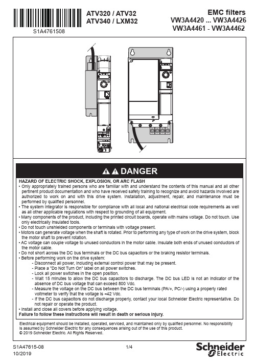
G a
Ø
G
a
H
c
VW3A4422 VW3A4423 VW3A4424 VW3A4425 VW3A4461 VW3A4462
a
bc
mm 107 195 42
(in.) 4.21 7.68 1.65
mm 140 235 50
(in.) 5.51 9.25 1.97 mm 180 305 60
(in.) 7.09 12.01 2.36 mm 245 395 60 (in.) 9.65 15.55 2.35
S1A47615-08
4/4
U/T1 V/T2 V/T3
1,8 N.m 15.9 lbf.in
... (...
Nlb.mf.in)?
M
S1A47615-08
3/4
b e b
H b b H b
VW3A4422 VW3A4423 VW3A4424 VW3A4425
4xØ
c
G
a
d VW3A4461 VW3A4462
voltmeter to verify that the voltage is <42 Vdc. - If the DC bus capacitors do not discharge properly, contact your local Schneider Electric representative. Do
absence of DC bus voltage that can exceed 800 Vdc. - Measure the voltage on the DC bus between the DC bus terminals (PA/+, PC/-) using a properly rated
- 1、下载文档前请自行甄别文档内容的完整性,平台不提供额外的编辑、内容补充、找答案等附加服务。
- 2、"仅部分预览"的文档,不可在线预览部分如存在完整性等问题,可反馈申请退款(可完整预览的文档不适用该条件!)。
- 3、如文档侵犯您的权益,请联系客服反馈,我们会尽快为您处理(人工客服工作时间:9:00-18:30)。
Description
1.
1.1
BM43THA
Description
General Description The BM43THA is a thermopile temperature sensor based on MEMS (micro-electromechanical systems)
TO-46 Package
1/23
Pin Description
2 Pin Descriptions
Table1 Pin Descriptions Pin 1 2 3 4 Function GND Thermistor Thermopile+ Thermistor ThermopileOutput DC voltage+ pin. Description
technology. This thermopile detector consists of thermopile MEMS chip, 5-14um infrared band pass filter, a NTC thermistor for temperature compensation and a large or small size TO-46 Package. 1.2 Features Non-contact surface temperature measuring TO housing with an 5-14um infrared filter Using NTC thermistor for ambient temperature compensation High sensitivity Fast response time Wide working temperature: -40℃ +120℃(Temperature range can be extended to +1000℃by using specific infrared lens) 1.3 Applications Non-contact human body temperature infrared thermometer Microwave oven Automatic induction equipment Heating, Ventilation and Air Conditioning(HVAC) Appliance 1.4 Package
4. Ordering Information ............................................................................................................................................ 16 4.1 Part Numbering ........................................................................................................................................... 16 4.2 TO-46 Package Outline Information ........................................................................................................ 17 4.3 Tray Information .......................................................................................................................................... 18 5. Notice ..................................................................................................................................................................... 19 6. Revision History .................................................................................................................................................... 23
3 Characteristics
3.1 Thermopile Parameter Table 2 Thermopile Parameter Parameter Chip Size Active Area Responsivity Detectivity NEP Voltage Response Thermopile Res TC of Thermopile Noise Voltage Time Constant Field of View(FOV) Operating Temp Storage Temp Thermistor Resistance TC of Thermistor(B) 33 65 Specification Min. Typ. 1.85X1.85 0.7X0.7 60 1.21E08 0.59 29 75 0.1 35 25 104 -40~120 -40~120 37 85 Max. Unit mm2 mm2 V/W cm·Hz /W nW·Hz1/2 V·mm /W k %/℃ nV/Hz1/2 ms ° ℃ ℃
Content
CONTENT
BM43THA
1. Description ........................................................................................................................................................... 1 1.1 1.2 1.3 1.4 2 3 General Description ................................................................................................................................ 1 Features .................................................................................................................................................... 1 Applications .............................................................................................................................................. 1 Package .................................................................................................................................................... 1
Temperature Sensor
BM43THA
Bestow Mascot
Publication Number: BM43THA Revision:1.6 Issue Date:Feb.3,2016
Specification
3.2 Temperature VS Resistance Table Table 3 Temperature VS Resistance Table
@temp=25℃ Degree at 50% signal level
Thermistor for Temperature Compensation 100 3950 k K +3% tolerance, @temp=25℃ ±1% tolerance, Defined at 25/50℃
3/23
Pin Descriptions ............................................................................................................................ 2 Characteristics ..................................................................................................................................................... 3 3.1 Thermopile Parameter ................................................................................................................................. 3 3.2 Temperature VS Resistance Table ............................................................................................................ 4 3.3 Filter Transmission Curve ........................................................................................................................... 7 3.4 Sensitivity Output Curve .............................................................................................................................. 7
