RMII_spec
GMII_RGMII

以太网知识(3)-GMII / RGMII接口作者:luqiliang 日期:2010-5-11 13:24:45字体大小: 小中大本文主要分析MII/RMII/SMII,以及GMII/RGMII/SGMII接口的信号定义,及相关知识,同时本文也对RJ-45接口进行了总结,分析了在10/100模式下和1000M 模式下的连接方法。
4. GMII 接口分析GMII接口提供了8位数据通道,125MHz的时钟速率,从而1000Mbps的数据传输速率。
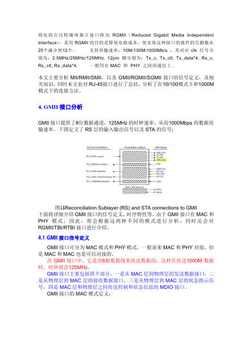
下图定义了RS层的输入输出信号以及STA的信号:图18 Reconciliation Sublayer (RS) and STA connections to GMII下面将详细介绍GMII接口的信号定义,时序特性等。
由于GMII接口有MAC和PHY模式,因此,将会根据这两种不同的模式进行分析,同时还会对RGMII/TBI/RTBI接口进行介绍。
4.1 GMII接口信号定义GMII接口可分为MAC模式和PHY模式,一般说来MAC和PHY对接,但是MAC和MAC也是可以对接的。
在GMII接口中,它是用8根数据线来传送数据的,这样在传送1000M数据时,时钟就会125MHz。
GMII接口主要包括四个部分。
一是从MAC层到物理层的发送数据接口,二是从物理层到MAC层的接收数据接口,三是从物理层到MAC层的状态指示信号,四是MAC层和物理层之间传送控制和状态信息的MDIO接口。
GMII接口的MAC模式定义:注意在表7中,信号GTX_CLK对于MAC来说,此时是Output信号,这一点和MII接口中的TX_CLK的Input特性不一致。
GMII接口PHY模式定义:表8注意在表8中,信号GTX_CLK对于PHY来说,此时是Input信号,这一点和MII接口中的TX_CLK的Output特性不一致。
4.2 GMII接口时序特性在GMII接口中,TX通道参考时钟是GTX_CLK,RX通道参考时钟是RX_CLK,802.3-2005定义了它们之间的关系。
MII接口分析
本文主要分析MII/RMII/SMII,以及GMII/RGMII/SGMII介面的信號定義,及相關知識,同時本文也對RJ-45介面進行了總結,分析了在10/100模式下和1000M模式下的設計方法。
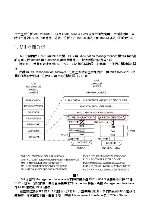
1. MII介面分析MII介面提供了MAC與PHY之間、PHY與STA(Station Management)之間的互聯技術,該介面支持10Mb/s與100Mb/s的數據傳輸速率,數據傳輸的位寬為4位。
提到MII,就有可能涉及到RS,PLS,STA等名詞術語,下面講一下他們之間對應的關係。
所謂RS即Reconciliation sublayer,它的主要功能主要是提供一種MII和MAC/PLS之間的信號映射機制。
它們(RS與MII)之間的關係如下圖:圖1MII介面的Management Interface可同時控制多個PHY,802.3協議最多支持32個PHY,但有一定的限制:要符合協議要求的connector特性。
所謂Management Interface,即MDC信號和MDIO信號。
前面已經講過RS與PLS的關係,以及MII介面連接的對象。
它們是通過MII介面進行連接的,示意圖如下圖。
由圖可知,MII的Management Interface是與STA(StationManagement)相連的。
MII介面支持10Mb/s以及100Mb/s,且在兩種工作模式下所有的功能以及時序關係都是一致的,唯一不同的是時鐘的頻率問題。
802.3要求PHY不一定一定要支持這兩種速率,但一定要描述,通過Management Interface反饋給MAC。
圖2下面將詳細介紹MII介面的信號定義,時序特性等。
由於MII介面有MAC和PHY模式,因此,將會根據這兩種不同的模式進行分析,同時還會對RMII/SMII進行介紹。
1.1 MII介面信號定義MII介面可分為MAC模式和PHY模式,一般說來MAC和PHY對接,但是MAC和MAC也是可以對接的。
SPEC2000使用攻略

SPEC2000使用攻略 首先要有spec2000的测试程序才行,可以通过光盘安装,或者通过一定方式拷贝到本机硬盘进行安装。通过阅 读其中的readme文件按照其中步骤一步步来就是了。 假定安装到了spec2000/目录下。 安装完成之后要配置运行环境,打开一个shell,进入到spec2000目录。 1. $ . shrc 通常是当前shell中运行这样的命令。这样就在当前的shell环境中配置了运行spec2000所需要的环境,否则的 话不能运行的。 2. $ runspec --size=test --noreportable --iterations=1 mcf 这样就可以使用test数据集测试mcf程序了!! 一共有三个测试集test,train,ref , 若想运行ref测试集 , 只需要把上面的—size=ref就可以了。有若干个测试 程序,若想运行gzip程序,只需要改变程序名字为gzip即可。 =============================================== CINT2000程序在不同测试集下的运行方式 代码: <test> bzip2 input.random 2 >input.random.out 2>input.random.err </test> <train> bzip2 pressed 8 >pressed.out 2>pressed.err </train> <ref> bzip2 input.source 58 > input.source.out 2> input.source.err bzip2 input.graphic 58 > input.graphic.out 2> input.graphic.err bzip2 input.program 58 > input.program.out 2> input.program.err </ref>
RPM打包技术和典型SPEC文件分析

7 + cd /usr/src/dist/BUILD
生成的文件会在刚才建立的RPM目录下存在。
2)只生成src格式的rpm包
rpmbuild -bs xxx.spec
生成的文件会在刚才建立的SRPM目录下存在。
3) 只需要生成完整的源文件
rpmbuild -bp xxx.spec
二.典型spec文件分析
通过第一部分的介绍,我们对软件包的管理及spec文件的一些细节应该掌控的差不多了,接下来通过分析kaffeine.spec(kaffeine是linux平台下的媒体播放器)文件来让读者朋友实践一回spec文件的规范和书写。
Kaffeine.spec文件内容如下:
%define debug_package %
1) 只生成二进制格式的rpm包
rpmbuild -bb xxx.spec
用此命令生成软件包,执行后屏幕将显示如下信息:(每行开头为行号)
1 Executing: %prep
2 + umask 022
3 + cd /usr/src/dist/BUILD
4 + exit 0
5 Executing: %build
(3)build段
本段是建立段,所要执行的命令为生成软件包服务,如make 命令。
(4)%install段
本段是安装段,其中的命令在安装软件包时将执行,如make install命令。
(5)%files段
本段是文件段,用于定义软件包所包含的文件,分为三类--说明文件(doc),设置文件(config)及执行程式,还可定义文件存取权限,拥有者及组别。
以太网GMII介绍

以太网知识GMII / RGMII接口本文主要分析MII/RMII/SMII,以及GMII/RGMII/SGMII接口的信号定义,及相关知识,同时本文也对RJ-45接口进行了总结,分析了在10/100模式下和1000M模式下的连接方法。
1. GMII 接口分析GMII接口提供了8位数据通道,125MHz的时钟速率,从而1000Mbps的数据传输速率。
下图定义了RS层的输入输出信号以及STA的信号:图18 Reconciliation Sublayer (RS) and STA connections to GMII下面将详细介绍GMII接口的信号定义,时序特性等。
由于GMII接口有MAC和PHY模式,因此,将会根据这两种不同的模式进行分析,同时还会对RGMII/TBI/RTBI接口进行介绍。
4.1 GMII接口信号定义GMII接口可分为MAC模式和PHY模式,一般说来MAC和PHY对接,但是MAC和MAC也是可以对接的。
在GMII接口中,它是用8根数据线来传送数据的,这样在传送1000M数据时,时钟就会125MHz。
GMII接口主要包括四个部分。
一是从MAC层到物理层的发送数据接口,二是从物理层到MAC层的接收数据接口,三是从物理层到MAC层的状态指示信号,四是MAC层和物理层之间传送控制和状态信息的MDIO接口。
GMII接口的MAC模式定义:注意在表7中,信号GTX_CLK对于MAC来说,此时是Output信号,这一点和MII接口中的TX_CLK的Input特性不一致。
GMII接口PHY模式定义:表8注意在表8中,信号GTX_CLK对于PHY来说,此时是Input信号,这一点和MII接口中的TX_CLK的Output特性不一致。
4.2 GMII接口时序特性在GMII接口中,TX通道参考时钟是GTX_CLK,RX通道参考时钟是RX_CLK,802.3-2005定义了它们之间的关系。
图19 GMII signal timing at receiver input由图19可知,Spec只定义了TX通道和RX通道中接收端Setup时间和Hold时间。
linux-RPM 打包原理 SPEC 编写规范

%patch 最简单的补丁方式,自动指定patch level。
%patch 0 使用第0个补丁文件,相当于%patch ?p 0。
%patch -s 不显示打补丁时的信息。
%patch -T 将所有打补丁时产生的输出文件删除。
引用install -d $RPM_BUILD_ROOT/
cp -a * $RPM_BUILD_ROOT/
%clean 清理临时文件
通常内容为:
引用[ "$RPM_BUILD_ROOT" != "/" ] && rm -rf "$RPM_BUILD_ROOT"
rm -rf $RPM_BUILD_DIR/%{name}-%{version}
%patch 打补丁
通常补丁都会一起在源码tar.gz包中,或放到SOURCES目录下。一般参数为:
%patch -p1 使用前面定义的Patch补丁进行,-p1是忽略patch的第一层目录
%Patch2 -p1 -b xxx.patch 打上指定的补丁,-b是指生成备份文件
◎补充一下
%install
install -d $RPM_BUILD_ROOT%{userpath}
cp -a %{name}* $RPM_BUILD_ROOT%{userpath}
%clean
rm -rf $RPM_BUILD_ROOT
rm -rf $RPM_BUILD_DIR/%{name}-%{version}
Group: 软件分组,建议使用标准分组
rmi入门教程,简单明了(转)

rmi入门教程,简单明了(转)2007-02-02JAVA RMI 实例博客分类:•JAVA技术JAVA RMI 快速入门实例本实例为参考多篇文章写就而成,网上及书上各类文章介绍如何使用RMI有多种实例可参考,譬如有:1. 用命令rmiregistry启动RMI注册服务的2. 同时创建存根(stub)和骨架(skeleton)的3. 只创建存根类的的(jdk1.2以后版本)4. 通过RemoteRef和rmi://协议字串方式的5. 比较少讲到的用LocateRegistry直接在代码上启动RMI注册服务的。
以上描述并非明显分类,比如,你总是可以选择用rmiregistry或者代码LocateRegistry启动RMI注册服务下面我将介绍一个完整的实例,让初学者能快速体验RMI的功用。
分为以下四个步骤1. 创建远程接口及声明远程方法(HelloInterface.java)2. 实现远程接口及远程方法(继承UnicastRemoteObject)(Hello.java)3. 启动RMI注册服务,并注册远程对象(HelloServer.java)4. 客户端查找远程对象,并调用远程方法(HelloClient)5. 执行程序:启动服务HelloServer;运行客户端HelloClient进行调用具体代码及对应步骤如下:代码如何编译这里就不细讲(1)打开一个Dos窗口执行命令 java com.unmi.HelloServer 启动服务HelloServerE:workspaceTestRMIbin>java com.unmi.HelloServerHello Server is ready.运行成功则可以看到 Hello Server is ready(2)打开另一个Dos窗口执行命令 java com.unmi.HelloClient 运行客户端程序E:workspaceTestRMIbin>java com.unmi.HelloClientHello, world!调用成功则可以看到Hello, world!并且在启动服务端的窗口中看到紧跟 Hello Server is ready. 打印出Called by HelloClient如果您能一路顺畅的执行到这里,恭喜!您已度过了一个轻快的RMI之旅。
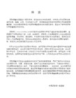
8.6.2 编译RPM 包——spec 文件[共2页]
![8.6.2 编译RPM 包——spec 文件[共2页]](https://img.taocdn.com/s3/m/ff4b6d99767f5acfa0c7cd30.png)
130config.status: creating src/Makefileconfig.status: creating nano.specconfig.status: creating config.hconfig.status: executing depfiles commandsconfig.status: executing default-1 commandsconfig.status: creating po/POTFILESconfig.status: creating po/Makefileconfigure脚本会对系统环境进行检测,如果没有问题即可安装。
如果出问题可能是缺少开发用的某些软件或者版本不合适,以及可能是缺少相应的开发库(devel库)。
如果遇到这类问题,可以具体问题具体分析,此处只介绍配置无异常的情况。
编译和测试的指令分别为make和make test,二者可以一起执行make&&make test。
本例中nano没有为测试编写make test入口,因此只使用make进行编译,示例如下所示。
[root@localhost nano-2.3.1]# makemake all-recursivemake[1]: Entering directory '/root/nano-2.3.1'Making all in docmake[2]: Entering directory '/root/nano-2.3.1/doc'Making all in manmake[3]: Entering directory '/root/nano-2.3.1/doc/man'make all-recursivemake[4]: Entering directory '/root/nano-2.3.1/doc/man'Making all in frmake[5]: Entering directory '/root/nano-2.3.1/doc/man/fr'make all-ammake[6]: Entering directory '/root/nano-2.3.1/doc/man/fr'//以下省略若干内容...mv -f .deps/winio.Tpo .deps/winio.Pogcc -g -O2 -o nano browser.o chars.o color.o cut.o files.o global.o help.o move.o nano.o prompt.o rcfile.o search.o text.o utils.o winio.o -lncurseswmake[2]: Leaving directory '/root/nano-2.3.1/src'make[2]: Entering directory '/root/nano-2.3.1'make[2]: Leaving directory '/root/nano-2.3.1'make[1]: Leaving directory '/root/nano-2.3.1'如果编译顺利结束(无错误或致命错误),并且测试通过(如果有测试)则可以安装。
友声收银系列电子秤使用说明书
是整机保修一年收银系列使用说明书适用型号TM-30A /TM-15A / TM-6AJB-30A / JB-15A / JB-6A2009年7月Version2.30A上海友声衡器有限公司 & 上海精函衡器有限公司沪制00000033号沪制00000319号地址:上海市闵行区莘庄工业区春光路99弄58号邮编:201108厂址:上海市崇明县庙镇经济开发区宏海公路349号邮编:202165 公司总机:(021)54831805/6/7/8 技术部总机:(021)54831858传真:(021)54831803 主页:指定代理与售后服务电话:联系人:感谢您使用上海精函有限公司的产品!在您开始使用本产品前,请务必仔细阅读《前言》中的内容,并严格遵守这些事项!1.1注意事项➢确保电源插头和电源线连接正常,使用三芯电源线进行连接,如果使用了拖线板,则拖线板的插口也要是三芯的,确保三芯的地线妥善的与建筑大地连接,以避免漏电的情况。
➢切勿用沾湿的手插拔电源插头,这样可能导致触电。
➢严禁将身体重力压在秤盘上,以免损坏称重传感器。
➢严禁撞击重压,或用重物冲击秤盘,以免损坏称重传感器,同时勿超过其最大称量范围。
➢严禁淋雨或用水冲洗;如不慎沾水,请用干布擦试干净;若秤体工作异常,请尽速送到经销商处,我们将竭诚为您服务。
➢严禁将条码秤置于极低温、高温或潮湿的场所,这样可能导致秤体工作异常甚至损坏。
➢严禁用有机化学溶剂擦拭外壳和面板。
➢严禁私自打开秤体,也不要让非专业的维修人员修理本秤。
➢严禁将手从打印机旋出位置伸入,该行为可能造成220V触电。
➢在有本公司专业维修人员指导下打开秤体时,请务必提前拔出220V的交流供电。
➢不要试图拆卸秤体内的开关电源,高压电容需要非常长时间才能完全放电,未放电的情况下拆卸可能导致触电。
➢建议使用本厂出售的热敏纸,本秤体对本厂出售的热敏纸进行过长时间的测试与优化,可以较好的保证头片的使用寿命。
rmi认证标准(一)
rmi认证标准(一)RMI认证标准简介RMI(Remote Method Invocation)是一种在分布式系统中通过网络实现远程方法调用的技术。
它允许程序在不同的Java虚拟机(JVM)上进行通信和交互,提供了便捷的远程对象访问和调用方式。
RMI认证的重要性在分布式系统中,因为涉及跨网络的通信,安全性成为一个非常重要的问题。
RMI认证标准的出现,旨在确保远程调用的安全性和可靠性。
RMI认证标准的原则RMI认证标准主要基于以下原则:1.身份认证:确保通信双方的身份真实可信,避免伪造身份进行非法操作。
2.数据完整性:保证数据在传输过程中不被篡改或损坏,防止信息泄露和数据丢失。
3.数据机密性:提供数据传输的加密机制,防止信息被窃取或监听。
4.可靠性:保证通信的稳定性和可靠性,避免数据丢失或通信中断。
RMI认证实现方式以下是几种常用的RMI认证实现方式:•基于密码的认证:通信双方在建立连接时,通过验证密码或密钥来进行身份认证。
这种方式简单高效,但若密码泄露则安全性受到威胁。
•基于数字证书的认证:通过使用数字证书对通信双方的身份进行验证。
数字证书包含了公钥、证书颁发机构(CA)的签名等信息,通过验证证书的合法性,可以确保通信双方的身份真实可信。
•基于加密算法的认证:使用对称加密算法或公钥加密算法对通信数据进行加密,确保数据的机密性和完整性。
加密算法的选择和使用密钥管理等方面对安全性至关重要。
•基于防火墙的认证:通过防火墙对网络流量进行过滤和验证,仅允许符合一定要求的通信通过。
防火墙可以配置访问控制策略,限制只有通过认证的主机才能建立连接,从而增加通信的安全性。
RMI认证的未来发展随着互联网技术的不断发展,RMI认证标准也在不断完善和演进。
未来,我们可以预见以下发展趋势:1.多因素认证:结合密码、生物特征等多种因素进行认证,提高身份验证的安全性。
2.智能合约认证:通过智能合约实现自动化、去中心化的认证过程。
华为设备MML脚本参数名中英文对照表

含义中国为460TD:00 联通GSM:01 移动GSM:02 电信CDMA:03在PLMN中唯一的标识一个区域在PLMN中唯一的标识一个路由区和小区标识一致载频频点值除5得到对应的MHz值辅一频点和主频点之间间隔一个频点,如主频点为10096,辅一则设置为10112小区内所有载波的发射功率之和必须小于等于小区的发射功率(步长取0.1),设置太大, 可能会导致用户的下行功率太大, 从而增加对邻小区的干扰,此参数如果设置的太小, 可能会导致用户的下行发射功率无法上调, 缩小小区覆盖半径此参数的设置是相对于双码道PCCPCH的相对功率,设置太大对其他小区造成下行干扰;设置太小UE可能会搜索不到合适的小区,无法下行同步,现网设置:30,步长0.1dB该参数配置越大,NodeB发送FPACH脉冲的实际发射功率就越大,UE正确收到FPACH信号的成功率就越大,但是同时对系统的干扰也就越大,步长取0.1dB该值定义为PCH相对于小区PCCPCH发射功率的功率偏移。
该参数设置过小,会使得小区边缘UE 无法正确接收寻呼信息,影响下行公共信道覆盖,从而最终影响小区覆盖;设置过大,则会对其它信道产生干扰,并且占用下行发射功率,影响小区容量用于指示PICH上相对于PCCPCH的发射功率现网配置为1(单位:次)现网配置为20(单位:次)现网配置为200(步长取0.1,单位:s)<FALSE>代表否,<TRUE>代表是,现网设置:FALSE用于用户接入小区时区分小区现网设置INACTIVE,表示去激活现网设置INACTIVE,表示去激活用来决定小区的接收时间偏差测量结果是否上报。
<APPLIED>代表激活,<NOTAPPLIED>代子帧中的第二个转换点该值不是小区偏置,该值加上本小区测量值作为测量结果用于事件评估的过程,改值越大,切换条件越不容易满足,切出越困难,易进难出<SUPPORT>代表支持,<NOT_SUPPORT>代表不支持PCCPCH的发射功率决定了小区的覆盖半径,该参数设置太大可能导致上行功率受限,小区覆盖边缘UE无法接入;后台设置值为单码道功率只有当UE测量的PCCPCH-RSCP值大于该门限时,才会驻留到该小区,现网设置-103dBm一般设置允许UE的最大发射发射功率为24,测试时如果该值超过8基本可以认为存在上行干扰了指当前服务小区涉及重选的滞后量,主要用于避免频繁的小区重选,缺省值:4;步长为1;单现网设置:NOT_SUPPORT现网设置:0,步长取0.5指当前服务小区涉及重选的时间滞后量,主要用于避免乒乓重选该设置值和最小接入电平有直接关系,该设置减去最小接入电平作为启动同频重选测量的门限该设置值和最小接入电平有直接关系,该设置减去最小接入电平作为启动异频重选测量的门限该设置值和最小接入电平有直接关系,该设置减去最小接入电平作为启动异系统重选测量的门限该设置也是减去最小接入电平作为启动测量的门限该设置也是减去最小接入电平作为启动测量的门限TS0时隙码道分。
Infoprint 250 導入と計画の手引き 第 7 章ホスト
SUBNETMASK
255.255.255.128
Type of service...............: TOS
*NORMAL
Maximum transmission unit.....: MTU
*LIND
Autostart.....................:
AUTOSTART
*YES
: xx.xxx.xxx.xxx
: xx.xxx.xxx.xxx
*
(
)
IEEE802.3
60 1500
: xxxx
48 Infoprint 250
31. AS/400
IP
MTU
1
1
IPDS TCP
CRTPSFCFG (V3R2)
WRKAFP2 (V3R1 & V3R6)
RMTLOCNAME RMTSYS
MODEL
0
Advanced function printing............:
AFP
*YES
AFP attachment........................:
AFPATTACH
*APPC
Online at IPL.........................:
ONLINE
FORMFEED
*CONT
Separator drawer......................:
SEPDRAWER
*FILE
Separator program.....................:
SEPPGM
*NONE
Library.............................:
RGMII and MAC,PHY
简化的吉比特媒体独立接口称为RGMII(Reduced Gigabit Media Independent Interface)。
采用RGMII的目的是降低电路成本,使实现这种接口的器件的引脚数从25个减少到12个。
支持传输速率:10M/100M/1000Mb/s ,其对应clk 信号分别为:2.5MHz/25MHz/125MHz. 12pin 脚分别为:Tx_c, Tx_ctl, Tx_data*4, Rx_c, Rx_ctl, Rx_data*4. 一般用在MAC 和PHY 之间的通信上。
本文主要分析MII/RMII/SMII,以及GMII/RGMII/SGMII接口的信号定义,及相关知识,同时本文也对RJ-45接口进行了总结,分析了在10/100模式下和1000M 模式下的连接方法。
4. GMII接口分析GMII接口提供了8位数据通道,125MHz的时钟速率,从而1000Mbps的数据传输速率。
下图定义了RS层的输入输出信号以及STA的信号:图18Reconciliation Sublayer (RS) and STA connections to GMII下面将详细介绍GMII接口的信号定义,时序特性等。
由于GMII接口有MAC和PHY模式,因此,将会根据这两种不同的模式进行分析,同时还会对RGMII/TBI/RTBI接口进行介绍。
4.1 GMII接口信号定义GMII接口可分为MAC模式和PHY模式,一般说来MAC和PHY对接,但是MAC和MAC也是可以对接的。
在GMII接口中,它是用8根数据线来传送数据的,这样在传送1000M数据时,时钟就会125MHz。
GMII接口主要包括四个部分。
一是从MAC层到物理层的发送数据接口,二是从物理层到MAC层的接收数据接口,三是从物理层到MAC层的状态指示信号,四是MAC层和物理层之间传送控制和状态信息的MDIO接口。
GMII接口的MAC模式定义:注意在表7中,信号GTX_CLK对于MAC来说,此时是Output信号,这一点和MII接口中的TX_CLK的Input特性不一致。
以太网知识(2)-RMII_SMII接口
以太网知识(2)-RMII / SMII接口本文主要分析MII/RMII/SMII,以及GMII/RGMII/SGMII接口的信号定义,及相关知识,同时本文也对RJ-45接口进行了总结,分析了在10/100模式下和1000M 模式下的连接方法。
续--上篇文章“以太网知识(1)-MII接口”1.5 Electrical CharacterMII接口的电气特性可以分为Driver characteristics和Receiver characteristics。
针对于Driver characteristics的DC电气特性而言,Spec要求所有MII接口The high (one) logic level output potential V oh shall be no less than 2.40 V at an output current I oh of –4.0 mA. The low (zero) logic level output potential Vol shall not be greater than 0.40 V at an output current I oL of 4.0 mA。
这个就是LVTTL常用的逻辑标准。
针对于Driver characteristics的AC电气特性而言,Drivers must also meet certain ac specifications in order to ensure adequate signal quality for electrically long point-to-point transmission paths. The ac specifications shall guarantee the following performance requirements.The initial incident potential change arriving at the receiving end of apoint-to-point MII signal path plus its reflection from the receiving end of the path must switch the receiver input potential monotonically from a valid high (one) level to Vil ≤Vil(max)–200 mV, or from a valid low (zero) level to Vih ≥Vih(min) + 200 mV. Subsequent incident potential changes arriving at the receiving end of a point-to-point MII signal path plus their reflections from the receiving end of the path must not cause the receiver input potential to reenter the range Vil(max) – 200 mV < Vi < Vih(min) + 200 mV except when switching from one valid logic level to the other. Such subsequent incident potential changes result from a mismatch between the characteristic impedance of the signal path and the driver output impedance。
STM32f10固件库使用手册中文版
UM0427 用户手册32 位基于ARM 微控制器STM32F101xx 与STM32F103xx固件函数库介绍本手册介绍了32 位基于ARM 微控制器STM32F101xx 与STM32F103xx 的固件函数库。
该函数库是一个固件函数包,它由程序、数据结构和宏组成,包括了微控制器所有外设的性能特征。
该函数库还包括每一个外设的驱动描述和应用实例。
通过使用本固件函数库,无需深入掌握细节,用户也可以轻松应用每一个外设。
因此,使用本固态函数库可以大大减少用户的程序编写时间,进而降低开发成本。
每个外设驱动都由一组函数组成,这组函数覆盖了该外设所有功能。
每个器件的开发都由一个通用API (application programming interface 应用编程界面)驱动,API 对该驱动程序的结构,函数和参数名称都进行了标准化。
所有的驱动源代码都符合“Strict ANSI-C”标准(项目于范例文件符合扩充ANSI-C 标准)。
我们已经把驱动源代码文档化,他们同时兼容MISRA-C 2004 标准(根据需要,我们可以提供兼容矩阵)。
由于整个固态函数库按照“Strict ANSI-C”标准编写,它不受不同开发环境的影响。
仅对话启动文件取决于开发环境。
该固态函数库通过校验所有库函数的输入值来实现实时错误检测。
该动态校验提高了软件的鲁棒性。
实时检测适合于用户应用程序的开发和调试。
但这会增加了成本,可以在最终应用程序代码中移去,以优化代码大小和执行速度。
想要了解更多细节,请参阅Section 2.5。
因为该固件库是通用的,并且包括了所有外设的功能,所以应用程序代码的大小和执行速度可能不是最优的。
对大多数应用程序来说,用户可以直接使用之,对于那些在代码大小和执行速度方面有严格要求的应用程序,该固件库驱动程序可以作为如何设置外设的一份参考资料,根据实际需求对其进行调整。
此份固件库用户手册的整体架构如下:定义,文档约定和固态函数库规则。
MII接口
JTAG也是一种国际标准测试协议(IEEE 1149.1兼容),主要用于芯片内部测试。现在多数的高级器件都支持JTAG协议,如DSP、FPGA器件等。标准的JTAG接口是4线:TMS、TCK、TDI、TDO,分别为模式选择、时钟、数据输入和数据输出线。 相关JTAG引脚的定义为:TCK为测试时钟输入;TDI为测试数据输入,数据通过TDI引脚输入JTAG接口;TDO为测试数据输出,数据通过TDO引脚从JTAG接口输出;TMS为测试模式选择,TMS用来设置JTAG接口处于某种特定的测试模式;TRST为测试复位,输入引脚,低电平有效。GND
JTAG最初是用来对芯片进行测试的,基本原理是在器件内部定义一个TAP(Test Access Port测试访问口)通过专用的JTAG测试工具对进行内部节点进行测试。JTAG测试允许多个器件通过JTAG接口串联在一起,形成一个JTAG链,能实现对各个器件分别测试。现在,JTAG接口还常用于实现ISP(In-System Programmable;在线编程),对FLASH等器件进行编程。
PCI 外设组件互连标准(Peripheral Component Interconnection)
一种由英特尔(Intel)公司1991年推出的用于定义局部总线的标准。此标准允许在计算机内安装多达10个遵从PCI标准的扩展卡。最早提出的PCI总线工作在33MHz频率之下,传输带宽达到133MB/s(33MHz * 32bit/s),基本上满足了当时处理器的发展需要。随着对更高性能的要求,1993年又提出了64bit的PCI总线,后来又提出把PCI 总线的频率提升到66MHz。目前广泛采用的是32-bit、33MHz的PCI 总线,64bit的PCI插槽更多是应用于服务器产品。从结构上看,PCI是在CPU和原来的系统总线之间插入的一级总线,具体由一个桥接电路实现对这一层的管理,并实现上下之间的接口以协调数据的传送。管理器提供信号缓冲,能在高时钟频率下保持高性能,社和为显卡,声卡,网卡,MODEM等设备提供连接接口,工作频率为33MHz/66MHz。
RMI 的运行逻

RMI 的运行逻
RMI(远程方法调用)是一种在分布式系统中进行远程通信的技术,其运行逻辑如下:
客户端调用远程对象方法:客户端通过本地接口调用远程对象的方法,就像调用本地对象一样。
1.Stub 封装调用参数:本地接口的实现对象,也就是Stub,会将客户端调用方法的参数进行封装,以便进行传输。
2.远程传输:Stub 将封装好的参数通过网络传输给远程对象,即服务器端的Skeleton。
3.Skeleton 解封装参数:Skeleton 接收到远程传输的参数后,将其解封装,并调用实际的远程对象方法进行处理。
4.远程方法调用:远程对象执行客户端请求的方法,返回结果。
5.Skeleton 返回结果:Skeleton 将远程对象执行方法的结果封装,通过网络传输回客户端。
6.Stub 接收结果:Stub 接收到远程传输的结果后,将其解封装,返回给客户端。
RMI 的运行逻辑可以简单地概括为客户端通过本地接口调用远程对象方法,而Stub 和Skeleton 则负责将调用参数和结果进行封装和解封装,并进行网络传输。
这种运行逻辑使得远程方法调用看起来像是本地方法调用一样简单,同时也可以在分布式系统中实现不同节点之间的通信,方便地进行远程操作和数据传输。
Linux系统下使用的磁带机的命令
Linux系统下使用的磁带机的命令Linux 环境使用的磁带机的方式有多种,主要通过Amanda、tar 等软件进行操作。
Amanda是提供了远程集中备份的功能,通过分别设置客户端、服务器端,实现远程集中存储备份。
而T ar主要用于单机环境下,将数据直接写入磁带的备份。
针对单一节点的备份,只要简单的使用Tar命令进行备份、恢复即可。
安装完磁带后,重启服务器,执行dmesg命令可以看到新的磁带机设备叫/dev/st0磁带操作倒带,将磁带卷至起始位置: mt -f /dev/st0 rewind擦除,擦掉磁带上的内容: mt -f /dev/st0 erase注:擦除工作非常慢,并且对磁带有损伤,最好不要执行,当数据写满后,可以继续写入数据并覆盖原有的数据,无须执行擦除操作。
新磁带打开封装后立刻可以使用,不需要执行擦除。
出带,将磁带卷至初始位置然后从磁带机内弹出: mt -f /dev/st0 offline数据操作列出目录操作: tar tvf /dev/st0写入数据操作: tar cvf /dev/st0 <要写入的文件名>注:写入数据的方法有两种:不打包直接写入文件和打包压缩后写入文件。
二者各有优缺点。
不打包直接写入文件的方法,看起来效率低,操作复杂,但是可以提高数据的生存率。
磁带是一种线性存储的设备,所有的数据紧挨着顺序写入。
当磁带的某一点损坏的时候,其余位置的磁带还可以继续读取,其中的文件也能读出来。
如果采用了打包压缩后写入的方法,则磁带上存储的只有一个文件。
当磁带有任何一个地方发生了故障无法读取,则这个压缩文件将缺少一些细节,及时是一个bit的错误,也将导致压缩文件报告CRC错误无法解压。
所以,如果是存储大量的数据,建议直接写入。
如果是存取小文件,则最好打包并给文件名加时间标记写入。
继续写入数据: tar rvf /dev/st0 <要写入的文件名>读取数据: tar xvf /dev/st0 <要读取的文件名>UNIX环境,一般情况下磁带所关联的设备文件为/dev/rmt/0, 下面只举例说明常用的Sun Solaris操作系统下磁带机设备文件和物理设备关联的情况。
- 1、下载文档前请自行甄别文档内容的完整性,平台不提供额外的编辑、内容补充、找答案等附加服务。
- 2、"仅部分预览"的文档,不可在线预览部分如存在完整性等问题,可反馈申请退款(可完整预览的文档不适用该条件!)。
- 3、如文档侵犯您的权益,请联系客服反馈,我们会尽快为您处理(人工客服工作时间:9:00-18:30)。
March 20, 1998Sponsored By:TMRMII TM Specification1.0Overview and ArchitectureThis document comprises a low pin count Reduced Media Independent Interface TM(RMII TM) specification intended for use between Ethernet PHYs and Switch ASICs.Under IEEE 802.3u [2] an MII comprised of 16 pins for data and control is defined. Indevices incorporating many MACs or PHY interfaces such as switches, the number ofpins can add significant cost as the port counts increase. Typical switch products in theindustry today offer 12 to 24 ports in a single device. At 6 pins per port and 1 pin perswitch ASIC, the proposed RMII specification would save 119 pins plus the extra powerand ground pins to support those additional pins for a 12 port switch ASIC.The purpose of this interface is to provide a low cost alternative to the IEEE 802.3u [2]MII as specified in Clause 22 (hereafter referred to as simply “MII”). Architecturally,the RMII specification provides for an additional reconciliation layer on either side ofthe MII but can be implemented in the absence of an MII.The management interface (MDIO/MDC) is assumed to be identical to that defined inIEEE 802.3u [2]. It is assumed that the reader is familiar with IEEE 802.3 [1] and IEEE802.3u [2].The RMII specification has the following characteristics:1.It is capable of supporting 10Mb/s and 100Mb/s data rates2. A single clock reference is sourced from the MAC to PHY (or from an externalsource)3.It provides independent 2 bit wide (di-bit) transmit and receive data paths4.It uses TTL signal levels, compatible with common digital CMOS ASIC processes Rev. 1.21 Copyright AMD Inc., Broadcom Corp., National Semiconductor Corp., and Texas Instruments Inc., 1997See the RMII Consortium Addendum for a complete list of RMII Consortium membersApplication2.0ApplicationThe RMII specification has been optimized for use in high port density interconnectdevices which require independent treatment of the data paths. The primary motivator isa switch ASIC which requires independent data streams between the MAC and PHY.Design considerations for repeaters have not been accounted for in this specification.While repeaters are not precluded from using the RMII specification, no validation ofthe feasibility of their implementation has gone into the definition.The implementation of the interface is assumed to be a chip-to-chip interface imple-mented with traces on a printed circuit board. While other implementations are not pre-cluded, no provision is made in this document for an exposed interface (i.e. noconnector is specified).3.0Design Goals and Trade-offsIn choosing the signaling for the RMII specification, the following criteria was applied:1.Clock frequency of 50 MHz or less to minimize EMI and IC I/O requirements2.Pin count independent of port density of the PHY3.Single synchronous clocking4.Reduction of required control pinsBy doubling the clock frequency 4 pins are saved on the data path alone without sub-stantially impacting ASIC I/O capabilities or requiring clock frequencies of 100MHzwhich can cause significant system level challenges with respect to EMI performance.Further, as long as Start of Packet and End of Packet timing information is preservedacross the interface, the MAC is able to derive the COL signal from the receive andtransmit data delimiters. Of significant impact is preserving Start of Packet informationin both 10 and 100 Mb/s operation since there can be a relatively large delta between theassertion of CRS and RX_DV on the standard IEEE 802.3u MII [2]. However, CRS canbe collapsed together with RX_DV if some additional reconciliation assumptions aremade.RX_ER is important for meeting Hamming Distance requirements. However, PHYshave the possibility of introducing data replacement to guarantee that the CRC offersadequate protection. Similarly, in switch applications there is no need for TX_ER sincea MAC will never generate errored data. The one case where TX_ER is used is withrepeaters that need to ensure propagation of errors. When used in conjunction with datacorruption by the PHY on RX_ER, this becomes a non-issue.A single synchronous reference clock for transmit, receive, and control is used. Thiscorresponds to one output from the switch ASIC. Alternatively, the clock referencecould be sourced from an external device and may correspond to one input to the switchASIC. Each PHY provides a clock reference input. However, only one input is requiredfor multiple PHYs on a single IC. PHYs must provide enough buffering to account forworst case variation between local and recovered clock.2RMII TM Specification Rev. 1.2ConformanceRev. 1.2RMII TM Specification3Since data is not looped back from transmit to receive, the codes corresponding to RXD[1:0] values and TXD[1:0] while TX_EN and/or RX_DV are de-asserted may be used for out of band MAC/PHY signalling.FIGURE 1.Signal Reconciliation Map4.0ConformanceThis document follows IEEE 802 conventions in that the word “shall” indicates a requirement for conformance to this specification. The word “may” indicates a choice or an allowable implementation. All other text is background, explanatory, or recom-mendation.TX_EN TXD[3:0]TX_ER TX_CLK COL CRS RX_DV RXD[3:0]RX_ER RX_CLKRMII PHY I/F to MII PHY I/FCRS_DV RXD[1:0]REF_CLK TXD[1:0]TX_EN50 MHz Reference Clock(Sourced externally or from Switch ASIC)TX_EN TXD[3:0]TX_ER TX_CLKCOL CRS RX_DV RXD[3:0]RX_ER RX_CLKMII MAC I/F to RMII MAC I/F RX_ER**Note:RX_ER is a required output of the PHY . The switchASIC may choose to use this input.Signal Definition4RMII TM SpecificationRev. 1.25.0Signal DefinitionThe PHY shall implement and conform to the requirements for REF_CLK, CRS_DV , RXD[1:0], TX_EN, TXD[1:0], and RX_ER. The MAC interface shall implement and conform to the requirements for REF_CLK, CRS_DV , RXD[1:0], TX_EN and TXD[1:0].5.1REF_CLKReference ClockREF_CLK is a continuous clock that provides the timing reference for CRS_DV , RXD[1:0], TX_EN, TXD[1:0], and RX_ER. REF_CLK is sourced by the MAC or an external source. Switch implementations may choose to provide REF_CLK as an input or an output depending on whether they provide a REF_CLK output or rely on an exter-nal clock distribution device. Each PHY device shall have an input corresponding to this clock but may use a single clock input for multiple PHYs implemented on a single IC. The REF_CLK frequency shall be 50 MHz +/- 50 ppm with a duty cycle between 35% and 65% inclusive. It is assumed that the PHY uses REF_CLK as the network clock such that no buffering is required on the transmit data path.While the PHY may recover clock from the incoming data stream, the receiver shall account for differences between the local REF_CLK and the recovered clock through use of sufficient elasticity buffering. The elasticity buffer design shall not affect the Inter-Packet Gap (IPG) for received IPGs of 36 bits or greater. To tolerate the clock vari-ations specified here for Ethernet MTUs, the elasticity buffer shall tolerate a minimum of +/-10 bits.* This implies that the FIFO is at least 20 bits deep and does not transfer recovered data onto RXD[1:0] until the FIFO is half full.*Note:Some vendors desire toleration of MTUs greater than the Ethernet MTU.TABLE 1.RMII Specification SignalsSignal NameDirection (with respect to the PHY)Direction (with respect to the MAC)UseREF_CLK Input Input or Output Synchronous clock reference for receive, transmit and control interface CRS_DV Output Input Carrier Sense/Receive Data Valid RXD[1:0]Output Input Receive Data TX_EN Input Output Transmit Enable TXD[1:0]Input Output Transmit Data RX_EROutputInput (Not required)Receive ErrorSignal Definition5.2CRS_DVCarrier Sense/Receive Data ValidCRS_DV shall be asserted by the PHY when the receive medium is nonidle. The specif-ics of the definition of idle for 10BASE-T and 100BASE-X are contained in IEEE 802.3[1] and IEEE 802.3u [2]. CRS_DV is asserted asynchronously on detection of carrierdue to the criteria relevant to the operating mode. That is, in 10BASE-T mode, whensquelch is passed or in 100BASE-X mode when 2 non-contiguous zeroes in 10 bits aredetected carrier is said to be detected.Loss of carrier shall result in the deassertion of CRS_DV synchronous to the cycle ofREF_CLK which presents the first di-bit of a nibble onto RXD[1:0] (i.e. CRS_DV isdeasserted only on nibble boundaries). If the PHY has additional bits to be presented onRXD[1:0] following the initial deassertion of CRS_DV, then the PHY shall assertCRS_DV on cycles of REF_CLK which present the second di-bit of each nibble anddeassert CRS_DV on cycles of REF_CLK which present the first di-bit of a nibble. Theresult is: Starting on nibble boundaries CRS_DV toggles at 25 MHz in 100Mb/s modeand 2.5 MHz in 10Mb/s mode when CRS ends before RX_DV (i.e. the FIFO still hasbits to transfer when the carrier event ends.) Therefore, the MAC can accurately recoverRX_DV and CRS.During a false carrier event, CRS_DV shall remain asserted for the duration of carrieractivity.The data on RXD[1:0] is considered valid once CRS_DV is asserted. However, since theassertion of CRS_DV is asynchronous relative to REF_CLK, the data on RXD[1:0]shall be “00” until proper receive signal decoding takes place (see definition ofRXD[1:0] behavior).*Note:CRS_DV is asserted asynchronously in order to minimize latency of control signals through the PHY.5.3RXD[1:0]Receive Data [1:0]RXD[1:0] shall transition synchronously to REF_CLK. For each clock period in whichCRS_DV is asserted, RXD[1:0] transfers two bits of recovered data from the PHY. Insome cases (e.g. before data recovery or during error conditions) a pre-determined valuefor RXD[1:0] is transferred instead of recovered data. RXD[1:0] shall be “00” to indi-cate idle when CRS_DV is deasserted. Values of RXD[1:0] other than “00” whenRX_DV as recovered from CRS_DV is deasserted are reserved for out-of-band signal-ling (to be defined). Values other than “00” on RXD[1:0] while RX_DV as recoveredfrom CRS_DV is de-asserted shall be ignored by the MAC. Upon assertion of CRS_DV,the PHY shall ensure that RXD[1:0]=“00” until proper receive decoding takes place.5.3.1RXD[1:0] in 100 Mb/s modeFor normal reception following assertion of CRS_DV, RXD[1:0] shall be “00” until thereceiver has determined that the receive event has a proper Start of Stream Delimiter.Rev. 1.2RMII TM Specification5Signal Definition6RMII TM SpecificationRev. 1.2Thereafter, preamble will appear (RXD[1:0]=01). Data capture by MACs occur follow-ing detection of SFD.If False Carrier is detected (Bad SSD), then RXD[1:0] shall be “10” until the end of the receive event. This is a unique pattern since False Carrier can only occur at the begin-ning of a packet where preamble will be decoded (i.e. RXD[1:0]=01).5.3.2RXD[1:0] in 10 Mb/s modeFollowing assertion of CRS_DV , RXD[1:0] shall be “00” until the 10BASE-T PHY has recovered clock and is able to decode the receive data. Once valid receive data is avail-REF_CLK CRS_DV RXD[1]RXD[0]00000000000001x x x x x x 001111111xxxxxx/J//K/Preamble SFD DataFIGURE 2.100 Mb/s Reception with no errors*Note:CRS_DV may toggle at 25MHz starting on a nibble boundary if bits accumulate due to the difference between local and recovered clock to allow distinction between CRS and RX_DV . The example waveform shows a single nibble accumulated in the FIFO.REF_CLK CRS_DV RXD[1]RXD[0]0000011111111111111100FIGURE 3.100 Mb/s Reception with False CarrierFalse Carrier detectedSignal Definitionable from the 10BASE-T PHY, RXD[1:0] shall take on the recovered data values (i.e.starting with “01” for preamble).As the REF_CLK frequency is 10 times the data rate in 10Mb/s mode the value onRXD[1:0] shall be valid such that RXD[1:0] may be sampled every 10th cycle, regard-less of the starting cycle within the group and yield the correct frame data.5.3.3RXD[1:0] and Receive Error DetectionThe MII provides the RX_ER signal to ensure propagation of errors when the100BASE-X PHY cannot decode the receive signal properly. To eliminate the require-ment for this signal and still meet the requirements for undetected error rate, RXD[1:0]shall replace the decoded data in the receive stream with “01” until the end of carrieractivity. By replacing the data in the remainder of the frame with a particular pattern, theCRC check will reject the packet as errored.Switches perform CRC checking and will not propagate errored packets. It should alsobe noted that the need for TX_ER is also obviated since its purpose was to enablerepeaters to ensure error propagation without requiring repeaters to alter the data flow-ing through them.In order to ensure the CRC error count is not affected, the PHY shall provide a 16 bitreceive error counter that increments upon detection of RX_ER as defined in section 5.7at most once per carrier event. It is recommended that the receive error counter belocated at 15h within the standard MII register space. If address 15h is not available, thereceive error counter register shall be contained between 10h and 1Fh such that IEEE802.3u [2] MII register space is not affected.5.4TX_ENTransmit EnableTX_EN indicates that the MAC is presenting di-bits on TXD[1:0] for transmission.TX_EN shall be asserted synchronously with the first nibble of the preamble and shallremain asserted while all di-bits to be transmitted are presented. TX_EN shall benegated prior to the first REF_CLK rising edge following the final di-bit of a frame.TX_EN shall transition synchronously with respect to REF_CLK.5.5TXD[1:0]Transmit DataTXD[1:0] shall transition synchronously with respect to REF_CLK. When TX_EN isasserted, TXD[1:0] are accepted for transmission by the PHY. TXD[1:0] shall be “00”to indicate idle when TX_EN is deasserted. Values of TXD[1:0] other than “00” whenTX_EN is deasserted are reserved for out-of-band signalling (to be defined). Valuesother than “00” on TXD[1:0] while TX_EN is deasserted shall be ignored by the PHY. Rev. 1.2RMII TM Specification7Signal Definition8RMII TM SpecificationRev. 1.25.5.1TXD[1:0] in 100 Mb/s modeTXD[1:0] shall provide valid data for each REF_CLK period while TX_EN is asserted.5.5.2TXD[1:0] in 10 Mb/s modeAs the REF_CLK frequency is 10 times the data rate in 10Mb/s mode the value on TXD[1:0] shall be valid such that TXD[1:0] may be sampled every 10th cycle, regard-less of the starting cycle within the group and yield the correct frame data.5.6Collision DetectionSince the definition of CRS_DV and TX_EN both contain an accurate indication of the start of frame, the MAC can reliably regenerate the COL signal of the MII by ANDing TX_EN and CRS as recovered from CRS_DV . Note that TX_EN cannot be ANDed directly with CRS_DV since CRS_DV my toggle at the end of the frame to provide sep-aration of RX_DV and CRS.During the IPG time following the successful transmission of a frame, the COL signal is asserted by some transceivers as a self-test. The Signal Quality Error Test (SQE Test) function will not be supported by the RMII specification due to the lack of the COL sig-nal. Historically, SQE Test was present to indicate that a transceiver located physically remote from the MAC was functioning. Since the RMII specification only supports chip-to-chip connections on a PCB, SQE Test functionality is not required.5.7RX_ERThe PHY shall provide RX_ER as an output according to the rules specified in IEEE 802.3u [2] (see Clause 24, Figure 24-11 - Receive State Diagram). RX_ER shall be asserted for one or more REF_CLK periods to indicate that an error (e.g. a coding error or other error that a PHY is capable of detecting, and that may otherwise be undetect-able by the MAC sublayer) was detected somewhere in the frame presently being trans-ferred from the PHY . RX_ER shall transition synchronously with respect to REF_CLK. While CRS_DV is de-asserted, RX_ER shall have no effect on the MAC.REF_CLK TX_EN TXD[1]TXD[0]00000000000001x x x x x x 001111111111111xxxxxxPreamble SFD DataFIGURE 4.100 Mb/s T ransmissionFrame StructureRev. 1.2RMII TM Specification9*Note:A switch ASIC is not required to use an input corresponding to the RX_ER signal provided by the PHY . The RMII specification provides data replacement that ensures receive errors are caught by CRC checking in the MAC and are not propagated. The RX_ER signal is provided for those applications that may require its functionality.5.8LoopbackDuring normal operation TXD[1:0] and TX_EN shall not be loop ed back to RXD[1:0] and CRS_DV , respectively. Loopback for diagnostics is unspecified in this document. Note that loopback across this interface is impossible since the collision detection is done in the MAC, which assumes independent receive and transmit control signals.6.0Frame StructureTransmitted data frames shall have the following frame format:<inter-frame><preamble><sfd><data><efd>Transmission and reception of each octet shall be done a di-bit at a time with the order of di-bit transmission and reception as shown below.7.0Electrical CharacteristicsThe electrical characteristics are very similar to those provided for in IEEE 802.3u [2] Clause 22. In many cases the exact text from that clause has been used. This has been done to achieve maximum electrical interoperability by leveraging a proven electrical interfacing standard. The AC and DC requirements listed below shall be met.7.1Signal LevelsTTL signal levels are used, which are compatible with devices operating at a nominal supply voltage of either 5.0 or 3.3V . In order to allow interfacing of 3.3V devices and 5.0V devices, all inputs shall be able to tolerate input potentials of 5.5V .D0D1D2D3D4D5D6D7MAC’s Serial Bit Stream First BitD0D1First NibbleSecond NibbleLSB MSB Di-Bit StreamTXD[0]/RXD[0]TXD[1]/RXD[1]FIGURE 5.Bit OrderingElectrical Characteristics10RMII TM SpecificationRev. 1.27.2Signal PathsAll connections are intended to be point-to-point connections on PCBs. Typically these connections can be treated as electrically short paths and transmission line reflections can be safely ignored. Neither a connector nor a characteristic impedance for electri-cally long PCB traces is within the scope of this specification.The output drive is recommended to be kept as low as possible to minimize board level noise and EMI.7.3DC Characteristics7.4AC Characteristics7.4.1AC LoadOutput drivers shall be capable of meeting the output requirements while driving a 25pF or greater load. This loading accommodates over 12 inches of PCB trace and input capacitance of the receiving device.Parameter Symbol Conditions Min Typ Max UnitsInput High V oltage Vih 2.0V Input Low V oltage Vil 0.8V Input High Current Iih Vi=5.5V 200uA Iih Vi=3.6V 200uA Input Low CurrentIilVi=0.0-20uASymbol Parameter Min Typ Max UnitsREF_CLK Fre-quency 50MHz REF_CLK Duty Cycle3565%TsuTXD[1:0],TX_EN,RXD[1:0], CRS_DV , RX_ER Data Setup to REF_CLK rising edge4nsThold TXD[1:0],TX_EN,RXD[1:0], CRS_DV , RX_ER Data hold from REF_CLK rising edge2nsSystem Considerations7.4.2AC MeasurementTiming measurements shall be referenced from the point at which the REF_CLK wave-form crosses the reference voltage level (1.4 V) to the valid input or output levels.7.4.3Rise and Fall TimeOutput waveforms shall have a rise and fall time between 1 and 5 ns. This shall be mea-sured between the points on the waveform which cross 0.8V and 2.0V.8.0System Considerations8.1Bit Budget ImpactThe PHY interface is terminated into a DTE (MAC) when the RMII specification isused in a switch application. While the data may experience additional latency onreceive, the control signals have been defined such that the system requirements ofIEEE 802.3u [2] are met.In the case where a device simply provides a mapping between the MII and the RMIIspecification at both the PHY and the MAC, the bit budget may be affected. Systemintegrators should check the specifications of MAC and PHY chips in determiningwhether the bit budgets in IEEE 802.3u [2] are met.1.4V 0.8V2.0V2.0V 0.8V 1.4VREF_CLK RMII I/O FIGURE 6.Input/Output Valid Level for AC Measurements0.8V2.0V2.0V 0.8VFIGURE 7.Input/Output Valid Level for AC Measurementst R t FSystem Considerations8.2Transmit IPGSince the RMII specification defines an inherently full duplex interface (i.e. there is no loopback of data or carrier from transmit to receive), the delay through the PHY may increase the IPG as seen on the wire if the MAC uses a local timer that corresponds to the IPG timing parameters in IEEE 802.3 [1] and IEEE 802.3u [2]. While it is not a vio-lation to increase this gap, switches are often measured by their ability to achieve “wire speed”.An alternative to increasing the IPG due to lack of feedback of PHY delay is to allow the MAC’s IPG timer to be smaller than the required parameter by a programmableamount that can be modified to account for the PHY delay such that “wire speed” per-formance is possible. Note that this is typically the case for “wire speed” devices under IEEE 802.3 [1] and IEEE 802.3u [2] and is not an issue unique to the RMII specifica-tion.The architecture of MACs which rely on feedback through loopback of TX_EN to CRS may be preserved by performing an internal loopback in Half Duplex mode with a delay element that can be programmed to match the delay through the PHY.8.3Receive IPGIn order to provide a single synchronous clock reference for all the data interfaces in a multiple port system, some buffering in the PHY is required to account for differences in local versus recovered clock. The depth of this buffer has the potential to increase the back to back receive IPG if no other precautions were taken. In order to avoid changing IPG as seen by the MAC, this buffer must be smaller than the minimum IPG encoun-tered in real networks.While the IEEE 802.3 standard [1] ensures that no MAC transmitter ever creates an IPG of less than 96 bits, there are real world scenarios where IPG shrinks (e.g. throughrepeaters). In no case should an IPG shrink below 36 bits. 36 bits gives sufficient margin for implementations to deal with clock variances over stream lengths consistent with Ethernet framing.Future Considerations9.0Future ConsiderationsThis specification as written provides a comprehensive solution to reducing the pincount of the MII interface. It has been written to be forward compatible with ideas that are currently beyond the scope of this specification. It is envisioned that this specifica-tion may be updated or have an addendum which covers additional desired functionality.9.1Out of Band SignallingThe MII’s MDIO/MDC management interface to the PHY provides a standard way to access registers within the PHY. It has been noted that a more real-time interface may be desirable. The values of TXD[1:0]/RXD[1:0] while TX_EN/CRS_DV are de-asserted represent unused code space. This specification specifically reserves this code space for future use. Of particular use is transferring speed, link, duplex mode information either from Auto-Negotiation to the MAC or from the MAC to configure the PHY.References10.0References[1] ISO/IEC 8802-3: 1996, Information technology - Telecommunications and information exchange between systems -Local and metropolitan area networks - Specific requirements - Part 3: Carrier sensemultiple access with collision detection (CSMA/CD) access method and physicallayer specifications.[2] IEEE Std 802.3u, 1995, IEEE Standards for Local and Metropolitan Area Networks: Media Access Control (MAC)Parameters, Physical Layer, Medium Attachment Units, and Repeater for 100 Mb/sOperation, Type 100BASE-T.RMII Consortium TMAddendum1.0Revision Control PolicyIt is anticipated that additional companies will join the RMII Consortium over time. To accommodate this process this addendum will be provided along with the base specifi-cation as a single file. However, the revision reference will change independently from the revision number of the base specification to allow updated RMII Consortium mem-bership information to be updated without implying that a change has occurred to the base specification.2.0Membership UpdatesUpdates will be provided to the RMII Consortium addendum once 5 or more companies are to be added or within 30 days of becoming an RMII Consortium member.3.0Web SiteThe RMII Consortium maintains a web site at A copy of the specification and current RMII Consortium information is maintained atthis location.4.0ReflectorThe RMII Consortium maintains a reflector to facilitate communication regarding the RMII TM specification. To join the reflector, send an email to:listserv@In the body, include:subscribe rmii_consortSend messages to rmii_consort@ to communicate with other parties interested in the RMII specification.Relationship to IEEE 8025.0Relationship to IEEE 802The RMII specification is intended to be an embodiment of an interface that is logically equivalent to the MII, specified originally in IEEE 802.3u, which is optimized for amore limited application space. As such, it is anticipated that vendors may choose to conform with the RMII specification in addition to IEEE 802.3 in the implementation of products in order to obtain the benefits for that application. The RMII Consortium has made and will continue to make efforts to keep the IEEE 802.3 committee informed of developments made to the RMII specification since it is directly applicable to products which comply with the standards they produce and we share the mutual goal of interop-erability.Also, the IEEE 802.5 Working Group has established the High Speed Token Ring Task Force which is chartered to produce “P802.5t 100 Mbit/s Dedicated Token Ring over 2 or 4 pair cabling”. As part of this effort, the committee has decided to leverage the PHY technology originally specified and developed as a result of the IEEE 802.3u project.However, there are a set of additional requirements that are specific to the support of High Speed Token Ring applications which are different than that of typical100BASE-TX physical layer products on the market as of this writing. Some of these requirements are specific to the internal functions of the physical layer, some require configuration for independent applications, and some require alterations to the signaling in the event that the RMII specification is to be used to support High Speed Token Ring.The RMII Consortium is limited in scope to a fixed interface definition and does notcontrol management variables that allow configuration of independent modes. Also, the RMII specification cannot mandate specifics to physical layer internals. However, the RMII Consortium feels that it is important to highlight the existence of normativerequirements in the above mentioned IEEE 802.5 document and to encourage100BASE-TX compliant physical layer products to incorporate these functions so that products based on either IEEE 802.3u or IEEE 802.5t may be built with the same sili-con. The similarities between these two applications should allow physical layer ven-dors to build dual mode products and allow IEEE 802.5t based products to utilize the advantages of the RMII specification. Currently “P802.5t 100 Mbit/s Dedicated Token Ring over 2 or 4 pair cabling” is in draft status in the IEEE 802.5 High Speed TokenRing Task Force. Please refer to this document for the specifics of the modifications. As with IEEE 802.3, the RMII consortium will endeavor to keep the IEEE 802.5 committee informed of any specification developments.。