纳米荧光粉的余辉研究
荧光粉研究报告

3. 紫光或紫外光LED芯片上+三基色或多种颜色的荧光粉,利用该芯片发 射的长波紫外光或紫光来激发荧光粉而实现白光发射。(该方法显色性 更好,但转化率低且目前转换效率较高的红色和绿色荧光粉多为硫化物 体系,这类荧光粉发光稳定性差、光衰较大)
TMR-500650254530
oxynitride 4.6g/cm3
D50(V)-10µm X=0.660/y=0.338
red
650nm 254-530nm
绿色荧光粉
绿色荧光粉既是组成白光LED三基色的一个重要组分,同时也可以直接与 LED封装制得绿光LED.目前制作高亮绿色LED的重要方式就是这种方式。目 前LED用绿色荧光粉主要有:MN2S2:Eu(M=Ba,Sr,Ca;N=Al,Ca,In)、 Ca8Mg(SiO4)4Cl:Eu,R、BaMgAl10O17:Eu,Mn等。其中MN2S2:Eu·的发光效率最 高,发光的波长也可以通过调整其中碱土金属离子比例在507-558nm之间变 化,但是含硫元素的缺点较大的限制了其发展。近来有文献报道硅基氮氧 化物的绿色荧光粉,如β—SiAlON:Eu、SrSi2O2N2:Eu等,它们同样可以 被紫外、紫光或蓝光LED有效激发,且无硫的污染,显示出极大的发展潜力。 两款LED用绿色荧光粉参数见表6。
Phosphor type materials Material Density Particle size CIE(1931) Emission color Emission peak Excitation range
蓝光激发余辉型荧光粉的研究进展
蓝光激发余辉型荧光粉的研究进展陈毕达;甘贵生;吴懿平;区燕杰【期刊名称】《材料导报》【年(卷),期】2017(031)021【摘要】白光LED具有节能、环保、响应速度快等优点,逐渐成为新一代照明光源,其普遍采用蓝光LED芯片激发黄色YAG:Ce3+荧光粉合成白光的模式.由于这类LED加入直流(DC)/交流(AC)转换器和散热器,使得市售灯具价格偏高,严重阻碍了白光LED的进一步推广.AC-LED采用市电直接驱动,是LED发展的必然方向,余辉型荧光粉使得AC-LED变成了可能.主要针对应用于AC-LED的具有蓝光激发余辉功能的荧光粉的国内外研究现状进行了总结,并对用于消除LED频闪的余辉发生时间、余辉时间长度进行了计算,对余辉强度、余辉衰减速率进行了初步判断,得出荧光粉的余辉时间为6.67 ms≤Tx≤10 ms,余辉强度最小值需大于0.032 mcd/m2,余辉衰减速率满足式(1),且余辉发生在T/2~2 T/3时对于消除频闪最有益.【总页数】9页(P37-45)【作者】陈毕达;甘贵生;吴懿平;区燕杰【作者单位】华中科技大学材料科学与工程学院 ,武汉430074;华中科技大学材料科学与工程学院 ,武汉430074;重庆理工大学材料科学与工程学院 ,重庆400054;华中科技大学材料科学与工程学院 ,武汉430074;卓然光电有限公司 ,江门529000【正文语种】中文【中图分类】O614【相关文献】1.蓝光激发红色荧光粉的研究进展及其在白光LED中的应用 [J], 柏朝晖;张希艳;刘全生;卢利平;米晓云;王晓春2.白色发光二极管用荧光粉研究进展(Ⅰ)——蓝光或近紫外光发射半导体芯片激发的荧光粉 [J], 徐修冬;许贵真;吴占超;汪正良;龚孟濂3.蓝光激发KY(MoO4)2∶Pr3+荧光粉微晶玻璃的制备及发光性能研究 [J], 孙强强;亢小红4.蓝光激发CaBiNb2 O9:Li+/Sm3+橙红色荧光粉的制备及发光性能研究 [J], 梁莹;彭跃红;杨尔均;王琦闻;李文禹;聂建全5.蓝光激发的Y_(2.93)Al_(5)O_(12)∶0.07C e^(3+)黄色荧光粉的制备及光致发光[J], 李兆;吴坤尧;王亚楠;曹静;王永锋;鲁媛媛因版权原因,仅展示原文概要,查看原文内容请购买。
南昌大学科技成果——高清晰度红色纳米荧光粉的合成

南昌大学科技成果——高清晰度红色纳米荧光粉的合成
研究内容
目前国内普通红色荧光粉的生产大都采用固相反映,二次煅烧球磨过滤分级工艺。
非球磨荧光粉研究多采用尿素沉淀等工艺,而采用草酸沉淀制备小于1μm的非球磨纳米晶红色荧光粉的工艺研究,尚未见报道。
本课题采用草酸作为沉淀剂,并添加少量表面活性剂,通过对草酸沉淀过程条件的控制获得了一次粒径15-20nm、团聚尺寸小于1μm,C1的含量小于50ppm的非球磨Y2O3:Eu荧光体。
技术工艺
国外小于1μm的荧光粉大都采用醇盐工艺,我们的高清晰度红色荧光粉的制备分三步:
1、采用草酸作沉淀剂,并加入NH4+和PEG来改善和控制沉淀物的物性,从而获得纳米晶生粉;
2、加入一定量的助溶剂使之成为固熔体,改善生粉的结晶性;
3、最后加入包膜剂消除纳米晶的表面缺陷和悬挂键,从而提高荧光粉的发光亮度。
技术特点
非球磨Y2O3:Eu荧光粉的合成不仅是提高荧光粉质量的关键,它将解决球磨荧光粉所存在的问题,对提高荧光粉的质量,改善发光性质具有重要意义。
同时由于制得的Y2O3:Eu晶粒处于纳米量级,由于介观效应而表现出的表面效应、量子尺寸效应等使其具有奇异的物理
和化学性质。
对这些性质随粒径变化规律加以研究,将对物质的认识更加深入,可开发出材料的诸多不为人知的新性能,这对丰富纳米发光材料的研究也是十分有意义。
项目进展情况处于研制阶段。
我国纳米晶荧光粉材料领域研究获重要进展
近年来 ,贵金 属 一二氧化钛核壳结 构纳米粒子 引起了学 5 0 0~ 7 0 0 n m 可调 、 绝对量子产率达 7 5 %的荧光纳米 晶材料 。 术界 的广泛 关注。贵金 属作为核层 材料 ,一方 面能够对 外层 在此基 础上 ,搭建 小试装置 ,突破 了荧光纳 米晶合成放 大的 二 氧化钛半导 体材料 的能带结构进 行裁剪 ,使 其吸收边 向可 瓶 颈 ,实现 了一 次性百克量级 纳米 晶的制备 ,同时与 国内外 见光方 向移 动 ;另一 方面 ,当贵金属粒子与二氧化钛接触时 , 多个研究 小组合作 ,拓展 了其在 发光 、显示 、探 测等领域 的 电子在 二者表 面的迁移方 式会发生改 变 ,最终 的结果是在 金 应 用 。 属表 面获得 了过量 的负 电荷 ,半导体 获得 了过量 的空穴 ,使
L e t t e r s , Na n o s c a l e ,Op t i c s E x p r e s s等 高 水 平 期 刊 上 发
成本 低廉等优 点,制得的铜 一二氧化钛核 壳型纳米粒子 外层 表 S C I 论文 l l 篇 , 以 上 论 文 已被 他 人 引 用 2 0 0多 次 , 申 为锐钛 矿二 氧化 钛 ,内层 为立方相铜单质 ,且尺寸分布均匀 , 请 核 心 专 利 4项 ( 授 权 1项 ) ,相 关结 果 在 国 内 外 会 议 上
类新型 发光材料 ,具 有溶液化学 法制备 、容 易分散 、发射 光
有较 高的实 际应用价值 ,且 具有广泛性 和普适性 ,相关研 究
成果 已发表在 N a n o s c a l e( 2 0 1 3 ,5 ,5 1 8 ,I F:5 . 9 4 1 )上。 当前 ,正在尝试将 这一方法 拓展到其 它金属氟 化物 的可
ZnSMn纳米荧光粉的制备
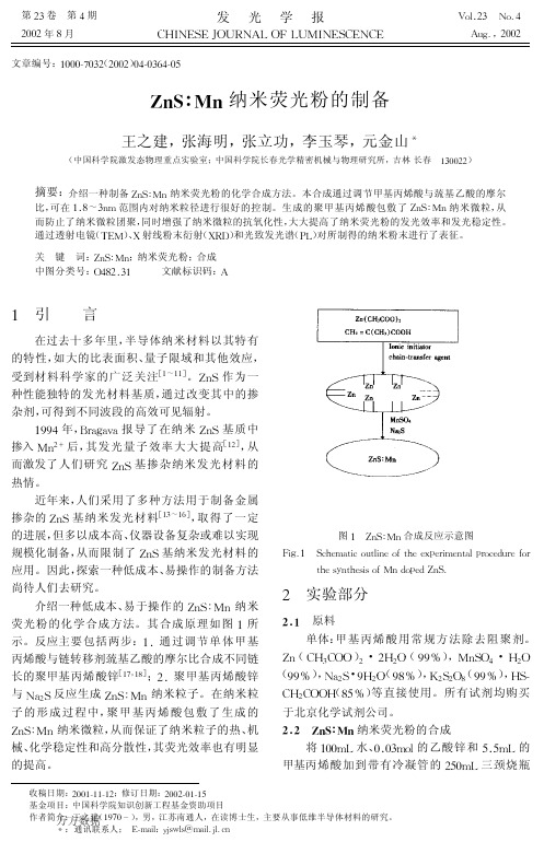
! 实验部分
&’( 原料 单体:甲 基 丙 烯 酸 用 常 规 方 法 除 去 阻 聚 剂。
84(VW5VDD)!·!W!D(&&X),;49D6·W!D (&&X),K+!9·&W!D(&=X),Y!9!D=(&&X),W9$ VW!VDDW(=%X)等直接使用。所有试剂均购买
于北京化学试剂公司。
2345$ ,67 89 +( :8;<: ’()5=>< ?8@<A-B38C89
?<B>-1AD@31-13:B8?<A1-;B8-1<B31-13:-A<!..*/ (-)-(:$..*/(0),A<C;<1B3E<@D;(1),67;-BF
B万<A(方98数A0据G@H’()*+(5
图I 室温下’()*+(的发射光谱(,-)甲基丙烯酸与 巯基乙酸的摩尔比为!..*/;(0)甲基丙烯酸与 巯基乙酸的摩尔比为$..*/;(1)体材料 ’()* +(
杂剂,可得到不同波段的高效可见辐射。
#&&6年,FG+H+I+报导了在纳米 849基质中 掺入 ;4!J 后,其发 光 量 子 效 率 大 大 提 高[#!],从 而激发了人们研究 849基掺杂纳米发光材料的 热情。
近年来,人们采用了多种方法用于制备金属
掺杂的 849 基 纳 米 发 光 材 料[#5"#7],取 得 了 一 定 的进展,但多以成本高、仪器设备复杂或难以实现
发光学报
第!$卷
"#$
"#$
!"#!!" "%%#&("#$"%%)!’( "("#!!" "%%)!’(
0W2O21纳米荧光粉的制备及其发光性质研究
0 20 30
加
2口托’)
50
60
70
豫到Eu”4厂(5 D0)组态的概率是不随掺杂浓度的变化而改 变的。所以激发谱中。一Eu cTB对比()一w cTB的相对强 度会随着Eu抖浓度的增加而增强。
n昏lⅪm
s哗晌ofE一+d叩edYmw2ql
b
帕肿坤nicl嚣n 5%and
20%
根据xRD谱通过谢勒公式计算得到样品的平均粒径约 为80 nrn。谢勒公式的具体形式见式(1)
D=觑/[(酽一届)“2cos刃
(1) j蔓扫;口8葺
式中女为值为o.9的常数,A等于o.154f1In(铜Kd辐射),口 为衍射峰数值的一半,口为衍射辟的半高宽,岛是用单晶硅 标样测得的系统增宽修正。图2(a),(b)和(c),(d)为Eu抖 掺杂浓度5%和20%的Y.。wzq.纳米晶体的扫描电镜照片, 由图2可以看出所获得样品的粒径约为80 r蚰,与计算结果 一致。
nlL
型照明系统。目前市场上最常见的是GaN基蓝光二极管搭 配YAG:Ce黄色荧光粉的白光LED【¨。但是由于这种白光 LED是使用蓝光和黄光混合产生自光,所以有色温偏低的缺 点。为了解决这一问题,学术界和工业界提出了把近紫外 LED芯片(NUv-LED)和近紫外光激发的红、绿、蓝三基色 荧光粉结合,组成白光LED系统的方案。目前这一方案的主 要技术瓶颈是缺乏合适的红色荧光粉。因此,开发能够被近 紫外光和蓝光有效激发的红色荧光粉成为一项迫切的任务。 钨酸盐材料具有良好的理化性质,被广泛应用于发光材料等 领域。特别是Eu3十掺杂的钨酸盐材料由于有潜力成为高效 近紫外激发的红色荧光粉,更被发光材料研究者们所关 注[z。5]。本课题组用沉淀法合成了Ytowz 02。:Eu荧光粉,通 过X射线衍射图谱及SEM网像对样品的结构和形貌进行表 征。用它的激发光谱和发射光谱来研究它的发光特性。在光
纳米Y_2O_3_Eu荧光粉的光致发光研究
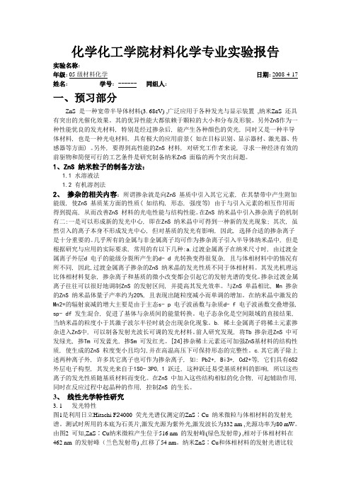
3国家自然科学基金及国家教委高校博士点基金资助项目 1997年9月9日收到纳米Y 2O 3∶Eu 荧光粉的光致发光研究3谢平波a,b ) 段昌奎a ) 张慰萍a )尹 民a,b ) 楼立人a,b ) 夏上达a,b )a )(中国科学技术大学物理系,合肥 230026)b )(中国科学院激发态物理开放研究实验室,长春 130021)摘要 报道了用燃烧法制备的系列粒径的纳米Y 2O 3∶Eu 材料,对其进行了激发光谱,发射光谱,荧光寿命等测试.结果表明,随着纳米Y 2O 3∶Eu 粒径的变化,激发光谱、发射光谱、荧光寿命都发生了明显的变化,猝灭浓度有了明显的提高.通过分析,初步揭示了纳米Y 2O 3∶Eu 的光致发光光谱随粒径变化的规律.关键词 纳米Y 2O 3∶Eu ,光致发光光谱,荧光寿命,浓度猝灭,表面效应1 引 言纳米材料由于介观效应而表现出独特的物理化学性质,如量子尺寸效应,表面效应等使纳米材料具有不同于常规固体的性能特点.但是,对纳米发光材料的研究目前一般主要限于和常规尺度的材料作对比,对于掺杂纳米发光材料的性质随粒径的变化规律研究得较少.Y 2O 3∶Eu 是性能优良的荧光粉,商用的这类荧光粉一般用高温固相法或溶液共沉淀法合成,其颗粒度一般在微米级.由于Y 2O 3∶Eu 荧光粉的广泛应用,对其纳米材料的研究是很有意义的.燃烧法合成[1],是指材料通过前驱物的燃烧而获得.在一个燃烧合成反应中,反应物达到放热反应的点火温度时,以某种方法点燃,随后反应由放出的热量维持,燃烧产物即为所需材料.燃烧的特点是快速移动的燃烧波峰(1~100mm s ),高的自发温度(1000~4000K ),该法提供了一种制备样品的独特手段,我们用燃烧法合成了一系列粒径的Y 2O 3∶Eu 纳米发光材料,测量了其光致发光性质,并对不同粒径的材料的光致发光性质进行了对比.2 样品制备和测试2.1 样品制备Y 2O 3∶Eu 样品用燃烧法合成.原料为99.99%的Y 2O 3和Eu 2O 3,分析纯的甘氨酸(Gly ).按一定比例将Y 2O 3,Eu 2O 3溶于硝酸中,将Gly 溶于蒸馏水,两者充分混合后加热蒸发水分.随着水分的减少,体系逐渐呈粘稠状,实际呈一种溶胶状态,并开始发泡.继续加热,水分基本蒸干时,温度急剧上升,达到一定温度时点燃后,自行维持燃烧,直到所有反应物反应完全,得到最终产物.其反应式如下∶第19卷 第2期发 光 学 报V o l.19,N o.21998年6月 CH I N ESE JOU RNAL O F LUM I N ESCEN CE June ,1998421 发 光 学 报第19卷6Y(NO3)3+10H2N CH2COOH+18O2→3Y2O3+20CO2+5N2+25H2O+18NO2其中Gly作为还原剂,NO3作为氧化剂,进行放热氧化2还原反应.由Gly NO3(G N)的比值,可得到一系列不同温度逐渐改变的火焰,改变火焰的温度,可制备出不同粒径的Y2O3∶Eu纳米材料,最小达5nm.通过控制初始反应物的比例,可得到不同掺杂浓度的Y2O3∶Eu纳米样品.反应产生高温,并放出大量气体,生成疏松的洁白泡沫状产物,整个燃烧过程在数十秒内完成.生成的产物无需再经过高温灼烧即可在紫外光激发下发光.2.2 测试1)样品的晶体结构和晶粒尺寸用Ph ili p s PW(1830 25)X2射线衍射仪及日本理学D m ax2r A型X2射线衍射仪测定.2)样品激发光谱的测量采用∶(1)日本日立H2850型荧光光度计,激发光源为Xe 灯;(2)Job in2Yvon M odel HR1000单色仪,配YA G∶N d3+三倍频泵浦的染料激光器为光源.3)寿命的测量以三倍频的YA G∶N d3+泵浦的染料激光器为激发光源,L eC roy 9350M示波器记录.3 结果与讨论X2射线衍射分析表明合成的样品全部为立方相的晶态Y2O3[2],其中5nm、80nm的样品和Ph ili p h s样品的结果见图1,没有杂相,其衍射峰的位置和强度与国际晶体标准衍射卡片N o.2521200基本吻合.纳米样品粒径根据衍射峰的展宽用Scheer公式估算得到.对纳米样品进行了激发光谱,发射光谱,荧光寿命和发光亮度的测定,结果表明∶1)不同粒径的Y2O3∶Eu中Eu3+发光的主要激发带是250nm左右的Eu3+电荷迁移态(CT S)吸收.此峰随粒径的减小而发生红移,粒径为80nm,40nm,10nm时,激发峰值分别位于239nm,243nm,250nm,此结果已在文献[3]中详细报导.2)监测611nm发射峰,粒径为80nm和5nm的样品的7F0→5D1的激发光谱如图2, 10nm及40nm样品的激发谱与80nm样品的基本一致,仅峰略有展宽,但5nm的样品的激发谱有明显的差别,弥散在525~529nm之间,形成一较宽的吸收带,几个强吸收峰依然存在,而相对强度发生较大改变.文献上也有一些关于纳米Y2O3∶Eu的一些结果,可能由于粒径较大而没有明显的宽带[4].另外,我们没有观察到各峰位的移动.3)不同粒径样品的发射谱如图3.通过和文献中对常规样品的研究结果[4~7]的比较,同样发现明显的变化发生在10nm以下样品上,10nm及以下的纳米样品的光谱图在5D0→7F2的跃迁的能量范围内是一个611nm的主峰和612~630nm的宽带的迭加,宽带的发射随粒径的减小而增强,在粒径为5nm时,已超过611nm发射峰.由于电子衍射实验表明5nm的样品为晶态[8],因此这种现象看来是由小粒径纳米粒子的大比例表面造成的.4)同一掺杂浓度的样品的发光亮度随尺寸的减小有所降低,如图4(样品的掺杂浓图1 各种粒径的样品的X 射线衍射谱F ig .1 X 2ray diffracti on spectra of samp lesw ith different size.图2 不同粒径样品的7F 0→5D 1的激发光谱(监测波长为611nm 的发射光谱)F ig .2 Excitati on spectra of 7F 0→5D 1of samp les w ith different diam eter by monitering611nm em issi on.图3 不同粒径样品的发射光谱 F ig .3 Em issi on spectra of samp lesw ith different diam eter.图4 同一掺杂浓度(10%mo l )的样品的发光亮度随粒径尺寸的变化F ig .4 To tal lum inescence intensity of samp les w ith different diam eter and w ith 10%of Eu in mo l.521第2期谢平波等:纳米Y 2O 3∶Eu 荧光粉的光致发光研究 图5 80nm ,10nm ,5nm 样品的衰减曲线F ig .5 Evo luti on curve of intensity of the samp le w ith 80nm ,10nm and 5nm diam eter .度为10%).同时荧光寿命缩短,图5是不同粒径(同一浓度10%)样品在室温下的衰减曲线.尺寸在10nm 以上的样品衰减曲线可以用单指数拟合.在室温下,和Ph ili p s 公司的商品Y 2O 3∶Eu 荧光粉的寿命为1.7m s相比,80、40、10nm 的样品的寿命分别为1.4m s 、1.3m s 、1.1m s ,寿命随尺寸减小明显缩短,5nm 的样品衰减更快,且无法用单指数形式拟合,用双指数可以很好地拟合,拟合结果为Σ1=0.42m s ,Σ2=1.29m s ;低温下寿命随粒径的变化情况与室温时一致,但比室温时均变长.5)纳米Y 2O 3∶Eu 中Eu 的猝灭浓度从常规Y 2O 3∶Eu 荧光粉[7]的6%有所提高,如5nm 样品为12%[3],而且发射光强随Eu浓度的变化比较平缓.如上的大部分现象可以归结为表面的影响∶1)从Eu 电子态和基质态的角度来讲,CT S 态吸收相当于电子从Y 2O 3价带能级跃迁到Eu 中心,由于表面附近的Eu 的配位不足等表面缺陷导致价带顶附近存在表面能级;从Eu 的价轨道和O 的价轨道的相互作用来讲,由于表面的氧配位不足,导致两种价轨道的相互作用造成的能级分裂减小,从而CT S 吸收发生红移.2)发射光谱和监测波长为611nm 发射峰的激发光谱中各峰(主要为5D 0→7F 2的跃迁)相对强度的改变及宽带的出现是纳米表面层中Eu 离子的环境的改变造成的.粒径越小,表面占的比例越大,因而改变越明显,如果表面层的厚度为0.5nm ,则尺度为5nm 时样品的表面层将占近50%,因而5nm 时宽带激发谱超过611nm 主发射峰是一致的.在常规样品中Eu 的两种格位分别为C 3i 和C 2,前者为电偶极禁戒跃迁,因而寿命比较长(两种格位的寿命在77K 时分别为7.8m s 和1.0m s [7]),而在纳米样品中,表面层的Eu 的对称性降低,占C 3i 格位的Eu 的电偶极宇称禁戒被解除,态间跃迁几率增大,因而可能C 3i 位峰的吸收相对有所增强,这一点也被5nm 样品激发光谱中对应于C 3i 格位吸收的526.4nm 峰相对强度的明显增强所证明.表面层占C 2格位的Eu 环境也同样有所改变,这也可能会影响到本格位各吸收峰和发射峰的相对强度,特别是三价Eu 离子的5D 0→7F 2,它的发光跃迁对环境是敏感的,这种相对强度的改变会更突出.这些环境的改变同时会影响到能级位置,导致能级有一个分布范围,从而在发射谱和激发谱上出现宽带.3)燃烧法合成的样品的表面没有经过任何人为的修饰或处理,会对发光起到一定的猝灭作用,因此随粒径的减小发光寿命缩短且发光亮度有所下降,但后者的下降幅度更大,这表明纳米样品发光亮度的降低不完全是发光能级的无辐射跃迁造成的.有部分621 发 光 学 报第19卷激发能从CT S 直接传递到表面态而猝灭,这一点不影响发光能级的寿命;纳米粒子强散射导致对紫外激发光的吸收减弱(这里涉及的不是带间跃迁,和半导体纳米粒子的因为波矢选择定则放松而导致的吸收增强不是一回事)对亮度下降也会起到一定的作用.本质上,发光衰减曲线是各个发光中心的衰减的叠加,在常规样品或尺寸较大的纳米样品中,在Eu 浓度较大的情况下,发光主要是全同的C 2位的发光(C 3i 位主要把能量传递给C 2位),因此寿命是单一的,可以用单指数衰减曲线拟合;而在5nm 的样品中,表面的原胞占了近50%的比例,这里的C 3i 位的Eu 由于环境的改变而寿命缩短,对发光的贡献增大,但它的寿命和C 2位的Eu 一般不相等,考虑环境的改变不是太大时,其辐射跃迁的寿命一般比C 2位长,用双衰减指数可以很好拟合,可能就是这个原因.另外表面占C 2位的Eu 的寿命由于同样的原因,和常规材料及纳米发光材料内部的均不同,且有一个分布,颗粒越小,此现象越明显,这也会导致发光衰减曲线不再可以用单指数来拟合.具体的机理和以上的一些分析有待进一步证实,我们拟用格位选择激发来对此作进一步研究.4)由于能量共振传递被纳米粒子的边界所阻断,激发能被传递到猝灭中心的几率减小,因而猝灭浓度增大.总之,我们用燃烧法合成了一系列粒径的Y 2O 3∶Eu ,对其CT S 态吸收、发射光谱、亮度和寿命进行了测定,理论分析表明所观测到的现象可归结为表面的影响.参 考 文 献[1]M o re J J ,Feng H J.P regress in M ater .Sci .,1995,39:243.[2]Faucher M ,Pannetier J .A cta C ryst .B ,1980,36:3209.[3]T ao Ye,Zhao Gui w en,Zhang W ei p ing et a l ,M aterials R esearch Bulletin 1997,32:501.[4]裴秩慧,刘行仁.发光学报,1996,17:52.[5]D expert 2Ghys,Faucher M.Phys .R ev .B,1979,20:10.[6]Chang N C ,Gruber J B .J .Chem .Phys .,1964,41:3227.[7]O zaw a L ,Fo rest H ,Jaffe P M et a l ,J.E lectrochem.Soc .,1971,118:42.[8]谢平波,张慰萍,尹 民等.无机材料学报,1998,13(1)(待发表).721第2期谢平波等:纳米Y 2O 3∶Eu 荧光粉的光致发光研究 821 发 光 学 报第19卷THE PREPARAT I ON OF NANOCRY STAL Y2O3∶EuB Y COM BUST I ON M ETHOD ANDITS L U M INESCENT PROPERT IESX ie P ingbo a,b) D uan Changku i a) Zhang W ei p ing a)Y in M in a,b) L ou L iren a,b) X ia Shangda a,b)a)(D ep a rt m en t of P hy sics,U n iversity of S cience and T echnology of Ch ina,H ef ei230026)b)(L abora tory of E x cited S ta te P rocesses,Ch inese A cad e my of S ciences,Chang chun130021)AbstractN anocrystal Y2O3∶Eu w ith differen t concen trati on of Eu and grain size from5nm to80nm w ere p rep ared by com bu sti on m ethod.T heir excitati on spectra,em issi on spectra,the lifeti m e and in tegral in ten sity of differen t sam p les w ere m easu red and com p ared.It is found that as the grain size decrease,the ab so rp ti on of charge tran sfer states is red2sh ifted from239to250nm,the em issi on sp ectra and excitati on spectra show a band2like structu re w ith increasing strength in additi on to the peak s as in bu lk Y2O3∶Eu m aterial,w h ich is no t resu lt from am o rphou s effect,the life ti m e of611nm em issi on decreases in the sam e m agn itude,and the quench ing concen trati on increases. T he m echan is m of these p henom enon is revealed by crude analysis.Key words nanocrystal Y2O3∶Eu,pho to lum inescence spectrum,lifeti m e,concen tra2 ti on quench ing,su rface effects R eceived9Sep tem ber1997。
Ca9Y(PO4)7∶Ce3+Tb3+纳米荧光粉的制备及发光性能
d e t a i l .T h e r e s u l t i n d i c a t e s t h a t t h e l u m i n e s c e n c e c o l o r o f C a 9 Y ( P 0 4 ) 7 : T b c a n b e t u n e d t h r o u g h a d j u s t i n g t h e
T b 之 间最 大 的 能 量传 递 效 率 为 5 5 . 6 %。 C a 9 Y ( P 0 4 ) : C e , T b “ 的 发光 颜 色 可 以 通 过 激 活离 子 之 间 的 能 量传 递 和共 发 射 得 到 可控 调
节 。S E M 分 析 表 明荧 光 粉 颗 粒 尺 寸 在 1 0 0 n m左右 , 分散性好 。
关键词 : C a g Y( P 0 4 ) 7 : C e “ , T b ; 水热 法 ; 交叉 驰豫 ; 能量 传 递 中 图分 类 号 : 0 4 8 2 . 3 1 文献标识码 : A 文章 编 号 :1 0 0 1 — 4 8 6 1 ( 2 0 1 6 ) 1 2 — 2 1 3 6 — 0 7
c o nc e n t r a t i o n o f Tb ¨ .wh i c h i s a t t r i bu t e d t o t h e e n e r g y c r o s s r e l a x a t i o n o f Tb ¨ .And t h e e n e r g y t r a ns f e r
W ANG Z a n MI Xi a o — Yu n XI E L i n g - J i e P AN Xi a o - Yi n g
ZHOU Ho n g - - Ya n CHEN S h u- - Yi ZHANG Xi - - Ya n BAI Zh a o ・ - Hu i
Cu2+纳米ZnS荧光粉的制备及发光特性研究
化学化工学院材料化学专业实验报告实验名称:年级:05级材料化学日期:2008-4-17 姓名:学号:------同组人:一、预习部分ZnS 是一种宽带半导体材料(3. 68eV) ,广泛应用于各种发光与显示装置,纳米ZnS 还具有突出的光催化效果。
其的优异性能大都依赖于颗粒的大小和分布及形貌。
另外ZnS作为一种性能优良的发光材料, 特别是经过掺杂后, 能产生各种颜色的荧光, 同时又是一种半导体材料, 也是一种光电材料, 具有极大的应用前景( 如在目标识别、显示器材、激光器、传感器等方面) 。
另外, 要得到高性能的ZnS 材料, 对研究工作者来说, 寻求一种经济有效的前驱物和简便可行的工艺条件是研究制备纳米ZnS 面临的两个突出问题。
1、ZnS 纳米粒子的制备方法:1.1 水溶液法1.2 有机溶剂法2、掺杂的相关内容:所谓掺杂就是向ZnS 基质中引入其它元素, 在其禁带中产生附加能级, 使ZnS 基质某方面的性质( 如结构, 形态, 强度等) 由于与引入元素的相互作用而得到提高, 从而改善ZnS 材料的光电性能与结构性能。
在ZnS 纳米晶中引入掺杂离子的机制有二:一是可以形成新的发光中心, 即在ZnS 纳米晶中可得到一种新的发光现象; 其次, 虽然引入的离子本身不形成发光中心, 但对基质的发光有影响, 因此, 选择合适的掺杂离子是十分重要的。
几乎所有的金属与非金属离子均可作为掺杂离子引入半导体纳米晶中, 但是根据研究与应用的实际要求, 常用的有以下几种:a.过渡金属离子在纳米尺寸时, 由过渡金属离子外层d 电子的能级分裂所产生的d- d 光转换变得很复杂, 且与体相材料中的情况有所不同, 因此,过渡金属离子掺杂的ZnS 纳米晶的发光性质不同于体相材料。
其发光机理远比体相材料复杂, 掺杂离子和基质的微小改变都会引起它的发射光谱的变化。
掺杂过渡金属离子往往可以很好地调制ZnS 的发射区间, 并提高其发光效率。
纳米红色长余辉发光材料的合成及其发光特性
S y n t h e s i s a n d Lu mi n e s c e n t Pr o p e r t i e s
CHEN Z u a n y u, L I We n y u
( F a c u l t y o f E c o l o g y , L i s h u i U n i v e r s i t y , I j s h u i 3 2 3 0 0 0 , Z h e j i a n g )
h i g h t e mp e r a t u r e s o l i d p h a s e c a l c i n a t i o n m e t h o d , u s i n g Y 2 0 3 , Mg ( O H) 2 ’ 4 Mg C O , 6 H2 O, E u 2 0 3 ,T i O 2 ,E D T A
摘要 : 以Y 2 O 3 、 Mg ( O H) 2 ・ 4 Mg C O 3 ・ 6 H 2 O、 E u 2 O 3 、 T i O 2 、 E D T A( C l o Hl 6 N 2 O 8 ) 、 浓硝 酸为 主要 原料 , 采 用
溶胶 一凝胶 高温 固相 煅烧 法合 成 了纳米 Y O 2 S : E u , M , T i “红 色长余 辉发 光材料 。 采 用 x射 线衍射
呈现 纯正红 色发 光 。硫 化 温度 为 1 0 0 0 时, 样 品的余辉 时间为 6 0 m i n 。
关 键词 : 红 色长余 辉 ; 纳米 晶 ; 溶胶 凝胶 法 ; 发光 性 能 d o i : 1 0 . 3 9 6 9  ̄ . i s s n . 2 0 9 5 - 3 8 0 1 . 2 0 1 7 . 0 2 . 0 0 7
长余辉荧光粉在光催化系统中的应用研究进展
Vol.412020年11月No.112404~2414CHEMICAL JOURNAL OF CHINESE UNIVERSITIES 高等学校化学学报长余辉荧光粉在光催化系统中的应用研究进展苏高鸣,沈瑞晨,谈洁,袁荃(湖南大学化学与化工学院化学生物学与纳米医学研究所,化学生物传感与计量学国家重点实验室,长沙410082)摘要长余辉荧光粉是一种新兴的有广泛应用前景的发光材料,在停止激发后仍可保持发光.近年来,具有独特光学性质的长余辉荧光粉得到了发展,其在光催化领域的应用也得到了广泛的研究.长余辉材料具有脱离光源的特点,可以有效地在黑暗环境中推动光催化反应的进行;同时,长余辉荧光粉的超长发光寿命使其在长时催化体系中占有重要地位,使全天候光催化成为可能.简单来说,长余辉荧光粉被证明是一种新出现的功能材料,在光催化方面具有前所未有的优势.本综述总结了长余辉荧光粉在污染物降解、杀菌消毒和高效制氢领域中应用的最新进展.关键词长余辉荧光粉;光催化;应用中图分类号O643.36;O644.17文献标志码A Progress on the Application of Long Persistent Phosphors inPhotocatalytic SystemSU Gaoming ,SHEN Ruichen ,TAN Jie *,YUAN Quan *(Institute of Chemical Biology and Nanomedicine (ICBN ),State Key Laboratory of Chemo/Biosensing and Chemometrics ,College of Chemistry and Chemical Engineering ,Hunan University ,Changsha 410082,China )Abstract Long persistent phosphor is a new and promising luminescent material ,which can maintain lumi‐nescence after stopping excitation.In the past few years ,long persistent phosphors with unique optical proper‐ties have been developed and their applications in the field of photocatalysis have been widely studied.Owing to the characteristic of leaving the light source ,long persistent luminescence can effectively promote the photo‐catalytic reaction in the dark environment.Meanwhile ,long persistent phosphor has an important position in the long -time catalytic system due to its long luminous life ,which makes round -the -clock photocatalysis possi‐ble.In brief ,long persistent phosphors have been proved to be a new functional material with unprecedented advantages in photocatalysis.In this review ,we summarize the latest advances in the application of long persis‐tent phosphors in the degradation of pollutants ,sterilization ,and efficient hydrogen production.KeywordsLong persistent phosphor ;Photocatalysis ;Applicationdoi :10.7503/cjcu20200411[综合评述]收稿日期:2020-07-01.网络出版日期:2020-09-29.基金项目:湖南省自然科学基金(批准号:2020JJ4173,2020JJ5038)、湖南省科技创新计划项目(批准号:2018RS3060)和长沙市科技计划项目(批准号:kq1901030)资助.联系人简介:袁荃,女,博士,教授,主要从事纳米功能材料研究.E -mail:****************.cn 谈洁,女,博士,副教授,主要从事纳米功能材料研究.E -mail:*****************.cn2405 No.11苏高鸣等:长余辉荧光粉在光催化系统中的应用研究进展1IntroductionLong persistent phosphor(LPP)is a class of substances that can absorb solar energy and continue to glow for seconds to days after the excitation stops[1—3].For nearly a thousand years,human beings have never stopped exploring it.According to ancient Chinese legend,the night pearl formed by natural minerals is regarded as a priceless treasure[3,4].In the early17th century,Italian alchemists discovered Bologna stone,which became the first detailed documentation of LPPs.Until1866,French scientist Sidot first completed the preparation of ZnS∶Cu,the LPP gradually faded its mysterious veil and began to attract extensive attention from scientists[5].In1996,Matsuzawa et al.[2]discovered the famous phosphor SrAl2O4∶Eu2+,Dy3+,which can provide bright green light emission within a few hours after the stoppage of excitation,becoming an important milestone in the development of long-persistent materials.SrAl2O4∶Eu2+,Dy3+has a longer afterglow lifetime and higher luminescence intensity than commercial ZnS∶Cu2+,Co2+materials during the same period.This encouraging finding received a lot of attention,and many researchers began looking for phosphors that emit different colors of light and last longer time.Since then,many LPPs have been developed and widely used in emergency lighting,luminous coatings,instrument display and other fields[6—10].With the in-depth study of the long afterglow phenomenon and the rapid development of long persistent phosphor,its application areas have also been expanded[11—16].In recent years,LPPs have shown unpreceden-ted advantages in the field of photocatalysis due to their long luminous life and luminescence without light sources.The basic process of photocatalysis,simply put,is that under the irradiation of light,photocatalytic materials produce photo-induced electron-hole pairs,and then these electrons or holes are migrated to the sur‐face of the material for further redox reactions,thus achieving the purpose of purifying pollutants,material synthesis,and solar energy transformation[17,18].According to this principle,photocatalysts cannot work con‐tinuously without the illumination of light source.However,the alternation of day and night due to the rotation of the Earth makes the sunlight cannot meet the requirements of round-the-clock photocatalysis,which be‐comes one of the main problems that limit the industrial application of photocatalytic technology.Therefore,the combination of long persistent materials and semiconductor catalysts to build a round-the-clock photocata‐lytic system became an attractive solution[19].At present,the research on LPP photocatalysis is still in the initial stage.In2004,Zhang et al.[20]first proposed the definition of LPP photocatalysis.They coated Sr4Al14O25∶Nd,Eu phosphors onto TiO2catalyst to build a multilayer massive LPP-catalyst composite,which successfully realized the photodegradation of Rhoda‐mine B under dark conditions created by removal of the light source.Since then,although many articles have been continuously reported on the mechanism of photocatalysis[21—25]and the synthesis of long persistent materials[26—36],few have combined long persistent materials with photocatalysis.Therefore,the purpose of this review is to summarize the specific applications of long-persistent materials in the field of photocatalysis,to analyze the important role and unique advantages of long-persistent materials in round-the-clock photocataly‐sis systems,and to propose possible solutions and prospects based on the existing problems in the current de‐velopment.2Mechanism of Persistent Luminescence and Its Role in Photocatalysis To better understand the long afterglow phenomenon and its application in photocatalysis,it is necessary to briefly introduce its luminescence mechanism.At present,the mechanism of electron retention in long per‐sistence luminescence is still controversial,which can be found in some previously published works[1,3,37]. This section only introduces the general concept of long persistence luminescence.It is generally believed thatVol.41高等学校化学学报the generation of the long afterglow is related to two types of active centers in LPP :traps and emitters.In LPPs ,traps are usually their intrinsic crystal defects or formed by co -doped ions.The material containing traps is also known as the host ,and the doped ions are also called activators.The energy of the trap is usually a few electron volts (eV )lower than the conduction band of the host material.The emitters are usually lantha‐nide or transition metal ions.The formation of persistent luminescence involves four successive steps ,which are the generation ,capture ,release and recombination of carriers ,respectively [38].Qiu et al .[39]made a sim‐ple description of the above four processes ,as shown in Fig.1.Charge carriers such as electrons and holes are created when effectively excited (electron beams ,X -rays ,and ultraviolet light ).These charge carriers are then captured by traps in the crystal ,where they can be stored for a long time.The above process is called optical charging.When stimulated by heat or light ,the captured charge carriers escape from the trap andrecombine with the emitter to produce what is known as persistent luminescence.In essence ,LPP is not only a luminescent material but also an electron storage material (ESM )[40].This electron storage material is key to starting a catalytic reaction under dark condi‐tions.Coupling of LPP with photocatalyst pro‐vides a storage place for photogenerated charge carriers so that they will not be consumed only by redox reactions that occur on the catalyst sur‐face.In the dark environment ,electrons and holes stored in the LPP can directly enter the electrolyte solutions to exert their catalytic activity via an anodic or cathodic reaction [19].Or excite the emitter ions through recombination ,releasing energy in the form of light ,acting as a source of light for catalytic reactions [41—45].For example ,Zhou et al .[46]proposed the afterglow mechanism in the Sr 2MgSi 2O 7∶(Eu ,Dy )/g -C 3N 4system.Specifically explaining ,when the sunlight illuminated on the phosphor ,its charge energy is transferred to the 4f 7energy level of Eu 2+.Excited by this energy ,Eu 2+is subsequently migrated from ground state to the 4f 65d energy level situated in the conduction band ,where Eu 2+continues to self -ionize and turns in‐to Eu 3+accompanied by the separation of free electrons.Dy 3+captures the electron and changes into Dy 2+,whose ground state is lower than the conduction band.As soon as the irradiation is cut off ,the electron would be transferred back to the conduction band from Dy 2+and then recombined with Eu 3+,causing an emission from 5d to 4f as a result of thermal activation.Electrons and holes are created soon after the g -C 3N 4is excited by the fluorescence ,and these carriers then migrated to the catalyst surface to form ·OH and ·O −2through reaction with H 2O and O 2.This luminescence assist system can be used for LPP photocatalysis during the day and at night and can be extended to other fields.3Application of LPP Photocatalysis in Degradation of Organic PollutantsOrganic pollutants mainly refer to artificial additives ,dyes ,pesticides and other substances produced during food processing ,textile printing ,dyeing and agricultural production.So far ,methods including adsorption [47,48],filtration [49],biodegradation [50],chemical catalysis [51]and photocatalysis [52,53]have been suc‐cessfully developed and applied to organic pollutant treatment.Among these methods ,photocatalytic degrada‐tion is considered as a new environmental protection technology with good development prospects because of its simple process ,easy control of operating conditions ,stable and easy obtain of photocatalytic materials ,low energy consumption and no secondary pollution.However ,three major problems hinder thecomprehensive Fig.1Brief description of the luminescence mecha⁃nism of LPP [39]Copyright 2014,Springer Nature.24062407 No.11苏高鸣等:长余辉荧光粉在光催化系统中的应用研究进展industrialization of photocatalysis.Firstly,the photocatalytic reaction cannot be carried out in the dark due to the lack of light source which can excite the semiconductor[46,54].Secondly,due to the light-shielding effect of the solutions[55],particularly in the polluted water body,the light utilization efficiency is low,which means the photocatalyst cannot be fully activated by sunlight.Hence,the formation of photoelectron-hole pair is re‐duced,which leads to low photodegradation efficiency[56—58].The last restriction is the unideal performance of photocatalysts.Although extensive studies has been made on TiO2due to its cheapness,nontoxicity,and sta‐ble optical properties,the practical application is still limited because of its inefficient quantum yield and narrow light response range[59,60].Recently,some efforts have been made to achieve photocatalytic degradation in wastewater with high cata‐lyst concentration.Zhou et al.[61]prepared Zn2SiO4∶Ga3+single-phase materials with persistent luminescence and catalytic properties by the sol-gel method.With Zn2SiO4as the host,in which only Ga3+ion is doped to re‐place Zn2+and form an energy trap GaZn+with positive charge to capture photoinduced electrons and slow down the release process of trapped electrons,thus extending the afterglow lifetime to several minutes.The synthe‐sized Zn2SiO4:Ga3+has UV afterglow characteristics,emitting a wide fluorescence range from320nm to650 nm under254nm excitations,with UV peaks at362nm,and the remaining glow signals can remain high in‐tensity for5minutes,even can be observed directly with the naked eye in the dark.The total organic carbon (TOC)removal rate of permethrin solution treated with this material was as high as97%within two hours of UV irradiation,which was significantly superior to28%of the Zn2SiO4in the blank control group.Considering that Zn2SiO4has been commercialized at low cost,this persistent catalyst will be an ideal material for desig-ning novel photocatalytic reactors at high catalyst concentrations.Wu et al.[62]hybridized silicate-based melilite-type LPP Sr2MgSi2O7∶Eu2+,Dy3+with a common visible-light-excited photocatalyst,silver orthophosphate(Ag3PO4)(Fig.2).Structural characterization showed that the spherical Ag3PO4nanocrystals in the composites were highly scattered and localized on the tetragonal LPP surface,forming a heterojunction capable of changing the electron transfer behavior(inhibiting carrier recombi‐nation),which greatly enhanced the photoactivity of the photocatalyst when externally excited by sunlight and demonstrated long afterglow-driven persistent photocatalysis after shutting down the irradiation.The photodeg‐radation reaction rate constant of M15A1(the subscript numbers refers to the ratios of phosphors to catalysts)was0.42under solar and visible light irradiation,while it was only0.17for Ag3PO4itself.After turning off the light source,the photodegradation of methyl orange(MO)by the composite could continue in the dark,driving further decomposition of about32%of the residual MO in20min.Lu et al.[63]added the external rotating disk as the auxiliary to further improve the afterglow lifetime and catalytic activity based on the above two methods.The combination of Cu2O nanocrystals(NCs)with core-shell structured M-TiO2and the incorporation of SrAl2O4∶(Eu,Dy)phosphors enhances the interaction between pho‐tons and catalysts by the multiple reflection and scattering of light in M-TiO2,thus enhancing the2-Cu2O NCs/M-TiO2light absorption;Meanwhile,the p-n heterojunction between Cu2O and TiO2remarkably inhibits the recombination of electron-hole pairs and is beneficial to capture the photogenerated carriers more effective‐ly.By revolving the catalyst disk,a continuously refreshed slim layer of water film is shaped on the surface of the reactor.The propagation distance of photons in the film is notably shortened,which makes it less easy for the light to be absorbed by the solution,thus improving the light utilization efficiency of the photocatalytic sys‐tem.LPPs can store excess light energy and produce persistent fluorescence.The composite is excited in the dark so that it remains catalytic for3h after removing the light source.The Cu2O NCs/M-TiO2rotating disk re‐actor incorporating LPPs can achieve round-the-clock photocatalytic degradation of Bisphenol-A and Rhoda‐mine B.Vol.41高等学校化学学报4Application of LPP Photocatalysis in Disinfection and SterilizationIn the process of seawater desalination ,the accumulation of bacteria and microorganisms on the surface of the filter membrane is often the main cause of energy consumption and biological pollution [64,65].Pre -sterilized treatment can effectively decrease energy consumption and control biological pollution.However ,conventional chemical disinfectants such as hypochlorite may destroy the filter membrane ,reduce its life ,thus increase the desalination cost [66].By contrast ,the use of pure physical ultraviolet light to kill bacteria and microorganisms has obvious advantages [67].There are three bands of ultraviolet light ,in which the UV -C band with a wavelength between 200—275nm ,also called short -wave sterilized UV light ,can destroy the molecu‐lar structure of microorganisms deoxyribonucleic acid (DNA )or ribonucleic acid (RNA )so that bacteria will die or cannot reproduce ,thus achieving the purpose of sterilization.Along with the invention of semiconductor light -emitting diode ,UVC LED gradually replaced the mercury lamp and became the representative of modern new disinfection technology ,among which phosphors also played an important role [68].Phosphors in the UVC LED are usually based on the principle of upconversion ,which adjusts the visible light to the UVC band ,thus making its effort in disinfection and sterilization.However ,most of the long persistent phosphors found so far are only in the visible and near -infrared regions [69—71],while there are only less than 20long afterglow materialswith ultraviolet luminescence [72—76].In recent years ,scientists are constantly looking for UVC LPPs and deve -loping their applications in disinfection and sterilization.Yang et al.[77]chose the CS 2NaYF 6as host (Fig.3).The wide bandgap characteristics of thismaterial Fig.2Degradation of methyl orange using Sr 2MgSi 2O 7:Eu 2+,Dy 3+LLP ⁃Ag 3PO 4composites during thephotocatalytic time process,in which the simulated sunlight(●,▲)and visible light(○,△)were firstlyused for illumination,followed by the removal of light source(A),the MO concentration⁃time curvesof A(▲,△)and M15A1(●,○)in illumination stage(B)and long afterglow stage(C),where M15A1refers to a mass ratio of LPP/Ag 3PO 4=15,bar graph of the degradation efficiency during the wholephotocatalytic process,where the blue bar and red bar represent the illumination and long persistentstage,respectively(D)[62]Copyright 2017,Royal Society of Chemistry.2408No.11苏高鸣等:长余辉荧光粉在光催化系统中的应用研究进展make it easy to form defects and capture electrons.Pr 3+ion is a suitable choice of emitter for the reason that Pr 3+ions can release UVC light when a transition occurs between 4f 5d and 4f 2.By combining the above two materials ,they synthesize micron -sized LPPs with a nominal composition of Cs 2NaY (1−x )F 6∶x Pr 3+using the solid -phase method.The phosphor exhibits a strong ,persistent UVC emission peak near 250nm after X -rayirradiation ,and its signal intensity can be maintained within 2h and still significantly stand above the back‐ground interference.Their study on the LPP structure shows that this UVC LPP has a variety of traps ,which can not only release shallow electrons at room temperature but also release a great number of electrons con‐fined to deep traps by laser irradiation with different energies.The different defect levels may originate from the introduction of oxygen in the Cs 2NaYF 6lattice ,thus creating a variety of oxygen ,fluorine anion vacancies that enable them to catch and store massive amounts of electrons under X -ray irradiation and improve catalytic activity.Three defect models are envisaged as theoretical explanations.To demonstrate this concept ,they tested the inactivation of pseudomonas aeruginosa (PAO1)by this UVC phosphor at different irradiation times.The viability of P.aeruginosa PAO1was only 39.6%after 16min of X -ray irradiation ,confirming its bacteri‐cidal ability.Li et al .[78]proposed a computational approach called topochemistry to replace the experimental attempt and guide the synthesis of UVC LPPs through in -depth studies of LPP defects (Fig.4).By using first -princi‐ples density functional theory (DFT ),they first calculated the formation energies of the various defects to dis‐cuss their possibility of becoming afterglow traps.They further evaluate the ability of traps to capture carriers by calculating the correspondent charge transfer levels for different defects under thermal activation.The results show that the introduction of composited vacancies and complicated defects contribute to the generation of superficial traps relating to valence and conduction bands.To test this hypothesis ,they synthesized La (1-x )PO 4∶x Pr3+with high -density oxygen and phosphorus vacancies by a solid -state reaction.After 600s of exposure under X -ray irradiation ,the phosphors indeed exhibited more than 2h of UVC afterglow emission Fig.3Sterilization effect of UVC⁃LPP series on P.aeruginosa PAO1[77]Confocal micrograph of the blank control group(A)and four LPPs inactivated PAO1with different X -ray irradiation times of 2min(B),5min(C),10min(D),and 16min(E),where the green and red colors refer to the live and dead cells.(F)The relation curve between the time that LPPs exposure to X -ray irradiation and the corresponding survival ratios of PAO1,where 100%refers to the viability of PAO1under natural conditions.Copyright 2018,Springer Nature.2409Vol.41高等学校化学学报with a maximum emission value of 231nm.By using CaH 2as an oxygenator to create more shadow traps in Pr 3+doped LaPO 4,they optimized the afterglow intensity of phosphors and proposed an afterglow mechanism based on defect concentration and free radical participation.Specifically ,the ESR spectrum shows that there are a large number of [PO 2]·2-radicals in the monoclinic LaPO 4crystals ,which are obtained from the separation of two coordination oxygen atoms from [PO 4]structure units.X -ray photons can interact with lattice atoms in the [PO 2]·2-radical ,from where the high -energy electrons are ejected ,accompanied by the formation of [PO 2]·0radicals ,O ·-radicals and holes.And these generated charge carriers are then captured by oxygen divacancies in the lattice.Since the charge transfer level of oxygen is near the conduction band ,the trapped electrons mayescape from the traps and enter the conduction band at room temperature.Meanwhile ,the holes can be cou‐pled with Pr 3+ions.When the separated electrons drop to the 5d band of Pr 3+ions ,the ions are excited to un‐dergo transitions ,resulting in the generation of UVC afterglows.This topological chemistry -based research method may provide theoretical guidance for the future discovery of new LPPs.5Application of LPP Photocatalysis in Efficient Hydrogen ProductionHydrogen is a kind of promising clean energy with high calorific value and renewable characteristics ,which is extensively utilized in the field of industrial production and transportation [79].Hydrogen fuel cells can convert chemical energy from hydrogen and oxygen directly into electricity without any pollutant emissions ,which is an ideal power supply for new energy vehicles [80].However ,hydrogen is inflammable and easy to ex‐plode.Besides ,hydrogen atoms have a strong void effect ,which makes it easy for them to infiltrate the metal crystal lattice ,resulting in hydrogen embrittlement [81].Hence ,it is still a problem for hydrogen to store and transport safely.One efficient approach to work out this problem is to produce hydrogen on -site.However ,hy‐drogen is mostly produced at high temperatures by hydrocarbon pyrolysis or water -gas shift (WGS )reactions ,these processes require plenty of exterior heat.Field hydrogen production is still demanding.Photocatalysis can not only meet the requirement of field hydrogen generation ,but also solve the related energy -economic problems.However ,the highest solar -to -hydrogen (STH )conversion efficiency for particulate photocatalystsystems does not exceed 5%so far ,which is still much less than the expected industrial standards of 10%[82,83].Another limiting factor for the actual application of photocatalysis technology is that optoelectronic Fig.4Schematic sketch of the afterglow mechanism of Pr 3+doped LaPO 4based on defect concentrationand free radical participation [78](A )ESR spectra and 24h decay of the Ca -144h sample with and without X -ray irradiation ,where 144h means treated under 500℃for 144h.(B )Diagrammatic sketch of the radical implicated afterglow mechanism.The electron transitions are representedas black solid arrows.The electron and hole trap states are described as gray rectangles.The optical transitions of red ,blue andUVC emissions are expressed as red ,blue and purple arrows ,respectively.Copyright 2020,John Wiley and Sons.2410No.11苏高鸣等:长余辉荧光粉在光催化系统中的应用研究进展materials or equipment without energy storage devices are not able to work under dark conditions.Fortunate‐ly,LPPs offer a new way to overcome these restrictions.Cui et al.[84]directly applied the long persistent material to photocatalytic hydrogen production and achieve a5.18%theoretical STH conversion(Fig.5).They synthesized a micrometer-sized brick-shaped Sr2MgSi2O7∶Eu2+,Dy3+material by the sol-gel method.The doped Eu2+and Dy3+ions occupy the Sr2+center of the Sr2MgSi2O7,causing lattice distortion of the Sr2MgSi2O7matrix and producing a large number of surface de‐fects.The existence of these lattice defects is generally considered to be beneficial to improve photocatalytic activity.The synthesized long persistent material exhibited long afterglow emission under UV excitation,with the strongest signal peak at465nm.After15min of UV irradiation,the hydrogen production accumulated continuously within8h and reached264μmol/g,with an STH conversion efficiency of0.39%.Unique carri‐er migration pathways also contribute to its excellent photocatalytic hydrogen evolution performance.To be more specific,the excited carrier migration pathway is shown in Fig.6.The electrons of Eu2+are firstly excited from the ground-state4f to the5d level,where they are further excited by thermal energy and migrate to the conduction band(CB)of the host material Sr2MgSi2O7.Hence,Eu2+changes into Eu3+and the excited elec‐trons in CB will be captured by Dy3+,accompanied by the formation of Dy2+.In the process of photocatalytic re‐action under illumination,the majority of excited Eu2+electrons in CB can directly react with the substrates,while the unconsumed ones can keep on transferring.These transferred electrons will then be captured and stored by Dy3+ions temporarily,resulting in a longer carrier lifetime and improved catalytic efficiency in light conditions.Liu et al.[85]used g-C3N4@Au@SrAl2O4∶Eu2+,Dy3+composites as an efficient plasmonic photocatalyst to realize environmental purification and hydrogen production simultaneously(Fig.6).They firstly embedded Au nanoparticles into g-C3N4by Pechini-type sol-gel process,and then mechanically coated g-C3N4@Au compo-sites on the surface of SrAl2O4∶Eu2+,Dy3+long persistent phosphors under high-temperature calcinationFig.5Diagrammatic sketch of the mechanism of Sr2MgSi2O7∶Eu2+,Dy3+participated in thephotocatalysis process[84](A)Simple description of energy levels and photoinduced electron transfer processes.(B)—(D)XPS spectra of Eu3d,Dy3d and Dy4d to demonstrate their behavior throughout the photocatalysis process.Copyright2019,John Wiley and Sons.2411Vol.41高等学校化学学报conditions to obtain the g -C 3N 4@Au@SrAl 2O 4∶Eu 2+,Dy 3+composites.Because nanoparticles of noble metals such as Au have strong photo -material interaction properties [86].Local surface plasmon resonance(LSPR )phe‐nomenon occurs when g -C 3N 4@Au plasmonic photocatalyst composites interact with photons that match the sur‐face valence electron collective oscillation frequency.At this point ,strong electromagnetic fields and high energy carriers of a high concentration will be generated on the surface of g -C 3N 4@Au nanostructures.Owing to the continuous and effective supply of high -energy carriers under LSPR excitation ,direct transfer of positive and negative charges occurs between the plasma noble metal nanoparticles and the original photocatalyst at the interface ,thus the g -C 3N 4pristine photocatalysts will have significant photocatalytic activity for hydrogen pro‐duction.Moreover ,the additional local electromagnetic field formed in the composites promotes the forma‐tion ,migration ,and separation of photogenerated carriers ,thus obviously improves the photocatalytic efficien‐cy of the composite.This process is called the near -field electromagnetic effect.In combination with SrAl 2O 4∶Eu 2+,Dy 3+long persistent phosphors ,the g -C 3N 4@Au@SrAl 2O 4:Eu 2+,Dy 3+composite can maintain the catalytic activity for about 3h after the excitation light source (visible light )is turned off and continues to produce about 3μmol of hydrogen.6Conclusions and ProspectsPersistent phosphor is a new luminescent material with electron storage capacity ,which has attracted wide attention in the field of photocatalysis.In this review ,we discuss the application of long afterglow phos‐phors in organic degradation ,sterilization ,and catalytic hydrogen production.Persistent phosphors have spe‐cial advantages in round -the -clock photocatalysis because it does not require the aid of an external light source.And due to its long decay time ,it can maintain a long photocatalytic activity once it is charged.In the past few years ,different kinds of long persistent phosphors have been rationally designed to improve the sus‐tained luminescence intensity and increase the decay time for better photocatalytic performance.Although great progress has been made ,the application of long persistent phosphors in sterilization and hydrogen production is still in its infancy.At the present stage ,long persistent phosphors for hydrogen production still face the problems of low optical conversion rate and short carrier life ,so it is very important to develop composites with wide spectral utilization range and deep trap level.Meanwhile ,the high -efficiency photocatalytic strategy and method based on long persistent phosphors need to be developed ,and more prog‐ress of long persistent phosphors in hydrogen production is still worth looking forward to.Also ,for UV long persistent phosphors applied in sterilization and disinfection ,there are still several problems to be solved :(1)Fig.6Comparison of hydrogen generation process of the pristine g ⁃C 3N 4,SrAl 2O 4:Eu 2+,Dy 3+LPP,SrAl 2O 4:Eu 2+,Dy 3+@Au,g⁃C 3N 4@Au,g⁃C 3N 4@SrAl 2O 4:Eu 2+,Dy 3+,and g⁃C 3N 4@Au@SrAl 2O 4:Eu 2+,Dy 3+composites(A),comparison of hydrogen generation process of g⁃C 3N 4@Au@xSrAl 2O 4:Eu 2+,Dy 3+composites with different mass fractions(B)[85]Copyright 2019,Royal Society of Chemistry.2412。
荧光的余晖原理

荧光的余晖原理荧光的余晖原理是指当光源照射物体时,物体吸收光的能量后,部分能量被转化为热能,而另一部分能量则被激发并发出光,形成荧光效应。
荧光的余晖是指当光源熄灭后,物体仍能持续发出荧光的现象。
下面将从荧光的激发机制、能量转化以及荧光的持续时间等多个方面进行阐述。
首先,荧光的激发机制主要有两种:亚稳态跃迁和外电场激发。
亚稳态跃迁是指当物体受到能量激发后,电子从基态跃迁到亚稳态,然后在较短的时间内再跃迁回基态,发出荧光。
这种激发过程中,物体的能级结构起到了重要的作用。
其次,荧光的产生是通过能量转化来实现的。
光源照射物体时,物体的电子受到能量激发,从基态跃迁到亚稳态,形成激发态。
在亚稳态的存在下,电子维持在高能级上,此时电子具有较高的能量,这部分能量可以通过非辐射跃迁或辐射跃迁的方式进行转化。
非辐射跃迁是指电子从亚稳态返回基态时,能量转化为热能的过程。
在这个过程中,电子会通过与周围环境的分子或晶格相互作用,将剩余能量以热的形式释放出来。
这也是为什么荧光物体在照明光源熄灭后,仍能发出一段时间荧光的原因之一。
辐射跃迁是指电子从亚稳态返回基态时,能量以光的形式释放出来。
这是荧光物体发出荧光的直接原因,也是荧光的余晖的来源之一。
辐射跃迁过程中,电子会发出一定波长的光,形成荧光。
荧光的波长与被激发物质的能级结构和分子结构有关。
荧光的持续时间是指荧光物体在光源熄灭后,仍能持续发出荧光的时间。
荧光的持续时间取决于荧光物质的特性以及激发光的强度和波长等因素。
当激发光的强度越大或者激发光的波长越接近荧光峰值波长时,荧光物体的持续时间会相应延长。
此外,荧光的余晖还与荧光物体的材料特性有关。
不同的材料有不同的荧光特性,包括荧光的发射波长、发射强度、荧光峰值等。
一些材料具有长余晖的特性,即荧光持续时间比较长,而一些材料的荧光会很快消散。
在实际应用中,人们经常运用荧光的余晖原理来制造计时、标记和照明等产品。
比如荧光墨水和荧光粉末等物质,其主要成分往往是含有荧光剂的化合物。
无机功能材料长余辉发光材料

5、长余辉发光材料旳制备
5.1 高温固相合成法 5.2溶胶-凝胶( So-l gel) 法 5.3水热合成法 5.4燃烧法 5.5共沉淀法 ……
发光原理
定义:在阳光和紫外线照射停止后仍能发 光,并具有较长余辉时间旳材料。
基本发光原理是:
①在材料制备旳过程中,掺杂旳元素在基质中形成发 光中心和陷阱中心,当受到外界光激发时,发光中心 旳基态电子跃迁到激发态,当这些电子从激发态跃迁 回基态时,形成发光。
②某些电子在受激时落入陷阱中心被束缚光照撤除后 , 受环境温度旳扰动,束缚于陷阱旳电子跳出陷阱落到 基态,释放旳能量激发发光中心形成发光。
发光过程:光致释光或热释光
1、发光原理
激发停止后发光旳余晖(afterglow)衰减到0.032mcd/m2 (该值是人眼暗适应条件下视觉敏捷阀旳100倍)所需 要旳时间。
·发光旳衰减有赖于电子进入导带后旳行为 ·陷阱在发光旳弛豫过程中起非常主要旳作用
—俘获电子 —热骚动旳作用下放出电子 —可能同步存在多种陷阱 —发光旳衰减是多种衰减过程旳总和
长余辉发光材料
luminescent materials with long afterglow
长余辉发光材料
定义:在阳光和紫外线照射停止后仍能发 光,并具有较长余辉时间旳材料。
又称蓄光材料或夜光材料;内含能量陷阱, 涉及 ZnS 、SrAl2O4中掺有Eu2+ 、Ce3+、 Dy3+、Ag+发光
ห้องสมุดไป่ตู้
x射线长余辉 氟化物纳米晶 紫外长余辉

x射线长余辉氟化物纳米晶紫外长余辉长余辉是指材料在光照结束后仍能持续发光的现象。
近年来,科学家们对长余辉现象进行了广泛研究,并成功开发了一系列具有长余辉特性的材料,其中包括x射线长余辉和氟化物纳米晶长余辉。
此外,紫外长余辉也是当前研究的热点之一。
下面,我将分别介绍这三种材料的特点和应用。
首先,x射线长余辉是指在材料受到x射线照射后,释放出持续的光亮。
这种现象可以应用于医学影像学中的x射线成像。
传统的x射线成像仅能提供静态图像,而x射线长余辉则可以记录动态过程。
这种特性尤其适用于诊断心脏活动和血液流动等动态变化的疾病。
此外,x射线长余辉还可以应用于辐射治疗中。
利用x射线长余辉材料,可以更准确地测量和记录放射疗法的剂量,从而更好地控制患者接受的辐射量。
其次,氟化物纳米晶长余辉也是一种具有持续发光特性的材料。
该材料由氟化物晶体微晶体组成,具有优良的光致发光性能。
氟化物纳米晶长余辉材料的主要应用之一是作为发光标记用于生物医学研究。
在细胞标记和病理检测中,通常需要一种具有持久发光特性的标记物,可以在长时间内追踪细胞或病变的位置。
氟化物纳米晶长余辉材料不仅具有长时间的发光持续性,还具有较高的亮度和图像分辨率,因此成为生物医学研究中广泛应用的标记物之一。
紫外长余辉是指在紫外光照射结束后,材料释放出持续的可见光。
这种现象在夜光材料中应用较多。
传统的夜光材料通常需要接受强光照射,才能释放出一段时间的荧光。
而紫外长余辉材料则可以在紫外光的照射下储存能量,然后在光照结束后持续发光。
这种材料在应急照明和夜光产品中有很大的潜力。
例如,在紧急情况下,建筑物的紫外长余辉照明系统可以为人们提供可见光,在黑暗中进行疏散和救援。
在以上三种长余辉材料中,共同的特点是均可持续发光,具有长时间稳定性和高亮度。
这种特性使得这些材料在各个领域具有广泛的应用前景。
总结起来,x射线长余辉、氟化物纳米晶长余辉和紫外长余辉材料都具有持续发光的特性,并在医学成像、生物医学研究以及照明方面发挥着重要作用。
长余辉发光材料概述
长余晖发光材料概述之杨若古兰创作摘要本文综述了长余晖材料的发光机理及制备方法,并简单介绍了硫化物长余晖发光材料、铝酸盐长余晖发光材料及硅酸盐长余晖发光材料.关键词:长余晖;发光材料长余晖发光材料简称长余晖材料,又称夜光材料、蓄光材料.它是一类接收太阳光或人工光源所发生的光的能量后,将部分能量储存起来,然后缓慢地把储存的能量以可见光的方式释放出来,在光源裁撤后仍然可以长时间发出可见光的物质[1].长余晖材料被激发当前,能长时间持续发光,其关键在于有适当深度的圈套能态(即能量存储器).光激发时发生的自在电子(或自在空穴)落入圈套中储存起来,激发停止后,靠常温下的热扰动而释放出被俘的圈套电子(或圈套空穴)与发光中间复合发生余晖光.随着圈套逐步被腾空,余晖光也逐步衰减至消逝.而圈套态来源于晶体的结构缺陷,换言之,追求最好的晶体缺陷以构成最好圈套(品种、深度、浓度等)是获得长余晖的次要身分.余晖时间的是非决定于圈套深度与余晖强度,余晖光的强度依附于圈套浓度、容量与释放电子(或空穴)的速率.而晶体缺陷的发生除了材料制备过程中天然构成的结构缺陷外,主如果掺杂.长余晖发光机理实际是发光中间与缺陷中间间如何进行能量传递的过程,具体的长余晖材料有分歧的发光模型,但最流行的是两类:一是载流子传输;二是隧穿效应.前者包含电子传输、空穴传输和电子空穴共传输,后者包含激发、能量存储与热激励发生发射的全程隧穿和仅是“热激励”发射的半程隧穿.除这两类外,学术界还有学者提出位形坐标[2]、能量传递、双光子接收和Vk传输模型.至今为止,上述模型都是根据已有的实验结果提出的假设,可以解释必定的实验景象,但缺乏足够的论据,也存在若干不确定身分,难以让人服气,而发光机理的研究又是为新材料设计提供物理根据所必须的,有待进一步深入.该模型是T.Matsuzawa等人[3]于1996年为了解释的余晖发光机理时提出的,也是最早解释激活长余晖材料余晖机理的模型之一.他们研究的光电导时发现,当紫外光照靠近负极时,观测到的光电流是靠近正极的三倍,说明是空穴充当了载流子.由此他们认为充当的是空穴圈套,而为电子圈套.他们提出的余晖机理模型如图1所示.在紫外光的照耀下,基态上的电子被激发到激发态,在基态能级发生的空穴被释放到价带能级,改变成.随后空穴在价带迁移过程中被俘获,使得改变成.激发光停止后,被束缚的空穴受到热激发被从头释放到价带后又被俘获构成的激发,返回基态而发射即余晖发光.图1 空穴转移模型2.2“隧穿”模型1958年,W.Hoogcustraten等[4]在低温下观察到了某些硫化物具有长余晖发光,这与以往所发现的景象有所分歧.由此,他们提出了一种新的可能的解释是:电子通过“隧穿”效应不经过导带而直接进入发光中间从而发生余晖发光.其过程如图2所示.图2 共激活长余晖材料的“隧穿”模型3.1高温固相法[5]高温固相反应法也称干法,即把达到请求纯度、粒度的原料按特定的摩尔比用球磨均匀混合后,在必定的温度和加热时间等条件下进行灼烧的制备方法.刚开始制备时须要很高的灼烧温度,后来发现通过添加助熔剂如、或两者的混合物可以降低灼烧温度.研究标明,助熔剂的加入不单降低了反应温度,同时还加强了磷光体的发光强度.长余晖发光材料的制备必须在高暖和还原剂(如氢气、木炭、活性碳)介入的条件下才干进行.制备所需的最好温度、时间及所用的还原剂由具体实验而定.高温固相反应法的次要长处是工艺流程简单,操纵方便,成本较低,具有广泛的利用性.其缺点是所需温度较高,灼烧时间长,晶粒较大须要研磨,而在球磨时会形成晶体外形的改变,同时影响发光功能,使发光亮度降低.3.2燃烧法[6]燃烧法是指通过前驱物的燃烧合成材料的一种方法.当反应物达到放热反应的点火温度时,以某种方法点燃,随后的反应即由燃烧放出的热量保持,燃烧产品就是拟制备的材料.该法的次要道理是将反应原料制成响应的硝酸盐,加入作为燃料的尿素,在必定温度下加热几分钟,经剧烈的氧化还原反应,溢出大量气体,进而燃烧,几十秒后即得到疏松的泡沫状材料,不结团、易粉碎.该方法在制备长余晖材料时大大降低了炉温,是一种高效节能的合成方法.但制备过程中有发生大量无害气体,对环境晦气.而且到目前为止,该法制得的产品在纯度和发光功能上还有待于进一步的研究和提高.3.3溶胶-凝胶法[7]溶胶-凝胶法起源于1846年,上世纪80年代以来该方法得到较大发展.该法是采取特定的材料前驱体在必定的条件下水解,构成溶胶,然后经溶剂挥发及加热等处理,使溶胶改变成收集状结构的凝胶,再经过适当的后处理工艺构成纳米材料的一种方法.溶胶-凝胶法制备长余晖发光材料,反应从溶液开始,原料能够达到分子水平上的均匀,这是机械方法混料所达不到的程度,而且原料纳米微晶粒尺寸小、概况能高,是以与高温固相法比拟能大幅度降低反应温度且能制得纳米级的长余晖粉.但该法制备长余晖材料时存在工艺复杂制备周期长、原料价高、环境不敌对、长余晖功能欠安等缺点.3.4微波辐射法[8]微波是一种廉价高效的热源,该方法制备长余晖材料时,前期工作与高温固相法不异,只是在烧结时不必高温炉,而是使用微波炉,在必定条件下用微波来提供反应所需能量使其发生反应.因为微波加热与传统的加热方式比拟,具有全体加热和选择性加热的特性,加热速度快、环境温度低,使该方法具有反应快速,省时节能的长处.另外它还具有实验设备简单,实验周期短,产品疏松,粒径小,颗粒分布均匀,结果重现性好等长处.在节能和环保日益得到看重的今天,该方法在长余晖材料制备过程中的利用势必愈来愈受到人们的看重.沉淀法是利用可溶于水的物质,与沉淀剂反应,生成难溶于水的物质,从水中沉淀出来,沉淀物经洗濯、过滤,再加热分解而制成高纯度超细粉体.经常使用的沉淀剂有、和.共沉淀法可分为单相共沉淀法和混合物共沉淀法,长余晖材料制备属于混合物共沉淀法.请求控制沉淀条件以便使分歧金属离子尽可能的同时沉淀,以包管复合粉料化学组分的均匀性.沉淀法具有反应温度低,样品纯度高、颗粒均匀、粒径小,分散性好等长处.但长余晖材料绝大多数为多组分体系,用该法制备时存在原料选择困难,所用原料难以满足具有不异或附近的水解或沉淀条件,是以对长余晖材料制备而言,共沉淀法不是一个很理想的方法,相干的报导也很少.虽然长余晖材料的制备方法有很多种,各有其优缺点,但目前利用最广泛的仍是传统的高温固相法.传统的长余晖材料主如果碱土金属硫化物(如CaS:Bi、CaSrS:Bi等)和过渡元素硫化物(如ZnCdS:Cu、ZnS:Cu 等).它们具有如下缺点[9]:(1)化学波动性差;(2)余晖时间短,只要十几分钟.稀土掺杂的硫化物长余晖发光材料开辟了簇新的天地,主如果以稀土(主如果)作为激活剂,或添加、等稀土离子或等非稀土离子作为助激活剂.稀土硫化物长余晖发光材料的亮度和余晖时间为传统硫化物质料的几倍.以硫化物为基质的长余晖材料覆盖了从蓝光到红光的全部可见光范围,但未能广泛利用.自从1993年Matsuzawa等人[10]合成了共掺Dy的并研究发现其余晖衰减时间长达2000min.随后,人们有接踵开发了一系列稀土激活的铝酸盐长余晖材料,如蓝色24 1:CaA O Eu Nd ,和蓝绿色41425:Sr Al O Eu Dy ,,其长余晖材料及其余晖功能参数见表1.与硫化物长余晖发光材料比拟,铝酸盐长余晖发光材料具有发光效力高、余晖时间长、化学功能波动的长处,但发光色彩单调,遇水不波动.铝酸盐的长余晖材料,其激活剂主如果等稀土氧化物,助溶剂为,余晖发光色彩次要集中于蓝绿光波长范围.时至今日,虽然铝酸盐的耐水性不是很好,但铝酸盐体系长余晖材料24414251:,:SrA O Eu Dy Sr Al O Eu Dy 和,仍获得了巨大的商业利用,是现阶段次要的长余晖材料.表1 几种铝酸盐长余晖发光材料的发光功能长余晖材料的构成 发光色彩 发射波长/nm余晖强度/mcd·m-2 余晖时间 /min 10min 后 60min 后 CaAl2O4: Eu2+,Nd3+ 青紫 44020 6 >1000 SrAl2O4: Eu2+ 黄绿 52030 6 >2000 SrAl2O4: Eu2+,Dy3+ 黄绿 520400 60 >2000 Sr4Al14O25: Eu2+,Dy3+ 蓝绿 490350 50 >2000 SrAl4O7: Eu2+,Dy3+ 蓝绿 480-- -- 约80 SrAl12O19: Eu2+,Dy3+ 蓝紫 400-- -- 约140 BaAl2O4: Eu2+,Dy3+ 蓝绿 496-- -- 约120 ZnS:Cu 黄绿 53045 2 约200 ZnS:Cu,Co 黄绿530 40 5 约500 采取硅酸盐为基质的长余晖材料,因为硅酸盐具有良好的化学波动性和热波动性,同时原料廉价、易得,近些年来愈来愈受人们看重,而且这类硅酸盐材料广泛利用于照明及显示领域.1975年日本开发出硅酸盐长余晖材料,其余晖时间为30min.此后,多种硅酸盐的长余晖材料也接踵被开发,如2272273:,:,:,,Sr MgSi O Eu Dy Ca MgSi O Eu Dy MgSiO Mn Eu Dy 、、.硅酸盐基质长余晖材料中的次要激活剂为,其发光色彩仍集中于蓝绿光.余晖功能较好的是Eu 和Dy 共掺杂的227Sr MgSi O 和227Ca MgSi O ,其余晖持续时间大于20h.此外,在Mn,Eu,Dy 三元素共掺杂的中观察到了红色长余晖景象.硅酸盐体系长余晖材料在耐水性方面具有铝酸盐体系没法比较的上风,但其发光功能较铝酸盐材料差.因为长余晖发光材料的品种较多,分歧的材料具有分歧的发光机制,而有些材料的发光机理目前还不太清楚,是以只能做出一些粗略定性的解释.因为对发光机理认识不太清晰会导致对材料的功能掌控及认识上的不零碎,进而会影响到其利用.是以,对长余晖发光材料发光机理的进一步研究具有次要意义.此外,因为长余晖发光材料的制备方法较多,而且存在各自的优缺点,是以对各种长余晖发光材料的制备方法的优化组合将对长余晖发光材料的推广利用起到很关键的感化.[1]刘应亮, 雷炳富, 石春山,等. 新型长余晖发光材料研究[C]// 第五届全国稀土发光材料学术研究会论文摘要集.2005.[2]张天之, 苏锵. : , 长余晖发光性质的研究[J]. 发光学报, 1999, 20(2): 170-175.[3]MATSUZAWA T,AOKI Y,TAKEUCHI N etal. The Applications of Microwaves in Chemical Sytheses [J]. Electrochem. Soc. 1996, (143):2669-2670.[4]JIA W Y, YUAN H B, LU L Z.Crystal Growth and Characterization of and by the LHPG Method[J] .Journalof Crystal Growth,1999,(200):179-184.[5]罗皓菡. 铝酸盐长余晖发光材料: 的制备与表征[D]. 中国地质大学(北京), 2006.[6]李文植, 杨坤涛. : 荧光粉燃烧合成工艺的研究[J]. 鄂州大学学报, 2006, 13(3):58-61.[7]彭绍琴, 曾锦萍, 李越湘,等. 用溶胶-凝胶法制备光材料[J]. 稀土, 2005(2):76-78.[8]宋春燕, 刘应亮, 张静娴,等. 微波法合成橙红色长余晖磷光粉[J]. 暨南大学学报:天然科学与医学版, 2004, 24(5):93-96.[9]孙继兵, 王海容, 安雅琴,等. 长余晖发光材料研究进展[J]. 罕见金属材料与工程, 2008, 37(2):189-194.[10]Kowatari M, Koyama D, Satoh Y, et al. The temperaturedependence of luminescence from a long-lasting phosphor exposed to ionizing radiation[J]. Nuclear Instruments & Methods in Physics Research, 2002, 480(2-3):431–439.。
- 1、下载文档前请自行甄别文档内容的完整性,平台不提供额外的编辑、内容补充、找答案等附加服务。
- 2、"仅部分预览"的文档,不可在线预览部分如存在完整性等问题,可反馈申请退款(可完整预览的文档不适用该条件!)。
- 3、如文档侵犯您的权益,请联系客服反馈,我们会尽快为您处理(人工客服工作时间:9:00-18:30)。
T川 2 、 ,践 卜
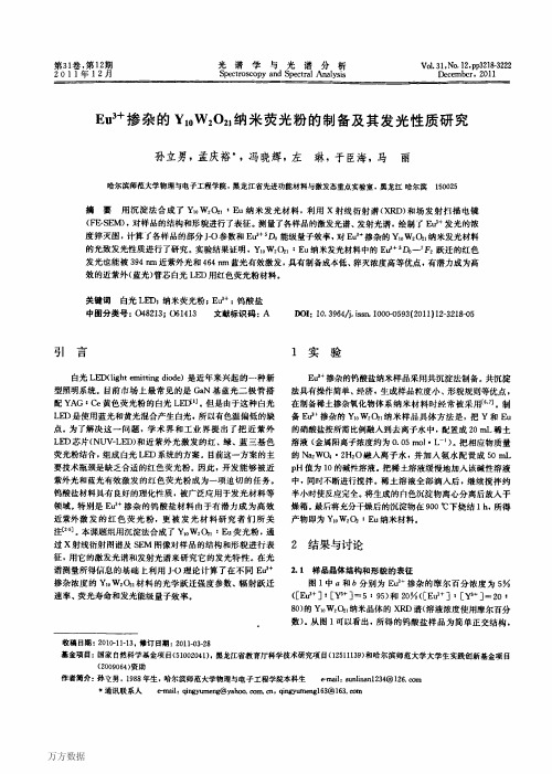
图 Z
Fg 2 i.
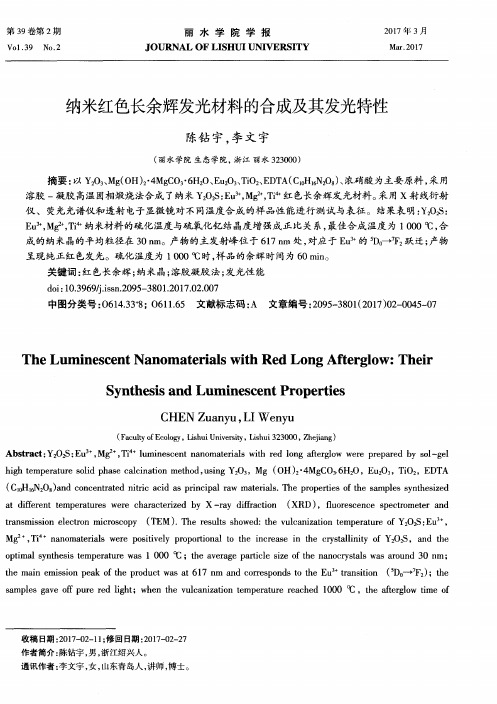
体立方 ZSM 的光致发光余辉 n : n
P o l iset cy bl cb c s l htu n cn d a o u ui r t om e e f k c y a
Z S: . M n.
}\ 二 洲
} 卜、为 、V
F 咬 m,]
;0 6
尸 讥
1 一」户 一J J + 、 味1 。L 」
“二 洲.+
 ̄ 、 . 、
三0 a .
‘护 卜
一 二,
1 . 卜 」 1 n 吕 肠
门. 幼 一 卜. 拟1
0 2
。 J
一 可
。一
} x . i =
叭
O
5 0 1 ( 1 1 0川
I 爪川
指数衰减, 余辉时间 分别为16 和1 1, 8p . 08.其幅度比 7. 为4 1前者是主 . 要的, 决定了1e /余辉时间,2纯立方 () 徽米体ZSM : 4s() ,: 9 p 3纯六角徽米体ZSM : 还有幅度很小的极长余辉成分) n 4 . n: 12 n . -( 。结果表明纳米 ZSM 荧光粉的光致发光余辉的确比对应的体材料( n: n 不管是六角还是立方) 都短, 但余辉仅缩短了几倍, 而
Ci ee hns)
[ 〕 hm r . i7 U i rt (r c . s a Cm ui tn Jl 1 7 4 C a a M Pr t n e i Fa e Pr nl m n ao , y o r as h v sy n ) eo o ci u 9 9
〔 〕LB n G o nx , n tg Il ne oi b tcC o M is ti p cs t c r tno 5 i , Cagi Wa Y en. u codp g re r n en r e o suta r sr i o h n i l u i n e f n y u n i rg s n u l f f a n o r a m tn S t u i s t s o [] AtPycSna 19, 3: - 7 h e . n ec ln e n po hr . a sa i , 1 4()40 9 ( Cis) ao oZ l r tn c h p J c h i ic 9 i f e o e 0 9 4 i ne n 【 ]Go nx , i . i sne ao s l n: p pr b ir n r m tis em m - 6 o Cagi L Bi Lmn c c onnc t oZSM r a d n g i a a rludr t h n i u ee f r a f n e y a c l n y e o w ea n o e m prue . r i - r, 5 6Sp.: - 8 ad ( h e ) ] O t nsLss 19. up)46 3, 43 Ci s . et [ ar J P c a o e 9 ( 3 4 n 2 i ne n
料余辉随粒径下降到纳米有五个数量级缩短的理 论模型。() 3实验工作中, Ba aa 对 hr v 纳米 ZS g .: Mn 的发光中心 M 的余辉在纳秒数量级没有 矛+ 重复 证 实。相 反, 人 如 巴黎 第 六 大 学 的 有 Ca ao hm r 测得的纳米 ZS Mn r n : 的余辉并不比对
机原料制备的纳米 Z S n : Mn可发明亮的橙色光, 且光致发光余辉为 2n, 0s比对应的体材料 Z S n: Mn 荧光粉的余辉 18 s . 短五个数量级。从体材 m 料到纳米材料, 发光亮度相当, 而发光余辉缩短五 个数量级的结果引起了全世界的广泛的重视。正 如盐谷繁雄在日 本全国荧光体同学会20 5 届学术
图3 体六角ZSM 的光致发光余辉 n n :
F . Po l iset a o bl h a nl t i 3 htu n c dc f k g a c s l g o m e n e y u e o r a x y
7 s: n. n M
da o ntcsl M ey a t ZS: n c f y r a n t y
应体材料的短[。() ] ’ 4市场上得到的体材料ZS n:
M 通常是六角和立方晶相的混相材料, n 例如在 80 0'锻烧成的体 ZS M 荧光粉, 0-90 - C n : n 大约为 7% 0 的六角晶相和 3%立方晶相[。由于体六 0 5 1 角ZSMn n : 荧光粉在光致激发下是极长余辉荧光 粉, 比体立方 ZS Mn n : 荧光粉余辉长, 所以。 将纳 米ZSMn立方) ZSMr n : ( 与体 n : 荧光粉比较余辉 . 时, 要说明所用的体 ZSMn n : 的晶相。() 5一个材 料的余辉不是常数, 它随着发光的激发方式、 激发 强度而变。如光致发光的长余辉材料在阴极射线 激发下可能成短余辉, 余辉缩短几个数量级。阴 极射线发光材料的余辉随着激发电子束流密度增 加而缩短。因此, 对不同材料对比余辉应采用相 同激发条件。上述分析表明, 仔细地将纳米 ZS n: M 荧光粉与对应的体材料进行余辉的对比测量 n 有 重要的实验和理论意义。本工作是用 N : d Y G四倍频脉冲激光余辉测量系统对立方纳米、 A 纯立方微米、 纯六角微米 ZS Mn n : 荧光粉进行余
收稿0 20- - : 期: 00 1 0 修订日 20- - 12 期:01 31 0 6 签金项目: 国家自 学基金( 5 06; 然科 1 7 4) 中国科 94 学院激发态物理开放实 和中国科 术大学结构分析开放实 验室 学技 验室资助项目 作者简介: 郭常新( 4 一 , 福建人. 1 2 ) 男, 9 中国科学技术大学物理系教授, 博士生导师, 现主耍从事 发光材料物理研究
会议纪念讲演[中指出的: ZSM 比对应 3 ] 纳米 n : n
体材料的余辉短了五个数量级, 而发光效率不降 低, 意味着它的发光巾心振子强度增强了五个数
量级。这个令人震惊的结果, 仅用 Ba a 的 hr v ga
“ 基质 5 一P状态的混合” 来解释是不够的, 必须
引入发光的特殊概念。此工作开辟 了 研究高效掺 杂型超微粒荧光粉的新方向, 意义重大。 在Ba a 的纳米 ZS M 发光S作发表 a hr v g n : n 后, 引发了世界范围内的纳米材料发光研究热潮。 但有五点情况值得注意:1由于纳秒余辉很难测 () 量, 很多作者在没测到这余辉前, 就引证Ba a hr v ga 的工作, 认为纳米材料的余辉会比体材料缩短五 个数量级, 将此看成是一个肯定的结果。() 2理论 工作中, h gv 的论文为依据, 以Ba aa r 提出荧光材
R v I 94 7 ()464 9 e . t e t,19 , 3 :1-1 2
〔 ] h ny S Hs r d u i s di I 3 Si oa io a f r n y g o . t n u e t n n y t u 二二 et ea [] Ci. mn it , 4 () 0 n m tis . n L i. t 19, :- ( a rl J h u .. 9 e 5 7 1 i n
不是五个数量级。
关 锐 词: 纳米荧光粉; n : 光致发光; ZSMn ; 余辉 中图分类号: 523 0 8.1 文献标识码: A 文章编号: 00 0220 ) - 2- 10- 3 ( 10 0 3 4 7 0 32 0
1 引
言
自 13 hr v首次公布了〔2 从 9 年Ba a 9 ga 1] ,用有
( 中国科学技术大学 物理系, 1 安徽 合肥
2 中国科学院激发态物理开放实验室,吉林 长春 102 30 1 3 中国科学伎术大学 结构分析开放实脸室, 安徽 合肥 202 306
摘要: 无机材 用 料在室温下通 胶法制 纳米ZS 荧光粉, 过溶 成了 nM n 立方晶 平均粒径为3m它的橙色 形, n
楚双指数衰减规律, 将图 l 的强度轴改用对数坐 a 标, 衰减曲线拟合出两条直线( l) () 图 b , 纯立 2 方微米体ZSM : s ) ) n : 94 ( 0 纯六角微米 n 4p 图2 ( 3 体ZSM : s还有幅度很小的极长余辉成 n: 12 ( n . m 分, 应属双曲线衰减规律)图3。在各图中, ( ) 实 线是实验曲线, 虚线为拟合曲线。对于 D CA R2 N :A dY G四倍频激光余辉测量系统, 为去除噪音 干扰, 图中的时间零点比激发光脉冲停止时间推 迟了该图时间轴全量程的 56 9。样品是否有短于 微秒的余辉还应该用其他实验来进一步测定。本 结果表明, ZS M 荧光粉的光致发光余辉 纳米 n : n 的在微秒量级以上有成分( 属于发光中心 M Z n十 的发光)的确比 , 对应的体材料( 不管是六角还是 立方) 都短, 但余辉仅缩短了几倍, 而不是五个数
[] J L mn , , 12 - 0 . 1 4 6&6 : 5 8 1. u i . 9 9 0 72
〔 ]Ba aa , l h D H n X ea. il ei 。 i nae - pd e y a o ZS . s 2 hr v R Glge , g t O tap pr s 工n gn e oe mnc sl f [] Py g N a r o , l pc r t a o e a sd r ts n J h
le ( ) l atmc ) ia a ad rh i ( , n r n o i g b
rs- el _ . d. y
万方数据
第 3期
郭常新, : 等 纳米 Z SMn荧光粉的余辉研究 . :
2 5 2
致谢 感谢中国科学院长春光学精密机械与物理
研究所激发态物理开放实验室吕少哲、 黄世华和
量级 。
I 0
辉时间为1 f和1 N 其幅度比为7 2( 8} 08 , 6 s 7s 8 图 2
l, a 前者是主要的, ) 决定了1e /余辉时间。 为看清