SPT9110中文资料
VITSON产品说明书中文英文

V I T S O N产品说明书中文英文TPMK standardization office【 TPMK5AB- TPMK08- TPMK2C- TPMK18】深圳市慧拓鑫科技有限公司Shenzhen Hui Tuo Xin Technology Co., Ltd.产品资料Product information1、TOP电源防雷箱系列(TOP Power lightning protection box series) (2)2、TP 限压型电源防雷模块系列(TP Voltage limiting type power supply lightning protection module series) (5)3、TP直流电源防雷模块系列(TP DC power supply lightning protection module series) (8)4、TCP电源未端精细防护防雷器系列(TCP Power supply terminal fine protective lightning arrester series) (11)5、TDC 电源插座(TDC Power supply lightning protection socket series) (14)6、TV 视频防雷器系列(TV Video arrester series) (17)7、T 视频/射频防雷器系列(T Video / RF lightning arrester series) (20)8、TC控制线路防雷器系列( TC Control circuit lightning arrester series) (23)9、10/100M网络线路防雷器(10/100M Network circuit lightning arrester) (25)10、通讯专线防雷器(Communication line lightning arrester) (28)11、TT天馈线路防雷器系列(TT Antenna line arrester series) (30)1、TOP电源防雷箱系列(TOP Power lightning protection box series)产品介绍Product introductionTOP电源防雷箱系列依据IEC标准设计,8/20波形最大通流容量20KA-100KA,能对电源系统的浪涌电压进行有效的钳制,电源B、C、D级产品均具备。
Eaton 9130 UPS 安全和一般信息指南说明书

00 1000Safety and General InformationSAVE THESE INSTRUCTIONSThis manual contains important instructions that should be followed during installation and maintenance of the UPS and batteries.Inspect the package contents upon receipt. Notify the carrier and dealer if there is any damages.• This UPS is intended for indoor use only.• Mains socket outlet that supplies the UPS shall be installed near the UPS and shall be easilyaccessible.• UPS must be connected to an earthed mains socket outlet.•batteries and required precautions.•When replacing battery the UPS must be OFF, and its AC inlet unplugged.• CAUTION Do not dispose of batteries in a re. The batteries may explode.•CAUTION Risk of explosion if battery is replaced by an incorrect type. Dispose of used batteries according to the instructions.•Do not open or mutilate batteries. They contain an electrolyte that is toxic and harmful to the skin and eyes.•CAUTION A battery can present a risk of electrical shock and high short circuit current.The following precautions should be observed when working on batteries.a. Remove watches, rings or other metal objects.e tools with insulated handles.c. Wear rubber gloves and boots.d.Do not lay tools or metal parts on top of batteries.e. Disconnect the charging source prior to connecting or disconnecting battery terminals.f.Determine if battery is inadvertently grounded. If inadvertently grounded, remove source fromground. Contact with any part of a grounded battery can result in electrical shock. The likelihood of such shock can be reduced if such grounds are removed during installation and maintenanceRadio Frequency WarningThis is a category C2 UPS product. In a residential environment, this product may cause radio interference, in which case the user may be required to take additional measures.FeaturesON/OFF button with indicator Battery connector Input power cordCircuit breakerEasy UPS BVS Series 500VA, 650VA, 800VA, 1000VA2Place and Power On1. Place the Easy UPS to avoid :• Direct sunlight • Excessive heat • Excessive moisture • Excessive dust/dirtFor operation, please place the unit on the floor.2. Connect the battery by pulling the battery handle up,and then pushing it into the unit.4. Plug the Easy UPS power cord directly into a wall outlet, not into a surge protector or power strip.5. Press the ON/OFF button to turn on the unit.The green “Power On” indicator confirms that the Easy UPS is on and ready to provide protection.The Easy UPS should charge for at least 6 hours to ensure sufficient runtime. The unit is being charged whenever it is connected to AC power, whether the unit is turned ON or OFF.*only for model with Schuko outletBattery backup and surge protected outletsAC power inlet with AC fuse*only for model with Schuko outlet36-8 Hours 9.25 cm x 16.05 cm x 30.5 cmSpecificationsInputOutputProtection Battery PhysicalV oltage Frequency230 V AC 50 Hz or 60 Hz Brownout Transfer Over-voltage Transfer170 V AC, typical 280 V AC, typicalUPS Capacity (total)500V A / 300W V oltage On Battery 230V AC 10%± Frequency - On Battery Transfer Time50 Hz / 60 Hz ± 1Hz6ms typicalTypical Recharge TimeNet WeightDimensions (Hx Wx D)12V , 7AH lead acidBVS500IBVS650IBVS800IBVS1000I650V A / 375W 800V A / 450W 1000V A / 600W12V , 4.5AH lead acid4.5 kg3.9 kg5.3 kg5.7 kg12V , 7AH lead acid12V , 9AH lead acidThe battery typically lasts for three to ve years.Environmental factors impact battery life.Elevated temperatures, high humidity, poor quality mains power, and frequent, short duration discharges will shorten battery life.The battery in the Easy UPS Series is not user-replaceable.Contact SEIT Technical Support for a list of authorized service centers near you.ModelWall Mount Installation• Horizontal installation, use 2 screws 11.1"(282 mm) apart.• Allow 5/16'’ (8 mm), of the screw to protrude from the wall.Easy UPS BVS Series 500VA, 650VA, 800VA, 1000VA AC InputCircuit Breaker Type(maintenance-free)Average Life5A 5A 7A 7A AC Input Fuse5A 5A 10A 10ALED ConditionOnOff Constant ToneOn (Off during 4 beeps) 4 beeps repeatedevery 30 secondsFlashingConstant beeping (every 1/2 second) Constant toneOffShort beep every 4 seconds Constant ToneAudible AlarmLong beep every 4 secondsS tatus IndicatorsOn-line - The Easy UPS is supplying AC power to the connected equipmentOn Line Overload - The power being used by the connected equipment has exceeded the capacity of the unit.Disconnect some equipment.Over-temperature - The unit is overheating and will operate in A VR mode for 5 minutes. The Easy UPS will shut down if the temperature is not lowered. Disconnect some of the connected equipment.On-Battery - The Easy UPS is supplying battery power.Low Battery - The Easy UPS is supplying battery power and the battery is near a total discharge state.Bad Battery Detected - The battery needs to be charged,or is at end of life.Low Battery Shutdown - During On Battery operation the battery power was almost completely exhausted, and the Easy UPS is waiting for AC power to return to normal.On Battery Overload - The connected equipment requires more power than provided by the Easy UPS battery.Unplug devices one at a time to remove overload. If the problem is not corrected, contact SEIT Technical SupportCharger Detected Fault - Easy UPS has an internal problem,and is no longer powering the load.Contact SEIT Technical SupportOver-temperature Protected - The Easy UPS hasoverheated and has shut down. Unplug connected devices one at a time or wait for a few hours for system to cool down.Constant b eeping (every 1/2 s econd)4Easy UPS BVS Series 500VA, 650VA, 800VA, 1000VAOperational FeaturesAutomatic V oltage Regulation boosts/trims the AC voltage when it drops/exceeds levels.This allows the equipment plugged into the unit to operate during low/high voltage conditions, conserving the battery power in the event of a power cut.The Easy UPS will switch to battery power if the input voltage level becomes too low/high for the Automatic V oltage Regulation to compensate, or if the AC power is distorted.Automatic Voltage Regulation (AVR)TroubleshootingProblem and Possible CauseThe Easy UPS will not turn onThe Easy UPS has not been turned on.SolutionPress the ON/OFF button.Make sure the power cord is securely connected to the wall outlet, and that there is AC power available at the wall outlet.Where applicable, check that the wall outlet is switched on.Remove all nonessential equipment connected to theoutlets. One at a time reconnect equipment to the Easy UPS.Charge the battery for 24 hours to make sure it is fully charged. If the overload condition still occurs, replace the battery.The Easy UPS is not connected to AC power,there is no AC power available at the wall outlet, or the AC power is experiencing a brownout or over voltage condition.The battery is disconnected.Connected equipment loses powerA Easy UPS overload condition has occurred.The Easy UPS battery is completely discharged.The Easy UPS may require service.The Easy UPS is operating on battery power.The Easy UPS battery has approximately empty and will shutdownThe ON/OFF button is green and ashing every 30 seconds. 4 beeps repeated every 30 seconds.The ON/OFF button ashes green and constant beeps every 1/2 second.Connected equipment does not accept the step-approximated sine waveform from the Easy UPS.Refer to the Place and Power On on page 2.Connect the Easy UPS to AC power and allow the battery to recharge for ten hours.Contact Schneider Electric Technical Support for more in depth troubleshootingThe Easy UPS is operating normally on batterypower. At this point the user should save all open les,and shutdown the computer. When AC power is restored the battery will recharge.The Easy UPS battery is near a total discharge state.At this point the user should save all open les, and shutdown the computer. When AC power is restored the battery will recharge.The output waveform is intended for computers and peripheral devices. It is not intended for use with motor driven equipment.The Easy UPS has an inadequate battery runtime The battery is not fully charged.The battery is near the end of useful life and should be replaced.Leave the Easy UPS connected to AC power for ten hours while the battery charges to full capacity.As a battery ages, the runtime capability decreases.Contact Schneider Electric at the website , to order replacement batteries.The UPS have shut down due to low battery,but control power exists.The UPS and outlets are off but the UPS keeps beeping once every 4 seconds. The alarm will mute after 32 seconds.The UPS will return to normal operation once the AC input voltage has returned to a normal range.5Easy UPS BVS Series 500VA, 650VA, 800VA, 1000VAServiceIf the unit requires service, do not return it to the dealer. Follow these steps:1. Review the Troubleshooting section of the manual to eliminate common problems.2. If the problem persists, contact Schneider Electric IT (SEIT) Customer Support through the Schneider Electric website, .a. Note the model number and serial number and the date of purchase. The model and serial numbers are located on the rear panel of the unit.b.Call SEIT Customer Support and a technician will attempt to solve the problem over the phone. If this is not possible, the technician will issue a Returned Material Authorization Number (RMA#).c. If the unit is under warranty, the repairs are free.d.Service procedures and returns may vary internationally. Refer to the Schneider Electric website for country specific instructions.3. Pack the unit in the original packaging whenever possible to avoid damage in transit. Never use foam beads for packaging. Damage sustained in transit is not covered under warranty.4. Always DISCONNECT THE UPS BATTERIES before shipping. The United States Department of Transportation (DOT), and the International Air Transport Association (IATA) regulations require that UPS batteries be disconnected before shipping. The internal batteries may remain in the UPS.5. Write the RMA# provided by Customer Support on the outside of the package.6. Return the unit by insured, pre-paid carrier to the address provided by Customer SupportSchneider Electric IT Customer Support WorldwideWarrantyRegister y our p roduct o n-line. h ttp://The standard warranty is two (2) years from the date of purchase. SEIT standard procedure is to replace the original unit with a factory reconditioned unit. Customers who must have the original unit back due to the assignment of asset tags and set depreciation schedules must declare such a need at first contact with an SEIT Technical Support representative. SEIT will ship the replacement unit once the defective unit has been received by the repair department, or cross-ship upon the receipt of a valid credit card number. The customer pays for shipping the unit to SEIT. SEIT pays ground freight transportation costs to ship the replacement unit to the customer.For country specific customer support, go to the Schneider Electric website, www .apc .com .EN 990-592301/2018© 2018 Schneider Electric. The Schneider Electric logo is owned by Schneider Electric Industries S.A.S., or their af liated companies. All other trademarks are property of their respective owners.。
TRSL-9110FAW中文资料
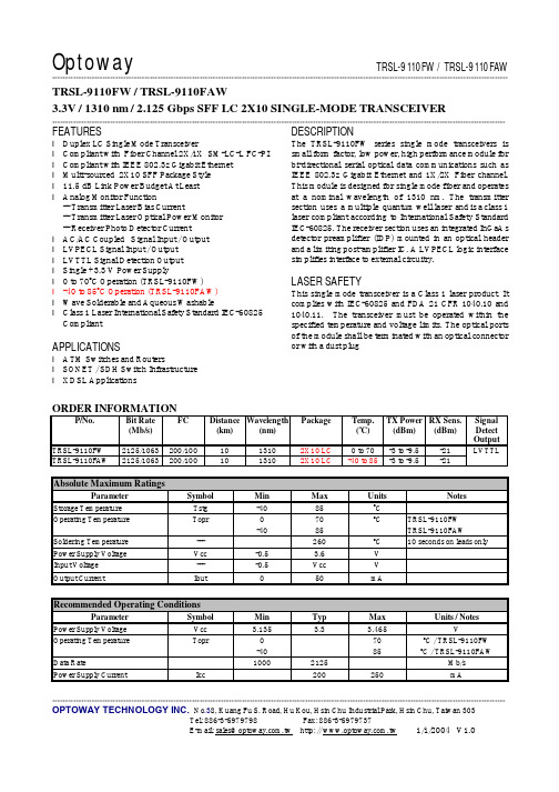
Optoway TRSL-9110FW / TRSL-9110FAW*********************************************************************************************************************************************************************************************************************************************************************************************************************************************************OPTOWAY TECHNOLOGY INC. No .38, Kuang Fu S. Road, Hu Kou, Hsin Chu Industrial Park, Hsin Chu, Taiwan 303Tel: 886-3-5979798 Fax: 886-3-5979737E-mail: sales@ http: // 1/1/2004 V1.0TRSL-9110FW / TRSL-9110FAW3.3V / 1310 nm / 2.125 Gbps SFF LC 2X10 SINGLE-MODE TRANSCEIVER****************************************************************************************************************************************************************************FEATURESl Duplex LC Single Mode Transceiver l Compliant with Fiber Channel 2X/1X SM-LC-L FC-PI l Compliant with IEEE 802.3z Gigabit Ethernet l Multi-sourced 2X10 SFF Package Style l 11.5 dB Link Power Budget At Least l Analog Monitor Function-- Transmitter Laser Bias Current-- Transmitter Laser Optical Power Monitor -- Receiver Photo Detector Current l AC/AC Coupled Signal Input / Output l LVPECL Signal Input / Output l LVTTL Signal Detection Output l Single +3.3 V Power Supply l 0 to 70o C Operation (TRSL-9110FW) l -40 to 85o C Operation (TRSL-9110FAW) l Wave Solderable and Aqueous Washable l Class 1 Laser International Safety Standard IEC-60825 CompliantAPPLICATIONSl ATM Switches and Routers l SONET / SDH Switch Infrastructure l XDSL ApplicationsDESCRIPTIONThe TRSL-9110FW series single mode transceivers issmall form factor, low power, high performance module for bi-directional serial optical data communications such as IEEE 802.3z Gigabit Ethernet and 1X/2X Fiber channel. This module is designed for single mode fiber and operates at a nominal wavelength of 1310 nm. The transmitter section uses a multiple quantum well laser and is a class 1 laser compliant according to International Safety Standard IEC-60825. The receiver section uses an integrated InGaAs detector preamplifier (IDP) mounted in an optical header and a limiting post-amplifier IC. A LVPECL logic interface simplifies interface to external circuitry.LASER SAFETYThis single mode transceiver is a Class 1 laser product. It complies with IEC-60825 and FDA 21 CFR 1040.10 and 1040.11. The transceiver must be operated within the specified temperature and voltage limits. The optical ports of the module shall be terminated with an optical connector or with a dust plugORDER INFORMATIONP/No. Bit Rate (Mb/s)FCDistance (km) Wavelength (nm) Package Temp. (o C) TX Power (dBm) RX Sens. (dBm) Signal Detect Output TRSL-9110FW 2125/1063 200/100 10 1310 2X10 LC 0 to 70 -3 to -9.5 -21 TRSL-9110F AW 2125/1063 200/1001013102X10 LC-40 to 85-3 to -9.5-21LVTTLAbsolute Maximum RatingsParameterSymbol Min Max Units NotesStorage Temperature Tstg -40 85 o COperating Temperature Topr 0 -40 70 85 o CTRSL-9110FW TRSL-9110FAWSoldering Temperature --- 260 oC 10 seconds on leads only Power Supply Voltage Vcc -0.5 3.6 V Input Voltage --- -0.5 Vcc VOutput CurrentIout50mARecommended Operating ConditionsParameterSymbol Min Typ Max Units / NotesPower Supply Voltage Vcc 3.135 3.3 3.465 VOperating Temperature Topr 0 -40 70 85 oC / TRSL-9110FW oC / TRSL-9110FAWData Rate1000 2125 Mb/s Power Supply CurrentIcc200250mA**************************************************************************************************************************************************************************** Transmitter Specifications (0o C < Topr < 70o C, 3.135V < Vcc < 3. 465V)Parameter Symbol Min Typ Max Units NotesOpticalOptical Transmit Power Po -9.5 --- -3 dBm 1Output Center Wavelength λ1270 1310 1360 nmOutput Spectrum Width ∆λ--- --- 2.5 nm RMS (σ)Extinction Ratio E R9 --- dBOptical Rise Time t r160 ps 20% to 80% Values Optical Fall Time t f160 ps 20% to 80% Values Relative Intensity Noise RIN -120 dB/HzElectricalData Input Current – Low I IL-350 µAData Input Current – High I IH350 µADifferential Input Voltage V IH - V IL300 1600 mVData Input Voltage – Low V IL - V CC-2.0 -1.58 V 2Data Input Voltage -- High V IH - V CC-1.1 -0.74 V 2TX Disable Input Voltage – Low T DIS0 0.5 VTX Disable Input Voltage – High T DIS 2.0 Vcc VTX Disable Assert Time T ASSERT10 µsTX Disable Deassert Time T DEASSERT50 µsNotes: 1. Output power is power coupled into a 9/125 µm single mode fiber.2. These inputs are compatible with 10K, 10KH and 100K ECL and PECL inputs.Receiver Specifications(0o C < Topr < 70o C, 3.135V < Vcc < 3.465V)Parameter Symbol Min Typ Max Units NotesOpticalSensitivity @ 2.125 Gbps Sen1 --- -21 dBm 1 Sensitivity @ 1.25 Gbps Sen2 -22 dBm 1Maximum Input Power Pin -3 --- dBmSignal Detect -- Asserted Pa --- --- -21 dBm Transition: low to high Signal Detect -- Deasserted Pd -35 --- --- dBm Transition: high to low Signal Detect -- Hysteresis 1.0 --- 4.0 dBWavelength of Operation 1100 --- 1600 nmElectricalData Output Voltage – Low V OL - V CC-2.0 -1.58 V 2Data Output Voltage – High V OH - V CC-1.1 -0.74 V 2Signal Detect Output Voltage -- Low V SDL0 0.5 VSignal Detect Output Voltage -- High V SDH 2.0 Vcc+0.3 VNotes: 1. Minimum sensitivity and saturation levels at BER=1E-12 for a 27-1 PRBS.2. These outputs are compatible with 10K, 10KH and 100K ECL and PECL inputs.**************************************************************************************************************************************************************************** OPTOWAY TECHNOLOGY INC. No.38, Kuang Fu S. Road, Hu Kou, Hsin Chu Industrial Park, Hsin Chu, Taiwan 303 Tel: 886-3-5979798 Fax: 886-3-5979737**************************************************************************************************************************************************************************** ANALOG DIAGNOSTICS FUNCTIONSParameter Symbol Min Typ Max Units Notes TransmitterLaser Bias Current Monitor Bmon+, Bmon- 0 Vcc V 1Monitor Photodiode Current Monitor Pmon+,Pmon- 0 Vcc V 2ReceiverReceived Photocurrent Rpd 0 1 mA 3 Photodiode Responsivity R 0.5 0.9 1.0 A/WApplied Voltage at VpdR pin Vpd 2.4 Vcc V 3Notes: 1. PIN 17 and 18 provide an analog voltage output proportional to the laser bias current, based on the following formula: Ibias = V (Bmon+ - Bmon-) / 10 Ω. See below the equivalent circuit.2. PIN 19 and 20 provide an analog voltage output proportional to the monitor photodiode current, based on thefollowing formula: Imon = V (Pmon+ - Pon-) / 200Ω. See below the equivalent circuit.3. PIN 1 is used to monitor the received photocurrent. It must be connected to a positive voltage within the specifiedabove. The received power is given by the photocurrent multiplied by the photodiode responsivity.**************************************************************************************************************************************************************************** OPTOWAY TECHNOLOGY INC. No.38, Kuang Fu S. Road, Hu Kou, Hsin Chu Industrial Park, Hsin Chu, Taiwan 303 Tel: 886-3-5979798 Fax: 886-3-59797372. Veer and Veet are not internally connected to each other.3. 50 Ω line pattern and component placements on TD+/TD- and RD+/RD- lines shall be symmetrical for better impedancematching.**************************************************************************************************************************************************************************** OPTOWAY TECHNOLOGY INC. No.38, Kuang Fu S. Road, Hu Kou, Hsin Chu Industrial Park, Hsin Chu, Taiwan 303 Tel: 886-3-5979798 Fax: 886-3-59797371) Standard CaseTRSL-9110FW / TRSL-9110FAW2) Extended CaseTRSL-9110FWE / TRSL-9110FAWENote: Specifications subject to change without notice.**************************************************************************************************************************************************************************** OPTOWAY TECHNOLOGY INC. No.38, Kuang Fu S. Road, Hu Kou, Hsin Chu Industrial Park, Hsin Chu, Taiwan 303 Tel: 886-3-5979798 Fax: 886-3-5979737E-mail: sales@ http: // 1/1/2004 V1.0。
INTERSIL EL9110 说明书
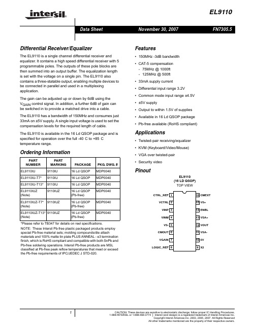
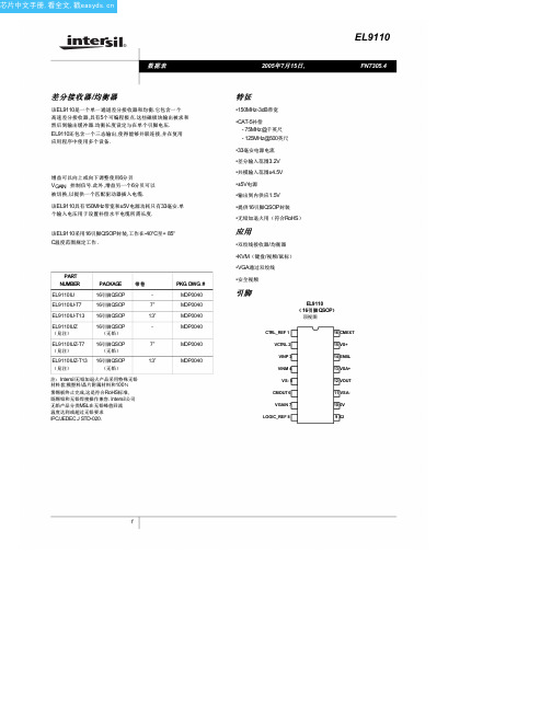
®EL9110Differential Receiver/EqualizerThe EL9110 is a single channel differential receiver and equalizer. It contains a high speed differential receiver with 5 programmable poles. The outputs of these pole blocks are then summed into an output buffer. The equalization length is set with the voltage on a single pin. The EL9110 also contains a three-statable output, enabling multiple devices to be connected in parallel and used in a multiplexing application.The gain can be adjusted up or down by 6dB using theV GAIN control signal. In addition, a further 6dB of gain can be switched in to provide a matched drive into a cable.The EL9110 has a bandwidth of 150MHz and consumes just 33mA on ±5V supply. A single input voltage is used to set the compensation levels for the required length of cable.The EL9110 is available in the 16 Ld QSOP package and is specified for operation over the full -40°C to +85°C temperature range.Features•150MHz -3dB bandwidth•CAT-5 compensation-75MHz @ 1000ft-125MHz @ 500ft•33mA supply current •Differential input range 3.2V •Common mode input range ±4.5V •±5V supply•Output to within 1.5V of supplies •Available in 16 Ld QSOP package •Pb-free available (RoHS compliant) Applications•Twisted-pair receiving/equalizer •KVM (Keyboard/Video/Mouse)•VGA over twisted-pair•Security videoPinoutEL9110(16 LD QSOP)TOP VIEWOrdering InformationPART NUMBERPARTMARKING PACKAGE PKG. DWG. #EL9110IU9110IU16 Ld QSOP MDP0040 EL9110IU-T7*9110IU16 Ld QSOP MDP0040 EL9110IU-T13*9110IU16 Ld QSOP MDP0040EL9110IUZ (Note)9110IUZ16 Ld QSOP(Pb-free)MDP0040EL9110IUZ-T7* (Note)9110IUZ16 Ld QSOP(Pb-free)MDP0040EL9110IUZ-T13* (Note)9110IUZ16 Ld QSOP(Pb-free)MDP0040*Please refer to TB347 for details on reel specifications.NOTE:These Intersil Pb-free plastic packaged products employ special Pb-free material sets; molding compounds/die attach materials and 100% matte tin plate PLUS ANNEAL - e3 termination finish, which is RoHS compliant and compatible with both SnPb and Pb-free soldering operations. Intersil Pb-free products are MSL classified at Pb-free peak reflow temperatures that meet or exceed the Pb-free requirements of IPC/JEDEC J STD-020.12341615141356712111089CTRL_REFVCTRLVINPVINMVS-CMOUTVGAINLOGIC_REFCMEXTVS+ENBLVSA+VOUTVSA-0VX2IMPORTANT NOTE:All parameters having Min/Max specifications are guaranteed. Typ values are for information purposes only. Unless otherwise noted, all tests are at the specified temperature and are pulsed tests, therefore: T J = T C = T AAbsolute Maximum Ratings (T A = +25°C)Thermal InformationSupply Voltage between V S + and V S -. . . . . . . . . . . . . . . . . . . . .12V Maximum Continuous Output Current. . . . . . . . . . . . . . . . . . . 30mA Pin Voltages. . . . . . . . . . . . . . . . . . . . . . . . . V S - -0.5V to V S + +0.5VPower Dissipation . . . . . . . . . . . . . . . . . . . . . . . . . . . . . See Curves Storage Temperature. . . . . . . . . . . . . . . . . . . . . . . .-65°C to +150°C Ambient Operating Temperature . . . . . . . . . . . . . . . .-40°C to +85°C Die Junction Temperature . . . . . . . . . . . . . . . . . . . . . . . . . . .+150°C Pb-free reflow profile . . . . . . . . . . . . . . . . . . . . . . . . . .see link below /pbfree/Pb-FreeReflow.aspCAUTION: Do not operate at or near the maximum ratings listed for extended periods of time. Exposure to such conditions may adversely impact product reliability and result in failures not covered by warranty.Electrical SpecificationsV SA + = V A + = +5V, V SA - = V A - = -5V, T A = +25°C, Unless Otherwise SpecifiedPARAMETER DESCRIPTIONCONDITIONSMIN (Note 1)TYPMAX (Note 1)UNITAC PERFORMANCE BW Bandwidth (See Figure 1)150MHz SR Slew RateV IN = -1V to +1V, V G = 0.35, V C = 0, R L = 75 + 75Ω 1.5V/ns THDTotal Harmonic Distortion10MHz 1V P-P out, V G = 0.35V, X2 gain, V C = 0-50dBcDC PERFORMANCE V OSOffset Voltage (bin #1)X2 gain, no equalization-250-10+250mV Offset Voltage (bin #2)CPI9049mVINPUT CHARACTERISTICS CMIR Common-mode Input Range Common-mode extension off -4/+3.5V CMIRx Extended CMIR Common-mode extension on±4.5V O NOISE Output NoiseV G = 0.35, X2 gain, 75 + 75Ω load, V C = 0.625mV RMS CMRR Common-mode Rejection Ratio Measured at 10kHz 60dB CMRR+Common-mode Rejection Ratio Measured at 10MHz 50dB CMBW CM Amplifier Bandwidth 10K || 10pF load 50MHz CM SLEW CM Slew RateMeasured @ +1V to -1V 100V/µs C INDIFF Differential Input Capacitance Capacitance V INP to V INM 600fF R INDIFF Differential Input Resistance Resistance V INP to V INM12.4M ΩC INCM CM Input Capacitance Capacitance V INP = V INM to ground 1.2pF R INCM CM Input Resistance Resistance V INP = V INM to ground 1 2.8M Ω+I IN Positive Input Current DC bias @ V INP = V INM = 0V 1µA -I IN Negative Input Current DC bias @ V INP = V INM = 0V1µA V INDIFFDifferential Input RangeV INP - V INM when slope gain falls to 0.92.53.2VOUTPUT CHARACTERISTICS V O Output Voltage Swing R L = 150Ω±3.5V I OUT Output Drive Current R L = 10Ω, V INP = 1V, V INM = 0V, X2 = gain, V G = 0.355060mA R OUTCM CM Output Resistance at 100kHz30ΩDiffGain Differential GainV C = 0, V G = 0.35, X2 = 5, R L = 75 + 75Ω0.85 1.01.1SUPPLY I SON Supply Current V ENBL = 5, V INM = 02738mA I SOFFSupply CurrentV ENBL = 0, V INM = 00.40.8mAPSRRPower Supply Rejection RatioDC to 100kHz, ±5V supply60dBLOGIC CONTROL PINS V HI Logic High Level V IN - V LOGIC ref for guaranteed high level 1.35V V LOW Logic Low Level V IN - V LOGIC ref for guaranteed low level 0.8V I LOGICH Logic High Input Current V IN = 5V, V LOGIC = 0V 50µA I LOGICL Logic Low Input CurrentV IN = 0V, V LOGIC = 0V15µANOTE:1.Parts are 100% tested at +25°C. Over-temperature limits established by characterization and are not production tested.Electrical SpecificationsV SA + = V A + = +5V, V SA - = V A - = -5V, T A = +25°C, Unless Otherwise Specified (Continued)PARAMETER DESCRIPTIONCONDITIONSMIN (Note 1)TYP MAX (Note 1)UNIT Pin DescriptionsPIN NUMBERPIN NAME PIN TYPE PIN FUNCTION1CTRL_REF Input Reference voltage for V GAIN and V CTRL pins 2VCTRL Input Control voltage (0 to 1V) to set equalization 3VINP Input Positive differential input 4VINM Input Negative differential input 5VS-Power -5V to core of chip6CMOUT Output Output of common mode voltage present at inputs 7VGAIN Input Control voltage to set overall gain (0V to 1V)8LOGIC_REFInput Reference voltage for all logic signals 9X2Logic InputLogic signal; low - gain = 1, high - gain = 2100V 0V reference for output voltage 11VSA-Power -5V to output buffer12VOUT Output Single-ended output voltage reference to pin 1013VSA+Power +5V to output buffer14ENBL Logic Input Logic signal to enable pin; low - disabled, high - enabled 15VS+Power +5V to core of chip16CMEXTLogic Input Logic signal to enable CM range extension; active highTypical Performance CurvesFIGURE 1.FREQUENCY RESPONSE FIGURE 2.TOTAL HARMONIC DISTORTIONFIGURE 3.RISE TIME FIGURE MON MODE REJECTIONFIGURE 5.CM AMPLIFIER BANDWIDTH FIGURE 6.PSRR vs FREQUENCY531-1-3-51M10M100M FREQUENCY (Hz)G A I N (d B )V GAIN = 0V V CTRL = 0V R LOAD = 150ΩX2 = OFF-40-45-50-55-60-650.1M1M 10M 100MFREQUENCY (Hz)T H D (d B c )V GAIN = 0V V CTRL = 0V V SS = +5V V EE = -5VR LOAD = 150ΩX2 = OFFINPUT = 0dBm2ns/DIV200mV/DIVV CTR = 0V V GAIN = 0.35V X2 = ON-20-40-60-80-100100k1M 10M 100MFREQUENCY (Hz)C M R R (d B c )420-2-4-6100k1M 10M 100MFREQUENCY (Hz)G A I N (d B )V GAIN = 0.35V V CTRL = 0V R LOAD = 150ΩX2 = ON-20-40-60-80-100-1201010k 10M 100MFREQUENCY (Hz)-P S R R (d B )100100k 1k 1M V EE = -5V V CTRL = 0V V GAIN = 0VINPUTS ON GNDFIGURE 7.PSRR vs FREQUENCYFIGURE 8.GAIN AS THE FUNCTION OF V CTRLFIGURE 9.GROUP DELAY AS THE FUNCTION OF THEFREQUENCY REPONSE CONTROL VOLTAGE (V CTRL )FIGURE 10.PACKAGE POWER DISSIPATION vs AMBIENTTEMPERATUREFIGURE 11.PACKAGE POWER DISSIPATION vs AMBIENT TEMPERATURETypical Performance Curves (Continued)0-20-40-60-80-1001010k10M100MFREQUENCY (Hz)+P S R R (d B )100100k1k1MV CC = 5V V CTRL = 0V V GAIN = 0VINPUTS ON GND10dB/DIV1MFREQUENCY (Hz)10M 100MG A I N (d B )100mV STEPV CTRL = 0mVV CTR = 800mV-20-100102030405060100mV STEPV CTRL = 0mVV CTRL = 900mV1M100M FREQUENCY (Hz)10M200M503010-10-30-50G R O U P D E L A Y (n s )10ns/DIV791mWθJA =158°C /WQ S O P 161.41.210.80.60.200255075100150AMBIENT TEMPERATURE (°C)P O W E R D I S S I P A T I O N (W )12585JEDEC JESD51-3 LOW EFFECTIVE THERMAL CONDUCTIVITY TEST BOARD0.41.116W θJA =112°C /WQ SO P 161.81.610.80.60.200255075100150AMBIENT TEMPERATURE (°C)P O W E R D I S S I P A T I O N (W )12585JEDEC JESD51-7 HIGH EFFECTIVE THERMAL CONDUCTIVITY TEST BOARD0.41.41.2Applications InformationLogic ControlThe EL9110 has three logical input pins, Chip Enable (ENBL), Common Mode Extend (CMEXT), and Switch Gain (X2). The logic circuits all have a nominal threshold of 1.1V above the potential of the logic reference pin. In most applications it is expected that this chip will run from a +5V, 0V, -5V supply system with logic being run between 0V and +5V. In this case the logic reference voltage should be tied to the 0V supply. If the logic is referenced to the -5V rail, then the logic reference should be connected to -5V. The logic reference pin sources about 60µA and this will rise to about 200µA if all inputs are true (positive).The logic inputs all source up to 10µA when they are held at the logic reference level. When taken positive, the inputs sink a current dependent on the high level, up to 50µA for a high level 5V above the reference level.The logic inputs, if not used, should be tied to the appropriate voltage in order to define their state.Control Reference and Signal ReferenceAnalog control voltages are required to set the equalizer and contrast levels. These signals are voltages in the range 0V to 1V, which are referenced to the control reference pin. It is expected that the control reference pin will be tied to 0V and the control voltage will vary from 0V to 1V. It is; however, acceptable to connect the control reference to any potential between -5V and 0V to which the control voltages are referenced.The control voltage pins themselves are high impedance. The control reference pin will source between 0µA and200µA depending on the control voltages being applied.The control reference and logic reference effectively remove the necessity for the 0V rail and operation from ±5V (or 0V and 10V) only is possible. However we still need a further reference to define the 0V level of the single ended output signal. The reference for the output signal is provided by the 0V pin. The output stage cannot pull fully up or down to either supply so it is important that the reference is positioned to allow full output swing. The 0V reference should be tied to a 'quiet ground' as any noise on this pin is transferred directly to the output. The 0V pin is a high impedance pin and draws dc bias currents of a few µA and similar levels of AC current.Common Mode ExtensionThe common mode extension circuitry extends the range of input common mode voltage before the input differential amplifier is overloaded. It does this by reducing the voltage equally at both inputs of the first differential amplifier as the common mode signal rises towards the supply. Similarly, when the common mode input signal goes low, the inputs to the first differential amplifier are raised whilst preserving the differential signal and maintain the amplifier within its common mode operating range.This operation may not always be desirable. A problem occurs because the EL9110 sinks or sources a common mode current though its input pins to create the common mode offset voltage. Assuming the system has been set up so that the differential line has a well-balanced impedance, then a problem will only occur when the common mode impedance to ground is not low. This will occur in systems where the inputs to the EL9110 are AC coupled. In such systems it is recommended that the common mode extension be disabled. In systems where the differential input signal is directly coupled and has its common mode level defined by a low impedance line driver, the common mode extension circuitry can extend the total common mode range by 2V to 3V.EqualizingWhen transmitting a signal across a twisted pair cable, it is found that the high frequency (above 1MHz) information is attenuated more significantly than the information at low frequencies. The attenuation is predominantly due to resistive skin effect losses and has a loss curve which depends on the resistivity of the conductor, surface condition of the wire and the wire diameter. For the range of high performance twisted pair cables based on 24awg copper wire (Cat 5 etc.) these parameters vary only a little between cable types, and in general cables exhibit the same frequency dependence of loss. (The lower loss cables can be compared with somewhat longer lengths of their more lossy brothers.) This enables a single equalizing law equation to be built into the EL9110.With a control voltage applied between pins 2 and 1, the frequency dependence of the equalization is shown in Figure8. The equalization matches the cable loss up to about 100MHz. Above this, system gain is rolled off rapidly to reduce noise bandwidth. The roll-off occurs more rapidly for higher control voltages, thus the system (cable + equalizer) bandwidth reduces as the cable length increases. This is desirable, as noise becomes an increasing issue as the equalization increases.The cable loss for 100m, 200m, and 300m of CAT 5 cable, based on manufacturer's loss curves is shown in Figure 14.Thus:•100m requires V C = 0.2V•200m requires V C = 0.6Vand:•300m requires V C = 1.0V approximatelyContrastBy varying the voltage between pins 7 and 1, the gain of the signal path can be changed in the ratio 4:1. The gain change varies almost linearly with control voltage. For normaloperation it is anticipated the X2 mode will be selected and the output load will be back matched. A unity gain to the output load will then be achieved with a gain control voltage of about 0.35V. This allows the gain to be trimmed up or down by 6dB to compensate for any gain/loss errors that affect the contrast of the video signal. Figure 12 shows an example plot of the gain to the load with gain control voltage.Circuit and Layout RecommendationThe interconnection cable is a transmission line therefore for proper function it should be treated like transmission line, a refection-free termination is necessary.A reflection-free termination is a real "ohmic" resistor with as less as possible reactive parasitic.The traces of the layout, up to the point where of thetermination resistor placed, are part of the transmission line which also includes the cable's connector. A connector with a better controlled impedance is an obligation for good picture quality. The termination resistor should be placed close to the inputs of the device's pins (pin 3 and pin 4.) The small capacitance differential and common modecapacitance of the input pins of the device makes it possible to connect parallel to the termination resistor.The cable will work as an antenna for all the RF spectrum which is "in the air" where the cable is used. The spectrum, particularly its common mode components, could and will contain high energy level of transients which are above the built-in protection level of the device and easily could damage its inputs. Using a transient protection circuit according to the given application is recommended. Since the used signal's bandwidth is in the range of 100MHz, for layout and power supply bypassing the roles of RF design should be applied.The following picture is taken from the DB9110 demo-board's layout. For better visibility the ground plain is removed.The ground plane is shown in Figure 14.0.8V GAIN0.41.02.01.81.41.00.60.4G A I N (V )0.60.21.61.20.8FIGURE 12.VARIATION OF GAIN WITH GAIN CONTROLVOLTAGE102030405060700.01M0.10M 1M10M 100MFREQUENCY (Hz)A T T E N U A T I O N (dB )FIGURE 13.CAT-5 CABLE ATTENUATION CHARACTERISTICS300M200M100M 50MThe accompanying circuit diagram is shown in Figure 15.Block Diagram12341615141356712111089CTRL_REFVCTRLVINPVINMVS-CMOUTVGAINLOGIC_REFCMEXTVS+ENBLVSA+VOUTVSA-0VX2R11330ΩC51µFR6R7R9R5C101µFR12330ΩC91µFC81nFC111nFC71µFC61nFTP7FIGURE 15.CIRCUIT DIAGRAMV S- & V SA- connected to -5VV S+ & V SA+ connected to +5VGAINASPCONTROLASP+BIASCIRCUITRYTypical ApplicationV CTRL0.1µF100-5V0.1µFCM OUT+5V0.1µF+5V-5V750.1µF+5V 12341615141356712111089CTRL_REFVCTRLVINPVINMVS-CMOUTVGAINLOGIC_REFCMEXTVS+ENBLVSA+VOUTVSA-0VX2All Intersil U.S. products are manufactured, assembled and tested utilizing ISO9000 quality systems.Intersil Corporation’s quality certifications can be viewed at /design/qualityIntersil products are sold by description only. Intersil Corporation reserves the right to make changes in circuit design, software and/or specifications at any time without notice. Accordingly, the reader is cautioned to verify that data sheets are current before placing orders. Information furnished by Intersil is believed to be accurate and reliable. However, no responsibility is assumed by Intersil or its subsidiaries for its use; nor for any infringements of patents or other rights of third parties which may result from its use. No license is granted by implication or otherwise under any patent or patent rights of Intersil or its subsidiaries.For information regarding Intersil Corporation and its products, see Quarter Size Outline Plastic Packages Family (QSOP)0.010C A BSEATING PLANE DETAIL XE E11(N/2)(N/2)+1NPIN #1I.D. MARKb0.004C cASEE DETAIL "X"A24°±4°GAUGE PLANE 0.010LA1DB HCeA0.007C A BL1MDP0040QUARTER SIZE OUTLINE PLASTIC PACKAGES FAMILYSYMBOL INCHESTOLERANCE NOTESQSOP16QSOP24QSOP28A 0.0680.0680.068Max.-A10.0060.0060.006±0.002-A20.0560.0560.056±0.004-b0.0100.0100.010±0.002-c 0.0080.0080.008±0.001-D 0.1930.3410.390±0.0041, 3E0.2360.2360.236±0.008-E10.1540.1540.154±0.0042, 3e 0.0250.0250.025Basic -L 0.0250.0250.025±0.009-L10.0410.0410.041Basic -N162428Reference-Rev. F 2/07NOTES:1.Plastic or metal protrusions of 0.006” maximum per side are not included.2.Plastic interlead protrusions of 0.010” maximum per side are not included.3.Dimensions “D” and “E1” are measured at Datum Plane “H”.4.Dimensioning and tolerancing per ASME Y14.5M-1994.。
SPS-9110AFWG中文资料
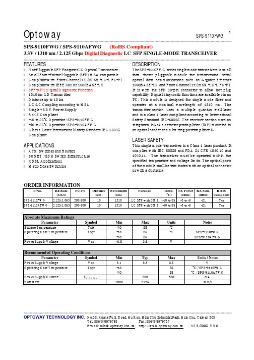
Optoway SPS-9110FWG**********************************************************************************************************************************************************************************************************************************************************************************************************************************************OPTOWAY TECHNOLOGY INC. No .38, Kuang Fu S. Road, Hu Kou, Hsin Chu Industrial Park, Hsin Chu, Taiwan 303Tel: 886-3-5979798 Fax: 886-3-5979737E-mail: sales@ http: // 12/1/2005 V2.01SPS-9110FWG / SPS-9110AFWG (RoHS Compliant)3.3V / 1310 nm / 2.125 Gbps Digital Diagnostic LC SFP SINGLE-MODE TRANSCEIVER **********************************************************************************************************************************************************************FEATURESl Hot-Pluggable SFP Footprint LC Optical Transceiver l Small Form-Factor Pluggable (SFP) MSA compatible l Compliant with Fibre Channel 1X/2X SM-LC-L FC-PI l Compliant with IEEE 802.3z 1000BASE-LX l SFF-8472 Digital Diagnostic Function l 1310 nm LD Transmitter l Distance up to 10 kml AC/AC Coupling according to MSA l Single +3.3 V Power Supply l RoHS Compliantl -10 to 85o C Operation: SPS-9110FWG l -40 to 85o C Operation: SPS-9110AFWGl Class 1 Laser International Safety Standard IEC 60825 CompliantAPPLICATIONSl ATM Switches and Routersl SONET / SDH Switch Infrastructure l XDSL Applications l Metro Edge SwitchingDESCRIPTIONThe SPS-9110FWG series single mode transceivers is small form factor pluggable module for bi-directional serial optical data communications such as Gigabit Ethernet 1000BASE-LX and Fibre Channel 1x/2x SM-LC-L FC-PI. It is with the SFP 20-pin connector to allow hot plug capability. Digital diagnostic functions are available via an I 2C. This module is designed for single mode fiber and operates at a nominal wavelength of 1310 nm. The transmitter section uses a multiple quantum well laser and is a class 1 laser compliant according to International Safety Standard IEC-60825. The receiver section uses an integrated InGaAs detector preamplifier (IDP) mounted in an optical header and a limiting post-amplifier IC.LASER SAFETYThis single mode transceiver is a Class 1 laser product. It complies with IEC 60825 and FDA 21 CFR 1040.10 and 1040.11. The transceiver must be operated within the specified temperature and voltage limits. The optical ports of the module shall be terminated with an optical connector or with a dust plug.ORDER INFORMATIONP/No. Bit Rate (Gb/s) FC-PI Distance (km) Wavelength (nm) Package Temp.(o C) TX Power (dBm) RX Sens. (dBm) RoHS Compliant SPS-9110FWG 2.125/1.063 200/100 10 1310 LC SFP with DMI -10 to 85 -3 to -8 -21 Yes SPS-9110AFWG2.125/1.063200/100101310LC SFP with DMI-40 to 85-3 to -8-21YesAbsolute Maximum RatingsParameterSymbol Min Max Units NotesStorage TemperatureTstg -40 85 o COperating Case Temperature Topr -10 -40 85 85 o C SPS-9110FWG SPS-9110AFWG Power Supply VoltageVcc-0.53.6VRecommended Operating ConditionsParameterSymbol Min Typ Max Units / NotesPower Supply VoltageVcc 3.1 3.3 3.5 VOperating Case Temperature Topr -10 -40 85 85 oC / SPS-9110FWG oC / SPS-9110AFWGPower Supply Current I CC (TX+RX)200 300 mA Data Rate10002125Mb/s***********************************************************************************************************************************************************************OPTOWAY TECHNOLOGY INC. No .38, Kuang Fu S. Road, Hu Kou, Hsin Chu Industrial Park, Hsin Chu, Taiwan 303Tel: 886-3-5979798 Fax: 886-3-5979737Transmitter Specifications (-10o C < Topr < 85o C, 3.1V < Vcc < 3.5V)ParameterSymbolMinTypMaxUnits Notes OpticalOptical Transmit Power Po -8 --- -3 dBm 1Output Center Wavelength λ 1270 1310 1350 nmOutput Spectrum Width ∆λ --- --- 2.5 nm RMS (σ) Extinction Ratio E R 9 --- dBOptical Modulation Amplitude (Peak-to-Peak) OMA 174 µW FC-PI Standard Optical Rise Time t r 160 ps 20 % to 80% Values Optical Fall Time t f 160 ps 20 % to 80% Values Relative Intensity Noise RIN -120 dB/HzElectricalData Input Current – Low I IL -350 µA Data Input Current – High I IH 350 µADifferential Input Voltage V IH - V IL 0.5 2.4 V Peak-to-PeakTX Disable Input Voltage – Low T DIS, L 0 0.5 V 2 TX Disable Input Voltage – High T DIS, H 2.0 Vcc V 2 TX Disable Assert Time T ASSERT 10 µs TX Disable Deassert Time T DEASSERT 1 ms TX Fault Output Voltage -- Low T FaultL 0 0.8 V 3 TX Fault Output Voltage -- High T FaultH 2.0 Vcc+0.3 V31. Output power is power coupled into a 9/125 µm single mode fiber.2. There is an internal 4.7K to 10K ohm pull-up resistor to VccTX.3. Open collector compatible,4.7K to 10K ohm pull-up to Vcc (Host Supply Voltage).Receiver Specifications (-10o C < Topr < 85o C, 3.1V < Vcc < 3.5V)ParameterSymbol Min Typ Max Units NotesOpticalSensitivity @2.125Gb/s @ BER=10-12 SENS (2X) --- --- -21 dBm 4 Sensitivity @1.25Gb/s @ BER=10-12SENS (1X)-22 dBm 4 Maximum Input Power Pin -3 dBm 4Signal Detect -- Asserted Pa --- -21 dBm Transition: low to high Signal Detect -- Deasserted Pd -30 --- --- dBm Transition: high to low Signal detect -- Hysteresis 1.0 --- dBWavelength of Operation1100---1600nmElectricalDifferential Output Voltage V OH – V OL 0.6 2.0 V Output LOS Voltage -- Low V OL 0 0.8 V 5 Output LOS Voltage -- High V OH 2.0 Vcc+0.3V54. Measured at 27-1 PRBS at BER 1E-12 @ 1300 nm.5. Open collector compatible, 4.7K to 10K ohm pull-up to Vcc (Host Supply Voltage).***********************************************************************************************************************************************************************OPTOWAY TECHNOLOGY INC. No .38, Kuang Fu S. Road, Hu Kou, Hsin Chu Industrial Park, Hsin Chu, Taiwan 303Tel: 886-3-5979798 Fax: 886-3-5979737PINSignal NameDescriptionPINSignal Name Description1 TX GND Transmitter Ground11 RX GND Receiver Ground2 TX Fault Transmitter Fault Indication12 RX DATA OUT- Inverse Receiver Data Out 3 TX Disable Transmitter Disable (Module disables on high or open)13 RX DATA OUT+ Receiver Data Out 4 MOD-DFE2 Modulation Definition 2 – Two wires serial ID Interface14 RX GND Receiver Ground5 MOD-DEF1 Modulation Definition 1 – Two wires serial ID Interface15 Vcc RX Receiver Power – 3.3V ±5% 6 MOD-DEF0 Modulation Definition 0 – Ground in Module16 Vcc TX Transmitter Power – 3.3V ±5% 7 N/C Not Connected 17 TX GNDTransmitter Ground 8 LOS Loss of Signal 18 TX DATA IN+ Transmitter Data In9 RX GND Receiver Ground 19 TX DATA IN- Inverse Transmitter Data In 10RX GNDReceiver Ground20TX GNDTransmitter GroundModule DefinitionModule DefinitionMOD-DEF2 PIN 4 MOD-DEF1 PIN 5 MOD-DEF0 PIN 6 Interpretation by Host 4SDASCLLV-TTL LowSerial module definitionprotocolModule Definition 4 specifies a serial definition protocol. For this definition, upon power up, MOD-DEF(1:2) appear as no connector (NC) and MOD-DEF(0) is TTL LOW. When the host system detects this condition, it activates the serial protocol. The protocol uses the 2-wire serial CMOS E 2PROM protocol of the ATMEL AT24C01A/02/04 family of components.*********************************************************************************************************************************************************************** OPTOWAY TECHNOLOGY INC. No.38, Kuang Fu S. Road, Hu Kou, Hsin Chu Industrial Park, Hsin Chu, Taiwan 303Tel: 886-3-5979798 Fax: 886-3-5979737。
Philips Series 9000 电子剃须刀 S9031 21 产品说明书

S9031/21in every passCuts up to 20% more hair* in a single passThe Shaver 9000 is our most advanced shaver yet. The unique contour detecttechnology offers exceptional coverage over every contour of your face, and the V-Track system guides hairs into the best cutting position for the closest results.Easy to useShaver can be rinsed clean under the tapIntuitive icons make the functions easy to use50 minutes cordless shaving after a one-hour chargeWith 2 year guaranteeA comfortable shaveGet a comfortable dry or refreshing wet shave with A quatecDesigned for perfectionBlades perfectly guide hairs into position for a close shaveHeads flex in 8 different directions for a superb resultGet the most of your shaverClick-on trimmer for perfect mustache and sideburn trimmingHighlightsV -Track precision bladesystemGet the prefect close shave . The V -Track Precision Blades gently positions each hair in the best cutting position , even the flat laying and di fferent length of hairs . Cuts 30% closer in less strokes leaving your skin in great condition .8-directionContourDetectHeadsFollow every contour of your face and neck with 8-directional ContourDetect heads . You 'll catch 20% more hairs with every pass .Resulting in an extremely close , smooth shave .A quatec Wet &DryChoose how you prefer to shave . With the A quatec Wet & Dry seal , you can opt for a quick yet comfortable dry shave . Or you can shave wet – with gel or foam – even under the shower .SmartClick precisiontrimmerClick on our skin -friendly Precision Trimmer to finish your look . It ’s ideal for maintaining your mustache and trimming your sideburns .3 level LEDdisplayThe intuitive display shows relevantinformation , enabling you to get the best performance out of your shaver : - 3-level battery and travel lock indicators - Cleaning Indicator - Battery Low Indicator -Replacement Head Indicator 50 minutes of cordlessshavingOur advanced charging system gives you two convenient options : charge for one hour and you ’ll get 50 minutes of running time , or do a quick charge for one full shave . A ll 9000 Series Shavers contain a powerful energy -e fficient ,long -lasting lithium -ion battery . They are designed to operate only in cordless mode , to ensure you ’ll always be safe when shaving with water , even under the shower .Fully washableshaverSimply open the shaver head to rinse it thoroughly under the tap .Built tolastWe back this Philips shaver with a 2-year guarantee . Our 9000 Series Shavers are designed for performance and durability ,promising you an extremely close shave time after time .SpecificationsA ccessoriesSmartClick: Precision trimmerPouch: Travel pouchSoftwareSoftware update: Philips offers relevant software updates for a period of 2 years after the date of purchasePowerA utomatic voltage: 100-240 VBattery Type: Lithium-ionRun time: 50 min / 17 shavesCharging: 1 hour full charge, Quick charge for 1 shaveStand-by power: 0.1 WMax power consumption: 9 W DesignColor: Black SatinHandle: Ergonomic grip & handlingConsumer Trade ItemHeight: 23Width: 16Length: 7.2Net Weight: .423Gross Weight: .612GTIN: 8710103702290Country of origin: NLHarmonized system code: 851010Outer CartonHeight: 24.5Width: 15.2Length: 16.7Gross Weight: 1.338GTIN: 18710103702297ServiceReplacement head: Replace every 2 yrs withSH902-year guaranteeShaving PerformanceShaving system: V-Track Precision BladeSystem, Super Lift & Cut A ctionContour following: 8-directionContourDetectHeadsSkinComfort: A quaTec Wet & DryEase of useCleaning: Fully washableDisplay: 3 level battery indicator, Cleaningindicator, Battery low indicator, Replaceshaving heads indicator, Travel lock indicator* Cuts up to 20% more hair - versus SensoTouch© 2023 Koninklijke Philips N.V.A ll Rights reserved.Specifications are subject to change without notice. Trademarks are the property of Koninklijke Philips N.V. or their respective owners.Issue date 2023‑09‑18 Version: 5.0.1E A N: 87 10103 70229 0 。
拓普龙9卡AI服务器机箱规格书说明书
1.6 硬盘背板详解
结构示意图
5/7
深圳拓普龙科技有限公司 Shenzhen Toploong Technology Co.,Ltd.
机箱安装 1 片 12 盘位 12Gb 直连背板,尺寸为 2.5mm*425mm*77.5mm,支持 12 个 SAS/SATA 硬盘, 也可选配 4 个 U.2 NVME 接口,背板设计有 3 个 Mini-sas HD 接口,支持 12*SAS/SATA 硬盘或 8*SAS/SATA+4*SAS/SATA/NVME,背板供电采用 2 个方 8pin 和 3 个大 4pin 电源接口,供电稳定可靠。
深圳拓普龙科技有限公司 Shenzhen Toploong Technology Co.,Ltd.
目录
目 录 ……………………………………………………………………………………1 1.1 产品类型………………………………………………………………………………2 1.2 产品简介………………………………………………………………………………2 1.3 产品特点………………………………………………………………………………3 1.4 产品规格………………………………………………………………………………3 1.5 GPU 底板详解 ……………………………………………………………………4、5 1.6 背板详解 ………………………………………………………………………………6 1.7 选购配件 ………………………………………………………………………………7
标配
标配 选配 选配 标配
标配 标配 标配 标配 标配 选配 选配 选配
6/7
4/7
深圳拓普龙科技有限公司 Shenzhen Toploong Technology Co.,Ltd.
BTAPC9KPro冲锋枪

BTAPC9KPro冲锋枪美国陆军在2019年3⽉29⽇宣布,将与B&T美国分公司签订⼀份价值2 575 811.76美元的合同,⽤于购买该公司⽣产的APC9K Pro冲锋枪,作为美国陆军最新制式武器——SCW(Sub Compact Weapon的缩写)。
根据这份合同,美国陆军计划第⼀批购买350套SCW,每套SCW 中除了枪,还包括弹匣、背带、操作⼿册、附件和备件,⽽且将来随时可能会再追加1 000套SCW。
美国陆军SCW计划起源于何时?中标的APC9K Pro冲锋枪有哪些特点?请看——APC9K Pro冲锋枪右视图美国陆军SCW计划起源美军⾃⼆战装备过M1汤姆逊和M3A1“注油枪”这两种冲锋枪以来,之后再未正式换装过新型冲锋枪。
虽然美军有个别单位采购和使⽤了各种型号的冲锋枪,如越战期间有特种部队使⽤以⾊列乌齐冲锋枪、瑞典古斯塔夫M45冲锋枪等等,⽽1980年代后也有不少美军特种部队采购HK MP5冲锋枪,但这些都不是经美军正规的装备选型、定型流程⽽采购的制式装备,⽽是个别单位动⽤⾃⼰的“⼩⾦库”购买的⾮制式装备。
所以APC9K Pro冲锋枪的⼊选将是美国陆军70多年来,第⼀次换装新型制式冲锋枪。
不过,截⾄2019年6⽉,B&T APC9K Pro还没有获得陆军的“M”字母前缀的制式编号。
M3A1冲锋枪直到1970~1980年代仍未完全从美军中退役美军越战中使⽤的瑞典古斯塔夫M45冲锋枪,被称为“瑞典K”美军在越战中装备的XM177E1虽然其正式名称为“冲锋枪”,但根据现在的分类标准,被认为是短突击步枪多年来,MP5系列冲锋枪虽被美军特种部队⼤量采⽤,却是美军没有正式编号的⾮制式武器1991年“沙漠风暴”⾏动期间,美国陆军上将、多国部队总指挥施⽡茨科普夫的护卫⼈员由三⾓洲突击队派出,他们使⽤的武器是柯尔特723型卡宾枪(M4A1卡宾枪的前⾝)SCW计划起源于2018年,当时美国陆军向轻武器业界公布了⼀份名为Sub Compact Weapon的招标要求。
EL9110中文资料(Intersil)中文数据手册「EasyDatasheet - 矽搜」
科巴 ESD9110 雷达 激光探测器使用手册说明书

button for CITY ®for 360°UltraBright™ Data Display brightness for easy reading. (Also turns VG-2 Alert ®on and off.*)*Press and hold for 2 seconds to access these functionsSmartMute™12V DCAUTO MUTE of audio alerts.ON-OFF/VOLUME controlindicatorsignal strength, laser andCITY/HIGHWAY mode indicatorsA1Table of ContentsImportant information about...Federal Laws, Safety Alert ®/Strobe Alert ™, Safe Driving,Security of Your Vehicle, Customer Support..................................................................................A1Installation ..................................................................................................................................2-4Operation–Getting Started ............................................................................................................5Operation–Settings ......................................................................................................................6-12Highway/City Mode ................................................................................................................6UltraBright ™Data Display Brightness ..........................................................................................7Muting an Alert ......................................................................................................................8Auto Mute Mode ....................................................................................................................8SmartMute ™............................................................................................................................9-11VG-2 Alert ®Audio Setting ........................................................................................................12Detection ....................................................................................................................................13-16Signals Detected ....................................................................................................................13Audio Alerts ............................................................................................................................13Visual Display ........................................................................................................................13-15Instant-On Detection ................................................................................................................16Responding to Alerts ................................................................................................................16Understanding Radar and Laser ......................................................................................................17-19Maintenance and Service ..............................................................................................................20-21Limited 1-Year Warranty ................................................................................................................22Specifications ..............................................................................................................................23Optional Accessories ....................................................................................................................24Order Form ..................................................................................................................................25Important information about...Federal Laws Governing the Use of Radar DetectorsIt is not against federal law to receive radar transmissions with your Cobra ®radar detector. The Communications Act of 1924guarantees your right to receive radio transmissions on any frequency. Local laws that contravene this Act, while illegal, may be enforced by your local law enforcement officials until and unless they are prohibited from doing so by federal court action.Safety Alert®Use of this product is not intended to, and does not, ensure that motorists or passengers will not be involved in traffic accidents. It is only intended to alert the motorist that an emergency vehicle equipped with a Cobra ®Safety Alert ®transmitter is within range as defined by that product.Please call local fire and police departments to learn if coverage exists in your area.Safe DrivingMotorists, as well as operators of emergency or service vehicles, are expected to exercise all due caution while using this product, and to obey all applicable traffic laws.Security of Your VehicleBefore leaving your vehicle, always remember to conceal your radar detector in order to reduce the possibility of break-in and theft.Customer SupportIn this user's manual, you should find all the information you need to install and operate your ESD-9110. If you require further assistance after reading throughthis manual, Cobra ®Electronics offers the following customer support services:Automated Help Desk is available 24 hours a day, 7 days a week at 773-889-3087.Customer Service Operators are available at 773-889-3087 Monday through Friday, 8:00 a.m. to 6:00 p.m. CST.Questions can be faxed to 773-622-2269.Automated Technical Assistance is available 24 hours, 7 days a week via e-mail at:*********************On-line answers to frequently asked questions can be found at: .WARNINGModifications or parts substitutions not approved by Cobra Electronics Corporation may violate FCC Rules and void your authority to operate this equipment.1O NWhere to Mount Your UnitYou will get optimum performance from your ESD-9110 if you mount it at a point approximately in the center of the vehicle,as low as possible on the front windshield without obstructing the unit's view of the road either to the front or rear. You can also mount it directly on the dashboard.1I N S gently push or pull on the bracket1I N SDashboard Mounting1.Place the detector on the dashboardto find a location where the unit hasa clear, level view of the road. Theangle can NOT be adjusted aftermounting.2.Remove the paper backing from oneside of the hook-and-loop fastener.2RT E DYou will hear 3 beeps and the letter "h" will appear in the display indicating thatmodeWhen changing the settings on your ESD-9110, please keep in mind:• Buttons can have multiple functions.• All settings will be stored in memory when the power is turned off and recalled when the power is turned back on.Highway/City ModeSetting your ESD-9110 to City mode delays all X band audio alerts until the signal strength reaches level 3. (A single beep will sound when the signal is first detected.)This will reduce false alerts while you are driving in or near urban areas where there are many sources for conflicting X bandYou can cycle through the settings by repeatedly pushing the DIM buttonThe factory setting is Bright.Press and releaseDI M B U T T O N P R E S S A N D R E L E A S E D I M B U T T O NP R E S S A N D R E L EA S ED I M BU T T ONP R E S S A N D R E L E A S EDarkBrightDimAuto Mute ModeAuto Mute will automatically reduce theaudio volume of all alerts after 4 secondsfor as long as the signal is detected.The factory setting for Auto Mute is ON.MUTE buttonPress and releaseSmartMute™SmartMute™ is a unique new feature of thein memory and recalled each time the poweris turned on.What to Remember While Using SmartMute™SmartMute™ works with both City and Auto Mute modes.Whenever your engine revs are below the activation point, the dot next to the large character on the right side of the display will remain lit. Above the activation point,If, for any reason, the unit stops sensingyour engine's revs, SmartMute™ willindicate an error and automatically turn off.The rev point you set will be stored in theunit's memory when power is turned off, andrecalled each time the power is turned on.The rev point must be reset if you useyour ESD-9110 in a different vehicle.Important:When initially choosing yourSmartMute™ activation point, a settingof approximately 300 to 600 RPMs aboveidle is recommended. You can reset theactivation point at any time to fit yourindividual preferences and driving style.1.3.2.Setting the SmartMute™Activation PointYour ESD-9110 must be installed in yourvehicle.Caution:Do not attempt to set the revpoint while driving. Your vehicle shouldbe parked and idling.SmartMute™must be turned on.You will hear a series of beepsas you follow these steps:O P E R AT I O N•S E T T I N G S D E T E C T I O NVG-2 Alert®Audio SettingThe ESD-9110 is undetectable by policeVG-2 detection devices, and will alert youwhen such a device is in use near yourvehicle. During the alert, the unit continuesto detect other signals. You can choosewhether or not you want your unit tosound VG-2 alerts.The factory setting is VG-2 Audio On.Signals DetectedThe tables on the following pages showyou the types of signals your ESD-9110will detect, as well as the visual alerts itprovides for each one.Audio AlertsA distinctly different alert tone is used foreach type of signal detected (includingseparate tones for each laser signal). ForX, K, and Ka band radar signals, the toneswill repeat faster as you approach thesignal source. The repeat rate of the tonesgives you useful information about thesignal detected. (See Responding to Alerts,page 16.)Visual DisplayAn indication of the type of signaldetected will appear in the UltraBright™Data Display. During X, K and Ka alerts, DIM buttonPress and hold for 2 secondsD E T E C T I O ND E T E C T I O N* your ESD-9110 provides LaserEye ®360°detection of these signals20-20™ and Ultra-Lyte™ are trademarks of Laser Technology, Inc.ProLaser™ and ProLaser III™ are trademarks of Kustom Signals, Inc.10 Band™, Strobe Alert™ and SmartMute™ are trademarks of Cobra Electronics Corporation.Safety Alert ®Traffic Warning System,VG-2 Alert ® and LaserEye ®are registered trademarks of Opticom™ is a trademark of 3M Corporation.Tomar ®is a registered trademark of TOMAR Electronics, IncInterceptor VG-2™ is a trademark of TechniSonic Industries LTD.U N D E R S TA N D I N G R A D A R & L A S E RD E T E C T I O N 1716Radar SpeedMonitoring SystemsThree band frequencies have been approved by the Federal Communications Commission (FCC) for use by speed monitoring radar equipment:X band 10.525 GHz K band 24.150 GHzKa band 33.400-36.00 GHzYour ESD-9110 detects signals in all three radar bands.VG-2VG-2 is a "detector detector" that works by detecting low-level signals emitted by most radar detectors. Your ESD-9110 does not emit signals that can be detected by VG-2, but does detect VG-2 signals and will alert you when a device is in use near your vehicle.Safety Alert ®Traffic Warning SystemFCC-approved Safety Alert ®transmitters emitmicrowave radar signals that indicate the presence of a safety-related concern.Depending on the frequency of the signal emitted, it can indicate a speedingemergency vehicle or train, or a stationary road hazard.Because these microwave signals are within the K band frequency, most conventional radar detectors will detect Safety Alert ®signals as standard K band radar. Your ESD-9110, however, is designed to differentiate between standard K band and Safety Alert ®signals, and give separate alerts for each.Safety Alert ®technology is relatively new.Safety Alert ®transmitters can be found in limited numbers in all 50 states, but the number is growing. Depending on your location, you may not receive these alerts regularly and may often encounter emergency vehicles, trains, and road hazards without being alerted. As the number of transmitters increases, these alerts will become more common. When you receive such an alert, please watch for emergency vehicles ahead of you,on cross streets, and behind you. If you see an emergency vehicle approaching, please pull over to the right side of the road and allow it to pass.Responding To AlertsInstant-On DetectionYour ESD-9110 is designed to detect instant-on speed monitoring signals, which can suddenly appear at full strength.You should take appropriate action immediately whenever an alert is given.U N D E R S TA N D I N G R A D A R&L A S E RStrobe Alert™Special strobes mounted on the light bars of authorized emergency vehicles (fire trucks, police cars, ambulances) automatically change traffic signals as the vehicle approaches an intersection. These strobes and the special strobe detectors located on the traffic signals, introduced fairly recently by 3M and Tomar, are already in use in more than 1000 cities nationwide. Cobra’s exclusive Strobe Alert™detector will detect these special strobes and give an Emergency Vehicle alert.When you receive such an alert, please watch for an approaching emergency vehicle and pull over to allow it to pass. To inquire about coverage in your area, contact your local fire and police departments.LIDAR (laser)The correct name for the technology that mostpeople refer to as laser is actually LIDAR,which stands for Light Detection and Ranging.LIDAR operates much like radar. Its signalspreads out like a radar signal, though not asquickly. Unlike radar, LIDAR must have a clearline of sight to its target vehicle throughoutthe entire measurement interval. Obstructionssuch as sign posts, utility poles, tree branches,etc., will prevent valid speed measurement.1918U N D E R S TA N D I N G R A D A R&L A S E RM A I N T E N A N C E & S E R V I C E M A I N T E N A N C E & S E R V I C E2120Maintenance of Your Radar DetectorYour ESD-9110 is designed and built to give you years of trouble-free performance without the need for service. No routine maintenance is required.If your unit does not appear to be operating properly, please follow these troubleshooting steps:Make sure the power cord is properly connected.Make sure the socket of your vehicle's cigarette lighter is clean and free of corrosion.Make sure the power cord's cigarette lighter adapter is firmly seated in your cigarette lighter.Check the power cord fuse. (Unscrew the ribbed end cap of the cigarette lighter adapter and examine the fuse. If required, replace it with a 1-amp fuse only.)ServiceYou can receive technical assistance with your unit through one of our customer support services:Automated Help Desk is available 24 hours a day, 7 days a week at 773-889-3087.Customer Service Operators are available at 773-889-3087Monday through Friday, 8:00 a.m. to 6:00 p.m. CST.Questions can be faxed to 773-622-2269.Automated Technical Assistance is available 24 hours, 7 days a week viae-mailat:*********************On-line answers to frequently asked questions can be found at: .If you suspect that your unit requires service, please call 773-889-3087 BEFORE shipping it to Cobra.®This will ensure that you receive service as quickly as possible.If you are asked to send your unit to the Cobra ®factory, please follow these steps:1.Send the complete unit, including power cord. (It is not necessary to include the mounting bracket.)2. For warranty repair, enclose some form of proof-of-purchase, such as a photocopy or carbon copy of a sales receipt. If you send the original receipt, it cannot be returned.3. Enclose a typed or clearly written description of the problem you are having with your unit, plus the name and address where you want the unit returned.4. Pack the unit securely to prevent damage during transit. If possible, use the original packing materials.5. Ship prepaid and insured using a traceable carrier such as United Parcel Service (UPS), Federal Express,or first class mail with delivery confirmation. Ship to: Cobra Factory ServiceCobra Electronics Corporation 6500 West Cortland Street Chicago, IL 60707 USA 6. Please allow 3 to 4 weeks before contacting us about the status of your service. Call 773-889-3087 for assistance.If your unit is under warranty, it will either be repaired or replaced upon receipt, depending on the model. If your unit is out of warranty, you will receive a letter informing you of the repair or replacement charge.23WA R R A N T Y22S P E C I F I C AT I O N SCOBRA ELECTRONICS CORPORATIONwarrants that its Cobra ®10 Band™ Radar/Laser Detectors, and the component parts thereof, will be free of defects in workmanship and materials for period of one (1) year from the date of first consumer purchase. This warranty may be enforced by the first consumer purchaser, provided that the product is utilized within the U.S.A.Cobra ®will, without charge, repair or replace, at its option, defective 10 Band™ Radar/Laser Detectors,products or component parts upon delivery to the Cobra ®Factory Service Department, accompanied by proof of the date of first consumer purchase,such as a duplicated copy of a sales receipt.You must pay any initial shipping charges required to ship the product for warranty service, but the return charges will be at Cobra's expense, if the product is repaired or replaced under warranty.This warranty gives you specific rights, and you may also have other rights which vary from state to state.Exclusions: This limited warranty does not apply;1) to any product damaged by accident; 2) in the event of misuse or abuse of the product oras a result of unauthorized alterations or repairs; 3) if the serial number has been altered,defaced or removed; 4) if the owner of the product resides outside the U.S.A. All implied warranties, including warranties of merchantability and fitness for a particular purpose are limited in duration to the length of this warranty.Cobra ®shall not be liable for any incidental, consequential or other damages; including,without limitation, damages resulting from loss of use or cost of installation.Some states do not allow limitations on how long an implied warranty lasts and/or do not allow the exclusion or limitation of incidental or consequential damages, so the above limitations may not apply to you.Cobra Electronics Corporation6500 West Cortland Street, Chicago, Illinois 60707This radar detector is covered by one or more of the following U.S. patents:5,497,148; 5,594,432; 5,612,685; 6,078,279; 6,094,148. Additional patents may be listed inside the product or pending.10O R D E R F O R M25For credit card orders fill out order form and fax to: 773.622.2269or call 773.889.3087(Press 1 from the main menu)8:00 am - 6:00 pm, M-F, CST.Make check or money order payable to:Cobra Electronics6500 West Cortland Street Chicago, IL 60707 USA Attn: Accessories Dept.To order online,please visit our website at: and click “shop Cobra ®”Please print clearlyNameAddress (No P .O. Box)City StateZipTelephone ( )Credit Card No.Exp. DateCircle One: Visa MasterCard Discover Customer SignatureAllow 2-3 weeks for delivery. Offer valid in Continental U.S. only.O P T I O N A L A C C E S S O R I E S 24You can find these fine accessories at your local Cobra ®dealer. If you wish, you can order directly from Cobra.®To order by phone Call 773.889.3087(Press 1 from the main menu 8 a.m.-6 p.m. M-F CST. )To order by mail or fax Please fill out order form on next page, and mail/fax directly to Cobra.®To order onlineGo to and click on “shop Cobra.®”Windshield Mounting Bracket Includes suction cups 545-139-N-001Straight 12V DC Power Cord Includes plug and fuseCurled 12V DC Power Cord Includes plug and fuse420-026-N-001Dual Port Power Adapter Includes adjustable plug (upto 90˚)and fuse CLP-2BPrinted in Korea Part No. 480-015-P©2002 Cobra Electronics Corporation6500 West Cortland StreetChicago, IL 60707 USA The Cobra®line of quality products includes:CB radiosmicroTALK®radiosRadar/Laser DetectorsSafety Alert®Traffic Warning SystemsAccessoriesHighGear™AccessoriesFor more information orto order any of our products,please visit our website:Click “shop Cobra®”Nothing comes close to a Cobra™。
迪瑞芬豪系列固定卫星通信电话说明书

TranSATRST620The Beam TranSAT Fixed Satellite Telephone provides acomplete hands-free voice and telephone for a wide range ofmobile and fixed site applications where easy access to reliablevoice and data communications is required.The terminal provides a compact fully functioned user handsetand supports both hands-free and privacy modes of operation,automatically switching between either mode with the handsetin or out of the cradle.The system can also be used as a permanent non hands-freesolution simply by not connecting the microphone. The loudring indication through the speaker system makes it an idealinstallation in a noisy environment.The RST620 is equipped with an RS232 serial data port toaccess Iridium data servicesEmergencyVehiclesHeavy TrucksCruise ShipsSmall Aircrafts Handsfree / Privacy ModeVoice/Data/Internet/FAX/SMSCommunication System InegrationEcho Cancellation / Full duplexLatest echo cancellation technology is deployed onTranSAT to enhance handsfree voice quality.Enhanced FeaturesSupport featuressuch as horn alert, radiomute,data connectivity and allow the use of a compactintelligent user handset in privacy mode.11-32V DC Power InputThe DC power input and terminal is capable ofbeing wired to an auxiliary/accessory power supplyas well as constant power.Auxiliary & constant powerThe unit is equipped with intelligent power offfeatures. Whereby the unit will turn off afterminutes when ignition is off. The unit also hasthe option of powering up on accessory power inemergency applications.Voice/Data/Internet/SMS/FaxThe complete range of Iridium data services allowsyou to simply and conveniently gain access toInternet, Email, and corporate LAN.The terminal also supports SMS and the followingIridium Data Services;• Circuit Switched Data• Direct Internet• RUDICS• Short Burst DataPrivate or Handsfree modeHands-free operation allows for quality integrationinto a vehicle/vessel/aircraft with easy access tomaking and receiving calls in a hands-free mode, italso allows the use for privacy mode.Compact Intelligent HandsetThe compact Intelligent Handset provides easyaccess to make and receive calls, access phonebook and SMS as well as switching betweenhandsfree and privacy mode.HandsfreeVoice Data Horn AlertHFISide2RED = +BATT (11 to 32 VDC)BLACK = -BATT (GND)GREEN = ACC PWRHFISide1MicrophoneAntenna1A FusePositive 3A Fuse GroundPOWER SPECIFICATIONSPower input voltage11 - 32 V DC Power Consumption ( AMPS )12 V DC 24 V DC Stand-by - inc handset0.330.14Transmit - inc handset 0.630.23ENVIRONMENT SPECIFICATIONS Temperature Degrees °C Degrees °FOperating Range -15 to +55+5 to +131Storage -30 to +85-22 to +185Humidity 85% non condensing CONNECTORS/INTERFACES Transceiver D25Intelligent Handset RJ45 DPL BUS Data Port RS232 Serial Interface Speaker 3.5mm mono Microphone 2.5mm mono Constant power Screw Connector Auxiliary power Screw Connector Horn Alert Screw Connector Audio MuteScrew ConnectorPHYSICAL SPECIFICATIONS LBT Interface Dimensions - mm 162.4 x 81.6x8183 x 130 x 27Dimensions - inches 38 x 3.16 x 1.17.2 x 5.1 x 1.0Weight - kg 4200.3Weight - lbs9260.66CERTIFICATIONSIEC60945Eelectrical Safety EMC ComplianceHFI - AS/NZ 4601: 1999 - 3.3.4 & 3.3.5Temperature/Humidity/Impact Vibration / Accelerated Aging Independent Aeronautical certification MUST be gained prior to installation.KIT CONTENTSIridium 9522B Transceiver module Main terminal Iridum Intelligent HandsetHandsfree and power InterfaceCable assemblies: DC cables, interface cables Mounting adhesive / velcroData cableUser & Installation manual RST710RST714RST715RST720RST932RST933RST972S RST972RST949Mast Mount Antenna WHIP Antenna (incl 5m cable)Magnetic Mount Antenna (incl 5m cable)Bolt Mount Antenna (incl 5m cable)6m / 19’ Iridium Antenna Cable 12m / 36’ Iridium Antenna Cable 15m extension cable for Intelligent Handset 30m extension cable for Intelligent Handset DPL Aplification cable to increase the headset volume for noisy environments。
AT1124_9110单通道低压H桥电机驱动芯片

AT1124/9110 包含单路 H 桥电机驱动电路。下图显示电路功能模块:
H-Bridge Circuitry
Bridge Control and Decay Modes
输入管脚 IN1 和 IN2 控制着输出管脚 OUT1 和 OUT2 的状态。下表显示了彼此间的逻辑关系。
9
管脚定义
TOP VIEW
AT1124/9110
单通道低压 H 桥电机驱动芯片
SOP-8
管脚列表
NAME 1124 9110
POWER AND GROUND
GND
6
5
GND
7
8
VM
1
2
VM
4
3
CONTROL
IN1
2
6
IN2
3
7
SLP
-
-
OUTPUT
OUT1
8
1
OUT2
5
4
1124LP
6 7 1 -
2 3 4
8 5
9110LP
5 8 3 -
6 7 2
1 4
Pin Description 器件地 电源
H桥输入1 H桥输入2
H桥输出1 H桥输出2
EXTERNAL COMPONENTS OR CONNECTIONS
所有地管脚需连到系统地。
电源,做好滤波,最小0.1uF电容到地,建议 10uF。 其中任意一个VM可选择NC 逻辑输入,控制H桥输出状态,内部下拉。
1
1.5
mA
0.5
10
uA
IN1,IN2 SLP(AT1124LP/9110LP)
0.7
HR9110 玩具单通道直流电机驱动器说明书

描述HR9110是应用于直流电机方案的单通道H桥驱动器芯片。
HR9110的H桥驱动部分采用低导通电阻的PMOS和NMOS功率管。
低导通电阻保证芯片低的功率损耗,使得芯片安全工作更长时间。
此外HR9110拥有低待机电流、低静态工作电流。
这些性能使能HR9110易用于玩具方案。
HR9110内部含有过温关断保护。
当负载电机是低阻抗的,或者输出端短路,这样使能HR9110的输出电流急剧上升,同时内部温度也急剧上升。
当芯片温度超过最大温度阈值(典型150℃),HR9110会关断所有的输出,防止潜在安全隐患。
只有当确认了芯片回归到安全的工作温度,内置温度迟滞电流才重新控制驱动电路。
应用锂电池直流电机驱动玩具机器人控制型号选择Part Number Package HR9110S SOP8 HR9110D DIP8特点●内置PMOS、NMOS的单通道H桥驱动器●四种驱动功能:正传、反转、停转和刹车功能●低RDS(ON)电阻(0.3Ω),连续输出电流1.2A●低待机电流(0.01uA)和低静态工作电流(0.2mA)●低工作电压●宽电压供电,1.8V-6.8V●内置过温关断保护电路●符合RoHS标准封装形式SOP8DIP8功能模块示意图电路工作极限at Ta=25°CParameter Symbol Conditions Ratings UnitLogic Supply Voltage VCC 5.5VLoad Supply Voltage VM 6.8VLogic Input voltage V IN VCC VOutput Current I OUT±1.2APeak Out Current Iop3A Operating Ambient Temperature T A Range S-20to85°C Maximum Junction T J(max)150°CStorage Temperature T stg-55to150°C推荐工作条件at Ta=25°CMin NOM Max Unit Logic Supply Voltage Range VCC 1.8-5VLoad Supply Voltage Range VM 1.8-6VLogic Input Voltage Range VIN0-VCC V Continuous RMS or DC output current per bridge IOUT-1200+1200mA电特性at Ta=25°C,VCC=3V,VM=3V,RL=15Ω,unless otherwise noted。
埃森普9SX UPS 产品说明说明书
Eaton 9SX5KIEaton 9SX UPS, 5000 VA, 4500 W, Input: Hardwired, TowerGeneral specificationsProduct Name Catalog NumberEaton 9SX UPS9SX5KIUPC Product Length/Depth74317209100054.2 cmProduct Height Product Width57.5 cm24.4 cmProduct Weight Compliances65.5 kg CE MarkedTUVCertificationsIEC/EN 62040-1IEC/EN 62040-2CEEACSealed, lead-acidView runtime graphReplacable batteries & Hot-swappable extended battery modules (EBMs)2012 V / 7 AhYes 230V4500 W0.9200/208/220/230/240 V +/- 2%Sine wave230V default (200/208/220/230/240V) 31Online/Double-conversion5000 VAHardwired/fixed connection230V default (200/208/220/230/240V) 50/60 Hz>.99176-276 V (120-276 V with derating) 40-70 Hz No NoBattery typeRuntime graphBattery replacement Battery quantityBattery managementBattery ratingExtended battery capability VoltageWattageOutput power factorOutput voltage rangeOutput waveformOutput nominal voltageVoltage distortion output (linear load) - max Feed typeTopologyVA ratingInput connection Input nominal voltage Nominal frequency Input power factor Input voltage range Input frequency range Includes network card CommunicationEthernet interfaceABM & Temperaturecompensated chargingmethod (user selectable)Automatic battery testDeep discharge protectionAutomatic recognition ofexternal battery unitsUSB port (HID compliant)Serial port (RS232)Mini-terminal block forremote power offMini-terminal block foroutput relayDry contacts (2 outputs, 1input, optocoupler, DB9)Multilingual graphical LCD displayYesOne slot for optional communication cardEaton Intelligent Power Manager, Eaton Intelligent Power Protector 3000 m<46 dB at 1 meter0° to 40°C (32° to 104°F) 0-96% non-condensingFree standing model1YesYesBlack94.2No1No Eaton UPS and battery servicesEaton UPS Services Quick Guide 2021EU declaration of conformity Eaton 9SX UPSEaton 9SX UPS - 0-6KVA - Installation and user manual Eaton 9SX UPS - 5/6/8/11 kVA - DatasheetUser interfacePotential free switch contact Expansion slotsSoftware compatibility AltitudeNoise level Temperature range Relative humidityConstruction type Package contentsPhase (output) Internal bypassAuto shutdown function ColorEfficiencyRack mounting kit Phase (input)Hot swap power BrochuresCompliance information Manuals and user guides Technical data sheetsUPS Quickstart guide Serial cable USB cableEaton Corporation plc Eaton House30 Pembroke Road Dublin 4, Ireland © 2023 Eaton. All rights reserved. Eaton is a registered trademark.All other trademarks areproperty of their respectiveowners./socialmedia。
Eaton 9PX 3 1 电源模块 6000 VA 5400 W 说明书
Eaton 9PX6KIPM31Eaton 9PX 3:1 Power Module, 6000 VA, 5400 W, Input: Hardwired,Outputs: Hardwired, Rack/tower, 3UGeneral specificationsEaton 9PX UPS9PX6KIPM3174317204011470 cm44 cm13 cm23 kg 2 yearTUVCE Marked IEC/EN 62040-2 IEC/EN 62040-1 CEEACProduct Name Catalog Number UPC Product Length/Depth Product Height Product Width Product Weight Warranty Compliances CertificationsView runtime graph No battery 0YesHardwired Online/Double-conversion 5400 W 6000 VA Sine wave 400V0.9230V default (200/208/220/230/240V)200/208/220/230/240 V +/- 1%250/60 Hz 2Hardwired/fixed connection 400V default (380/400/415V)305-480 V 50/60 HzRuntime graph Battery management Battery replacement Battery quantity Extended battery capability Receptacle TopologyWattage VA rating Output waveform Voltage Output power factor Output nominal voltageOutput voltage rangeVoltage distortion output (linear load) - max Output frequency Feed type Input connectionInput nominal voltage Input voltage range Nominal frequency CommunicationABM & Temperature compensated charging method (user selectable)Automatic battery test Deep discharge protection Automatic recognition of external battery units USB port (HID compliant)Serial port (RS232)Mini terminal block for remote On/Off Mini-terminal block for remote power off Dry contacts (4 outputs, relay, DB9)40-70 Hz >.99One slot for optional communication card NoNoEaton Intelligent Power Manager, Eaton Intelligent Power Protector Multilingual graphical LCD display OtherYes3000 m Online: 1105<48 dB at 1 meter 0-95% non-condensing 0° to 40°C (32° to 104°F)Rack/tower 3UInput frequency range Input power factor Expansion slotsEthernet interface Includes network card Software compatibilityUser interfaceType of interface Potential free switch contact Altitude BTU Rating Noise level Relative humidity Temperature range Special featuresForm factor Rack size Construction typeDouble conversion topology Constantly monitors power conditions and regulates voltage and frequency Provides more real power (watts) to protect more equipment with a 0.9 power factorEnergy efficient, reduce energy and cooling costs Internal bypass allows service continuity in case of UPS faultNext-generation graphical LCD displayMeter energy consumption (at the UPS level)Eaton Corporation plc Eaton House30 Pembroke Road Dublin 4, Ireland © 2023 Eaton. All rights reserved. Eaton is a registered trademark.All other trademarks areproperty of their respective owners./socialmediaFree standing modelNo 9431YesNoYesEaton UPS Services Quick Guide 2021Eaton 9PX UPS 5–22kVA - Brochure Eaton UPS and battery services EU declaration of conformity Eaton 9PX UPS Eaton 9PX UPS - 6000 3:1/8000 3:1/11000 3:1/EBM 240V - Installation and user manuelEaton 9PX UPS - 5/6/8/11 kVA - Datasheet Rack mounting kit Efficiency Package contents Phase (input)Phase (output)Internal bypass Hot swap power Auto shutdown function BrochuresCompliance informationManuals and user guidesTechnical data sheetsPower Module USB cable Serial cable(2) Supports for tower mountingSafety instructions Quickstart guide。
Philips SkinIQ serie 9000 电动风刃 100% 水斑防护 电动风刃 9000

S9975/35supérieure*, confort personnaliséun rasage de près exceptionnel, même sur une barbe de joursDécouvrez le rasoir le plus intelligent au monde, alimentépar l’I A, le rasoirSeries 9000 de Philips. Il coupe les poils au niveau de la peau grâce au système de rasage Lift & Cut, tandis que la technologie SkinIQ fournit des indications de pression en temps réel afin de protéger votre peau.Technologie SkinIQPression toujours optimale grâce au capteur Pressure GuardUne glisse 30 % plus fluide** grâce au revêtement Nano SkinGlideS’adapteàla densitéde votre barbe grâce au capteur Power A daptPour un rasage pratiqueCharge sans effort grâceàun socle pratiqueàportée de mainOuverture d'une simple pression pour faciliter le nettoyageTondeuse de précision intégrée au manche60 minutes de rasage sans fil par charge complèteA méliorez votre expérience de rasage avec l’application Philips Shaving***Sélectionnez un rasage pratiqueàsec ou rafraîchissant sur peau humideFabriquéavec soin pour vous et la planèteÉcran OLED pour des notifications dynamiques SkinIQ et rasoirUn rasage d'encore plus prèsCoupe les poils dans toutes les directions grâce aux lames rotativesà 360 degrésPoints fortsSystème Lift &CutNotre technologie rotative unique et brevetée Lift & Cut soulève délicatement le poil à la racine avant de le couper avec précision au plus près de la peau (jusqu ’à 0,00 mm de la peau ) sans même que les lames ne touchent votre peau .Lames DualSteelPrecisionLes rasoirs rotatifs Philips sont spécialement conçus pour s ’adapter à la pousse naturelle des poils et capturer tous les poils qui poussent dans n ’importe quelle direction ,grâce aux lames rotatives à 360 degrés . Les lames Dual SteelPrecision réalisent jusqu ’à150 000 coupes par minute , pour un rasage au plus près de la peau .Capteur PressureGuardIl est essentiel d 'exercer la bonne pression pour obtenir un rasage de près qui respecte la peau . Les capteurs avancés du rasoir détectent la pression que vous exercez et le voyantinnovant vous indique lorsque vous appuyez trop fort ou trop peu . Pour un rasage personnalisé optimal .Têtes flexibles 360-DConçu pour suivre les contours de votre visage et même de votre cou , ce rasoir électrique Philips est doté de têtes entièrement flexibles qui pivotent à 360° pour un rasage impeccable et confortable .Revêtement NanoSkinGlideUn revêtement de protection sépare les têtes de rasoir et votre peau . Composé de 250 000billes micro -tech par centimètre carré, ilaméliore la glisse sur la peau jusqu ’à 30 %** et réduit les irritations .Capteur Power AdaptCe rasoir électrique est doté d ’une technologie de détection intelligente de la pilosité faciale qui détecte la densité des poils 500 fois par seconde . Le capteur Power A dapt ajusteautomatiquement la puissance de coupe pour vous procurer un rasage en douceur et sans e ffort .Personnalisation via l 'applicationPerfectionnez votre rasage en appairant votre rasoir à l ’application Philips Shaving . Rasage après rasage , suivez la progression de votre peau , personnalisez votre rasage etperfectionnez votre technique , pour un rasage de près qui respecte la peau .Ouverture d 'une simplepressionNettoyez facilement le rasoir . Il vous su ffitd 'appuyer sur un bouton pour ouvrir la tête de rasage et rincer à l 'eau .À sec ou avec de lamousseA daptez votre technique de rasage à vos besoins . A vec le système Wet & Dry , vous pouvez opter pour un rasage à secconfortable , ou pour un rasage rafraîchissant sur peau humide - avec du gel ou de la mousse - même sous la douche .CaractéristiquesA ccessoiresTrousse: Housse de voyageTondeuse rétractable intégréeA limentationCharge: Charge complète en 1 heure, Recharge rapide en 5 minType de batterie: Li-ionA utonomie: 60 minutesDesignFinition: Élégance intemporelleManche: Design ergonomique pour une bonne prise en mainCouleur(s): A rgent chroméEntretienGarantie de 2 ansTête de rechange: Remplacer tous les 2 ansavec SH91Performance de rasageSystème de rasage: Système Lift&Cut, LamesDual SteelPrecisionSuivi des contours: Têtes flexibles 360-DTechnologie SkinIQ: Capteur Power A dapt,Revêtement Nano SkinGlide, CapteurMotion Control, Capteur Pressure GuardFacile d'utilisationÀsec ou avec de la mousse: Utilisableàsec ouavec de la mousseNettoyage: Ouverture d'une simple pression,Entièrement lavableAfficheur: Indicateur de niveau de charge en %SmartClickA daptéaux types de produits: Le produitRQ585/51 NE s’adapte P A S au type de têteangulaire* par rapport au modèle Philips Series 9000 précédent* * Par rapport au matériau sans revêtement* ** Basésur les utilisateurs du Philips Series S7000 et del’application Philips Shaving en 2019© 2023 Koninklijke Philips N.V. Tous droits réservés.Les caractéristiques sont sujettesàmodification sans préavis. Les marques commerciales sont la propriétéde Koninklijke Philips N.V. ou de leurs détenteurs respectifs.Date de publication 2023‑12‑17 Version: 6.6.1 。
TIGER-911说明书
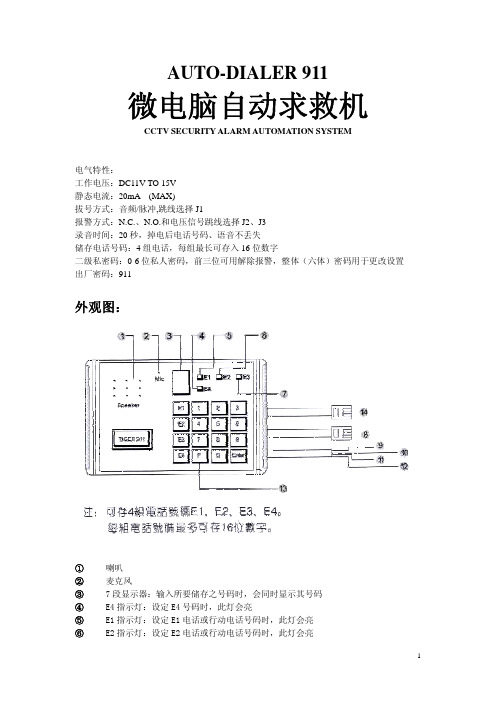
AUTO-DIALER 911微电脑自动求救机CCTV SECURITY ALARM AUTOMATION SYSTEM 电气特性: 工作电压:DC11V TO 15V 静态电流:20mA (MAX) 拔号方式:音频/脉冲,跳线选择 J1 报警方式:N.C.,N.O.和电压信号跳线选择 J2,J3 录音时间:20 秒,掉电后电话号码,语音不丢失 储存电话号码:4 组电话,每组最长可存入 16 位数字 二级私密码:0-6 位私人密码,前三位可用解除报警,整体(六体)密码用于更改设置 出厂密码:911外观图:① ② ③ ④ ⑤ ⑥喇叭 麦克风 7 段显示器:输入所要储存之号码时,会同时显示其号码 E4 指示灯:设定 E4 号码时,此灯会亮 E1 指示灯:设定 E1 电话或行动电话号码时,此灯会亮 E2 指示灯:设定 E2 电话或行动电话号码时,此灯会亮1⑦ ⑧ ⑨○ 10 11 12 ○○E3 指示灯:设定 E3 电话或行动电话号码时,此灯会亮 若设定密码时,E1,E2,E3 及 E4 指示灯会亮 接至电话接头 接至 DC12V 电源,桔色线(或红色)接正电压,咖啡色线(或黑色)接负电压 信号触发线,当接到 N.C.或 N.O.干接点时,不分极性,作为 DC12V 电压输入时,蓝 色线(或黄色)接正电压,绿色线接负电压13 ○P 按键可作为以下用途: 可储存 6 位数字作为密码 当使用于语音自动回报系统之总机时,可作为暂停时间,按 1 次,两秒;按 2 次,4 秒,以此类推.有此功能,即可自动打到分机14 ○接并联电话机设定触发信号及电话系统:① 打开背盖 ② 可看见印刷电路板上有 3 个跳线座 J1,J2,J3,依序并排. 可根据附图调整触发信号及电话系统③ 配合电信局设定电话为 TONE 或 PULSE 系统 将 J1 设定于"左边"即为 TONE 系统 将 J1 设定于"右边"即为 PULSE 系统 ④ 触发信号,请根据保全主机或感应器触发后输出接点, 选择适当之跳线座组合. (A)N.C.输入:将 J2 置于"左边" ,J3 亦置于"左边"2(B)N.O.输入:将 J2 置于"右边" ,J3 置于"左边" (C)电压输入:将 J2 置于"左边" ,J3 置于"右边" ⑤ 设定完成后,请将背盖盖上微电脑自动求救机 AUTO-DIALER 操作程序开机后先自检:自检完毕后进入工作状态,七段显示器的右下角小数点闪烁,若已存有信息,则收到报 警信号后 AUTO-DIALER 自动开始报警,如要设置或改变设置,按以下步骤可以储存,检 查电话号码,密码及录音,放音1 进入编程状态:先键入 P 然后输入私人密码(0-6 位)然后按下 注意:出厂密码为 911 例如:新机器未更改密码时进入编程状态操作如下: P ⑨ ① ① ENTER 如密码输入正确则显示一下 □ , 然后进入编程状态显示5若密码输入错误则显示一下 E ,退回工作状态,可按上述步骤重新输入2 储存第 1 组电话号码:在编程状态下,即显示 5 状态下: 例如电话号码为 93953399,则操作程序如下:AE19 ○3 ○5 ○3 ○3 ○9 ○9 ○ENTER键入 ENTER 时间始储存号码,如显示 □ ,则表示已正确存入, 然后返回 5 状态,如显示一下 E ,则表示未能正确存入, 机器会返回 5 状态,用户可重新操作,如要清除第 1 组电话号码时,只需在 5 状态下 键入 E1 后,直接键 ENTERB若先拨至语音自动播报总机,不透过接线员转接,再自动拨到分机,假设分机号码为 12,则储存方式如下: E1 9 ○ ENTER 3 ○ 5 ○ 3 ○ 3 ○ 9 ○ 9 ○ P ① ②C每按一次 P ,即暂停两秒,若按两次,则暂停四秒 (储存第 2,3,4 组电话号码方式均与第 1 组相同)3查询所预存之电话号码:3在编程状态下,即显示 5 状态下,按 3 键,此时显示匚,表示 CHECK,再按所欲查询之 E1,E2,E3,E4 或 PAUSE,显示器开始显示号码,其操作程序如下: 3 E1 或 E2 或 E3 或 E4 或 P 显示器开始显示所预存之电 话或私人密码,显示完毕后,即回单嘟响.4 A储存及播放求救语音信息:本机可储存 20 秒语音信息, 在编程状态下, 5 状态下, 1 键 即 按 (此时显示器显示 表示 RECORD) ,即可直接录音,其操作程序如下: ① 开始讲话,录音 回音嘟响 (20 秒后录音完毕,即自动停止. )┌B播放求救语音信息: 在编程状态下按 3 键再按 2 键,此时显示器显示 P , ( 表示 PLAY) , 即播放录入之语音信息,其操作程序如下: ③ ② 播放预存之 20 秒语音信息 回音嘟响 (20 秒后, 即自动停止)5 A储存密码及查询密码:储存密码: 可储存(0-6 位)私人密码,密码出厂时预设为 911.如私人密码为 714160,则操作程 序如下: 在编程状态下,即 5 状态下,键入 P ⑦ ① ④ ① ⑥ 0 ENTER ,即可听到回音嘟响声,表示输入完毕B查询密码: 在编程状态下,即 5 状态下,按 3 键,再按 P 键,显示器显示密码,其操作程序 如下: 键 ③ P 显示密码,显示完毕后,即回音嘟响声C如使用当中遗忘密码,则需打开背盖,加电到工作状态,按下(图一)所示的 RESET 键,则密码恢复为出厂密码 9116 A B C三种编程可选择报警方式:依次键入--5--0--enter:报警信号一旦触发,则连续拨号报警三个循环,中间可用密 码解除;详见第 8 条 依次键入--5--1--enter:报警信息号一旦触发,则连续拨号报警一个循环,中间可 用密码解除;详见第 8 条 依次键入--5--2--enter:报警信号保持触发才拨号,一旦报警信号中断,拨号报警也立4刻停止 检查键入--3--5:对应 A,B,C 分别显示 0,1,27 停止求救拨号:当 AUTO-DIALER911 被触发后,即根据原先储存之电话号码,拨号求救报警.想要随 时停止 AUTO-DIALER 拨号报警,可于显示器显示 □ 时,输入私人密码,以停止拨号 求救.假设密码为 1,2,3,当输入 1 2 3 时,显示器即由原来之显示 □ , 改为显示 1,2,3,如密码正确时,即发出嘟声解除报警.解除报警,只需键入前碱闰 密码即可,若密码不足三位,则需用"0"补齐 例如:密码为 1,2,操作程序为:显示 □ 状态下,键① ② 0 即可8 注意事项: A以上设定操作时,若欲变更原设定内容,只需编程状态下,即 5 状态下,重新操作同 一步骤,即可自动储存新内容B正确地按照说明书安装使用是十分重要的.在我们的销售活动中,经常会遇到一些新 客户在试用机器后说机器不正常, 当我们的工程师赶赴现场后, 才发现往往是客户电话 线接错或者是跳线设置不对, 以及报警方式没有设置. 所以我们针对这三点希望客户能 够特别注意: (1) 报警方式设置(详见使用说明书第 6 条) (2) 报警线触发方式跳线设置(详见设定触发信号及电话系统) (3) 电话线的连接(详见设定触发信号及电话系统)C常见故障排除法: (1)触发但拨不出号码:可能是电话线接反 (2)不触发:可能触发方式设置错误,即 J2,J3 跳线设置错误 (3)放音时噪音大:大多是由于拨号器的电源有问题 (4)拨号不停:是没有选择设置报警方式D不需主机直接用拨号器的方法: (1)选择对应的触发方式,911 可直接接探头,门磁,紧急按钮,电源开关而形成独 立的防盗系统 (2)布防:只需关掉电源,关门出去后,打开电源进入警戒状态 (3)撤防:在输入电话号码时,在电话号码前面按 8 次 P,即可延时 16 秒,每按一次 P 可延时 2 秒,进门后在 16 秒内按密码解除报警或关掉电源5。
- 1、下载文档前请自行甄别文档内容的完整性,平台不提供额外的编辑、内容补充、找答案等附加服务。
- 2、"仅部分预览"的文档,不可在线预览部分如存在完整性等问题,可反馈申请退款(可完整预览的文档不适用该条件!)。
- 3、如文档侵犯您的权益,请联系客服反馈,我们会尽快为您处理(人工客服工作时间:9:00-18:30)。
APPLICATIONS•THA for Differential ADCs •RF Demodulation Systems •Test Instrumentation•Digital Sampling OscilloscopesFEATURES•400 MHz Sampling Bandwidth •100 MHz Sampling Rate•Excellent Hold Mode Distortion-66 dB @ 50 MSPS (f IN = 25 MHz)-58 dB @ 100 MSPS (f IN = 50 MHz)•Track Mode Slew Rate: 700 V/µs•Low Power:120 mW Differential Mode75 mW Single-Ended Mode•Single +5 V Supply•Internal +2.5 V ReferenceBLOCK DIAGRAMGENERAL DESCRIPTIONThe SPT9110 is a single-to-differential track-and-hold ampli-fier. It can be operated as a single-end THA only or, in full configuration, as a single-to-differential THA. An internal reference provides the common-mode voltage for the single-to-differential output stage. The THA, inverter and reference have separate power supply pins so each can be optionally powered up and used.This device provides an analog designer with a low cost single-to-differential THA amplifier for interfacing differential and single-ended ADCs.The SPT9110 is offered in a 28-lead SOIC package in the industrial temperature range.Signal Processing Technologies, Inc.CLK NCLKAnalog In (V IN )Ref Out Out+Out-Ref InInvert In AAGNDAV CC (Ref)AV CC(INV)AV CC Invert In BELECTRICAL SPECIFICATIONSAV CC = +5.0 V, AGND = 0.0 V, Output Load = 1 k Ω and 10 pF, V IN = 2.0 Vp-p,Internal Reference, unless otherwise specified.TESTTEST SPT9110PARAMETERS CONDITIONS LEVELMINTYPMAX UNITSDC PerformanceGain ∆V IN = 2.0 Vp-p Single Ended Out+25 °CI 0.950.970.99V/V Full Temperature V 0.96V/V Differential Out +25 °CI 1.801.932.00V/V Full Temperature V 1.92V/V Offset V IN = +2.5 V Out++25 °CI -100±50+100mV Full TemperatureV 55mV Differential 1+25 °C, Ref In=Out+ CM I -15±5±15mV Full Temperature V 10mV Output Drive Capacity 2Full Temperature IV ±1±10mA Output Load at 10 pF Full Temperature V 1k ΩAnalog Input/Output Output Voltage Range Full Temperature VI 1.5 3.5V Input Capacitance +25 °C V 5pF Input Resistance+25 °CI 100140k ΩReference Voltage Output I 2.352.45 2.55V Reference Output Current 3+25 °CV ±100µAReference Voltage Tempco Full TemperatureV 75ppm/°CClock InputsInput Type/Logic Family V Differential PECLInput Bias Current+25 °C I 210µA Input Low Voltage (Differential)+25 °C I 3.33.5V Input High Voltage (differential)+25 °CI3.94.1VABSOLUTE MAXIMUM RATING (Beyond which damage may occur)1Note 1:Operation at any Absolute Maximum Ratings is not implied. See Electrical Specifications for proper nominal applied conditions in typical application.Note 2:Outputs are short circuit protected.Output Currents 2Continuous Output Current .................................±15 mATemperatureOperating Temperature ..............................-40 to +85 °C Junction Temperature.........................................+150 °C Lead, Soldering (10 seconds).............................+220 °C Storage .....................................................-65 to +150 °CSupply VoltagesAV CC Supplies .............................................-0.5 to +6 V Input VoltagesAnalog Input Voltage ....................................-0.5 to +6 V CLK, NCLK Input ..........................................-0.5 to +6 V Ref In ............................................................-0.5 to +6 V1Differential offset is specified with Ref In equal to the common mode output voltage of OUT+ and so includes the offset error of theinverter only.2This part is intended to drive a high impedance load. AC performance is degraded at ±10 mA. See the Typical Performance Graphs.3Ref Out has a typical output impedance of 1 k Ω and should be buffered for driving loads other than Ref In.AV CC = +5.0 V, AGND = 0.0 V, Output Load= 1 kΩ and 10 pF, V IN = 2.0 Vp-p,Internal Reference, unless otherwise specified.TEST TEST SPT9110PARAMETERS CONDITIONS LEVEL MIN TYP MAX UNITS Track Mode DynamicsBandwidth (-3 dB)+25 °CSingle Ended Out V220MHz Differential Out V140MHz Slew Rate 2.0 Vp-p Output Step+25 °CSingle Ended Out20 pF Load IV580V/µs Differential Out720 pF Load IV800V/µsInput RMS Spectral Noise Single Ended V 3.5nV/HzDifferential V13.0nV/Hz Track-to-Hold SwitchingAperture Delay+25 °C V250ps Aperture Jitter+25 °C V<1ps rms Pedestal Offset+25 °C IV±12mVFull Temperature V±12mV Hold Mode Dynamics4 (V IN = 1 Vp-p)Worst Harmonic5 MHz, 50 MSPS, Single-Ended T A = +25 °C IV-64-68dBT A = -40 °C to +85 °C V-64dB Worst Harmonic5 MHz, 50 MSPS, Differential T A = +25 °C IV-61-65dBT A = -40 °C to +85 °C V-63dB Worst Harmonic25 MHz, 50 MSPS, Single-Ended T A = +25 °C V-66dBT A = -40 °C to +85 °C V-63dB Worst Harmonic25 MHz, 50 MSPS, Differential T A = +25 °C V-64dBT A = -40 °C to +85 °C V-60dB Worst Harmonic50 MHz, 100 MSPS, Single-Ended T A = +25 °C IV-54-58dBT A = -40 °C to +85 °C V-54dB Worst Harmonic50 MHz, 100 MSPS, Differential T A = +25 °C IV-50-54dBT A = -40 °C to +85 °C V-50dB Sampling Bandwidth5 (-3 dB)+25 °C V400MHz V IN = 2.0 Vp-pHold Noise6 (RMS)+25 °C V300 x t H mV/s Droop Rate, V IN = +2.5 V+25 °C IV±40mV/µsFull Temperature IV±80mV/µs Feedthrough Rejection (50 MHz)Full Temperature V-65dB V IN= 2 Vp-p4.For hold times longer than 50 ns, the input common mode voltage may affect the hold mode distortion. (This is due to nonlineardroop that varies with VCM.) For optimal performance, SPT recommends that the held output signal be used within 50 ns of the application of the hold signal.5. Sampling bandwidth is defined as the -3 dB frequency response of the input sampler to the hold capacitor when operating in thesampling mode. It is greater than tracking bandwidth because it does not include the bandwidth of the output amplifier.6. Hold mode noise is proportional to the length of time a signal is held. This value must be combined with the track mode noise toobtain total noise.7. Optimized for hold mode performance and low power.TEST LEVEL CODESAll electrical characteristics are subject to the following conditions: All parameters having min/ max specifications are guaranteed. The Test Level column indicates the specific device test-ing actually performed during production and Quality Assurance inspection. Any blank sec-tion in the data column indicates that the speci-fication is not tested at the specified condition.TEST LEVELIIIIIIIVVVITEST PROCEDURE100% production tested at the specified temperature.100% production tested at T A = +25 °C, and sampletested at the specified temperatures.QA sample tested only at the specified temperatures.Parameter is guaranteed (but not tested) by designand characterization data.Parameter is a typical value for information purposesonly.100% production tested at T A = +25 °C. Parameter isguaranteed over specified temperature range.AV CC = +5.0 V, AGND = 0.0 V, R Load = 1 kΩ and 10 pF, V IN = 2.0 Vp-p, Internal Reference, unless otherwise specified.TEST TEST SPT9110PARAMETERS CONDITIONS LEVEL MIN TYP MAX UNITSHold-to-Track Switching8Acquisition Time to 0.1%+25 °C V 3.5ns1 V Output StepAcquisition Time to 0.025%+25 °C V 4.0ns1 V Output StepPower SuppliesSupply Voltage IV 4.755 5.25V Supply CurrentSingle Ended Output Mode9I1520mA Differential Output Mode I2430mA Power DissipationSingle Ended Output Mode9I75100mW Differential Output Mode I120150mW Power Supply Rejection Ratio+25 °C V44dB Single-Ended Output∆V CC = 0.5 V P-P8. Measured at the hold capacitor.9. Inverter powered down.TIMING SPECIFICATION DEFINITIONSACQUISITION TIMEThis is the time it takes the SPT9110 to acquire the analog signal at the internal hold capacitor when it makes a transition from hold mode to track mode. (See figure 1.) The acquisition time is measured from the 50% input clock transition point to the point when the signal is within a specified error band at the internal hold capacitor (ahead of the output amplifier). It does not include the delay and settling time of the output amplifier.Because the signal is internally acquired and settled at the hold capacitor before the output voltage has settled, the sampler can be put in hold mode before the output has settled.TRACK-TO-HOLD SETTLING TIMEThe time required for the output to settle to within 4 mV of its final value.APERTURE DELAYThe aperture delay time is the interval between the leading edge transition of the clock input and the instant when the input signal was equal to the held value. It is the difference in time between the digital hold switch delay and the analog signal propagation time.Figure 1 - Timing DiatramCLKNCLKOutputInputGENERAL DESCRIPTIONThe SPT9110 is a low cost 100 MSPS track-and-hold ampli-fier with single ended (75 mW) or differential output (120 mW).It consists of three components. The first is a single-ended track-and-hold amplifier (THA) with a 1.5 to 3.5 V input range and PECL clock inputs. The second is an inverting op amp with gain of -1 to provide the differential output (OUT-). The third component is a 2.5 V bandgap reference for the inverter.PARTITIONED POWER SUPPLY MANAGEMENTThree separate +5 V supply connections power the THA,inverting the op amp and bandgap reference. Unused com-ponents can be powered off to minimize power dissipation.The single-ended mode requires use of only the THA and output on the OUT+ pin. In this mode the reference and inverter may be powered down.The differential mode requires use of all three components (unless an external reference is supplied). The output is measured between OUT+ and OUT- in this mode.Figure 2 - Typical Output Response to Step Input500 m V / D i v i s i o n1.0 ns/DivisionFigure 3 - Typical Interface Circuit (Single-Ended Operational Design)TTL ClockNotes:1. Input signal is typically at a +2.5 V offset. The optional level-shift circuit may be eliminated if driving from a source that already provides for this offset.2. The device may be operated from -5 V supply on GND pins and 0 V on AV CC pins. All input and output pins will be shifted by -5 V . The use of an ECL level may be used to drive the clock inputs.3.V CC (ESD) is the high voltage for the ESD protection diodes and must be connected in all applications. NOTE: It should be tied to V CC (THA), not to V CC (INV).Figure 4 - Typical Interface Circuit (Differential Operational Design)TTL ClockNotes:1. Input signal is typically at a +2.5 V offset. The optional level-shift circuit may be eliminated if driving from a source that already provides for this offset.2. The device may be operated from -5 V supply on GND pins and 0 V on AV CC pins. All input and output pins will be shifted by -5 V . The use of an ECL level may be used to drive the clock inputs.3.V CC (ESD) is the high voltage for the ESD protection diodes and must be connected in all applications. NOTE: It should be tied to V CC (THA), not to V CC (INV).Single-Ended (OUT+) Hold Mode Distortion vs. Sample Rate507090110130150170190Sample Rate (MSPS)W o r s t H a r m o n i c (d B)Track Mode Bandwidth04080120160200Input Frequency (MHz)d B-6-4-2+2Reference Output Voltage vs. Temperature2.462.472.482.492.5Temperature (°C)V o l t s-50+50100Slew Rate vs. Temperature-50050100Temperature (°C)V /µs Differential Track Mode Distortion vs. Input FrequencyV= 1 V 0510152025303540Input Frequency (MHz)W o r s t H a r m o n i c (d B )Single Ended Track Mode Distortion vs. Input Frequency-35-40-45-50-55-60-65-70-751020304050607080Input Frequency (MHz)W o r s t H a r m o n i c s (d B )Track Mode Distortion vs. AC Coupled Resistive Loadf= 40 MHz, 1 V C = 10 pF-35-40-45-50-55-60-65-70025050075010001250150017502000R Load (Ohms)W o r s t H a r m o n i c (d B )Hold Mode Distortion vs. Temperaturef IN = 5 MHz, f S = 50 MSPS°CW o r s t H a r m o n i c (d B )-66-68-70-72-74-76-78-40-20020406080100Out+Out-Hold Mode Distortion vs. Temperaturef = 25 MHz, f = 50 MSPS-50-55-60-65-70°CW o r s t H a r m o n i c (d B )Hold Mode Distortion vs. Temperaturef IN = 50 MHz, f S = 100 MSPS-40-45-50-55-60-65-40-20020406080100°CW o r s t H a r m o n i c (d B )DC Parameters vs. TemperatureTemperature (°C)m V (m V /µs f o r D r o o p )GPACKAGE OUTLINE28-LEAD SOICSPT1111/12/98SPT9110PIN ASSIGNMENTSPIN FUNCTIONSNameFunctionAnalog In Single-ended analog input to the THA Invert InA Inverting input A to inverting amplifier resistor R1Invert InB Inverting input B to inverting amplifier resistor R2Out+Single-ended output of the THA Out-Output from the inverting amplifier CLK Noninverting differential PECL clock input NCLK Inverting differential PECL clock input Ref In Common-mode reference for the inverting amplifierRef Out Internal +2.5 V reference output AV CC (THA)Track-and-hold analog +5 V supply AV CC (INV)Inverter +5 V supplyAV CC (Ref)Internal reference +5 V supplyAV CC (ESD)+5 V supply for ESD protection diodes AGND (THA)Track-and-hold analog ground AGND (Cap)Hold capacitor analog ground AGND (Sub)Substrate analog ground AGND (INV)INVERTER analog ground AGND (Ref)Internal reference analog groundPART NUMBER TEMPERATURE RANGEPACKAGE TYPE SPT9110SIS-40 to +85 °C28L SOICORDERING INFORMATIONSignal Processing Technologies, Inc. reserves the right to change products and specifications without notice. Permission is hereby expressly granted to copy this literature for informational purposes only. Copying this material for any other use is strictly prohibited.WARNING - LIFE SUPPORT APPLICATIONS POLICY - SPT products should not be used within Life Support Systems without the specific written consent of SPT. A Life Support System is a product or system intended to support or sustain life which, if it fails, can be reasonably expected to result in significant personal injury or death.Signal Processing Technologies believes that ultrasonic cleaning of its products may damage the wire bonding, leading to device failure. It is therefore not recommended, and exposure of a device to such a process will void the product warranty.AGND (THA)AGND (THA)Analog In AGND (Sub)AGND (THA)AGND (Cap)AGND (THA)AGND (THA)Ref InRef Out AV CC (Ref)AGND (Ref)AGND (Sub)AGND (INV)12345678910111213142827262524232221201918171615Out+AV CC (THA)AV CC (INV)Invert InB Out-AV CC (INV)Invert InA AV CC (THA)AV CC (THA)AV CC (THA)AV CC (THA)NCLK CLK AV CC (ESD)元器件交易网。