在FBF背景下带反射边界条件的超对称tCJ模型的代数Bethe ansatz方法
二维弹性力学问题的光滑无网格伽辽金法

二维弹性力学问题的光滑无网格伽辽金法马文涛【摘要】计算效率低的问题长期阻碍着无网格伽辽金法(element-free Galerkin method,EFGM)的深入发展.为了提高EFGM的计算速度,本文提出一种求解二维弹性力学问题的光滑无网格伽辽金法.该方法在问题域内采用滑动最小二乘法(moving least square,MLS)近似、在域边界上采用线性插值建立位移场函数;基于广义梯度光滑算子得到两层嵌套光滑三角形背景网格上的光滑应变,根据广义光滑伽辽金弱形式建立系统离散方程.两层嵌套光滑三角形网格是由三角形背景网格本身以及四个等面积三角形子网格组成.为了提高方法的精度,由Richardson外推法确定两层光滑网格上的最优光滑应变.几个数值算例验证了该方法的精度和计算效率.数值结果表明,随着光滑积分网格数目的增加,光滑无网格伽辽金法的计算精度逐步接近EFGM的,但计算效率要远远高于EFGM的.另外,光滑无网格伽辽金法的边界条件可以像有限元那样直接施加.从计算精度和效率综合考虑,光滑无网格伽辽金法比EFGM具有更好的数值表现,具有十分广阔的发展空间.【期刊名称】《力学学报》【年(卷),期】2018(050)005【总页数】10页(P1115-1124)【关键词】无网格法;光滑应变;两层嵌套光滑三角形网格;计算效率【作者】马文涛【作者单位】宁夏大学数学统计学院,银川750021【正文语种】中文【中图分类】O241;O343引言为了克服有限元法面临的网格生成、重构以及其他与网格有关的困难,Belytschko 等[1]于1994年提出了无网格Galerkin法(element-free Galerkinmethod,EFGM).基于散乱数据的灵活插值、任意阶的光滑形函数、超收敛的数值结果以及在断裂力学问题中的成功表现,使EFGM很快成为了计算力学和工程领域众多研究者关注的热点,同时也掀起了无网格方法研究的热潮.到目前为止,已提出几十种无网格方法,并在偏微分方程数值解、金属冲压成形、高速冲击、裂纹动态扩展、流固耦合和局部化等诸多领域取得令人满意的成果[2-7].尽管无网格法种类繁多,但极少有数值方法能同时兼顾EFGM的灵活性、高精度和稳定性.因此,EFGM 仍然具有十分重要的研究价值和地位.然而,历经二十多年的发展,EFGM还仅仅是实验室高精度结果的生成者,并没有像有限元那样真正成为解决复杂工程问题的参与者.阻挠EFGM深入发展的根本原因是EFGM的计算效率非常低,严重影响了其处理实际问题的能力.其他类型的无网格法,如重构核质点法(reproducing kernel particle method,RKPM)[3],无网格局部Petrove-Galerkin法(meshless local Petrove-Galerkin method,MLPG)[4,8]、径向点插值无网格法(radial point interpolation meshless method,RPIM)[9]和一些结合式的无网格法[10]等,也存在着同样的问题.众所周知,EFGM采用滑动最小二乘法(moving least square method,MLS)建立近似函数及其导数,涉及矩阵求逆,计算量很大.其次,EFGM的形函数不具有Kronecher delta性质,导致本质边界条件施加困难.虽然Lagrange乘子法、耦合法和罚函数等[2,5]都能解决EFGM边界条件施加的问题,但同时也会带来诸如引入附加变量、改变系统矩阵性质等一系列新的问题,导致计算复杂度和计算时间的增加.另外,EFGM生成的是非多项式形式的近似解,要想获得稳定和高精度的弱形式数值解需要在每个背景网格中采用高阶高斯积分.Duan等[11]研究表明对于弹性力学问题,每个三角形背景积分网格中至少需要16个积分点才能使EFGM达到2阶精度.相比有限元法,EFGM的计算量要大得多.如何提高EFGM的计算效率成为近年来无网格法研究的热点和难点问题.为了提高EFGM的计算效率,Bessel等[12]提出了节点积分方案,也就是仅在近似节点上计算积分.该方法是不稳定的,在一些问题中会出现虚假的近奇异模态.Chen等[13-14]利用应变光滑技术,根据线性分片实验推导出Galerkin无网格法对应的积分约束,提出了稳定一致节点积分(stabilized conforming nodal integration,SCNI).SCNI很好地继承了节点积分的优势,同时完全避免了形成整体刚度矩阵时复杂形函数导数的计算过程.另外,SCNI能保证线性精度,而与无网格离散模式无关.为了弱化场函数近似的一致性要求,Liu及其团队[15-16]推广了应变光滑技术,提出了G空间理论和广义光滑Galerkin(GS-Galerkin)弱形式,建立了两类光滑数值方法的(weakened weak,W2)理论基础.这两类方法分别称为光滑有限元法(smoothed finite element method,S-FEM)和光滑点插值法(smoothed point interpolation method,S-PIM).S-FEM[17-20]的基本思想是:在有限元网格上创建的光滑区域内光滑化场函数导数,进而获得比传统有限元“更软”的光滑刚度矩阵,提高解的精度和收敛性.由于不需要计算形函数导数,避免了等参映射过程,因此S-FEM对畸形网格具有极强的适应性.S-PIM与S-FEM的基本原理相同,不同之处在于S-PIM使用多项式或径向基函数建立节点形函数.Liu[21]指出,S-FEM仅仅是S-PIM的特殊形式.Cui等[22]将MLS与GSGalerkin弱形式结合,提出了光滑伽辽金法.但与Galerkin无网格法相比,其计算精度较低.杜超凡等[23]采用S-PIM分析了旋转柔性梁的频率,得到固有频率的下界值.Liu等[24]在传统数值流形方法中引入光滑应变,改善其计算精度.Duan等[25-27]将SCNI中的线性积分约束推广到二阶情况,提出了二阶一致节点积分(quadratially consistent nodalintegration,QCI).QCI满足二阶精度,但为了求解形函数导数,必须在每个光滑区域内额外求解2个3×3的代数方程,计算代价并不小.Wang等[28]将三角形背景网格划分为两水平嵌套光滑区域,利用梯度光滑技术和Richardson外推法,提出了嵌套子域梯度光滑积分(NSGSI)算法.NSGSI算法将SCNI的精度提高到二阶.与高斯积分相比,NSGSI仅需要6个积分点,极大地提高了计算效率.为了得到二阶精度的数值算法,NSGSI必须使边界积分、外力项积分与刚度积分保持一致.显然,NSGSI的一致性要求大大降低了方法的灵活性.本文目的是提出一种能精确、高效地求解弹性力学问题的光滑无网格Galerkin法.基本思想是利用MLS近似位移场函数,在两层嵌套光滑子域上计算最优光滑应变,基于GS-Galerkin弱形式推导系统方程.两层嵌套网格由三角形背景积分网格以及连接三角形网格的三条边中点组成的4个三角形子网格构成.利用Richardson外推法,得到两层网格下对应的最优光滑应变.另外,为了通过线性分片试验条件,GS-Galerkin弱式要求在所有的边界上(包括自然边界和本质边界上)采用线性插值建立近似函数.因此,边界条件可以像有限元方法那样直接施加.1 MLS形函数在EFGM中,MLS方法被用于建立无网格形函数,具体形式为其中N(x)=pT(x)A−1(x)B(x)是MLS形函数;n是支持域内的节点数目;u=[u1u2L un]T为名义节点值向量,pT(x)为基函数向量,通常对于连续问题对于线弹性断裂问题其中(r,θ)为裂尖极坐标系下定义的位置参数.其他矩阵的定义分别为其中wI(x)=w(x−xI)为权函数,本文中使用3次样条权函数.2 系统离散方程2.1 光滑应变广义梯度光滑算子[13]作用于协调应变ε(x)其中为节点xc处的光滑应变,Φ为光滑函数,满足∫ΩcΦ(x;x−xc)dΩ =1. 简单起见,取其中为光滑区域Ωc的面积.将式(8)代入式(7),有其中nx和ny分别为光滑区域边界Γc上的单位外法线沿坐标轴方向的分量;u和v 分别为沿坐标轴方向的位移分量.将方程(1)代入方程(9),则光滑应变为其中称为光滑应变矩阵,具体形式为其中2.2 系统离散方程考虑二维线弹性固体力学问题,问题区域Ω内受体力b作用,边界Γt上受给定外力t 作用,边界Γu上满足u=.用光滑应变代替协调应变ε,得到GS-Galerkin弱式为将方程(1)和(10)代入方程(13)得其中为光滑刚度矩阵,由所有光滑区域组装得到.具体形式为式中,nsc为光滑区域总数.2.3 施加边界条件由以上推导可以看出,光滑应变运算不涉及任何形函数导数计算.因此,问题域内近似函数的不连续性并不会给光滑应变的计算带来任何困难.与标准Galerkin弱形式相比,形函数的一致性要求大大降低了.因此,在光滑无网格Galerkin法中,问题域内的点和边界上的点往往可以采用不同的近似形式.对于任何在问题域内的计算点均采用无网格近似函数;而对于任何在问题域边界上的计算点则采用线性插值函数.在边界上引入线性插值函数的目的是使光滑无网格法能够顺利通过线性分片试验,同时也使边界条件的施加变得和在有限元中一样容易.3 两层嵌套光滑积分网格为了计算光滑应变,光滑区域的选择至关重要.Liu等[21]基于背景积分网格本身、网格边界和网格顶点依次建立了不同类型的S-PIM.很显然,将背景三角形积分网格作为光滑区域是最简单、最直接的,不需要任何的附加工作.根据式(12)和Liu等[21]的研究结论,光滑区域内的光滑应变是个常数,导致了网格型光滑无网格法仅能达到线性精度,也就是说与传统三角形有限元法的精度相当.为了提高计算精度,进一步细分三角网格是非常有必要的.然而,细分过多的光滑子网格又会大大降低光滑无网格法计算效率.因此,寻找到最优的光滑网格细分方案是发展高效和高精度光滑无网格法的关键.本文提出两层嵌套光滑区域解决背景网格细分的问题.首先将问题域Ω离散为三角形背景积分网格.每个三角形网格称为父网格(见图1(a)).然后依次连结父网格的3条边的中点,形成4个等面积的子网格,如图1(b)所示.在每个光滑子网格边界上取一个高斯积分点,则根据方程(12),图1(a)所示的父网格对应的光滑应变矩阵为其中lJ和xJ分别是第J条边的边长和高斯积分点(即边界中点),nxJ和nyJ分别是第J条边单位外法线分别沿x,y方向的分量.组装所有父网格的光滑刚度矩阵可得由方程(17),可以很容易计算第m个子网格对应的光滑应变矩阵为其中Acm=Ac/4.组装所有子网格的光滑刚度矩阵为由图1可知每个光滑子网格的特征长度减小为父网格特征长度的一半,根据经典的Richardson外推法理论[28-29],方程(18)和(20)的最优线性组合可以生成更高精度的解.方程(21)是在同时考虑粗和细两种网格的基础上建立的,因此称为二层嵌套光滑区域.图1 两层嵌套三角形光滑网格(•场节点, 积分点,_高斯点Fig.1 Two-level nesting triangular smoothing cells(•node, grad e point,_Gauss point)在编程计算式(18)和式(20)的过程中,由于每个光滑积分区域的边界上采用1个积分点(线段中点)时,该点处的形函数值正好可以用线段两端点的形函数值的平均值表达.这样的话,每个三角形背景网格中需要3个顶点和3个线段中点,总共6个积分点即可.4 数值算例为了研究本文方法的精度,L2范数下的位移误差和能量误差分别定义为式(22)、式(23)中,ue,un分别代表位移精确解和数值解;εe,εn分别代表应变精确解和数值解.为了书写的方便,使用父网格(1个网格)、4个子网格以及嵌套网格(1个网格及其4个子网格)的3种光滑Galerkin无网格法分别简记为FSMM,SSMM和NSMM.EFGM采用拉格朗日乘子法施加位移边界条件.笔者根据Duan等[11]的研究结论,在EFGM的每个三角形背景积分网格中采用16个高斯积分点.上述4种方法,在悬臂梁、无限大开孔平板和双连拱隧道算例中均使用线性基函数(见式(2)),在含中心裂纹的无限大板算例中则使用内部扩展基函数(见式(3)).4种方法都在同一台电脑(处理器:Intel(R)Core(TM)*******************)上采用matlab语言编程实现.4.1 悬臂梁如图2所示,悬臂梁左侧固定,右侧受剪切作用.在平面应力条件下,解析解[30]为图2 悬臂梁Fig.2 The cantilever beam其中 I=D3/12.梁的材料参数取为E=3×107MPa,v=0.3,P=1000 N.在梁上分别布置17×5,33×9和65×17个节点.图3比较了3种节点分布下5种方法求解悬臂梁问题时的位移误差.可以看出,FSMM与传统三角形FEM的精度几乎一致;SSMM的精度要高于FSMM的;而NSMM与EFGM的计算精度几乎一致,且远远高于其他3种方法.图3 悬臂梁问题的位移误差比较Fig.3 Displacement error comparison for the cantilever beam problem图4则给出了5种方法的能量误差比较.从图4可以看出,无网格法的精度都要高于FEM的,NSMM比FSMM和TSMM的精度高;虽然EFGM的精度高于3种光滑无网格Galerkin法的,但其收敛率却最低.这些结论很好地证明了随着光滑区域的增加,积分点的个数也随之增加,光滑无网格Galerkin法的计算精度会逐步升高.图4 悬臂梁问题的能量误差比较Fig.4 Energy error comparison for the cantilever beam problem图5给出了5种方法的CPU时间比较.可以看出,在节点分布相同时,FSMM的计算耗时比FEM略长;NSMM与SSMM的计算耗时相当,比FSMM的要长,但要远远短于EFGM的.从精度和效率两个方面综合考虑,NSMM是5种方法中表现最好的. 图5 悬臂梁问题的CPU时间比较Fig.5 CPU time comparison for the cantilever beam problem4.2 无限大开孔平板设一无限大平板,中心开有半径为a的圆孔,在远离孔心的位置沿水平方向受σ0=1 Pa的轴向拉伸作用.该问题的解析解[30]为其中,r,θ为以孔心为原点的极坐标考虑对称性,仅取平板右上角四分之一进行数值计算,见图6.设板长、宽均为b=5 cm,圆孔半径a=1 cm,弹性模量E=30 MPa,泊松比v=0.3.在底部和左侧边界上分别给定位移边界条件uy(x,0)=0和ux(0,y)=0;在板右端(x=b)和上部(y=b)边界按精确解施加自然边界条件.在平板模型上分别布置9×9,17×17和33×33个节点.图7∼图9分别给出了3种节点分布下不同方法对应的位移误差、能量误差和花费的CPU时间.从图7∼图8可以看出,本文提出的NSMM的精度与EFGM的基本相同的,要高于其他几种方法.图9再次证明了NSMM的效率要远远高于EFGM.图6 无限大开孔平板模型Fig.6 Model of the infinite plate with a circle hole图7 无限大开孔平板问题的位移误差比较Fig.7 Displacement error comparison for the problem of the infinite plate with a circle hole图8 无限大开孔平板问题的能量误差比较Fig.8 Energy error comparison for the problem of the infinite plate with a circle hole图9 开孔平板问题的CPU时间比较Fig.9 CPU time comparison for the problem of the infinite plate with a circle hole4.3 含中心裂纹的无限大板考虑一无限大板,中心包含一长度为2a的直裂纹,在远端受单向拉应力σ作用,见图10.计算过程中,计算区域ABCD取为10 mm×10 mm,a=100 mm;E=300 MPa,v=0.3,σ =1 MPa;在计算区域内均匀分布20×20个节点.分别采用EFGM,FSMM,SSMM和NSSM求解该问题.图11为4种方法计算得到的裂纹前端应力与精确解[31]的比较.可以看出,FSMM,SSMM和NSSM的应力曲线呈现依次逼近解析解的特征,说明随着光滑区域数量的增加,光滑Galerkin无网格法的精度也随之提高;NSMM和EFGM的计算结果与解析解吻合得非常好.图10 含中心裂纹的无限大板的几何结构和载荷Fig.10 Geometry and loads of infinite plate with a center crack图11 裂纹前端(r>0,θ=0)应力比较Fig.11 Stresses comparison ahead of the crack tip(r>0,θ=0)for the near-tip crack4.4 双连拱隧道设有一双连拱形隧道,基本结构如图12所示.分别采用本文方法(NSMM)和EFGM,按照平面应变假设分析隧道围岩和衬砌在自重作用下的变形和应力分布.计算过程中,围岩及混凝土力学参数见表1;三角形背景网格划分见图13.将单元角点作为节点,共5145个背景单元,2729个节点.根据对称性,模型左侧边界上各点处x方向固定,y 方向自由,而在下边界上各点x方向自由,y方向固定.图12 双连拱隧道结构Fig.12 The structure sketch of twin-arched tunnel表1 材料参数性能Table 1 Parameters of material propertyMaterial typeE/GPa v Bulk density/(kN ·m−3)III type surrounding rock 2 0.25 22 surrounding rock of reinforced area 2.6 0.2 23 lining(C25) 28.5 0.2 25 shotcrete(C25) 28.5 0.2 23 backfilling concrete(C10) 18.5 0.2 22图13 三角形背景网格和边界条件Fig.13 Triangular background mesh and boundary conditions图14 第一主应力图Fig.14 The first principal stress图15 第二主应力Fig.15 The second principal stress图14和图15分别给出了由NSMM的计算结果绘制的第一、第二主应力云图.由图14可以看出,拱圈顶部附近、仰拱拱底附近、边墙和中墙基础底部都出现了较大的拉应力.从图15可以看出,几个形状突变较为明显的区域,由于应力集中导致了较大压应力的出现.图14和图15的结论与文献[32]的结论是一致的.NSMM与EFGM的计算结果十分接近,但EFGM的CPU用时为197.48 s,而本文方法仅为35.44 s,进一步说明本文方法具有极高的计算效率.5 结论EFGM是一种十分重要的无网格数值方法,但其计算效率低的问题长期困扰着研究工作者.本文基于广义梯度光滑技术,提出了光滑无网格Galerkin法,试图解决这一难题.本文方法的基本思想是利用MLS近似位移场函数,在两层嵌套光滑子域上计算最优光滑应变,基于GS-Galerkin弱形式推导了系统方程.两层嵌套网格由三角形背景积分网格以及连接三角形网格的3条边中点组成的4个三角形子网格构成.利用Richardson外推法,得到两层网格下对应的最优光滑应变.几个数值算例验证了本文方法的精度和计算效率.从这些数值结果可以看出,本文方法具有以下优势: (1)计算效率高.本文方法充分利用了光滑梯度技术,将区域积分转化为区域边界积分,完全避免了形成整体刚度矩阵时复杂形函数导数计算.因此,极大地提高了的计算效率.数值结果表明,在节点分布相同的情况下,NSMM比EFGM花费的计算时间要少的多.(2)计算精度高.FSMM类似SCNI,仅有线性精度:SSMM将FSMM的光滑区域细分为4个子区域,相当于引入了更多的积分取样点,因此SSMM比FSMM的精度更高:Richardson外推法又从理论上保证NSMM比FSMM和SSMM二者的精度更高.4个数值算例证明了NSMM具有几乎和EFGM相同的计算精度.(3)易于施加边界条件.本文方法在实现过程中,域内计算点采用MLS近似,而在域边界上的计算点则采用线性插值.一方面,本文方法可以自然满足线性分片试验;另一方面,边界条件的施加过程就和FEM一样了.这样,无网格边界条件施加困难的问题也就迎刃而解了.综上所述,本文提出的光滑Galerkin无网格法,既保持了无网格法的精度高的优势,又极大地减少了计算用时,同时也解决了施加边界条件的难题,具有十分广阔的发展空间.将本文方法进一步推广到结构动力学分析、大变形分析以及裂纹动态扩展等问题将是未来的研究方向.参考文献【相关文献】1 Belytschko T,Lu YY,Gu L.Element-free Galerkin methods.International Journal for Numerical Methods in Engineering,1994,37:229-2562 Belytschko T,Kronggauz Y,Organ D,et al.Meshless methods:An overview and recent putational Methods in Applied Mechanics and Engineering,1996,139:3-473 Liu WK,Jun S,Zhang YF.Reproducing kernel particle methods.International Journal for Numerical Methods in Fluids,1995,20:1081-11064 Atluri SN,Shen SP.The Meshless Local Petrov-Galerkin(MLPG)Method.Tech Science,20025 Nguyen VP,Rabczuk S,Bordas S,et al.Meshless Methods:A review and computer implementation aspects.Mathematics and Computers in Simulation,2008,79:763-8136 Rabczuk T,Bordas S,Zi G.A three-dimensional meshfree method for continuous multiplecrack initiation,nucleation and propagation in statics andputational Mechanics,2007,40:473-4957 马文涛,许艳,马海龙.修正的内部基扩充无网格法求解多裂纹应力强度因子.工程力学,2015,32(10):18-24(Ma Wentao,Xu Yan,Ma Hailong.Solving stress intensity factors of multiple cracks by using a modified intrinsic basis enriched meshless method.Engineering Mechanics,2015,32(10):18-24(in Chinese))8 Atluri SN,Zhu T.A new meshless local Petrov-Galerkin(MLPG)approach in computational putational Mechanics,1998,22:117-1279 Wang JG,Liu GR.A point interpolation meshless method based on radial basis function.International Journal for Numerical Methods in Engineering,2002,54:1623-1648 10 杨建军,郑健龙.无网格局部强弱法求解不规则域问题.力学学报,2017,49(3):659-666(Yang Jianjun,Zheng Jianlong.Meshless local strong-weak(MLSW)method for irregular domain problems.Journal of Theoretical and Applied Mechanics,2017,49(3):659-666(in Chinese)) 11 Duan QL,Li XK,Zhang HW,et al.Second-order accurate derivatives and integration schemes for meshfree methods.International Journal for Numerical Methods in Engineering,2012,92:399-42412 Beissl S,Belytschko T,Nodal integration of the element-free Galerkin puter Method in Applied Mechanics and Engineering,1996,139(19):49-6413 Chen JS,Wu CT,Yoon S,et al.A stabilized conforming nodal integration for Galerkin meshfree methods.International Journal for Numerical Methods inEngineering,2001,50:435-46614 Chen JS,Yoon J,Wu CT.Nonlinear version of stabilized conforming nodal integration for Galerkin meshfree methods.International Journal for Numerical Methods in Engineering,2002,53:2587-261515 Liu GR.A generalized gradient smoothing technique and smoothed bilinear form for Galerkin formulation of a wide class of computational methods.International Journal of Computational Methods,2008,5(2):199-23616 Liu GR,Zhang GY.A normed G space and weaked weak(W)formulation of a cell-based smoothed point interpolation method.International Journal of Computational Methods,2009,6(1):147-17917 Liu GR,Nguyen TT,Smoothed Finite Element Method.Boca Raton:CRC Press,201018 Liu GR,Zhang GY.Smoothed Point Interpolation Methods:G Space Theory and Weakened Weak Forms.New Jersey:World Scientific,201319 Bordas PAS,Rabczuk T,Hung NX,et al.Strain smoothing in FEM and puters and Structures,2010,88:1419-144320 Chen L,Rabczuk T,Bordas PAS,et al.Extended finite element method with edge-based strain smoothing(ESm-XFEM)for linear elastic crack putational Methods in Applied Mechanics and Engineering,2012,209-212:250-26521 Liu GR,Smoothed finite element methods(S-FEM):An overview and recent developments.Arch Computat.Methods Eng,2018,25:397-43522 Cui XY,Li GY.Smoothed Galerkin methods using cell-wise strain smoothing technique.Engineering Analysis with Boundary Elements,2012,36:825-83523 杜超凡,章定国.光滑节点插值法:计算固有频率下界值的新方法.力学学报,2015,47(5):839-847(Du Chaofan,Zhang Dingguo.Node-based smoothed point interpolation method:A new method for computing lower bound of natural frequency.Chinese Journal of Theoretical and Applied Mechanics,2015,47(5):839-84724 Liu F,Yu CY,Yang YT.An edge-based smoothed numerical manifold method and its application to static,free and forced vibration analyses.Engineering Analysis with Boundary Elements,2018,86:19-3025 Duan QL,Wang BB,Gao X,et al.Quadratically consistent nodal integration for second order meshfree Galerkin putational Mechanics,2014,54:353-36826 Wang BB,Duan QL,Shao YL,et al.An efficient nodal integration with quadratic exactness for three-dimensional meshfree Galerkin methods.Engineering Analysis with Boundary Elements,2016,70:99-11327 邵玉龙,段庆林,李锡夔等.功能梯度材料的二阶一致无网格.工程力学,2017,34(3):15-21(Shao Yulong,Duan Qinglin,Li Xi kui,et al.Quadratically consistent meshfree method for functionally graded materials.Engineering Mechanics,201734(3):15-21(in Chinese))28 Wang DD,Wu JC.An efficient nesting sub-domain smoothing integration algorithm with quadratically exactness for Galerkin meshfree puter Methods in Applied Mechanics and Engineering,2016,298:485-51929 Brezinski C,Zaglia MR.Extrapolation Methods:Theory and Practice.North-Holland,199130 Timoshenko SP,Goodier JN.Theory of Elasticity,3rd edition.New York:McGraw-Hill,198731 Williams ML.On the stress distributions at the base of a stationary crack.Journal of Applied Mechanics,1957,24:109-11332 徐荣桥.结构分析的有限元法与MATLAB程序设计.北京:人民交通出版社,2006(Xu Rongqiao,Finite Element Method and Matlab Programing Design for Structural Analysis.Beijing:China Communications Press,2006(in Chinese))。
整个超构透镜器件的仿真边界条件

整个超构透镜器件的仿真边界条件下载提示:该文档是本店铺精心编制而成的,希望大家下载后,能够帮助大家解决实际问题。
文档下载后可定制修改,请根据实际需要进行调整和使用,谢谢!本店铺为大家提供各种类型的实用资料,如教育随笔、日记赏析、句子摘抄、古诗大全、经典美文、话题作文、工作总结、词语解析、文案摘录、其他资料等等,想了解不同资料格式和写法,敬请关注!Download tips: This document is carefully compiled by this editor. I hope that after you download it, it can help you solve practical problems. The document can be customized and modified after downloading, please adjust and use it according to actual needs, thank you! In addition, this shop provides you with various types of practical materials, such as educational essays, diary appreciation, sentence excerpts, ancient poems, classic articles, topic composition, work summary, word parsing, copy excerpts, other materials and so on, want to know different data formats and writing methods, please pay attention!超构透镜器件仿真边界条件的探究在超构透镜器件的设计与仿真过程中,正确设置仿真边界条件至关重要。
施瓦茨反射定理
施瓦茨反射定理施瓦茨反射定理(Schwarz's reflection principle)是数学分析中的典型应用之一,它为解析函数在实轴上的延拓提供了便利。
这个定理得名于德国数学家赫尔曼·瓦尔特·施瓦茨(Hermann Amandus Schwarz),他在19世纪末提出了这一定理。
在数学分析、复变函数论和物理学中,施瓦茨反射定理都扮演着重要的角色。
施瓦茨反射定理的基本思想是根据解析函数的性质,在复平面上找到一种方式,使得函数对应的解析函数沿着实轴上的实部对称。
具体来说,对于任意给定的解析函数f(z),如果满足f(z)在实轴上的实部连续,则可以通过关于实轴的对称方式,将其延拓到复平面上实轴下方。
施瓦茨反射定理可以简单地表示为:如果f(z)是定义在上半平面的解析函数,并且在实轴上连续到一致性的实函数g(x),那么利用关于实轴的对称,可以得到在下半平面的解析函数f*(z)。
这个对称通过以下公式进行表示:f*(z) = g*(z) = g(z*),其中z*是z的复共轭。
施瓦茨反射定理的应用非常广泛。
一方面,它广泛应用于复变函数论中,用于求解一些特殊函数的解析延拓问题。
例如,利用施瓦茨反射定理可以将黎曼ζ函数(Riemann zeta function)在实轴上的定义延拓到复平面上,进而研究复平面上的ζ函数的性质。
另一方面,施瓦茨反射定理可以应用于物理学中的电磁学问题,特别是在求解边值问题中。
例如,可以利用施瓦茨反射定理解决静电平面问题和静磁平面问题。
施瓦茨反射定理的证明主要基于复变函数的性质和解析函数的连续性。
首先,通过对函数f(z)的实部进行幅角补偿,可以得到一个在实轴上连续的实函数g(x)。
然后,利用解析函数的性质,可以推导出实轴上的实函数g(x)在复平面上具有对称性,即其复共轭g*(z)也是解析函数。
最后,由于f(z)在上半平面是解析函数,利用解析函数的唯一性原理,可以得到f(z)和g*(z)在下半平面上也是解析函数。
冯慈璋-电磁场(第二版)课后答案_第1一6章习题

1
试求(1)α1和β1 (2)反射系数Γ (3)反射波电场Erx (4)透射波电场Etx
解:(1)由题知1为自由空间,2为损耗媒质
1 0
1 0 0 0.33rad / m
(2)
2 2 2
2 2 2c 334e j 31.7 2 2c 2 j 2 c 1 0.29e j103 2 c 1 8 8 E E cos 10 t z 29cos 10 t 0.33 z 103 V / m (3) rx im 1
第六章 习题
6.1有一频率为100MHz、沿y方向极化的均匀平面波从空气(x<0区域 中垂直入射到位于x=0的理想导体板上,设入射波电场Ei的振幅为 10V/m, 试求(1)入射波电场Ei和磁场Hi的复矢量 (2)反射波电场Er和磁场Hr的复矢量 (3)合成波电场ቤተ መጻሕፍቲ ባይዱ1和磁场H1的复矢量 (4)距离导体平面最近的合成波电场E1为零的位置 (5)距离导体平面最近的合成波电场H1为零的位置
2 8 9 1.27 10 cos 5 10 5 10 3.33 ˆ H1 y 1.49 103 cos 5 108 5 109 3.33
1
1
ˆ10.4 103 y
A/ m
6.17z<0为自由空间,z>0区域中为导电媒质(媒质2的σ2=0.004S/m、 ε=20pF/m、μr=5μH/m),均匀平面波从媒质1垂直入射到分界 面上。 E 100e 1z cos 108 t z V / m
解:(1) 2 f 2 108
rad / s rad / m
超对称Sinh-Gordon模型的边界反射因子
fermionic
partners
within
the
N=1
supersymmetric
sine-Gordon
theory
have
been
[7]
conjectured .
2
高 能 物 理 与 核 物 理 ( HEP & NP)
第 26 卷
In this paper, we will examine supersymmetric sinh-Gordon ‘theory restricted to a half-line by integrable boundary conditions. The paper is organised as follows: in section two, we summarise the main features of the model and describe the boson and fermion propagators; the construction of the supersymmetric reflection factors for the two allowed boundary conditions are presented in section three together with reasons for deviating from the suggestions made by Moriconi and Schoutens; in the final section we check the fermion reflection factors agree with the perturbation expansion up to second order in the bulk coupling constant.
布拉格反射公式范文

布拉格反射公式范文一、布拉格反射公式的推导当X射线或中子入射到晶体上时,将会与晶体中的原子发生相互作用。
这种相互作用会导致X射线或中子产生散射,即在不同的角度发生反射或者散射。
为了描述这种现象,可以用布拉格反射公式来表示。
考虑一个晶体,假设一个入射的X射线或中子波长为λ,入射角为θ。
当入射波束与晶体中的晶面相互作用时,会发生反射或散射。
我们可以将入射波以及反射波投影到晶面上,这样可以得到两个相应的向量。
根据几何关系,可以将晶面上的两个向量拆分为垂直于晶面和平行于晶面两个分量。
垂直于晶面的分量与晶面上的向量长度相等,平行于晶面的分量与前一分量长度相等。
根据矢量和的关系,可以得到入射波与反射波长度相等的矢量和。
则入射波长度可以表示为:λ = Lcosθ + dcos(180-θ-i)其中,L为入射波在垂直于晶面方向的分量长度,d为晶面间距,i为反射角。
同时,可以得到入射波的水平分量长度:Lsinθ = dcosi。
综上所述,可以得到布拉格反射公式:nλ = 2dsinθ其中,n为整数,表示反射的阶次。
二、布拉格反射公式的应用1.衍射仪器2.材料表征通过布拉格反射公式,可以测定晶体中的晶面间距,从而获得晶体中的晶胞参数。
这对于材料科学研究非常重要。
例如,通过测量材料的晶面间距,可以了解材料的结晶度、晶体尺寸以及晶格畸变等。
这为材料的性能分析和优化提供了依据。
3.结构分析布拉格反射公式也被广泛应用于结构分析领域。
通过衍射实验,可以得到X射线或中子的衍射图样。
根据布拉格反射公式,可以将衍射图样与晶体结构进行对应,从而确定晶体的原子位置和结构。
这对于理解和研究材料的晶体结构、相变等现象具有重要意义。
4.晶体学研究布拉格反射公式是晶体学研究领域的基础。
晶体学通过测定晶体的晶胞参数、晶面角以及晶格常数等,来研究晶体的结构和性质。
布拉格反射公式提供了一种重要的实验手段,可以用于测定晶体的重要结构参数,并且可以通过晶体学理论继续研究晶体的更多特性。
《非傅里叶热传导模型的H~1-Galerkin混合连续时空有限元方法》范文
《非傅里叶热传导模型的H~1-Galerkin混合连续时空有限元方法》篇一非傅里叶热传导模型的H^1-Galerkin混合连续时空有限元方法一、引言在科学与工程计算中,热传导现象是一个基本而重要的研究课题。
传统的傅里叶热传导模型虽然能解释许多热传导现象,但在某些极端或复杂环境下,如纳米材料、微尺度系统以及高频率变化的热流环境中,其模型不再适用。
因此,非傅里叶热传导模型逐渐成为研究的热点。
为了更准确地模拟和解决这些复杂问题,本文提出了一种基于H^1-Galerkin混合连续时空有限元方法(H^1-Galerkin Hybrid Continuous Space-Time Finite Element Method)来研究非傅里叶热传导模型。
二、非傅里叶热传导模型非傅里叶热传导模型是在传统的傅里叶热传导模型基础上发展起来的,它考虑了热波传播的延迟效应和热流的不连续性。
在非傅里叶热传导模型中,温度的变化不仅取决于温度梯度,还与热流的传播速度和方向有关。
这使得我们能够更准确地模拟和分析复杂的热传导现象。
三、H^1-Galerkin混合连续时空有限元方法H^1-Galerkin混合连续时空有限元方法是一种有效的数值求解方法,它结合了时空有限元和混合有限元的特点,能够在连续时间和空间上求解偏微分方程。
这种方法可以处理复杂的几何形状和非线性问题,适用于求解非傅里叶热传导模型。
在H^1-Galerkin混合连续时空有限元方法中,我们将空间和时间看作一个统一的维度,采用有限元方法对时间进行离散化处理。
在每个时间步长内,通过求解Galerkin方程来获得温度的近似解。
同时,我们使用混合有限元的方法来处理未知的边界条件和源项。
四、应用H^1-Galerkin混合连续时空有限元方法求解非傅里叶热传导模型在应用H^1-Galerkin混合连续时空有限元方法求解非傅里叶热传导模型时,我们首先将求解区域划分为一系列的子区域(即有限元),然后在每个子区域内进行离散化处理。
高等电磁场理论第三章课后作业

第三章3-2 在Coulomb 规范条件下,矢量位和标量位满足微分方程: (1) (2)可得:又由电荷守恒定律可知:0t J ρ∂∂∇∙+=(r)J j ωρ∴∇∙=-所以, (3)将(3)带入(1)可得:即证明之 3-4 (1)电流元产生的电磁场求解电Hertz 位满足其中(r)(r)e J P j ω=s=I J dS∙⎰又所以可得:电Hertz 位与场量之间的关系为:2(r)j (r)(r)(r)(r)e e e e eH E ωεωμε=∇⨯∏=∇∇∙∏+∏22()()()j ()k μωμε∇+=-∇ΦA r A r J r +r ()()ρε∇Φ=-2r r ()()4V dV ρπε''Φ='-⎰r r |r r |1()()j 4V dV ωπε'∇⋅'Φ=-'-⎰J r r |r r |22()()()()4Vk dV μμπ'∇⋅'∇+=--∇'-⎰J r A r A r J r |r r |e 2e2e()()()k ε∇+=-P r Πr Πr e j ||j ||e j ()11()4||j 4||j 4k k krzz Vl e Ie Il dV dz er επωεπωεπ''-----''==≈''--⎰⎰r r r r P r Πr e e r r r r代入可得: 其中cos e sin z r e e θθ-θ=(2)磁流元产生的电磁场求解 由对偶原理可得:3-13 y11,εμZ22,εμ如图所示,由边界条件 1212(E )0(H H )Sn E n J⨯-=⨯-=e e j j 2j 221()j ()j j 4sin j 1cos sin 44z kr kr krr Il r Il e e k Il e r r kr k r θφωεωεωεπθθθππ---⎛⎫=∇⨯=∇⨯ ⎪⎝⎭⎛⎫⎛⎫=∇⨯-=+ ⎪ ⎪⎝⎭⎝⎭H r Πr e e e e e e33j j 22332233()()j cos j 1sin 1j 1j j 24kr krr k Il k Il e e k r k r kr k r k r θωεθθπωεπωε--∇⨯=⎛⎫⎛⎫=-+--++ ⎪ ⎪⎝⎭⎝⎭H r E r e e m mmj m j j 2m j 221()j ()j j 4sin j 1cos sin 44kr z kr kr krr I l e r I l e e k I l er r kr k r θφωμωμωμπθθθππ----⎛⎫=-∇⨯=-∇⨯ ⎪⎝⎭⎛⎫⎛⎫=-∇⨯-=-+ ⎪ ⎪⎝⎭⎝⎭E r Πr e e e e m m33j j 22332233()()j cos j1sin 1j 1j j 24m m kr kr rk I l k I l e e k rk r kr k rk r θωμθθπωμπωμ--∇⨯=-⎛⎫⎛⎫=-+--++ ⎪ ⎪⎝⎭⎝⎭E r H r e e又因为(y)z J e I =δ所以可知磁场H 方向为x 方向,电场E 方向为z 方向。
背景偏振光谱二向反射分布函数建模分析
背景偏振光谱二向反射分布函数建模分析**陈超**,赵永强,程咏梅,潘泉,杨铁恒(西北工业大学自动化学院,陕西西安710072)摘要:通过分析偏振二向反射分布函数(BRDF)与实验探测角、波长间的关系,提出偏振度分量的多项式模型来定量化描述偏振度分量;强度分量采用现有的半经验模型,在可见光范围内(400~720nm)实现偏振光谱BRDF 建模,并将模型输出的结果和实验测量值进行分析比较。
结果表明,对于土壤等各向性质较为均匀的背景,采用本文模型能较好地达到精度要求,因而可以将有限实验观测条件下测量得到的少数偏振光谱BRDF扩展到2P空间范围内,得到任意入射及观测条件下的偏振光谱BRDF值,且具有简单、计算量小等优点。
关键词:偏振二向反射分布函数(BRDF);强度分量;偏振度分量;多项式模型中图分类号:TN247文献标识码:A文章编号:1005-0086(2009)03-0369-05Mod els valid ation and an alysis of spectrop larm atric B RD F for soilCHEN Chao**,ZHAO Yong-qiang,CH ENG Yong-mei,PAN Quan,YANG Tie-heng (College of Automation,Northwestern Polytechnical University,Shanxi Xi c an710072,China)Ab st ract:T he outdoor measurement of the polarimatic bidirec t ional reflec t ance distribution function (pBRDF)and the validation of the models are mainly introduce d and then the relationship between the experimental values and the degrees of angles of observation is analyzed in de t ail.The given conditions of pBRDF intense component are modeled through the geometry of backgrounds and the e xperime ntal re-sult s using the linear empirical models.And for modeling of DoP component,t he polynomial is proposed through analyzing the experimental data,and then the predic at ed values are compare d with the exper-i me ntal values.Exc ellent agreement between the me asure d and the predicated is demonstrated.Therefore the models adopt e d in this paper could take place the experiment to get the pBRDF of arbitrary parame-t e rs for further study on some case.Ke y wor ds:polarimatric bidirec t ional reflec t ance distribution function(BRDF);intense component;DoP component;polynomial model1引言地球表面或大气中的目标在反射、散射、透射及发射电磁辐射的过程中,由于物体表面结构、内部构成以及入射角度的不同,反射电磁波不仅强度发生变化,而且会产生由它们自身性质决定的偏振态变化。
哈佛大学Capasso教授小组研究用界面位相突变的超材料实现超常折射的论文
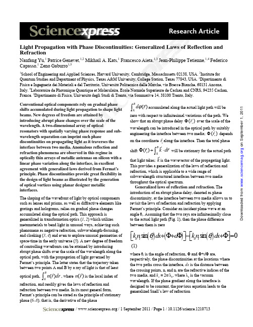
Conventional optical components rely on gradual phase shifts accumulated during light propagation to shape light beams. New degrees of freedom are attained by introducing abrupt phase changes over the scale of the wavelength. A two-dimensional array of optical resonators with spatially varying phase response and sub-wavelength separation can imprint such phase discontinuities on propagating light as it traverses the interface between two media. Anomalous reflection and refraction phenomena are observed in this regime in optically thin arrays of metallic antennas on silicon with a linear phase variation along the interface, in excellent agreement with generalized laws derived from Fermat’s principle. Phase discontinuities provide great flexibility in the design of light beams as illustrated by the generation of optical vortices using planar designer metallic interfaces. The shaping of the wavefront of light by optical components such as lenses and prisms, as well as diffractive elements like gratings and holograms, relies on gradual phase changes accumulated along the optical path. This approach is generalized in transformation optics (1, 2) which utilizesmetamaterials to bend light in unusual ways, achieving suchphenomena as negative refraction, subwavelength-focusing,and cloaking (3, 4) and even to explore unusual geometries ofspace-time in the early universe (5). A new degree of freedomof controlling wavefronts can be attained by introducingabrupt phase shifts over the scale of the wavelength along theoptical path, with the propagation of light governed byFermat’s principle. The latter states that the trajectory takenbetween two points A and B by a ray of light is that of leastoptical path, ()B A n r dr ∫r , where ()n r r is the local index of refraction, and readily gives the laws of reflection and refraction between two media. In its most general form,Fermat’s principle can be stated as the principle of stationaryphase (6–8); that is, the derivative of the phase()B A d r ϕ∫r accumulated along the actual light path will be zero with respect to infinitesimal variations of the path. We show that an abrupt phase delay ()s r Φr over the scale of the wavelength can be introduced in the optical path by suitably engineering the interface between two media; ()s r Φr depends on the coordinate s r r along the interface. Then the total phase shift ()B s A r k dr Φ+⋅∫r r r will be stationary for the actual path that light takes; k r is the wavevector of the propagating light. This provides a generalization of the laws of reflection and refraction, which is applicable to a wide range of subwavelength structured interfaces between two media throughout the optical spectrum. Generalized laws of reflection and refraction. The introduction of an abrupt phase delay, denoted as phase discontinuity, at the interface between two media allows us to revisit the laws of reflection and refraction by applying Fermat’s principle. Consider an incident plane wave at an angle θi . Assuming that the two rays are infinitesimally close to the actual light path (Fig. 1), then the phase difference between them is zero ()()()s in s in 0o i i o t t kn d x d kn d x θθ+Φ+Φ−+Φ=⎡⎤⎡⎤⎣⎦⎣⎦ (1) where θt is the angle of refraction, Φ and Φ+d Φ are, respectively, the phase discontinuities at the locations where the two paths cross the interface, dx is the distance between the crossing points, n i and n t are the refractive indices of thetwo media, and k o = 2π/λo , where λo is the vacuumwavelength. If the phase gradient along the interface isdesigned to be constant, the previous equation leads to thegeneralized Snell’s law of refraction Light Propagation with Phase Discontinuities: Generalized Laws of Reflection and RefractionNanfang Yu ,1 Patrice Genevet ,1,2 Mikhail A. Kats ,1 Francesco Aieta ,1,3 Jean-Philippe Tetienne ,1,4 Federico Capasso ,1 Zeno Gaburro 1,51School of Engineering and Applied Sciences, Harvard University, Cambridge, Massachusetts 02138, USA. 2Institute for Quantum Studies and Department of Physics, Texas A&M University, College Station, Texas 77843, USA. 3Dipartimento di Fisica e Ingegneria dei Materiali e del Territorio, Università Politecnica delle Marche, via Brecce Bianche, 60131 Ancona, Italy. 4Laboratoire de Photonique Quantique et Moléculaire, Ecole Normale Supérieure de Cachan and CNRS, 94235 Cachan, France. 5Dipartimento di Fisica, Università degli Studi di Trento, via Sommarive 14, 38100 Trento, Italy.o n S e p t e m b e r 1, 2011w w w .s c i e n c e m a g .o r g D o w n l o a d e d f r o m()()sin sin 2o t t i i d n n dx λθθπΦ−= (2) Equation 2 implies that the refracted ray can have an arbitrary direction, provided that a suitable constant gradient of phase discontinuity along the interface (d Φ/dx ) is introduced. Note that because of the non-zero phase gradient in this modified Snell’s law, the two angles of incidence ±θi lead to different values for the angle of refraction. As a consequence there are two possible critical angles for total internal reflection, provided that n t < n i : arcsin 2to c i i n d n n dx λθπ⎛⎞Φ=±−⎜⎟⎝⎠ (3)Similarly, for the reflected light we have ()()sin sin 2o r i i d n dx λθθπΦ−= (4) where θr is the angle of reflection. Note the nonlinear relationbetween θr and θI , which is markedly different fromconventional specular reflection. Equation 4 predicts that there is always a critical incidence angle arcsin 12o c i d n dx λθπ⎛⎞Φ′=−⎜⎟⎝⎠ (5) above which the reflected beam becomes evanescent. In the above derivation we have assumed that Φ is a continuous function of the position along the interface; thus all the incident energy is transferred into the anomalous reflection and refraction. However because experimentally we use an array of optically thin resonators with sub-wavelength separation to achieve the phase change along the interface, this discreteness implies that there are also regularly reflected and refracted beams, which follow conventional laws of reflection and refraction (i.e., d Φ/dx =0 in Eqs. 2 and 4). The separation between the resonators controls the relative amount of energy in the anomalously reflected and refracted beams. We have also assumed that the amplitudes of the scattered radiation by each resonator are identical, so that the refracted and reflected beams are plane waves. In the next section we will show by simulations, which represent numerical solutions of Maxwell’s equations, how indeed one can achieve the equal-amplitude condition and the constant phase gradient along the interface by suitable design of the resonators. Note that there is a fundamental difference between the anomalous refraction phenomena caused by phase discontinuities and those found in bulk designer metamaterials, which are caused by either negative dielectric permittivity and negative magnetic permeability or anisotropic dielectric permittivity with different signs ofpermittivity tensor components along and transverse to thesurface (3, 4).Phase response of optical antennas. The phase shift between the emitted and the incident radiation of an optical resonator changes appreciably across a resonance. By spatially tailoring the geometry of the resonators in an array and hence their frequency response, one can design the phase shift along the interface and mold the wavefront of the reflected and refracted beams in nearly arbitrary ways. The choice of the resonators is potentially wide-ranging, fromelectromagnetic cavities (9, 10), to nanoparticles clusters (11,12) and plasmonic antennas (13, 14). We concentrated on thelatter, due to their widely tailorable optical properties (15–19)and the ease of fabricating planar antennas of nanoscalethickness. The resonant nature of a rod antenna made of aperfect electric conductor is shown in Fig. 2A (20).Phase shifts covering the 0 to 2π range are needed toprovide full control of the wavefront. To achieve the requiredphase coverage while maintaining large scatteringamplitudes, we utilized the double resonance properties of V-shaped antennas, which consist of two arms of equal length h connected at one end at an angle Δ (Fig. 2B). We define twounit vectors to describe the orientation of a V-antenna: ŝalong the symmetry axis of the antenna and â perpendicular to ŝ (Fig. 2B). V-antennas support “symmetric” and “antisymmetric” modes (middle and right panels of Fig. 2B),which are excited by electric-field components along ŝ and â axes, respectively. In the symmetric mode, the current distribution in each arm approximates that of an individual straight antenna of length h (Fig. 2B middle panel), and therefore the first-order antenna resonance occurs at h ≈ λeff /2, where λeff is the effective wavelength (14). In the antisymmetric mode, the current distribution in each arm approximates that of one half of a straight antenna of length 2h (Fig. 2B right panel), and the condition for the first-order resonance of this mode is 2h ≈ λeff /2.The polarization of the scattered radiation is the same as that of the incident light when the latter is polarized along ŝ or â. For an arbitrary incident polarization, both antenna modes are excited but with substantially different amplitude and phase due to their distinctive resonance conditions. As a result, the scattered light can have a polarization different from that of the incident light. These modal properties of the V-antennas allow one to design the amplitude, phase, and polarization state of the scattered light. We chose the incident polarization to be at 45 degrees with respect to ŝ and â, so that both the symmetric and antisymmetric modes can be excited and the scattered light has a significant component polarized orthogonal to that of the incident light. Experimentally this allows us to use a polarizer to decouple the scattered light from the excitation.o n S e p t e m b e r 1, 2011w w w .s c i e n c e m a g .o r g Do w n l o a d e d f r o mAs a result of the modal properties of the V-antennas and the degrees of freedom in choosing antenna geometry (h and Δ), the cross-polarized scattered light can have a large range of phases and amplitudes for a given wavelength λo; see Figs. 2D and E for analytical calculations of the amplitude and phase response of V-antennas assumed to be made of gold rods. In Fig. 2D the blue and red dashed curves correspond to the resonance peaks of the symmetric and antisymmetric mode, respectively. We chose four antennas detuned from the resonance peaks as indicated by circles in Figs. 2D and E, which provide an incremental phase of π/4 from left to right for the cross-polarized scattered light. By simply taking the mirror structure (Fig. 2C) of an existing V-antenna (Fig. 2B), one creates a new antenna whose cross-polarized emission has an additional π phase shift. This is evident by observing that the currents leading to cross-polarized radiation are π out of phase in Figs. 2B and C. A set of eight antennas were thus created from the initial four antennas as shown in Fig. 2F. Full-wave simulations confirm that the amplitudes of the cross-polarized radiation scattered by the eight antennas are nearly equal with phases in π/4 increments (Fig. 2G).Note that a large phase coverage (~300 degrees) can also be achieved using arrays of straight antennas (fig. S3). However, to obtain the same range of phase shift their scattering amplitudes will be significantly smaller than those of V-antennas (fig. S3). As a consequence of its double resonances, the V-antenna instead allows one to design an array with phase coverage of 2π and equal, yet high, scattering amplitudes for all of the array elements, leading to anomalously refracted and reflected beams of substantially higher intensities.Experiments on anomalous reflection and refraction. We demonstrated experimentally the generalized laws of reflection and refraction using plasmonic interfaces constructed by periodically arranging the eight constituent antennas as explained in the caption of Fig. 2F. The spacing between the antennas should be sub-wavelength to provide efficient scattering and to prevent the occurrence of grating diffraction. However it should not be too small; otherwise the strong near-field coupling between neighboring antennas would perturb the designed scattering amplitudes and phases.A representative sample with the densest packing of antennas, Γ= 11 µm, is shown in Fig. 3A, where Γ is the lateral period of the antenna array. In the schematic of the experimental setup (Fig. 3B), we assume that the cross-polarized scattered light from the antennas on the left-hand side is phase delayed compared to the ones on the right. By substituting into Eq. 2 -2π/Γ for dΦ/dx and the refractive indices of silicon and air (n Si and 1) for n i and n t, we obtain the angle of refraction for the cross-polarized lightθt,٣= arcsin[n Si sin(θi) – λo/Γ] (6) Figure 3C summarizes the experimental results of theordinary and the anomalous refraction for six samples with different Γ at normal incidence. The incident polarization isalong the y-axis in Fig. 3A. The sample with the smallest Γcorresponds to the largest phase gradient and the mostefficient light scattering into the cross polarized beams. We observed that the angles of anomalous refraction agree wellwith theoretical predictions of Eq. 6 (Fig. 3C). The same peak positions were observed for normal incidence withpolarization along the x-axis in Fig. 3A (Fig. 3D). To a good approximation, we expect that the V-antennas were operating independently at the packing density used in experiments (20). The purpose of using a large antenna array (~230 µm ×230 µm) is solely to accommodate the size of the plane-wave-like excitation (beam radius ~100 µm). The periodic antenna arrangement is used here for convenience, but is notnecessary to satisfy the generalized laws of reflection and refraction. It is only necessary that the phase gradient isconstant along the plasmonic interface and that the scattering amplitudes of the antennas are all equal. The phaseincrements between nearest neighbors do not need to be constant, if one relaxes the unnecessary constraint of equal spacing between nearest antennas.Figures 4A and B show the angles of refraction and reflection, respectively, as a function of θi for both thesilicon-air interface (black curves and symbols) and the plasmonic interface (red curves and symbols) (20). In therange of θi = 0-9 degrees, the plasmonic interface exhibits “negative” refraction and reflection for the cross-polarized scattered light (schematics are shown in the lower right insetsof Figs. 4A and B). Note that the critical angle for totalinternal reflection is modified to about -8 and +27 degrees(blue arrows in Fig. 4A) for the plasmonic interface in accordance with Eq. 3 compared to ±17 degrees for thesilicon-air interface; the anomalous reflection does not exist beyond θi = -57 degrees (blue arrow in Fig. 4B).At normal incidence, the ratio of intensity R between the anomalously and ordinarily refracted beams is ~ 0.32 for the sample with Γ = 15 µm (Fig. 3C). R rises for increasingantenna packing densities (Figs. 3C and D) and increasingangles of incidence (up to R≈ 0.97 at θi = 14 degrees (fig.S1B)). Because of the experimental configuration, we are notable to determine the ratio of intensity between the reflected beams (20), but we expect comparable values.Vortex beams created by plasmonic interfaces. To demonstrate the versatility of the concept of interfacial phase discontinuities, we fabricated a plasmonic interface that isable to create a vortex beam (21, 22) upon illumination by normally incident linearly polarized light. A vortex beam hasa helicoidal (or “corkscrew-shaped”) equal-phase wavefront. Specifically, the beam has an azimuthal phase dependenceexp(i lφ) with respect to the beam axis and carries an orbitalonSeptember1,211www.sciencemag.orgDownloadedfromangular momentum of L l=h per photon (23), where the topological charge l is an integer, indicating the number of twists of the wavefront within one wavelength; h is the reduced Planck constant. These peculiar states of light are commonly generated using a spiral phase plate (24) or a computer generated hologram (25) and can be used to rotate particles (26) or to encode information in optical communication systems (27).The plasmonic interface was created by arranging the eight constituent antennas as shown in Figs. 5A and B. The interface introduces a spiral-like phase delay with respect to the planar wavefront of the incident light, thereby creating a vortex beam with l = 1. The vortex beam has an annular intensity distribution in the cross-section, as viewed in a mid-infrared camera (Fig. 5C); the dark region at the center corresponds to a phase singularity (22). The spiral wavefront of the vortex beam can be revealed by interfering the beam with a co-propagating Gaussian beam (25), producing a spiral interference pattern (Fig. 5E). The latter rotates when the path length of the Gaussian beam was changed continuously relative to that of the vortex beam (movie S1). Alternatively, the topological charge l = 1 can be identified by a dislocated interference fringe when the vortex and Gaussian beams interfere with a small angle (25) (Fig. 5G). The annular intensity distribution and the interference patterns were well reproduced in simulations (Figs. D, F, and H) by using the calculated amplitude and phase responses of the V-antennas (Figs. 2D and E).Concluding remarks. Our plasmonic interfaces, consisting of an array of V-antennas, impart abrupt phase shifts in the optical path, thus providing great flexibility in molding of the optical wavefront. This breaks the constraint of standard optical components, which rely on gradual phase accumulation along the optical path to change the wavefront of propagating light. We have derived and experimentally confirmed generalized reflection and refraction laws and studied a series of intriguing anomalous reflection and refraction phenomena that descend from the latter: arbitrary reflection and refraction angles that depend on the phase gradient along the interface, two different critical angles for total internal reflection that depend on the relative direction of the incident light with respect to the phase gradient, critical angle for the reflected light to be evanescent. We have also utilized a plasmonic interface to generate optical vortices that have a helicoidal wavefront and carry orbital angular momentum, thus demonstrating the power of phase discontinuities as a design tool of complex beams. The design strategies presented in this article allow one to tailor in an almost arbitrary way the phase and amplitude of an optical wavefront, which should have major implications for transformation optics and integrated optics. We expect that a variety of novel planar optical components such as phased antenna arrays in the optical domain, planar lenses,polarization converters, perfect absorbers, and spatial phase modulators will emerge from this approach.Antenna arrays in the microwave and millimeter-waveregion have been widely used for the shaping of reflected and transmitted beams in the so-called “reflectarrays” and “transmitarrays” (28–31). There is a connection between thatbody of work and our results in that both use abrupt phase changes associated with antenna resonances. However the generalization of the laws of reflection and refraction wepresent is made possible by the deep-subwavelengththickness of our optical antennas and their subwavelength spacing. It is this metasurface nature of the plasmonicinterface that distinguishes it from reflectarrays and transmitarrays. The last two cannot be treated as an interfacein the effective medium approximation for which one canwrite down the generalized laws, because they typicallyconsist of a double layer structure comprising a planar arrayof antennas, with lateral separation larger than the free-space wavelength, and a ground plane (in the case of reflectarrays)or another array (in the case of transmitarrays), separated by distances ranging from a fraction of to approximately one wavelength. In this case the phase along the plane of the array cannot be treated as a continuous variable. This makes it impossible to derive for example the generalized Snell’s lawin terms of a phase gradient along the interface. This generalized law along with its counterpart for reflectionapplies to the whole optical spectrum for suitable designer interfaces and it can be a guide for the design of new photonic devices.References and Notes1. J. B. Pendry, D. Schurig, D. R. Smith, “Controllingelectromagnetic fields,” Science 312, 1780 (2006).2. U. Leonhardt, “Optical conformal mapping,” Science 312,1777 (2006).3. W. Cai, V. Shalaev, Optical Metamaterials: Fundamentalsand Applications (Springer, 2009)4. N. Engheta, R. W. Ziolkowski, Metamaterials: Physics andEngineering Explorations (Wiley-IEEE Press, 2006).5. I. I Smolyaninov, E. E. Narimanov, Metric signaturetransitions in optical metamaterials. Phys. Rev. Lett.105,067402 (2010).6. S. D. Brorson, H. A. Haus, “Diffraction gratings andgeometrical optics,” J. Opt. Soc. Am. B 5, 247 (1988).7. R. P. Feynman, A. R. Hibbs, Quantum Mechanics andPath Integrals (McGraw-Hill, New York, 1965).8. E. Hecht, Optics (3rd ed.) (Addison Wesley PublishingCompany, 1997).9. H. T. Miyazaki, Y. Kurokawa, “Controlled plasmonnresonance in closed metal/insulator/metal nanocavities,”Appl. Phys. Lett. 89, 211126 (2006).onSeptember1,211www.sciencemag.orgDownloadedfrom10. D. Fattal, J. Li, Z. Peng, M. Fiorentino, R. G. Beausoleil,“Flat dielectric grating reflectors with focusing abilities,”Nature Photon. 4, 466 (2010).11. J. A. Fan et al., “Self-assembled plasmonic nanoparticleclusters,” Science 328, 1135 (2010).12. B. Luk’yanchuk et al., “The Fano resonance in plasmonicnanostructures and metamaterials,” Nature Mater. 9, 707 (2010).13. R. D. Grober, R. J. Schoelkopf, D. E. Prober, “Opticalantenna: Towards a unity efficiency near-field opticalprobe,” Appl. Phys. Lett. 70, 1354 (1997).14. L. Novotny, N. van Hulst, “Antennas for light,” NaturePhoton. 5, 83 (2011).15. Q. Xu et al., “Fabrication of large-area patternednanostructures for optical applications by nanoskiving,”Nano Lett. 7, 2800 (2007).16. M. Sukharev, J. Sung, K. G. Spears, T. Seideman,“Optical properties of metal nanoparticles with no center of inversion symmetry: Observation of volume plasmons,”Phys. Rev. B 76, 184302 (2007).17. P. Biagioni, J. S. Huang, L. Duò, M. Finazzi, B. Hecht,“Cross resonant optical antenna,” Phys. Rev. Lett. 102,256801 (2009).18. S. Liu et al., “Double-grating-structured light microscopyusing plasmonic nanoparticle arrays,” Opt. Lett. 34, 1255 (2009).19. J. Ginn, D. Shelton, P. Krenz, B. Lail, G. Boreman,“Polarized infrared emission using frequency selectivesurfaces,” Opt. Express 18, 4557 (2010).20. Materials and methods are available as supportingmaterial on Science Online.21. J. F. Nye, M. V. Berry, “Dislocations in wave trains,”Proc. R. Soc. Lond. A. 336, 165 (1974).22. M. Padgett, J. Courtial, L. Allen, “Ligh’'s orbital angularmomentum,” Phys. Today 57, 35 (2004).23. L. Allen, M. W. Beijersbergen, R. J. C. Spreeuw, J. P.Woerdman, “Orbital angular momentum of light and the transformation of Laguerre-Gaussian laser modes,” Phys.Rev. A, 45, 8185 (1992).24. M. W. Beijersbergen, R. P. C. Coerwinkel, M. Kristensen,J. P. Woerdman, “Helical-wavefront laser beams produced with a spiral phaseplate,” Opt. Commun. 112, 321 (1994).25. N. R. Heckenberg, R. McDuff, C. P. Smith, A. G. White,“Generation of optical phase singularities by computer-generated holograms,” Opt. Lett. 17, 221 (1992).26. H. He, M. E. J. Friese, N. R. Heckenberg, H. Rubinsztein-Dunlop, “Direct observation of transfer of angularmomentum to absorptive particles from a laser beam witha phase singularity,” Phys. Rev. Lett. 75, 826 (1995).27. G. Gibson et al, “Free-space information transfer usinglight beams carrying orbital angular momentum,” Opt.Express 12, 5448 (2004). 28. D. M. Pozar, S. D. Targonski, H. D. Syrigos, “Design ofmillimeter wave microstrip reflectarrays,” IEEE Trans.Antennas Propag. 45, 287 (1997).29. J. A. Encinar, “Design of two-layer printed reflectarraysusing patches of variable size,” IEEE Trans. AntennasPropag. 49, 1403 (2001).30. C. G. M. Ryan et al., “A wideband transmitarray usingdual-resonant double square rings,” IEEE Trans. AntennasPropag. 58, 1486 (2010).31. P. Padilla, A. Muñoz-Acevedo, M. Sierra-Castañer, M.Sierra-Pérez, “Electronically reconfigurable transmitarrayat Ku band for microwave applications,” IEEE Trans.Antennas Propag. 58, 2571 (2010).32. H. R. Philipp, “The infrared optical properties of SiO2 andSiO2 layers on silicon,” J. Appl. Phys. 50, 1053 (1979).33. R. W. P. King, The Theory of Linear Antennas (HarvardUniversity Press, 1956).34. J. D. Jackson, Classical Electrodynamics (3rd edition)(John Wiley & Sons, Inc. 1999) pp. 665.35. E. D. Palik, Handbook of Optical Constants of Solids(Academic Press, 1998).36. I. Puscasu, D. Spencer, G. D. Boreman, “Refractive-indexand element-spacing effects on the spectral behavior ofinfrared frequency-selective surfaces,” Appl. Opt. 39,1570 (2000).37. G. W. Hanson, “On the applicability of the surfaceimpedance integral equation for optical and near infraredcopper dipole antennas,” IEEE Trans. Antennas Propag.54, 3677 (2006).38. C. R. Brewitt-Taylor, D. J. Gunton, H. D. Rees, “Planarantennas on a dielectric surface,” Electron. Lett. 17, 729(1981).39. D. B. Rutledge, M. S. Muha, “Imaging antenna arrays,”IEEE Trans. Antennas Propag. 30, 535 (1982). Acknowledgements: The authors acknowledge helpful discussion with J. Lin, R. Blanchard, and A. Belyanin. Theauthors acknowledge support from the National ScienceFoundation, Harvard Nanoscale Science and EngineeringCenter (NSEC) under contract NSF/PHY 06-46094, andthe Center for Nanoscale Systems (CNS) at HarvardUniversity. Z. G. acknowledges funding from theEuropean Communities Seventh Framework Programme(FP7/2007-2013) under grant agreement PIOF-GA-2009-235860. M.A.K. is supported by the National ScienceFoundation through a Graduate Research Fellowship.Harvard CNS is a member of the NationalNanotechnology Infrastructure Network (NNIN). TheLumerical FDTD simulations in this work were run on theOdyssey cluster supported by the Harvard Faculty of Artsand Sciences (FAS) Sciences Division ResearchComputing Group.onSeptember1,211www.sciencemag.orgDownloadedfrom。
FLUENT教程--10-18章

最简单的完整湍流模型是两个方程的模型,要解两个变量,速度和长度尺度。在FLUENT 中,标准k-e模型自从被Launder and Spalding提出之后,就变成工程流场计算中主要的工具了。 适用范围广、经济、合理的精度,这就是为什么它在工业流场和热交换模拟中有如此广泛的 应用了。它是个半经验的公式,是从实验现象中总结出来的。
ui = ui +ui' """(10.2−1)
这里
u
i
和
u
' i
时时均速度和波动分量。
相似的,像压力和其它的标量
φi =φi +φi' """(10.2−2)
这里φ 表示一个标量如压力,动能,或粒子浓度。
用这种形式的表达式把流动的变量放入连续性方程和动量方程并且取一段一段时间的 平均,这样可以写成一下的形式:
带旋流修正的 k-e 模型是近期才出现的,比起标准 k-e 模型来有两个主要的不同点。 ·带旋流修正的 k-e 模型为湍流粘性增加了一个公式。 ·为耗散率增加了新的传输方程,这个方程来源于一个为层流速度波动而作的精确方程 术语“realizable”,意味着模型要确保在雷诺压力中要有数学约束,湍流的连续性。 带旋流修正的 k-e 模型直接的好处是对于平板和圆柱射流的发散比率的更精确的预测。 而且它对于旋转流动、强逆压梯度的边界层流动、流动分离和二次流有很好的表现。 带旋流修正的 k-e 模型和 RNG k-e 模型都显现出比标准 k-e 模型在强流线弯曲、漩涡和 旋转有更好的表现。由于带旋流修正的 k-e 模型是新出现的模型,所以现在还没有确凿的证 据表明它比 RNG k-e 模型有更好的表现。但是最初的研究表明带旋流修正的 k-e 模型在所有 k-e 模型中流动分离和复杂二次流有很好的作用。 带旋流修正的 k-e 模型的一个不足是在主要计算旋转和静态流动区域时不能提供自然 的湍流粘度。这是因为带旋流修正的 k-e 模型在定义湍流粘度时考虑了平均旋度的影响。这 种额外的旋转影响已经在单一旋转参考系中得到证实,而且表现要好于标准 k-e 模型。由于 这些修改,把它应用于多重参考系统中需要注意。 10.2.8 标准 k-ω模型 标准k-ω模型是基于Wilcox k-ω模型,它是为考虑低雷诺数、可压缩性和剪切流传播而 修改的。Wilcox k-ω模型预测了自由剪切流传播速率,像尾流、混合流动、平板绕流、圆柱 绕流和放射状喷射,因而可以应用于墙壁束缚流动和自由剪切流动。标准k-e模型的一个变 形是SST k-ω模型,它在FLUENT中也是可用的,将在10.2.9中介绍它。 10.2.9 剪切压力传输(SST) k-ω模型 SST k-ω模型由Menter发展,以便使得在广泛的领域中可以独立于k-e模型,使得在近壁 自由流中k-ω模型有广泛的应用范围和精度。为了达到此目的,k-e模型变成了k-ω公式。SST k-ω模型和标准k-ω模型相似,但有以下改进: ·SST k-ω模型和k-e模型的变形增长于混合功能和双模型加在一起。混合功能是为近壁 区域设计的,这个区域对标准k-ω模型有效,还有自由表面,这对k-e模型的变形有效。 ·SST k-ω模型合并了来源于ω方程中的交叉扩散。 ·湍流粘度考虑到了湍流剪应力的传波。 ·模型常量不同 这些改进使得SST k-ω模型比标准k-ω模型在在广泛的流动领域中有更高的精度和可信 度。 10.2.10 雷诺压力模型(RSM) 在FLUENT中RSM是最精细制作的模型。放弃等方性边界速度假设,RSM使得雷诺平均 N-S方程封闭,解决了关于方程中的雷诺压力,还有耗散速率。这意味这在二维流动中加入 了四个方程,而在三维流动中加入了七个方程。 由于RSM比单方程和双方程模型更加严格的考虑了流线型弯曲、漩涡、旋转和张力快速 变化,它对于复杂流动有更高的精度预测的潜力。但是这种预测仅仅限于与雷诺压力有关的 方程。压力张力和耗散速率被认为是使RSM模型预测精度降低的主要因素。 RSM模型并不总是因为比简单模型好而花费更多的计算机资源。但是要考虑雷诺压力的
基于Dirichlet-to-Neumann_映射分析计算旋电光子晶体波导结构
件的基本组成部分ꎬ也可以作为光子晶体元件的输入输出端口. 常见的光子晶体波导结构有两种ꎬ第一种
结构位于光子晶体和另一介质的交界面上ꎬ第二种结构是在光子晶体内部引入线缺陷ꎬ破坏其内部的周期
性而构成的光子晶体波导管. 传统的光子晶体波导结构通常由各向同性光子晶体制成ꎬ光波在其中可以
导结构的方向上呈指数衰减. 特别地ꎬ存在于第一种旋电光子晶体波导结构———旋电光子晶体和另一介质交
界面上的传输模式也被称为表面模式. 计算传输模式需要高效的数值方法. 目前应用较为广泛的数值方法可
以分为时间域方法和频率域方法两类. 首先是时间域方法ꎬ如时域有限差分法[13-14] . 由于计算传输模式是分
如下:第一步ꎬ截取结构的一个周期ꎬ即一个超级晶格ꎻ第二步ꎬ构造出该超级晶格包含的所有不同单元晶
格的 DtN 映射ꎻ第三步ꎬ利用超级晶格内部公共边上波动场法向导数的连续性ꎬ构造出超级晶格的 DtN 映
射ꎻ第四步ꎬ利用拟周期边界条件和超级晶格的 DtN 映射ꎬ在超级晶格的边界上建立矩阵较小的线性特征
值问题进行求解. 文章最后用两个数值算例验证了该方法的有效性:第一个数值算例为位于旋电光子晶
双向传播. 基于第一种光子晶体波导结构ꎬOuyang 等设计制造出了能够获得具有低群速度的慢光结构 [5] ꎻ
Tasolamprou 等模拟分析了光子晶体的暗共振表面态 [6] ꎬ这能够用于控制和引导光子晶体表面的辐射. 基
于第二种光子晶体波导结构———光子晶体波导管ꎬSingh 等设计制造出了高性能发光二极管 [7] ꎬZhou 等设
的内部进行离散ꎬ所涉及的矩阵规模较大. 此外若是色散介质ꎬ以上方法建立的是非线性特征值问题. 第二类
南平市高中物理必修第3册第十三章 电磁感应与电磁波试卷检测题
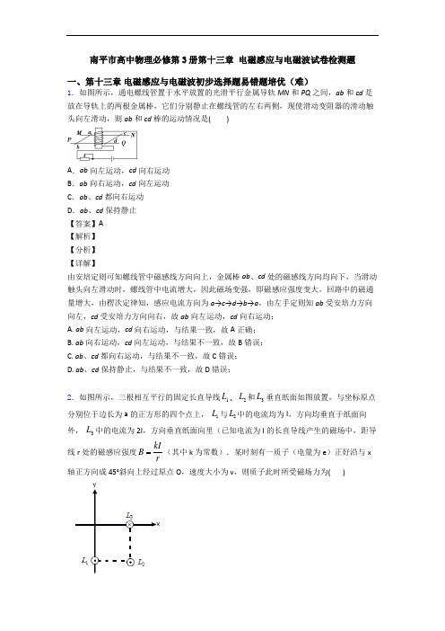
南平市高中物理必修第3册第十三章电磁感应与电磁波试卷检测题一、第十三章电磁感应与电磁波初步选择题易错题培优(难)1.如图所示,通电螺线管置于水平放置的光滑平行金属导轨MN和PQ之间,ab和cd是放在导轨上的两根金属棒,它们分别静止在螺线管的左右两侧,现使滑动变阻器的滑动触头向左滑动,则ab和cd棒的运动情况是()A.ab向左运动,cd向右运动B.ab向右运动,cd向左运动C.ab、cd都向右运动D.ab、cd保持静止【答案】A【解析】【分析】【详解】由安培定则可知螺线管中磁感线方向向上,金属棒ab、cd处的磁感线方向均向下,当滑动触头向左滑动时,螺线管中电流增大,因此磁场变强,即磁感应强度变大,回路中的磁通量增大,由楞次定律知,感应电流方向为a→c→d→b→a,由左手定则知ab受安培力方向向左,cd受安培力方向向右,故ab向左运动,cd向右运动;A. ab向左运动,cd向右运动,与结果一致,故A正确;B. ab向右运动,cd向左运动,与结果不一致,故B错误;C. ab、cd都向右运动,与结果不一致,故C错误;D. ab、cd保持静止,与结果不一致,故D错误;2.如图所示,三根相互平行的固定长直导线1L、2L和3L垂直纸面如图放置,与坐标原点分别位于边长为a的正方形的四个点上,1L与2L中的电流均为I,方向均垂直于纸面向外,3L中的电流为2I,方向垂直纸面向里(已知电流为I的长直导线产生的磁场中,距导线r处的磁感应强度kIBr(其中k为常数).某时刻有一质子(电量为e)正好沿与x轴正方向成45°斜向上经过原点O,速度大小为v,则质子此时所受磁场力为( )A.方向垂直纸面向里,大小为23kIveaB .方向垂直纸面向外,大小为32kIveC .方向垂直纸面向里,大小为32kIveD .方向垂直纸面向外,大小为23kIve【答案】B 【解析】 【详解】根据安培定则,作出三根导线分别在O 点的磁场方向,如图:由题意知,L 1在O 点产生的磁感应强度大小为B 1= kI a,L 2在O 点产生的磁感应强度大小为B 2=2a L 3在O 点产生的磁感应强度大小为B 3=2 kIa,先将B 2正交分解,则沿x 轴负方向的分量为B 2x = 2a °= 2kIa,同理沿y 轴负方向的分量为B 2y =2a °= 2kI a ,故x 轴方向的合磁感应强度为B x =B 1+B 2x =3 2kIa,y 轴方向的合磁感应强度为B y =B 3−B 2y =32kI a ,故最终的合磁感应强度的大小为22322x y kI B B B a==,方向为tanα= yxB B =1,则α=45°,如图:故某时刻有一质子(电量为e)正好沿与x轴正方向成45°斜向上经过原点O,由左手定则可知,洛伦兹力的方向为垂直纸面向外,大小为f=eBv=322kIvea,故B正确; 故选B.【点睛】磁感应强度为矢量,合成时要用平行四边形定则,因此要正确根据安培定则判断导线周围磁场方向是解题的前提.3.取两个完全相同的长导线,用其中一根绕成如图(a)所示的螺线管,当该螺线管中通以电流强度为I的电流时,测得螺线管内中部的磁感应强度大小为B,若将另一根长导线对折后绕成如图(b)所示的螺线管,并通以电流强度也为I的电流时,则在螺线管内中部的磁感应强度大小为()A.0 B.0.5B C.B D.2 B【答案】A【解析】试题分析:乙为双绕线圈,两股导线产生的磁场相互抵消,管内磁感应强度为零,故A正确.考点:磁场的叠加名师点睛:本题比较简单,考查了通电螺线管周围的磁场,弄清两图中电流以及导线的绕法的异同即可正确解答本题.4.如图所示为六根与水平面平行的导线的横截面示意图,导线分布在正六边形的六个角,导线所通电流方向已在图中标出。
电动力学四二(电磁波在介质界面上的反射和折射)
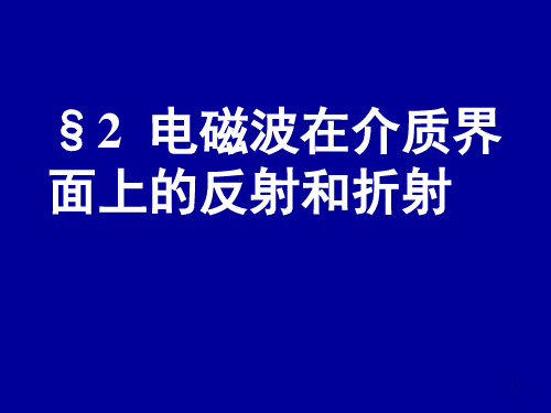
考虑 E’’垂直入射面情况(E’’=Ey’’),
H ''z
2 2
k '' x k ''
E '' y
E''
2 sin 2 n21
H '' x
2 2
k ''z k ''
E '' y
iE''
2 2
sin2
n221 1
Hz’’与E”同相,但Hx’’与E” 有90相位差。
26
折射波平均能流密度
19
菲涅尔公式同时也给出入射波、反射波和 折射波的相位关系。在 E入射面情形, 当2> 1时>’’,因此E’/E为负数, 即反射波电场与入射波电场反相,这现象 称为反射过程中的半波损失。
上面的推导结果与光学实验事 实完全符合,进一步验证了光 的电磁理论的正确性。
20
3.全反射
根据
sin sin ''
30
Байду номын сангаас
振幅关系菲涅耳公式由于对每一波矢k有两个独立的偏振波它们在边界上的行为不同所以需要分别讨论e垂直coscoscoscoscose入射面边值关系式为sinsincoscoscoscossincoscoscoscos并利用折射定律得21sinsin16边值关系式为coscoscos17并利用折射定律得tgtgcossinsincossinsin18上述公式称为菲涅耳公式表示反射波折射波与入射波场强的比值
k k ' , k ''
v1
v2
10
把波矢及它们的分
量值代入它们之间 ' ,
布拉格方程

Reference Documentation
参考文献 [1] 姜贵君,姜贵平,李建华. X射线衍射分析及其在微纤丝 角测定中的应用 [J]. 安徽农业科学, 2010, 38(2): 50-52. [2] 吴绍情. 关于布拉格方程的导出方法 [J]. 云南师范大学 学报(自然科学版), 1985, (4): 78-82. [3] 严燕来. 关于晶体衍射的劳厄方程和布拉格反射公式 的关系_兼与张若森老师商榷 [J]. 大学物理, 1991, 07(5): 15, 23-25. [4] 袁玉珍,邓尚民. 布拉格方程在高聚物结构研究中的应 用[J]. 工科物理, 1998, 08(3): 34-36. [5] 余焜. 广义布拉格方程及其应用 [J]. 理化检验(物理分 册), 2003, 39(4): 27-31. [6] 胡建民,王蕊,王春婷,等. 晶体X射线衍射模型和布拉格 方程的一般推导 [J]. 大学物理, 2015, 34(3): 3-4.
Derivation of Bragg′s equation
特定情况下的多 光束晶面反射模 型
如图 1 所示. 由图 1 可见, 两平行光与晶面交点 A 和 B 的连线垂直于晶面, 反射光的光程差为 CB + BD = 2dsin θ,则可得布拉格方 程 2dsin θ =nλ. 一般情况 下,由于晶体结构的不同, AB 连线不一定垂直于晶面, 所以上述推导过程不具普遍 性.
What is Bragg′s equation?
广义布拉格方程记作2dsinθ=nλ,n 称为晶面周期,θ为入射束与反射 面的夹角 。如果用d表示晶面 距,A′和B′表示晶面方向的晶体 尺寸,C′表示晶面法线方向的晶体 尺寸,。广义布拉格方程不受晶体 尺寸限制,可以在正空间中描述微 晶体衍射的角发散,薄晶体的衍射, 多晶体衍射的积分强度等问题。
2024届北京市高三上学期考前适应性训练物理高频考点试题 (2)
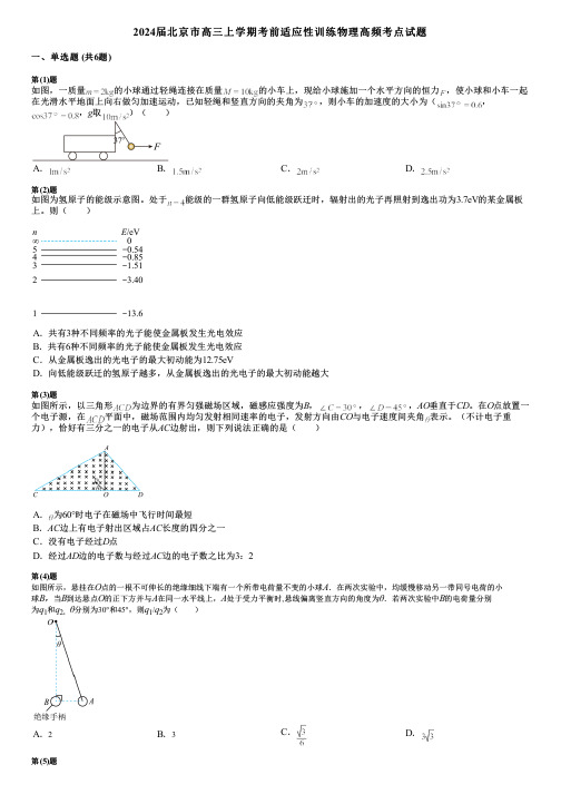
2024届北京市高三上学期考前适应性训练物理高频考点试题一、单选题 (共6题)第(1)题如图,一质量的小球通过轻绳连接在质量的小车上,现给小球施加一个水平方向的恒力,使小球和小车一起在光滑水平地面上向右做匀加速运动,已知轻绳和竖直方向的夹角为,则小车的加速度的大小为(,,g取)( )A.B.C.D.第(2)题如图为氢原子的能级示意图。
处于能级的一群氢原子向低能级跃迁时,辐射出的光子再照射到逸出功为3.7eV的某金属板上。
则( )A.共有3种不同频率的光子能使金属板发生光电效应B.共有6种不同频率的光子能使金属板发生光电效应C.从金属板逸出的光电子的最大初动能为12.75eVD.向低能级跃迁的氢原子越多,从金属板逸出的光电子的最大初动能越大第(3)题如图所示,以三角形为边界的有界匀强磁场区域,磁感应强度为B,,,AO垂直于CD。
在O点放置一个电子源,在平面中,磁场范围内均匀发射相同速率的电子,发射方向由CO与电子速度间夹角表示。
(不计电子重力),恰好有三分之一的电子从AC边射出,则下列说法正确的是( )A.为60°时电子在磁场中飞行时间最短B.AC边上有电子射出区域占AC长度的四分之一C.没有电子经过D点D.经过AD边的电子数与经过AC边的电子数之比为3:2第(4)题如图所示,悬挂在O点的一根不可伸长的绝缘细线下端有一个所带电荷量不变的小球A.在两次实验中,均缓慢移动另一带同号电荷的小球B,当B到达悬点O的正下方并与A在同一水平线上,A处于受力平衡时,悬线偏离竖直方向的角度为θ.若两次实验中B的电荷量分别为q1和q2,θ分别为30°和45°,则q1/q2为() A.2B.3C.D.第(5)题水果的碰伤阈值是指水果在不碰伤的情况下能够从静止竖直跌落的最大高度。
已知导致苹果碰伤所需的平均作用力约为苹果自身重力的3倍。
某学习小组在探究苹果的碰伤阈值实验中,发现苹果从静止竖直跌落,在接触某材料后0.1s减速至0,苹果刚好碰伤,重力加速度g取10m/s2,不计空气阻力,下列说法正确的是( )A.苹果刚接触此材料时的速率约为3m/sB.苹果在此材料的碰伤阈值约为20cmC.苹果在此材料的碰伤阈值与苹果质量成正比D.苹果从静止竖直跌落到减速为0的过程中平均速度为0第(6)题如图所示,A、B为地球的两个轨道共面的人造卫星,运行方向相同,A为地球同步卫星,A、B两卫星的轨道半径的比值为k,地球自转周期为T0。
【市级联考】河南省郑州市2024年高三第二次质量预测理综高效提分物理试题(基础必刷)
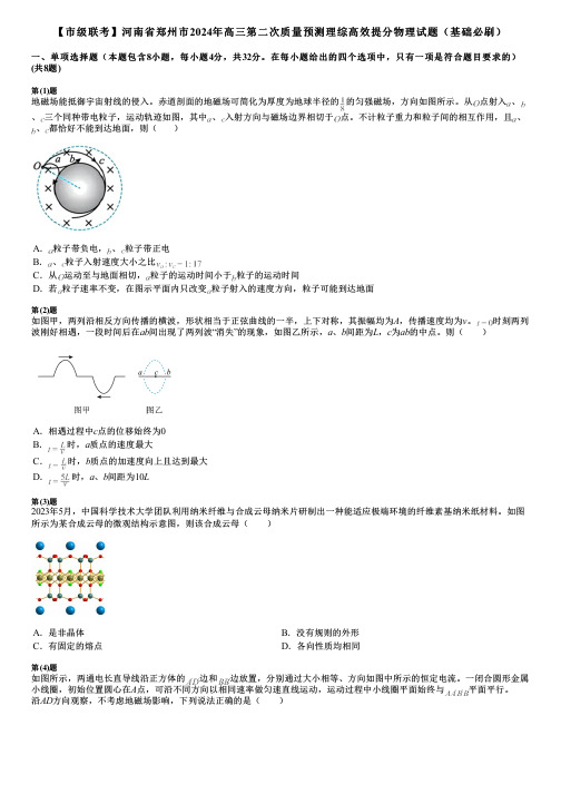
【市级联考】河南省郑州市2024年高三第二次质量预测理综高效提分物理试题(基础必刷)一、单项选择题(本题包含8小题,每小题4分,共32分。
在每小题给出的四个选项中,只有一项是符合题目要求的)(共8题)第(1)题地磁场能抵御宇宙射线的侵入。
赤道剖面的地磁场可简化为厚度为地球半径的的匀强磁场,方向如图所示。
从点射入、、三个同种带电粒子,运动轨迹如图,其中、入射方向与磁场边界相切于点。
不计粒子重力和粒子间的相互作用,且、、都恰好不能到达地面,则()A.粒子带负电,、粒子带正电B.、粒子入射速度大小之比C.从运动至与地面相切,粒子的运动时间小于粒子的运动时间D.若粒子速率不变,在图示平面内只改变粒子射入的速度方向,粒子可能到达地面第(2)题如图甲,两列沿相反方向传播的横波,形状相当于正弦曲线的一半,上下对称,其振幅均为A,传播速度均为v。
时刻两列波刚好相遇,一段时间后在ab间出现了两列波“消失”的现象,如图乙所示,a、b间距为L,c为ab的中点。
则( )A.相遇过程中c点的位移始终为0B.时,a质点的速度最大C.时,b质点的加速度向上且达到最大D.时,a、b间距为10L第(3)题2023年5月,中国科学技术大学团队利用纳米纤维与合成云母纳米片研制出一种能适应极端环境的纤维素基纳米纸材料。
如图所示为某合成云母的微观结构示意图,则该合成云母( )A.是非晶体B.没有规则的外形C.有固定的熔点D.各向性质均相同第(4)题如图所示,两通电长直导线沿正方体的边和边放置,分别通过大小相等、方向如图中所示的恒定电流。
一闭合圆形金属小线圈,初始位置圆心在A点,可沿不同方向以相同速率做匀速直线运动,运动过程中小线圈平面始终与平面平行。
沿AD方向观察,不考虑地磁场影响,下列说法正确的是( )A.C和D两点的磁感应强度相同B.C点的磁感应强度方向由D点指向C点C.小线圈由A点向点移动时能产生顺时针方向的感应电流D.小线圈由A点向D点移动时能产生逆时针方向的感应电流第(5)题如图所示,质量均为m的n(n>3)个相同匀质圆柱体依次搁置在倾角为30°的光滑斜面上,斜面底端有一竖直光滑挡板挡住使圆柱体均处于静止状态.则下列说法中正确的是( )A.挡板对圆柱体1的弹力大小为B.圆柱体1对斜面的压力大小为C.圆柱体2对圆柱体1的压力大小为D.若将挡板绕下端点缓慢逆时针转动60°,则转动过程中斜面对每个圆柱体的支持力均减小第(6)题重型气垫船有强悍的运力,主要用于投送登陆部队。
2023届山东省齐鲁名校大联考高三下学期第三次学业质量检测物理核心考点试题(基础必刷)
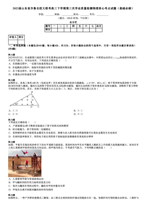
2023届山东省齐鲁名校大联考高三下学期第三次学业质量检测物理核心考点试题(基础必刷)学校:_______ 班级:__________姓名:_______ 考号:__________(满分:100分时间:75分钟)总分栏题号一二三四五六七总分得分评卷人得分一、单项选择题(本题包含8小题,每小题4分,共32分。
在每小题给出的四个选项中,只有一项是符合题目要求的)(共8题)第(1)题2023年8月3日,在成都第31届世界大学生夏季运动会田径项目男子三级跳远决赛中,中国某运动员以的成绩夺得冠军。
不计空气阻力,对该运动员,下列说法正确的是( )A.在助跑过程中,一定做匀加速直线运动B.在起跳的过程中,地面对其做的功等于其机械能的增加量C.在下落过程中,处于失重状态D.在最高点时的速度为零第(2)题如图所示,直角三角形ABC内(包括边界)存在垂直纸面向里的匀强磁场,∠A=30°,BO⊥AC,两个带异种电荷的粒子分别沿OB方向射入磁场,偏向左边的粒子恰好没有从AB边射出磁场,偏向右边的粒子恰好垂直BC边射出磁场,忽略粒子重力和粒子间的相互作用。
若正、负粒子的速度大小之比为1∶3,则正、负粒子的比荷之比为( )A.1∶3B.3∶1C.2∶9D.9∶2第(3)题下列说法正确的是( )A.卢瑟福通过α粒子散射实验提出了原子的核式结构模型B.结合能越大,原子核结构一定越稳定C.某种频率的光不能使某金属发生光电效应,则增大此入射光的光照强度就可以使此金属发生光电效应D.在相同速率情况下,利用电子流比利用质子流制造的显微镜将有更高的分辨率第(4)题如图,平板车在拖拉机的牵引下沿水平道路匀速前进。
某段时间内甲在水平蹦床上跳跃且上升的最大高度越来越大,而坐在车上的乙观察到甲始终沿竖直方向运动。
将甲视为质点,不考虑空气阻力,下列判断正确的是( )A.乙观察到甲做匀变速曲线运动B.甲与蹦床间的作用力始终沿竖直方向C.每次与蹦床作用的过程中,蹦床对甲的冲量均为零D.甲每次从离开到落回蹦床的时间均相同第(5)题如图所示,一种户外野炊便携式三脚架,由三根完全相同的轻杆通过铰链组合在一起,每根杆均可绕铰链自由转动。
