Multicasting in Overlays with Network Layer Support #355
重叠共识名词解释

重叠共识名词解释
重叠共识 (Overlapping Consensus) 是一种分布式系统中的共识算法,旨在解决分布式系统中节点之间的信任问题,确保分布式系统中的数据一致性。
重叠共识算法在多个节点之间进行共识,这些节点之间需要完成某种形式的同步,以便它们能够共同确定区块链的状态。
在重叠共识算法中,节点之间的同步是渐进的,即节点首先发送请求给其他节点,并在收到其他节点的响应后更新自己的状态。
节点之间的同步过程是异步的,这意味着节点可以在不同的时间发送请求和接收响应,而且节点之间的通信是安全的,不需要信任其他节点。
重叠共识算法的主要优点是在不建立信任关系的情况下实现分布式系统中的数据一致性。
这意味着可以在多个节点之间共享数据,而不需要担心节点之间的信任问题。
重叠共识算法还可以提高分布式系统的性能和可扩展性,因为它们允许多个节点同时处理交易并确定区块链的状态。
重叠共识算法的示例包括 PoS(权益共识) 和 DPoS(代议制权益共识) 算法。
其中,PoS 算法中节点通过赢得选举或拥有足够的代币数量来获得对区块链的共识控制权;而 DPoS 算法中,节点可以通过提交提案并获得足够的支持来获得对区块链的共识控制权。
这两种算法都具有优点和缺点,可以根据具体情况选择。
CiteSpace中文手册
如果你愿意引用本手册,格式如下: 李杰. CiteSpace 中文版指南. 网址[EB/OL][YYYY-MM-DD].2015 年
CiteSpace 中文版指南
李杰
首都经济贸易大学 安全与环境工程学院
个人主页:/u/jerrycueb E-mail:lijie_jerry@
2 中文 CNKI 数据的分析实践...................................................................................................... 15 2.1 CiteSpace 数据转换功能区 ................................................................................................ 15 2.2 CNKI 数据分析 .................................................................................................................... 16
CJJ 169-2011 城镇道路路面设计规范

3 基本规定................................................................................................................................ 8
3.1 一般规定 ......................................................................................................................................... 8 3.2 设计要素 ......................................................................................................................................... 8
2.1 术语 ................................................................................................................................................. 2 2.2 符号 ................................................................................................................................................. 3
6 水泥混凝土路面.................................................................................................................. 34
overlay网络技术之VxLAN详解
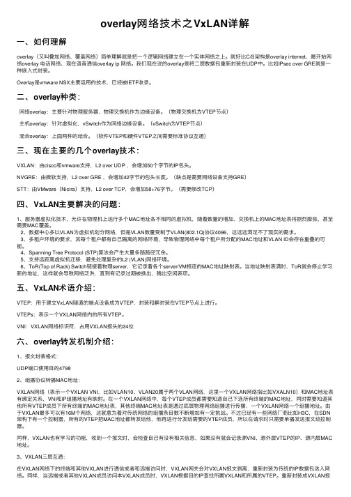
overlay⽹络技术之VxLAN详解⼀、如何理解overlay(⼜叫叠加⽹络、覆盖⽹络)简单理解就是把⼀个逻辑⽹络建⽴在⼀个实体⽹络之上。
就好⽐C/S架构是overlay internet、最开始⽹络overlay 电话⽹络、现在语⾳通信overlay ip ⽹络。
我们现在说的overlay是将⼆层数据包重新封装在UDP中。
⽐如IPsec over GRE就是⼀种嵌⼊式封装。
Overlay是vmware NSX主要运⽤的技术,已经被IETF收录。
⼆、overlay种类:⽹络overlay:主要针对物理服务器,物理交换机作为边缘设备。
(物理交换机为VTEP节点)主机overlay:针对虚拟化,vSwitch作为⽹络边缘设备。
(vSwitch为VTEP节点)混合overlay:上⾯两种的结合。
(软件VTEP和硬件VTEP之间需要标准协议互通)三、现在主要的⼏个overlay技术:VXLAN:由cisco和vmware⽀持,L2 over UDP ,会增加50个字节的IP包头。
NVGRE:由微软⽀持,L2 over GRE ,会增加42字节的包头长度。
(缺点是需要⽹络设备⽀持GRE)STT:由VMware(Nicira)⽀持,L2 over TCP,会增加58+76字节。
(需要修改TCP)四、VxLAN主要解决的问题:1、服务器虚拟化技术,允许在物理机上运⾏多个MAC地址各不相同的虚拟机,随着数量的增加,交换机上的MAC地址表将剧烈膨胀,甚⾄需要MAC覆盖。
2、数据中⼼多以VLAN为虚拟机划分⽹络,但是VLAN数量受制于VLAN(802.1Q)协议4096,这远远满⾜不了现实的需求。
3、多租户环境的要求,其每个租户都有⾃⼰隔离的⽹络环境,导致物理⽹络中每个租户所分配的MAC地址和VLAN ID会存在重叠的可能。
4、Spanning Tree Protocol (STP)算法会产⽣⼤量多路路径冗余。
5、⽀持远距离虚拟机迁移,避免处理复杂的L2 (VLAN)⽹络环境。
11.如何使用网络叠加功能(Network Overlays)

如何使用CiteSpace进行文献的Overlay分析
李杰
首都经济贸易大学安全与环境工程学院
个人主页:/u/jerrycueb
1. 对数据整体网络的初步分析
此处的数据采用软件自带的“terrorism”案例数据。
文献Overlay分析的关键点是在时间维度上的图层叠加,首先选择的时间切片为1996-2003,得到的恐怖主义研究的文献共被引网络如右图。
得到了N=309,E=1107的网络。
2.构建新图层
图层1: 1996-2000年的文献yer
1
2
3
4
2.构建新图层network12
yer 图层2: 2001-2003年的文献1234
3. Overlay分析
12
选择时间切片1996-2003重新制作恐怖主义研究的整个
数据时间段内的文献共被引网络,并调整颜色使其颜
色变浅。
3. Overlay 分析6534
3. Overlay分析结果
3. 时间维度的网络分析。
华为MA5616

约定
符号约定
在本文中可能出现下列标志,它们所代表的含义如下。
符号
说明
以本标志开始的文本表示有高度潜在危险,如果不能避 免,会导致人员死亡或严重伤害。
以本标志开始的文本表示有中度或低度潜在危险,如果 不能避免,可能导致人员轻微或中等伤害。
以本标志开始的文本表示有潜在风险,如果忽视这些文 本,可能导致设备损坏、数据丢失、设备性能降低或不 可预知的结果。
由于产品版本升级或其他原因,本文档内容会不定期进行更新。除非另有约定,本文档仅作为使用指导,本文 档中的所有陈述、信息和建议不构成任何明示或暗示的担保。
华为技术有限公司
地址:
深圳市龙岗区坂田华为总部办公楼 邮编:518129
网址:
客户服务邮箱: support@
意义 表示在键盘上同时按下几个键。如“Ctrl+Alt+A”表示同时 按下“Ctrl”、“Alt”、“A”这三个键。 表示先按第一键,释放,再按第二键。如“Alt,F”表示先 按“Alt”键,释放后再按“F”键。
意义 快速按下并释放鼠标的一个按钮。 连续两次快速按下并释放鼠标的一个按钮。 按住鼠标的一个按钮不放,移动鼠标。
表示从两个或多个选项中选取多个或者不选。
图形界面元素引用约定
格式 “”
>
意义
带双引号“”的格式表示各类界面控件名称和数据表,如 单击“确定”。
多级菜单用“>”隔开。如选择“文件 > 新建 > 文件夹”, 表示选择“文件”菜单下的“新建”子菜单下的“文件 夹”菜单项。
键盘操作约定
格式 加“”的字符
意义
客户服务电话: 0755-28560000 4008302118
云数据中心网络技术之neutronoverlay的实现

Overlay网络的实现方式
• Overlay网络是一种将物理网络划分为多个逻辑网络的技
01
术,通过在虚拟机上添加一层逻辑网络来实现。
02
• Overlay网络通过隧道技术(如GRE、VXLAN)将虚拟
机的流量封装在物理网络的隧道中传输。
• Overlay网络能够实现跨物理主机的虚拟机之间的通信,
GRE和GENEVE协议的实现
GRE
• GRE(Generic Routing Encapsulation)是一种用于封装任意类型的数据包,并将其封装在另一个IP数据包中的协 议。
GENEVE
• GENEVE(Generic Network Virtualization Encapsulation)是一种类似于VXLAN的overlay网络技术,同样用于实 现跨物理网络的逻辑子网互联。
02
Neutron overlay架构概述
Neutron概述
• Neutron是OpenStack的核心组件之一,
1
负责云数据中心的虚拟网络管理。
• Neutron具有高度可扩展性和灵活性,通
2
过插件或模块的方式支持多种网络技术。
• Neutron的目标是提供一种云操作系统,
3
用于构建和管理不同需求的虚拟网络。
结果展示
• Neutron overlay实现了租户网络的隔离、通信以及IP地址的自动分配,提高了云 服务提供商的网络管理效率。
Neutron overl球知名的互联网公司,拥有海量用户和业务需求。
02 03
实践描述
• 在某大型互联网公司中,Neutron overlay被用于连接数以千计的虚拟机 实例和各种业务网络。该公司还使用了 Neutron的安全组功能,实现了对虚 拟机实例的安全控制
3GPP TS 36.331 V13.2.0 (2016-06)

3GPP TS 36.331 V13.2.0 (2016-06)Technical Specification3rd Generation Partnership Project;Technical Specification Group Radio Access Network;Evolved Universal Terrestrial Radio Access (E-UTRA);Radio Resource Control (RRC);Protocol specification(Release 13)The present document has been developed within the 3rd Generation Partnership Project (3GPP TM) and may be further elaborated for the purposes of 3GPP. The present document has not been subject to any approval process by the 3GPP Organizational Partners and shall not be implemented.This Specification is provided for future development work within 3GPP only. The Organizational Partners accept no liability for any use of this Specification. Specifications and reports for implementation of the 3GPP TM system should be obtained via the 3GPP Organizational Partners' Publications Offices.KeywordsUMTS, radio3GPPPostal address3GPP support office address650 Route des Lucioles - Sophia AntipolisValbonne - FRANCETel.: +33 4 92 94 42 00 Fax: +33 4 93 65 47 16InternetCopyright NotificationNo part may be reproduced except as authorized by written permission.The copyright and the foregoing restriction extend to reproduction in all media.© 2016, 3GPP Organizational Partners (ARIB, ATIS, CCSA, ETSI, TSDSI, TTA, TTC).All rights reserved.UMTS™ is a Trade Mark of ETSI registered for the benefit of its members3GPP™ is a Trade Mark of ETSI registered for the benefit of its Members and of the 3GPP Organizational PartnersLTE™ is a Trade Mark of ETSI currently being registered for the benefit of its Members and of the 3GPP Organizational Partners GSM® and the GSM logo are registered and owned by the GSM AssociationBluetooth® is a Trade Mark of the Bluetooth SIG registered for the benefit of its membersContentsForeword (18)1Scope (19)2References (19)3Definitions, symbols and abbreviations (22)3.1Definitions (22)3.2Abbreviations (24)4General (27)4.1Introduction (27)4.2Architecture (28)4.2.1UE states and state transitions including inter RAT (28)4.2.2Signalling radio bearers (29)4.3Services (30)4.3.1Services provided to upper layers (30)4.3.2Services expected from lower layers (30)4.4Functions (30)5Procedures (32)5.1General (32)5.1.1Introduction (32)5.1.2General requirements (32)5.2System information (33)5.2.1Introduction (33)5.2.1.1General (33)5.2.1.2Scheduling (34)5.2.1.2a Scheduling for NB-IoT (34)5.2.1.3System information validity and notification of changes (35)5.2.1.4Indication of ETWS notification (36)5.2.1.5Indication of CMAS notification (37)5.2.1.6Notification of EAB parameters change (37)5.2.1.7Access Barring parameters change in NB-IoT (37)5.2.2System information acquisition (38)5.2.2.1General (38)5.2.2.2Initiation (38)5.2.2.3System information required by the UE (38)5.2.2.4System information acquisition by the UE (39)5.2.2.5Essential system information missing (42)5.2.2.6Actions upon reception of the MasterInformationBlock message (42)5.2.2.7Actions upon reception of the SystemInformationBlockType1 message (42)5.2.2.8Actions upon reception of SystemInformation messages (44)5.2.2.9Actions upon reception of SystemInformationBlockType2 (44)5.2.2.10Actions upon reception of SystemInformationBlockType3 (45)5.2.2.11Actions upon reception of SystemInformationBlockType4 (45)5.2.2.12Actions upon reception of SystemInformationBlockType5 (45)5.2.2.13Actions upon reception of SystemInformationBlockType6 (45)5.2.2.14Actions upon reception of SystemInformationBlockType7 (45)5.2.2.15Actions upon reception of SystemInformationBlockType8 (45)5.2.2.16Actions upon reception of SystemInformationBlockType9 (46)5.2.2.17Actions upon reception of SystemInformationBlockType10 (46)5.2.2.18Actions upon reception of SystemInformationBlockType11 (46)5.2.2.19Actions upon reception of SystemInformationBlockType12 (47)5.2.2.20Actions upon reception of SystemInformationBlockType13 (48)5.2.2.21Actions upon reception of SystemInformationBlockType14 (48)5.2.2.22Actions upon reception of SystemInformationBlockType15 (48)5.2.2.23Actions upon reception of SystemInformationBlockType16 (48)5.2.2.24Actions upon reception of SystemInformationBlockType17 (48)5.2.2.25Actions upon reception of SystemInformationBlockType18 (48)5.2.2.26Actions upon reception of SystemInformationBlockType19 (49)5.2.3Acquisition of an SI message (49)5.2.3a Acquisition of an SI message by BL UE or UE in CE or a NB-IoT UE (50)5.3Connection control (50)5.3.1Introduction (50)5.3.1.1RRC connection control (50)5.3.1.2Security (52)5.3.1.2a RN security (53)5.3.1.3Connected mode mobility (53)5.3.1.4Connection control in NB-IoT (54)5.3.2Paging (55)5.3.2.1General (55)5.3.2.2Initiation (55)5.3.2.3Reception of the Paging message by the UE (55)5.3.3RRC connection establishment (56)5.3.3.1General (56)5.3.3.1a Conditions for establishing RRC Connection for sidelink communication/ discovery (58)5.3.3.2Initiation (59)5.3.3.3Actions related to transmission of RRCConnectionRequest message (63)5.3.3.3a Actions related to transmission of RRCConnectionResumeRequest message (64)5.3.3.4Reception of the RRCConnectionSetup by the UE (64)5.3.3.4a Reception of the RRCConnectionResume by the UE (66)5.3.3.5Cell re-selection while T300, T302, T303, T305, T306, or T308 is running (68)5.3.3.6T300 expiry (68)5.3.3.7T302, T303, T305, T306, or T308 expiry or stop (69)5.3.3.8Reception of the RRCConnectionReject by the UE (70)5.3.3.9Abortion of RRC connection establishment (71)5.3.3.10Handling of SSAC related parameters (71)5.3.3.11Access barring check (72)5.3.3.12EAB check (73)5.3.3.13Access barring check for ACDC (73)5.3.3.14Access Barring check for NB-IoT (74)5.3.4Initial security activation (75)5.3.4.1General (75)5.3.4.2Initiation (76)5.3.4.3Reception of the SecurityModeCommand by the UE (76)5.3.5RRC connection reconfiguration (77)5.3.5.1General (77)5.3.5.2Initiation (77)5.3.5.3Reception of an RRCConnectionReconfiguration not including the mobilityControlInfo by theUE (77)5.3.5.4Reception of an RRCConnectionReconfiguration including the mobilityControlInfo by the UE(handover) (79)5.3.5.5Reconfiguration failure (83)5.3.5.6T304 expiry (handover failure) (83)5.3.5.7Void (84)5.3.5.7a T307 expiry (SCG change failure) (84)5.3.5.8Radio Configuration involving full configuration option (84)5.3.6Counter check (86)5.3.6.1General (86)5.3.6.2Initiation (86)5.3.6.3Reception of the CounterCheck message by the UE (86)5.3.7RRC connection re-establishment (87)5.3.7.1General (87)5.3.7.2Initiation (87)5.3.7.3Actions following cell selection while T311 is running (88)5.3.7.4Actions related to transmission of RRCConnectionReestablishmentRequest message (89)5.3.7.5Reception of the RRCConnectionReestablishment by the UE (89)5.3.7.6T311 expiry (91)5.3.7.7T301 expiry or selected cell no longer suitable (91)5.3.7.8Reception of RRCConnectionReestablishmentReject by the UE (91)5.3.8RRC connection release (92)5.3.8.1General (92)5.3.8.2Initiation (92)5.3.8.3Reception of the RRCConnectionRelease by the UE (92)5.3.8.4T320 expiry (93)5.3.9RRC connection release requested by upper layers (93)5.3.9.1General (93)5.3.9.2Initiation (93)5.3.10Radio resource configuration (93)5.3.10.0General (93)5.3.10.1SRB addition/ modification (94)5.3.10.2DRB release (95)5.3.10.3DRB addition/ modification (95)5.3.10.3a1DC specific DRB addition or reconfiguration (96)5.3.10.3a2LWA specific DRB addition or reconfiguration (98)5.3.10.3a3LWIP specific DRB addition or reconfiguration (98)5.3.10.3a SCell release (99)5.3.10.3b SCell addition/ modification (99)5.3.10.3c PSCell addition or modification (99)5.3.10.4MAC main reconfiguration (99)5.3.10.5Semi-persistent scheduling reconfiguration (100)5.3.10.6Physical channel reconfiguration (100)5.3.10.7Radio Link Failure Timers and Constants reconfiguration (101)5.3.10.8Time domain measurement resource restriction for serving cell (101)5.3.10.9Other configuration (102)5.3.10.10SCG reconfiguration (103)5.3.10.11SCG dedicated resource configuration (104)5.3.10.12Reconfiguration SCG or split DRB by drb-ToAddModList (105)5.3.10.13Neighbour cell information reconfiguration (105)5.3.10.14Void (105)5.3.10.15Sidelink dedicated configuration (105)5.3.10.16T370 expiry (106)5.3.11Radio link failure related actions (107)5.3.11.1Detection of physical layer problems in RRC_CONNECTED (107)5.3.11.2Recovery of physical layer problems (107)5.3.11.3Detection of radio link failure (107)5.3.12UE actions upon leaving RRC_CONNECTED (109)5.3.13UE actions upon PUCCH/ SRS release request (110)5.3.14Proximity indication (110)5.3.14.1General (110)5.3.14.2Initiation (111)5.3.14.3Actions related to transmission of ProximityIndication message (111)5.3.15Void (111)5.4Inter-RAT mobility (111)5.4.1Introduction (111)5.4.2Handover to E-UTRA (112)5.4.2.1General (112)5.4.2.2Initiation (112)5.4.2.3Reception of the RRCConnectionReconfiguration by the UE (112)5.4.2.4Reconfiguration failure (114)5.4.2.5T304 expiry (handover to E-UTRA failure) (114)5.4.3Mobility from E-UTRA (114)5.4.3.1General (114)5.4.3.2Initiation (115)5.4.3.3Reception of the MobilityFromEUTRACommand by the UE (115)5.4.3.4Successful completion of the mobility from E-UTRA (116)5.4.3.5Mobility from E-UTRA failure (117)5.4.4Handover from E-UTRA preparation request (CDMA2000) (117)5.4.4.1General (117)5.4.4.2Initiation (118)5.4.4.3Reception of the HandoverFromEUTRAPreparationRequest by the UE (118)5.4.5UL handover preparation transfer (CDMA2000) (118)5.4.5.1General (118)5.4.5.2Initiation (118)5.4.5.3Actions related to transmission of the ULHandoverPreparationTransfer message (119)5.4.5.4Failure to deliver the ULHandoverPreparationTransfer message (119)5.4.6Inter-RAT cell change order to E-UTRAN (119)5.4.6.1General (119)5.4.6.2Initiation (119)5.4.6.3UE fails to complete an inter-RAT cell change order (119)5.5Measurements (120)5.5.1Introduction (120)5.5.2Measurement configuration (121)5.5.2.1General (121)5.5.2.2Measurement identity removal (122)5.5.2.2a Measurement identity autonomous removal (122)5.5.2.3Measurement identity addition/ modification (123)5.5.2.4Measurement object removal (124)5.5.2.5Measurement object addition/ modification (124)5.5.2.6Reporting configuration removal (126)5.5.2.7Reporting configuration addition/ modification (127)5.5.2.8Quantity configuration (127)5.5.2.9Measurement gap configuration (127)5.5.2.10Discovery signals measurement timing configuration (128)5.5.2.11RSSI measurement timing configuration (128)5.5.3Performing measurements (128)5.5.3.1General (128)5.5.3.2Layer 3 filtering (131)5.5.4Measurement report triggering (131)5.5.4.1General (131)5.5.4.2Event A1 (Serving becomes better than threshold) (135)5.5.4.3Event A2 (Serving becomes worse than threshold) (136)5.5.4.4Event A3 (Neighbour becomes offset better than PCell/ PSCell) (136)5.5.4.5Event A4 (Neighbour becomes better than threshold) (137)5.5.4.6Event A5 (PCell/ PSCell becomes worse than threshold1 and neighbour becomes better thanthreshold2) (138)5.5.4.6a Event A6 (Neighbour becomes offset better than SCell) (139)5.5.4.7Event B1 (Inter RAT neighbour becomes better than threshold) (139)5.5.4.8Event B2 (PCell becomes worse than threshold1 and inter RAT neighbour becomes better thanthreshold2) (140)5.5.4.9Event C1 (CSI-RS resource becomes better than threshold) (141)5.5.4.10Event C2 (CSI-RS resource becomes offset better than reference CSI-RS resource) (141)5.5.4.11Event W1 (WLAN becomes better than a threshold) (142)5.5.4.12Event W2 (All WLAN inside WLAN mobility set becomes worse than threshold1 and a WLANoutside WLAN mobility set becomes better than threshold2) (142)5.5.4.13Event W3 (All WLAN inside WLAN mobility set becomes worse than a threshold) (143)5.5.5Measurement reporting (144)5.5.6Measurement related actions (148)5.5.6.1Actions upon handover and re-establishment (148)5.5.6.2Speed dependant scaling of measurement related parameters (149)5.5.7Inter-frequency RSTD measurement indication (149)5.5.7.1General (149)5.5.7.2Initiation (150)5.5.7.3Actions related to transmission of InterFreqRSTDMeasurementIndication message (150)5.6Other (150)5.6.0General (150)5.6.1DL information transfer (151)5.6.1.1General (151)5.6.1.2Initiation (151)5.6.1.3Reception of the DLInformationTransfer by the UE (151)5.6.2UL information transfer (151)5.6.2.1General (151)5.6.2.2Initiation (151)5.6.2.3Actions related to transmission of ULInformationTransfer message (152)5.6.2.4Failure to deliver ULInformationTransfer message (152)5.6.3UE capability transfer (152)5.6.3.1General (152)5.6.3.2Initiation (153)5.6.3.3Reception of the UECapabilityEnquiry by the UE (153)5.6.4CSFB to 1x Parameter transfer (157)5.6.4.1General (157)5.6.4.2Initiation (157)5.6.4.3Actions related to transmission of CSFBParametersRequestCDMA2000 message (157)5.6.4.4Reception of the CSFBParametersResponseCDMA2000 message (157)5.6.5UE Information (158)5.6.5.1General (158)5.6.5.2Initiation (158)5.6.5.3Reception of the UEInformationRequest message (158)5.6.6 Logged Measurement Configuration (159)5.6.6.1General (159)5.6.6.2Initiation (160)5.6.6.3Reception of the LoggedMeasurementConfiguration by the UE (160)5.6.6.4T330 expiry (160)5.6.7 Release of Logged Measurement Configuration (160)5.6.7.1General (160)5.6.7.2Initiation (160)5.6.8 Measurements logging (161)5.6.8.1General (161)5.6.8.2Initiation (161)5.6.9In-device coexistence indication (163)5.6.9.1General (163)5.6.9.2Initiation (164)5.6.9.3Actions related to transmission of InDeviceCoexIndication message (164)5.6.10UE Assistance Information (165)5.6.10.1General (165)5.6.10.2Initiation (166)5.6.10.3Actions related to transmission of UEAssistanceInformation message (166)5.6.11 Mobility history information (166)5.6.11.1General (166)5.6.11.2Initiation (166)5.6.12RAN-assisted WLAN interworking (167)5.6.12.1General (167)5.6.12.2Dedicated WLAN offload configuration (167)5.6.12.3WLAN offload RAN evaluation (167)5.6.12.4T350 expiry or stop (167)5.6.12.5Cell selection/ re-selection while T350 is running (168)5.6.13SCG failure information (168)5.6.13.1General (168)5.6.13.2Initiation (168)5.6.13.3Actions related to transmission of SCGFailureInformation message (168)5.6.14LTE-WLAN Aggregation (169)5.6.14.1Introduction (169)5.6.14.2Reception of LWA configuration (169)5.6.14.3Release of LWA configuration (170)5.6.15WLAN connection management (170)5.6.15.1Introduction (170)5.6.15.2WLAN connection status reporting (170)5.6.15.2.1General (170)5.6.15.2.2Initiation (171)5.6.15.2.3Actions related to transmission of WLANConnectionStatusReport message (171)5.6.15.3T351 Expiry (WLAN connection attempt timeout) (171)5.6.15.4WLAN status monitoring (171)5.6.16RAN controlled LTE-WLAN interworking (172)5.6.16.1General (172)5.6.16.2WLAN traffic steering command (172)5.6.17LTE-WLAN aggregation with IPsec tunnel (173)5.6.17.1General (173)5.7Generic error handling (174)5.7.1General (174)5.7.2ASN.1 violation or encoding error (174)5.7.3Field set to a not comprehended value (174)5.7.4Mandatory field missing (174)5.7.5Not comprehended field (176)5.8MBMS (176)5.8.1Introduction (176)5.8.1.1General (176)5.8.1.2Scheduling (176)5.8.1.3MCCH information validity and notification of changes (176)5.8.2MCCH information acquisition (178)5.8.2.1General (178)5.8.2.2Initiation (178)5.8.2.3MCCH information acquisition by the UE (178)5.8.2.4Actions upon reception of the MBSFNAreaConfiguration message (178)5.8.2.5Actions upon reception of the MBMSCountingRequest message (179)5.8.3MBMS PTM radio bearer configuration (179)5.8.3.1General (179)5.8.3.2Initiation (179)5.8.3.3MRB establishment (179)5.8.3.4MRB release (179)5.8.4MBMS Counting Procedure (179)5.8.4.1General (179)5.8.4.2Initiation (180)5.8.4.3Reception of the MBMSCountingRequest message by the UE (180)5.8.5MBMS interest indication (181)5.8.5.1General (181)5.8.5.2Initiation (181)5.8.5.3Determine MBMS frequencies of interest (182)5.8.5.4Actions related to transmission of MBMSInterestIndication message (183)5.8a SC-PTM (183)5.8a.1Introduction (183)5.8a.1.1General (183)5.8a.1.2SC-MCCH scheduling (183)5.8a.1.3SC-MCCH information validity and notification of changes (183)5.8a.1.4Procedures (184)5.8a.2SC-MCCH information acquisition (184)5.8a.2.1General (184)5.8a.2.2Initiation (184)5.8a.2.3SC-MCCH information acquisition by the UE (184)5.8a.2.4Actions upon reception of the SCPTMConfiguration message (185)5.8a.3SC-PTM radio bearer configuration (185)5.8a.3.1General (185)5.8a.3.2Initiation (185)5.8a.3.3SC-MRB establishment (185)5.8a.3.4SC-MRB release (185)5.9RN procedures (186)5.9.1RN reconfiguration (186)5.9.1.1General (186)5.9.1.2Initiation (186)5.9.1.3Reception of the RNReconfiguration by the RN (186)5.10Sidelink (186)5.10.1Introduction (186)5.10.1a Conditions for sidelink communication operation (187)5.10.2Sidelink UE information (188)5.10.2.1General (188)5.10.2.2Initiation (189)5.10.2.3Actions related to transmission of SidelinkUEInformation message (193)5.10.3Sidelink communication monitoring (195)5.10.6Sidelink discovery announcement (198)5.10.6a Sidelink discovery announcement pool selection (201)5.10.6b Sidelink discovery announcement reference carrier selection (201)5.10.7Sidelink synchronisation information transmission (202)5.10.7.1General (202)5.10.7.2Initiation (203)5.10.7.3Transmission of SLSS (204)5.10.7.4Transmission of MasterInformationBlock-SL message (205)5.10.7.5Void (206)5.10.8Sidelink synchronisation reference (206)5.10.8.1General (206)5.10.8.2Selection and reselection of synchronisation reference UE (SyncRef UE) (206)5.10.9Sidelink common control information (207)5.10.9.1General (207)5.10.9.2Actions related to reception of MasterInformationBlock-SL message (207)5.10.10Sidelink relay UE operation (207)5.10.10.1General (207)5.10.10.2AS-conditions for relay related sidelink communication transmission by sidelink relay UE (207)5.10.10.3AS-conditions for relay PS related sidelink discovery transmission by sidelink relay UE (208)5.10.10.4Sidelink relay UE threshold conditions (208)5.10.11Sidelink remote UE operation (208)5.10.11.1General (208)5.10.11.2AS-conditions for relay related sidelink communication transmission by sidelink remote UE (208)5.10.11.3AS-conditions for relay PS related sidelink discovery transmission by sidelink remote UE (209)5.10.11.4Selection and reselection of sidelink relay UE (209)5.10.11.5Sidelink remote UE threshold conditions (210)6Protocol data units, formats and parameters (tabular & ASN.1) (210)6.1General (210)6.2RRC messages (212)6.2.1General message structure (212)–EUTRA-RRC-Definitions (212)–BCCH-BCH-Message (212)–BCCH-DL-SCH-Message (212)–BCCH-DL-SCH-Message-BR (213)–MCCH-Message (213)–PCCH-Message (213)–DL-CCCH-Message (214)–DL-DCCH-Message (214)–UL-CCCH-Message (214)–UL-DCCH-Message (215)–SC-MCCH-Message (215)6.2.2Message definitions (216)–CounterCheck (216)–CounterCheckResponse (217)–CSFBParametersRequestCDMA2000 (217)–CSFBParametersResponseCDMA2000 (218)–DLInformationTransfer (218)–HandoverFromEUTRAPreparationRequest (CDMA2000) (219)–InDeviceCoexIndication (220)–InterFreqRSTDMeasurementIndication (222)–LoggedMeasurementConfiguration (223)–MasterInformationBlock (225)–MBMSCountingRequest (226)–MBMSCountingResponse (226)–MBMSInterestIndication (227)–MBSFNAreaConfiguration (228)–MeasurementReport (228)–MobilityFromEUTRACommand (229)–Paging (232)–ProximityIndication (233)–RNReconfiguration (234)–RNReconfigurationComplete (234)–RRCConnectionReconfiguration (235)–RRCConnectionReconfigurationComplete (240)–RRCConnectionReestablishment (241)–RRCConnectionReestablishmentComplete (241)–RRCConnectionReestablishmentReject (242)–RRCConnectionReestablishmentRequest (243)–RRCConnectionReject (243)–RRCConnectionRelease (244)–RRCConnectionResume (248)–RRCConnectionResumeComplete (249)–RRCConnectionResumeRequest (250)–RRCConnectionRequest (250)–RRCConnectionSetup (251)–RRCConnectionSetupComplete (252)–SCGFailureInformation (253)–SCPTMConfiguration (254)–SecurityModeCommand (255)–SecurityModeComplete (255)–SecurityModeFailure (256)–SidelinkUEInformation (256)–SystemInformation (258)–SystemInformationBlockType1 (259)–UEAssistanceInformation (264)–UECapabilityEnquiry (265)–UECapabilityInformation (266)–UEInformationRequest (267)–UEInformationResponse (267)–ULHandoverPreparationTransfer (CDMA2000) (273)–ULInformationTransfer (274)–WLANConnectionStatusReport (274)6.3RRC information elements (275)6.3.1System information blocks (275)–SystemInformationBlockType2 (275)–SystemInformationBlockType3 (279)–SystemInformationBlockType4 (282)–SystemInformationBlockType5 (283)–SystemInformationBlockType6 (287)–SystemInformationBlockType7 (289)–SystemInformationBlockType8 (290)–SystemInformationBlockType9 (295)–SystemInformationBlockType10 (295)–SystemInformationBlockType11 (296)–SystemInformationBlockType12 (297)–SystemInformationBlockType13 (297)–SystemInformationBlockType14 (298)–SystemInformationBlockType15 (298)–SystemInformationBlockType16 (299)–SystemInformationBlockType17 (300)–SystemInformationBlockType18 (301)–SystemInformationBlockType19 (301)–SystemInformationBlockType20 (304)6.3.2Radio resource control information elements (304)–AntennaInfo (304)–AntennaInfoUL (306)–CQI-ReportConfig (307)–CQI-ReportPeriodicProcExtId (314)–CrossCarrierSchedulingConfig (314)–CSI-IM-Config (315)–CSI-IM-ConfigId (315)–CSI-RS-Config (317)–CSI-RS-ConfigEMIMO (318)–CSI-RS-ConfigNZP (319)–CSI-RS-ConfigNZPId (320)–CSI-RS-ConfigZP (321)–CSI-RS-ConfigZPId (321)–DMRS-Config (321)–DRB-Identity (322)–EPDCCH-Config (322)–EIMTA-MainConfig (324)–LogicalChannelConfig (325)–LWA-Configuration (326)–LWIP-Configuration (326)–RCLWI-Configuration (327)–MAC-MainConfig (327)–P-C-AndCBSR (332)–PDCCH-ConfigSCell (333)–PDCP-Config (334)–PDSCH-Config (337)–PDSCH-RE-MappingQCL-ConfigId (339)–PHICH-Config (339)–PhysicalConfigDedicated (339)–P-Max (344)–PRACH-Config (344)–PresenceAntennaPort1 (346)–PUCCH-Config (347)–PUSCH-Config (351)–RACH-ConfigCommon (355)–RACH-ConfigDedicated (357)–RadioResourceConfigCommon (358)–RadioResourceConfigDedicated (362)–RLC-Config (367)–RLF-TimersAndConstants (369)–RN-SubframeConfig (370)–SchedulingRequestConfig (371)–SoundingRS-UL-Config (372)–SPS-Config (375)–TDD-Config (376)–TimeAlignmentTimer (377)–TPC-PDCCH-Config (377)–TunnelConfigLWIP (378)–UplinkPowerControl (379)–WLAN-Id-List (382)–WLAN-MobilityConfig (382)6.3.3Security control information elements (382)–NextHopChainingCount (382)–SecurityAlgorithmConfig (383)–ShortMAC-I (383)6.3.4Mobility control information elements (383)–AdditionalSpectrumEmission (383)–ARFCN-ValueCDMA2000 (383)–ARFCN-ValueEUTRA (384)–ARFCN-ValueGERAN (384)–ARFCN-ValueUTRA (384)–BandclassCDMA2000 (384)–BandIndicatorGERAN (385)–CarrierFreqCDMA2000 (385)–CarrierFreqGERAN (385)–CellIndexList (387)–CellReselectionPriority (387)–CellSelectionInfoCE (387)–CellReselectionSubPriority (388)–CSFB-RegistrationParam1XRTT (388)–CellGlobalIdEUTRA (389)–CellGlobalIdUTRA (389)–CellGlobalIdGERAN (390)–CellGlobalIdCDMA2000 (390)–CellSelectionInfoNFreq (391)–CSG-Identity (391)–FreqBandIndicator (391)–MobilityControlInfo (391)–MobilityParametersCDMA2000 (1xRTT) (393)–MobilityStateParameters (394)–MultiBandInfoList (394)–NS-PmaxList (394)–PhysCellId (395)–PhysCellIdRange (395)–PhysCellIdRangeUTRA-FDDList (395)–PhysCellIdCDMA2000 (396)–PhysCellIdGERAN (396)–PhysCellIdUTRA-FDD (396)–PhysCellIdUTRA-TDD (396)–PLMN-Identity (397)–PLMN-IdentityList3 (397)–PreRegistrationInfoHRPD (397)–Q-QualMin (398)–Q-RxLevMin (398)–Q-OffsetRange (398)–Q-OffsetRangeInterRAT (399)–ReselectionThreshold (399)–ReselectionThresholdQ (399)–SCellIndex (399)–ServCellIndex (400)–SpeedStateScaleFactors (400)–SystemInfoListGERAN (400)–SystemTimeInfoCDMA2000 (401)–TrackingAreaCode (401)–T-Reselection (402)–T-ReselectionEUTRA-CE (402)6.3.5Measurement information elements (402)–AllowedMeasBandwidth (402)–CSI-RSRP-Range (402)–Hysteresis (402)–LocationInfo (403)–MBSFN-RSRQ-Range (403)–MeasConfig (404)–MeasDS-Config (405)–MeasGapConfig (406)–MeasId (407)–MeasIdToAddModList (407)–MeasObjectCDMA2000 (408)–MeasObjectEUTRA (408)–MeasObjectGERAN (412)–MeasObjectId (412)–MeasObjectToAddModList (412)–MeasObjectUTRA (413)–ReportConfigEUTRA (422)–ReportConfigId (425)–ReportConfigInterRAT (425)–ReportConfigToAddModList (428)–ReportInterval (429)–RSRP-Range (429)–RSRQ-Range (430)–RSRQ-Type (430)–RS-SINR-Range (430)–RSSI-Range-r13 (431)–TimeToTrigger (431)–UL-DelayConfig (431)–WLAN-CarrierInfo (431)–WLAN-RSSI-Range (432)–WLAN-Status (432)6.3.6Other information elements (433)–AbsoluteTimeInfo (433)–AreaConfiguration (433)–C-RNTI (433)–DedicatedInfoCDMA2000 (434)–DedicatedInfoNAS (434)–FilterCoefficient (434)–LoggingDuration (434)–LoggingInterval (435)–MeasSubframePattern (435)–MMEC (435)–NeighCellConfig (435)–OtherConfig (436)–RAND-CDMA2000 (1xRTT) (437)–RAT-Type (437)–ResumeIdentity (437)–RRC-TransactionIdentifier (438)–S-TMSI (438)–TraceReference (438)–UE-CapabilityRAT-ContainerList (438)–UE-EUTRA-Capability (439)–UE-RadioPagingInfo (469)–UE-TimersAndConstants (469)–VisitedCellInfoList (470)–WLAN-OffloadConfig (470)6.3.7MBMS information elements (472)–MBMS-NotificationConfig (472)–MBMS-ServiceList (473)–MBSFN-AreaId (473)–MBSFN-AreaInfoList (473)–MBSFN-SubframeConfig (474)–PMCH-InfoList (475)6.3.7a SC-PTM information elements (476)–SC-MTCH-InfoList (476)–SCPTM-NeighbourCellList (478)6.3.8Sidelink information elements (478)–SL-CommConfig (478)–SL-CommResourcePool (479)–SL-CP-Len (480)–SL-DiscConfig (481)–SL-DiscResourcePool (483)–SL-DiscTxPowerInfo (485)–SL-GapConfig (485)。
中国电信xg-PON设备技术要求 发布稿
中国电信集团公司企业标准
Q/CT X-2017
中国电信 XG-PON 设备技术要求
Technical Requirements for XG-PON equipment of China Telecom
(V1.0)
2017-XX 发布
中国电信集团公司 发布来自2017-XX 实施Q/CT X-2017
目次
前 言.................................................................... IV 中国电信 XG-PON 设备技术要求 ................................................ 1 1 范围....................................................................... 1 2 规范性引用文件............................................................. 1 3 缩略语..................................................................... 2 4 XG-PON 系统参考模型 ....................................................... 5 5 业务类型和设备类型......................................................... 6
I
Q/CT X-2017
11.2 MAC 地址数量限制..................................................... 30 11.3 过滤和抑制 ........................................................... 30 11.4 用户认证及用户接入线路(端口)标识 ................................... 31 11.5 ONU 的认证功能 ....................................................... 31 11.6 静默机制 ............................................................. 35 11.7 异常发光 ONU 的检测与处理功能 ........................................ 36 11.8 其他安全功能 ......................................................... 38 12 组播功能................................................................. 38 12.1 组播实现方式 ......................................................... 38 12.2 组播机制和协议要求 ................................................... 39 12.3 分布式 IGMP/MLD 方式功能要求 ........................................ 39 12.4 可控组播功能要求 ..................................................... 41 12.5 组播性能要求 ......................................................... 43 13 系统保护................................................................. 44 13.1 设备主控板 1+1 冗余保护 ............................................... 44 13.2 OLT 上联口双归属保护 ................................................. 44 13.3 配置恢复功能 ......................................................... 44 13.4 电源冗余保护功能 ..................................................... 45 13.5 光链路保护倒换功能 ................................................... 45 14 光链路测量和诊断功能..................................................... 48 14.1 总体要求 ............................................................. 48 14.2 OLT 光收发机参数测量 ................................................. 49 14.3 ONU 的光收发机参数测量 ............................................... 49 15 ONU 软件升级功能 ........................................................ 50 16 告警功能要求............................................................. 50 17 性能统计功能要求......................................................... 50 18 语音及 TDM 业务要求 ..................................................... 52 18.1 语音业务要求 ......................................................... 52 18.2 TDM 业务要求......................................................... 52 19 视频业务承载要求......................................................... 53 20 时间同步功能............................................................. 53 21 业务承载要求............................................................. 53 21.1 以太网/IP 业务性能指标要求 ............................................ 53 21.2 语音业务性能指标要求 ................................................. 54 21.3 电路仿真方式的 n×64Kbit/s 数字连接及 E1 通道的性能指标 ................. 54 21.4 时钟与时间同步性能指标要求 ........................................... 55 22 操作管理维护要求......................................................... 55 22.1 总体要求 ............................................................. 55 22.2 ONU 的远程管理功能 ................................................... 56 22.3 ONU 本地管理要求 ..................................................... 56 23 设备硬件要求............................................................. 57 23.1 指示灯要求 ........................................................... 57 23.2 开关与按钮 ........................................................... 58
sdn 混合overlay原理
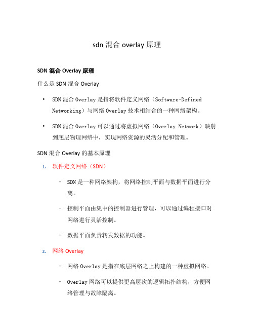
sdn 混合overlay原理SDN混合Overlay原理什么是SDN混合Overlay•SDN混合Overlay是指将软件定义网络(Software-Defined Networking)与网络Overlay技术相结合的一种网络架构。
•SDN混合Overlay可以通过将虚拟网络(Overlay Network)映射到底层物理网络中,实现网络资源的灵活分配和管理。
SDN混合Overlay的基本原理1.软件定义网络(SDN)–SDN是一种网络架构,将网络控制平面与数据平面进行分离。
–控制平面由集中的控制器进行管理,可以通过编程接口对网络进行灵活控制。
–数据平面负责转发数据的功能。
2.网络Overlay–网络Overlay是指在底层网络之上构建的一种虚拟网络。
–Overlay网络可以提供更高层次的逻辑拓扑结构,方便网络管理与故障隔离。
–Overlay网络可以通过隧道技术将底层网络抽象为一组虚拟链路。
3.SDN混合Overlay的原理–首先,在底层网络中部署SDN控制器,将网络划分为多个区域。
–然后,在每个区域中部署Overlay控制器,负责管理该区域内的虚拟网络。
–Overlay控制器通过与SDN控制器进行协商和通信,实现整个网络的协同管理。
SDN混合Overlay的优势•灵活性:SDN混合Overlay可以根据需求动态创建、修改和删除虚拟网络,灵活适应不同的应用场景。
•隔离性:SDN混合Overlay可以通过虚拟化技术实现逻辑隔离,保护网络资源免受攻击。
•可扩展性:SDN混合Overlay可以根据需要对网络进行扩展,在不影响底层网络的情况下提供更多的虚拟网络。
SDN混合Overlay的应用场景•数据中心网络:SDN混合Overlay可以提供灵活的网络划分和虚拟机迁移功能,提高数据中心网络的资源利用率。
•企业网络:SDN混合Overlay可以简化企业网络的管理,提供更好的网络隔离和安全性。
•云服务提供商:SDN混合Overlay可以帮助云服务提供商提供高效、灵活和安全的虚拟私有云服务。
rfc2674.Definitions of Managed Objects for Bridges with Traffic Classes, Multicast Filtering and Vir
Network Working Group E. Bell Request for Comments: 2674 3Com Corp. Category: Standards Track A. Smith Extreme Networks P. Langille Newbridge Networks A. Rijhsinghani Cabletron Systems K. McCloghrie cisco Systems August 1999 Definitions of Managed Objects for Bridges with TrafficClasses, Multicast Filtering and Virtual LAN ExtensionsStatus of this MemoThis document specifies an Internet standards track protocol for theInternet community, and requests discussion and suggestions forimprovements. Please refer to the current edition of the "InternetOfficial Protocol Standards" (STD 1) for the standardization stateand status of this protocol. Distribution of this memo is unlimited. Copyright NoticeCopyright (C) The Internet Society (1999). All Rights Reserved. AbstractThis memo defines a portion of the Management Information Base (MIB)for use with network management protocols in TCP/IP based internets.In particular, it defines two MIB modules for managing the newcapabilities of MAC bridges defined by the IEEE 802.1D-1998 MACBridges and the IEEE 802.1Q-1998 Virtual LAN (VLAN) standards forbridging between Local Area Network (LAN) segments. One MIB moduledefines objects for managing the ’Traffic Classes’ and ’EnhancedMulticast Filtering’ components of IEEE 802.1D-1998. The other MIBmodule defines objects for managing IEEE 802.1Q VLANs.Provisions are made for support of transparent bridging. Provisionsare also made so that these objects apply to bridges connected bysubnetworks other than LAN segments. This memo also includes several MIB modules in a manner that is compliant to the SMIv2 [V2SMI].This memo supplements RFC 1493 [BRIDGEMIB] and (to a lesser extent)RFC 1525 [SBRIDGEMIB].Bell, et al. Standards Track [Page 1]Table of Contents1 The SNMP Management Framework (3)2 Overview (4)2.1 Scope (4)3 Structure of MIBs (5)3.1 Structure of Extended Bridge MIB module (5)3.1.1 Relationship to IEEE 802.1D-1998 Manageable Objects (6)3.1.2 Relationship to IEEE 802.1Q Manageable Objects (8)3.1.3 The dot1dExtBase Group (8)3.1.4 The dot1dPriority Group (9)3.1.5 The dot1dGarp Group (9)3.1.6 The dot1dGmrp Group (9)3.1.7 The dot1dTpHCPortTable (9)3.1.8 The dot1dTpPortOverflowTable (9)3.2 Structure of Virtual Bridge MIB module (9)3.2.1 Relationship to IEEE 802.1Q Manageable Objects (9)3.2.2 The dot1qBase Group (13)3.2.3 The dot1qTp Group (13)3.2.4 The dot1qStatic Group (13)3.2.5 The dot1qVlan Group (13)3.3 Textual Conventions (13)3.4 Relationship to Other MIBs (14)3.4.1 Relationship to the ’system’ group (14)3.4.2 Relation to Interfaces MIB (14)3.4.2.1 Layering Model (15)3.4.2.2 ifStackTable (16)3.4.2.3 ifRcvAddressTable (16)3.4.3 Relation to Original Bridge MIB (16)3.4.3.1 The dot1dBase Group (16)3.4.3.2 The dot1dStp Group (17)3.4.3.3 The dot1dTp Group (17)3.4.3.4 The dot1dStatic Group (17)3.4.3.5 Additions to the Original Bridge MIB (18)4 Definitions for Extended Bridge MIB (18)5 Definitions for Virtual Bridge MIB (39)6 Acknowledgments (80)7 Security Considerations (80)8 References (81)9 Authors’ Addresses (84)10 Intellectual Property (85)11 Full Copyright Statement (86)Bell, et al. Standards Track [Page 2]1. The SNMP Management FrameworkThe SNMP Management Framework presently consists of five majorcomponents:o An overall architecture, described in an Architecture forDescribing SNMP Management Frameworks [ARCH].o Mechanisms for describing and naming objects and events for thepurpose of management. The first version of this Structure ofManagement Information (SMI) is called SMIv1 and described in STD 16, RFC 1155 [V1SMI], STD 16, RFC 1212 [V1CONCISE] and RFC 1215[V1TRAPS]. The second version, called SMIv2, is described in STD 58, RFC 2578 [V2SMI], STD 58, RFC 2579 [V2TC] and STD 58, RFC2580 [V2CONFORM].o Message protocols for transferring management information. Thefirst version of the SNMP message protocol is called SNMPv1 anddescribed in STD 15, RFC 1157 [V1PROTO]. A second version of the SNMP message protocol, which is not an Internet standards trackprotocol, is called SNMPv2c and described in RFC 1901[V2COMMUNITY] and RFC 1906 [V2TRANS]. The third version of themessage protocol is called SNMPv3 and described in RFC 1906[V2TRANS], Message Processing and Dispatching [V3MPC] and User-based Security Model [V3USM].o Protocol operations for accessing management information. Thefirst set of protocol operations and associated PDU formats isdescribed in STD 15, RFC 1157 [V1PROTO]. A second set ofprotocol operations and associated PDU formats is described inRFC 1905 [V2PROTO].o A set of fundamental applications described in SNMPv3Applications [V3APPS] and the view-based access control mechanism described in View-based Access Control Model [V3VACM].Managed objects are accessed via a virtual information store, termed the Management Information Base or MIB. Objects in the MIB aredefined using the mechanisms defined in the SMI.This memo specifies a MIB module that is compliant to the SMIv2. AMIB conforming to the SMIv1 can be produced through the appropriatetranslations. The resulting translated MIB must be semanticallyequivalent, except where objects or events are omitted because notranslation is possible (use of Counter64). Some machine readableinformation in SMIv2 will be converted into textual descriptions in Bell, et al. Standards Track [Page 3]SMIv1 during the translation process. However, this loss of machine readable information is not considered to change the semantics of the MIB.2. OverviewA common device present in many networks is the Bridge. This device is used to connect Local Area Network segments below the networklayer. These devices are often known as ’layer 2 switches’.There are two major modes defined for this bridging: Source-Route and transparent. Source-Route bridging is described by IEEE 802.5[802.5]. and is not discussed further in this document.The transparent method of bridging is defined by IEEE 802.1D-1998[802.1D] which is an update to the original IEEE 802.1D specification [802.1D-ORIG]. Managed objects for that original specification oftransparent bridging were defined in RFC 1493 [BRIDGEMIB].The original IEEE 802.1D is augmented by IEEE 802.1Q-1998 [802.1Q] to provide support for ’virtual bridged LANs’ where a single bridgedphysical LAN network may be used to support multiple logical bridged LANs, each of which offers a service approximately the same as thatdefined by IEEE 802.1D. Such virtual LANs (VLANs) are an integralfeature of switched LAN networks. A VLAN can be viewed as a group of end-stations on multiple LAN segments and can communicate as if they were on a single LAN. IEEE 802.1Q defines port-based Virtual LANswhere membership is determined by the bridge port on which dataframes are received. This memo defines the objects needed for themanagement of port-based VLANs in bridge entities.This memo defines those objects needed for the management of abridging entity operating in the transparent mode, as well as someobjects applicable to all types of bridges. Managed objects forSource-Route bridging are defined in RFC 1525 [SRBRIDGEMIB].2.1. ScopeThis MIB includes a comprehensive set of managed objects whichattempts to match the set defined in IEEE 802.1D and IEEE 802.1Q.However, to be consistent with the spirit of the SNMP Framework, asubjective judgement was made to omit the objects from thosestandards most ’costly’ to implement in an agent and least’essential’ for fault and configuration management. The omissionsare described in section 3 below.Bell, et al. Standards Track [Page 4]Historical note:The original bridge MIB [BRIDGEMIB] used the following principles for determining inclusion of an object in the BRIDGE-MIB module:(1) Start with a small set of essential objects and add only asfurther objects are needed.(2) Require objects be essential for either fault or configuration management.(3) Consider evidence of current use and/or utility.(4) Limit the total of objects.(5) Exclude objects which are simply derivable from others inthis or other MIBs.(6) Avoid causing critical sections to be heavily instrumented.The guideline that was followed is one counter per criticalsection per layer.3. Structure of MIBsThis document defines additional objects, on top of those existing in the original BRIDGE-MIB module defined in [BRIDGEMIB]: that MIBmodule is to be maintained unchanged for backwards compatibility.Section 3.4.3 of the present document contains some recommendationsregarding usage of objects in the original bridge MIB by devicesimplementing the enhancements defined here.Two MIB modules are defined here:(1) Managed objects for an extended bridge MIB module P-BRIDGE-MIB for the traffic class and multicast filtering enhancementsdefined by IEEE 802.1D-1998 [802.1D].(2) Managed objects for a virtual bridge MIB module Q-BRIDGE-MIBfor the Virtual LAN bridging enhancements defined by IEEE802.1Q-1998 [802.1Q].3.1. Structure of Extended Bridge MIB moduleObjects in this MIB are arranged into groups. Each group isorganized as a set of related objects. The overall structure andassignment of objects to their groups is shown below.Bell, et al. Standards Track [Page 5]3.1.1. Relationship to IEEE 802.1D-1998 Manageable ObjectsThis section contains a cross-reference to the objects defined inIEEE 802.1D-1998 [802.1D]. It also details those objects that arenot considered necessary in this MIB module.Some objects defined by IEEE 802.1D-1998 have been included in thevirtual bridge MIB module rather than this one: entries indot1qTpGroupTable, dot1qForwardAllTable anddot1qForwardUnregisteredTable are required for virtual bridged LANswith additional indexing (e.g. per-VLAN, per-FDB) and so are notdefined here. Instead, devices which do not implement virtualbridged LANs but do implement the Extended Forwarding Servicesdefined by IEEE 802.1D (i.e. dynamic learning of multicast groupaddresses and group service requirements in the filtering database)should implement these tables with a fixed value for dot1qFdbId (the value 1 is recommended) or dot1qVlanIndex (the value 1 isrecommended). Devices which support Extended Filtering Servicesshould support dot1qTpGroupTable, dot1qForwardAllTable anddot1qForwardUnregisteredTable.Bell, et al. Standards Track [Page 6]Extended Bridge MIB Name IEEE 802.1D-1998 Namedot1dExtBase Bridgedot1dDeviceCapabilitiesdot1dExtendedFilteringServicesdot1dTrafficClassesdot1dTrafficClassesEnableddot1dGmrpStatus .ApplicantAdministrativeControl dot1dPrioritydot1dPortPriorityTabledot1dPortDefaultUserPriority .UserPrioritydot1dPortNumTrafficClassesdot1dUserPriorityRegenTable .UserPriorityRegenerationTabledot1dUserPrioritydot1dRegenUserPrioritydot1dTrafficClassTable .TrafficClassTabledot1dTrafficClassPrioritydot1dTrafficClassdot1dPortOutboundAccessPriorityTable.OutboundAccessPriorityTabledot1dPortOutboundAccessPrioritydot1dGarpdot1dPortGarpTabledot1dPortGarpJoinTime .JoinTimedot1dPortGarpLeaveTime .LeaveTimedot1dPortGarpLeaveAllTime .LeaveAllTimedot1dGmrpdot1dPortGmrpTabledot1dPortGmrpStatus .ApplicantAdministrativeControldot1dPortGmrpFailedRegistrations .FailedRegistrationsdot1dPortGmrpLastPduOrigin .OriginatorOfLastPDUdot1dTpdot1dTpHCPortTabledot1dTpHCPortInFrames .BridgePort.FramesReceiveddot1dTpHCPortOutFrames .ForwardOutBounddot1dTpHCPortInDiscards .DiscardInbounddot1dTpPortOverflowTabledot1dTpPortInOverflowFrames .BridgePort.FramesReceiveddot1dTpPortOutOverflowFrames .ForwardOutBounddot1dTpPortInOverflowDiscards .DiscardInboundBell, et al. Standards Track [Page 7]The following IEEE 802.1D-1998 management objects have not beenincluded in the Bridge MIB for the indicated reasons.IEEE 802.1D-1998 Object DispositionBridge.StateValue not considered usefulBridge.ApplicantAdministrativeControlnot provided per-attribute(e.g. per-VLAN, per-Group).Only per-{device,port,application} control is provided in this MIB.3.1.2. Relationship to IEEE 802.1Q Manageable ObjectsThis section contains section number cross-references to manageableobjects defined in IEEE 802.1Q-1998 [802.1Q]. These objects havebeen included in this MIB as they provide a natural fit with the IEEE 802.1D objects with which they are co-located.Extended Bridge MIB Name IEEE 802.1Q-1998 Section and Name dot1dExtBase Bridgedot1dDeviceCapabilitiesdot1qStaticEntryIndividualPort 5.2 implementation optionsdot1qIVLCapabledot1qSVLCapabledot1qHybridCapabledot1qConfigurablePvidTagging 12.10.1.1 read bridge vlanconfigdot1dLocalVlanCapabledot1dPortCapabilitiesTabledot1dPortCapabilitiesdot1qDot1qTagging 5.2 implementation optionsdot1qConfigurableAcceptableFrameTypes5.2 implementation optionsdot1qIngressFiltering 5.2 implementation options3.1.3. The dot1dExtBase GroupThis group contains the objects which are applicable to all bridgesimplementing the traffic class and multicast filtering features ofIEEE 802.1D-1998 [802.1D]. It includes per-device configuration ofGARP and GMRP protocols. This group will be implemented by alldevices which implement the extensions defined in 802.1D-1998.Bell, et al. Standards Track [Page 8]3.1.4. The dot1dPriority GroupThis group contains the objects for configuring and reporting status of priority-based queuing mechanisms in a bridge. This includes per- port user_priority treatment, mapping of user_priority in frames into internal traffic classes and outbound user_priority andaccess_priority.3.1.5. The dot1dGarp GroupThis group contains the objects for configuring and reporting onoperation of the Generic Attribute Registration Protocol (GARP).3.1.6. The dot1dGmrp GroupThis group contains the objects for configuring and reporting onoperation of the GARP Multicast Registration Protocol (GMRP).3.1.7. The dot1dTpHCPortTableThis table extends the dot1dTp group from the original bridge MIB[BRIDGEMIB] and contains the objects for reporting port bridgingstatistics for high capacity network interfaces.3.1.8. The dot1dTpPortOverflowTableThis table extends the dot1dTp group from the original bridge MIB[BRIDGEMIB] and contains the objects for reporting the upper bits of port bridging statistics for high capacity network interfaces forwhen 32-bit counters are inadequate.3.2. Structure of Virtual Bridge MIB moduleObjects in this MIB are arranged into groups. Each group isorganized as a set of related objects. The overall structure andassignment of objects to their groups is shown below. Somemanageable objects defined in the original bridge MIB [BRIDGEMIB]need to be indexed differently when they are used in a VLAN bridging environment: these objects are, therefore, effectively duplicated by new objects with different indexing which are defined in the Virtual Bridge MIB.3.2.1. Relationship to IEEE 802.1Q Manageable ObjectsThis section contains section-number cross-references to manageableobjects defined in clause 12 of IEEE 802.1Q-1998 [802.1Q]. It alsodetails those objects that are not considered necessary in this MIBmodule.Bell, et al. Standards Track [Page 9]Note: unlike IEEE 802.1D-1998, IEEE 802.1Q-1998 [802.1Q] did notdefine exact syntax for a set of managed objects: the followingcross-references indicate the section numbering of the descriptionsof management operations from clause 12 in the latter document.Virtual Bridge MIB object IEEE 802.1Q-1998 Referencedot1qBasedot1qVlanVersionNumber 12.10.1.1 read bridge vlan config dot1qMaxVlanId 12.10.1.1 read bridge vlan config dot1qMaxSupportedVlans 12.10.1.1 read bridge vlan config dot1qNumVlansdot1qGvrpStatus 12.9.2.1/2 read/set garpapplicant controlsdot1qTpdot1qFdbTabledot1qFdbIddot1qFdbDynamicCount 12.7.1.1.3 read filtering d/basedot1qTpFdbTabledot1qTpFdbAddressdot1qTpFdbPortdot1qTpFdbStatusdot1qTpGroupTable 12.7.7.1 read filtering entrydot1qTpGroupAddressdot1qTpGroupEgressPortsdot1qTpGroupLearntdot1qForwardAllTable 12.7.7.1 read filtering entrydot1qForwardAllPortsdot1qForwardAllStaticPortsdot1qForwardAllForbiddenPortsdot1qForwardUnregisteredTable 12.7.7.1 read filtering entrydot1qForwardUnregisteredPortsdot1qForwardUnregisteredStaticPortsdot1qForwardUnregisteredForbiddenPortsdot1qStaticdot1qStaticUnicastTable 12.7.7.1 create/delete/readfiltering entry12.7.6.1 read permanent databasedot1qStaticUnicastAddressdot1qStaticUnicastReceivePortdot1qStaticUnicastAllowedToGoTodot1qStaticUnicastStatusdot1qStaticMulticastTable 12.7.7.1 create/delete/readfiltering entry12.7.6.1 read permanent databasedot1qStaticMulticastAddressdot1qStaticMulticastReceivePortdot1qStaticMulticastStaticEgressPortsBell, et al. Standards Track [Page 10]dot1qStaticMulticastForbiddenEgressPortsdot1qStaticMulticastStatusdot1qVlandot1qVlanNumDeletesdot1qVlanCurrentTable 12.10.2.1 read vlan configuration 12.10.3.5 read VID to FIDallocations12.10.3.6 read FID allocated toVID12.10.3.7 read VIDs allocated toFIDdot1qVlanTimeMarkdot1qVlanIndexdot1qVlanFdbIddot1qVlanCurrentEgressPortsdot1qVlanCurrentUntaggedPortsdot1qVlanStatusdot1qVlanCreationTimedot1qVlanStaticTable 12.7.7.1/2/3 create/delete/readfiltering entry12.7.6.1 read permanent database12.10.2.2 create vlan config12.10.2.3 delete vlan configdot1qVlanStaticName 12.4.1.3 set bridge namedot1qVlanStaticEgressPortsdot1qVlanForbiddenEgressPortsdot1qVlanStaticUntaggedPortsdot1qVlanStaticRowStatusdot1qNextFreeLocalVlanIndexdot1qPortVlanTable 12.10.1.1 read bridge vlanconfigurationdot1qPvid 12.10.1.2 configure PVID valuesdot1qPortAcceptableFrameTypes 12.10.1.3 configure acceptableframe types parameterdot1qPortIngressFiltering 12.10.1.4 configure ingressfiltering parametersdot1qPortGvrpStatus 12.9.2.2 read/set garp applicantcontrolsdot1qPortGvrpFailedRegistrationsdot1qPortGvrpLastPduOrigindot1qPortVlanStatisticsTable 12.6.1.1 read forwarding portcountersdot1qTpVlanPortInFramesdot1qTpVlanPortOutFramesdot1qTpVlanPortInDiscardsdot1qTpVlanPortInOverflowFramesdot1qTpVlanPortOutOverflowFramesdot1qTpVlanPortInOverflowDiscardsBell, et al. Standards Track [Page 11]dot1qPortVlanHCStatisticsTable 12.6.1.1 read forwarding portcountersdot1qTpVlanPortHCInFramesdot1qTpVlanPortHCOutFramesdot1qTpVlanPortHCInDiscardsdot1qLearningConstraintsTable 12.10.3.1/3/4 read/set/deletevlan learning constraints 12.10.3.2 read vlan learningconstraints for VIDdot1qConstraintVlandot1qConstraintSetdot1qConstraintTypedot1qConstraintStatusdot1qConstraintSetDefaultdot1qConstraintTypeDefaultThe following IEEE 802.1Q management objects have not been includedin the Bridge MIB for the indicated reasons.IEEE 802.1Q-1998 Operation Dispositionreset bridge (12.4.1.4) not considered usefulreset vlan bridge (12.10.1.5) not considered usefulread forwarding port counters (12.6.1.1)discard on error details not considered usefulread permanent database (12.7.6.1)permanent database size not considered usefulnumber of static filtering count rows inentries dot1qStaticUnicastTable +dot1qStaticMulticastTablenumber of static VLAN count rows inregistration entries dot1qVlanStaticTableread filtering entry range use GetNext operation.(12.7.7.4)read filtering database (12.7.1.1)filtering database size not considered usefulnumber of dynamic group address count rows applicable to each entries (12.7.1.3) FDB in dot1dTpGroupTableBell, et al. Standards Track [Page 12]read garp state (12.9.3.1) not considered usefulnotify vlan registration failure not considered useful(12.10.1.6)notify learning constraint violation(12.10.3.10) not considered useful3.2.2. The dot1qBase GroupThis mandatory group contains the objects which are applicable to all bridges implementing IEEE 802.1Q virtual LANs.3.2.3. The dot1qTp GroupThis group contains objects that control the operation and report the status of transparent bridging. This includes management of thedynamic Filtering Databases for both unicast and multicastforwarding. This group will be implemented by all bridges thatperform destination-address filtering.3.2.4. The dot1qStatic GroupThis group contains objects that control static configurationinformation for transparent bridging. This includes management ofthe static entries in the Filtering Databases for both unicast andmulticast forwarding.3.2.5. The dot1qVlan GroupThis group contains objects that control configuration and reportstatus of the Virtual LANs known to a bridge. This includesmanagement of the statically configured VLANs as well as reportingVLANs discovered by other means e.g. GVRP. It also controlsconfiguration and reports status of per-port objects relating toVLANs and reports traffic statistics. It also provides formanagement of the VLAN Learning Constraints.3.3. Textual ConventionsThe datatypes MacAddress, BridgeId, Timeout, EnabledStatus, PortList, VlanIndex and VlanId are used as textual conventions in thisdocument. These textual conventions have NO effect on either thesyntax nor the semantics of any managed object. Objects definedusing these conventions are always encoded by means of the rules that define their primitive type. Hence, no changes to the SMI or theSNMP are necessary to accommodate these textual conventions which are adopted merely for the convenience of readers.Bell, et al. Standards Track [Page 13]3.4. Relationship to Other MIBsAs described above, some IEEE 802.1D management objects have not been included in this MIB because they overlap with objects in other MIBs applicable to a bridge implementing this MIB. In particular, it isassumed that a bridge implementing this MIB will also implement (atleast) the ’system’ group defined in MIB-II [MIB2], the ’interfaces’ group defined in [INTERFACEMIB] and the original bridge MIB[BRIDGEMIB].3.4.1. Relationship to the ’system’ groupIn MIB-II, the ’system’ group is defined as being mandatory for allsystems such that each managed entity contains one instance of eachobject in the ’system’ group. Thus, those objects apply to theentity as a whole irrespective of whether the entity’s solefunctionality is bridging, or whether bridging is only a subset ofthe entity’s functionality.3.4.2. Relation to Interfaces MIBThe Interfaces Group MIB [INTERFACEMIB], requires that any MIB which is an adjunct of the Interfaces Group MIB, clarify specific areaswithin the Interfaces Group MIB. These areas were intentionally left vague in the Interfaces Group MIB to avoid over-constraining the MIB, thereby precluding management of certain media-types.The Interfaces Group MIB enumerates several areas which a media-specific MIB must clarify. Each of these areas is addressed in afollowing subsection. The implementor is referred to the Interfaces Group MIB in order to understand the general intent of these areas.In the Interfaces Group MIB, the ’interfaces’ group is defined asbeing mandatory for all systems and contains information on anentity’s interfaces, where each interface is thought of as beingattached to a ‘subnetwork’. (Note that this term is not to beconfused with ‘subnet’ which refers to an addressing partitioningscheme used in the Internet suite of protocols.) The term ’segment’ is used in this memo to refer to such a subnetwork, whether it be an Ethernet segment, a ’ring’, a WAN link, or even an X.25 virtualcircuit.Implicit in this Extended Bridge MIB is the notion of ports on abridge. Each of these ports is associated with one interface of the ’interfaces’ group (one row in ifTable) and, in most situations, each port is associated with a different interface. However, there aresituations in which multiple ports are associated with the sameBell, et al. Standards Track [Page 14]interface. An example of such a situation would be several portseach corresponding one-to-one with several X.25 virtual circuits but all on the same interface.Each port is uniquely identified by a port number. A port number has no mandatory relationship to an interface number, but in the simplecase a port number will have the same value as the correspondinginterface’s interface number. Port numbers are in the range(1..dot1dBaseNumPorts).Some entities perform other functionality as well as bridging through the sending and receiving of data on their interfaces. In suchsituations, only a subset of the data sent/received on an interfaceis within the domain of the entity’s bridging functionality. Thissubset is considered to be delineated according to a set ofprotocols, with some protocols being bridged, and other protocols not being bridged. For example, in an entity which exclusively performed bridging, all protocols would be considered as being bridged, whereas in an entity which performed IP routing on IP datagrams and onlybridged other protocols, only the non-IP data would be considered as being bridged. Thus, this Extended Bridge MIB (and in particular,its counters) is applicable only to that subset of the data on anentity’s interfaces which is sent/received for a protocol beingbridged. All such data is sent/received via the ports of the bridge.3.4.2.1. Layering ModelThis memo assumes the interpretation of the Interfaces Group to be in accordance with the Interfaces Group MIB [INTERFACEMIB] which states that the interfaces table (ifTable) contains information on themanaged resource’s interfaces and that each sub-layer below theinternetwork layer of a network interface is considered an interface. This document recommends that, within an entity, VLANs which areinstantiated as an entry in dot1qVlanCurrentTable by eithermanagement configuration through dot1qVlanStaticTable or by dynamicmeans (e.g. through GVRP), are NOT also represented by an entry inifTable.Where an entity contains higher-layer protocol entities e.g. IP-layer interfaces that transmit and receive traffic to/from a VLAN, theseshould be represented in the ifTable as interfaces of typepropVirtual(53). Protocol-specific types such as l3ipxvlan(137)should not be used here since there is no implication that the bridge will perform any protocol filtering before delivering up to thesevirtual interfaces.Bell, et al. Standards Track [Page 15]3.4.2.2. ifStackTableIn addition, the Interfaces Group MIB [INTERFACEMIB] defines a table ’ifStackTable’ for describing the relationship between logicalinterfaces within an entity. It is anticipated that implementorswill use this table to describe the binding of e.g. IP interfaces to physical ports, although the presence of VLANs makes therepresentation less than perfect for showing connectivity: theifStackTable cannot represent the full capability of the IEEE 802.1Q VLAN bridging standard since that makes a distinction between VLANbindings on ’ingress’ to and ’egress’ from a port: theserelationships may or may not be symmetrical whereas Interface MIBEvolution assumes a symmetrical binding for transmit and receive.This makes it necessary to define other manageable objects forconfiguring which ports are members of which VLANs.3.4.2.3. ifRcvAddressTableThis table contains all MAC addresses, unicast, multicast, andbroadcast, for which an interface will receive packets and forwardthem up to a higher layer entity for local consumption. Note thatthis does not include addresses for data-link layer control protocols such as Spanning-Tree, GMRP or GVRP. The format of the address,contained in ifRcvAddressAddress, is the same as for ifPhysAddress.This table does not include unicast or multicast addresses which are accepted for possible forwarding out some other port. This table is explicitly not intended to provide a bridge address filteringmechanism.3.4.3. Relation to Original Bridge MIBThis section defines how objects in the original bridge MIB module[BRIDGEMIB] should be represented for devices which implement theextensions: some of the old objects are less useful in such devicesbut must still be implemented for reasons of backwards compatibility. Note that formal conformance statements for that MIB module do notexist since it is defined in SMIv1.3.4.3.1. The dot1dBase GroupThis mandatory group contains the objects which are applicable to all types of bridges. Interpretation of this group is unchanged.Bell, et al. Standards Track [Page 16]。
中国电信IP城域网设备测试规范-汇聚交换机v2.0

附件4:企业秘密中国电信IP城域网设备测试规范(汇聚交换机)(V2.0)中国电信集团公司二零零六年一月目录1. 概述 (1)1.1范围 (1)1.2引用标准 (1)1.3缩略语 (2)2. 测试环境和仪表 (3)2.1测试环境 (3)2.2测试仪表 (3)3. 测试内容 (4)4. 二层交换功能测试 (4)4.1基本功能测试 (4)4.1.1 超长帧转发能力 (4)4.1.2 异常帧检测功能测试 (5)4.1.3 广播抑制功能测试 (6)4.2镜像功能 (6)4.2.1 端口镜像功能测试 (6)4.2.2 流镜像功能测试 (7)4.3生成树协议测试 (8)4.3.1 标准生成树测试 (8)4.3.2 快速生成树测试 (9)4.3.3 多生成树测试 (10)4.4VLAN堆叠功能测试 (11)4.4.1 基本功能 (11)4.4.2 扩展功能 (12)4.5端口聚合 (14)4.5.1 聚合链路数量测试 (14)4.5.2 聚合效率测试 (15)4.5.3 聚合链路收敛时间测试 (16)4.6二层组播功能测试 (17)4.6.1 UNTAGGED端口IGMP SNOOPING功能测试 (17)4.6.2 TAGGED端口IGMP SNOOPING功能测试 (18)4.6.3 组播组加入/离开时间测试 (19)4.7P RIV ATE V LAN功能测试 (20)4.8V LAN交换功能测试 (21)5. 访问控制和QOS功能 (22)5.1访问控制表方向性测试 (22)5.2二层访问控制表测试 (23)5.2.1 MAC地址访问控制表测试 (23)5.2.2 VLAN访问控制表测试 (23)5.2.4 SVLAN访问控制表测试 (25)5.3三层访问控制表功能测试 (26)5.3.1 IP地址访问控制表功能测试 (26)5.3.2 四层端口访问控制表功能测试 (26)5.4访问控制表数量及性能测试 (27)5.5业务分级 (28)5.5.1 基于VLAN ID的业务分级 (28)5.5.2 基于四层端口的业务分级 (29)5.5.3 SVLAN内外层标签802.1P优先级映射 (30)5.6优先级队列 (31)5.6.1 严格优先级队列 (31)5.6.2 轮询队列 (31)5.7速率限制 (32)5.7.1 入方向速率限制功能测试 (32)5.7.2 出方向速率限制功能测试 (33)5.7.3 速率限制颗粒度及精确性测试 (34)6. 转发性能测试 (35)6.1MAC地址学习速度 (35)6.2MAC地址表容量 (35)6.3最大VLAN数量测试 (36)6.4单端口吞吐量和时延测试 (37)6.5板内交换性能测试 (38)6.6板间交换性能测试 (39)6.7综合转发性能测试 (40)7. 可靠性和安全性 (41)7.1设备可靠性 (41)7.1.1 主控板和交换矩阵冗余 (41)7.1.2 电源冗余 (42)7.1.3 业务卡热插拔 (42)7.1.4 设备重启动时间 (43)7.2网络安全 (44)7.2.1 端口地址数量限制 (44)7.2.2 设备防ARP攻击测试 (45)7.2.3 设备防ICMP攻击测试 (45)7.2.4 设备防BPDU攻击测试 (46)8. 运行维护和网络管理 (47)8.1运行维护功能测试 (47)8.1.1 远程认证管理 (47)8.1.2 SSH登录测试 (48)8.1.3 日志记录 (48)8.1.4 DHCP Option82功能测试 (49)8.2.1 SNMPv1、SNMPv2支持测试 (50)8.2.2 SNMPv3支持测试 (50)8.2.3 SNMP访问地址限制 (51)8.2.4 MIB View安全访问控制功能测试 (52)8.2.5 SNMP Trap功能测试 (52)8.3管理信息库 (53)8.3.1 端口MIB的功能测试 (53)8.3.2 VLAN MIB的功能测试 (53)8.3.3 CPU利用率、内存占用率的功能测试 (54)8.3.4 资源管理信息功能测试 (54)8.3.5 ACL管理信息功能测试 (55)8.3.6 QOS的管理功能测试 (55)8.3.7 二层组播MIB (56)8.3.8 SVLAN MIB (56)中国电信IP城域网设备测试规范-汇聚交换机1. 概述1.1 范围本规范主要参考我国相关标准、RFC标准、国际电信联盟ITU-T相关建议以及《中国电信城域网优化改造指导意见》、《中国电信城域网设备技术规范》编制。
热值仪中文说明

List of Illustrations------------------------------------------------------------- v
Chapter 1-------------------------------------------------------------------------- 1
符号
文件符号定义
标签
说明
WARNING
包括条件、惯例和步骤必须谨慎执行, 以防人员伤害和设备损坏。
CAUTION
包括条件、惯例和步骤必须谨慎执行, 以防人员伤害和设备损坏
CAUTION
电击或高温部分危险,如不采取适当的 警告,可导致人员伤害。
CAUTION
静电感应元件,要求正确地触摸,以防 损坏。
Flo-Cal 用户手册
ii 索引
Chapter 4 --------------------------------------------------------------------------17
Installation ....................................................................................................... 17 System Mounting .............................................................................................. 17 Unpacking and Inspection .................................................................... 17 Wall Mount Preparation and Procedure ............................................... 18 Free Standing Mount Instructions ........................................................ 20 Electrical Installation......................................................................................... 21 Gas & Air Supply Installation ........................................................................... 22
Overlay云网络加速全球通信

Overlay云网络加速全球通信摘要:全球通信对“一个全球网络”提出了强烈的要求。
然而,公共互联网由于其固有机制在实现这一目标方面面临着巨大的挑战。
在本文中,我们提出了互联网第二平面,这是一个构建在全球公有云之上的通用高质量网络,以加速全球通信。
我们通过三个关键技术实现了第二平面。
首先,我们开发了一种自动拓扑规划技术,以选择最佳候选云节点。
其次,我们设计了一种新的时变路由技术来计算云网络的最佳路由。
第三,我们实现了一个新的动态传输层,通过云网络提供高质量的数据传输。
通过原型评估公有云平台上的云网络,结果表明,云网络的性能大大优于现有的底层网络,RTT 时延降低 15.2%,丢包率降低 1.9%,吞吐量提高10倍。
关键词:云网络;overlay;经济全球化和国际贸易自由化的趋势对全球通信提出了许多新的要求。
大量应用程序,如跨国公司通信、直播、线路游戏和购物等对“一个全球网络”有着强烈的需求,需要一个能够在全球提供高质量端到端服务的网络。
然而现有的公共互联网由于以下挑战无法提供如此高质量的服务。
首先,公共互联网由数千个分域网络组成。
这些分域网络由具有不同通信能力的不同网络提供商支持。
将上千个网络服务提供商联合起来,共同建立一个高质量的全球网络面临巨大挑战。
其次,互联网协议只提供了一个尽力而为的服务。
虽然这一机制简单有效,但无法提供覆盖全球的高质量服务。
第三,必须手动构建预留资源的昂贵专线,以为不同类别的业务需求提供SLA。
施工需要较长时间,涉及多个部门和区域的合作。
事实上,互联网已经做了很多工作改进,如专线、软件定义网络(SDN)[1]、内容分发网(CDN)[2]等。
这些方案虽然有效,但每一个都有局限性。
部署专线需要长期施工,成本高。
通过SDN进行路由规划主要需要新的硬件支持和现有的大规模更改网络设备。
通过CDN缓存成本高昂,通常仅限于高端资源。
本文中我们通过三个关键模块实现了云网络的原型,我们提出了基于公有云构建的云网络,它被定义为构建在覆盖全球的通用高质量网络。
论文-浅谈Overlay网络中的VxLAN技术

浅谈Overlay网络中的VxLAN技术摘要:本文针对云计算数据中心的应用场景,采用VxLAN技术解决数据中心部署虚拟化规模受4096个VLAN限制、多租户网络隔离以及应用系统无法通过自动化手段协同完成相应网络变更等问题。
深入分析并研究了VxLAN为代表的Overlay网络技术、VxLAN 网络模型,在虚拟交换机上实现了VxLAN网络技术,并优化VxLAN报文在虚拟交换机中的转发流程,最后进行了验证测试,并取得了良好效果。
关键词:VxLAN SDN Overlay网络1.引言虚拟化是在云计算环境中广泛使用的技术,虚拟机迁移是在云计算环境中实现资源灵活调度、确保高可用性等的重要手段,在云数据中心环境中为了提升对计算资源的管控能力和灵活度,对虚拟机调度边界要求越来越大,甚至会出现跨机房模块和跨数据中心的需求。
传统网络常使用的环路拓扑、STP阻塞的环境中,对于二层链路利用率不足。
尤其是在网络设备具有全连接拓扑关系时,根交换机端口拥塞严重,二层网络接入能力严重受限。
同时,传统网络中基于VLAN的区域隔离设计可以满足竖井式的应用系统部署方式,但是在云计算网路资源全面贯通、共享的环境中,4096的VLAN数量限制和MAC表项容量严重不足已经成为构建云网络的巨大障碍。
因此需要新的网络技术来解决二层网络的接入能力、VLAN数量和MAC表项不足的问题[1]。
2.Overlay技术概述2.1 Overlay技术路线近两年Overlay相关技术已经日趋成熟,并得到了广泛应用,目前主流实现的技术路线主要包括以VMware NSX和开源OpenStack Neutron为代表的面向虚拟化环境的纯软件实现方式(Host Overlay)和以Huawei AC和H3C NCFC为代表的主要面向硬件网络环境的解决方案(Network Overlay)[2]。
Host Overlay方案是利用软件实现虚拟设备(vDevice)作为Overlay网络的边缘设备和网关设备,实现隧道报文的解/封包动作。
- 1、下载文档前请自行甄别文档内容的完整性,平台不提供额外的编辑、内容补充、找答案等附加服务。
- 2、"仅部分预览"的文档,不可在线预览部分如存在完整性等问题,可反馈申请退款(可完整预览的文档不适用该条件!)。
- 3、如文档侵犯您的权益,请联系客服反馈,我们会尽快为您处理(人工客服工作时间:9:00-18:30)。
Multicasting in Overlays with Network Layer Support#355AbstractOverlay networks are virtual networks formed by cooper-ating nodes that share an underlying physical network.They represent aflexible and deployable approach for applica-tions to obtain new network semantics without modification of the underlying network,but they suffer from efficiency concerns.We present two router-based primitives that help end-hosts alleviate these inefficiencies.Packet Reflection al-lows end hosts to request that routers perform routing and duplication for certain packets.Path Painting allows end hosts to determine where their paths to a rendezvous point meet.This knowledge facilitates building overlay topolo-gies that resemble the topology of the underlying network. Both primitives can be incrementally deployed for incre-mental benefit.We show how these primitives can be used to provide an efficient application-level multicast system and provide ex-perimental results on simulated topologies to show the ben-efits provided.These results indicate that when all routers support the proposed primitives,the system incurs less than 5%overhead(in terms of link usage and latency).In ad-dition,the benefits gained from deployment are significant even at low levels.When intelligent deployment strategies are used,link usage overhead is less than30%with less than 10%deployment.Finally,these benefits apply mostly to the area local to the deployed routers,providing a deployment incentive to independent networks.1IntroductionOverlay networks are a popular method for deploying dis-tributed services without having to modify the IP protocols. Example services that have been implemented as overlay networks include multi-path and indirect-routing for high reliability[20,1],teleconference applications[12],and reliable single-source multicast[13,9,6].These overlay networks perform packet routing and duplication in edge nodes,using only IP unicast between the overlay nodes.In these systems,cooperating servers throughout the Internet act as routers in an overlay network.Just as a physical network has a topology consisting of the nodes of the network and the links between them,an overlay network has a virtual topology,which exists by the agreement of the overlay nodes.Overlays transmit packets only along the virtual links between the overlay nodes using the underlying unicast mechanism provided by IP.The overlay network approach faces two important chal-lenges.First,overlay networks operate at a disadvantage to router-based systems because they are located at the edges of the network.This drawback is both a performance prob-lem,packets going in and out of external servers waste time and network bandwidth;as well as a functional problem, overlay nodes are not in a position to observe network traf-fic that is not explicitly directed to them.For example,the IP Multicast(IPM)group joins rely on the ability of routers to observe passing messages.Second,it can be difficult to build virtual topologies that resemble the topology of the underlying network.It is ben-eficial for the virtual links of an overlay network to connect nodes that are well-connected in the underlying network. Choosing well-connected virtual links is akin to supplying a physical network with a higher bandwidth link-layer.It is also common to prefer virtual links that share as few underlying links as possible with other virtual links.This property leads to independent failures,and less duplicate traffic on underlying links.Unfortunately,it is difficult to determine these characteristics today,due to complications such as temporary network congestion,routeflaps,fire-walls,and route asymmetry.Overlays have relied on waste-ful and error-prone techniques such as continual bandwidth probes to learn about the underlying network.We will use two metrics to evaluate how efficiently an overlay network is operating.Stress indicates the number of times that a semantically identical packet traverses a given link.In IPM,stress never exceeds one.On the other hand, traditional overlay networks can not hope to achieve such efficiencies because packets being forwarded by an edge node will traverse(at least)the node’s local link twice. Stretch indicates the ratio of latency in an overlay network compared to some baseline,generally IP unicast or multi-cast.The contributions of this paper are:•Packet Reflection:A primitive for routers by which ap-plications may request packet routing and duplication to occur in the routers in order to decrease stress and stretch(Section2).•Path Painting:A primitive for routers allowing end hosts to coordinate and learn where their individual paths to a rendezvous point converge,allowing effi-cient overlay topologies to be built(Section3).•A demonstration of theflexibility allowed by these primitives in the form of example multicast systemsR2R3R4E1 1SE2R5E3Figure1:An application-level multicast distribution tree.Packets are sent from the source S1to end host E1through routers R3and R4.E1sends the packets on to E2and E3.with varying communication models(Section5),ex-amples outside of the realm of multicast,RON and i3[21],and a performance evaluation(Section6)of these uses.In contrast to related work(see Section7),packet reflec-tion and painting are incrementally deployable and don’t af-fect correctness(applications will perform correctly in the face of routing changes).The primitives are for optimiza-tion only.Overlay networks must be prepared to operate as if the primitives do not exist.When the primitives are avail-able,the network will provide explicit signaling to the ap-plication,allowing it to avoid work that has been performed in the network.2Packet ReflectionIn an overlay network each node carries out explicit uni-cast communication with its neighbors in the topology. When one overlay node forwards packets between two other nodes,that packet is transmitted on the same link multiple times as it reaches the intermediate and is retrans-mitted toward thefinal destination.The links near the in-termediate will have a stress of two,and the stretch of the packet will exceed one as time is wasted while the packet approaches and then leaves the overlay router.When multicasting on an overlay network,the stress problem is exacerbated.The forwarding node duplicates packets,forcing semantically equivalent packets to be trans-mitted on the same link,in the same direction,multiple times.In such cases,some links will have a stress equal to the number of packet duplications plus one.For exam-ple,Figure1shows a simple application-level multicasting tree in which one link,R4E1,has a stress of three,while another link,R3R4,has a stress of two.Stretch is also a problem in Figure1.E2receives pack-ets only after they have traversed seven links,rather than the three of a direct unicast.E3must wait forfive traver-sals instead of three.Assuming unit latencies,these paths represent a stretch of2.3and1.7respectively.2.1Reducing stress with reflectionIP routers perform a simple operation on most packets: when a packet arrives,lookup the destination IP address in aR2R3R4E11SE2R5E3Figure2:End host E1avoids overloading link R4E1by requesting reflect(S1→E1,1,{(E1→E2,0),(E1→E3},0)).R4will now duplicate packets for E1from S1,sending copies to E2and E3.In both duplicates the source will be E1.routing table,and use the resulting entry to choose an inter-face on which to emit the packet.An overlay node,acting as an overlay router,performs a similar operation.Over-lay routers determine the overlay address and forward the packet,using IP unicast,to the next overlay node.The next node is,again,determined by consulting a routing table.In order to perform multicasts,these routing tables may con-tain multiple next hops for a single overlay destination ad-dress.Packet reflection allows an end host to ask an appropriate router to perform routing and duplication on its behalf.In Figure2,end host E1directs a reflection request toward S1,which takes it to router R4.This optimization alleviates stress on link R4E1.In addition to performing requested reflections,routers continue to forward packets using their normal forwarding rules.Thus,E1will continue to receive all packets addressed to it.The format of a reflection request is reflect(S→D,T,{(S i→D i,t i)}.Such a request will be addressed to S,and will take advantage of routing symmetry to direct it to routers that can fulfill the request.(The real-world ef-fect of asymmetry is discussed at the end of Section5.3.) This notation should be read as,“When a reflectable packet arrives from S,destined for D,duplicate it once for each S i→D i.Rewrite the source and destination in each du-plicate and emit each,tagged with the associated t i.Emit the original packet tagged with T.”Tags are used to ensure that nodes know when their reflection requests have been honored(we will see that network asymmetry and route changes can cause packets to“miss”the router that would reflect them).Tags are described in detail in Section2.3. The operation of a router receiving a reflection request and handling packets that match the request are formalized in Rules1and2.In all rules,“address”refers to an IP address and a demultiplexingfield,similar to a TCP or UDP port. Rule1Upon agreeing to a reflection request,the router shall install a reflection table entry as per the request.An entry is keyed by source and destination addresses.A table entry contains a success tag,and a number of copy entries. Each copy entry contains new source and destination ad-dresses,and a tag for each copy.R2R3R4E1 1SE2R5E3Figure3:Router R4avoids overloading link R3R4by requesting reflect(S1→E1,2,{(E1→E2,0)).Note that the tag has been in-cremented,and a copy has been eliminated from E1’s original request. Rule2When forwarding an IP packet,if a reflectable packet(IP Protocol=REFLECT)matches a reflection table key,make one copy for each copy entry in the table entry. Each copy receives new source and destination addresses and a tag.The original packet is tagged with the success tag of the reflection table entry.All packets,including the original,are then forwarded by normal unicast rules. When end hosts initiate reflection requests,they decrease stress on the link between themselves and the nearest router to them.When routers themselves make reflection requests, stress is alleviated within the network.In Figure3,router R4takes advantage of packet reflection by propagating part of its responsibility to reflect packets.By pushing a request similar to E1’s original request on to R3,R4reduces the stress on link R3R4.If R3performs the reflection to E2,R4should not.Tags allow R4to know whether a given packet has already been reflected by R3.This mechanism is formalized in Rule3 and described in more detail in Section2.3.Rule3Upon receiving a reflection request,a router shall mark each copy entry NORMAL.NORMAL entries shall be treated as in Rule2.The router may make a new reflec-tion request that asks for some copies to made on its be-half.Requested copies are marked DEMANDED.The suc-cess tag associated with the new request is recorded in the reflection table entry for the request.The tag is the entry’s expected tag,which is distinct from the success tag to be written into the original packet before forwarding.When a packet arrives with the expected tag,DEMANDED copies are not made.2.2Anatomy of a reflection requestA request consists of a three packet:ASK,OFFER,and DE-MAND.An ASK initiates the request.It contains a list of copies that the requester would like made on its behalf.The IP destination of the ASK is the source address of the match criteria.This directs the ASK toward the source through any number of routers that do not support reflection.When the ASK reaches a router that does support reflection,the router intercepts the ASK and responds with an OFFER.An OFFER contains a subset of the copies requested in the ASK,and a cryptographically generated nonce.The sub-set of copies are those copies that the router is willing to make on the requester’s behalf.An OFFER is addressed to the destination of the match request,which not necessarily the originator of the ASK.The asker must intercept the OF-FER on its way to its destination.This is a security precau-tion that ensures that only routers that could intercept traf-fic destined for a host can request that packets for the host be duplicated and emitted to a third party.Thus no greater power to eavesdrop has been created.The nonce ensures that a router can not respond to an OFFER that it has not actually seen.The nonce should be the result of a one-way hash function run on the match criteria of the request and a router secret.The router may determine the subset of copies that it is willing to perform in any way it chooses,though Rule4is a guideline.Generally,a router should be willing to make a copy if,when consulting its own IP routing table,it de-termines that the copy would not be emitted on the same interface as a packet that meets the matching criteria of the ASK.Rule4means that a router would make a copy if doing so would decrease stress on one of its own links.Rule4A router shall offer to perform all copies in a re-flection request which will do not require that the copy and the original packet be emitted on the same interface. Alternatively,Rule5is a recursive approach to determin-ing what copies a router should offer.In this formulation, ASK packets would recursively propagate to the source, then a series of OFFER packets would propagate back to original asker.Finally,DEMAND packets would proceed to-ward the sender.The recursive approach will push requests further into the network at the cost of more network traffic during setup.Rule5After receiving an ASK,a router shall pass along the reflection request(Rule3)before offering a response. The router shall then offer to perform all copies implied by Rule4or offered by the next router.A DEMAND is thefinal phase of a reflection request,and is made by the same node that sent the ASK.A DEMAND is sent in response to an OFFER,and contains the nonce of the OFFER.It will also usually contain the same copy informa-tion as the OFFER.However,the demander may choose to eliminate some copy requests and,in some cases,must do so in order to maintain the correctness of success tags.A rule for constructing DEMAND packets is deferred until tags are described.2.3Tags confirm reflectionTags allow end-hosts and routers to determine when their reflection requests have been honored.They allow end-hosts to perform necessary duplications when the network does not.The three packet handshake of a reflection request relies on symmetry in IP routing to allow the asker to interceptR2R3R4E1 1SE2R5E3Figure4:A new physical route is brought online between S1and R4, bypassing the reflection request in R3.R4notices that it receives untagged packets and performs both copies on its own.E1is unaffected. OFFER packets.A reflection request can not propagate be-yond asymmetry.However,a reflection request will propa-gate until it reaches a router which,due to an asymmetric route,would send the OFFER through a different interface than it received its ASK.Thefinal router to accept such a re-flection request will never see packets that match the reflec-tion criteria.A mechanism to inform requesters that their reflections are not being carried out is necessary.In addition,routes in the underlying network change as a result of broken links or configuration changes.A reflection request may have propagated to a router that,after a route change,no longer sees the packets that are to be reflected. Figure4demonstrates this problem.To address this problem,packet reflection requests con-tain a tag,as do all packets forwarded by the reflection mechanism.When a router performs a reflection,it writes the value of the tag for that reflection request to the original packet,which continues on its way to the original destina-tion.If a packet is received without the appropriate tag,it is clear that duplication did not occur,so the receiver per-forms the duplication as if it had never made the reflection request.There are two important phases in the use of success tags in reflection requests.In thefirst phase,a requester must choose appropriate success tags for reflection requests.We will see that as a request propagates from router to router the success tag must be changed to avoid ambiguity.The second phase occurs when a router receives a packet for which it has agreed to perform reflection.It should either perform the entire reflection itself or determine that some part of it has already been done,and perform the rest.2.3.1Establishing tagsWhen choosing a success tag,a router must ensure that the meaning of the tag is unambiguous.A secondary goal is that the success tags in successive requests remain unchanged. Certain situations allow the same success tag to be used in successive requests without creating ing the same success tag is successive requests mitigates the dele-terious effects of route asymmetry and route changes. Edge hosts use a success tag of one when initiating a request.In Figure2,thefirst request,reflect(S1→E1,1,{(E1→E2,0),(E1→E3,0)}),requests that suc-R2R3R4E11SE2R5E3Figure5:A different underlying topology allows R4to propagate its en-tire responsibility to R3.In this situation,R3can make make its request using the same success tag that it has been asked to use.cess be indicated by writing a1to the original S1→E1 packet.Zero is reserved to indicate that no reflection has occurred yet.Reflectable packets begin with their success tag set to zero.In Figure3,E1has requested that two copies be made whenever it receives a packet from S1.R4agreed to per-form those copies,but went on to request that R3should make one of the copies.The two requests must be: reflect(S1→E1,1,{(E1→E2,0),(E1→E3,0)}) reflect(S1→E1,2,{(E1→E2,0)}) Following the second request,the E1→E2copy entry in R4will be marked DEMANDED by Rule3.The second request must change the success tag in case the S1→E1packet emitted by R3ever makes it to E1 without passing through R4.R4is ensuring that R3will not confuse E1with a claim that is not true.A success tag of1would indicate that both copies have been sent,so R3 must use a different success tag after making only one copy. Changing success tags is not always pare Figure5to Figure3.In Figure5R4has agreed to the same request from E1,but was able to go on to request that R3perform both copies on its behalf,so the tag was not changed.If the S1→E1packet emitted by R3ever makes it to E1without passing through R4with a success tag of1, E1will not be confused.The claim is accurate:both copies requested by E1have been made.The difference between these two cases is that in Fig-ure5,R3has agreed to perform the exact same reflection request that R4had previously been assigned.Under these circumstances,it is reasonable for R4to go a step further and ask that R3perform R4’s tagging operation as well. This arrangement also simplifies R4’s responsibilities.R4 has arranged matters so that its operation under Rule3has led to a degenerate case:the incoming packet’s tag is the same as the expected tag,and no copy entries are NORMAL, R4may simply forward the original packet.Rule6When propagating the request associated with a re-flection table entry,a router shall use a new tag unless all copy entries of the reflection table entry are offered by the next router.The new tag shall be chosen by incrementingthe success tag of the reflection table entry.In such a case, the expected tag will be one greater than the success tag for that entry.There is a significant advantage to avoiding unnecessary tag changes.If a new link were brought up connecting R3 directly to E1,reflection would proceed without any diffi-culty.The packet would be tagged at R3in exactly the way that E1expects,so E1would correctly detect that its re-quest had been fulfilled.The fact that R3,rather than R4, performed the duplications is irrelevant.If,instead,routers always changed success tags when propagating requests, then R4’s presence would be required between R3and E1 so that the tag could be transformed.In fact,R4may safely throw out the reflection table en-try associated with the request.This optional space opti-mization is codified in Rule7.Routers should not eliminate this state without cause,however.If a new route should be added to the network that skips R3but not R4,it would be beneficial for R4to maintain enough information to per-form the necessary duplications.If the state has been elimi-nated,the packet will not be duplicated until it reaches E1. Rule7A router that has successfully passed on an entire reflection request,thereby avoiding the creation of a new success tag by Rule6,may discard the reflection table entry associated with the request.2.3.2Using tags during reflectionOnce a router has agreed to service a reflection request,it is expected to make the appropriate copies or ensure that another router has done so.The it will write its success tag to the original packet.In the simplest case the router sim-ply performs the reflection and writes the success tag.The router will always perform the reflection when it has not made a reflection request to any other router.The packet will arrive with no success tag,the router will make the copies,and then forward the original packet to the next hop with the success tagfilled as requested.If a router has made a reflection request,then a packet may arrive with its success tag correctly set to the value pre-viously requested by the router.In this case,the local router knows that the copies labeled DEMANDED by Rule3have already been made by another router.If all copies were re-quested(and therefore marked DEMANDED)the local router will avoid making any copies.If some copies were refused by the next router(and therefore remain NORMAL)the lo-cal router will make those copies.The router then tags and forwards the original packet.If a non-zero success tag appears in a packet,but the suc-cess tag does not correspond to the value of the router’s pre-vious reflection request,then the router may draw no con-clusions about previously copied packets.As we will see later,this mismatch can happen when further routers have made requests to yet more routers,but some router that is expected to perform a reflection has been skipped by the path of the original packet.The incorrect value indicates that some reflection request was performed on the packet, but the local router cannot know what has occurred,so the entire reflection must be performed,followed by writing the success tag.The local router always writes the same success tag because it is confirming that its own reflection request has been completed.In summary,Rule8refines Rule2to account for tags.Rule8To reflect a packet that does not have a success tag corresponding to the success of its reflection table entry,a router shall make all copies,then tag and forward the orig-inal.To reflect a packet that does have a matching success tag,make all copies that are marked NORMAL,then tag and forward the original.2.3.3Tags in reflection copiesIn addition to the tag associated with the request as a whole,reflection requests also contain a tag associated with each copy.This feature is necessitated by the interaction of multiple reflection requests.Suppose that a router has accepted a request:reflect(A→B,1,{(B→C,0)}). Now,when a router observes a packet going from A→B, it sends a copy from B→C and1will be written to the A→B packet.Now the router receives another request: reflect(B→C,5,({C→D,0)}).The router now deter-mines that when it receives a packet from A→B,it must send two packets in addition to the original:B→C and C→D.The router tags the B→C packet with a5so that it is clear to the originator of the second request that its request was honored.Finally,suppose that the router emits B→C pack-ets on the same interface that it receives A→B pack-ets.In that case,it makes a request to its upstream router using the tag associated with the B→Cflow identifier: reflect(A→B,2,{(B→C,5)}).By doing so,it insures that it is upholding its contract to write a5into B→C packets.The need to associate success tags with copy en-tries is codified in Rule9.Rule9If a router contains a reflection table entry,R1,in which a copy entry,C1,matches another reflection table entry R2,the copies associated with R2should be added to the copy entries of R1.The success tag of R2should be written to C1.The newly added copy entries of R1should be marked NORMAL.A subsequent reflection request may change them to DEMANDED(Rule3).Rule9places non-zero tags in the copy entries of a reflec-tion table entry.Those non-zero tags indicate that additional copies are being made.Therefore,if they are passed on in a reflection request,the associated copies must be reflected as well.This is described in Rule10.Rule10A router shall only demand a tagged copy if it also demands the copies that are implied by that tag.3Path PaintingPath painting enables nodes to set up efficient overlay topologies that resemble the underlying network.Overlay networks generally seek to optimize two attributes of their topologies.First,nodes that are near each other in the phys-ical network should be near each other in the overlay.Sec-ond,virtual links should be,as much as possible,indepen-dent of each other in the physical network.Physical inde-pendence leads to independent failures of virtual links,and allows the overlay network to deal with network character-istics more naturally.For example,when links are indepen-dent,a clever overlay network can more easily route around a slow link.To build overlays that resemble the underlying network, nearby nodes should aggregate into small clusters.These clusters might further aggregate with nearby clusters to form larger clusters,and so on.To allow for this aggrega-tion,path painting takes advantage of the fact that,in gen-eral,the Internet is organized so that nearby nodes share most of their paths to far away nodes.This property works at many scales.Locally,the com-puters of a single university dorm share almost all of their paths,beginning with their LAN.All computers of the uni-versity also share most of their paths,though not necessarily thefirst few hops.Beyond that,all customers of the univer-sity’s ISP share paths once they reach the ISP,and so on. To use path painting,end hosts send paint requests to-ward an agreed upon rendezvous point.As the requests move toward the rendezvous point,there are two possibili-ties at each router.First,the request may arrive at a router that has no paint color associated with the request’s des-tination.In that case,the router becomes colored by the request—the source address and port are noted—and the packet is forwarded as usual.Alternatively,a request may arrive at a router that is already colored for the des-tination of the request.In that case,a notification is sent to two nodes—the source of the current request and the source of the router’s current color.The notification con-tains the addresses of both nodes,allowing them to make an application-level decision about aggregation.In addi-tion,the request is dropped unless is came from the current color of the router,allowing many nodes to paint toward a given rendezvous without overwhelming it.Figure6illustrates the interactions of three paint re-quests.Thefirst painter emits a paint request which paints all routers on the way to its destination.After that,two more painters emit paint requests.Those requests proceed only until they reach a router that has already been painted.3.1Anatomy of a paint requestA paint request begins with a REQUEST packet.A RE-QUEST packet contains two optional lists,concede and ig-nore.They are useful for directing the paint process in greater detail.See Sections3.2and3.3.The NOTIFY packet,sent in response to the REQUEST123Figure6:Three nodes,E1,E2,and E3send paint requests to a ren-dezvous,S1.E2has sent its requestfirst,so the later requests from E1 and E3are dropped when the reach a painted router.After notifications, E2knows about E1and E3.E1and E3know only of E2.contains the addresses of nodes that have sent REQUEST packets to the same destination.A REQUEST packet will contain address information about exactly one or two nodes. Thefirst address will always be the current color of the router sending the NOTIFY.When responding to a RE-QUEST from the node that is currently coloring the node, that will be the only address in the response.When respond-ing to another node,that node’s address will be the second address.A separate copy of the NOTIFY is sent to each of the painters in the response.Rule11summarizes.Rule11Upon receiving a paint request,a router consults its paint table for the packet’s IP destination.If the router is not painted,the request is forwarded normally,the router becomes painted by the requester,and a notification is sent to the requester containing only its own address.If the router was already painted,the request is dropped,and the router sends two notifications,each containing the color of the router and the address of the requester.The router’s color is listedfirst in the packet.The notifications are ad-dressed to the requester and the current color of the router.3.2ConcedeNormally,paint requests are dropped if they match a request previously made at the same router.Only one“paint color”continues on from an intersection point.Without applica-tion hints,the propagated request is arbitrarily chosen to be thefirst color observed by the router.To allow applications to choose propagation of a particu-lar request,paint requests may contain an IP address and port in a concedefield,which indicates that the request should not proceed past a node with a request that origi-nated from concede.Rules12and13provide details. Rule12When a router receives a paint request with a filled concedefield,the request isfirst treated normally,as in Rule11,including forwarding if the paint color is the router’s current paint color.In addition,if the request’s color matches the current color of the router,the router notes the value of the concession color.Rule13When a router receives a paint request from a color that matches a previously noted concession color,the。