High performance oxide fibers for metal and ceramic composites
α-Fe2O3光电催化分解水制备氢气研究进展
2017年第36卷第2期 CHEMICAL INDUSTRY AND ENGINEERING PROGRESS ·397·化工进展α-Fe2O3光电催化分解水制备氢气研究进展王开放,刘光,高旭升,贺冬莹,李晋平(太原理工大学精细化工研究所,山西太原 030024)摘要:光电化学池可以将太阳能以氢气的形式储存起来,其中稳定、廉价的催化剂是关键。
α-Fe2O3具有合适的禁带宽度,较高的理论光-电转化效率,光稳定性好,在地壳中的储量丰富,被认为是最具有发展前景的光电催化材料之一;但是它的导电性差、光生电荷寿命短、氧化反应过电位高,严重阻碍了其发展。
本文首先介绍了光电催化理论,然后重点综述了近些年α-Fe2O3纳米结构的制备技术,以及针对其不足所采用的改性方法,包括通过元素掺杂来增强α-Fe2O3的导电性,表面处理来降低氧化反应过电势或陷阱浓度,与其他材料复合来增加光生电压或催化剂表面积,最后对α-Fe2O3作为光阳极催化剂分解水制氢未来的发展前景作出展望,指出多种手段的有效结合是提高其光电流密度的重要途径。
关键词:赤铁矿;太阳能;光电催化;水解;氢气中图分类号:O614.81;O644.16;TQ116.2 文献标志码:A 文章编号:1000–6613(2017)02–0397–13 DOI:10.16085/j.issn.1000-6613.2017.02.001Hematite photoanodes for solar water splittingWANG Kaifang,LIU Guang,GAO Xusheng,HE dongying,LI Jinping (Research Institute of Fine Chemicals,Taiyuan University of Technology,Taiyuan 030024,Shanxi,China)Abstract:Photoelectrochemical cell is able to turn sunlight into stored energy conveniently in the form of hydrogen,and the stable and low-cost photoanode catalyst is crucial in this device. Hematite is considered as one of the most promising photoanode catalysts due to its suitable band gap,high theoretical solar to hydrogen efficiency,chemical stability under illumination and rich storage in earth.However,the poor conductivity,short photo-generated charge carrier lifetime and high turn-on voltage have limited the performance improvement of hematite severely. This review introduces the basic mechanism of photoelectrocatalysis and energy band excitation,then it summarizes the synthesis of nanostructure α-Fe2O3 and the improvements on the photoelectrocatalysis property of hematite in recent years,including conductivity enhancement by element doping,oxygen evolution overpotential or trap concentration reduction by surface treatment,and photo-induced voltage or specific area increase by coupling with other materials. The future developing perspectives of hematite are also presented,and multi-modified technologies are considered as important ways to improve the photocurrent density.Key words:hematite;solar energy;photoelectrocatalysis;hydrolysis;hydrogen随着全球经济的不断发展,人类对能源的需求量持续扩大,全球能源的消耗仍然是以化石能源为主,但是化石燃料储量有限、生成周期长,难以满足持续大量的需求,而且常规能源的广泛应用所引起的环境问题日益凸显。
杜邦高密度聚乙烯无纺布Tyvek(特卫强)介绍

Medical Packaging Improved by DuPont™ Tyvek®
1
在一次心脏的PTCA介入手术中,有多 少器械被打开使用?有多少风险存在?
2
三角支撑 The Triad
Goal: Safe and Efficacious Product
目标:安全和有效的产品
完整性保护
Protect Integrity • 贯穿产品的整个储运过程
• 面临被穿刺和被刺破的挑战
– 来自一个外部的物体
– 不规则或尖锐的外科器械边缘
– ……
16
2. 机械强度 – 撕裂强度
Elmendorf Tear Strength
ASTM D1424
1.0
0.8
Lbs.
0.77
0.6
0.67 0.55
11
特卫强®…为何包装至关重要 Why Using DuPont™ Tyvek®
包装材料的重要性能
Critical Performance Properties
1. 微生物阻隔 Microbial Barrier 2. 机械强度 Mechanical Properties 3. 洁净剥离 Clean Peel 4. 灭菌方式相容性 Sterilization Compatibility
• 成型硬塑盒 Preformed Rigid Trays • 模切盖材 Die Cut Lids • 三封袋 Chevron Pouch • 顶头袋 Header Bags • 成型 填充 封口 Form Fill Seal
4
简报概要
Presentation Outline
杜邦TM 特卫强®在医疗包装中的应用
C纤维
HistoryIn 1879, Thomas Edison baked cotton threads or bamboo slivers at high temperatures carbonizing them into an all-carbon fiber filament used in one of the first incandescent light bulbs to be heated by electricity.[1] In 1880, Lewis Latimer developed a reliable carbon wire filament for the incandescent light bulb, heated by electricity.[2]In 1958, Roger Bacon created high-performance carbon fibers at the Union Carbide Parma Technical Center, now GrafTech International Holdings, Inc., located outside of Cleveland, Ohio.[3] Those fibers were manufactured by heating strands of rayon until they carbonized. This process proved to be inefficient, as the resulting fibers contained only about 20% carbon and had low strength and stiffness properties. In the early 1960s, a process was developed by Dr. Akio Shindo at Agency of Industrial Science and Technology of Japan, using polyacrylonitrile (PAN) as a raw material. This had produced a carbon fiber that contained about 55% carbon. In 1960 Richard Millington of H.I. Thompson Fiberglas Co. developed a process (US Patent No. 3,294,489) for producing a high carbon content (99%) fiber using rayon as a precursor. These carbon fibers had sufficient strength (modulus of elasticity and tensile strength) to be used as a reinforcement for composites having high strength to weight properties and for high temperature resistant applicationsThe high potential strength of carbon fiber was realized in 1963 in a process developed by W. Watt, L. N. Phillips, and W. Johnson at the Royal Aircraft Establishment at Farnborough, Hampshire. The process was patented by the UK Ministry of Defence, then licensed by the NRDC to three British companies: Rolls-Royce already making carbon fiber, Morganite, and Courtaulds. Within a few years, after successful use in 1968 of a Hyfil carbon-fiber fan assembly in the Conways of the Vickers VC10s operated by BOAC,[4] Rolls-Royce took advantage of the new material's properties to break into the American market with its RB-211 aero-engine with carbon-fiber compressor blades. Unfortunately, the blades proved vulnerable to damage from bird impact. This problem and others caused Rolls-Royce such setbacks that the company was nationalized in 1971. The carbon-fiber production plant was sold off to form "Bristol Composites".In the late 1960s, the Japanese took the lead in manufacturing PAN-based carbon fibers. The 1970 joint technology agreement allowed Union Carbide to manufacture the Japan’s Toray Industries superior product and USA to dominate the market. Morganite decided that carbon-fiber production was peripheral to its core business, leaving Courtaulds as the only big UK manufacturer. Continuing collaboration with the staff at Farnborough proved helpful in the quest for higher quality and improvements in the speed of production as Courtaulds developed two main markets: aerospace and sports equipment. However Courtaulds's big advantage asmanufacturer of the "Courtelle" precursor now became a weakness. Courtelle's low cost and ready availability were potential advantages, but the water-based inorganic process used to produce it made the product susceptible to impurities that did not affect the organic process used by other carbon-fiber manufacturers.Nevertheless, during the 1980s Courtaulds continued to be a major supplier of carbon fiber for the sports-goods market, with Mitsubishi its main customer until a move to expand, including building a production plant in California, turned out badly. The investment did not generate the anticipated returns, leading to a decision to pull out of the area and Courtaulds ceased carbon-fiber production in 1991. Ironically the one surviving UK carbon-fiber manufacturer continued to thrive making fiber based on Courtaulds's precursor. Inverness-based RK Carbon Fibres Ltd concentrated on producing carbon fiber for industrial applications, removing the need to compete at the quality levels reached by overseas manufacturers.During the 1960s, experimental work to find alternative raw materials led to the introduction of carbon fibers made from a petroleum pitch derived from oil processing. These fibers contained about 85% carbon and had excellent flexural strength. Also, during this period, the Japanese Government heavily supported carbon fiber development at home and several Japanese companies such as Toray, Nippon Carbon, Toho Rayon and Mitsubishi started their own development and production. As they subsequently advanced to become market leaders, companies in USA and Europe were encouraged to take up these activities as well, either through their own developments or contractual acquisition of carbon fiber knowledge. These companies included Hercules, BASF and Celanese USA and Akzo in Europe.Since the late 1970s, further types of carbon fiber yarn entered the global market, offering higher tensile strength and higher elastic modulus. For example, T400 from Toray with a tensile strength of 4,000 MPa and M40, a modulus of 400 GPa. Intermediate carbon fibers, such as IM 600 from Toho Rayon with up to 6,000 MPa were developed. Carbon fibers from Toray, Celanese and Akzo found their way to aerospace application from secondary to primary parts first in military and later in civil aircraft as in McDonnell Douglas, Boeing and Airbus planes. By 2000 the industrial applications for highly sophisticated machine parts in middle Europe was becoming more important.Structure and propertiesCarbon fiber is frequently supplied in the form of a continuous tow wound onto a reel. The tow is a bundle of thousands of continuous individual carbon filaments held together and protected by an organic coating, or size, such as polyethylene oxide (PEO) or polyvinyl alcohol (PVA). The tow can be conveniently unwound from the reel for use. Each carbon filament in the tow is a continuous cylinder with a diameter of 5–10 micrometers and consists almost exclusively of carbon. The earliest generation (e.g. T300, HTA and AS4) had diameters of 16–22 micrometers.[5] Later fibers (e.g. IM6 or IM600) have diameters that are approximately 5 micrometers.[5]The atomic structure of carbon fiber is similar to that of graphite, consisting of sheets of carbon atoms arranged in a regular hexagonal pattern (graphene sheets), the difference being in the way these sheets interlock. Graphite is a crystalline material in which the sheets are stacked parallel to one another in regular fashion. The intermolecular forces between the sheets are relatively weak Van der Waals forces, giving graphite its soft and brittle characteristics.Depending upon the precursor to make the fiber, carbon fiber may be turbostratic or graphitic, or have a hybrid structure with both graphitic and turbostratic parts present. In turbostratic carbon fiber the sheets of carbon atoms are haphazardly folded, or crumpled, together. Carbon fibers derived from Polyacrylonitrile (PAN) are turbostratic, whereas carbon fibers derived from mesophase pitch are graphitic after heat treatment at temperatures exceeding 2200 °C. Turbostratic carbon fibers tend to have high tensile strength, whereas heat-treated mesophase-pitch-derived carbon fibers have high Young's modulus (i.e., high stiffness or resistance to extension under load) and high thermal conductivity.REFERENCESSACMA Releases “Carbon Fiber Industry Statistics”, Composites News, No. 1, 1998 SAMPE Plenary Describes “Carbon Fiber Capacity, Trends”, Composites News, No. 6, 1998Carbon fibers Seen as Having Big Long Term Growth Infrastructure is Next Big Trend Driver, “Advanced Materials & Composites”News, No. 3, 1999Composites Edge; 1992US5536486, “Carbon fibers and Nonwoven Fabrics“6. Rehabilitation Bridges: Carbon Fiber-reinforced Polymer Shows Promise for RepairingStructures, Advanced Materials & Composites News, No. 2, 19998. New Company Launches Carbon Fiber Fabrics for Decorative Applications, AdvancedMaterials & Composites News, No. 8, 1998Carbon fibers Electrical Conductivity Found to Offer New Uses, Composites News, No. 3, 1998 9Jean-Baptiste Donnet, Roop Chand Bansal, “Carbon“Fibers”, published by Marcel Dekker Inc., 1990, p370.。
光化学污染对城市大气的影响(英文)

Effects of photo-chemical smog on urban airAbstract:Summary: along with the sustained and rapid development of China's economy, fuel consumption is increasing. Atmospheric carbon monoxide, nitrogen oxides and the emissions of pollutants such as hydrocarbons are also growing rapidly, these are raw material for formation of photochemical smog. Photochemical smog, once formed, affected a wide range. Its dangers have been on the urban environment, human health, and ecological balance causing great threat. Carry out energy-saving emission reduction policies, it is imperative to control emissions of air pollutants. This article is about the production of photochemical smog, and briefly describes the hazards and prevention measures.I. The production of photochemical smogOf atmospheric nitrogen oxides and hydrocarbons react to form photochemical smog, UV irradiation. The atmosphereNitrogen oxides are mainly from fossil fuel combustion and incineration of the plant, and the transformation of agricultural soils and animal waste. Among them, with automobile exhaust gas as the main source. [1]Formation of photochemical smog:1. The condition of pollutionIndustrial emissions, vehicle exhaust emissions such as nitrogen oxides and hydrocarbons.2. Meteorological conditions2.1 strong lightNO2 photolysis is a 290~420nm ' light, therefore, likely to in summer than in winter, around noon in the day light most likely to smoke.2.2 low winds, low humidity, weather temperature inversion.3. Geographical conditionsSolar radiation is one of the main conditions, intensity of solar radiation, depending on the height of the Sun, solar radiation angle with the ground and atmospheric transparency. Therefore, the concentration of photochemical smog, except under the influence of the diurnal variation of solar radiation, but also by the latitude, altitude, season, weather and other conditions influence. Studies have shown that at 60 ~ North latitude 60 between some major cities, smog can occur. [2] II.Second, the harm of photochemical smogPhotochemical smog is strongly oxidizing, stimulate the eyes and the respiratory tract Mucosa, injuries, accelerated ageing of rubber plant leaves, and reduced visibility. Harmful to human, animal and plant and materials is mainly ozone, PAN and secondary pollutants such as Acrolein and formaldehyde. Ozone, PAN can cause rubber products such as ageing, embrittlement, makes dyes fade, and damage to paint and coatings, textile fibers and plastic products. [3]Harmful effects is mainly manifested in the following aspects:1. The risk to human and animal health:Major injury to human and animal eyes and mucous membrane irritation, headache, respiratory disorders, abnormal lung function deterioration of chronic respiratory diseases, children and so on.Ozone is a powerful oxidizing agent. In 0.1ppm concentrations, it has a special smell. And can achieve deep stimulation under the mucosa of the respiratory system, causing chemical changes, it acts as a radiation, chromosomal abnormalities, red blood cell aging. PAN, formaldehyde, Carolina and other products for people and animals such as eye, throat and nose have a stimulating effect. Their domain is0.1ppm. Photochemical smog in addition can help asthma patients asthma attack, it can cause deterioration of chronic respiratory diseases, respiratory disorders, damagethe lungs and other symptoms of long-term inhalation of antioxidants can reduce the human cell's metabolism accelerate aging. PAN was reagents may cause skin cancer. In the 1943 United States Los Angeles the first event has attracted more than 400 people dead.2. Effects of plant growth:Ozone affect the permeability of plant cells. High performance can lead to good qualities disappear, even the loss of plant genetic ability. Ozone damage to plants, skin fade at the beginning was wax-like pigment changes over time reddish-brown spots appear on the leaves. Back of PAN leaves silver gray or bronze effect plant growth and reduce the plant's resistance to pests and diseases.3. Material quality:Contributes to formation of acid rain caused by photochemical smog rubber ageing, embrittlement, makes dyes fade paint buildings and machinery from corrosion and damage coatings, textile fibers and plastic products.4. Reduce the visibility:Photochemical smog is one of the most important characteristics of atmospheric visibility--visual range is shortened. This is mainly due to the formation of photochemical smog pollution in the atmosphere caused by aerosol. The aerosol particle size within the General 0.3~1.0 μ m. Due to the size of particles is not easy because gravity deposition can actually migrate long distances suspended in the air for a long time they are consistent with Visual wavelength and scatter sunlight, thus significantly reducing the atmospheric visibility. Thus impaired the car with the safe operation of aircraft, and other transport, leading to increased traffic accidents.5. Other hazards:Photochemical smog will accelerate the aging of rubber products and cracking, corrosion of buildings and clothing and shorten its life. [4]III.The mechanism of photochemical air pollution treatmentFirst of all, to understand the cause of photochemical smogMechanism of formation of photochemical smog: [5](1) The formation of photochemical smog conditions is the presence of nitrogen oxides and carbon dioxide in the atmosphere, atmospheric temperature is low, and there is strong sunlight, this will be a complex series of reactions in the atmosphere, generating some secondary pollutants, such as aldehydes, PAN, H2O2 and O3.Photochemical smog is a chain reaction, in which the key reactions can be simply divided into 3 groups: (1) formation of NO2 photolysis of O3: Chain initiation reaction of NO2 photolysis, reaction is as follows:NO2 +HV→NO +O O +O2 +M→O3 +M NO +O3→NO2 +O2(2) Hydrocarbons (HC) oxidation activity of free radicals, such as HO, HO2, RO2. In photochemical reactions, free radical reaction plays an important role, the free radical reaction is mainly caused by NO2 and resulting from formaldehyde photolysis:NO2 + HV→NO +O RCHO + HV→RCO +HThe presence of hydrocarbons is the root cause of transformation and proliferation of free radicals:RH +O→R +HO RH + HO→R +H2O H + O2 →HO2 R + O2→RO2 RCO+O2→[RC(O)O2]Where: r-n;RO2-alkyl peroxide; RCO-acyl;[RC ((O) O2]-benzoyl peroxide.(3) Through the above channels generated HO2, RO2, [RC ((O) O2] oxidation of NO to NO2.NO +HO2 →NO2 +HO NO +RO2→NO2 +RO RO +O2 →HO2 +RCHO NO + RC(O)O2→NO2 + RC(O)O RC(O)O→R +CO2Where: RO-alkoxy;RCHO-aldehyde①main pollutants of photochemical pollution from internal combustion engineCar ownership in the world has more than 500 million vehicles, vehicle output of more than 50 million vehicles a year. In the advanced industrialized countries, car exhausts constitute the main cause of air pollution. China's rapid growth in recent years, car production, without effective ways to control vehicle exhaust emissions on atmospheric formation of great harm. NOx is the formation of photochemical smog and acid rain pollutants in the atmosphere.Vehicle exhaust is a great mobile pollution sources, management is difficult. Currently recommended is using the method of exhaust gas purification system, it is the use of catalysts reduce exhaust gas phase activation energy in the process, improve the reaction speed. Especially for NOx control. Even though the installation of electronic-controlled air compensation device, also appears cold starts, fill valve not working, slow, prolonged idling, resulting in excessive emissions [6] in response to this situation, many scholars with an atmospheric pressure non-equilibrium plasma method to eliminate pollutants in automobile exhaust NOx. Atmospheric pressure non-equilibrium plasma is fast developing interdisciplinary disciplines, it has great potential and attractive prospects. [7] Japan set Fang Zhengyi, Xiao Tian Zhezhi, Shui Yezhang have been engaged in research on non-equilibrium plasma discharge pollutants, and certain progress has been made. East and tengjingkuanyi reported by discharge plasma beam control automobile exhaust, Ox removal rate of up to 29.2%.[8]Therefore, I think that the governance of photochemical smog pollution in the atmosphere, first of all, it is necessary to control Pollutants in automobile exhaust.Internal combustion engine exhaust contains a number of components, the basic ingredients are carbon dioxide (C02), water vapor (H20), excess oxygen (02) andkeep left nitrogen (N2), which is the result after the complete combustion of the fuel and air. In addition to these basic ingredients, exhaust also contains incomplete combustion products and combustion reaction intermediates include carbon monoxide (CO), hydrocarbons (HQ), Secretary of nitrogen oxides (Ox), Sulphur dioxide (S02), solid particles and aldehydes. Total quality of these components in the exhaust gas of diesel engine as a proportion of the not less than 1% of the total emissions in a diesel engine, sometimes up to about 5% in a gasoline engine, and most of them are harmful, or has a strong pungent odor, and some still have carcinogenic effects. Exhaust of harmful components, see table 2-1:Table 2-1: all kinds of harmful exhaust componentsInternal combustion engine emission pollutants nitrogen oxides (n Ox), carbon monoxide (CO), hydrocarbons (HC) air pollution is mainly caused by substances, these pollutants on human and environmental hazards are as follows [9]1. A nitric oxide (n Ox)Nitrogen oxides in the combustion chamber under high temperature and high pressure, nitrogen and oxygen. Nitrogen oxides in the exhaust (n Ox) includes NO, N02, N203, N20, N205, and N03 and so on. After combustion, the fuel discharged from the exhaust pipes of the nitrogen oxides in about 90%-95% NO, few N02, NO is a colorless gas that is highly unlikely after the encounter with the oxygen in the atmosphere will be further oxidized to N02. N02 Brown has a strong pungent odor, n Ox react in the atmosphere to form aerosols, oxygen phthalocyanine based nitric acid, nitric acid, nitrous acid, Nitro hydrocarbons as well as highly carcinogenic nitrosamines, directly harm to humans, animals and plants, and the environment. N Ox is the main cause of photochemical smog formation in the ground.2. Carbon monoxide (CO)Carbon monoxide is a product of incomplete combustion of fuel, seriously affecting the combination of hemoglobin in human blood and oxygen, life-threatening, and participate in various chemical reactions in the atmosphere, has an important role in the formation of smoke and methane.3. Hydrocarbon (HC)Hydrocarbons, including unburned hydrocarbons and incomplete combustion of fuel, lubricating oil and its pyrolysis and partial oxidation products, such as alkanes, alkenes, aromatics, aldehydes, ketones, and hundreds of compounds. Some hydrocarbons do not react, such as methane, ethane, propane, carbon and hydrogen and other reaction (NRHC) and so on. The percentage of non-methane hydrocarbons (total hydrocarbon 100%, minus the percentage of methane is non-methane hydrocarbon ratio), the smaller the better. HC contains benzene is considered to be a carcinogen if inhalation of gaseous benzene would reduce the red and white blood cells, reducing the number of platelets, in people exposed to large amounts of benzene can cause leukemia. Of these pollutants, HC, CO and n-Ox is a major exhaust pollutants. CO and HC can improve the structure of internal combustion engine for combustion and EGR and after treatment technology is effectively controlled,advanced countries have reached discharge standards. N Ox oxidation of N2 in the temperature in the cylinder is formed only by machine processing, cumbersome and difficult to governance, become the main object of study.Second common method of controlling internal combustion engine exhaust gasIn general reduce harmful ingredients in the exhaust gas of internal combustion engines, can be solved by two ways: one is the internal purification, the other is discharging to the exhaust pipe of the cylinder exhaust gas after treatment.1. The internal purificationInternal purification consists of the following measures:⑴improved combustion chamber design, compression ratio and spray nozzles, spray to improve the efficiency of combustion.B suction system air intake preheating temperature.C ignition system delayed ignition, after shortening the flame burning time.⑷firing system using lean combustion and high energy ignition.⑸using exhaust gas recirculation system to reduce n Ox.Services implementing secondary air combustion technology of exhaust pipes.2. Treatment after purificationInternal combustion engine exhaust gas purification technology is of NO x, HC, CO gas phase emission purification, usually using oxidation and reduction methods, with the help of catalysts to convert these harmful gases into N2, H20, CO2, this purification technology has been applied to gasoline engines. In addition to the gas in a diesel engine harmful ingredients, there are made up of solid-phase soluble hydrocarbons and soot particles, these substances are not in real time in the exhaust system catalyst for purifying, suitable particulate filter must be placed in the exhaust tube collection device, when soot particles as the main body to collect micro-particles to a certain number of heaters can be used to burn.Post-processing method in internal combustion engine are described as follows: [10] ①the exhaust gas recirculation (EGR)EGR (Exhaust Gas Recirculation EGR for short) is a fraction of the combustion emissions from exhaust pipes to introduce pipe mixed with fresh air, then burn. Exhaust gas recirculation through the following three aspects lower engine combustion temperatures, decrease the formation of n-Ox:A. improving the heat capacity of the heat capacity of the gas because the CO2 is 1.5 times of the O2, more of the mixture of exhaust gas heat capacity is higher.B. reduced O2 concentration in the mixture as part of the air are replaced by exhaust gas, mixture of O2 content was reduced accordingly.C. low combustion rate above two effects that reduce engine combustion speed, increase the heat of combustion chamber, reducing the maximum burning temperature.Ternary Catalysis II [11] such an approach can also purify the three main pollutants in the exhaust of gasoline engine C0, HC and n Ox. Three-way catalytic converter, is mounted in the exhaust system is the most important machine cleaning device, it can exhaust emission of CO, HC and n Ox and other harmful gases by oxidation and reduction into harmless carbon dioxide, water and nitrogen. Dang high temperature of car exhaust through purification device Shi, ternary catalytic device in the of purification agent will enhanced CO, and HC and n Ox three species gas of activity, prompted its for must of oxidation-restore chemical reactions, which CO in high temperature Xia oxidation became colorless, and nontoxic of carbon dioxide gas; HC compounds in high temperature Xia oxidation into water (H20) and carbon dioxide; n Ox restore into nitrogen and oxygen. Three types of harmful gases into harmless gas, purification of vehicle exhaust gas.IV. ConclusionThe World Health Organization (WHO) and the United States, and Japan and many other countries have ozone and photochemical oxidant levels serve as one of the air quality index, and photochemical smog warning was issued. Environmental protection has become an important subject in sustainable economic development, harm has drawn great attention of photochemical smog. While the world's growing environmental awareness, resistance to photochemical air pollution, prevent the occurrence of photochemical smog, is conducting a worldwide reduction of energy and automobile exhaust pollution cleaning revolution.Urban air pollution is closely linked to levels of economic development, and that China is in a period of rapid development, urban air pollution has become a major environmental problem. In order to prevent outbreaks of photochemical smog, in addition to the above methods, the means of interference of executive order must also be taken in order to have better results.V、Reference[1] Kang Xihui, Liu Meiqing, principles and applications of photochemistry, Tianjin: Tianjin University Press, 1984,1~21[2] Zhang Li; Analysis on photochemical smog pollution, Shandong: 1001-3644 (2005)04-0074-03[3] the voyage, Shao kesheng, Tang Xiaoyan, Li Chin; urban photochemical smog pollution in China [j]; Journal of Peking University (natural science Edition), 1998, Z1[4] The State environmental protection administration. Ozone layer damage [DB/OL]./ztbd/gjcyr/jbcs/200408/t20040830_60877.htm, 2004-08-30[5] The concise course of Biochemistry in early Xia Jian, Beijing: higher education press, 1992,56~601[6] Wan Junhua Xia Y unqing combustion theory based Harbin ship Engineering Academy Publishing House, 1992[7] Guo Guangyong. Experimental study on dielectric barrier discharge treatment of internal combustion engine exhaust gas NOx [d]. Dalian Maritime University, 2002.[8] Li Meng. Japan is how to control air pollution [j]. Legal persons, 2014 (4): 27-30.[9] zhoulongbaoliuchangjungaozongying internal combustion engine mechanical industry publishing house, 1999.[10] Guo Guangyong. Experimental study on dielectric barrier discharge treatment of internal combustion engine exhaust gas NOx [d]. Dalian Maritime University, 2002.[11] The Chen Chong. Catalytic converter structure and performance evaluation [j]. Journal of Sichuan industrial Institute, 2001, 20 (4): 1-3.。
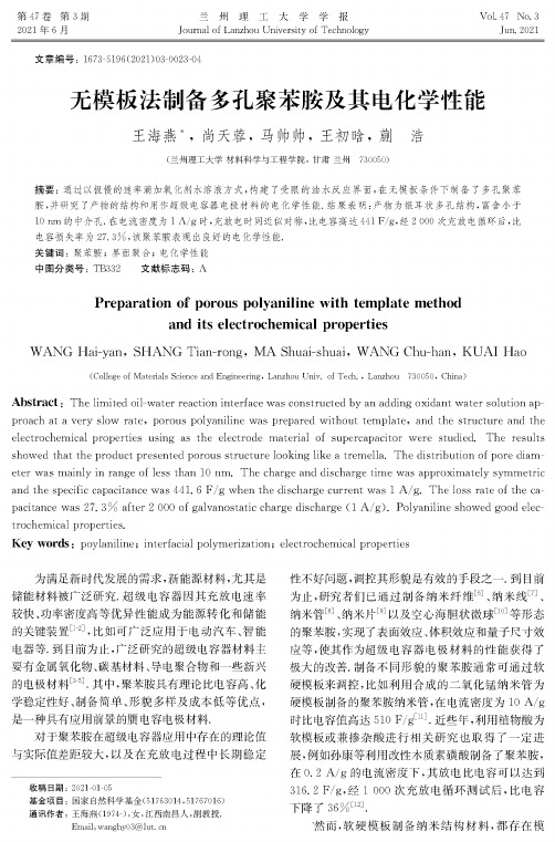
无模板法制备多孔聚苯胺及其电化学性能
兰州 理工大学学报 Journal of Lanzhou University of Technology
文章编号:1673-5196(2021)03002304
Vol. 47 No. 3 Jun2021
无模板法制备多孔聚苯胺及其电化学性能
王海燕*,尚天蓉,马帅帅,王初晗,蒯 浩
采用6700F型电子扫描显微镜(日本)进行样 品形貌的观测•采用FT-Raman Module型傅立叶 变换红外光谱仪(日本)对产物结构进行分析.活性 炭的孔结构特性测试采用北京精微高博科学技术有 限公司生产的JW-BK132F比表面及孔径分布仪. 以产物为活性物质制备电极,mol/L H2SO4水溶 液为电解液组装超级电容器,采用CHI660C电化学 工作站进行电化学测试,在一0.2〜0. 8V扫描. 1.3聚苯胺的制备
犆= 犿X △V
式中:为放电电流,A;△犜为放电时间,;犿为电 极负载活性物质的质量,g;V为放电过程中除去 电压降的电位变化,V.
0
0.2
0.4
0.6
0.8
1.0
相对压强/(P/Po)
图4聚苯胺的吸附-脱附等温曲线 Fig. 4 Adsorption/desorption isothermal curve of polyaniline
proach at a very slow rate, porous polyaniline was prepared without template, and the structure and the electrochemicalpropertiesusingastheelectrode materialofsupercapacitor werestudied Theresults showed that the product presented porous structure looking like a tremella. The distribution of pore diameterwasmainlyinrangeoflessthan10nm.Thechargeanddischargetimewasapproximatelysymmeter distribution curve of polyaniline
英文文献
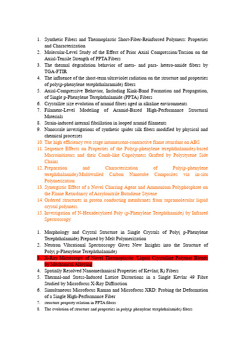
1.Synthetic Fibers and Thermoplastic Short-Fiber-Reinforced Polymers: Propertiesand Characterization2.Molecular-Level Study of the Effect of Prior Axial Compression/Torsion on theAxial-Tensile Strength of PPTA Fibers3.The thermal degradation behavior of meta- and para- hetero-amide fibers byTGA-FTIR4.The influence of the short-term ultraviolet radiation on the structure and propertiesof poly(p-phenylene terephthalaramide) fibers5.Axial-Compressive Behavior, Including Kink-Band Formation and Propagation,of Single p-Phenylene Terephthalamide (PPTA) Fibers6.Crystallite size evolution of aramid fibres aged in alkaline environments7.Filament-Level Modeling of Aramid-Based High-Performance StructuralMaterials8.Strain-induced internal fibrillation in looped aramid filaments9.Nanoscale investigations of synthetic spider silk fibers modified by physical andchemical processes10.The high efficiency two stage intumescent-contractive flame retardant on ABS11.Sequence Effects on Properties of the Poly(p-phenylene terephthalamide)-basedMacroinitiators and their Comb-like Copolymers Grafted by Polystyrene Side Chains12.Preparation and Characterization of Poly(p-phenyleneterephthalamide)/Multiwalled Carbon Nanotube Composites via in-situ Polymerization13.Synergistic Effect of a Novel Charring Agent and Ammonium Polyphosphate onthe Flame Retardancy of Acrylonitrile Butadiene Styrene14.Ordered structures in proton conducting membranes from supramolecular liquidcrystal polymers.15.Investigation of N-Hexadecylated Poly (p-Phenylene Terephthamide) by InfraredSpectroscopy1.Morphology and Crystal Structure in Single Crystals of Poly( p-PhenyleneTerephthalamide) Prepared by Melt Polymerization2.Neutron Vibrational Spectroscopy Gives New Insights into the Structure ofPoly( p-Phenylene Terephthalamide)3.X-Ray Microscopy of Novel Thermoplastic /Liquid Crystalline Polymer Blendsby Mechanical Alloying4.Spatially Resolved Nanomechanical Properties of Kevlar( R) Fibers5.Thermal-and Stress-Induced Lattice Distortions in a Single Kevlar 49 FibreStudied by Microfocus X-Ray Diffraction6.Simultaneous Microfocus Raman and Microfocus XRD: Probing the Deformationof a Single High-Performance Fiber7.structure property relation in PPTA fibers8.The evolution of structure and properties in poly(p-phenylene terephthalamide) fibers9.On-axis Microbeam Wide- and Small-Angle Scattering Experiments of a SectionedPoly( p-Phenylene Terephthalamide) Fiber10.Analysis of Interfacial Micromechanics of Model Composites Using Synchrotron MicrofocusX-Ray Diffraction一、Filament-Level Modeling of Aramid-Based High-Performance Structural Materials二、A tensile stage for high-stress low-strain fibre studies三、Surface nanostructuring of kevlar fibers by atmospheric pressure plasma-induced graft polymerization for multifunctional protective clothing四、Surface Polymerization of Poly(p-phenylene-terephthalamide) on Ag(111) Investigated by X-ray Photoelectron Spectroscopy and Scanning Tunneling Microscopy五、Activated carbon fibers with a high content of surface functional groups by phosphoric acid activation of PPTA六、Surface modification of high-performance polymeric fibers by an oxygen plasma. A comparative study of poly(p-phenylene terephthalamide) and poly(p-phenylene benzobisoxazole) 七、Effect of oxygen plasma treatment of PPTA and PBO fibers on the interfacial properties of single fiber/epoxy composites studied by Raman spectroscopy八、The effectiveness of thermal treatment for development of conductive metalized aramid fiber using supercritical fluid carbon dioxide-Fiber-metal adhesive strength improvement九、Effects of gage length, loading rates, and damage on the strength of PPTA fibers十、Preparation and Characterization of Crosslinked Copolymer Membrane Containing Sulfonated Poly(ether sulfone) and p-Phenylene Terephthalamide Segments十一、Analytical modeling of strength in randomly oriented PP and PPTA short fiber reinforced gypsum composites十二、Dynamic rheological properties and microstructures of liquid-crystalline poly(p-phenyleneterephthalamide) solutions in the presence of single-walled carbon nanotubes十三、Kevlar Functionalized Carbon Nanotubes for Next-Generation Composites十四、A study of the surface morphology of poly(p-phenylene terephthalamide) chars using scanning probe microscopy十五、Characterization of the adhesion of single-walled carbon nanotubes in poly (p-phenylene terephthalamide) composite fibres十六、The synthesis and characterisation of reactive poly(p-phenylene terephthalamide)s: A route towards compression stable aramid fibres十七、Strain-induced internal fibrillation in looped aramid filaments十八、Liquid crystal main-chain polymers for high-performance fibre applications十九、Porosity development in chars from thermal decomposition of poly(p-phenylene terephthalamide)二十、Inelastic behavior and fracture of high modulus polymeric fiber bundles at high strain-rates 二十一、Effect of chain ends on the structure of aramid oligomers二十二、Thermal transitions studied by Iso-Strain Force-Temperature Test (IFTT)二十三、Effect of absorbed moisture on the atmospheric plasma etching of polyamide fibers二十四、Modification of the pyrolysis/carbonization of PPTA polymer by intermediate isothermal treatments二十五、Surface characteristic of poly(p-phenylene terephthalamide) fibers with oxygen plasma treatment二十六、Surface characteristic of poly(p-phenylene terephthalamide) fibers with oxygen plasma treatment二十七、Physical Properties of Oriented Thin Films Formed by the Electrostatic Complexation of Sulfonated Polyaramid二十八、Effect of PPTA pre-impregnation with phosphoric acid on the porous texture of carbons prepared by CO2 activation of PPTA chars二十九、Zinc Oxide Nanowire Interphase for Enhanced Interfacial Strength in Lightweight Polymer Fiber Composites三十、Thermal- and stress-induced lattice distortions in a single Kevlar49 fibre studied by microfocus X-ray diffraction三十一、Real-time monitoring of polymer swelling on the nanometer scale by atomic force microscopy.三十二、Ordered structures in proton conducting membranes from supramolecular liquid crystal polymers.三十三、Polar ordering of linear rod-like polyamide with different linking structure of nonlinear optical chromophores三十四、Preparation of ion-track membranes of poly(p-phenylene terephthalamide): Control of pore shape by irradiation with different ion beams三十五、Electron diffraction and molecular modelling investigation of the crystal structure of poly (para-phenylene terephthalamide) form II。
reactive flash sintering method

reactive flash sintering method Reactive Flash Sintering Method: Revolutionizing Material ProcessingIntroduction:In recent decades, there has been significant progress in materials science and engineering that has allowed us to develop new and improved materials for various applications. One such innovation is the reactive flash sintering method, which has emerged as a promising technique for fabricating advanced materials with enhanced properties. This article aims to provide a comprehensive understanding of the reactive flash sintering method by discussing its principle, process, advantages, and potential applications.I. Principle of Reactive Flash Sintering:Reactive flash sintering is a novel technique that combines the principles of conventional flash sintering and reactive sintering. In flash sintering, a high electric field is applied to a material powder, causing rapid and uniform heating due to Joule heating. On the other hand, reactive sintering involves the reaction between two or more materials during the sintering process, resulting in the formation of a new phase and improved properties. In the reactiveflash sintering method, these two processes are integrated, allowing for simultaneous densification and in-situ reaction to occur.II. Process of Reactive Flash Sintering:The reactive flash sintering process consists of several steps, which are as follows:1. Material Preparation:The starting materials, typically in powder form, are carefully selected and mixed to achieve the desired composition and properties. The mixture may contain reactive components that will undergo a chemical reaction during sintering.2. Loading:The prepared powder mixture is loaded into a specially designed graphite die, which acts as both the heating element and the electrical contact.3. Application of Pressure and Electric Field:Pressure is applied to ensure proper contact between the powder particles and enhance densification. Simultaneously, a high electricfield is applied to the die, generating a strong electric current through the powder bed.4. Electrothermal Heating:The electric current passing through the graphite die generates Joule heating within the powder bed, rapidly raising its temperature. The resistance of the graphite die provides uniform heating throughout the sample.5. Reaction and Densification:As the temperature of the powder mixture increases, chemical reactions between the reactive components take place. These reactions can result in the formation of new phases, crystal growth, and enhanced properties. Additionally, the high temperature and applied pressure promote particle rearrangement and densification.6. Cooling and Post-processing:Once the desired reaction and densification are achieved, the electric field and pressure are removed, and the sample is cooled. Further post-processing steps, such as shaping, polishing, or heat treatment, can be performed as needed.III. Advantages of Reactive Flash Sintering:The reactive flash sintering method offers several advantages over conventional sintering techniques:1. Rapid Processing:Reactive flash sintering allows for significantly shorter processing times compared to traditional methods. The application of a high electric field results in rapid heating, enabling faster reaction kinetics and densification.2. Enhanced Homogeneity:The uniform heating provided by the electric current passing through the graphite die ensures enhanced homogeneity within the sintered material. This leads to improved mechanical, electrical, and thermal properties.3. Energy Efficiency:The high heating rates achieved through the Joule heating effect reduce the overall energy consumption during the sintering process. This energy efficiency makes reactive flash sintering an environmentally friendly option.4. Unique Material Combinations:The ability to perform in-situ reactions during sintering opens up new possibilities for fabricating materials that were previously difficult or impossible to produce. Complex material combinations, such as metal-ceramic composites or multi-phase alloys, can be realized using this method.IV. Potential Applications:Reactive flash sintering has the potential to revolutionize material processing and find applications in various industries. Some potential applications include:1. Advanced Ceramics:Reactive flash sintering can be used to fabricate high-performance ceramic materials with improved mechanical strength, thermal stability, and electrical conductivity. These materials can find applications in the aerospace, electronics, and energy industries.2. Metal-Ceramic Composites:The ability to reactively sinter metal and ceramic powders enables the production of metal-ceramic composites with tailoredproperties. Such composites can be utilized in the automotive, aerospace, and defense sectors due to their unique combination of characteristics.3. Sustainable Materials:The energy efficiency and reduced processing times offered by reactive flash sintering make it an ideal technique for the fabrication of sustainable, environmentally friendly materials. This includes materials for renewable energy applications, such as solid oxide fuel cells or photovoltaic devices.Conclusion:The reactive flash sintering method presents a promising avenue for the fabrication of advanced materials with enhanced properties. Its unique combination of rapid heating, in-situ reaction, and uniform densification offers numerous advantages over conventional techniques. With its potential applications spanning across various sectors, reactive flash sintering could lead to significant advancements in material science and engineering, driving innovation and improving the performance of materials indiverse industries.。
纺材英文版-再生纤维
Rayon
• Production: – Viscose process:
• • • • purified cellulose in sheet form viscose solution pumped through spinnerets into a coagulation bath solid cellulose
2
Textile fibers
Natural Fibers Manufactured Fibers
Organic manufactured fibers
Regenerative fibers
Regenerative cellulose fibers Regenerative protein fibers Regenerative synthetic fibers Synthetic fibers
Alkaline
胺氧化物体系 (NMMO)
system
Inorganic acid H2SO4,HCl, H3PO4,HNO3
Cellulose Dissolution System
多聚甲醛/二甲 基亚砜 (PF/DMSO)
Ionic liquid system
四氧化二氮/二甲基 酰胺 (N2O4/DMF(DMSO))
1
• Manufactured Fibers:
• Raw materials: natural polymers, synthetic polymers, inorganic materials ; • Properties:
• Dissolved or melt spin fibers
• History:
– 1884, the first manufactured fiber — nitrocellulose fibers – 1905, the first large-scale produced manufactured fiber—rayon – 1939, the first synthetic fiber, nylon 66
杜邦高密度聚乙烯无纺布Tyvek(特卫强)介绍

0.67
0.77
0.2
0.09
0.12
0.0
Tyvek® 2FS™ (uncoated)
Tyvek® 1059B (uncoated)
Tyvek® 1073B 44# Medical-grade 55# Coated latex-
(uncoated)
paper
saturated paper
对比于其他材料高至8倍的抗撕裂强度
• 100% 高密度聚乙烯经闪蒸工艺而成非常精细的 纤维,其直径从0.5到10微米不等 100% HDPE flash-spun very fine 0.5-10um fibers
• 采用加热加压来接合 Bonded using heat and pressure
• 无黏合剂 / 无方向性的长丝结构 No binders / nondirectional continuous form
优异的微生物阻隔性 Superior microbial Barrier
8
杜邦™ 特卫强 ® 的市场应用
Applications for DuPont™ Tyvek®
信封 Envelopes
建筑 Construction
包装 Packaging
服装 Apparel 图片印刷
Graphics
在医疗包装应用领域,请务必选用专门 用于医疗包装的B型特卫强® For medical packaging applications, please request Tyvek® Medical Packaging Styles B
Pseudomonas 假单胞菌属
Flu Virus 流感病毒
Paramecium 草履虫
【金属基复合材料】第五章,复合材料基体与增强体

Introduction
The possibility of taking advantage of particular properties of the constituent materials to meet specific demands is the most important motivation for the development of composites. The terms matrix and reinforcement are often used. The matrix is a percolating “soft” phase (with in general excellent ductility, formability and thermal conductivity) in which are embedded the “hard” reinforcements (high stiffness, hardness, and low thermal expansion). The reinforcements can be continuous or discontinuous, orientated or disorientated. The composites are classified by: (1) their matrix (polymer, ceramic, metal), (2) their reinforcement, which includes the chemical nature (oxides, carbides, nitrides), shape (continuous fibers, short fibers, whiskers, particulates) and orientation, (3) their processing routes.
石墨烯_氧化钌纳米复合材料的水热法合成及电化学电容性能_英文_沈辰飞

收稿日期:2010-08-03。
收修改稿日期:2010-11-10。
江苏省自然科学基金(No.BK2006195)资助项目。
*通讯联系人。
E -mail :jmcao@石墨烯-氧化钌纳米复合材料的水热法合成及电化学电容性能沈辰飞1郑明波2薛露平1李念武1吕洪岭1张松涛1曹洁明*,1(1南京航空航天大学材料科学与技术学院纳米材料研究所,南京210016)(2南京大学微结构国家实验室电子科学与工程学院,南京210093)摘要:通过水热法制备了石墨烯-氧化钌(G -RuO 2)纳米复合材料。
对样品进行了X 射线衍射(XRD),扫描电子显微镜(SEM),透射电子显微镜(TEM)和能量色散谱(EDS)表征。
SEM 结果表明氧化钌粒子均匀地分散在石墨烯层片上。
TEM 结果显示氧化钌纳米粒子的平均粒径约为3nm 。
对样品进行了循环伏安和充放电性能测试,结果表明在1A ·g -1的电流密度下,样品在H 2SO 4(1mol ·L -1)溶液中具有219.7F ·g -1的比电容。
关键词:氧化钌;石墨烯;纳米复合材料;电化学电容器;水热中图分类号:O613.71;O614.82+1文献标识码:A文章编号:1001-4861(2011)03-0585-05Graphene -RuO 2Nanocomposites:Hydrothermal Synthesis and ElectrochemicalCapacitance PropertiesSHEN Chen -Fei 1ZHENG Ming -Bo 2XUE Lu -Ping 1LI Nian -Wu 1L 譈Hong -Ling 1ZHANG Song -Tao 1CAO Jie -Ming *,1(1Nanomaterials Research Institute,College of Materials Science and Technology,Nanjing University ofAeronautics and Astronautics,Nanjing 210016,China )(2National Laboratory of Microstructures,School of Electronic Science and Engineering,Nanjing University,Nanjing 210093,China )Abstract:Graphene -ruthenium oxide (G -RuO 2)nanocomposite was prepared via a facile hydrothermal method.The sample was characterized by X -ray diffraction (XRD),scanning electron microscopy (SEM),transmission electron microscopy (TEM)and energy dispersive X -ray Spectroscopy (EDS).SEM result reveals homogeneous distribution of RuO 2particles on the layers of graphene sheets.TEM images demonstrate that the average size of RuO 2particles is around 3nm.The electrochemical properties of the sample were examined by cyclic voltammetry (CV)and galvanostatic charge -discharge (GC).The specific capacitance value of the sample is about219.7F·g -1at the current density of 1A ·g -1in 1mol ·L -1H 2SO 4.Key words:ruthenium oxide;graphene;nanocomposites;electrochemical capacitor;hydrothermal method0IntroductionElectrochemical capacitors (ESCs)have attracted attention as electricity storage devices due to their higher power capability and longer cycle life compared with conventional double -layer capacitors [1-2].With longcyclelife and high specic capacitance,metal oxide and carbonaceous materials have been viewed as promising electrode materials for ESCs.Metal oxides such as RuO 2[3-7],MnO 2[8-9],NiO [10-11]and Co 3O 4[12-13]have been investigated for their electrochemical behaviors.Among them,electrochemical capacitors based on RuO 2第27卷第3期2011年3月Vol .27No .3585-589无机化学学报CHINESE JOURNAL OF INORGANIC CHEMISTRY第27卷无机化学学报electrode have been widely investigated due to their superior specfic capacitance,high electrochemical reversibility,and long cycle life[14-16].In terms of carbonaceous materials,carbon nanotubes[17-18],carbon fibers[19],carbon aerogels[20]and activated carbons[21]have been studied for their electrochemical behaviors.Graphene,a new kind of carbonaceous material,has been reported with unique properties and thus has drew great interests[22-23]. Vivekchand et al.[24]evaluated the capacitive behaviors of graphene and a capacitive performance of graphene up to117F·g-1in aqueous H2SO4solution was obtained.Stoller et al.[25]studied the electrochemical behaviors of graphene as the electrode of ESCs and a specfic capacitance of135F·g-1in5.5mol·L-1KOH aqueous electrolyte was achieved.Du et al.[26]used graphene as the electrode of ESCs to obtain a stable specfic capacitance of150F·g-1under specific current of0.1A·g-1for500cycles of charge/discharge. Recently,Du et al.[27]prepared functionalized graphene sheets(FGS)using graphite oxide(GO)as precursor via a low-temperature thermal exfoliation approach in air and the products exhibited good electrochemical behaviors.To harness the good electrochemical properties of both metal oxide and graphene sheets,one possible route is to integrate these two kinds of materials into the electrodes of ESCs.The capacitive performance of the composites will be enhanced largely because most of the metal oxide can contribute pseudo-capacitance to the total capacitance apart from the double-layer capacitance from graphene sheets[28-29].Yan et al.[30] synthesized graphene-MnO2composites through the self-limiting deposition of nanoscale MnO2on the surface of graphene under microwave irradiation and studied the electrochemical behaviors of the products. Son et al.[31]fabricated NiO Resistive Random Access Memory(RRAM)nanocapacitor array on a graphene sheet.In this work,we synthesized graphene-RuO2 nanocomposite with15wt%RuO2loading via a facile hydrothermal method and studied electrochemical characteristics of the products in an aqueous electrolyte.1Experimental1.1Preparation of FGSGO was prepared by Hummers method[32].To obtain FGS,certain amount of GO was thermally exfoliated at300℃for5min under air atmosphere and denoted as FGS300[27].1.2Preparation of G-RuO2All reagents were analytical grade and used without further purification.To prepare the sample with 15wt%RuO2loading of the composite,60mg FGS300 was dissolved in60mL distilled water.After vigorous stirring,a stable suspension was obtained.1.7mL of RuCl3(0.048mol·L-1)was then dropped into the suspension with ultrasonication for30min.Then,the solution was transferred into a Teflon-lined autoclave with a capacity of100mL,and then the autoclave was sealed and maintained at180℃for6h.After cooling to room temperature,the black product was washed with distilled water for several times,and dried under vacuum at50℃for48h.1.3CharacterizationThe dimension and the morphology of the sample were observed by SEM(Gemini LEO1530)and TEM (JEOL JEM-2100).Composition of the samples was analyzed using TEM attached energy dispersive X-ray spectroscopy(EDS).XRD patterns were recorded by a Bruker D8-Advance diffractometer using Cu Kαradiation(λ=0.15418nm)with the scanning2θangles ranging from10°to80°,a graphitic monochrom at40 kV and40mA.1.4Electrochemical testsCyclic voltammetry(CV)and galvanostatic charge-discharge(GC)were done in a three-electrode experimental setup using1mol·L-1H2SO4as electrolyte.The prepared electrode,platinum foil,and saturated calomel electrode(SCE)were used as the working,counter,and reference electrodes in1mol·L-1 H2SO4aqueous solution.The preparation of the working electrode for the three-electrode system was as follows: 80wt%G-RuO2sample,15wt%acetylene black,and 5wt%polytetrafluoroethylene were well mixed,then the mixture was pressed onto a stainless steel grid under10586第3期沈辰飞等:石墨烯-氧化钌纳米复合材料的水热法合成及电化学电容性能MPa.Each electrode contained 5.0mg of G-RuO2(active material).The CV and GC measurements werecarried out on CHI440A electrochemical workstation atroom temperature,the potential ranging from0V to1.0V(vs.SCE).The GC measurement was carried out incurrent density range of0.5~5A·g-1.2Results and discussionFig.1shows the XRD patterns of FGS300and G-RuO2nanocomposite.The characteristic(002)peak ofFGS300is clearly observed on the XRD patterns ofboth FGS300and G-RuO2[27].From a comparison ofthese two XRD patterns,no obvious diffraction peakscorresponding to RuO2are found in G-RuO2.It is supposed to be due to the small size of the RuO2 particles.Fig.2(a)shows the SEM image of FGS300.The wrinkle,a characteristic feature of graphene sheets,is observed.RuO2particles are observed decorated on the graphene sheets from Fig.2(b)and Fig.2(c).The uniform distribution of RuO2particles on graphene sheets guarantees the good electrochemical properties of G-RuO2[33].The HRTEM image(Fig.3(d))reveals the good crystalline nature of the nanoparticles.Besides, the size of the RuO2particles is observed to be around 3nm,which explains the low intensity of diffraction peaks of RuO2in the XRD pattern of the composite. The selected area electron diffraction(SAED)pattern in Fig.2(e)shows a ring pattern,indicating that the obtained RuO2particles are polycrystalline,which is consistent with the HRTEM observation.Moreover,the first ring matches the(110)plane of RuO2.The other rings are very close to both structures of Ru and RuO2,which may be due to incomplete oxidation of RuCl3[34].The EDS spectrum(Fig.1(f))reveals the existence of Ru and O species,of which the Ru and O elements should be the main contribution of RuO2 phase in the composite.CV and GC were used to investigate electrochemical behaviors of G-RuO2in a three-electrode system in1mol·L-1H2SO4electrolyte.Fig.3 (a)shows the CV curves of G-RuO2at different scan rates(5~50mV·s-1)in the potential range from0to1.0 Fig.1XRD patterns of FGS300and G-RuO2nanocompositeFig.2SEM images of FGS300and G-RuO2nanocomposite(a,b),TEM and HRTEM images of G-RuO2nanocomposite(c,d), SAED pattern of G-RuO2composite(e),EDS spectrum of G-RuO2composite(f)587第27卷无机化学学报Table 1Specific capacitances of G -RuO 2(C s,composite )obtained in 1mol ·L -1H 2SO 4from GC method andcapacitance retention for G -RuO 2V.Broad current peaks and almost mirror quasi -rectangular are observed in all the CV curves over theCV potential range.This indicates that the obtained G -RuO 2nanocomposite exhibits high redox reversibility and obvious pseudocapacitance character.[35]Galvanostatic cycling of G -RuO 2is performed ata current density of 0.5~5A ·g -1as shown in Fig.3(b).The specific capacitance of G -RuO 2(C s,composite )could be calculated from the slope of the charge -dischargecurves,according to the equation:C s,composite =I Δt [36],where I is the current of charge -discharge,Δt is the time of discharge,m is the mass of active materials in the working electrode,and ΔV is 1.0V.The calculated specfic capacitances of G -RuO 2at different scan rates and the capacitance retention of the samples are listed in Table 1.The results demonstrate high capacitance retention of the sample.Besides,atthe current density of 1A ·g -1,G -RuO 2exhibits capacitance value of 219.7F ·g -1,which is muchhigher than that of FGS300(119.1F ·g -1).The specific capacitance of RuO 2(C s,Ru )could be calculated basedon the equation:C s,Ru =C s,composite -(1-ωRu )C s,FGS300ωRu[33],where ωRu is the weight fraction of RuO 2within the nanocomposite,C s,FGS300is the specific capacitance of FGS300.At the current density of 1A ·g -1,C s,Ru iscalculated to be 789.8F·g -1.The distinguishing electrochemical behaviors of G -RuO 2are due to the excellent electrochemical properties of FGS300and the contribution of pseudocapacitance by RuO 2.With nanoporous structure,the obtained FGS300has fully accessible surface to electrolyte ion because both sides of a broad range of graphene sheets can be exposed to the electrolyte and contribute to capacitance [27].Furthermore,the residual functional groups on the surface of FGS may improve the hydrophilicity of electrode,which helps the RuO 2particles to be loaded onto the surface of FGS300.The RuO 2and the residual functional groups on graphene sheets all contribute to the pseudocapacitance and thus enhance the overall capacitance value of the composites.Fig.3(a)Cyclic voltammograms of G -RuO 2obtained at different scan rates.(b)Galvanostatic dischargecurves of G -RuO 2obtained at different current densities and FGS300at a current density of 1A ·g -1G -RuO 2233.6219.7200.7176.875.70.5A·g -11A ·g -12A ·g -15A ·g -1Sample C s,composite /(F ·g -1)Capacitance retention /%3ConclusionIn summary,graphene -RuO 2nanocomposite wasprepared via a facile hydrothermal method.The SEMand TEM characterizations reveal homogeneous distribution of RuO 2particles on graphene sheets.High capacitance value and capacitance retention of the composite are shown by capacitive behaviors of G -588第3期RuO2.References:[1]Winter M,Brodd R J.Chem.Rev.,2004,104:4245-4269[2]Pandolfo A G,Hollenkamp A F.J.Power Sources,2006,157:11-27[3]WANG Xiao-Feng(王晓峰),WANG Da-Zhi(王大志),LIANGJi(梁吉),et al.Acta Phys.-Chim.Sin.(Wuli Huaxue Xuebao), 2002,18(8):750-753[4]Hu C C,Chen W C,Chang K H.J.Electrochem.Soc.,2004,151:A281-A290[5]Fang W C,Huang J H,Chen L C,et al.J.Power Sources,2006,160:1506-1510[6]Sugimoto W,Yokoshima K,Murakami Y,et al.Electrochim.Acta,2006,52:1742-1748[7]ZHENG Yan-Zhen(郑言贞),ZHANG Mi-Lin(张密林),CHEN Ye(陈野),et al.Chinese J.Inorg.Chem.(Wuji Huaxue Xuebao),2007,23(4):630-634[8]Toupin M,Brousse T,Belanger D.Chem.Mater.,2004,16:3184-3190[9]Lee H Y,Goodenough J B.J.Solid State Chem.,1999,144:220-223[10]Zheng Y Z,Ding H Y,Zhang M L.Mater.Res.Bull.,2009,44:403-407[11]Patil U M,Salunkhe R R,Gurav K V,et al.Appl.Surf.Sci.,2008,255:2603-2607[12]Cui L,Li J,Zhang X G.J.Appl.Electrochem.,2009,39:1871-1876[13]Shinde V R,Mahadik S B,Gujar T P.Appl.Surf.Sci.,2006,252:7487-7492[14]Zheng J P,Jow T R.J.Electrochem.Soc.,1995,142:L6-L8[15]Zheng J P,Jow T R.J.Power Sources,1996,62:155-159[16]Sugimoto W,Iwata H,Murakami Y,et al.J.Electrochem.Soc.,2004,151:A1181-A1187[17]Ma R Z,Liang J,Wei B Q,et al.Bull.Chem.Soc.Jpn.,1999,72:2563-2566[18]MI Hong-Yu(米红宇),ZHANG Xiao-Gang(张校刚),L譈Xin-Mei(吕新美),et al.Chinese J.Inorg.Chem.(Wuji Huaxue Xuebao),2007,23(1):159-163[19]Xu B,Wu F,Chen R J,et al.J.Power Sources,2010,195:2118-2124[20]Li J,Wang X Y,Huang Q H,et al.J.Power Sources,2006,158:784-788[21]Bispo-Fonseca I,Aggar J,Sarrazin C,et al.J.Power Sources,1999,79:238-241[22]Novoselov K S,Geim A K,Morozov S V,et al.Science,2004,306:666-669[23]Stankovich S,Dikin D A,Dommett G H B,et al.Nature,2006,442:282-286[24]Vivekchand S R C,Rout C S,Subrahmanyam K S,et al.J.Chem.Sci.,2008,120:9-13[25]Stoller M D,Park S J,Zhu Y W,et al.Nano Lett.,2008,8:3498-3502[26]Du X,Guo P,Song H H,et al.Electrochim.Acta,2010,55:4812-4819[27]Du Q L,Zheng M B,Zhang L F,et al.Electrochim.Acta,2010,55:3897-3903[28]Kalpana D,Omkumar K S,Kumar S S,et al.Electrochim.Acta,2006,52:1309-1315[29]Lee B J,Sivakkumar S R,Ko J M,et al.J.Power Sources,2007,168:546-552[30]Yan J,Fan Z J,Wei T,et al.Carbon,2010,48:3825-3833[31]Son J Y,Shin Y H,Kim H,et al.ACS Nano,2010,4:2655-2658[32]Hummers W S,Offeman R E.J.Am.Chem.Soc.,1958,80:1339-1339[33]Yuan C Z,Chen L,Gao B,et al.J.Mater.Chem.,2009,19:246-252[34]Fang W C,Chyan O,Sun C L,et mun.,2007,9:239-244[35]Wen J G,Zhou Z T.Mater.Chem.Phys.,2006,98:442-446[36]Zheng M B,Cao J,Liao S T,et al.J.Phys.Chem.C,2009,113:3887-3894沈辰飞等:石墨烯-氧化钌纳米复合材料的水热法合成及电化学电容性能589。
陶瓷基复合材料

8
3 Application and development prospect of ceramic matrix composites
3.1 Ceramic matrix composites applications in industry
Ceramic matrix composites have excellent high temperature performance,
7
Silicon nitride Series Fiber. They are actually composite ceramic fibers from the Si, N, C, and so on 0 composition. Such fibers also through organic polymer Precursor legal,Its performance similar to silicon carbide fibers .
5
(2). ceramic matrix composites
reinforced body
Ceramic matrix composites reinforced body, the body is often referred to as toughness.。 From the geometry of the reinforcement fibers can be divided into (long, short fibers), three types of whiskers and particles.
9
In the cutting tools, SiCw fine particles of toughening Al2O3 ceramic composite materials have been successfully used for industrial and manufacturing cutting tool 。Below SiCw prepared by pressing the
石墨烯制备及其在新能源汽车锂离子电池负极材料中的应用
石墨烯制备及其在新能源汽车锂离子电池负极材料中的应用田晓鸿(西安航空职业技术学院,西安710089)摘要:新能源汽车锂离子电池对于负极材料的节能环保性要求较高,而石墨烯作为新型的碳材料,因低成本、高性能而成为新型的负极材料,而针对氧化石墨法制备流程复杂、存在污染性,且制成的微米级团聚颗粒石墨烯电化学性能受限问题,文章采用机械液相剥离的规模化制备工艺,将石墨烯与石墨复合制备成石墨烯复合材料,通过实验方法测定其作为锂离子电池负极材料的电化学应用性能,结果表明与石墨复合后,可有效优化石墨烯负极材料的使用性能,更好的满足新能源汽车发展要求。
关键词:石墨烯;负极材料;电化学性质;锂离子电池中图分类号:U469.72;TM912文献标识码:A文章编号:1001-5922(2021)01-0183-04 Preparation of Graphene and Its Application as Anode Materials for Lithium Ion Batteries of New Energy VehiclesTian Xiaohong(Xi'an Aeronautical Polytechnic Institute,Xi'an710089,China)Abstract:New energy automobile lithium-ion battery has high requirements for energy-saving and environmental protection of anode materials.Graphene,as a new carbon material,has become a new type of anode material due to its low cost and high performance.However,in view of the complicated preparation process of the graphite oxide method,the presence of pollution,and the limited electrochemical performance of the micron-sized agglomerated particles,this paper adopts the large-scale preparation process of mechanical liquid phase exfoliation to prepare graphene and graphite composites into Graphene composite material,through the experimental method to determine its electrochemical application performance as a lithium-ion battery anode material.The results show that the per⁃formance of graphene anode material can be effectively optimized after compounding with graphite,which can bet⁃ter meet the development requirements of new energy vehicles.Key words:graphene;anode material;electrochemical properties;lithium ion battery0引言随着电动汽车技术及保有量的不断发展,为实现节能减排的目的,对锂离子电池制备及使用性能提出了更高的要求。
高分子专业英语

单词engineeringmaterials 工程材料ductile 延展metallic materials 金属材料durable 耐久的ferrous alloys 黑色金属合金合金quote 引用援引non-ferrous metals 有色金属eminently 杰出地organic polymer materials 有机高分子材料rust 生锈plastic 塑料precipitation 沉淀沉积rubber 橡胶dislocation 位错synthetic fibers 合成纤维arbitrary 独断的,任意的inorganic non-metallic materials 无机非金属材料smelt 熔炼,精炼composite materials 复合材料Intricate 复杂的,精巧的wrought iron 熟铁combination 结合,化合物pig iron 生铁ductile 易延展的four general types of cast iron 铸铁的四种类型low ductility 低延展性ductile iron 球墨铸铁tough 艰难的gray iron 灰铸铁toughness 韧性white iron 白口铸铁porosity 孔隙度,气孔,气泡malleable iron 可锻铸铁insulating 绝缘alloying elements 合金元素flexible 灵活的chromium 铬corrosion resistance 抗腐蚀性nickel 镍lightweight 轻impurity 杂质reduce 还原,减少majority 多数weight reduction of vehicle 汽车轻量化wool fibres 毛纤维automobile bodies 汽车车身the sheep 羊cutlery 餐具silk fibres 丝纤维springs 弹簧silkworms 蚕slip systems 滑移性cementite 渗碳体oxide 氧化物proteins 蛋白质spheroidal graphite 球状石墨varnish 清漆ballbearing 滚珠轴承pigment 颜料dislocation motion 位错的运动solvent 溶剂precipitation hardening 沉积硬化additives 添加剂balance 平衡paint 油漆cultivate 培养drying oils 干燥油shatterproof 碎cure 固化against 反对cured or dried 固化或干燥compared to 相比ancient times 古代aesthetic appeal 艺术感染力millennia 千年more dense 更密集的arbitrary boundary 任意边界判断1.The name “cast iron”derives from the fact that there is only iron in cast irons2.There are a lot of alloys in which there is no iron.3.3.Tungsten can bear the temperature of 2000℃in air.4.There are more than one step in the process to make a plstic product。
超高性能混凝土抗折强度尺寸效应
第48卷第11期2020年11月硅酸盐学报Vol. 48,No. 11November,2020 JOURNAL OF THE CHINESE CERAMIC SOCIETY DOI:10.14062/j.issn.0454-5648.20200049超高性能混凝土抗折强度尺寸效应苏捷1,2,史才军1,2,秦红杰1,张祥1(1. 湖南大学绿色先进土木工程材料及应用技术湖南省重点实验室,长沙 410082;2. 湖南大学土木工程学院,长沙 410082)摘要:通过3个强度等级、2种钢纤维类型和4组钢纤维掺量超高性能混凝土(UHPC)小梁试件的抗折试验,研究了强度等级、钢纤维类型和体积掺量对超高性能混凝土抗折强度及尺寸效应的影响。
结果表明:随UHPC强度等级的增加,小梁试件抗折强度尺寸效应趋于明显,R160级试件抗折强度尺寸效应约为R120试件的1.26倍。
钢纤维掺量对UHPC抗折强度尺寸效应有较大影响,钢纤维掺量越大,尺寸效应越明显,掺入3% (体积分数)平直型钢纤维和端勾型钢纤维的R120级UHPC 小梁试件抗折强度尺寸效应比未掺加钢纤维的试件提高了71%和78%。
建议了UHPC抗折强度尺寸换算系数,提出了UHPC 抗折强度尺寸效应律计算公式。
关键词:超高性能混凝土;抗折强度;尺寸效应;钢纤维中图分类号:TU5 文献标志码:A 文章编号:0454–5648(2020)11–1740–07网络出版时间:2020–09–18Scale Effect of Flexural Strength on Ultra-high Performance ConcreteSU Jie1,2, SHI Caijun1,2, QIN Hongjie1, ZHANG Xiang1(1. Key Laboratory for Green & Advanced Civil Engineering Materials and Application Technology of Hunan Province, HunanUniversity, Changsha 410082, China; 2. College of Civil Engineering, Hunan University, Changsha 410082, China) Abstract: The flexural strength of ultra-high performance concrete prism specimens with three kinds of strength grades, two types of steel fibers and four groups of fiber contents was determined to investigate the effects of strength grade, steel fiber and fiber content on the flexural strength and its size effect of ultra-high performance concrete. The results show that the size effect of the flexural strength becomes more obvious as the strength grade increases. The scale effect of the flexural strength of the specimen with a strength grade of R160 is 1.26 times greater than that of the specimen with a strength grade of R120. The content of steel fiber has an effect on the size effect of the flexural strength. The larger the content of steel fiber is, the more pronounced the size effect will be. The flexural strength of specimens with straight fiber and hook fiber and strength grade of R120 at a fiber content 3% (volume fraction) is 71% and 78% greater than that of the specimens without steel fiber reinforcement, respectively. The size conversion factor for the flexural strength of ultra-high performance concrete with different strength grades was given. The calculation formulas for the size effect law of the flexural strength of ultra-high performance concrete were proposed.Keywords: ultra-high performance concrete; flexural strength; size effect; steel fiber超高性能混凝土(UHPC)[1‒2]是近年发展起来的一种新型水泥基复合材料,由Rhodia、Lafarge、Bouygue和VSL共同开发[3]。
己二酸的工艺流程

己二酸的工艺流程The production process of ethylene glycol involves several steps to ensure its successful production. The first step involves the hydration of ethylene oxide, which is typically carried out using a catalyst to speed up the reaction. This step is crucial as it determines the yield and quality of the ethylene glycol produced.乙二醇的生产过程需要经历多个步骤,以确保成功生产。
第一步涉及乙烯氧化物的水合作用,通常使用催化剂加速反应。
这一步骤至关重要,因为它决定了生产乙二醇的产量和质量。
Following the hydration reaction, the resulting ethylene glycol mixture is then purified through a series of distillation processes to separate different by-products and impurities. This purification step is essential to obtain high-purity ethylene glycol for industrial applications, as any impurities can affect the performance of the final product.在水合反应之后,通过一系列蒸馏过程净化得到的乙二醇混合物,以分离不同的副产物和杂质。
这个纯化步骤对于获得用于工业应用的高纯度乙二醇至关重要,因为任何杂质都会影响最终产品的性能。
化学强碱英文大全
化学强碱英文大全Sodium hydroxide, also known as caustic soda or lye, is a powerful chemical compound with a wide range of industrial and domestic applications. As one of the most commonly used strong bases, it is a crucial component in numerous manufacturing processes and household products. This essay aims to provide a comprehensive overview of the chemical properties, production methods, and diverse applications of sodium hydroxide.Sodium hydroxide is a white, crystalline solid with the chemical formula NaOH. It is a highly reactive and corrosive substance that readily dissolves in water, forming a clear, colorless solution. The high pH of a sodium hydroxide solution, typically ranging from 13 to 14, makes it a powerful base capable of neutralizing acids and breaking down organic matter.The production of sodium hydroxide is primarily achieved through the electrolysis of brine, a process known as the chlor-alkali process. In this method, a concentrated salt solution is subjected to an electric current, which splits the sodium chloride (NaCl) molecules into sodium ions (Na+) and chloride ions (Cl-). The sodium ions then react with water to form sodium hydroxide and hydrogen gas. Thisprocess is widely used in industrial settings due to its efficiency and the high purity of the resulting sodium hydroxide.One of the most significant applications of sodium hydroxide is in the chemical industry. It is a crucial raw material in the production of a wide range of chemicals, including soap, detergents, paper, and textiles. In the soap-making process, sodium hydroxide reacts with fatty acids to form soap, which is then used in various personal care and cleaning products. Similarly, in the paper industry, sodium hydroxide is used to break down cellulose fibers, allowing for the production of high-quality paper.Another important application of sodium hydroxide is in the production of aluminium. During the Bayer process, sodium hydroxide is used to extract alumina (aluminum oxide) from bauxite ore, which is then further processed to obtain pure aluminium. This process is vital for the global aluminium industry, as it provides a reliable and cost-effective source of the metal.In the field of water treatment, sodium hydroxide plays a crucial role in adjusting the pH of water and wastewater. By adding sodium hydroxide to acidic water, the pH can be raised to a more neutral or alkaline level, making the water safer for human consumption or industrial use. This process is particularly important in the treatment of drinking water and the management of industrial effluents.Sodium hydroxide also finds application in the pharmaceutical and personal care industries. It is used as a pH regulator in various drug formulations, ensuring the stability and effectiveness of the active ingredients. Additionally, sodium hydroxide is a key component in the production of certain cosmetic and personal care products, such as shampoos, toothpastes, and skin care products.In the agricultural sector, sodium hydroxide is employed as a soil amendment, helping to adjust the pH of acidic soils and improve nutrient availability for plant growth. It is also used in the production of certain fertilizers, contributing to the overall productivity of agricultural systems.Despite its numerous beneficial applications, sodium hydroxide is a hazardous substance that requires careful handling and storage. It is a strong irritant and can cause severe burns to the skin and eyes upon contact. Proper safety protocols, including the use of personal protective equipment, must be followed when working with sodium hydroxide to minimize the risk of exposure and injury.In conclusion, sodium hydroxide is a versatile and indispensable chemical compound that plays a crucial role in a wide range of industries and applications. From its use in the production of various chemicals and materials to its importance in water treatment andagriculture, sodium hydroxide has become an integral part of modern industrial and domestic processes. As the demand for this powerful base continues to grow, it is essential to maintain a thorough understanding of its properties, production methods, and safe handling practices to ensure its responsible and effective utilization.。
瑞德西韦的密度泛函和分子对接研究
Visualizer20. 1. 0( https: / / www. 3dsbiovia. com / ) 和 Pymol 软件包
中被描绘为详细的配体 - 蛋白相互作用ꎮ 图 7 给出了配体与
受体对接位置的详细信息. 对接结果表明ꎬ瑞德西韦对 RNA 聚
的图形( b) 表示ꎮ
图ꎮ 从 MEP 结构中识别出其亲电和亲核反应位点ꎮ MEP 表
面静电势的不同值用不同的颜色映射:红色、蓝色分别代表静
MEP 与电子密度有关ꎬ对于理解亲电、亲核反应以及氢键
[9]
电势最正、最负的区域. MEP 的负( 蓝色) 区域与亲电性有关ꎬ而
刘雪莹ꎬ等:瑞德西韦的密度泛函和分子对接研究
3. 4 约化密度梯度( RDG)
RDG 是电子密度及其一阶导数ꎬ通过将 ρ( r) 映射为 λ2 ꎬ就
可以理解分子中存在的相互作用的性质和强度ꎮ λ2 符号用来
区分排斥( λ2 > 0ꎬ 无 键) 和 吸 引 ( λ2 < 0ꎬ 成 键) 相 互 作 用 [9] ꎮ
分子对接结果显示ꎬ瑞德西韦与抗 COVID - 19 药物潜在作用靶点具有较强的亲和力ꎮ
关键词:瑞德西韦ꎻ密度泛函( DFT) ꎻ前线轨道( FMO)
中图分类号:R914. 5 文献标识码:A 文章编号:1008 - 021X(2021)10 - 0051 - 03
Dendity Functional and Molecular Docking Study of Remdesivir
1. 696
2. 638
1. 298
2. 135
4. 434
新材料产业“十二五”重点产品目录 英文翻译

The Important Product Catelogue for the New Material Industry during “12th Five-Year” PeriodSpecial metal functional materialsA.Rare earth functional materialsa.Rare earth magnet materialsb.Rare earth luminescent materialsc.Rare earth hydrogen storage materialsd.Rare earth catalytic materialse.Other rare earth functional materialsB.Rare metallic materialsa.T ungsten molybdenum materialb.T antalum and niobium materialc.Nuclear grade rare metallic materialsd.Rare and noble metallic materialsC.Semiconductor materialsa.Silicone materialsb.New semiconductor materialsc.Film grade photovoltaic materialsD.Other functional alloysa.High performance target materialsb.Advanced energy storage materialsc.New copper alloysd.Hard alloy materialse.New metal fiber porous materialsf.Metal powder materialsg.OthersHigh end metallic structural materialsA.High quality special steela.Steels for nuclear power generation useb.steels for ultra supercritical power generation usec.High quality stainless steelsd.High performance automobile steelse.Other high quality special steelsB.New light alloy materialsa.Aluminum alloysb.Magnesium alloysc.Titanium alloysAdvanced polymer materialsA.Special rubberB.Engineering plasticsanic silicone materialsD.High performance fluorine mateiralsE.Functional membrane materialsF.OthersNew inorganic non-metallic materialsA.Special glassesB.Advanced ceramicsC.New construction materialsD.Artificial crystalsE.OthersHigh performance fibers and compositesA.High performance fiber and materialsB.Resin based compositesC.Ceramics based compositesD.OthersLeading edge new materialsA.Superconductive materialsB.Nano materialsC.BiomaterialsD.Intelligent materialsThe important product catalogue for new material industry during “12th Five-Year” period。
- 1、下载文档前请自行甄别文档内容的完整性,平台不提供额外的编辑、内容补充、找答案等附加服务。
- 2、"仅部分预览"的文档,不可在线预览部分如存在完整性等问题,可反馈申请退款(可完整预览的文档不适用该条件!)。
- 3、如文档侵犯您的权益,请联系客服反馈,我们会尽快为您处理(人工客服工作时间:9:00-18:30)。
High performance oxide ®bers for metal and ceramic compositesD.M.Wilson *,L.R.Visser3M Specialty Fibers and Composites Program,St Paul,MN 55144-1000,USAAbstractA family of oxide ®bers,Nextel e 610Ceramic Oxide Fiber,Nextel e 720Ceramic Oxide Fiber and a new ®ber,Nextel e 650Ceramic Oxide Fiber,has been developed speci®cally for the reinforcement of metal and ceramic matrix composites.This paper summarizes room and high temperature properties for these ®bers.The strength of both single ®laments and multi-®lament rovings of Nextel 610,650and 720®bers was determined between 25and 250mm gauge length.Weibull analysis was used to compare the statistical fracture distribution and gauge length dependence of strength.Fiber fracture statistics were in accord with Weibull theory;the effect of diameter variability on the statistical analysis was found to be small.Fractographic analysis on Nextel 610®ber was used to identify primary fracture-causing defects;defect size was correlated with Grif®th fracture predictions.High temperature single ®lament strength measurements were performed on Nextel 610,650and 720®bers between 800and 14008C.High temperature strength varied inversely with strain rate.In combination with tensile creep tests at 1100and 12008C,these were used to compare the elevated temperature capability of each ®ber and determine maximum use temperatures.The development of crystalline yttrium aluminum garnet ®bers that demonstrate further improvements in creep performance relative to Nextel 720®bers is also discussed.q 2001Elsevier Science Ltd.All rights reserved.Keywords :A.Fibres;A.Ceramic-matrix composites (CMCs);B.Fracture;B.Microstructure;Al 2O 31.IntroductionOxide ®bers are traditionally considered to have lower strength and creep resistance than covalently bonded mate-rials such as SiC.However,in the mid 1990s,two new ®bers,Nextel 610®ber and Nextel 720®ber,were devel-oped that have uniquely high tensile strength and creep resistance.The high strength of Nextel 610®ber (3.3GPa)has allowed the development of a new generation of alumi-num matrix composites that have tensile strength in excess of 1500MPa [1].The creep resistance of Nextel 720®ber [2±4]allows the fabrication of oxidation-stable ceramic composites with useful load-bearing capability above 11008C [5±7].A new rare-earth doped alumina ®ber,Nextel 650®ber,has recently been developed that has 100times lower creep rate than Nextel 610®ber [8].These ®bers comprise a family of composite grade ®bers speci®cally designed for the reinforcement of metal and high tempera-ture ceramic matrix composites.One unique and critical difference between these ®bers and other commercial ®bers is that they are fully crystalline.Most commercial ®bers contain silica or other non-crystalline phases,including the older Nextel e ®bers such as Nextel e 312,440and550Ceramic Oxide Fibers.Amorphous phases become viscous at high temperatures,so are detrimental to creep performance.Equally critical for ®bers designed for compo-site reinforcement is the reactivity of amorphous phases compared with fully crystalline ®bers.Crystalline ®bers containing high amounts of a -Al 2O 3that are free of glassy phases are very chemically stable.High chemical stability leads to good environmental stability in corrosive atmo-spheres,low reactivity with respect to metal matrixes such as aluminum,and less interaction with a variety of ceramic matrices.Several successful high temperature composites utilize porous oxide matrices [5,7].Porous oxide matrices promote crack de¯ection at ®ber±matrix interfaces,leading to ®ber debonding and pullout,thereby providing high composite toughness.This approach to composite design requires highly stable and non-reactive ®bers to prevent strong matrix±®ber interactions.This type of composite,which does not require ®ber coatings,is ®nding increasing application in part because of the signi®cant cost advantages relative to other systems.Nextel 720®ber was developed for load-bearing applica-tions at temperatures in excess of 10008C.The superior high temperature creep performance of Nextel 720®ber results from a high content of mullite,which has much better creep resistance than alumina.Additionally,Nextel 720®ber consists of 0.5m m globular grains of mullite;this is ®veComposites:Part A 32(2001)1143±11531359-835X/01/$-see front matter q 2001Elsevier Science Ltd.All rights reserved.PII:S1359-835X(00)00176-7/locate/compositesa*Corresponding author.E-mail address:davidwilson@ (D.M.Wilson).times larger than grains in Nextel610®ber.In®ne-grained oxides,the creep rate is inversely proportional to grain size. Lastly,the presence of acicular and globular grains of mullite and alumina reduces grain boundary sliding. However,these microstructural factors that improve creep represent a tradeoff with respect to strength.High strength ®bers should preferably have a®ne and uniform grain size. High contents of alumina,which has higher fracture tough-ness than mullite,are also advantageous for strength. Nextel650®ber was recently developed for high temperature composite applications in which the presence of mullite and other silicon containing phases is not desir-able.Additional information on the microstructure and properties of Nextel650®bers was recently published[8]. Nextel650®bers were developed with the goal of producing a®ber with improved strength and chemical stability rela-tive to Nextel720®bers with superior creep performance relative to Nextel610®bers.High alumina®bers are more corrosion resistant in many environments,such as those containing alkalis,than®bers containing silica.High pres-sure steam environments at temperatures above11008C, such as in combustors in gas turbines,may also cause degra-dation in Nextel720®bers.Also,Nextel720®ber has a strength of only2.1GPa,signi®cantly less than Nextel 610®ber,as a result of its larger grain size.Harmer and coworkers[9]and Sato and Carry[10]have reported that doping alumina with rare-earth oxides such as Y2O3reduces creep in alumina by one to two orders of magnitude.The use of Y2O3to reduce diffusivity in Al2O3oxidation scales formed on metal alloys is also well known[11].The reduc-tion in creep is attributed to reduced grain boundary diffu-sivity caused by segregation of Y31to grain boundaries [12].Since creep in®ne-grained alumina is controlled by diffusion-related phenomena on grain boundaries,e.g.diffu-sion,grain boundary sliding,and defect elimination,rare-earth doping reduces the creep rate in alumina.2.Experimental and analytical proceduresSingle®lament strength testing was performed by directly gripping®bers with rubber-faced clamp grips with 25£25mm grip faces.For routine testing,a25mm gauge length and a®ber loading rate of0.02/min was used.Fila-ment diameters were measured using a Measure-Rite image analysis system(Model M25-6002Dolan-Jenner Industries, Lawrence,MA),attached to a light microscope at1000£magni®cation.In this system,®bers were measured end-on relative to a round template.This method has a resolution of 0.3m m and has been determined to be accurate to within 0.3m m relative to scanning electron microscopy(SEM) measurements.For most single®lament strength testing,®lament diameter was not measured;average diameters were calcu-lated from roving denier and the number of®laments, assumed to be410for1500denier rovings(denier grams/9000m length).Calculated diameters of11.52, 11.22and12.34m m were used for1500denier Nextel 610,650and720®bers,respectively,and11.98m m for 3000denier Nextel610roving(770®laments/roving).The differences in diameter result from the different density of each®ber type.The statistics of®ber fracture are commonly reported as a Weibull distribution.The application of Weibull theory to high modulus®bers has been reviewed[13].The probability of failure of a material is given by:P 12exp 2V=V0 s=s0 m 1 where m is the Weibull modulus,V the gauge length,s the failure strength,and V0and s0are scaling constants.For a single gauge length,Eq.(1)reduces to:ln ln 1=12P m ln s1k 2 where k is a constant.The Weibull modulus,m,is then determined graphically as the slope of the`Weibull plot' of ln(ln(1/12P))vs.ln s.For Weibull plots,P i20:5 =n was used to estimate fracture probability, where n is the number of®bers tested and i the rank of strength for each®ber.Another method of determining Weibull modulus is to measure®ber strength as a function of gauge length.With increasing gauge length,the chance of®nding a large¯aw increases,so®ber strength decreases.The effect of gauge length is given by the equation:ln s 21=m ln L1k0 3 where L is gauge length and k0a constant.Thus,the slope of a log±log plot of strength vs.gauge length is21/m. Fractography testing was performed by breaking®bers embedded in grease to dampen vibrations,thereby prevent-ing secondary®ber fracture.One end of a100mm long®ber was taped to a piece of polyethylene®lm.The exposed section of the®ber was coated with a water-soluble grease (Phynal,Reliance Glass Works,Bensenville,IL).The®ber section was long enough so that it protruded,20mm past the end of the®lm.The polyethylene®lm with®ber attached was gripped at the tape location and the protruding end of the®ber was gripped with a rubber-faced clamp grip as for standard tensile testing.The overall gauge length of®ber was75mm for fractography testing.After fracture,the grease was removed from the®ber by two soaks in deio-nized water,followed by an ethanol rinse.The matched broken end pairs were mounted vertically on SEM stubs for examination.High temperature®ber strength testing was performed vertically using a slotted furnace with a hot zone20mm long.Fibers were loaded into the test frame,the hot furnace was slid around the®ber and equilibrated for90s before beginning the test.For strand testing,the overall gauge length was250mm and the strain rate was12.5mm/s.For single®lament testing,the overall gauge length was 280mm and the strain rate was0.68mm/min.D.M.Wilson,L.R.Visser/Composites:Part A32(2001)1143±1153 1144Creep testing was performed using a single ®lament,dead load testing system to provide an accurate and consistent load.Sample elongation was measured with a Zygo w laser extensometer (Model 1101,Zygo Corp,Middle®eld,CT).The creep system used a resistance-heated,three zone alumina tube furnace with Nichrome heating elements.Hot zone temperature was accurate to within 38C of the setpoint over the entire 106mm gauge length.The creep rate was assumed to be uniform over this gauge length.Details of this creep system have been described previously [2].3.ResultsTable 1summarizes the properties of Nextel 610®ber,Nextel 650®ber and Nextel 720®ber.Nextel 610®ber is .99%pure a -Al 2O 3with a grain size of ,0.1m m.Nextel 610has properties expected of an alumina ®ber;the elastic modulus and density are slightly below theoretical (400GPa,3.98g/cm 3),re¯ecting a small amount of poros-ity.Thermal expansion is very close to measured values for monolithic alumina.Nextel 650®ber has the composition Al 2O 3110%ZrO 211%Y 2O 3.The microstructure of Nextel 650®ber consists primarily of 0.1m m a -Al 2O 3grains;ZrO 2is present as 5±30nm grains on both grain boundaries and within alumina grains [8].The key additive in Nextel 650®bers is Y 2O 3,which is added to reduce creep rate.ZrO 2additions are used to reduce grain growth,which is accelerated by Y 2O 3doping.Zirconia is stabilized by Y 2O 3in the cubic phase.The addition of ZrO 2had only a minor effect on creep rate for either rare-earth doped or undoped alumina ®bers.Density and thermal expansion have not yet been directly measured,but are higher thanD.M.Wilson,L.R.Visser /Composites:Part A32(2001)1143±11531145Table 1Properties of Nextel 610,650,and 720Ceramic Fibers PropertyUnits Nextel e 610Nextel e 650Nextel e 720Chemical composition wt%.99Al 2O 389Al 2O 385Al 2O 310ZrO 215SiO 21Y 2O 3Crystal phasesa -Al 2O 3a -Al 2O 31cubic ZrO 2a -Al 2O 31mulliteTensile strength (25.4mm gauge)GPa 3.3 2.5 2.1Tensile modulus GPa 373358260Densityg/cc 3.9 4.1 3.4Thermal expansion (100±11008C)ppm/8C 7.98.0 6.0Maximum use temperature (1%strain/69MPa/1000h)8C100010801150Roving denier:®lament count1500:380±4203000:740±7801500:380±4203000:740±7803000:740±78010000:2500±2600Nextel610®ber due to the presence of10%ZrO2.Elastic modulus was measured to be slightly lower than Nextel610®bers,as expected since ZrO2has lower modulus than Al2O3.Nextel720®ber contains15%SiO2in the form of mullite;volume calculations indicate that mullite comprises 55±60%of the®ber volume.The high content of mullite lowers density and thermal expansion by13and30%, respectively.These can be signi®cant advantages for aero-space and thermally loaded applications.The microstructure of Nextel720®ber has been described in more detail else-where[14].4.Development of high®ber strengthA major application of Nextel610®ber is to strengthen and stiffen aluminum metal composites;therefore,high strength is a primary requirement.The high strength of Nextel610®bers is the result of intensive microstructural design and process development efforts.Among oxide cera-mics,Al2O3is generally considered the most desirable struc-tural material.Al2O3has excellent fracture toughness,high elastic modulus,and very good thermochemical stability. However,the fabrication of Al2O3in®ber form is not straightforward.The stable a form of Al2O3has a low volu-metric nucleation density,which leads to large grain size [15].In addition to large grains,crystallization often leads to high levels of porosity which inhibit sintering.Thus,control over the nucleation process during crystallization is essen-tial if the®ne grain sizes required for high strength are to be achieved.In Nextel610®ber,nucleation agents are used to produce a uniform,high-density microstructure with a grain size of0.1m m.In addition to small grain size,other defects and¯aws must be minimized by careful®ber processing.The sol/gel process in combination with effective nucleation agents is uniquely suited to the preparation of such extremely®ne-grained and homogeneous®ber microstructures.However, achieving this level of control is dif®cult.Fig.1shows the mean strength of Nextel610®bers produced during each year since1989.Initial versions of Nextel610had strength below2GPa.During the late1980s and early1990s,large internal programs to develop®rst titanium and later,alumi-num composites reinforced with Nextel610were performed [1,16].Focused efforts were carried out to increase the strength of Nextel610®ber to greater than a target of 2.8GPa.As shown in Fig.1,these efforts were successful over time in increasing strength to3.3GPa.Keys to this effort were the development of improved nucleation agents, intensive efforts to reduce the level of internal particulate defects,and careful control of®ber spinning and heat treat-ment to prevent®ber damage during processing. During®ber development,fractography testing was performed to identify fracture-causing defects in Nextel 610®bers.Figs.2±4are scanning electron micrographs of fractured surfaces of Nextel610®bers generated during fractography testing.The mean strength of the sample of 16®bers tested was3.27GPa.Fourteen of the16®bers fractured at defects at the®ber surface.A high proportion of surface fracture origins in Nextel610®bers has also been reported elsewhere[17].Fig.2shows a®ber that fractured at a weld lines running down the length of the®ber surface.D.M.Wilson,L.R.Visser/Composites:Part A32(2001)1143±11531146Fig.2.SEM of fracture surface of Nextel610®ber from fractography testing.The®ber broke at a stress of3.27GPa at a weld line0.25m m in depth caused by inter-®lament adhesion during processing.Bar 1m m:Fig.3.SEM of fracture surface of Nextel610®ber from fractography testing.The®ber broke at a stress of3.83GPa at a surface scratch 0.5m m in depth.Bar 1m m:The weld line resulted from contact with a neighboring®ber during processing.Fracture occurred at one of the weld lines at3.85GPa.The weld line is0.5m m in width and0.25m m in depth.The fracture surface morphology has an indistinct mirror±mist±hackle appearance.Within,1m m of the frac-ture origin,the fracture surface is relatively smooth;outside of that`mirror'region,the fracture surface becomes textured,and striations lead away from the fracture origin. Fig.3shows a®ber that broke at a surface scratch0.7m m wide and0.5m m in depth(3.38GPa).The surface scratch was probably caused by mechanical abrasion in the green (un®red)state.A®ber which broke at an internal,round, smooth pore1.3m m in size is shown in Fig.4(3.74GPa). This pore was likely caused by an air bubble in the sol/gel precursor used to spin the®ber.As brittle ceramics,the strength of Al2O3®bers is controlled by the Grif®th fracture criterion:s K Ic=m p c 1=2 4where c is¯aw size and m a geometrical factor.In Al2O3,the fracture toughness K Ic is near2.8.For a semicircular surface ¯aw,m p=2;or0.64[18].Fig.5shows the Grif®th strength prediction for Al2O3as a function of¯aw size.In order to achieve.3GPa strength in alumina®bers,a¯aw size well below1m m is necessary.Fig.5also shows the strength of Nextel610®bers during fractography testing as a function of measured defect size.In general,the width of surface¯aws was twice their depth,i.e.the¯aws are roughly semicircular(for the diagram in Fig.5,a b :In Fig.5,measured¯aw size was plotted as the depth,a,of the ¯aw.As predicted by the Grif®th equation,larger defects generally correlated with lower®ber strength.However,for surface¯aws,measured®ber strength was somewhat less than predicted by Eq.(4).This may indicate that the fracture toughness of Nextel610®bers is less than larger-grained alumina;large-grained alumina is known to have higher fracture toughness due to crack±wake effects that are unlikely to be operative in a ceramic®ber.However,noteD.M.Wilson,L.R.Visser/Composites:Part A32(2001)1143±11531147Fig.4.SEM of fracture surface of Nextel610®ber from fractography testing.The®ber broke at a stress of3.38GPa at a1.3m m round,internal pore.Bar 1m m:that the extremely small size of the defects and the poly-crystalline nature of the ®ber create some uncertainty about precise location of ¯aw boundaries.For instance,there may be some extension of the crack over one or two grains prior to fracture,effectively increasing the size of the ¯aws.The two ®bers that fractured at round pores had higher strength than the Grif®th prediction (for round pores,¯aw size,c ,was pore diameter divided by two).The smooth,round internal surface of these pores minimizes the stress concen-tration relative to other types of defects;these pores are not sharp ¯aws as required by Eq.(4).5.Weibull statistics of ®ber strengthTo determine Weibull modulus,369®bers from a single sample of Nextel 610®bers were tested at 25mm gauge length.Fig.6shows the data plotted as a Weibull plot.D.M.Wilson,L.R.Visser /Composites:Part A32(2001)1143±11531148Fig.7.Weibull plot of fracture probability.The strength of Nextel 610,650and 720®bers was 1.98,2.60,and 3.40GPa,respectively,and the Weibull moduli were 10.1,6.8and 7.6.Two methods were used for data analysis.In one data set,®ber strength was calculated using breaking load divided by the cross-sectional area,as determined from individual diameter measurements for each broken®ber.In the other data set,the mean measured diameter of11.98m m was used to calculate breaking strength from the individual breaking load measurements.The correlation of the best-®t line to both data sets is only fair.The®ber fracture data deviates above the best-®t line for high strength®bers and below the line for low strength®bers for both sets of data.The cause of the poor®t appears to be an overly large effect on the least-squares®t of weakest four®bers at the end of the distribu-tion.If the four lowest data points are removed,the®t improves greatly,and the Weibull modulus is increased ,10%.Other methods of curve®tting,e.g.maximum like-lihood estimator[19],have been shown to be more accurate than the least-squares method used for this data,but these methods were not applied in this study.The Weibull modu-lus was determined to be11.2for the data set with indivi-dual diameter measurements,and9.7for the data set using mean diameter.The lower Weibull modulus of®ber strengths calculated using mean diameter is expected;the calculated distribution will be created by the overlap of the `true'dispersion of strength and the dispersion of®ber volume created by diameter variability.For instance,larger diameter®bers will,on average,have higher breaking loads. If mean diameter is used,then these®bers will have erro-neously high calculated strength.Conversely,smaller diameter®bers will have erroneously low calculated strength.This will broaden the calculated distribution of ®ber strength relative to the true distribution and therefore the Weibull modulus will be lowered.This effect has been modeled recently by Lara-Curzio and Russ[20].For the data in Fig.6(COV of diameter of(1.8%)Lara-Curzio and Russ predicts a,5%reduction in measured Weibull modulus.For more typical diameter distribution in Nextel 610®bers(5%)[21],the predicted drop in measured Weibull modulus with the use of mean diameter is10%. These predictions are somewhat less than measured reduc-tion from11.2to9.7(15%),but are reasonable given uncer-tainties in®ber diameter measurement on the sub-micrometer level[22].Fig.7is a Weibull plot that compares the strength of Nextel610®bers,Nextel650®bers and Nextel720®bers. Data for Nextel610and720®bers were taken from entire production lots in late1999and early2000,respectively. Sets of10®bers were tested at periodic intervals through one production run.These sets were combined into a single population for analysis.A total of140Nextel610®bers and 120Nextel720®bers were tested.Nextel650is currently in early stages of development and less data is available.Two sets of10®ber breaks were combined for this analysis.As described above,®ber strength was calculated using mean diameters;thus,the Weibull values should be conservative by10%or more.The strength of the®bers increased from1.98GPa for Nextel720®bers to2.60GPa for Nextel650®bers to 3.40GPa for Nextel610®bers.The Weibull modulus was 10.1for Nextel610,,30%higher than for either Nextel650 or Nextel720®bers,which had Weibull moduli of6.8and 7.6,respectively.These values are very similar to those reported previously for earlier lots of Nextel610and720®bers[21].The Weibull modulus for Nextel610®bers is also similar to the other lot of®bers tested in Fig.6.The expected®t to the linear Weibull relationship is good, though both Nextel610and720®bers show a deviationD.M.Wilson,L.R.Visser/Composites:Part A32(2001)1143±11531149toward high strengths at both ends of the probability range.The reason for the higher Weibull modulus for Nextel 610®ber relative to the other ®bers is not clear.One possibility is that the single-phase alumina microstructure of Nextel 610®ber provides increased microstructural and therefore ¯aw homogeneity relative to the other ®bers,which have multiple phases.Alternately,microscopy and fractography work has identi®ed weld lines as critical defects in both Nextel 650and 720®bers;the different ®ber compositions may have different intrinsic propensity toward inter-®la-ment adhesion via sintering,which could lead to different ¯aw populations.Fig.8shows a log±log plot of single ®lament strength for Nextel 610,650and 720®bers as a function of gauge length in the range 25±254mm.Ten ®laments were tested at each gauge length for each type of ®ber.The strength of these samples at 25mm gauge length was 3.49, 2.75and 2.24GPa,respectively,for Nextel 610,650and 720®bers.Fiber strength was determined using mean diameters calcu-lated from ®ber denier of 11.52,11.22and 12.34m m,as discussed above.As predicted by Eq.(3),®ber strength decreased as gauge length increased.The Weibull modulus determined from the slope of the best-®t lines was 9.7,7.3and 7.1for Nextel 610,650and 720®bers,respectively.These values agree very well with data from Fig.7using the statistics of fracture at a single gauge length.The agree-ment is within 7%for all three ®bers.Thus,the results are consistent with a single population of ¯aws distributed uniformly throughout the ®ber bundles.Previous results had indicated a higher Weibull modulus for gauge length measurements [21].The reason for the difference is not clear;these measurements span a larger range of gauge lengths than the previous study.6.High temperature ®ber propertiesHigh temperature ®ber strength was measured in two ways.The strength of multi-®lament rovings was measured for all six commercially available Nextel ®bers.For the ®bers most commonly used for high temperature ceramic composites,Nextel 610,650and 720®bers,high tempera-ture single ®lament testing was also performed.Fig.9compares the relative high temperature multi-®la-ment strand or roving strength of all available Nextel ®bers.Since the number and diameter of the ®bers is different for each type of ®ber,the data is presented as a percentage of room temperature (RT)strength.The RT strength was measured on ®bers that had the sizing removed by heat cleaning for 5min at 7008C.All ®bers retained .90%ofD.M.Wilson,L.R.Visser /Composites:Part A32(2001)1143±11531150Table 2Roving strength maximum temperature limit (70%strength retention)FiberRoving strengthmaximum temperature limit a (8C)Nextel 312950Nextel 4401200Nextel 5501300Nextel 6101300Nextel 6501400Nextel 720.1400aStrain rate 12.5mm/min.their RT strength ing a criterion of70% strength retention,the temperature capability of the®bers is given in Table2.Nextel312®ber has the lowest tempera-ture capability.Creep has been observed in Nextel312®ber at6008C:a large component of Nextel312®ber is amor-phous and subject to viscous deformation under load.Nextel 440®ber,which has lower B2O3content,has improved temperature capability.Nextel550®ber,which is B2O3-free,has strength and creep resistance similar to Nextel 610®ber.Both maintained70%of RT strength at13008C. The high temperature strength of Nextel650®ber is1008C better than Nextel610®ber.Nextel720®ber showed no degradation in strand strength up to a maximum temperature of14008C used in this testing.Of the®bers most commonly used for high temperature composite applications,Nextel 610®bers retained60%of their RT strength at13008C, Nextel650®bers80%,and Nextel720®bers,90%. Fig.10shows the high temperature single®lament strength of the three composite®bers,Nextel610,650, and720®bers.The samples of®ber tested were the same as those used for gauge length testing.The relative single ®lament strength retention of the three®bers was similar to the strand tests.Nextel610®bers retained70%of RT strength up to10008C,Nextel650®bers to12008C andD.M.Wilson,L.R.Visser/Composites:Part A32(2001)1143±11531151parative creep rate of Nextel®bers at11008C as a function of stress.The creep rate of Nextel610®bers was one to two orders of magnitude higher than Nextel650®ber.The creep rate of Nextel720®ber was a further one to two orders of magnitude lower.。