emx4_0安装指南
EMX5.0安装教程
EMX5.0安装教程
安装方法大同小异,注意proe和emx的大版本、小版本。
不能成功启动的时候注意检查config.pro和protk.dat文件内容,dll文件路经是否正确
注意安装的时候路径一定要是英文的路径,否则启动不了。
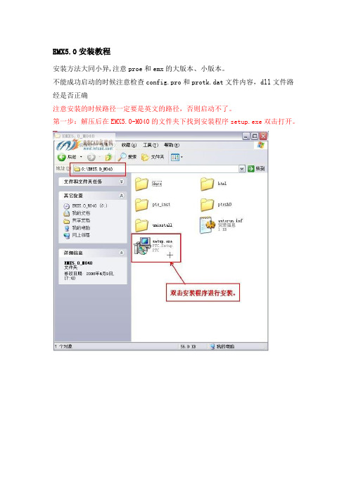
第一步:解压后在EMX5.0-M040的文件夹下找到安装程序setup.exe双击打开。
第二步:进入安装界面,点击emx按钮进行下一步。
第三步:修改安装目录,建议不要安装在系统的c盘,最好是安装在ptc阮晋安安装目录下的同一文件夹里然后《点击安装》。
第四步:等待安装、、、、、、
第五步:安装完成,退出。
第六步:打开安装文件,找到文件emx5.0-wf4.dll5.03.0和shc50-wf4.dll5.05.0文件进行复制。
第七步:将复制出来的文件放到,安装目录下的i486-nt文件夹下。
第八步:复制文件protk-wf4.dat文件。
第九步:把文件粘贴到安装目录下的text文件夹下并用记事本打开,对如下图示的路径进行修改,修改的方法见图片,修改后注意保存。
第十步:复制config.pro和config.win文件
第十一步:把文件config.pro和config.win文件粘贴到proe4.0安装目录下的text文件夹下
第十二步:用记事本打开刚粘贴过来的config.pro文件,将最后一行的路径修改成emx5.0的text文件夹中的protk-wf4.dat的路径,修改后保存。
第十三步:启动proe图标,安装成功!!。
VMware_ESX4 安装教程
VMware ESX4.0详细安装手册注:ESX4.0要求最低服务器硬件配置处理器:两个1500MHz 64位AMD Opteron、Intel Xeon或Intel Nehalem x86处理器内存:RAM最小为2GB、最大为512GB网络连接:一个以太网控制器磁盘存储:基本SCSI适配器、光纤通道适配器或内部RAID控制器目前,不支持在IDE/ATA 驱动器或RAID 中存储虚拟机。
ESX4.0支持以下四种安装源:•指定CD-ROM/DVD 或USB 介质。
您可以选择除可能要用于ESX 安装DVD 的CD-ROM/DVD 驱动器以外的CD-ROM/DVD 驱动器。
•指定网络文件系统服务器,即NFS 服务器,及目录路径。
•指定HTTP 或HTTPS URL。
•指定文件服务器位置,即FTP 位置。
在此实例中使用光盘介质进行安装,将ESX4.0安装光盘放在服务器光驱内,选择从光驱启动,弹出下图由于要使用图形模式,所以按Enter 键。
系统将调用ESX 4.0 安装程序,并滚动显示一系列安装消息。
(如果1 分钟之内未按任何键,将在图形模式下安装。
)此为欢迎使用屏幕。
此时图形安装开始。
单击[Next(下一步)] 继续安装。
我们将选中[I accept the terms of the license agreement(我接受许可协议条款)] 选项,然后单击[Next (下一步)] 继续。
此时出现的是[End User License Agreement(最终用户许可协议)] 页面。
您必须接受该许可协议,否则无法安装该产品。
请在接受此最终用户许可协议之前仔细阅读协议。
在此选择键盘类型,单击[Next下一步]在此实例中我们将选择[No(否)],然后单击[Next(下一步)]。
在此安装进程将加载您的硬件所需要的驱动程序。
如果系统需要自定义驱动程序,您可在此处选择[Yes (是)] 并单击[Add(添加)] 按钮,指定这些驱动程序。
citrix4安装配置实践全程
citrix4.0安装配置实践全程实践环境介绍:网络接入:电信10M光纤 1个固定IP (多种网络服务应用使用)服务器硬件:IBM X3650Xeon EM64T 5130 Dualcore 2.00GHz/1x4MB, 1333MHz FSB, 2-SMP, 4*1GB PC2-5300 DDR2 ECC, 3.5"HS 3* 146GB 10K SAS HDD, 2*Giga Ethernet, Light Path, CD-RW/DVD Combo, 2U ,HS 2*835W Power,Raid0/1/10,导轨/8k阵列卡RAID5操作系统:Windows Server 2003 Standard Edition R2Citrix版本:MetaFrame Presentation Server 4.0 For Windows Server 2003防护软件:诺顿9.0企业版输入法:万能输入法5.6.26 (选择安装内置版本万能五笔)打印机:EPSON LQ 1600K及其他相临型号用户数量:40-60,分布在全国,重点是电信ADSL及铁通ADSL用户;1、citirx简单介绍:(这里不作太多介绍,只发表自己看法;更详细的介绍请参考官方站或其他合作联盟;)a. 将C/S架构的ERP等应用客户端在不改变任何系统架构的基础上,通过Citrix集中运算的模式实现远程应用,以达到集中式管理、保护原有投资、减低总体维护成本目的;b. ICA协议(Citrix的特有协议)它优化了屏幕图像变化数据以及鼠标键盘的操作指令,使客户端和服务器间的数据传送量变得更少;即使是在低带宽的情况下也可以顺利的使用。
c. 支持在多种服务器系统平台部署、支持多种客户端设备(如部分特定智能手机)和客户端操作系统(Linux、MAC OS等),从而真正实现了跨平台应用;d. 可以使用多种网络协议,多种连接方式包含无线;并支持多种安全传输。
PROE4.0外挂中文版EMX4.1和EMX5.6的方法

栢图模具数控培训PRO/E4.0外挂中文版EMX4.1和EMX5.6的方法栢图模具Pro/E培训的学生都会问我这样的一个问题:在Pro/E上外挂中文版的EMX4.1或EMX5.6的方法是什么?针对这个问题,我现在给大家介绍一下在Pro/E上挂中文版EMX4.1和EMX5.6的方法。
PROE4.0挂EMX4.1的安装方法1、打开我的电脑——属性——高级—环境变量—新建系统变量lang=chs2、安装文件,安装语言选择中文,目录要英文的,路径简单点比如:D:\PTC\EMX4.13、到安装目录里的test 文件夹下找到protk.dat 用记事本打开,看下路径是否对比如:exec_file D:\PTC\EMX4.1/$PRO_MACHINE_TYPE/emx41.dll text_dir D:\PTC\EMX4.1然后在end 上面增加一句unicode_encoding false 这一步最重要4、也是在test文件夹下用记事本打开config.pro 看下里面最后一行的路径是否和你自己的安装路径一样,否则该掉。
比如PROTKDAT D:\PTC\EMX4.1/text/protk.dat5、最后把安装目录里的test文件夹下的config.pro和config.win复制到你proe4.0的安装目录里的test 文件夹里就可以了比如:D:\PTC\proewildfire 4.0\text 具体看自己的安装路径6、重新启动计算机,打开proe4.0 你就看到了EMX4.1 了。
最好在第一步之后重新启动计算机,接下来按照步骤!!!PROE4.0挂EMX5.6安装方法1、确保下载的EMX4.0安装文件放在全英文的目录内2、按照正常安装,此时需要注意一下,安装时在language(语言)选项下将简体中文选上就可以了3、打开EMX5.0安装目录(不是安装文件)里的I486_NT文件夹,看清楚里面有2个文件,emx50_wf4.dll、shc50_wf4.dll ,有的话就不用管,若没有复制进去4、用记事本打开EMX5.0\TEXT文件夹里的protk.dat文件,确认一下下面2个路径是否正确,不正确就修改exec_file d:\ptc\emx5.0\i486_nt\emx50_wf4.dlltext_dir d:\ptc\emx5.0\text将路径改为刚安装的EMX5.0对应的目录,否则以后启动会提示找不到文件,EMX就会加载失败.5、把D:\ptc\emx5.0\text下的"config.pro以及config.win"这2个文件复制到"D:\ptc\proeWildfire 4.0\text"(具体看个人的安装目录);6、把刚才复制过来的config.pro用记事本打开,修改最后一行,把PROTKDAT D:\ptc\emx5.0\text\protk.dat改成PROTKDAT D:\ptc\emx5.0\text\protk_wf4.dat(不一定是D:/ptc,具体看个人的安装目录)7、最后看下D:\ptc\emx5.0\text 把里面的protk.dat 改成protk_wf4.dat若就是protk_wf4.dat 就不用改了8、启动proe4.0 OK更多培训教程,请参考:。
raritan emx 快速安装指南 (中文)说明书
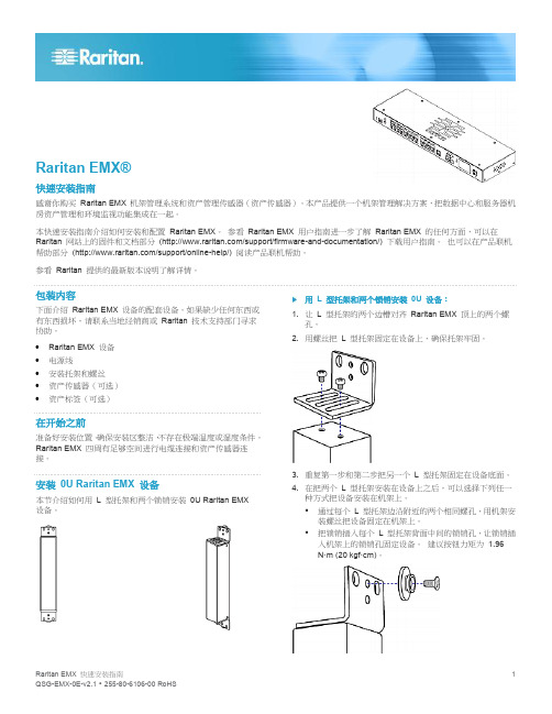
Raritan EMX®快速安装指南感谢你购买Raritan EMX 机架管理系统和资产管理传感器(资产传感器)。
本产品提供一个机架管理解决方案,把数据中心和服务器机房资产管理和环境监视功能集成在一起。
本快速安装指南介绍如何安装和配置Raritan EMX。
参看Raritan EMX 用户指南进一步了解Raritan EMX 的任何方面,可以在Raritan 网站上的固件和文档部分(/support/firmware-and-documentation/) 下载用户指南。
也可以在产品联机帮助部分(/support/online-help/) 阅读产品联机帮助。
参看Raritan 提供的最新版本说明了解详情。
包装内容下面介绍Raritan EMX 设备的配套设备。
如果缺少任何东西或有东西损坏,请联系当地经销商或Raritan 技术支持部门寻求协助。
∙Raritan EMX 设备∙电源线∙安装托架和螺丝∙资产传感器(可选)∙资产标签(可选)在开始之前准备好安装位置。
确保安装区整洁,不存在极端温度或湿度条件。
Raritan EMX 四周有足够空间进行电缆连接和资产传感器连接。
安装0U Raritan EMX 设备本节介绍如何用L 型托架和两个锁销安装0U Raritan EMX设备。
用L 型托架和两个锁销安装0U 设备:1. 让L 型托架的两个边槽对齐Raritan EMX 顶上的两个螺孔。
2. 用螺丝把L 型托架固定在设备上,确保托架牢固。
3. 重复第一步和第二步把另一个L 型托架固定在设备底面。
4. 在把两个L 型托架安装在设备上之后,可以选择下列任一种方式把设备安装在机架上。
▪通过每个L 型托架边沿附近的两个相同螺孔,用机架安装螺丝把设备固定在机架上。
▪把锁销插入每个L 型托架背面中间的锁销孔,让锁销插入机架上的锁销孔固定设备。
建议按钮力矩为 1.96N·m (20 kgf·cm)。
EMX安装方法

LJ工作室制作
祝你工作愉快!^_^
软件类型 Industry
通过提供远远不止一个零件库的功能,Pro/ENGINEER 模架设计专家软件包优化了过程。 它设计为自动执行重复任务,并能获取可在后续设计中重用的内部设计知识。 并且,由于该软件是一种“智能”模具装配和创建详图工具,因此,它产生的 3D 实体模型将随着设计零件的更改而自动更新。 因此,不必过于担心最后一刻的设计变更。
Pro/ENGINEER EMX中的模具设计功能可以让设计人员:
轻松设计、定制和细化模架部件和组件
自动完成诸如余隙切口、螺纹孔、组件安装、顶杆修饰等工作
由于组件和部件可以被自动放置在模架中,所以在自动放置之前,设计人员可以轻松地实时选择和预览3D组件和部件
可以从15个以上的模架和组件供应商预先定制组件和部件,因此没有必要建立模型库
1.拷贝emx4.1到pro/e的安装目录下面,比如C:\proe2001\emx4.1.
2.打开pro/e安装目录\emx4.1\text下的protk.dat进行编辑,设置你的emx安装路径
比如:
exec_file C:\proe2001\emx4.1\i486_nt\emx4.1.dll
运行环境 Win9x/WinNT/Win2000/WinXP
EMX安装教程范文

EMX安装教程范文EMX是一种辅助设计和建模软件,广泛用于电子器件的EDA(电子设计自动化)领域。
安装EMX软件前,需要检查计算机硬件和操作系统的配置是否满足要求,并准备好软件安装文件。
第二步:运行安装文件双击EMX安装文件,打开安装向导。
按照向导提示,点击“下一步”按钮进行安装。
第三步:接受许可协议阅读软件许可协议,并选择“接受”以继续安装。
如果不同意许可协议,则不能安装EMX软件。
第四步:选择安装目录选择EMX软件的安装目录。
通常情况下,将软件安装在默认目录中即可。
如果想更改安装目录,点击“浏览”按钮选择所需目录。
第五步:选择启动菜单文件夹选择EMX软件将显示在计算机启动菜单中的文件夹。
通常情况下,选择默认文件夹即可。
如果想更改文件夹名称,可以手动输入所需名称。
第六步:选择产品功能根据需要选择EMX软件的产品功能。
根据不同的版本,功能选项可能会有所不同。
勾选所需的功能,并点击“下一步”按钮。
第七步:选择附加组件根据需要选择附加组件。
这些组件可以增强软件的功能和性能。
勾选所需的组件,并点击“下一步”按钮。
第八步:选择开始菜单快捷方式选择EMX软件将显示在计算机开始菜单中的快捷方式。
通常情况下,选择默认快捷方式即可。
如果想更改快捷方式名称,可以手动输入所需名称。
第九步:选择桌面快捷方式选择EMX软件将在桌面上创建一个快捷方式。
通常情况下,选择默认选项即可。
如果不想在桌面上创建快捷方式,可以取消勾选。
第十步:确认安装设置在最后一页中,确认所选择的安装设置,并点击“安装”按钮开始安装。
第十一步:等待安装完成等待EMX软件的安装过程完成。
这可能需要一些时间,取决于计算机的性能和安装文件的大小。
第十二步:启动EMX软件安装完成后,点击“完成”按钮退出安装向导。
然后,在计算机的开始菜单中找到EMX软件的快捷方式,并点击启动。
第十三步:激活EMX软件根据EMX软件提供的激活方式,完成软件的激活流程。
通常需要输入激活码或进行在线验证。
EMX4.0的详细安装的说明
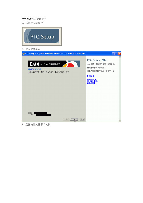
PTC EMX4.0安装说明1.先运行安装程序
2.进入安装界面
3.选择所有元件和子元件
4.点击是开始安装
5.点击是完成安装
6.下面进行配置,进入到EMX的安装目录,然后打开TXET文件夹,选择如图所示的两个文件
7.将以上两个文件复制到EMX的bin目录下
8.然后如图创建快捷方式
点选浏览找到EMX安装目录下bin\config.pro ,如图
点击下一步,出现如下图对话框
将图示中confid.pro改为EMX4.0,然后点击完成快捷方式就建立了。
9.然后对快捷方式的属性进行修改,目标为PRO/E的安装目录\bin\proewildfire.psf,起始位置为刚才复制的那两个文件的目录。
10.点击刚才创建的快捷方式进入EMX,
11.这就是EMX的操作界面
12.安装全部完成。
PTC EMX 4.0安装方法
PTC EMX 4.0安装方法安装方式:如果是BIN格式的文件,请安装Alcohol 120%这个虚拟工具.安装好后在虚拟光盘符上点右键-->载入镜像-->打开-->找到文件(文件类型选,*.*所有文件),找到镜像文件即可.安装前你得先安装Pro/e这个软件Pro/ENGINEER 2001 or WILDFIRE or WILDFIRE2.0 ,并而这些软件的授权文件能使用.1.拷贝emx4.0到pro/e的安装目录下面,比如C:\proe2001\emx40.2.打开pro/e安装目录\emx40\text下的protk.dat进行编辑,设置你的emx安装路径比如:exec_file C:\proe2001\emx40\i486_nt\emx40.dlltext_dir C:\proe2001\emx40\text3.打开pro/e安装目录\emx40\text下的config.pro进行编辑,修改配置选项的最后一行"PROTKDAT"为你的安装目录,比如:C:\proe2001\emx40\text\protk.dat4.拷贝config.pro and the config.win到你的启动目录,比如:C:\proe2001 \text完成启动PRO/E。
安装说明1.拷贝emx4.0到pro/e的安装目录下面,比如C:\proe2001\emx40.2.打开pro/e安装目录\emx40\text下的protk.dat进行编辑,设置你的emx安装路径比如:exec_file C:\proe2001\emx40\i486_nt\emx40.dlltext_dir C:\proe2001\emx40\text3.打开pro/e安装目录\emx40\text下的config.pro进行编辑,修改配置选项的最后一行"PROTKDAT"为你的安装目录,比如:C:\proe2001\emx40\text\protk.dat4.拷贝config.pro and the config.win到你的启动目录,比如:C:\proe2001\text。
VMware ESX Server 4.0安装
VMware ESX Server 4.0安装一,安装前的准备;1,确认你的硬件设备支持虚拟化。
2,确认启用了硬件服务器的虚拟化功能。
例如CPU的VT功能。
3,进行合理网络拓扑规划。
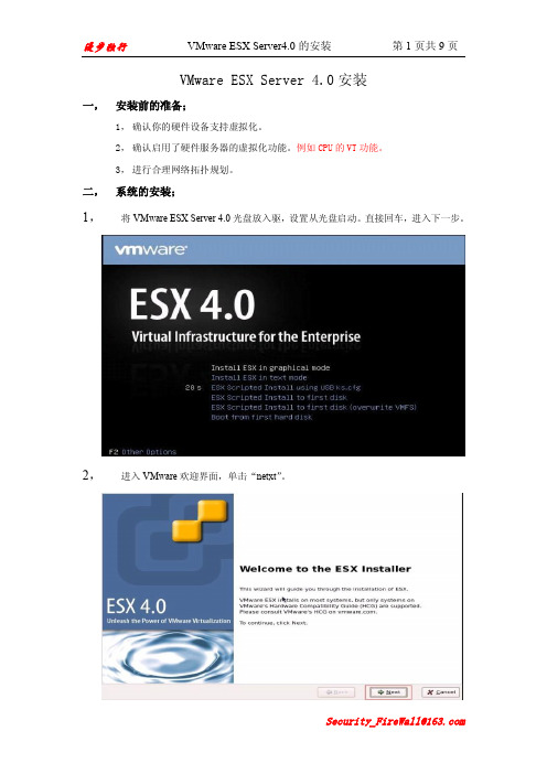
二,系统的安装;1,将VMware ESX Server 4.0光盘放入驱,设置从光盘启动。
直接回车,进入下一步。
2,进入VMware欢迎界面,单击“netxt”。
4,选择键盘语言类型,单击“netxt”。
加载定制硬件驱动,选择“是”,进入下一步。
6,开始加载VMware ESX Server所需的默认驱动,单击“next”。
“netxt”。
8,配置网络接口,如需要加入vlan,则勾先加入vlan并输入要加入的vlan ID,然后单击“next”。
自动获取,多个ESX Server则必须在同一个域内。
10,选择安装类型,如果只有单个硬盘,可以选择(Standard setup)默认分区,如果有多个硬盘,则选择(Advancedsetup)自定义分区。
然后单击“next”。
11,系统自动检测到的存储设备,选择要将ESX Server安装到的存储设备,单击“next”弹出警告信息,提示选中的存储设备里的数据将被清除,选择“是”。
12,设置时区,然后单击“next”。
13,手动配置系统日期及时间,也可以输入NTP时间同步服务器地址自动同步。
然后单击“next”。
14,配置根用户(root)密码,单击“next”。
15,确认安装配置,然后单击“next”进行安装。
16,安装完成,单击“netxt”。
17,提示安装完成,单击“Finish”重新引导系统。
VideoJet X10 X20 X40 服务器通道视频服务器快速安装指南说明书

VideoJet X10/X20/X40 Servidor de canal de vídeoes Guía de instalación rápidaVideoJet X10/X20/X40Información general | es 2Bosch Security Systems Guía de instalación rápida F.01U.033.683 | V3.5 | 2009.011Información generalLas instrucciones de esta "Guía de instalación rápida" hacenreferencia a las unidades VideoJet X10, VideoJet X20 yVideoJet X40. En el título aparece el modelo VideoJet X40. Enlos dibujos se muestra la versión VideoJet X40 como ejemplopara todas las versiones.Encontrará información más detallada en la ayuda en líneacompleta del dispositivo correspondiente.i ¡NOTA!Deberá familiarizarse siempre con las medidas de seguridadnecesarias en el capítulo correspondiente del manual delusuario (consulte el CD-ROM proporcionado). Encontrarátambién detalles importantes sobre la instalación y elfuncionamiento de la unidad en dicho manual. Lasinstrucciones de la "Guía de instalación rápida" sólo muestranla instalación rápida del modelo VideoJet X10, VideoJet X20 oVideoJet X40, pero no sustituyen el manual del usuariocompleto.3es | Contenido entregado VideoJet X10/X20/X402Contenido entregado–Servidor de canal de vídeo VideoJet X10, VideoJet X20 oVideoJet X40–Plantilla de perforación–Cuatro conectores–CD del producto–Guía de instalación rápidaF.01U.033.683 | V3.5 | 2009.01Guía de instalación rápida Bosch Security SystemsVideoJet X10/X20/X40Desembale el equipo | es4 3Desembale el equipo–Compruebe que el contenido del envío está completo yque no hay elementos en mal estado.–Bosch Security Systems comprobará la unidad si detecta algún daño.Bosch Security Systems Guía de instalación rápida F.01U.033.683 | V3.5 | 2009.015es | Conexión VideoJet X10/X20/X40F.01U.033.683 | V3.5 | 2009.01Guía de instalación rápida Bosch Security Systems4Conexión 4.1–VideoJet X10: conecte la cámara al conector Video In .–VideoJet X20: conecte una cámara al conector Video In 1 y la otra al conector Video In 2.–VideoJet X40: conecte una cámara a cada una de lascuatro entradas de vídeo, desde el conector Video In 1 alconector Video In 4.VideoJet X10/X20/X40Conexión | es6 4.2Conexión de los componentes de audio–Utilice las tomas Audio In y Audio Out para realizar lasconexiones de las líneas de audio.Bosch Security Systems Guía de instalación rápida F.01U.033.683 | V3.5 | 2009.017es | Conexión VideoJet X10/X20/X40F.01U.033.683 | V3.5 | 2009.01Guía de instalación rápida Bosch Security Systems4.3Conexión de los conmutadores de alarma y las conexiones con relé–Conecte los conmutadores de alarma a los terminales correspondientes.–Conecte las conexiones con relé a los terminales correspondientes.VideoJet X10/X20/X40Conexión | es 8Bosch Security Systems Guía de instalación rápida F.01U.033.683 | V3.5 | 2009.014.4–Si es necesario, introduzca un módulo SFP en la toma SFP .9es | Conexión VideoJet X10/X20/X40F.01U.033.683 | V3.5 | 2009.01Guía de instalación rápida Bosch Security Systems4.5–Conecte la unidad a la red mediante el conector ETH 1.–Si es necesario, realice una conexión de red redundante oconecte un sistema iSCSI RAID utilizando un conectorETH 2.–Conecte las líneas de alimentación a los terminales + y –.–Conecte la unidad de alimentación a la toma de corriente.Nota:Las unidades de alimentación no se incluyen en el contenido dela entrega. Puede solicitar distintos tipos de unidades dealimentación a Bosch Security Systems.VideoJet X10/X20/X40Configuración | es 10Bosch Security Systems Guía de instalación rápida F.01U.033.683 | V3.5 | 2009.015Configuración 5.1Configure la dirección IP–Instale el programa Configuration Manager desde el CD-ROM proporcionado. Si el CD-ROM no se inicia de formaautomática, haga doble clic en el archivo index.htm .–Inicie Configuration Manager cuando se haya completadola instalación. Se realiza un escaneo de la red paradetectar automáticamente dispositivos compatibles.–Cuando aparezca el dispositivo VideoJet X, haga clic en la entrada y en la ficha Network del marco derecho.–Introduzca la dirección IP que desee (p. ej., 192.168.0.40)en el campo Unit IP address y haga clic en el botón Set enla parte inferior derecha. La nueva dirección IP será válidadespués de reiniciar la unidad.11es | Configuración VideoJet X10/X20/X40F.01U.033.683 | V3.5 | 2009.01Guía de instalación rápida Bosch Security Systems5.2Prueba de la configuración–Inicie el explorador Web e introduzca la dirección IP de launidad (p. ej., http://192.168.0.40) para comprobar que launidad está conectada correctamente a la red.Nota:Establezca la tarjeta gráfica del ordenador en una profundidadde color de 16 o 32 bits. De lo contrario, el ordenador no podrámostrar imágenes de vídeo.–Utilice los enlaces de la parte superior de las páginas Web para desplazarse.Bosch Security SystemsRobert-Koch-Straße 100D-85521 OttobrunnGermanyTelefon089 6290-0Fax089 6290-1020 © Bosch Security Systems, 2009。
proe5.0同时挂emx4.1和emx5.0
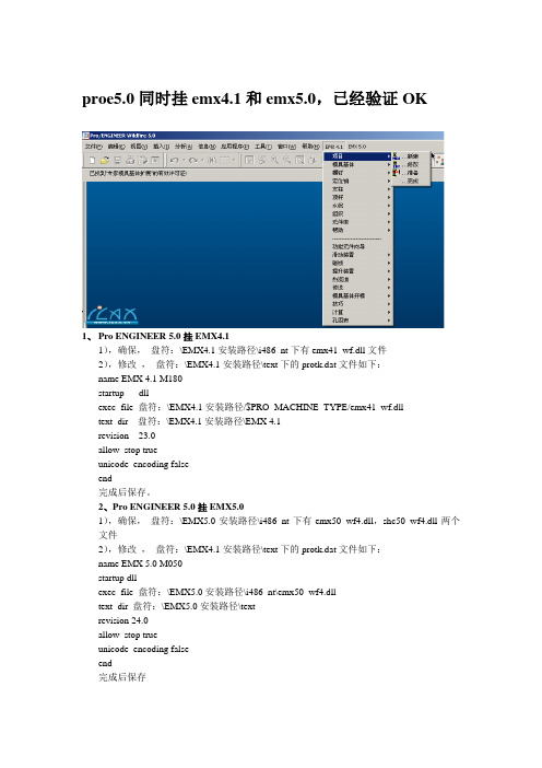
proe5.0同时挂emx4.1和emx5.0,已经验证OK1、Pro ENGINEER 5.0挂EMX4.11),确保,盘符:\EMX4.1安装路径\i486_nt下有emx41_wf.dll文件2),修改,盘符:\EMX4.1安装路径\text下的protk.dat文件如下:name EMX 4.1 M180startup dllexec_file 盘符:\EMX4.1安装路径/$PRO_MACHINE_TYPE/emx41_wf.dlltext_dir 盘符:\EMX4.1安装路径\EMX 4.1revision 23.0allow_stop trueunicode_encoding falseend完成后保存。
2、Pro ENGINEER 5.0挂EMX5.01),确保,盘符:\EMX5.0安装路径\i486_nt下有emx50_wf4.dll,shc50_wf4.dll两个文件2),修改,盘符:\EMX4.1安装路径\text下的protk.dat文件如下:name EMX 5.0 M050startup dllexec_file 盘符:\EMX5.0安装路径\i486_nt\emx50_wf4.dlltext_dir 盘符:\EMX5.0安装路径\textrevision 24.0allow_stop trueunicode_encoding falseend完成后保存3、在你的Pro ENGINEER 5.0的configro中加入以下内容,打开Pro ENGINEER 5.0就可以使用EMX4.1和EMX5.0.mapkey buwprojna @MAPKEY_NAMEDefine new project;\mapkey(continued) @MAPKEY_LABELDefine new project;~ Activate `main_dlg_cur` `CreateProject`;mapkey buwprodatanzaend @MAPKEY_NAMEModify project;\mapkey(continued) @MAPKEY_LABELModify project;~ Activate `main_dlg_cur` `EditProject`;mapkey buwproaufb @MAPKEY_NAMEPrepare project;@MAPKEY_LABELPrepare project;\mapkey(continued) ~ Activate `main_dlg_cur` `PrepareProject`;mapkey buwwezedef @MAPKEY_NAMEDefine Moldbase Assembly;\mapkey(continued) @MAPKEY_LABELDefine Moldbase Assembly;\mapkey(continued) ~ Activate `main_dlg_cur` `MoldbaseDefinition`;mapkey buwcomp @MAPKEY_NAMEAssemble/Disassemble Components;\mapkey(continued) @MAPKEY_LABELAssemble/Disassemble Components;\mapkey(continued) ~ Activate `main_dlg_cur` `ComponentStatus`;mapkey buwcrequ @MAPKEY_NAMEDefine equipment on existing point;\mapkey(continued) @MAPKEY_LABELDefine equipment on existing point;\mapkey(continued) ~ Activate `main_dlg_cur` `DefineEquipment`;mapkey buwmodequi @MAPKEY_NAMERedefine equipment;\mapkey(continued) @MAPKEY_LABELRedefine equipment;\mapkey(continued) ~ Activate `main_dlg_cur` `RedefineEquipment`;mapkey buwdelequi @MAPKEY_NAMEDelete equipment;@MAPKEY_LABELDelete equipment;\mapkey(continued) ~ Activate `main_dlg_cur` `DeleteEquipment`;mapkey buwcreguide @MAPKEY_NAMEDefine guide on existing point;\mapkey(continued) @MAPKEY_LABELDefine guide on existing point;\mapkey(continued) ~ Activate `main_dlg_cur` `DefineGuide`;mapkey buwmodguide @MAPKEY_NAMERedefine guide;@MAPKEY_LABELRedefine guide;\mapkey(continued) ~ Activate `main_dlg_cur` `RedefineGuide`;mapkey buwdelguide @MAPKEY_NAMEDelete guide;@MAPKEY_LABELDelete guide;\ mapkey(continued) ~ Activate `main_dlg_cur` `DeleteGuide`;mapkey buwspavpk @MAPKEY_NAMEDefine screw on existing point;\mapkey(continued) @MAPKEY_LABELDefine screw on existing point;\mapkey(continued) ~ Activate `main_dlg_cur` `DefineScrewExisting`;mapkey buwcrscrmse @MAPKEY_NAMEDefine screw on mousepoint;\mapkey(continued) @MAPKEY_LABELDefine screw on mousepoint;\mapkey(continued) ~ Activate `main_dlg_cur` `DefineScrewMouse`;mapkey buwscrred @MAPKEY_NAMERedefine screw;@MAPKEY_LABELRedefine screw;\mapkey(continued) ~ Activate `main_dlg_cur` `RedefineScrew`;mapkey buwschrdel @MAPKEY_NAMEDelete screw;@MAPKEY_LABELDelete screw;\mapkey(continued) ~ Activate `main_dlg_cur` `DeleteScrew`;mapkey buwsavp @MAPKEY_NAMEDefine dowel pin on existing point;\mapkey(continued) @MAPKEY_LABELDefine dowel pin on existing point;\mapkey(continued) ~ Activate `main_dlg_cur` `DefinePinExisting`;mapkey buwstmouse @MAPKEY_NAMEDefine dowel pin on mousepoint;\mapkey(continued) @MAPKEY_LABELDefine dowel pin on mousepoint;\mapkey(continued) ~ Activate `main_dlg_cur` `DefinePinMouse`;mapkey buwstred @MAPKEY_NAMERedefine Dowel pin;\mapkey(continued) @MAPKEY_LABELRedefine Dowel pin;~ Activate `main_dlg_cur` `RedefinePin`;mapkey buwstdel @MAPKEY_NAMEDelete dowel pin;@MAPKEY_LABELDelete dowel pin;\mapkey(continued) ~ Activate `main_dlg_cur` `DeletePin`;mapkey buwapavp @MAPKEY_NAMEDefine ejector pin on existing point;\mapkey(continued) @MAPKEY_LABELDefine ejector pin on existing point;\mapkey(continued) ~ Activate `main_dlg_cur` `DefineEjectorExisting`;mapkey buwapampp @MAPKEY_NAMEDefine ejector pin on mousepoint;\mapkey(continued) @MAPKEY_LABELDefine ejector pin on mousepoint;\mapkey(continued) ~ Activate `main_dlg_cur` `DefineEjectorMouse`;mapkey buwausred @MAPKEY_NAMERedefine Ejector pin;\mapkey(continued) @MAPKEY_LABELRedefine Ejector pin;\mapkey(continued) ~ Activate `main_dlg_cur` `RedefineEjector`;mapkey buwausdel @MAPKEY_NAMEDelete ejector pin;\mapkey(continued) @MAPKEY_LABELDelete ejector pin;~ Activate `main_dlg_cur` `DeleteEjector`;mapkey buwkueerz @MAPKEY_NAMECreate cooling bore;\mapkey(continued) @MAPKEY_LABELCreate cooling bore;~ Activate `main_dlg_cur` `DefineCooling`;mapkey buwkuered @MAPKEY_NAMERedefine cooling bore;\mapkey(continued) @MAPKEY_LABELRedefine cooling bore;\mapkey(continued) ~ Activate `main_dlg_cur` `RedefineCooling`;mapkey buwkuetankerz @MAPKEY_NAMECreate CoolingTank;\mapkey(continued) @MAPKEY_LABELRedefine cooling bore;\mapkey(continued) ~ Activate `main_dlg_cur` `DefineCoolingTank`;mapkey buwkuedel @MAPKEY_NAMEDelete cooling bore;\mapkey(continued) @MAPKEY_LABELDelete cooling bore;~ Activate `main_dlg_cur` `DeleteCooling`;mapkey buwspavp @MAPKEY_NAMEDefine support pillar on existing point;\mapkey(continued) @MAPKEY_LABELDefine support pillar on existing point;\mapkey(continued) ~ Activate `main_dlg_cur` `DefineSupportExisting`;mapkey buwspmouse @MAPKEY_NAMEDefine support pillar on mousepoint;\mapkey(continued) @MAPKEY_LABELDefine support pillar on mousepoint;\mapkey(continued) ~ Activate `main_dlg_cur` `DefineSupportMouse`;mapkey buwsupred @MAPKEY_NAMERedefine support pillar;\mapkey(continued) @MAPKEY_LABELRedefine support pillar;\mapkey(continued) ~ Activate `main_dlg_cur` `RedefineSupport`;mapkey buwsdel @MAPKEY_NAMEDelete support pillar;\mapkey(continued) @MAPKEY_LABELDelete support pillar;~ Activate `main_dlg_cur` `DeleteSupport`;mapkey buwvseae @MAPKEY_NAMEChange bom-entry;@MAPKEY_LABELChange bom-entry;\mapkey(continued) ~ Activate `main_dlg_cur` `EditBOMEntry`;mapkey buwbomformat @MAPKEY_NAMEFormat Bill of Materials;\mapkey(continued) @MAPKEY_LABELFormat Bill of Materials;~ Activate `main_dlg_cur` `FormatBOM`;mapkey buwbomcheck @MAPKEY_NAMECheck BOM-Entries;\mapkey(continued) @MAPKEY_LABELCheck BOM-Entries;~ Activate `main_dlg_cur` `CheckBOMEntries`;mapkey buwdeflib @MAPKEY_NAMEPrepare library-component;\mapkey(continued) @MAPKEY_LABELPrepare library-component;\mapkey(continued) ~ Activate `main_dlg_cur` `DefineLibraryComp`;mapkey buwbibasm @MAPKEY_NAMEAssemble library-component;\mapkey(continued) @MAPKEY_LABELAssemble library-component;\mapkey(continued) ~ Activate `main_dlg_cur` `AssembleLibraryComp`;mapkey buwbibredefine @MAPKEY_NAMERedefine library-component;\mapkey(continued) @MAPKEY_LABELRedefine library-component;\mapkey(continued) ~ Activate `main_dlg_cur` `RedefineLibraryComp`;mapkey buw_lib_delete @MAPKEY_NAMEDelete library-component;\mapkey(continued) @MAPKEY_LABELDelete library-component;\mapkey(continued) ~ Activate `main_dlg_cur` `DeleteLibraryComp`;mapkey buwsdae @MAPKEY_NAMEDefine/modify slider;\mapkey(continued) @MAPKEY_LABELDefine/modify slider;~ Activate `main_dlg_cur` `DefineSlider`;mapkey buwdelslider @MAPKEY_NAMEDelete Slider;@MAPKEY_LABELDelete Slider;\ mapkey(continued) ~ Activate `main_dlg_cur` `DeleteSlider`;mapkey buwcreatelifter @MAPKEY_NAMEDefine/Modify Lifter;\mapkey(continued) @MAPKEY_LABELDefine/Modify Lifter;~ Activate `main_dlg_cur` `DefineLifter`;mapkey buwdellifter @MAPKEY_NAMEDelete Lifter;@MAPKEY_LABELDelete Lifter;\ mapkey(continued) ~ Activate `main_dlg_cur` `DeleteLifter`;mapkey buwkliaen @MAPKEY_NAMEDefine latch lock;\mapkey(continued) @MAPKEY_LABELDefine latch lock;~ Activate `main_dlg_cur` `DefineLatch`;mapkey buwdellatch @MAPKEY_NAMEDelete latch lock;\mapkey(continued) @MAPKEY_LABELDelete latch lock;~ Activate `main_dlg_cur` `DeleteLatch`;mapkey buwwzofg @MAPKEY_NAMEDefine moldbase opening;\mapkey(continued) @MAPKEY_LABELDefine moldbase opening;\mapkey(continued) ~ Activate `main_dlg_cur` `DefineSimulation`;mapkey buwwzani @MAPKEY_NAMESimulate moldbase opening;\mapkey(continued) @MAPKEY_LABELSimulate moldbase opening;\mapkey(continued) ~ Activate `main_dlg_cur` `RunSimulation`;mapkey buwsimstop @MAPKEY_NAMEClose moldbase opening mode;\mapkey(continued) @MAPKEY_LABELClose moldbase opening mode;\mapkey(continued) ~ Activate `main_dlg_cur` `QuitSimulation`;mapkey buwbwdb @MAPKEY_NAMECalculate clamping forces;\mapkey(continued) @MAPKEY_LABELCalculate clamping forces;\mapkey(continued) ~ Activate `main_dlg_cur` `CalculateBending`;mapkey buw_createhc @MAPKEY_NAMECreate Holechart;\mapkey(continued) @MAPKEY_LABELCreate Holechart;~ Activate `main_dlg_cur` `CreateHolechart`;mapkey buw_delhc @MAPKEY_NAMEDelete Holech怅rt;@MAPKEY_LABELDelete Holechart;\mapkey(continued) ~ Activate `main_dlg_cur` `DeleteHolechart`;mapkey buw_make_hr @MAPKEY_NAMEDefineHotrunner;@MAPKEY_LABELDefineHotrunner;\mapkey(continued) ~ Activate `main_dlg_cur` `DefineHotrunner`;mapkey buw_delete_hr @MAPKEY_NAMEDeleteHotrunner;\mapkey(continued) @MAPKEY_LABELDeleteHotrunner;~ Activate `main_dlg_cur` `DeleteHotrunner`;mapkey buwtransm_create @MAPKEY_NAMECreate Transmission;\mapkey(continued) @MAPKEY_LABELCreate Transmission;\mapkey(continued) ~ Activate `main_dlg_cur` `DefineTransmission`;mapkey buw_transm_delete @MAPKEY_NAMEDelete Transmission;\mapkey(continued) @MAPKEY_LABELDelete Transmission;\mapkey(continued) ~ Activate `main_dlg_cur` `DeleteTransmission`;;default_ext_ref_scope ALLset_trail_single_step NOnative_kbd_macros NOopen_simplified_rep_by_default NOshow_dim_sign noenable_absolute_accuracy yesaccuracy_lower_bound .0000001protkdat 盘符:\EMX5.0安装路径\text\protk.datprotkdat 盘符:\EMX4.1安装路径\text\protk.datemx41_wf.dll,emx50_wf4.dll,shc50_wf4.dll文件网上有很多地方可以下载得到,最主要是在protk.dat文件中添加allow_stop true ;unicode_encoding false 这两句。
Moxa AirWorks Edition 4.0 快速安装指南说明书

P/N: 1802062220013 *1802062220013*AWK-6222Quick Installation GuideMoxa AirWorksEdition 4.0, October 2016Technical Support Contact Information/supportMoxa Americas:Toll-free: 1-888-669-2872 Tel: 1-714-528-6777 Fax: 1-714-528-6778 Moxa China (Shanghai office): Toll-free: 800-820-5036 Tel: +86-21-5258-9955 Fax: +86-21-5258-5505 Moxa Europe:Tel: +49-89-3 70 03 99-0 Fax: +49-89-3 70 03 99-99 Moxa Asia-Pacific:Tel: +886-2-8919-1230 Fax: +886-2-8919-1231 Moxa India:Tel: +91-80-4172-9088 Fax: +91-80-4132-10452016 Moxa Inc. All rights reserved.Notes for the ReaderNOTE Highlights important information related to this product.Package ChecklistMoxa’s AWK-6222 is shipped with the following items. If any of these items is missing or damaged, please contact your customer service representative for assistance.• 1 AWK-6222• 2 dual-band omni-directional antennas (5/2 dBi, N-type (male),2.4/5 GHz)•Wall-mounting kit (includes 2 supports)•Field-installable power plug•Field-installable RJ45 plug• 2 metal caps to cover RJ45 connectors•Metal cap to cover M12-female DI/O connector• 2 metal caps to cover N-type connectors•Transparent plastic sticks for field-installable plugs •Documentation and software CD•Quick installation guide (printed)•Warranty cardNOTE The items above come with the standard version AWK-6222 The package contents may vary for customized versions. InstallationBefore installing the AWK-6222, make sure that all items in the package checklist are in the box. In addition, you will need access to a notebook computer or PC equipped with an Ethernet port. The AWK-6222 has a default IP address, user name and password that you must use when resetting or connecting to your AWK-6222 device.Default IP address: 192.168.127.253User name: adminPassword: rootPlease read “Chapter 2: Getting Started” in the AWK-6222 User’s Manual for more details about installation and configuration.NOTE To make the change effective, you must save the change and then click Restart → Save and Restart button to apply allchanges.Panel Layout of the AWK-62221.MAIN 1 antenna port.2.MAIN 2 antenna port.3.AUX 1 antenna port.4.AUX 2 antenna port.5.LEDs for PWR, FAULT,STATE, WLAN1, WLAN2,LAN1, and LAN2.6.M12 A-coding connector forPWR1 and PWR2.7.M12 8-pin connector forDI/DO8.10/100BaseT(X) RJ45 Port:LAN1 and LAN29.RS-232 console port.10.Reset button11.Screw holes for wallmounting12.Waterproof vent13.Grounding screw14.Screw holes for DIN-railmountingDimensions (unit = mm)Wall MountingIn most applications, wall mount provides an easier installation. You will find it quite easy to mount AWK-6222 on the wall, as illustrated below. STEP 1:Attach the wall-mounting kit with M4 screws, as shown in the diagram below:STEP 2:Mounting the AWK-6222 on the wall requires 4 screws. Use the AWK-6222 device, with wall-mounting kitattached, as a guide to mark the correct locations of the 4 screws. The heads of the screws should be between 5.5 mm and 8.5 mm in diameter, and theshafts should not be more than 5.0 mm in diameter, asshown in the figure.Do not drive the screws in all the way into the wall—leave a space of about 2 mm to allow room to slide the wall-mounting kit between the wall and the screws.STEP 3:Once the screws are fixed into the wall, insert the four screw heads through the large opening of the keyhole-shaped apertures, and then slide the AWK-6222 downwards, as indicated to the right. Tighten the four screws for added stability.DIN-Rail Mounting (Optional)The DK-DC50131 die-cast metal kit canbe bought separately, and enable easy androbust installation for the AWK-6222. Apair of DK-DC50131s is needed forDIN-rail mounting. To install the DIN-railmounting kits, tightly attach the twoDIN-rail mounting kits on the rear panel ofAWK-6222 with 12 screws (6 screws foreach kit).To InstallSTEP 1:Use the recessed button on the spring-loaded bracket to lock it into position. STEP 2:Insert the top of the DIN rail into the slot just below the upper hook of the DIN-rail mounting kit. Push the AWK-6222 toward the DIN rail until the DIN-rail attachment bracket snaps into place.To ReleaseSTEP 1:Pull out the two spring-loaded brackets from the bottom until they are fixed in the “release” position.STEP 2:Pull the AWK-6222 out and upward.Wiring RequirementsYou should also pay attention to the following items: •Use separate paths to route wiring for power and devices. If power wiring and device wiring paths must cross, make sure the wires are perpendicular at the intersection point.NOTE Do not run signal or communications wiring and power wiring in the same wire conduit. To avoid interference, wires with different signal characteristics should be routed separately.•You can use the type of signal transmitted through a wire todetermine which wires should be kept separate. The rule of thumb is that wiring with similar electrical characteristics can be bundled together.• Keep input wiring and output wiring separate.• It is strongly advised that you label wiring to all devices in the system for easy identification.Grounding Moxa AWK-6222Grounding and wire routing help limit the effects of noise due toelectromagnetic interference (EMI). Run the ground connection from the ground screw to the grounding surface prior to connecting devices.Installations with Unstable Power InputsThere are cases where the device has to be wired to the same power source as other equipment. In such cases if equipment such as motors that are connected in the circuit draw a large amount of current during operation, the transient voltage drop could potentially cause the AWK to become unstable. Installing a DC/DC power isolator between the two equipment is recommended to isolate the transient effect in and to ensure a stable power input for the AWK.Installations with Cable Extended Antennas for Outdoor ApplicationsIf the antenna or the AWK device is installed outdoors or in an open-air setting, proper lightning protection is required to prevent direct lightning strikes on the AWK device. In order to prevent coupling currents from nearby lightning strikes, a lightning arrester should be installed as part of your antenna system. Ground the device, antenna, as well as the arrester properly to provide maximum outdoor protection for the device.Arrester Accessories • SA-NMNF-01: Surge arrester, N-type (male) to N-type (female) •SA-NFNF-01: Surge arrester, N-type (female) to N-type (female)Wiring the Redundant Power InputsThe AWK-6222 must be connected to a power-over-Ethernet (PoE) IEEE 802.3af compliant power source or an IEC60950 compliant limited power source. When AWK-6222 is powered via DC power, the M12 A-coding connector on the bottom panel is used for the AWK-6222’s two redundant inputs. The pin assignment is shown below:Pin Power Input1 V1+ 2V2+ 3V1- 4 V2- 5GNDWiring the Digital Inputs and Relay Contact (Digital Output)The AWK-6222 has two sets of digital input—DI1 and DI2. Each DIcomprises two contacts of the 8-pin M12 connector on the AWK-6222’s bottom panel. These two digital inputs can be connected to digital-output-enabled sensors for on-site status monitoring.The AWK-6222 also has one relay output, which consists of the twocontacts. These relay contacts are used to detect user-configured events. The two wires attached to the relay contacts form an open circuit when a user-configured event is triggered. If a user-configured event does not occur, the relay circuit will be closed.A field-installable plug, M12A-8PMM-IP68, is recommended for connecting the AWK-6222’s DIs and relay.Communication Connections10/100BaseT(X) Ethernet Port ConnectionThe 10/100BaseT(X) ports located on the AWK-6222’s bottom panel are used to connect to Ethernet-enabled devices.The pinouts for both MDI (NIC-type) ports and MDI-X (HUB/Switch-type) ports are shown below.MDI Port Pinouts MDI-X Port Pinouts8-pin RJ45Pin Signal 1 Tx+ 2 Tx- 3 Rx+ 6 Rx-Pin Signal 1 Rx+ 2 Rx- 3 Tx+ 6 Tx-Pin Signal 1 Relay 2 3 DI1 I1 4 DI1 COM_1 5 DI2 I2 6 DI2 COM_2 7 Reserved8RS-232 ConnectionThe AWK-6222 has one RS-232 (8-pin RJ45) console port located on the bottom panel. Use either an RJ45-to-DB9 or RJ45-to-DB25 cable to connect the Moxa AWK-6222’s console port to your PC’s COM port. You may then use a console terminal program to access the AWK-6222 for console configuration.Console Pinouts for 10-pin or 8-pin RJ45 10-PinDescription8-Pin 1 – – 2 DSR 1 3 RTS24 GND 35 TxD 46 RxD 57 DCD 68 CTS 79 DTR 8 10––NOTE1. The pin numbers for male DB9 and DB25 male connectors, and hole numbers for DB9 and DB25 female connectors, are labeled on the connector strip. However, the numbers are typically quite small, so you may need to use a magnifying glass to see the numbers clearly.2. The pin numbers for both 8-pin and 10-pin RJ45 connectors(and ports) are typically not labeled on the connectors (or ports). Refer to the pinout diagram above for details.Waterproof RJ45 Plug (Optional)Dimensions (unit: mm)InstallationSTEP 1:Attach the gasket ① to thehousing ③STEP 2:Insert the cable (ex. CAT5e) through the clamp ring ④, screw nut ②, seal ⑤ and housing ③, as follows:STEP 3:Crimp the modular RJ plug to the cable. Note that the use of a snagless cover shield or a strain-relief boot is not recommended here. Then, assemble the seals and the housing (③ and ⑤).STEP 4:Tightly screw the clamp ring ④ tothe housing and check to make surethat the plug is securely fastened.(NOTE: For a tighter connection,you can connect the RJ-45 plug tothe AWK-6222 before STEP 4.)LED IndicatorsThe front panel of the Moxa AWK-6222 contains several LED indicators. The function of each LED is described in the table below:LED Color State DescriptionPWR Green OnPower is being supplied (from powerinput 1 or 2, or PoE)Off Power is not being supplied.FAULT RedOnThe relay output is triggered by theevent.Blinking(slow at1-secondintervals)Cannot get an IP address from theDHCP server.Blinking(fast at0.5-secondintervals)IP address conflict.Off No error condition exists.STATE Green/RedGreenSystem startup is complete and thesystem is in operation.GreenBlinking(at 1-secondintervals)The device has been located by theWireless Search Utility.Red System is booting up.WLAN 1 Green/Amber Green OnWLAN is functioning in client/slavemode.GreenBlinkingWLAN’s is transmitting data inclient/slave mode.Amber OnWLAN is functioning inAP/bridge/master mode. AmberBlinkingWLAN’s is transmitting data inAP/bridge/master mode.OffWLAN is not in use or not workingproperly.WLAN 2 Green/Amber Green OnWLAN is functioning in client/slavemode.GreenBlinkingWLAN’s is transmitting data inclient/slave mode.Amber OnWLAN is functioning inAP/bridge/master mode. AmberBlinkingWLAN’s is transmitting data inAP/bridge/master mode.OffWLAN is not in use or not workingproperly.LAN 1 Yellow/Green Yellow On LAN port’s 10 Mbps link is active. YellowBlinkingData is being transmitted at 10 Mbps. Yellow Off LAN port’s 10 Mbps link is inactive. Green On LAN port’s 100 Mbps link is active. GreenBlinkingData is being transmitted at 100Mbps.Green Off LAN port’s 100 Mbps link is inactive.LAN 2 Yellow/Green Yellow On LAN port’s 10 Mbps link is active. YellowBlinkingData is being transmitted at 10 Mbps. Yellow Off LAN port’s 10 Mbps link is inactive. Green On LAN port’s 100 Mbps link is active. GreenBlinkingData is being transmitted at 100Mbps.Green Off LAN port’s 100 Mbps link is inactive.SpecificationsWLANStandards IEEE 802.11a/b/g for Wireless LANIEEE 802.11i for Wireless SecurityIEEE 802.3 for 10BaseT(X)IEEE 802.3u for 100BaseT(X)IEEE 802.3af for Power-over-EthernetIEEE 802.1D for Spanning Tree Protocol(STP)IEEE 802.1w for Rapid STPIEEE 802.1Q for VLANSpread Spectrum and Modulation (Typical) • DSSS with DBPSK, DQPSK, CCK• OFDM with BPSK, QPSK, 16QAM, 64QAM • 802.11b: CCK @ 11/5.5 Mbps, DQPSK @ 2 Mbps, DBPSK @ 11 Mbps• 802.11a/g: 64QAM @ 54/48 Mbps, 16QAM @ 36/24 Mbps, QPSK @ 18/12 Mbps, BPSK @ 9/6 MbpsOperating Channels (central frequency) US:2.412 to 2.462 GHz (11 channels)5.18 to 5.24 GHz (4 channels)EU:2.412 to 2.472 GHz (13 channels)5.18 to 5.24 GHz (4 channels)JP:2.412 to 2.472 GHz (13 channels, OFDM) 2.412 to 2.484 GHz (14 channels, DSSS) 5.18 to 5.24 GHz (4 channels for W52)Security • SSID broadcast enable/disable• Firewall for MAC/IP/Protocol/Port-basedfiltering• 64-bit and 128-bit WEP encryption, WPA/WPA2 Personal and Enterprise (IEEE 802.1X/RADIUS, TKIP, and AES)Protocol Support General Protocols:Proxy ARP, DNS, HTTP, HTTPS, IP, ICMP, SNTP,TCP, UDP, RADIUS, SNMP, PPPoE, DHCPAP-only Protocols:ARP, BOOTP, DHCP, STP/RSTP (IEEE 802.1D/w) Transmission Rates 802.11b: 1, 2, 5.5, 11 Mbps802.11a/g: 6, 9, 12, 18, 24, 36, 48, 54 Mbps Tx Transmit Power 802.11b:Typ. 23±1.5 dBm @ 1 to 11 Mbps802.11g:Typ. 20±1.5 dBm @ 6 to 24 Mbps,Typ. 19±1.5 dBm @ 36 Mbps,Typ. 18±1.5 dBm @ 48 Mbps,Typ. 17±1.5 dBm @ 54 Mbps,802.11a:Typ. 18±1.5 dBm @ 6 to 24 Mbps,Typ. 16±1.5 dBm @ 36 to 48 Mbps,Typ. 15±1.5 dBm @ 54 MbpsRx Sensitivity 802.11b:-97 dBm @ 1 Mbps, -94 dBm @ 2 Mbps,**************,-90dBm@11Mbps802.11g:-93 dBm @ 6 Mbps, -91 dBm @ 9 Mbps,-90 dBm @ 12 Mbps, -88 dBm @ 18 Mbps,-84 dBm @ 24 Mbps, -80 dBm @ 36 Mbps,-76 dBm @ 48 Mbps, -74 dBm @ 54 Mbps802.11a:-90 dBm @ 6 Mbps, -89 dBm @ 9 Mbps,-89 dBm @ 12 Mbps, -85 dBm @ 18 Mbps,-83 dBm @ 24 Mbps, -79 dBm @ 36 Mbps,-75 dBm @ 48 Mbps, -74 dBm @ 54 Mbps InterfaceDefault Antennas 2 dual-band omni-directional antennas, 5 dBi at2.4 GHz, 2 dBi at 5 GHz, N-type (male) Connector for ExternalAntennasN-type (female)RH45 Ports 2, 10/100BaseT(X), auto negotiation speed, F/Hduplex mode and auto MDI/MDI-X connection Console Port RS-232 (Waterproof RJ45-type)Reset PresentLED Indicators PWR, FAULT, STATE, WLAN1, WLAN2, LAN1,LAN2Alarm Contact (digital output, M12 female connector) 1 relay output with current carrying capacity of 1 A @ 24 VDCDigital Input (M12 female connector) 2 electrically-isolated inputs • +13 to +30 V for state “1” • +3 to -30 V for state “0” • Max. input current: 8 mAPower RequirementsInput Voltage 12 to 48 VDC, redundant dual DC power inputs or48 VDC Power-over-Ethernet (IEEE 802.3afcompliant)Connector M12 male connector with A-codingPower Consumption 12 to 48 VDC, 1.066 to 0.312 AReverse PolarityProtectionPresentPhysical CharacteristicsHousing IP68 protectionDimensions 224 x 148 x 67 mm (8.82 x 5.82 x 2.62 in) Weight 1.8 kgInstallation Wall mounting (standard), DIN-rail mounting(optional), pole mounting (optional)EnvironmentalOperating Temperature-40 to 75°C (-40 to 167°F)Storage Temperature -40 to 85°C (-40 to 185°F)Ambient Relative Humidity5 to 100% (non-condensing)Standards and CertificationsSafety UL 60950-1, EN 60950-1EMC EN301 489-1/-17, FCC Part 15 Subpart B, EN55022/55024Radio EN 300 328, EN 301 893, TELEC, FCC IDSLE-WAPA003Note: Please check Moxa’s website for the most up-to-date certification status.ReliabilityMTBF (mean time between failures)284,072 hrsWARRANTYWarranty Period 5 yearsDetails See /warranty。
NetropyVE 4.0 安装指南说明书
N ETROPY VE 4.0 I NSTALLATION G UIDE VM WARE W ALK T HROUGH1O VERVIEWObjective: To install the NetropyVE product on ESXI 6.5 through an example with the steps to connect the NetropyVE to two virtual machines contained within a single ESXI server.Assumptions: The reader of the document is familiar with ESXI environment and terminology. The reader already has two virtual machines built and ready to be integrated with the NetropyVE.This Example: This document will show how to connect two virtual machines to the NetropyVE using the 2nd network cards configured to the virtual machines. The example virtual machines will be called “LA” and “NYC” and be running Ubuntu16 server.Example Diagram:2S TEPSStep 1: Add Virtual SwitchesNetropyVE will require 2 virtual switches to route TCP/IP traffic through the 2 emulation ports.•Login to your ESXI server and choose “Networking” in the Navigation pane•Choose the “Virtual Switches” tab•Then “Add a standard virtual switch”o Give the switch a name (Vswitch A in this example)o Remove the uplink porto Click the security ArrowAccept “Promiscuous mode” “Mac address changes” & “Forged Transmits”***VERY IMPORTANT ***o Click “Add”Repeat the process for the 2nd switch that is required:Step 2: Create Port GroupsAssign the port groups to the new Vswitches you just created.•In the Navigator pane click on “Networking”•Choose the “Port Group” tab•Then “Add Port Group”o Name the port group (“Port Group A” in this example)o Assign to the Virtual switch” “Vswitch A”o Click AddRepeat the steps and create a “Port Group B” assigned to “Vswitch B”Step 3: Add Network CardsAdd network cards to the virtual hosts and assign them to Vswitch A/B. You will need to shutdown your Virtual Machine and add a 2nd network card.•In the “Navigator” pane click “Virtual Machines”•Click on the Virtual Machine you want to assign the VswitchA (This example VM LA) o Click Shutdowno Then Click “Edit”▪Add Network Adapter▪You will see “New Network Adapter” in the Settings window▪Assign “New Network Adapter” to “Port Group A”▪Click SaveRepeat the process for the 2nd Virtual Server (This example VM NYC) but assign the “New Network Adapter to “Port Group B.”Step 4: Assign IPs to “New Network Adapters”In step 3. We added a second network adapters to VM LA and VM NYC. Now assign IP Addresses to these network cards. In this example we assigned the followingVirtual Machine “LA”•IP Address: 10.10.10.213•Subnet Netmask: 255.255.255.0Virtual Machine “NYC”•IP Address: 10.10.10.212•Subnet Mask: 255.255.255.0Step 5: Install NetropyVEYou must have a valid .ova file provided by Apposite Technologies with a license key or a demo license to proceed to this step.•In the “Navigator” pane choose “Virtual Machines”•The “Create / Register VM”o Choose “Deploy a virtual machine from a OVF or OVA file”o Then click “Next”▪Enter a name (In this example we use “NetropyVE”)▪Click or “Drag/Drop” the .ova supplied by Netropy▪Then click “Next”▪Select the storage/disk you wish to run the NetropyVE from▪Then click “Next”•Under Network mapping ***VERY IMPORTANT ***•VM Network – Choose the Network for management IPS•Test Network A – Choose “Port Group A”•Test Network B – Choose “Port Group B”•Click Next•Now click FinishStep 6: Set the IP on the NetropyVEBy default, the NetropyVE IP address is: 10.0.0.10. You can set the NetropyVE to DHCP or static route. You will need console access to configure the TCP/IP settings•In the “Navigator” pane choose “Virtual Machines”•Choose the “NetropyVE” virtual machine•Click on consoleo Login as “admin”o Password “admin”Find IP Address:DHCP is setup by default to see the IP it was assigned use the command:mgmt showTo set Static route type in:mgmt set addr 192.168.170.33 netmask 255.255.255.0mgmt set gw 192.168.170.1To see that the settings have taken effect typemgmt showYou should now be able access the NetropyVE GUI interface by typing the IP address into a browser.Type “logout” to log out of the console.Step 7:NetropyVE LicensingOpen a web browser in the navigation window enter the IP address from the “mgmt show”command above.You will be prompted to accept a license agreement:Click “I ACCEPT”The next popup will be for licensing:Enter your license key and click “Apply Key”If you do not have a Key please contact your Apposite Sales rep or ***********************.The NetropyVE needs access to the internet to validate your license. If you do not have internet access you will get a “License Invalid” error.It can take 10-30 seconds for the license to validate.Authenticate using:User; adminPass: adminStep 8: Configuring and Testing NetropyVEThe easiest way to test the NetropyVE is with a simple ping from Virtual Machine LA to the Virtual Machine NYC.•Login to the NetropyVE via http•Click on “Unnamed Path”o At the top change the name of the path (this example “VM LA to VM NYC”)o Set the “Bandwidth” of “WAN Access – Port 1” (this example is 1Gbps)o Under WAN set the Delay to constant on both “PORT 1 to PORT 2” and “PORT 2 to PORT 1” (in this example 40ms each)o Set the “Bandwidth” of “WAN Access – Port 2” (this example is 1Gbps)o Apply Changes•Close the window and turn emulation to “on”Emulation should now be on. When you ping from LA to NYC using the 2nd Ethernet cards you should see latency:Apposite® Technologies LLC 17835 Ventura Blvd suite 211Los Angeles, CA 91316 USA1.310.477.9955**********************。
戴尔易安信OpenManage Ansible模块4.0.0安全配置指南说明书
Dell EMC OpenManage Ansible Modules 4.0.0 Security Configuration GuideNotes, cautions, and warningsA NOTE indicates important information that helps you make better use of your product.A CAUTION indicates either potential damage to hardware or loss of data and tells you how to avoidA WARNING indicates a potential for property damage, personal injury, or death.© 2018 - 2021 Dell Inc. or its subsidiaries. All rights reserved. Dell, EMC, and other trademarks are trademarks of Dell Inc. or its subsidiaries. Other trademarks may be trademarks of their respective owners.Chapter 1: Preface (4)Scope of the document (4)Document references (4)Chapter 2: Security Quick Reference (5)Deployment Model (5)Security Profiles (5)Chapter 3: Product and Subsystem Security (6)Security controls map (6)Authentication (6)Authentication with external systems (6)iDRAC authentication (7)OpenManage Enterprise Authentication (7)File server authentication (7)Data security (7)Serviceability (7)Security patches (7)Network security (7)Auditing and logging (8)Protecting sensitive data with 'no log' (8)Chapter 4: Miscellaneous configuration and management (9)OpenManage Ansible modules licensing (9)Protect authenticity and integrity (9)Signature file verification (9)Ansible module security (10)Ansible vault (10)Contents3Preface Dell EMC OpenManage Ansible Modules(OMAM) allows data center and IT administrators to use RedHat Ansible to automate and orchestrate the configuration, deployment, and update of Dell EMC PowerEdge Servers and modular infrastructureby leveraging the management automation capabilities in-built into the Integrated Dell Remote Access Controller (iDRAC), OpenManage Enterprise, and OpenManage Enterprise Modular.OpenManage Ansible Modules simplifies and automates provisioning, deployment, and updates of PowerEdge servers and modular infrastructure. It allows system administrators and software developers to introduce the physical infrastructure provisioning into their software provisioning stack, integrate with existing DevOps pipelines and manage their infrastructure using version-controlled playbooks, server configuration profiles, and templates in line with the Infrastructure-as-Code (IaC) principles.As part of an effort to improve its product lines, Dell EMC periodically releases revisions of its software and hardware. Some functions that are described in this document might not be supported by all versions of the software or hardware currentlyin use. The product release notes provide the most up-to-date information about product features. Contact your Dell EMC technical support professional if a product does not function properly or does not function as described in this document.This document was accurate at publication time. To ensure that you are using the latest version of this document, go tohttps:///dell/dellemc-openmanage-ansible-modules.Topics:•Scope of the document•Document referencesScope of the documentThis document includes information about the security features and capabilities of OpenManage Ansible Modules (OMAM). Document referencesIn addition to this guide, you can access the associated OMAM guides available at https:///support:●OpenManage Ansible Modules Installation Guide●OpenManage Ansible Modules User's Guide.●OpenManage Ansible Modules Release Notes.4PrefaceSecurity Quick Reference Topics:•Deployment Model•Security ProfilesDeployment ModelOpenManage Ansible Modules release follows a monthly release cycle. Minor versions are released on the last week of each month and are posted to GitHub as well as to the Ansible-Galaxy (as collections). Once there are enough features, updates,and security fixes released over a series of minor releases and patches, a major version containing all these changes is eventually released to GitHub and Ansible Galaxy (as collections). To install the OMAM from Github or Ansible galaxy refer https:///dell/dellemc-openmanage-ansible-modules.Security ProfilesOMAM has a default security profile for secure HTTP access.Security Quick Reference5Product and Subsystem Security Topics:•Security controls map•Authentication•Authentication with external systems•Data security•Serviceability•Network security•Auditing and loggingSecurity controls mapOpenManage Ansible Modules use Ansible Playbooks to run commands for interacting with iDRAC and Open Manage Enterprise. The system credentials are not stored by default. Some iDRAC modules use a file system to temporarily read and write files toa local Ansible control machine or a file server. The file server path is mounted on the Ansible control machine, and you must securely configure the file servers.iDRAC and OpenManage Enterprise communicate with Dell server for firmware updates over a HTTPS channel, facilitated by the Ansible control machine through modules and playbooks. The following figure displays the OMAM security controls map:AuthenticationAccess control settings provide protection of resources against unauthorized access. OMAM does not have any accesscontrol system of its own. It is dependent on the access control settings which are provided by Ansible, File Server, iDRAC, OpenManage Enterprise, and Redfish endpoints.For more information about the connection methods see the Ansible documentation.Authentication with external systemsThe OMAM modules communicate with iDRAC and OpenManage Enterprise over a secure HTTPS channel. OMAM supports session-based authentication for REST calls.Session-based authentication is used when issuing multiple Representational State Transfer (REST) requests.●Session login is initiated by accessing the Create session URI. The response to this request includes an X-Auth-Token headerwith a session token. Authentication for subsequent requests is made using the X-Auth-Token header.6Product and Subsystem Security●Session logout is performed by issuing a DELETE of the Session resource provided by the Login operation including theX-Auth-Token header.iDRAC authenticationThe Integrated Dell Remote Access Controller (iDRAC) is designed to make you more productive as a system administrator and improves the overall availability of Dell EMC servers. iDRAC alerts you on system issues, remotely manage your systems, and reduces the need for physical access to the system. See the latest iDRAC User Guide for more details on available methods of authentication.OMAM communicates with iDRAC using WSMan and REST. OMAM supports both session-based and basic authentication for iDRAC REST calls over HTTPS.OMAM supports standard Redfish endpoints as well. Both session-based and basic authentication are supported. OpenManage Enterprise AuthenticationOpenManage Enterprise is a simple-to-use, one-to-many systems management console. It is cost effective and facilitates comprehensive lifecycle management for Dell EMC PowerEdge servers through one console. OpenManage Enterprise supports basic authentication and X-Auth-Token Authentication for the REST calls. For more information, see the latest OpenManage Enterprise API guide.OMAM supports both session-based and basic authentication for OpenManage Enterprise over HTTPS.File server authenticationSome of the OMAM modules take the artifacts from CIFS or NFS shares as module parameters. These shares are accessed by iDRAC services to perform operations such as firmware update, system configuration exports or imports. It is recommended to configure the share folders securely with the required user access controls.Data securityOMAM does not store data. See Ansible Vault for details on securing credentials passed to external systems. ServiceabilityThe support website https:///support provides access to product documentation, advisories, downloads, and troubleshooting information. This information helps you to resolve a product issue before you contact the support team. Security patchesOMAM follows a monthly release cycle. On the last week of every month, the updated modules are posted on GitHub. The monthly OMAM releases include feature updates, defect fixes, and security only updates. Every major release is uploaded on the Dell support site. For a critical security issue, a security patch is released as soon as possible.Network securityOMAM uses HTTPS with a default security profile to communicate with OpenManage Enterprise and iDRAC. This release does not support SSL certificate validation.Product and Subsystem Security7Auditing and loggingOMAM does not have its own logging mechanism, and it depends on the default Ansible logging capability. By default, Ansible sends output about plays, tasks, and module arguments to your screen (STDOUT) on the control node see Logging Ansible Output for more details. Encryption with Ansible Vault only protects data at rest. Once the content is decrypted (data in use), play and plugin authors are responsible for avoiding any secret disclosure. For details on hiding output, see no_log. For security considerations on editors that you use with Ansible Vault, see Steps to secure your editor.Protecting sensitive data with 'no log'If you save Ansible output to a log, you expose any secret data in your Ansible output, such as passwords and usernames. To keep sensitive values out of your logs, mark tasks that expose them with the no_log: True attribute. However, the no_log attribute does not affect debugging output.8Product and Subsystem Security4Miscellaneous configuration andmanagement Topics:•OpenManage Ansible modules licensing•Protect authenticity and integrity•Signature file verification•Ansible module securityOpenManage Ansible modules licensingOMAM is open source and licensed under the GNU General Public License v3.0+. For more details see COPYING.md. iDRAC and OpenManage Enterprise may require its own licenses for some functions in OMAM to work. Refer the User Guide for more details.Protect authenticity and integrityTo ensure the product integrity, the OMAM installation package is signed and uploaded to https:///support. The collection bundle uploaded to ansible-galaxy is also signed.Signature file verificationAbout this taskTo verify the signature file, perform the following steps:Steps1.Download GPG3 public key from https:///files/pgp_pubkeys/0x1285491434D8786F.asc.2.Import the public key in the system using GPG. gpg --import 0x1285491434D8786F.asc3.Upon running gpg --list-key, it lists the key ID 34D8786F.4.Validate signature file using gpg --verify <FileName>.tar.gz.sign <FileName>.tar.gz or gpg -v --verify <FileName>.tar.gz.sign <FileName>.tar.gzVerification is successful if you see the following output:gpg: Signature made Fri 17 Nov 2017 03:40:10 PM IST using RSA key ID 34D8786Fgpg: using PGP trust modelgpg: Good signature from "Dell Inc., PGRE 2012 (PG Release Engineering Build Group 2012)<*******************************>"gpg: WARNING: This key is not certified with a trusted signature!gpg: There is no indication that the signature belongs to the owner.Primary key fingerprint: 4255 0ABD 1E80 D7C1 BC0B AD85 1285 4914 34D8 786Fgpg: binary signature, digest algorithm SHA512Miscellaneous configuration and management9Ansible module securityFor security guidelines for Ansible modules, see Module Best Practices. Any developer who wants to contribute to OMAM adhere to these guidelines, along with the UT and sanity requirements.Certain settings in Ansible are adjustable through a configuration file (ansible.cfg). The stock configuration should be sufficient for most users, but there may be reasons you would want to change them. Paths where the configuration file is searched are listed in the reference documentation.Ansible vaultAnsible Vault is a feature that allows users to encrypt values and data structures within the Ansible projects. This provides the ability to secure any sensitive data that is necessary to successfully run Ansible plays but should not be publicly visible, suchas passwords or private keys. Ansible automatically decrypts vault-encrypted content at runtime when the key is provided. See Vault documentation for more details.10Miscellaneous configuration and management。
EMX4.0模座安装要点

PRO/E野火2.0与EMX4.0模座安装要点
1:将EMX4.0安装到默认的:C盘\Program Files下,前提下PRO/E野火2.0也必须安装在该文件夹下.否则EMX4.0捕捉不到PTC的自动加载。
2:完成EMX4.0的安装后,先打开安装在C盘\Program Files下的EMX4.0程序文件夹,查看i486_nt文件夹内的emx40.dll执行文件是否存在。
3:将EMX4.0程序文件夹内的text子文件夹全部复制到Pro/ENGINEER的起始工作目录里。
4:然后用记事本打开text文件夹内的config文件,将里面的内容全部复制到PRO/E的config文件里,粘贴时注意上方为PRO/E的config文件,下方为EMX4.0的config文件,为便于今后变更,中间留多几行空格完成。
5:然后起动PRO/E野火2.0,就变成了兼容PRO/E的config文件和EMX4.0的config文件,即两种都可用。
- 1、下载文档前请自行甄别文档内容的完整性,平台不提供额外的编辑、内容补充、找答案等附加服务。
- 2、"仅部分预览"的文档,不可在线预览部分如存在完整性等问题,可反馈申请退款(可完整预览的文档不适用该条件!)。
- 3、如文档侵犯您的权益,请联系客服反馈,我们会尽快为您处理(人工客服工作时间:9:00-18:30)。
关于EMX4.0挂在PROE2001上方法:
我的PROE2001安装在"C:\Program Files\proe2001 ";EMX4.0安装”EMX4.0”;
1. 修改E:\EMX4.0\text\protk.dat文件中的下列选项:
exec _ file e:\emx4.0\i486_nt\emx40_2001.dll (如果更高版本用emx4.0_dall)
text _ dir e:\emx4.0\text
2. 在e:\emx4.0下建一目录start_dir(可以不建).copy e:\emx4.0\text下的config.pro and config.win到e:\emx4.0\start_dir目录下;
(注意:如果不建start_dir的话,将上面两个文件copy到proe2001启动目录下面.建意建这个活页夹,因为她是一个跟踪文件处理夹,以后可以处理其中的跟踪文件)
3. 修改e:\emx
4.0\start_dir\config.pro中的最后一项如下:
PROTKDAT e:\emx4.0\text\protk.dat(注意有的安装好emx4.0后就是这个表述,可以不用修改)
4. 创建PROE2001桌面快捷方式,查看她的内容.找到里面的”开始位置”,将内容修改为: “e:\emx4.0\start_dir”.其中目标不变(我的为"C:\Program Files\proe2001\bin\proe2001.bat")
5. 找到e:\emx4.0\bin\ptcsetup(MS-DOS)文件,安装即可
这样就OK了!!我刚刚做了,感觉不错!
PTC EMX安装方法
1.拷贝emx4.0到pro/e的安装目录下面,比如C:\proe2001\emx40.
2.打开pro/e安装目录\emx40\text下的protk.dat进行编辑,设置你的emx安装路径
比如:
exec_file C:\proe2001\emx40\i486_nt\emx40.dll
text_dir C:\proe2001\emx40\text
3.打开pro/e安装目录\emx40\text下的config.pro进行编辑,修改配置选项的最后一行"PROTKDAT"为你的安装目录,
比如:C:\proe2001\emx40\text\protk.dat
4.拷贝config.pro and the config.win到你的启动目录,比如:C:\proe2001\text
完成启动PRO/E。
俺的EMX4.1是2003130的野火版,只要将EMX\BIN\目录下的EMX40.DLL改为EMX40_2001.DLL.原EMX40_2001.DLL改为EMX40.DLL.也就是说,文件名换一下,就能同时在PRO2001与WILDFIRE中使用了.(俺用的2001是2003441,WILDFIRE是2003370.其它的版本没试过,不能保证哟!)
因EMX4 Datecode2003051开始,默认是支持WILDFIRE版的,要支持2001要手工改:
以EMX4装在d:\ptc目录下为例:
COPY d:\ptc\emx4.0\text\protk.dat 成d:\ptc\emx4.0\text\protk_2001.dat ,改其内容为:name EMX 4.0-2003051
startup dll
exec_file d:\ptc\emx4.0/$PRO_MACHINE_TYPE/emx40_2001.dll
text_dir d:\ptc\emx4.0
revision 22.0
allow_stop FALSE
end
然后改d:\ptc \emx4.0\text\config.pro这一行
PROTKDAT d:\ptc\emx4.0/text/protk.dat
成
PROTKDAT d:\ptc\emx4.0/text/protk_2001.dat
然后把改过的改d:\ptc \emx4.0\text\config.proconfig.pro和d:\ptc \emx4.0\text\config.proconfig.win放在PROE2001启动目录中。
