安捷伦函数信号发生器Agilent33120A的性能与使用说明.docx
安捷伦 Agilent 34420A纳伏 微欧表 说明书

10mA 10mA 10mA 1mA 100µA 10µA 5µA
0.0025+.0020 0.0025+.0002 0.0015+.0003 0.0010+.0003 0.0002+.0001 0.0010+.0004
0.0015+.0002 0.0015+.0002 0.0015+.0002 0.0015+.0002 0.0015+.0002 0.0015+.0003 0.0020+.0003
0.0050+.0002 0.0040+.0002 0.0040+.0002 0.0040+.0002 0.0040+.0004 0.0040+.0015 0.0050+.0004
0.0070+.0002 0.0060+.0002 0.0060+.0002 0.0060+.0002 0.0060+.0004 0.0060+.0015 0.0070+.0004
位数
7 1/2 7 1/2 6 1/2 6 1/2 5 1/2 5 1/2 4 1/2 7 1/2 7 1/2 6 1/2 6 1/2 5 1/2 50(50) 4 1/2 125(125)
积分时间
200plc 100plc 20plc 10plc 1plc 0.2plc 0.02plc 200plc 100plc 20plc 10plc 1plc
DC 电压 vs 源电阻 10
源电阻 0 100 1k 10k 100k 1M
噪声 1.3nVrms 1.7nVrms 4nVrms 13nVrms 41nVrms 90nVrms
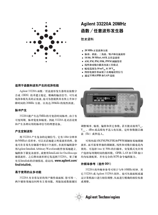
Agilent33220A 20MHz函数任意波形发生器
/find/emailupdates 得到您所选择的产品和应用的最新信息。
Agilent 测试和测量软件及连通性 Agilent 测试和测量软件及连通性产品、解决方案和开发网能使您容易地使用基于 PC 标
准的工具,把仪器接到计算机上,从而能集中关注您的任务,而不必为连接问题分心。要了 解更详细的情况,请访问:/find/connectivity。
正弦波,方波,斜波,任意波形 内部 / 外部 正弦波,方波,斜波,三角波,噪声,任意波形 (2mHz - 20kHz) 0.0°- 360.0°
2
PWM
载波波形
脉冲
源
内部 / 外部
内调制
正弦波,方波,斜波,三角波,噪声,任意波形
(2mHz - 20kHz)
偏移
0% - 100% 脉冲宽度
FSK
载波波形
不对称性(@50% 占空比) 1% 周期+ 5ns
抖动(RMS)
1ns + 100ppm 周期
斜波,三角波
频率范围 线性度
1µHz - 200kHz <0.1% 峰输出
可变对称性
0.0% - 100.0%
脉冲
频率范围 脉冲宽度
500µHz - 5MHz 20ns 最小
(周期≤ 10s)
10ns 分辨率
可变沿时间
< 13ns - 100ns
过冲
< 2%
抖动(RMS)
300ps + 0.1ppm 周期
噪声
带宽Βιβλιοθήκη 10MHz,典型值任意波形
频率范围
1µHz - 6MHz
波形长度
2 - 64K 点
幅度分辨率
Agilent 33210A 10MHz 函数 任意波形发生器 说明书
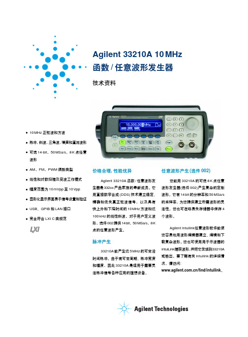
Agilent 33210A 10MHz函数/任意波形发生器技术资料10MHz正弦波和方波脉冲,斜波,三角波,噪声和直流波形可选14-bit,50MSa/s,8K点任意波形AM,FM,PWM调制类型线性和对数扫描及突波工作模式幅度范围为10mVpp至10Vpp图形化显示界面易于信号设置和验证USB、GPIB和LAN接口完全符合LXI C类规范任意波形产生(选件002)您能用33210A的可选8K点任意波形发生器(选件002)产生复杂的定制波形。
它有14bit的分辨率和50MSa/s的采样率,为您提供建立所需波形的灵活性。
您也可在非易失存储器中保存4个波形。
Agilent Intuilink任意波形软件能使您容易地用波形编辑器建立、编辑和下载复杂波形。
您也可使用用于示波器的IntuiLink捕获波形,并把它发送到33210A或输出。
要了解有关Intuilink的详细情况,请访问:/find/intuilink。
价格合理, 性能优异Agilent 33210A函数/任意波形发生器是332xx产品家族的最新成员。
它用直接数字合成(DDS)技术建立稳定、精确和低失真正弦波信号,以及具有快上升和下降时间的10MHz方波和达100kHz的线性斜波。
对于用户定义波形,选件002提供14bit,50MSa/s,8K点的任意波形产生。
脉冲产生33210A能产生达5MHz的可变沿时间脉冲。
由于有可变周期、脉冲宽度和幅度,因此33210A是适用于需要灵活脉冲信号各种应用的理想设备。
易于使用的众多功能33210A具有直接和友好的前面板操作功能。
可以通过一、两个按键访问所有主要功能,并通过旋钮或数字键区调整频率、幅度、偏置和其它参数。
甚至能以Vpp、Vrms、dBm或高低电平设置电压值,并能以赫兹(Hz)或秒设置定时参数。
内部AM, FM和PWM调制功能可以容易地调制波形,而不需要单独的调制源。
线性和对数扫描也是内置的,可选择1ms至500s的扫描速率。
Agilent N9310A 射频信号发生器 说明书

全量程输入: 调制频率范围:
载波抑制: QPSK EVM: GMSK 相位误差: 连接端口和输入阻抗:
外部 I/Q 输入 < 1.5 (I2+Q2)=0.5 Vrms DC to 40 MHz 40 dBc 3% 1.2° rms BNC 阴头; 50 Ω
远控
USB 主控端口: 3xA 插口 USB 设备端口: 1xB 插口
分辨率: 调制频率: 偏移精度: 总谐波失真: 外部输入:
灵敏度: 输入阻抗:
(载频 100 KHz 以上)
内部 0 到 10 rad 0 到 5 rad < 1% 300 Hz 到 20 kHz. < ± (设置值的 5% + 0.2 rad) < 1.5%
1 Vp BNC; >100 kΩ (标称值)
汉英双语提升了产品的通用性
随着业务的全球化拓展,您的工程 师和技术人员遍布世界各地。因此, 在多语言环境下操作测量仪器的挑 战实际上已经成为一个基本的需求。
对此需求,N9310A射频信号发生器 可以迎刃而解。
针对屏幕上显示的操作信息, N9310A 射频信号发生器内置了英 语和汉语两种语言。不久,其它语言 的选件也将陆续推出。
6
经济合理的价格、迅速完美的支持 当您在教学、生产、研发、安装过程或 者维护计划中使用安捷伦的测试仪器 时,一旦遇到难题,您可以信赖安捷伦 — 您将获得令您满意的客户支持。 您可以深信,您正在做物有所值的正 确选择。
实用性的价值对您意味着什么
安捷伦科技新一代结构紧凑、成本低廉的测试仪器系列
我们深信安捷伦的 N9310A 射频 信号发生器能够充分满足您的需 求,请体验它的实用性,满怀信心 的订购。
Agilent N9310A信号发生器介绍

is 50Ω。其精确度由使用的时基决定。
⑥ 参考输入端口 可以接收) 电平为 3.5 到 +20 dBm 的参考信号。 标称输入阻抗为 50Ω。 当选择相应频率的
d 发生器便进入待机模式同时前面板橙色的待机指示灯被点亮。
② 电源接口 插入随仪器提供的 3 芯电源线,连接外部电源插座。
e ③ USB 接口 (Host) 用以实现仪器和 PC 机通信。 r ④ 触发输入端口 可以接收 TTL 信号进行触发操作。外部 TTL 信号的电平时间不可 te 小于 100 ns。触发操作时您可以上升沿触发或下降沿触发。
te • 0 到 3 Vp 的 50 W 匹配低频输出
• 低频扫描功能
is • 6.5 英寸 TFT 液晶显示屏
• 通用 USB 接口
UnReg 1.1 前面板概述
① 显示屏 液晶屏显示有关当前功能的信息,包括状态指示符频率和幅度设置以及错 误信息。软功能键的标签位于显示屏的右侧。
② 软按键 用于激活显示屏右侧对应按钮所指示的功能或选项。 ③ 确认键 (Enter) 用于确认通过旋钮或数字键完成编辑的数值输入,或触发单次扫
附录 2.2 Agilent N9310A 信号发生器介绍
1 概述
d 安捷伦 N9310A 射频信号发生器具有如下主要特征:
• 9 kHz 到 3 GHz 的频率范围
e • –127 dBm 到 +13 dBm 的幅度范围(可设置到 +20 dBm r • 调幅、调频、调相以及脉冲调制功能
• 幅度、频率的步进扫描功能
dBm 的反向输入功率或 30 V 的直流电压输入(持续时间不超过 1 分钟),否则, 内部电路可能受损。
安捷伦仪器使用说明书中文

Alpha安捷伦B1500A半导体器件分析仪用户!ˉ的GUID安捷伦科技公司声明?安捷伦科技公司2005年,2006年,2007年,2008本手册的任何部分不得转载任何形式或通过任何手段(包括电子电子存储和检索或翻译成外国语言)事先同意MENT和安捷伦的书面同意作为由美国科技公司在美国和国际版权法。
手册部件号B1500-90000版2005年7月第1版,第2版,2005年12月2006年4月第3版第4版,2007年1月2007年6月5日,版第6版,2007年11月2008年10月7日,版安捷伦科技公司5301史蒂文斯溪大道95051美国加利福尼亚州圣克拉拉保证本文档中所含的物质是提供MENT!°为是,±,是苏如有更改,恕不另行通知,在以后的版本。
此外,最大而且,在适用法律法律,安捷伦提供任何保证,明示或暗示,关于本手册的任何信息所载,包括但不不限于隐含保证为杆的适销性和适用性特定用途。
安捷伦不得承担错误或偶然或在相应的损害赔偿连接TION的家具,使用,或每本文件或任何性能所载资料。
应该安捷伦与用户有一个单独的与保修的书面协议在这个物质的范围,涵盖记录与这些冲突条款,在保修则以协议arate中的协议为准。
技术许可硬件和/或软件描述这份文件是依照许可可用于复制或只在雅跳舞的许可条款。
有限权利如果软件在使用的一种表现美国政府的首要合同或道,软件交付和许可!°商业计算机软件!±ADFAR252.227-7014(1995年6月)的定义,或作为一个!°商业项目!FA±定义2.101(a)或°有限计算机软!洁具!±作为定义在FAR52.227-19(六月1987)或任何相当机构法规或合同条款。
使用,重复或disclo的软件肯定是受安捷伦科技nologies!ˉ标准商业许可条款和非DOD部门和美国政府机构没有获得更大而不是限制权利定义在FAR 52.227-19中(C)(1-2)(6月1987年)。
Agilent信号发生器使用规范

目录1. 操作面板按钮介绍 (3)2. 相关提示 (4)3. 使用准备工作 (5)4. 波形参数设置 (6)4.1 设置输出频率 (6)4.1.1 按下“Freq”软按键 (6)4.1.2 输入理想频率的数值 (7)4.1.3 选择合适的单位 (7)4.2 设置输出振幅 (7)4.2.1 按下“Ampl”软按键 (7)4.2.2 输入理想振幅的数值 (8)4.2.3 选择合适的单位 (8)4.2.4 进入数字输入模式 (9)4.2.5 选择新的单位 (9)4.3 设置直流电偏置电压 (9)4.3.1 按下“Offset”软按钮 (10)4.3.2 输入理想的偏置电压数值 (10)4.3.3 选择合适的单位 (10)4.4 设置高电平和低电平值 (11)4.4.1 按下“Ampl”按钮选择“Ampl” (11)4.4.2 再次按下这个按钮选择“Hilevel” (11)4.4.3 设置“Hilevel”值 (11)4.4.4 按下“Lolevel”并且设置这个值 (11)4.5 选择直流电压 (12)4.5.1 按下这个按钮,然后选择 DC ON 按钮 (12)4.5.2 输入一个理想电压值作为一个偏置量 (12)4.6 设置方波的占空比 (13)4.6.1 选择方波函数 (13)4.6.2 按下“Duty Cycle”按钮 (13)4.6.3 输入理想的占空比 (13)4.7 设置一个脉冲波形 (14)4.7.1 选择脉冲函数 (14)4.7.2 设定脉冲周期 (14)4.7.3 设置脉冲的脉宽 (14)4.7.4 设置斜坡时间 (14)4.8 观察一个波形的图像 (15)4.8.1 打开图像模式 (15)4.8.2 选择理想的参数 (15)4.9 选择输出终端 (16)4.9.1 按下键。
(16)4.9.2 操作菜单来设置输出终端。
(16)4.9.3 设定理想的输出终端 (16)4.10 重置函数发生器 (16)Agilent 函数发生器使用入门指南1. 操作面板按钮介绍前面板(如下图):1-------图形模式键 2-------开关键3-------调制/扫描/脉冲键 4-------状态存储菜单键5-------有效菜单键 6-------帮助菜单键7-------菜单操作键 8-------波形选择键9-------手动触发键(仅用于扫描和脉冲) 10-------输出开关键11-------旋钮 12-------方向键13-------同步连接接头 14-------输出连接接头当某一个按钮被按下时,这个按钮被点亮,如上图中8号中sine 波形按钮。
Agilent安捷伦功率器件分析仪-操作指导说明
Scale:选择曲线显示格式
Anode:二极管正极接电流源(依据
规格书测试条件合理选择,大于 1A
VF 测试-方法二
则需要选择 HC 通道) VfStart:开始电压
3.2 3.2 参数设置
VfStop:结束电压 VfStep:每个测试点电压间隔值
均有“Force”和“Sence”双孔,实 际内部相当于短路,即通过双线并 绕以降低测试误差; 应用 HC 模块时,下方 low 双孔默认 接地即可; 可看成将 HP/HC/HV 作为电源正极, GNDU1 作为电源负极
Agilent 安捷伦功率器件分析仪-操作指导说明
测试台说明: 2.2
2.2 接线模块
2.3 数据读取
▷ 点击“ ”启动测试;
完成测试后点击自动刻度; List Display 下拉数据,可以查看每个
Vr 下的反向漏电流 Ir,一般 Ir=250μA 时对应的最小 Vr 作为击穿电压
Agilent 安捷伦功率器件分析仪-操作指导说明
VF 测试 3.1
3.1 连线
按测试电路原理图,正确连接各接线柱。
IfSpec@Vf:自动读取所设正向电流
下对应的正向压降
Agilent 安捷伦功率器件分析仪-操作指导说明
▷ 点击“ ”启动测试;
完成测试后点击自动刻度;
VF 测试-方法一 List Display 下拉数据,可以查看每个
3.3
If 下的正向压降 Vf
3.3 数据读取
Agilent 安捷伦功率器件分析仪-操作指导说明
依 次 从 Application Test 选 择 PowerDiode,再选择 Ir-Vr 测试模块:
VR/IR 测试 2.2
Agilent软件操作说明书1.1
Agilent软件操作说明书Agilent软件操作说明书 (1)1 概述 (2)更新时间 (2)版本 (2)更新内容 (2)2008.9.15 (2)V1.1 (2)1.添加License申请 (2)2.添加软件存在问题总结 (2)3.添加前台reporter应用功能 (2)2 功能介绍 (2)2.1 License的安装 (2)2.2 运行软件 (5)2.3 创建工程 (6)2.4 设备添加..................................................................................... 错误!未定义书签。
2.5 导入基站数据 (16)2.6 测试过程中的界面试图 (22)2.7 测试脚本的配置 (28)2.7.1 Call_Control (29)2.7.2 FTP下载 (30)2.8 Report的分析 (35)2.9 数据卡的使用 (40)3 附件 (44)1概述通过Agilent软件能够对该地区的3G网络的进行测试,包括语音电话,视屏电话,FTP下载等,结合测试结果发现3G网络中存在的问题,为3G的网络优化提供必要的依据。
2功能介绍2.1 License的安装在运行软件之前需要安装license得到软件的使用权。
如何获取Agilent E6474 License1.若无License,则MapX不能正确显示2.选择Programe File/Agilent Wireless Solution/E6474-X/Utilities/License Manager3.选择Commuter License中的Remote Commuter License,得到Current Computer 的MachineCode,发送给相关人员获取License.中Load并安装,即OK2.2 运行软件如上图所示,打开软件后出现上图所示的界面,点击红色区域中的Collect data now按钮进入软件。
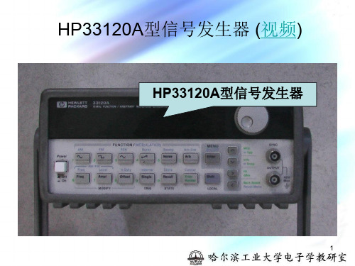
HP33120A型信号发生器(视频)ppt课件
本仪器可将三个不同的仪器状态存入永久存储单元中 去,并可随时调用。存储步骤:首先设定所要存储的波形, 包括波形形状、频率、幅值、直流偏移量及其他参数。然 后按Shift Store,显示屏上出现存储单元的编号 ,
7
用上、下方向键或旋钮选择存储单元(但不可选择Store0, Store0用来存储关机前的状态,开机后可重新调用)。如 选择Store2,按Enter键,则波形已被存入“存储单元2 中”。调用时,先按Recall键,再用上、下方向键或旋钮 改变所显示的存储单元序号,至Store2时,按Enter键。 此时信号发生器输出的即为所存储的波形。
注意:输出端的探头或夹子切不可直接接至正、负电源, 否则会损坏信号源的输出级。
8
5
按Enter Number键输入一带有符号的数字(使用 ± 键使输入数字在“+”、“”之间切换),再用上、下、 右三个方向键输入单位(分别为“Vpp”、“Vrms”和 “dBm”)。如在幅度或直流偏移量修改模式下,选择单 位为“mVpp”或“mVrms”,则应先按Shift键转换到蓝色字 体所标识的功能上,再按方向键,才能正确地输入单位。 如输入数字后,不选择单位,直接按Enter键,则仅输入 数字,不改变单位。如想取消数字输入功能,请按Shift 键,然后按Cancel键即可。
HP33120A型信号发生器 (视频)
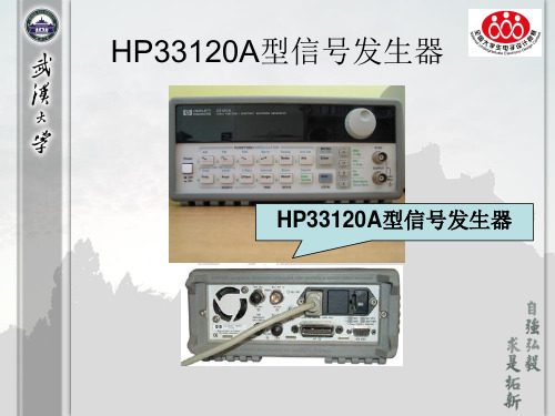
HP33120A型信号发生器
1
开关
微调旋钮
功能按 键
输出
2
3
该信号发生器的面板图如图2.3.1所示。
一. 电源开关(Power)
将此键按至“ON”位置,打开信号发生器。此时信号 发生器输出一频率为1kHz、峰峰值为100mV的正弦波。
安捷伦函数信号发生器Agilent 33120A的性能与使用说明
安捷伦函数信号发生器Agile nt 33120A 得性能与使用说明安捷伦函数信号发生器33120A 就是数字式函数信号发生器。
其内部永久存储着正弦波、方波、三角波、噪声、锯齿波、sin(x)/x 、负锯齿波、指数上升波、指数下降波、心电波,共10种函数信号。
其中,正弦波、方波得频率范围为100μHz-15MHz,幅值范围为100mV P -P -10V P-P 。
函数信号发生器有一个HP -IB(I EEE-488)接口与一个RS-232接口,计算机通过接口可遥控函数信号发生器,在计算机中使用HP BA SIC 语言程序或C 语言程序,能产生12bit 40Msa /s 得任意波形,通过接口写入函数信号发生器,函数信号发生器有四个可存储16000点得任意波形存储器。
其具体得性能指标与基本操作方法见本节后摘录自“Agi le nt 33120A Fu ncti on Ge ne rator Us er Gu ide ”得内容。
要知道详细得内容应阅读该仪器得“用户手册”。
⒈ 信号源显示电压与实际输出电压理想信号源得内阻应为零。
若实际信号源得内阻为零,则 信号源输出端一旦短路或负载电阻过小,信号源就会因功率过 载而损坏。
实际信号源一般都在其输出端串接一个电阻R s , 使信号源既使短路,在短时间内也不会因功率过载而损坏,由此使信号源得保护电路有时间实现对信号源输出电路进行保护, 同时发出过载警告。
称信号源输出端串接电阻Rs 为信号源内阻。
安捷伦33120A(以下简称为信号源)得内阻为50Ω。
由于有了信号源内阻R s ,如图1,信号源输出端得电压,即负载电阻RL上得电压,就是信号源得电源E s 在信号源内阻R s 与负载电阻R L上得分压,即V o ≠Es 。
信号源内设置了两个负载电阻值,开机时默认为R LD =50Ω,通过操作可修改为R L D→∞。
在信号源开机默认为R LD =50Ω时,信号源内部得电压源输出得电压为E s ,信号源显示屏上显示得电压就是(1)若实际负载不就是50Ω,那么负载上实际得到得电压Vo为(2)即信号源显示屏上显示得电压与负载上得到得实际电压不一样,Vo ≠VDispl ay 。
Agilent 使用说明
安捷伦电子测量仪器使用及维护建议版本. 03.08Agilent Technologies Co. SSU-----------Be Professional , Be Expert-------目录静电的危害及防护 (3)微波接头的使用及养护常识 (12)电子测量仪器及其系统的环境要求 (16)仪器硬件故障的最终确认 (21)附录一:部分种类仪器的用户检验步骤及注意事项 (23)附录二:Agilent仪器常见故障现象及可能原因分析 (27)附录三:参考资料 (29)静电的危害及防护引言.我们在确定自己的研究课题或找到解决方案时,下一步往往就是准备好完成课题或解决方案所需的软硬件手段.而测量仪器是人们必备的硬件设施.在得到仪器后,如何高效地使用仪器,或如何避免仪器的人为损坏,能够更长时间地为我们服务,就自然而然地成为我们必须关心的环节了.静电的危害那么哪些因素可以影响或威胁到仪器的正常使用呢?了解电子测量仪器或微电子的工程师所想到的第一个词,我想必定是”静电放电”(ESD).的确,静电是我们再熟悉不过的一种现象了,除了偶而轻微电击或讨厌的静电吸附外,对我们大多数人来讲,静电似乎并不是什么了不起的问题.过去,许多从事电子工业的人也并不认为静电放电是使电子元件乃至整个电子设备损坏的一个主要原因.许多人不相信静电放电的严重性,甚至怀疑是否真正存在.这也难怪,因为要判断或检查ESD(静电放电简称-Electrostatic Dischar ge)所引起的失效比较困难,有些元件受ESD损伤后往往在经过一段时间后才失效,使人们难于追踪并确定为ESD引起的损坏.而且许多电子元件可以被远低于人能感觉的静电放电所损伤或损坏.无源器件也和有源器件一样对ESD敏感,损坏程度从性能下降直至短路那样的严重损坏.目前,许多人对自己身上常常带可观的静电以至常常受静电放电电击的现象习以为常了.可是,您知道吗?当你的手触摸及门把手或水龙头的瞬间突然感受到受电击甚至听到”啪”的一声响之时,你身上的静电已高达4000至5000伏以上了.而且.在受电击之前,你并没有任何感觉.实际上,人的身体上,衣服上经常带有几百伏到几千伏的静电.只要构成通路,积累的静电就会放电.由于在极短的时间内释放出大量的能量,常常导致电路元件损坏,因为这种放电通常大大超过许多电路元件所能承受的限度.据测试,人能感觉到”麻”时,静电电压已高达3500伏以上.高于4500伏时放电能发出响声.5000伏以上放电时可以见到火花.人感觉不到3500伏以下的静电. 现代许多高速超大规模集成电路碰到仅几十伏或更低的静电就会遭到损坏。
Agilent Technologies 33120A功能 随机波形生成器说明书
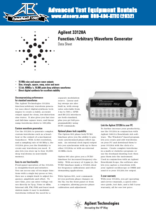
Uncompromising performance for standard waveformsThe Agilent Technologies 33120A function/arbitrary waveform genera-tor uses direct digital-synthesis tech-niques to create a stable, accurate output signal for clean, low-distortion sine waves. It also gives you fast rise-and fall-time square wave, and linear ramp waveforms down to 100µHz.Custom waveform generationUse the 33120A to generate complex custom waveforms such as a heart-beat or the output of a mechanical transducer. With 12-bit resolution,and a sampling rate of 40MSa/s, the 33120A gives you the flexibility to create any waveform you need. It also lets you store up to four 16,000-deep waveforms in nonvolatile memory.Easy-to-use functionalityFront-panel operation of the 33120A is straightforward and intuitive. You can access any of ten major func-tions with a single key press or two,then use a simple knob to adjust fre-quency, amplitude and offset. To save time, you can enter voltage val-ues directly in Vp-p, Vrms or dBm.Internal AM, FM, FSK and burst mod-ulation make it easy to modulate waveforms without the need for aseparate modulation source. Linear and log sweeps are also built in, with sweep rates selectable from 1ms to 500 s. GPIB and RS-232 interfaces are both standard, plus you get full pro-grammability using SCPI commands.Optional phase-lock capabilityThe Option 001 phase lock/TCXO timebase gives you the ability to gen-erate synchronized phase-offset sig-nals. An external clock input/output lets you synchronize with up to three other 33120As or with an external 10-MHz clock.Option 001 also gives you a TCXO timebase for increased frequency sta-bility. With accuracy of 4 ppm/yr, the TCXO timebase make a 33120A ideal for frequency calibrations and other demanding applications.With Option 001, new commands let you perform phase changes on the fly, via the front panel or from a computer, allowing precise phase calibration and adjustment.Link the Agilent 33120A to your PCTo further increase your productivity,use the 33120A in conjunction with Agilent 34811A BenchLink Arb soft-ware. The Windows®-based program lets you create and edit waveforms on your PC and download them to your 33120A with the click of amouse. Create complex waveforms in a math or statistics program—or use the freehand drawing tool—then pass them into the instrument. Used in conjunction with an Agilent BenchLink Scope, the software also lets you capture a waveform withyour Agilent oscilloscope or DMM and send it to your 33120A for output.3-year warrantyWith your 33120A, you get operating and service manuals, a quick refer-ence guide, test date, and a full 3-year warranty, all for one low price.• 15 MHz sine and square wave outputs• Sine, triangle, square, ramp, noise and more• 12-bit, 40MSa/s, 16,000-point deep arbitrary waveforms •Direct digital synthesis for excellent stabilityAgilent 33120AFunction/Arbitrary Waveform GeneratorData Sheet1981WaveformsStandard Sine, square, triangle, ramp,noise, sin(x)/x, exponentialrise exponential fall, cardiac,dc volts.ArbitraryWaveform length8 to 16,000 points Amplitude resolution12 bits (including sign) Sample rate40 MSa/sNon-volatile memory Four (4) 16,000 waveforms Frequency CharacteristicsSine100 µHz - 15 MHzSquare100 µHz - 15 MHz Triangle100 µHz - 100 kHzRamp100 µHz - 100 kHzWhite noise10 MHz bandwidth Resolution10 µHz or 10 digits Accuracy10 ppm in 90 days,20 ppm in 1 year,18°C - 28°CTemp. Coeff< 2 ppm/°CAging< 10 ppm/yr Sinewave Spectral PurityHarmonic distortiondc to 20 kHz-70 dBc20 kHz to 100 kHz-60 dBc100 kHz to 1 MHz-45 dBc1 MHz to 15 MHz-35 dBcSpurious (non-harmonic)DC to 1 MHz< -65 dBc1 MHz to 15 MHz< -65 dBc + 6 dB/octave Total harmonic distortionDC to 20 kHz<0.04%Phase noise<-55 dBc in a 30 kHz band Signal CharacteristicsSquarewaveRise/Fall time< 20 nsOvershoot4%Asymmetry1% + 5nsDuty cycle20% to 80% (to 5 MHz)40% to 60% (to 15 MHz) Triangle, Ramp, ArbRise/Fall time40 ns (typical)Linearity<0.1% of peak output Setting Time<250 ns to 0.5% offinal valueJitter<25ns Output CharacteristicsAmplitude (into 50Ω)50 mVpp - 10 Vpp [1]Accuracy (at 1 kHz)±1% of specified outputFlatness (sinewave relative to 1 kHz)< 100 kHz±1% (0.1 dB)100 kHz to 1 MHz±1.5% (0.15 dB)1 Mz to 15 MHz±2% (0.2 dB) Ampl ≥3Vrms±3.5% (0.3 dB) Ampl<3VrmsOutput Impedance50Ω(fixed)Offset (into 50Ω) [2]+ 5 Vpk ac + dcAccuracy±2% of setting + 2 mVResolution 3 digits, amplitude and off-setUnits Vpp, Vrms, dBmIsolation42 Vpk maximum to earthProtection Short circuit protected±15Vpk overdrive < 1 minuteModulationAMCarrier -3dB Freq.10 MHz (typical)Modulation any internal waveformincluding ArbFrequency10 mHz - 20 kHzDepth0% - 120%Source Internal/ExternalFMModulation any internal waveformincluding ArbFrequency10 mHz - 10 kHzDeviation10 mHz - 15 MHzSource Internal onlyFSKInternal rate10 mHz - 50 kHzFrequency Range10 mHz - 15 MHzSource Internal/External(1 MHz max.)BurstCarrier Freq. 5 MHz max.Count 1 to 50,000 cycles or infiniteStart Phase-360°to +360°Internal Rate10 mHz - 50 kHz ±1%Gate Source Internal/External GateTrigger Single, External orInternal RateSweepType Linear or LogarithmicDirection Up or DownStart F/Stop F10 mHz - 15 MHzSpeed 1 ms to 500 s ±0.1%Trigger Single, External, or InternalRear Panel InputsExt. AM Modulation±5 Vpk = 100% modulation5kΩinput resistanceExternal Trigger/TTL low trueFSK/Burst GateSystem Characteristics[3]Configuration Times[4]Function Change:[5]80 msFrequency Change:[5]30 msAmplitude Change:30 msOffset Change:10 msSelect User Arb:100 msModulation ParameterChange:<350 msArb Download Times over GPIBArb Length Binary ASCII Integer ASCII Real[6]16,000 points8 sec81 sec100 sec8,192 points 4 sec42 sec51 sec4,096 points 2.5 sec21 sec26 sec2,048 points 1.5 sec11 sec13 secArb Download Times over RS-232 at 9600 Baud:[7]Arb Length Binary ASCII Integer ASCII Real[8]16,000 points35 sec101 sec134 sec8,192 points18 sec52 sec69 sec4,096 points10 sec27 sec35 sec2,048 points 6 sec14 sec18 sec[1] 100 mVpp - 20 Vpp into open circuit[2] Offset ≤2x pk - pk amplitude[3] Times are typical. May vary based on controllerperformance[4] Time to change parameter and output the newsignal.[5] Modulation or sweep off[6] Times for 5-digit and 12-digit numbers[7] For 4800 baud, multiply the download times bytwo; For2400 baud, multiply the download timesby four, etc.[8] Time for 5-digit numbers; for 12-digit numbers,multiply the 5-digit numbers by two2Option 001 Phaselock/TCXO TimebaseTimebase AccuracySetability< 0.01 ppmStability±1 ppm 0°- 50°Aging< 2ppm in first 30 days(continuous operation)0.1 pm/month(after first 30 days)External Reference InputLock Range10 MHz ±50 HzLevel-10 dBm to + 15 dBm+25 dBm or 10 Vpp maxinputImpedance50Ω±2%, 42 Vpk isola-tion to earthLock Time< 2 secondsInternal Reference OutputFrequency10 MHzLevel> 1 Vpp into 50 ΩPhase OffsetRange+ 360°to - 360°Resolution0.001°Accuracy25 nsTrigger OutputLevel5V zero-going pulse Pulse Width> 2µs typicalFanout Capable of driving up tothree 33120As Ordering InformationAgilent 33120A Function/Arb GeneratorOpt. 001 Phase Lock/TCXO Timebase Option GeneralPower Supply110V/120V/220V/240V ±10%Power Line Frequency45 Hz to 66 Hz and 360 Hzto 440 HzPower Consumption50VA peak (28 W aveage) Operating Environment0°C to 55°CStorage Environment-40°C to 70°CState Storage Memory Power Off state automati-cally saved, 3 UserConfigurable StoredStatesInterface IEEE-488 and RS-232standardLanguage SCPI - 1993, IEEE-488.2 Dimensions (W x H x D)Bench top254.4mm x 103.6mm x374mmRack mount212.6mm x 88.5mm x348.3mmWeight 4 kg (8.8 lbs)Safety Designed to UL-1244, CSA 1010,EN61010EMC Tested to MIL-461C, EN55011,EN50082-1Vibration and Shock MIL-T-28800, Type III,Class5Acoustic Noise30 dBaWarm-up Time 1 hourWarranty 3 years standard3Ordering Information33120A Function/Arbitrary Waveform GeneratorAccessories includedOperating manual, service manual, quick reference guide, test data, and power cordOptionsOpt. 001Phase lock/TCXO timebaseOpt. 106BenchLink Arb software (34811A)Opt. 1CM Rack Mount Kit (34190A)*Opt. W50Additional 2-year warranty (5-year total)Opt. 910Extra manual setManual language options (please specify one)ABA US EnglishABD GermanABE SpanishABF FrenchABJ JapaneseABZ ItalianABO Taiwan ChineseAB1 KoreanAccessoriesAgilent 34161A Accessory pouchAgilent 34811A BenchLink Arb software*For racking two side-by-side, order both items belowLock-link Kit (P/N 5061-9694)Flange Kit (P/N 5063-9212)Windows®is a U.S. registered trademark of Microsoft Corporation.Agilent Technologies’ Test and Measurement Support, Services, and AssistanceAgilent Technologies aims to maximize the value you receive, while minimizing your risk and problems. We strive to ensure that you get the test and measure-ment capabilities you paid for and obtain the support you need. Our extensive sup-port resources and services can help you choose the right Agilent products for your applications and apply them successfully. Every instrument and system we sell has a global warranty. Support is availablefor at least five years beyond the produc-tion life of the product. Two concepts underlie Agilent’s overall support policy:“Our Promise” and “Your Advantage.”Our Promise“Our Promise” means your Agilent test and measurement equipment will meet its advertised performance and functionality. When you are choosing new equipment, we will help you with product informa-tion, including realistic performance spec-ifications and practical recommendations from experienced test engineers. When you use Agilent equipment, we can verify that it works properly, help with product operation, and provide basic measurement assistance for the use of specified capabil-ities, at no extra cost upon request. Many self-help tools are available.Your Advantage“Your Advantage” means that Agilent offers a wide range of additional expert test and measurement services, which you can purchase according to your unique technical and business needs. Solve prob-lems efficiently and gain a competitive edge by contracting with us for calibration,extra-cost upgrades, out-of-warranty repairs, and on-site education and training, as wellas design, system integration, project man-agement, and other professional services. Experienced Agilent engineers and techni-cians worldwide can help you maximize your productivity, optimize the return on investment of your Agilent instruments and systems, and obtain dependable measure-ment accuracy for the life of those products. Get assistance with all yourtest and measurement needs at:/find/assistOr check your local phone book for the Agilent office near you.Product specifications and descriptions inthis document subject to change without notice. Copyright © 1998, 2000 Agilent Technologies Printed in U.S.A. 4/005968-0125EN。
HP33120A型信号发生器
三.有关参数设定
对于某一波形,需要调整的参数一般为频率、幅 度和直流偏移量。我们可以通过按下Freq、Ampl和 Offset三个功能键启动相应的修改模式。 如:按下Ampl键,屏幕显示出当前输出信号的 幅度值,在此状态下可进行输出信号幅度的调整。 两种方式实现: 1.显示屏上有一位闪烁的数字,其大小可以通过 旋钮或上下方向键改变,而闪烁数字的位置可以用左 右方向键调整,由其位置不同,可实现粗调和微调。 如要修改的数字量大,应将闪动位的数字调至高位, 再旋转旋钮,避免浪费时间和仪器磨损;
六.仪器状态的存储及调用
本仪器可将三个不同的仪器状态存入永久存储 单元中去,并可随时调用。存储步骤:首先设定所 要存储的波形,包括波形形状、频率、幅值、直流 偏移量及其他参数。然后按Shift Store,显示屏上 出现存储单元的编号 。
用上、下方向键或旋钮选择存储单元(但不可 选择Store0,Store0用来存储关机前的状态,开机后 可重新调用)。如选择Store2,按Enter键,则波形 已被存入“存储单元2中”。调用时,先按Recall键, 再用上、下方向键或旋钮改变所显示的存储单元序号, 至Store2时,按Enter键。此时信号发生器输出的即 为所存储的波形。 注意:输出端的探头或夹子切不可直接接至正、负电 源,否则会损坏信号源的输出级。
设置和产生扫描信号
设置好某一段频率范围的扫描信号,从放大 器的输入端输入,可以测出该放大器的幅频特性 以及滤波器的幅频特性。
设置起始频率:
• 1、先按“功能切换”(Shift)按钮,再按“(扫 描)”(Sweep)按钮,这时屏幕下方有“Swp”字样出 现 • 2、按“波形频率”(Freq)按钮可以调节输出波形频 率;按“幅度”(Ampl) 按钮可以调节输出波形幅度 大小,方法同前。 • 3、输出波形频率和幅度调好后,先按“功能切 换”(Shift) 按钮,再按“回车键”(Enter),屏幕先 显示“MENUS”字样并很快消失,显示“A: MOD MENU”字样 • 4、按键盘上的“→”键,“A:”变成“B: SMP MENU” 字样,并且“B:” 字样在闪烁
安捷伦ESA系列频谱仪使用手册中文版

第一章: 信号分析技术简介
第一章: 信号分析技术简介
连续波信号 模拟调制信号 数字调制信号 噪声信号
MMoodduullaattiioonn
时域分析 频域分析 调制域分析
NNooiissee
完整的信号分析内容
带带内内测测试试项项目目
带带外外测测试试项项目目
频道内
{(In-channel) 频道外
21.4 MHz Out
IF Processing
amp
filter
det
300 MHz
LO
LO
中频滤波器
IF FILTER
Input Spectrum IF Bandwidth (RBW)
Display
检波器
"bins"
Detector 幅度
视频滤波器
VIDEO FILTER
技术小结
Ø 完成频谱分析有:扫频式和FFT两种方式; Ø FFT适合于窄分析带宽,快速测量场合; Ø 扫频方式适合于宽频带分析场合; Ø 单点频CW信号在扫频式频谱仪上测试显示的结果 为 中频滤波器形状。
信号源1
信号源2
频谱仪
f1
f 1 + 10 kHz
耦合器
衰减器
带通滤波器
In 被测件
调制信号的矢量描述
BPSK
DQPSK and QPSK
π/4 DQPSK
16QAM
32QAM
MSK
8 PSK
调制信号的误差
Er幅r度o误r 差Vector Concept
Q
{
实际信号
误差失量
φ
标准参考信号
Error Vector Magnitude (EVM)
NI Multisim 11.0中函数信号发生器的使用word精品文档10页
NI Multisim 11.0中函数信号发生器的使用NI Multisim 11.0是美国国家仪器有限公司(National Instruments,简称NI)推出的以Windows为基础的一个专门用于电子电路仿真与设计的EDA工具软件,用户界面友好,简单易用,提供了功能强大的电子仿真设计界面和方便的电路图及文件管理功能。
Multisim 11.0提供的直观图形化环境可使学生快速放置基本组件,帮助他们掌握电路基础概念和理论。
更重要的是,Multisim 11.0包含丰富的元器件,并将安捷伦测试仪器引入虚拟仪器中,使用户在使用Multisim 11.0时能产生身临其境的感觉。
一、NI Multisim 11.0中函数信号发生器的种类和功能1.NI Multisim 11.0中函数信号发生器的种类NI Multisim 11.0中提供了20多种在电工电子电路分析中常用的仪器仪表,其中的函数信号发生器有2种,一种是虚拟函数信号发生器,打开NI Multisim 11.0软件后,单击仿真/仪器/函数信号发生器后,有一个函数信号发生器的虚影随鼠标移动,在电路窗口相应位置单击鼠标,完成虚拟仪器的放置,得到如图1a所示的函数信号发生器图标,双击该图标,便可以得到如图1b所示的函数信号发生器的参数设置控制面板。
也可以直接从整个工作界面最右侧的仪表工具栏单击拖拽到电路工作窗口。
a 虚拟函数信号发生器图标b 虚拟函数信号发生器控制面板图1 虚拟函数信号发生器另一种是仿真安捷伦(Agilent)函数信号发生器,图2a所示是安捷伦函数信号发生器的图标,图2b所示是安捷伦33120A型函数信号发生器内部参数设置控制面板。
a 安捷伦函数信号发生器图标b 安捷伦33120A型函数信号发生器控制面板图2 仿真安捷伦函数信号发生器2.函数信号发生器的功能函数信号发生器能产生某些特定的周期性时间函数波形(正弦波、方波、三角波、锯齿波和脉冲波、射频和微波等)信号,频率范围可从几微赫到几十兆赫,函数信号发生器在电路实验、信号测试、调整电子电路及设备时具有十分广泛的用途,都要求提供符合所规定技术条件的电信号,以模拟在实际工作中使用的待测设备的激励信号。
安捷伦示波器说明书中英双版

DSOX3PWR 功率量測應用使用者指南s1聲明© Agilent Technologies, Inc. 2007-2009, 2011-2012本手冊受美國與國際著作權法之規範,未經 Agilent Technologies, Inc. 事先協議或書面同意,不得使用任何形式或方法 (包含電子形式儲存、擷取或轉譯為外國語言) 複製本手冊任何部份。
手冊零件編號版本 02.20.0000版本2012 年 7 月 16 日Available in electronic format onlyAgilent Technologies, Inc.1900 Garden of the Gods Road Colorado Springs, CO 80907 USA 保固本文件所含內容係以「原狀」提供,未來版本若有變更,恕不另行通知。
此外,在相關法律所允許之最大範圍內,Agilent 不承擔任何瑕疵責任擔保與條件,不論其為明示或暗示者,其中包括 (但不限於) 適售性、適合某特定用途以及不侵害他人權益之暗示擔保責任。
對於因提供、使用或運用本文件或其中所含的任何內容,以及所衍生之任何損害或所失利益或錯誤,Agilent 皆不負擔責任。
若Agilent 與使用者就本文件所含材料保固條款簽訂其他書面協議,其中出現與上述條款相牴觸之部分,以個別合約條款為準。
技術授權此文件中所述的硬體及/或軟體係依授權提供,且僅可以依據此類授權之條款予以使用或複製。
限制權利聲明美國政府限制權利。
授予聯邦政府之軟體及技術資料僅包含為一般使用者提供的自訂權利。
Agilent 依照 FAR12.211(「技術資料」) 及 12.212 (「電腦軟體」)、國防部 DFARS 252.227-7015 (「技術資料 - 商業條款」) 以及 DFARS227.7202-3 (「商業電腦軟體」或「電腦軟體說明文件」中的權利) 提供此軟體與技術資料之自訂商業授權:安全聲明注意「注意」標示代表發生危險狀況。
安捷伦函数发生器使用详解

如何使用安捷论函数信号发生器(上)(原载《无线电》杂志07年第四期,因版面所限,现将“如何使用安捷伦函数信号发生器”详细原稿分上、下两部分登在网站上供读者学习)在电子仿真软件MultiSIM 9的虚拟仪器工具条中,有三台跨国公司安捷伦仪器虚拟仪器,其中的安捷伦函数信号发生器由于功能多,操作比较复杂,在此对它的设置和使用方法作比较详细地介绍,以飨读者。
虚拟安捷伦函数信号发生器的面板各按钮、旋钮和输入、输出端口等被设计成和实物安捷伦函数信号发生器面板一模一样,这使我们坐在电脑前就能享受到在实验室操作高级仪器的愉悦,且无损坏仪器的担忧。
图1是电子仿真软件MultiSIM 9中的虚拟安捷伦函数信号发生器面板图及各按钮的功能说明,它的型号是Agilent33120A,频宽为15MHz,不仅能产生一般的正弦波、方波、三角波和锯齿波,而且还能产生按指上升或下降的波形等一些特殊的波形,并且还可以由8~256点描述的任意波形。
图1下面结合几个具体例子介绍虚拟函数信号发生器Agilent 33120A的用法:一、选择波形和设置幅度操作:按下“电源开关”(Power)按钮,屏幕默认显示正弦波幅值100.0mVpp~,见图1所示,且百位数“1”处于跳动状态,见鼠标箭头所指。
这时可以按“单位输入”的“∧”、“∨”按钮逐步调整你所需要的正弦波百位数的幅度大小(注:面板上“单位输入”的上、下、左、右箭头和键盘上的上、下、左、右箭头通用,操作效果一样。
);第二种方法是直接按键盘上的数字键,可以改变处于跳动位的数值;第三种方法是用鼠标按住“调节旋钮”作快速调整,顺时针增大,反之减小,适用大范围改变数据。
百位数据调好后,按“单位输入”的“<”、“>”按钮,只要其它位的数字处于跳动状态,即可对该位数字实施上述调整;同样可以按“>”使“mVpp”跳动,配合“∧”、“∨”按钮或“调节旋钮”设置正弦波幅值单位大小,但只能在100mVpp、1.000Vpp和10.00Vpp三者之间选择。
安捷伦33520系列技术资料

内部或外部, 或 33522A 的任意一个通道 脉冲宽度的 0% 至 100%, 0.01% 分辨率
内部或外部, 或 33522A 的任意通道 全载波或双边带抑制载波 0% 至 120%, 0.01% 分辨率
内部或外部, 或 33522A 的任意一个通道 1 µHz 至 15MHz, 1 µHz 分辨率
内部或外部, 或 33522A 的任意一个通道 0° 至 360°, 0.1° 分辨率
内部计时器或外部触发连接器 载波信号范围内的任意频率 0 Hz 至 1 MHz
输出特征
隔离度 输出
信号输出 输出阻抗 (额定值) 启用、关闭、反向 电压限制 过载保护
内置任意波形 幅度 范围
分辨率 单位 精度 1, 2(技术指标) 直流偏置 范围 5
分辨率 单位 精度 1, 2(技术指标)
频率精度
标准频率参考 (技术指标) 一年, 23°C ± 5°C 一年, 0°C 至 55°C 高稳定性频率参考 (技术指标): 选件 010 一年, 0°C 至 55°C
33500 系列具有真正的逐点生成 任意波形能力,可预防混叠 (aliasprotected) 并确保出色的精度,生成更 广泛的波形。在业内同类产品中, 33521A 和 33522A 最先提供 30 MHz 信 号,其中包括常见波形、任意波形和 经过复杂调制的波形。定义任意波形 时,这两个型号均可利用专利技术为 您提供卓越的输入控制功能。这项控 制功能等同于采用多个不同波形序 列,对更复杂的逐点波形进行定义。
任意波形特征
一般特性 波形长度 采样率 电压分辨率 带宽 (-3 dB, 额定值)
- 1、下载文档前请自行甄别文档内容的完整性,平台不提供额外的编辑、内容补充、找答案等附加服务。
- 2、"仅部分预览"的文档,不可在线预览部分如存在完整性等问题,可反馈申请退款(可完整预览的文档不适用该条件!)。
- 3、如文档侵犯您的权益,请联系客服反馈,我们会尽快为您处理(人工客服工作时间:9:00-18:30)。
* *安捷伦函数信号发生器Agilent 33120A的性能与使用说明安捷伦函数信号发生器33120A是数字式函数信号发生器。
其内部永久存储着正弦波、方波、三角波、噪声、锯齿波、sin(x)/x 、负锯齿波、指数上升波、指数下降波、心电波,共10种函数信号。
其中,正弦波、方波的频率范围为100 μHz - 15MHz,幅值范围为100mV P-P -10V P-P 。
函数信号发生器有一个HP-IB ( IEEE-488)接口和一个RS-232接口,计算机通过接口可遥控函数信号发生器,在计算机中使用HP BASIC 语言程序或 C 语言程序,能产生12bit 40Msa/s的任意波形,通过接口写入函数信号发生器,函数信号发生器有四个可存储16000点的任意波形存储器。
其具体的性能指标和基本操作方法见本节后摘录自“ Agilent 33120A Function Generator User Guide”的内容。
要知道详细的内容应阅读该仪器的“用户手册”。
⒈ 信号源显示电压与实际输出电压理想信号源的内阻应为零。
若实际信号源的内阻为零,则信号源输出端一旦短路或负载电阻过小,信号源就会因功率过载而损坏。
实际信号源一般都在其输出端串接一个电阻R s,使信号源既使短路,在短时间内也不会因功率过载而损坏,由此使信号源的保护电路有时间实现对信号源输出电路进行保护,同时发出过载警告。
称信号源输出端串接电阻R 为信号源内阻。
图 1 信号源s输出电压示意图安捷伦 33120A (以下简称为信号源)的内阻为50 Ω。
由于有了信号源内阻 R s,如图 1 ,信号源输出端的电压,即负载电阻 R L上的电压,是信号源的电源E s在信号源内阻R s和负载电阻 R L上的分压,即V o≠E s。
信号源内设置了两个负载电阻值,开机时默认为R LD =50 Ω,通过操作可修改为R LD →∞。
在信号源开机默认为R LD =50 Ω时,信号源内部的电压源输出的电压为E s,信号源显示屏上显示的电压是V DisplayRLD1Es( 1 )R s R LDE s2若实际负载不是50 Ω,那么负载上实际得到的电压V o为V o R L E s 1E s( 2)R s R L2即信号源显示屏上显示的电压与负载上得到的实际电压不一样,V o≠V Display。
在实际使用时,当信号源的负载电阻,即电路的输入电阻R L与 50 Ω可比时,信号源宜取R LD =50 Ω状态,这时 V o≠V Display,但是 V Display比较接近 V o。
信号源的负载电阻,即电路的输入电阻 R L>>50 Ω时,信号源宜取 R LD→∞状态,这时 V o≠V Display,但是 V Display比较接近 V o。
V o究竟为多少应使用电压表具体测量。
⒉ 关于本信号源的具体性能指标和基本操作使用方法以下关于本信号源的具体性能指标和基本操作使用方法摘自“Agilent 33120A Function Generator User Guide”。
直接阅读原版用户手册,比阅读翻译后的用户手册更有利于了解关于本信号源的具体性能指标和基本操作使用方法。
在使用本信号源前,使用者必须阅读以下的内容。
附录Sine: 100 μHz – 15 MHz Square: 100 μHz – 15 MHz Triangle: 100 μHz – 100 kHz Ramp:100 μHz – 100 kHzNoise 10 MHz bandwidth(Gaussian):Arbitrary 8 to 8,192 points:100 μHz – 5 MHz Waveforms:8,193 to 12,287 points: 100 μHz – 2.5 MHz12,288 to16,000100 μHz – 200 kHzpoints:Resolution: 10 μHz or 10 digitsAgilent 33120A Function Generator User GuideSpecificationsWAVEFORMS StandardSine, Square, Triangle, Ramp, Noise, DC volts, Sine(x)/x, NegativeWaveforms: Ramp, Exponential Rise, Exponential Fall, CardiacArbitraryWaveform Length: 8 to 16,000 pointsWaveforms: Amplitude Resolution: 12 bits (including sign)Sample Rate: 40 MSa / secNon-Volatile Memory: Four 16,000-point waveformsFREQUENCY CHARACTERISTICSAccuracy:10 ppm in 90 days, 20 ppm in 1 year, 18℃ – 28 ℃Temperature< 2 ppm / ℃Coefficient:Aging:< 10 ppm / yrSINEWAVE SPECTRAL PURITY(into 50? )Harmonic DC to 20 kHz:-70 dBcDistortion20 kHz to 100 kHz:-60 dBc100 kHz to 1 MHz:-45 dBc1 MHz to 15 MHz:-35 dBcTotal Harmonic DC to 20 kHz:< 0.04%DistortionSpurious Output (DC to 1 MHz):< -65 dBc(non-harmonic)Output (> 1 MHz):< -65 dBc + 6 dB/octave Phase Noise:< -55 dBc in a 30 kHz bandSIGNAL CHARACTERISTICSSquarewave Rise/Fall Time:< 20 nsOvershoot:< 4%Asymmetry:1% + 5 nsDuty Cycle:20% to 80% (to 5 MHz)40% to 60% (to 15 MHz) Triangle,Ramp,Rise/Fall Time:40 ns (typical)Arb Linearity:< 0.1% of peak outputSettling Time:< 250 ns to 0.5% of final valueJitter:< 25 nsOUTPUT CHARACTERISTICS1Amplitude(into 50 mVpp – 10 Vpp50 ? ):2Accuracy (at 1 kHz):±1% of specified outputFlatness(sine wave relative to 1 kHz)< 100 kHz:±1% (0.1 dB)100 kHz to 1 MHz:±1.5% (0.15 dB)1 MHz to 15 MHz:1 MHz to 15 MHz:Offset(into 50? ): ±5 Vpk ac + dc3Accuracy 4Output50 ? fixedImpedance:Resolution: 3 digits, Amplitude and Offset Output Units:Vpp, Vrms, dBmIsolation:42 Vpk maximum to earth ±2% (0.2 dB) Ampl≥ 3Vrms ±3.5% (0.3 dB) Ampl < 3Vrms±2% of setting + 2 mVProtection:Short-circuit protected±15 Vpk overdrive < 1 minute MODULATION CHARACTERISTICSAM Modulation Carrier -3 dB Freq:10 MHz (typical)Modulation:Any internal waveform plus Arb* * Frequency:10 mHz to 20kHz (±0.05% to 2.5 kHz,then decreases linearly to±0.4% at upperlimit)Depth:0% to 120%Source:Internal / ExternalFM Modulation Modulation:Any internal waveform plus ArbFrequency:10 mHz to 10 kHz ( ±0.05% to 600 Hz, thendecreases linearly to±0.8% at upper limit)Peak Deviation:10 mHz to 15 MHzSource:Internal OnlyBurst Carrier Frequency: 5 MHz max.Modulation Count: 1 to 50,000 cycles, or InfiniteStart Phase:-360 °to +360 °Internal Rate:10 mHz to 50 kHz±1%Gate Source:Internal or External Gate5Trigger Source:Single, External, or Internal RateFSK Modulation Frequency Range:10 mHz to 15MHz ( ±0.05% to 600 Hz,then decreases linearly to±4% at upperlimit)Internal Rate:10 mHz to 50 kHzSource:Internal / External (1 MHz max.)FREQUENCY SWEEP* * Type:Linear or LogarithmicDirection:Up or DownStart F / Stop F:10 mHz to 15 MHzTime: 1 ms to 500 sec±0.1%Source:Single, External, or InternalREAR-PANEL INPUTSExternal AM±5 Vpk = 100% Modulation 5 k? Input ResistanceModulation:External Trigger/TTL (low true)FSK Burst Gate:5Latency: 1.3 μsJitter:25 nsSYSTEM CHARACTERISTICSConfiguration Function Change:780 msTimes6Frequency Change:730 msAmplitude Change:30 msOffset Change:10 msSelect User Arb:100 msModulation Parameter< 350 msChange:Arb Download Arb Length Binary ASCII Integer ASCII Real 8 Times over GPIB:16,000 points8 sec81 sec100 sec8,192 points 4 sec42 sec51 sec* * 4,096 points 2.5 sec21 sec26 sec2,048 points 1.5 sec11 sec13 secArb Download Arb Length Binary ASCII Integer ASCII Real 10 Times over16,000 points35 sec101 sec134 secRS-232 at 96008,192 points18 sec52 sec69 secBaud:94,096 points10 sec27 sec35 sec2,048 points 6 sec14 sec18 sec1Add 1/10th of output amplitude and offset specification per℃ for operation outside of 18℃ to 28℃ range (1-year specification).2100 mVpp – 20 Vpp amplitude into open-circuit load.3Offset ≤ 2 X peak-to-peak amplitude.4For square wave outputs, add 2% of output amplitude additional error.5Trigger source ignored when External Gate is selected.6Time to change parameter and output the new signal.7Modulation or sweep off.8Times for 5-digit and 12-digit numbers.9For 4800 baud, multiply the download times by two; For 2400 baud, multiplythe download times by four, etc.10Time for 5-digit numbers. For 12-digit numbers, multiply the 5-digitnumbers by two.Operating Basics* ** *The Front Panel①Function/Modulation keys② Menu operation keys③Waveform modify keys④ Single/Internal Trigger key(Burst and Sweeponly)⑤Recall/Store instrument state key⑥ Enter Number key⑦Shift/Local key⑧ Enter Number“ Units ” keyQuick StartOne of the first things you will want to do with your function generator is tobecome acquainted with its front panel. We have written the exercises in this chapter to prepare the function generator for use and help you get familiar withsome of the front-panel operations.The front panel has two rows of keys to select various functions and operations.a Most keys have a shifted function printed in blue above the key. To performshifted function, press Shift(the Shift annunciator will turn on). Then, press thekey that has the desired label above it. For example, to select the AM (amplitudemodulation) function, press Shift AM(the shifted version of the key).If you accidentally press Shift , just press it again to turn off the Shift annunciator.Most keys also have a number printed in green next to the key. To enable the* *number mode, press Enter Number(the Num annunciator will turn on). Then, press the keys that have the desired numbers printed next to them. For example, toselect the number “ 10 ” ,press Enter Number10 (next to the andRecall keys).If you accidentally press Enter Number, just press Shift Cancel to turn off the Num annunciator.To set the output frequencyAt power-on,the function generator outputs a sine wave at 1 kHz with amplitude of 100 mV peak-to-peak (into a 50Ω termination).The following steps show you how to change the frequency to 1.2 MHz.1 Enable the frequency modify mode.Press FreqThe displayed frequency is either the power-on value or the previous frequencyselected. When you change functions, the same frequency is used if the presentvalue is valid for the new function.1.000,000,0 KHz2 Enter the magnitude of the desired frequency.Press Enter Number1·0 or use the knob and arrow keys to changethe number.Notice that the Num annunciator turns on and“ ENTER NUM” flashes on the display, indicating that the number mode is enabled.1.2To cancel the number mode, press Shift Cancel.3 Set the units to the desired value.Press Shift(MHz/mVpp)The units are selected using the arrow keys on the right side of the front panel. Assoon as you select the units, the function generator outputs the waveform with thedisplayed frequency.To turn off the flashing digit, move the cursor to the left of thedisplay using the arrow keys.1.200,000,0 MHzTo set the output amplitudeAt power-on, the function generator outputs a sine wave with amplitude of 100mV peak-to-peak (into a 50_ termination).The following steps show you how to change the amplitude to 50 mVrms.1 Enable the amplitude modify mode.Press Amplamplitude The displayed amplitude is either the power-on value or the previous selected. When you change functions, the same amplitude is used if the presentvalue is valid for the new function.100.0mVPP2 Enter the magnitude of the desired amplitude.Press Enter Number 5 0 or use the knob and arrow keys to change the number.Notice that the Num annunciator turns on and “ ENTER NUM ” flashes on the display, indicating that the number mode is enabled.50To cancel the number mode, press Shift Cancel.3 Set the units to the desired value.Press Shift(kHz/mVrms)The units are selected using the arrow keys on the right side of the front panel. Assoon as you select the units, the function generator outputs the waveform with thedisplayed amplitude.To turn off the flashing digit, move the cursor to the left of thedisplay using the arrow keys.50. 00 mVRMSTo set a dc offset voltageAt power-on,the function generator outputs a sine wave with a dc offset voltage of 0 volts (into a 50Ω termination).The following steps show you how to change the offset to–1.5 mVdc.1 Enable the offset modify mode.Press OffsetThe displayed offset voltage is either the power-on value or the previous offset selected. When you change functions, the same offset is used if the present value isvalid for the new function.+0.000 VDC2 Enter the magnitude of the desired offset.Press Enter Number±1·5 or use the knob and arrow keys to change the number.Notice that the Num annunciator turns on and“ ENTER NUM” flashes on the display, indicating that the number mode is enabled. Notice that±toggles the displayed value between+and–.-1.5To cancel the number mode, press Shift Cancel.3 Set the units to the desired value.Press Shift(kHz/mVrms)At this point, the function generator outputs the waveform with the displayedoffset. Notice that the Offset annunciator turns on, indicating that the waveform isbeing output with an offset. The annunciator will turn on when the offset is anyvalue other than 0 volts.To turn off the flashing digit, move the cursor to the left ofthe display using the arrow keys.-01.50 mVDCTo set the duty cycleApplies only to square waves.At power-on, the duty cycle for square waves is50%. You can adjust t he duty cycle for a square waveform from 20% to 80%, inincrements of 1% (for frequencies above 5 MHz, the range is 40% to 60%).The following steps show you how to change the duty cycle to 45%.1 Select the square wave function.PressNotice that the annunciator turns on, indicating that the square wave function isenabled.2 Enable the duty cycle modify mode.Press Shift% DutyThe displayed duty cycle is either the power-on value o r the previous valueselected.50 % DUTYThis message appears on the display for approximately 10 seconds. Repeat this step as needed.3 Enter the desired duty cycle.Press Enter Number4 5 or use the knob and arrow keys to change thenumber.Notice that the Num annunciator turns on and“ ENTER NUM” flashes on the display, indicating that the number mode is enabled.45To cancel the number mode, press Shift Cancel.4 Output the waveform with the displayed duty cycle.Press Enter45 % DUTYTo output a stored arbitrary waveformThere are five built-in arbitrary waveforms stored in non-volatile memory foryour use. You can output these waveforms directly from non-volatile memory.The following steps show you how to output an“ exponential rise” waveform frommemory.Shift Arb List 1 Display the list of arbitrary waveforms.Press Shift Arb ListThe list contains the five built-in arbitrary waveforms(sinc, negative ramp,exponential rise, exponential fall, and cardiac). The list may also contain up to fouruser-defined arbitrary waveform names. The first choice on this level is“ SINC” .SINCThis message appears on the display for approximately 10 seconds. Repeat this step as needed.2 Move across to the EXP_RISE choice.PressEXP_RISE3 Select and output the displayed arbitrary waveform.Press EnterNotice that the Arb annunciator turns on, indicating that the output is an arbitrarywaveform.The waveform is output using the present settings for frequency, amplitude, and offset unless you change them.The selected waveform is now assigned to the Arb Arb key. Whenever you pressthis key, the selected arbitrary waveform is output.To output a dc voltageIn addition to generating waveforms, you can also output a dc voltage in therange±5 Vdc(into a 50 Ω termination).The following steps show you how to output +155 mVdc.1 Press the Offset key and hold it down for more than2 seconds.To enter the dc voltage mode, press the Offset key or any key in the top row offunction keys and hold it down for more than 2 seconds. The displayed voltage iseither the power-on value or the previous offset voltage selected.DCV+0.000 VDC2 Enter the magnitude of the desired voltage.Press Enter Number 1 5 5 or use the knob and arrow keys to changethe number.Notice that the Num annunciator turns on and “ ENTER NUM ” flashes on thedisplay, indicating that the number mode is enabled.155To cancel the number mode, press Shift Cancel.3 Set the units to the desired value.Press Shift(kHz/mVrms)At this point, the function generator outputs the displayed dc voltage. Notice thatthe Offset annunciator turns on (all other annunciators are off), indicating that a dcvoltage is being output. The annunciator will turn on when the offset is any valueother than 0 volts.+155.0 mVDCTo store the instrument stateYou can store up to three different instrument states in non-volatile memory.This enables you to recall the entire instrument configuration with just a few keypresses from the front panel.The following steps show you how to store and recalla state.1 Set up the function generator to the desired configuration.The state storage feature“remembers” the function,frequency, amplitude,dcoffset, duty cycle, as well as any modulation parameters.2 Turn on the state storage mode.Press Shift StoreThree memory locations (numbered 1, 2, and 3) are available to store instrumentconfigurations. The instrument configuration is stored in non-volatile memory andis remembered when power has been off.STORE 1This message appears on the display for approximately 10 seconds. Repeat this step as needed.3 Store the instrument state in memory location“ 2” .Press or use the knob and arrow keys to change the number.Use the up and down arrow keys to select the memory location.STORE 2To cancel the store operation, press Shift Store again or let the display time-out after 10 seconds.4 Save the instrument state.Press EnterThe instrument state is now stored. To recall the stored state, turn to the next page.To verify that the state was stored properly, you can turn the power off before recalling the state.5 Recall the stored instrument state.Press RecallTo recall the stored state, you must use the same memory location used previouslyto store the state. Use the up and down arrow keys to change the displayed storagelocation.RECALL 2To cancel the restore operation, press Recall again.This message appears on the display for approximately 10 seconds. Repeat this step as needed.6 Restore the instrument state.Press EnterThe function generator should now be configured in the same state as when youstored the setup on the previous page.When power is turned off, the function generator automatically stores its state inmemory location“0”. You can recall the power-down state, but you cannot store* * the state to location“0” from the front panel.Use the POWER ON ENABLE command in the SYS MENU to automatically recall thepower-down state when power is turned on. See chapter 3 for more information onusing the front-panel menus.MENUA: Modulation MENU1: AM SHAPE→ 2: AM SOURCE→ 3: FM SHAPE→ 4: BURST CNT→ 5: BURST RATE → 6: BURST PHAS→ 7: BURST SRC→ 8: FSK FREQ→ 9: FSK RATE→ 10: FSK SRC1: AM SHAPE Selects the shape of the AM modulating waveform.2: AM SOURCE Enables or disables the internal AM modulating source.3: FM SHAPE Selects the shape of the FM modulating waveform.4: BURST CNT Sets the number of cycles per burst (1 to 50,000 cycles).5: BURST RATE Sets the burst rate in Hz for an internal burst source.6: BURST PHAS Sets the starting phase angle of a burst (-360 to +360 degrees).7: BURST SRQ Selects an internal or external gate source for burst modulation.8: FSK FREQ Sets the FSK“ hop” frequency.9: FSK RATE Selects the internal FSK rate between the carrier and FSK frequency.10: FSK SRC Selects an internal or external source for the FSK rate.B: SWP (Sweep) MENU1: START F→ 2: STOP F→ 3: SWP TIME→ 4: SWP MODE1: START F Sets the start frequency in Hz for sweeping.* * 2: STOP F Sets the stop frequency in Hz for sweeping.3: SWP TIME Sets the repetition rate in seconds for sweeping.4: SWP MODE Selects linear or logarithmic sweeping.C: EDIT MENU *1: NEW ARB→ 2: POINTS→ [3: LINE EDIT]→ [4: POINT EDIT]→ [5: INVERT]→[6: SAVE AS]→ 7:DELETE1: NEW ARB Initiates a new arb waveform or loads the selected arb waveform.2: POINTS Sets the number of points in a new arb waveform (8 to 16,000 points).3: LINE EDIT Performs a linear interpolation between two points in the arb waveform.4: POINT EDIT Edits the individual points of the selected arb waveform.5: INVERT Inverts the selected arb waveform by changing the sign of each point.6: SAVE AS Saves the current arb waveform in non-volatile memory.7: DELETE Deletes the selected arb waveform from non-volatile memory.* The commands enclosed in square brackets ( [ ] ) are“ hidden” until you make a selection from the NEW ARB command to initiate a new edit session.3D: System MENU1: OUT TERM _ 2: POWER ON _ 3: ERROR _ 4: TEST _ 5: COMMA _ 6:REVISION1: OUT TERM Selects the output termination (50_ or high impedance).2: POWER ON Enables or disables automatic power-up in power-down state“ 0” . 3: ERROR Retrieves errors from the error queue (up to 20 errors).4: TEST Performs a complete self-test.5: COMMA Enables or disables a comma separator between digits on the display.6: REVISION Displays the function generator’ s firmware revision codes.E: Input / Output MENU1: HPIB ADDR _ 2: INTERFACE _ 3: BAUD RATE _ 4: PARITY _ 5: LANGUAGE1: HPIB ADDR Sets the GPIB bus address (0 to 30).2: INTERFACE Selects the GPIB or RS-232 interface.3: BAUD RATE Selects the baud rate for RS-232 operation.4: PARITY Selects even, odd, or no parity for RS-232 operation.5: LANGUAGE Verifies the interface language: SCPI.F: Calibration MENU *1:SECURED → [1: UNSECURED] → [2: CALIBRATE] → 3: CAL COUNT → 4:MESSAGE1: SECURED The function generator is secured against calibration; enter code tounsecure.1: UNSECURED The function generator is unsecured for calibration; enter code tosecure.2: CALIBRATE Performs individual calibrations; must be UNSECURED.3: CAL COUNT Reads the total number of times the function generator has beencalibrated.4: MESSAGE Reads the calibration string (up to 11 characters)entered from remote.* The commands enclosed in square brackets ( [ ] ) are“ hidden” unless thefunction generator is UNSECURED for calibration.Three Step During Menu UseThis section is a step-by-step tutorial which shows you how to use the front-panelmenu. We recommend that you spend a few minutes with this tutorial to get comfortable with the structure and operation of the menu before attempting verification, calibration, or adjustments.The menu is organized in a top-down tree structure with three levels(menus , commands, and parameters). You move down or up the menu tree to get from one level to the next. Each of the three levels has several horizontal choices which you can view by moving left or right.The menu is organized in a top-down tree structure with three levels.* To turn on the menu, press Shift Menu On/Off.* To turn off the menu, press Shift Menu On/Off.* To execute a menu command, press Enter .*To recall the last menu command that was executed, press Shift Recall Menu.*To turn off the menu at any time without saving changes, press Shift Cancel .3Messages Displayed During Menu UseTOP OF MENU You pressed while on the“ MENUS” level; this is the top levelof the menu and you cannot go any higher.To turn off the menu, press Shift Menu On/Off. To move across the choicesona level, press or. To move down a level, press.MENUS You are on the“ MENUS ” level. Press or to view the choices.COMMANDS You are on the“COMMANDS” level. Press or to view thecommand choices within the selected menu group.PARAMETER You are on the“ PARAMETER” level. Press or to view and editthe parameter for the selected command.MENU BOTTOM You pressed while on the bottom level of the menu and you cannot go any lower. To turn off the menu, press Shift.“ PARAMETER ” level; this is the . To move up a level, pressENTERED The change made on the“ PARAMETER” level is saved. This is displayed after you press Enter(Menu Enter) to execute the command.MIN VALUE The value you specified on the“ PARAMETER” level is too small for the selected command. The minimum value allowed is displayed for you to edit.MAX VALUE The value you specified on the“PARAMETER” level is too large forthe selected command. The maximum value allowed is displayed for you to edit.EXITING You will see this message if you turn off the menu by pressing Shift Menu On/Off or Shift Cancel. You did not edit any values on the “PARAMETER ” level and changes were NOT saved.Menu On/Off* *NOT ENTERED You will see this message if you turn Shift Menu On/Off or Shift Cancel. parameters but the changes were NOT saved. Presschanges made on the“ PARAMETER” level.off YouEnter the menu by pressing did some editing of (Menu Enter) to save。
