UT2000 IV型用户说明书3.0
ULTRAPROBE 2000 灵活 易适应的超声波检测仪说明书

ULTRAPROBE ®2000re-sponse for enhanced leak and fault detection.2) Linear Mode provides a slow, averaging response to stabilize readings for bearing and mechanical monitoring.A 10-turn Sensitivity Adjust Dialprovides a wide dynamic sensitivity range.Trisonic ™ Scanning Modulea patented transducer, consists of a phased array of three transducers, which provides a level of sensitivity beyond anything previously obtainable.Acoustic Headphones:• Noise isolating type for loud environments.Intrinsically Safe:• FM, CSA, ATEX ratedThe ultimate analog ultrasonic inspectionsystem for predictive maintenancePressure & Vacuum Leak Detection Hydraulic Valve Bypass Exhaust System LeaksHeat Exchangers, Boilers, Condensers Valve & Steam Trap Inspection Bearing TestingGear/Gear Box Inspection Tanks, Pipes, Leak Testing, etc.Electrical Inspection••••••••••••••••••• ••••••••APPLICATION KIT # UP2000KT U P2000SC U P2000C U P2000SStethoscope moduleLong range moduleClose focus moduleUltrasonic CD Training Series is IncludedThis professionally produced series was shot in actual plant environments enabling you to see, hear and experience realistic test examples along with practical solu-tions. The training series is applicable for all levels of ultrasonic testing experience and is arranged in an organized format. You’ll be taken step by step through each application. The following sections are included in the CD's:• Introduction to Airborne Ultrasound • Review of each Ultraprobe Feature • O verview of the Specific Application (Leak Detection, Mechanical andBearing Inspection, Heat Exchangers, Boilers & Condensers, Steam Traps & Valves, Electrical Inspection)• Demonstration of Testing Techniques • Problem Solving TechniquesConstruction Circuitry Frequency ResponseProbesTransmitter HeadsetIndicatorsBattery FeaturesOverall SizeSensitivity Threshold*Warranty Display ModesHand-held metered pistol type made with aluminum and ABS plasticSolid State heterodyne receiver with temperature compensation Frequency Detect ultrasonic frequencies between 20 kHz and 100 kHz, continuously variableFrequencies are converted to 50 kHz to 3 kHz audioScanning Module patented Trisonic plug-in type consisting of a phased array of multiple transducers for airborne ultrasound. This probe is shielded against RF interference.Rubber Focusing Probe (flexible) slips over scanning module to concentrate conical directivity and to shield reception of stray ultrasound. Also fits over Stethoscope Module to shield against high ambient ultrasound while unit isat maximum sensitivity.Stethoscope Module – plug-in type, insulated probe with RF shielding; 11.4 cm (4 1/2”) long stainless steel probe tip, conically shaped for uniform surface contact. Stethoscope Extension Kit: 3-piece, segmented metal rods to increasestethoscope contact range for 50.8 cm (20”) and 76.2 cm (31”).Patented warble tone transmissionNoise isolating type: Double headset wired monophonic. Impedance16 ohms. Over 23 dB of noise attenuation.Meets or exceeds ANSI specifications and OSHA standards. For hard hat use.Ballistic output meter; linear calibration scale of 0-100 for logging relative measurements. Meter is accurate 1% throughout entire scale. Low Level Battery LED indicator for main housing internal power supply.Self contained NiMH rechargeable.RECHARGING SYSTEM: Standard 110V . Also available in 220V .Frequency Tuning Adjustment Dial: 20-100 kHz with "fixed band" position for ultra-narrow frequency response.Bi-Modal Meter Switchfor logarithmic and linear meter scale adjustments.Optional Auxiliary Modeselection for chart recorder output: 0-50 mV .Sensitivity Control – Precision 10-turn adjustment dial with numerically calibrated sensitivity increments for finite gain adjustment.Spring loaded trigger switchComplete kit in Zero Halliburton aluminum carrying case:47 x 37 x 17 cm (18.5” x 14.5” x 6.5”)Pistol unit: 0.9 kg (2 lbs.)Complete carrying case: 6.4 kg (14 lbs.)Detects0.127mm(0.005")********************(5psi) at a distance of 15.24 m (50 ft.)1 x 10⁻² std. cc/sec to 1 x 10⁻³ std. cc/sec 1-year parts/labor standard,5 years with completed warranty registration card.Logaritmic and linear*depends on leak configuration**specify Ex rating if needed at time of orderUltraprobe ® 2000 SpecificationsUltraprobe 2000 Kit: Meets and exceeds ASTM E1002-2005 requirements for Leak Detection. Government Codes NSN: 6635-01-156-3927, FSCM (CAGE) Code: 59202. Table of allowance #s: 788, 404, 576, 583, 607. Covered by one or more of the following patents: 0151115; 0303776; 0315199; 1206586; 1297576; 1881263; 2562758; 2689339; 4416145; 4823600; 5955670; 6122966; 6339961; 6341518; 6415645; 6655214; 6707762; 6804992 UE Systems is committed to continual product improvement; therefore specifications are subject to change without notice. Warranty details are available by request.Kit includes:• F requency Selection (20 kHz – 100 kHz)• Precision edgewise meter • 3-way meter/auxiliary mode selector • N umerically calibrated 10-turn sensitivity dial • R echargeable battery with lowlevel indicator light• Anodized aluminum housing • Trisonic™ Scanning Module • Stethoscope/Contact Module • Stethoscope Extension Kit • Rubber Focusing Probe • Warble Tone Generator• Deluxe noise isolating headset • Z ero Halliburton aluminium carrying case • I nstruction Manual andMultimedia Training**UE Systems Europe • Windmolen 22 • 7609 NN Almelo • The NetherlandsT: +31(0)548-659011 • F: +31(0)548-659010 • E:*****************• www.uesystems.euwww.uesystems.eu。
UT-2000Ⅳ型微机防误闭锁装置操作流程

UT-2000Ⅳ型微机防误闭锁装置操作流程UT-2000Ⅳ型微机防误闭锁装置操作流程图注: 本操作流程图因按用户所定购的设备种类不同而略有不同UT-2000Ⅳ型微机防误闭锁装置操作流程1开操作票(1)接受调度操作任务命令。
(2)按调度操作任务利用计算机开票系统打印或手工方式填写出倒闸操作票。
(3)倒闸操作票校核、审批。
2操作票模拟预演2.1启动UT-2000Ⅳ微机防误系统启动系统,输入正确的操作人姓名及口令,进入“开操作票”模块如UT-2000Ⅳ系统要与监控系统通讯,在“开操作票窗口”屏幕下方应等待系统提示“监控系统在线”表示系统已从监控系统中得到实遥信的信号,进入“图形开票”,并将一次设备接线图放大到最佳显示状态。
2.2一次设备对位设置检查一次设备接线图上的设备状态显示与现场设备实际位置是否一致。
如不一致则应进行一次设备对位设置,操作步骤如下:(1)在快捷按钮图标上单击“一次设备状态设置”图标,系统提示输入校验口令,在输入正确本人的口令后,在屏幕的左下方提示“当前操作:状态设置”表示系统进入一次设备强行进行状态设置的操作。
(2)按照设备实际状态,通过用鼠标左键点击相应一次设备,进行设备状态设置。
设置某一设备状态成功后,一次设备变色,计算机鸣‘嘀’一声,屏幕的下方显示信息如下:(3) 如果为临时接地线,在进行状态设置时如为架设地线,可输入相应的地线号(可选)。
设置完相应的地线号后,再将鼠标移到该设备上则系统提示:<设备名>:装设X#地线(4) 正确设置一次设备状态完毕后,在快捷按钮图标上单击“一次设备状态设置”图标,系统取消一次设备的状态设置,返回正常操作界面,屏幕的左下方提示消失。
特别说明:在进行操作模拟预演期间不允许进行设备状态设置。
2.3正常操作模拟预演在保证一次设备接线图上显示的设备状态与现场设备实际位置一致,且系统处于“图形开票”状态等待进行模拟预演时。
可进行正常操作模拟预演。
UT2000E_3000E系列计算机测控软件使用手册及安装说明
UNI-T 使用手册及安装说明文件编号 SYSC-0-08090112008年9月UT2000E_3000E系列数字存储示波器优利德科技(东莞)公司版权所有-2008 Page 1 of 28版权信息1.优利德科技(东莞)有限公司版权所有。
2.本公司的产品受已获准及尚在审批的中华人民共和国专利的保护。
3.本手册提供的信息取代以往出版的所有资料。
4.本公司保留改变规格及价格的权利。
注:UNI-T是优利德科技(东莞)有限公司的注册商标。
优利德科技(东莞)公司版权所有-2008 Page 2 of 28UT2000E_3000E数字存储示波器软件简介UT2000E_3000E数字存储示波器系列软件适用于 UT2000E_3000E系列数字存储示波器。
应用此软件可实现计算机与示波器的USB 通讯,进而实现远程控制。
同时此软件提供了测量、波形、和采样数据的读取功能,方便用户进一步测量和分析信号。
设备需求最小需求示波器 UT2000E_3000E 系列PC IBM PC-兼容计算机,Windows 2000/XP/Vista 系统16 兆内存,4 倍速光驱或更好SVGA 显示器或更好USB 连接线优利德科技(东莞)公司版权所有-2008 Page 3 of 28第 1 章初步了解软件结构 (5)操作界面说明 (5)菜单说明: (5)面板说明 (8)第 2 章操作指南 (9)USB接口控制 (9)第3章UT2000E_3000E系列的计算机测控软件安装帮助..12 硬件介绍 (12)驱动安装 (12)软件安装 (19)第 4 章系统提示及故障排除 (27)系统提示信息 (27)故障排除 (27)优利德科技(东莞)公司版权所有-2008 Page 4 of 28第 1 章初步了解软件结构操作界面说明菜单说明:1. 文件:波形装载;波形保存;波形录制;波形回放;打印预览;打印;退出。
2. 功能:数学运算:可对通道的运算方式或窗函数进行选择优利德科技(东莞)公司版权所有-2008 Page 5 of 28远程控制:对DSO进行远程控制(此键只能控制DSO,不能显示波形)。
珠海优特UT2000IV型使用说明书
目录关于本用户使用说明书1.本说明书的目的 (1)2.本说明书的主要内容 (1)第一章概述1.1UT-2000Ⅳ型有三个安装版本……………………………………………1-11.2UT-2000Ⅳ型的主要功能与特点…………………………………………1-11.3术语解释………………………………………………………………1-21.4基本“五防”规则…………………………………………………………1-3第二章系统组成及防误原理2.1U T-2000Ⅳ型微机防误操作系统的组成…………………………2-12.2 系统的基本防误原理及操作步骤………………………………………2-12.3 计算机配置要求……………………………………………………2-12.4 UT-2000Ⅳ型微机防误操作系统与操作票专家系统软件………………2-22.5 传输适配器……………………………………………………………2-32.6 电脑钥匙………………………………………………………………2-32.7 电编码锁…………………………………………………………………2-82.8 机械编码锁………………………………………………………………2-102.9 设备闭锁…………………………………………………………………2-11 第三章系统安装和数据备份3.1 安装前的准备工作……………………………………………………………3-13.2 系统安装………………………………………………………………………3-13.4 电脑钥匙自学……….………………………………………………………3-23.5 数据备份与恢复……………………………………………………………3-2 第四章如何使用本系统4.1 启动计算机系统…………………………………………………………4-14.2 启动UT-2000Ⅳ型微机防误操作系统…………………………………4-24.3 用户登录…………………………………………………………………4-24.4 模拟开票与传票……………………………………………………………4-34.5 用户退出…………………………………………………………………4-34.6 去现场操作…………………………………………………………………4-44.7 操作结果回传……………………………………………………………4-44.8 结束系统运行……………………………………………………………4-4 第五章操作任务的开出与结束5.1 开操作票及操作票执行过程…………………………………………5-15.2 设置设备状态………………………………………………………5-15.3 开操作票………………………………………………………………5-15.4 开检修票………………………………………………………………5-55.5 操作票的结束……………………………………………………………5-6 第六章现场操作6.1 正常解锁操作………………………………………………………………6-16.2 电脑钥匙跳步操作…………………………………………………………6-46.3 应急解锁操作………………………………………………………………6-46.4 检修操作票的执行…………………………………………………………6-5 第七章安全日与地线管理7.1 安全日显示…………………………………………………………………7-17.2 地线号的使用与管理………………………………………………………7-2 第八章 UT-2000Ⅳ型在开关站中的应用8.1 为系统增加执行操作票的能力……………………………………………8-18.2 操作票的执行………………………………………………………………8-18.3 操作票正确执行的条件……………………………………………………8-2 第九章系统维护9.1 最常见的系统维护工作…………………………………………………9-1 9.1.1 改变线路名称…………………………………………………………9-1 9.1.2 改变接线图中的标签……………………………………………………9-1 9.1.3 改变设备编号……………………………………………………………9-1 9.2 改变色设备的操作条件…………………………………………………9-2 9.3 改变操作术语的形成方式………………………………………………9-5 9.4 系统选项…………………………………………………………………9-7 9.5 用户管理…………………………………………………………………9-8 9.6 更改自己的密码……………………………………………………………9-10 9.7 通讯设置………………………………………………………………………9-10 第十章系统的个性化设置10.1 更改系统标题……………………………………………………………10-110.2 改变提示信息的停留时间………………………………………………10-110.3 颜色设置…………………………………………………………………10-210.4 为接线图加入背景图……………………………………………………10-2 第十一章历史数据11.1 历史操作票………………………………………………………………11-111.2 用户登录检索……………………………………………………………11-211.3 设备变位统计……………………………………………………………11-211.4 设备状态记录……………………………………………………………11-211.5 删除历史数据……………………………………………………………11-3关于本用户使用说明书1.本说明书的目的本说明书的目标读者为UT-2000Ⅳ型微机操作系统的直接用户,是系统安装、调试完成以后的使用说明书,主要说明UT-2000Ⅳ型系统的具体操作过程、系统维护以及注意事项。
UT—2000Ⅳ型微机防误闭锁装置使用中的注意事项

UT—2000Ⅳ型微机防误闭锁装置使用中的注意事项作者:陈陇来源:《科学与财富》2012年第12期摘要:通过UT-2000Ⅳ型微机防误闭锁装置在马场湖110kV变电站运行中所出现的问题的总结分析,提出了较全面的微机防误闭锁装置使用中的误区及注意事项。
关键词:微机防误闭锁装置电力系统倒闸操作UT-2000IV型微机防误操作系统基于微型计算机的防误操作系统,是利用计算机的图形界面代替模拟屏的一种闭锁方案。
该系统配置简单、使用方便,既可应用于单站,也可应用于集控站。
UT-2000Ⅳ型微机防误操作系统的防误原理与其它UT-2000产品相同,根据电力系统对倒闸操作的“五防”要求和现场设备的状态,按照“电力”五防规则进行判断、推理,开出完全实用的倒闸操作票,将操作票传送到电脑钥匙,然后拿电脑钥匙到现场对断路器、隔离开关、接地刀闸、临时接地线、网门等设备进行倒闸操作。
UT-2000Ⅳ型微机防误操作系统不提供操作票打印功能,按规则库开票、手工开票、调用典型票或预存票、调用历史操作票等开票方式及操作票打印、二次设备及其开票属于操作票专家系统的功能。
由于运行人员在使用过程中存在一些误区,对其使用和维护方法还未全面掌握。
因此该装置的正确使用和正常维护直接关系到整个电网的安全运行。
1、装置的组成及基本原理UT-2000Ⅳ型微机防误操作系统是由微型计算机或商用工控机(PC兼容机)、UT-2000Ⅳ型软件、电脑钥匙(DNBS-1B型、DNYS-1C型、DNYS-1D型,以下简称电脑钥匙)、传输适配器(WJBS-6D型工控机、TADP1传输适配器、CSSPQ4B传输适配器中的一个或几个),电编码锁(DNBS-2系列型电编码锁、DNBS-2A(W)),DNBS-3型机械编码锁(以下简称机械编码锁)和其它安装部件组成。
UT-2000Ⅳ型微机防误操作系统以微型计算机、传输适配器、电脑钥匙、闭锁设备和锁具为核心设备,在系统调试时预先输入了使用本系统的变电站或发电厂的接线图及防误规则,并记忆保存了所有需要闭锁的设备状态,系统还可以通过监控系统或UT-2000系列综合操作系统得到现场的设备实际状态。
agilent U2000 操作和服务手册

切勿丢弃在家庭垃圾中。
要返回不需要的仪器,请与您最近的 Agilent 销售处联系,或访问: /environment/product 以获得更多信息。
C-tick 标记是 Spectrum management Agency of Australia 的注册商标。它表 示符合根据 1992 年的 《无线通信法案》的条款制订的 Australian EMC Framework 规定。
此产品符合 WEEE 指令 (2002/96/EC) 标记要求。此附加产品标签说明不 得将此电气 / 电子产品丢弃在家庭垃圾中。
Canada: ICES-001:2004 Australia/New Zealand: AS/NZS CISPR11:2004 The product was tested in a typical configuration with Agilent Technologies test systems.
Agilent Technologies 证明此产品在工厂发货时符合发布的规格。 Agilent Technologies 进一步证明,在美国国家标准与技术研究院校 准工具以及其他国际标准组织成员的校准工具允许的范围内,其校 准测量结果是可跟踪的。
上述保修条款不适用于以下情况:由于购买者维护不当或不合适而 造成的损坏、购买者提供的软件或接口连接、未经授权的修改或误 用、在产品的环境规格以外进行操作或不恰当的现场准备或维护。 没有其他明示或暗示保证。 Agilent Technologies 特别否认对特定目 的适销性、适合性的暗示担保。
UT2000_3000中文使用手册V3.0

UT2000/3000 使用手册
一般安全概要
本仪器严格遵循GB4793电子测量仪器安全要求以 及IEC61010-1安全标准进行设计和生产。符合绝缘过 电压标准CATⅡ600V和污染等级II的安全标准。 了解 下列安全性预防措施,以避免人身伤害,并防止损坏 本产品或与本产品连接的任何产品。为避免可能的危 险,请务必按照规定使用本产品。
只有受过专业培训的人员才能执行维修程序。
避免起火和人身伤害:
使用正确的电源线:只有使用所在国家认可的本产品 专用电源线。
正确插拔:探头或测试导线连接到电压源时请勿插 拔。
将产品可靠接地:本产品通过电源的接地导线接地。 为避免电击,接地导体必须与地相连。在连接本产品 的输入或输出端之前,请务必将本产品正确接地。
目录
页
1 5 5 8 8 9 10 12 14 15 24 27 32 36 38 39 43 46 51
UT2000/3000 使用手册
项目
使用运行按键 第三章 应用示例
例1:测量简单信号 例2:观察正弦波信号通过电路产生的延迟和延时 例3:捕捉单次信号 例4:减少信号上的随机噪声 例5:应用光标测量 例6:X-Y功能的应用 例7:视频信号触发 第四章 系统提示及故障排除 系统提示信息说明 故障处理 第五章 维修和支持 系统提示信息说明 故障处理 第六章 技术指标 附录A:技术指标 附录B:UT2000/3000系列数字存储示波器附件 附录C:保养和清洁维护 索引
P/N:110401101151
序言
尊敬的用户: 您好!感谢您选购全新的优利德仪器,为了正确使用本仪器,请您在本仪器使用之前仔细阅读本说明书全文,特
别有关“安全注意事项”的部分。 如果您已经阅读完本说明书全文,建议您将此说明书进行妥善的保管,与仪器一同放置或者放在您随时可以查阅
PZ-UT2000Ⅳ-003 UT2000Ⅳ与操作票专家系统配置说明书3.0

资料编号:PZ-UT2000IV-003版本:V3.0UT-2000Ⅳ与操作票专家系统系统配置说明书共 3 页编制:张尚文审核:洪建兵审定:朱荣山批准:常青珠海优特电力科技股份有限公司2003年5月28日一配置框图UT-2000Ⅳ型装置及专家系统是由微型计算机或商用工控机(PC兼容机)、UT-2000Ⅳ型软件、操作票专家系统软件、电脑钥匙(DNBS-1B型、DNYS-1C型、DNYS-1D型,以下简称电脑钥匙)、传票设备(WJBS-6D型工控机、TADP1传输适配器、CSSPQ4B传输适配器), 电编码锁(DNBS-2系列型电编码锁、DNBS-2A(W)),DNBS-3型机械编码锁(以下简称机械编码锁)和其它安装部件组成。
UT-2000Ⅳ系统配置图操作票专家系统可以做为独立的系统使用,也可以与UT-2000Ⅳ系统配合使用,使用操作票专家系统时需要配置打印机。
二 UT-2000Ⅳ配置细则UT-2000Ⅳ可以使用DNBS-1B电脑钥匙、DNYS-1C电脑钥匙、DNYS-1D电脑钥匙,但配置各有不同,现分别给出配置说明。
1.使用DNBS-1B电脑钥匙、DNYS-1C电脑钥匙✧计算机(可以由用户提供)CPU 800MHZ以上内存128M以上硬盘20G以上光驱声卡(含语音功能时)✧Window操作系统安装盘(Windows 98、Windows 2000之一)✧UT-2000Ⅳ型软件安装盘(版本3.55以上)✧UT-2000Ⅳ用户使用说明书✧电脑钥匙使用以下型号中的一种DNYS-1B电脑钥匙DNYS-1C电脑钥匙✧传票设备使用以下型号中的一种TADP1D6E(W)TXSPQ1-JKWJBS6F-1000HWJBS-6D型工控机✧TBYS-1A跳步钥匙✧闭锁盒根据具体情况选用以下一个或多个型号BSH-1BSH-2BSH-3BSH-3A✧电编码锁根据具体情况选用以下一个或多个型号DNBS-2ADNBS-2CDNBS-2EDNBS-2D✧挂锁根据具体情况选用以下一个或多个型号DNBS-3DDNBS-3F✧固定锁根据具体情况选用以下一个或多个型号HNGS-1HYGS-1ZNGS-1✧DNBS2-05编码片2.使用DNYS-1D电脑钥匙✧计算机CPU 800MHZ以上内存128M以上硬盘20G以上光驱声卡(含语音功能时)打印机(含专家系统时)✧Window操作系统安装盘(Windows 98、Windows 2000之一)✧UT-2000Ⅳ型软件安装盘(版本3.59以上)✧UT-2000Ⅳ用户使用说明书✧DNYS-1D电脑钥匙✧CSSPQ4B传输适配器(内含DNYS-1D充电器)✧TBYS-1A(W)跳步钥匙✧闭锁盒根据具体情况选用以下一个或多个型号BSH-3 (W)BSH-3A (W)✧电编码锁根据具体情况选用以下一个或多个型号DNBS-2A(W)DNBS-2C(W)DBMS-2D(W)DBMS-2E(W)✧挂锁根据具体情况选用以下一个或多个型号DNBS-3D(W)DNBS-3F(W)✧WXMP-0000B无线码片三操作票专家系统的配置1.单独使用时的配置✧计算机CPU 800MHZ以上内存128M以上硬盘20G以上光驱声卡(含语音功能时)✧操作票专家系统安装盘✧打印机打印机必须选用经过测试允许使用的型号,具体型号查看相关技术通知单。
Tektronix TDS2000计数器波形捕捉仪操作指南说明书
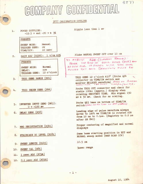
PULLED ONT AND SENSITIVITY
FULLY
TRIG SENS 12 o'clock 110 ( Probe 224
collector on TIME /CM switch and
m CAoPnAiCtoITr OHROLDOTFFYEwaPvOeIfNorTm
) PROBE TIME /cm
000.0
M8
00.00
M8
0.000
HE
000.0
ns
00.00
as
- 2-
August 10 , 1964
1
3T77 CALIBRATION OUTLINE January 8 , 1994
Stan Griffiths , WZNI 18955 S.W. Blanton Aloha , OR 97007
2
a point at which the trigger circuit oscillates and you will want to adjust this pot slightly ccw from this point . )
5 .
TRIG REGEN SENS ( R44 ) :
Connect test scope probe to front panel TRIG OUT connector and check for a stable display ( approximately 100 KHz ) while rotating the front panel RECOVERY TIME control . Signal amplitude 150 mv + or - 50 my .
1.
珠海优特UT-2000型微机防误操作系统用户使用说明手册
Ⅳ型与操作票专家系统珠海优特电力科技股份有限公司目录关于本用户使用说明书1.本说明书的目的 (1)2.本说明书的主要内容 (1)第一章概述1.1UT-2000Ⅳ型有三个安装版本……………………………………………1-11.2UT-2000Ⅳ型的主要功能与特点…………………………………………1-14.5 用户退出…………………………………………………………………4-34.6 去现场操作…………………………………………………………………4-44.7 操作结果回传……………………………………………………………4-44.8 结束系统运行……………………………………………………………4-4 第五章操作任务的开出与结束5.1 开操作票及操作票执行过程…………………………………………5-15.2 设置设备状态………………………………………………………5-15.3 开操作票………………………………………………………………5-15.4 开检修票………………………………………………………………5-55.5 操作票的结束……………………………………………………………5-6 第六章现场操作6.1 正常解锁操作………………………………………………………………6-16.2 电脑钥匙跳步操作…………………………………………………………6-46.3 应急解锁操作………………………………………………………………6-46.4 检修操作票的执行…………………………………………………………6-5 第七章安全日与地线管理7.1 安全日显示…………………………………………………………………7-111.1 历史操作票………………………………………………………………11-111.2 用户登录检索……………………………………………………………11-211.3 设备变位统计……………………………………………………………11-211.4 设备状态记录……………………………………………………………11-211.5 删除历史数据……………………………………………………………11-3关于本用户使用说明书1.本说明书的目的本说明书的目标读者为UT-2000Ⅳ型微机操作系统的直接用户,是系统安装、调试完成以后的使用说明书,主要说明UT-2000Ⅳ型系统的具体操作过程、系统维护以及注意事项。
UF2000系列壁挂式超声波流量计说明书_V3
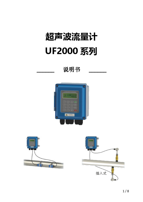
超声波流量计UF2000系列______说明书______概述UF2000系列超声波流量计应用于各种液体流量的长期在线测量,主机防等级达到IP67,传感器防护等级达到IP68,主机和传感器分别安装,主机可安装在室内、仪表盘、仪表柜,传感器安装在测量管道上,主机和传感器用超声波流量计专用电缆连接,即可实现流量测量,配接温度传感器可实现热量测量。
广泛应用于自来水、供暖、水利、冶金、化工、机械、能源等行业。
可以用做生产监测、水平衡调试、热网平衡调试、节能监测,是生产过程中重要的流量测量仪表。
特点-高精度测量,精度高达1%。
-主机防护等级达到IP67,传感器防护等级达到IP68-抗干扰强采用双平衡信号差分发射、接收电路,有效抵御变频器、电视塔、高压线等强干扰。
-传输距离远,组网快捷RS485支持无线组网,配接GPRS模块实现无线传输。
-支持温度测量配接温度传感器,可实现热量测量。
技术参数主机尺寸多种安装方式主机可选多种安装方式:1.选用专用挂件用于壁挂安装;2.选用导轨固定夹或者PCB安装支架,用于导轨安装;3.主机可安装在隔爆箱内。
壁挂安装示意图:导轨安装(导轨固定夹)示意图:D导轨安装(PCB安装支架)示意图:隔爆箱内安装示意图UF2000壁挂式安装类型夹装式:1安装无需断流,无压力损失2安装维修方便3配接夹装温度传感器,可以管外测量温度,实现热量测量插入式:1安装无需断流,无压力损失2长期运行稳定、可靠3配接插入式温度传感器,可实现热量测量回水管管段式:1安装需断管、断流2测量精度最高,长期运行稳定可靠3配接插入式温度传感器,可实现热量测量可选配的流量传感器根据不同的流体、管道条件及安装方式,可以选择不同的传感器。
(不同传感器的安装方式及特点参看测量组成图)回水管高温大型TL-1-HT DN300…DN6000-30…160℃97×54×53mm 插入式标准式TC-1DN80…DN6000-30…160℃190×80×55mm加长式TC-2DN80…DN6000-30…160℃335×80×55mm 管段式π型管段式G3DN15…DN25-30…160℃304不锈钢螺纹连接具体规格尺寸见管段式传感器规格表标准管道式G2DN32/DN40-30…160℃碳钢材质螺纹连接标准管段式G1DN50…DN6000-30…160℃碳钢材质法兰连接可选温度传感器选不同类型温度传感器,可实现热量测量可选配SD卡存储器SD卡数据存储器实现了超声波流量计测量数据的海量存储,解决了壁挂式流量计测量数据存储、读取及处理不便的问题,可完全替代人工抄表、无纸记录仪。
UT使用说明书
UT使用说明书目录项目页一、概述二、开箱检查三、安全操作准则四、电气符号五、外表结构六、显示符号七、按键功能及自动关机八、测量操作说明1.直流电压测量2.交流电压测量3.电阻测量4.二极管测量5.导通检测6.频率测量7.占空比测量8.直流电流测量9.交流电流测量3 3 4 6 7 8 9 11 11 12 13 14 15 16 17 18 1912项目页九、技术指标 1.一般规格 2.环境限制 3.电气规格 (1)直流电压 (2)交流电压 (3)电阻 (4)二极管测试 (5)导通测试 (6)频率 (7)占空比 (8)直流电流 (9)交流电流十、保养和维护 1.一般维护 2.电池安装或更换 20202121222224242525262627292929一、概述UT203、UT204是一种性能稳定,安全、可靠的3 3/4位交直流数字钳形表(以下简称钳表)系列。
整机电路设计以大规模集成电路双积分A/D转换器为核心,全量程的过载保护电路,独特的外观设计使之成为性能优越的专用电工仪表。
钳表可用于测量交直流电压、交直流电流、电阻、二极管、电路通断、频率等。
本使用说明书包括有关的安全信息和警告提示等,请仔细阅读有关内容并严格遵守所有的警告和注意事项。
警告在使用钳表之前,请仔细阅读有关“安全操作准则”二、开箱检查打开包装盒,取出仪表,请仔细检查下列项目是否缺少或损坏:1.使用说明书2.表笔3.带夹短测试线4.布包5.保用证一本一付一付一只一张如果发现任何一个项目缺少或损坏,请立即与您的供应商进行联系。
3三、安全操作准则请注意“警告标识及警告字句”。
警告表示对使用者构成危险、对仪表或被测设备可能造成损坏的情况或行动。
使用前应检查钳表和表笔,谨防任何损坏或不正常的现象。
如发现本钳表表笔、壳体绝缘已明显损坏以及液晶显示器无显示等,或者您认为本钳表已无法正常工作,请勿再使用本钳表。
后盖及电池盖没有盖好前严禁使用钳表,否则有电击危险。
Attero Tech unD4O 四路 Dante AES67 分输出接口用户手册说明书
unD4OFour Output Dante™/AES67 Break Out InterfaceUser ManualDate 8/27/2018Revision 02_dAttero Tech, LLC1315 Directors Row, Suite 107, Ft Wayne, IN 46808Phone 260-496-9668 • Fax 260-496-9879unD4OUser Manual IMPORTANT SAFETY INSTRUCTIONSThe symbols below are internationally accepted symbols that warn of potential hazards with electrical products.This symbol, wherever it appears, alerts you to the presence of un-insulated dangerous voltage inside the enclosure -- voltage that may be sufficient to constitute a risk of shock.This symbol, wherever it appears, alerts you to important operating and maintenance instructions in the accompanying literature. Please read the manual.1.Read these instructions.2.Keep these instructions.3.Heed all warnings.4.Follow all instructions.5.Do not use this apparatus near water.6.Clean only with a dry cloth.7.Do not block any ventilation openings. Install in accordance with the manufacturer's instructions.8.Do not install near any heat sources such as radiators, heat registers, stoves, or other apparatus (includingamplifiers) that produce heat.9.Protect the power cord (Ethernet cable) from being walked on or pinched particularly at plugs, conveniencereceptacles, and the point where they exit from the apparatus.10.Only use attachments/accessories specified by Attero Tech11.Unplug this apparatus during lightning storms.12.Refer all servicing to qualified service personnel. Servicing is required when the apparatus has been damaged inany way, such as power-supply cord or plug is damaged, liquid has been spilled or objects have fallen into the apparatus, the apparatus has been exposed to rain or moisture, does not operate normally, or has been dropped.13.If rack mounting, provide adequate ventilation. Equipment may be located above or below this apparatus butsome equipment (like large power amplifiers) may cause an unacceptable amount of hum, or may generate too much heat and degrade the performance of this apparatus.TO REDUCE THE RISK OF FIRE OR ELECTRIC SHOCK, DO NOT EXPOSE THIS APPARATUS TO RAIN OR MOISTURE.LIMITED FIVE YEAR WARRANTYThe equipment is warranted for five years from date of purchase from Attero Tech, LLC against defects in materials or workmanship. This warranty does not cover equipment which has been abused or damaged by careless handling or shipping. This warranty does not apply to used or demonstrator equipment. Should any defect develop, Attero Tech, LLC will, at our option, repair or replace any defective parts without charge for either parts or labor. If Attero Tech, LLC cannot correct the defect in the equipment, it will be replaced at no charge with a similar new item. Attero Tech, LLC will pay for the cost of returning your equipment to you. This warranty applies only to items returned to Attero Tech, LLC, shipping costs prepaid, within five years from the date of purchase. This Limited Warranty is governed by the laws of the State of Indiana. It states the entire liability of Attero Tech, LLC and the entire remedy of the purchaser for any breach of warranty as outlined above. NEITHER ATTERO TECH, LLC NOR ANYONE INVOLVED IN THE PRODUCTION OR DELIVERY OF THE EQUIPMENT SHALL BE LIABLE FOR ANY INDIRECT, SPECIAL, PUNITIVE, CONSEQUENTIAL, OR INCIDENTAL DAMAGES ARISING OUT OF THE USE OR INABILITY TO USE THIS EQUIPMENT EVEN IF ATTERO TECH, LLC HAS BEEN ADVISED OF THE POSSIBILITY OF SUCH DAMAGES. IN NO EVENT SHALL THE LIABILITY OF ATTERO TECH, LLC EXCEED THE PURCHASE PRICE OF ANY DEFECTIVE EQUIPMENT.This warranty gives you specific legal rights. You may have additional legal rights which vary from state to state.Note: This equipment has been tested and found to comply with the limits for a Class A digital device, pursuant to Part 15 of the FCC Rules and EN55022. These limits are designed to provide reasonable protection against harmful interference when the equipment is operated in a commercial environment. This equipment generates, uses, and can radiate radio frequency energy and, if not installed and used in accordance with the instruction manual, may cause harmful interference to radio communications. Operation of this equipment in a residential area is likely to cause harmful interference, in which case the user will be required to correct the interference at their own expenseThis symbol means the product must not be discarded as household waste, and should be delivered to an appropriate collection facility for recycling. Proper disposal and recycling helps protect natural resources, humanhealth and the environment. For more information on disposal and recycling of this product, contact yourlocal municipality, disposal service, or the business where you bought this product.Contents1 – Overview (4)1.1 – What’s in the Box (4)1.2 – Optional Extras (4)1.3 – Device Features (5)1.4 – Mounting and Installation (6)1.5 – Error Reporting (7)1.6 – Status LEDs (7)1.7 – Hardware Connections (8)1.7.1 – Balanced Output to an Unbalanced Input (8)1.7.2 – Balanced Output to a Balanced Input (9)2 – Device Configuration (10)2.1 – IP Address Setup (10)ARCHITECTS & ENGINEERING SPECIFICATION (i)Device Specifications (ii)1 – OverviewThe unD4O Dante™/AES67 audio interface is a cost effective 4 channel analog break-out box and is designed in a small flange-mount form factor for broad market application. Its size and I/O density make it easy to put Dante™ / AES67 connectivity wherever it’s needed – on a rack shelf, under a table or near the destination equipment – thereby eliminating costly and interference prone analog wiring and power supplies.The unD4O features four electronically balanced line-level outputs. All outputs can be used simultaneously and all audio channels are available separately from the Dante network.Connection to the Dante™/AES67 network is provided by a single Ethernet RJ45 connector on the back of the unit. The unD4O is PoE-enabled which allows the unD4O to be powered over its network cable from a suitable PoE source (IEEE 802.3af) or from a locally connected 24V DC power supply (sold separately ). This is particularly useful as the unD4O can then be mounted in remote location where access to a mains outlet would be limited or indeed, non-existent.Audinate’s Dante™ Controller or other 3rd party manufacturer's Dante™ routing software can be used to control the audio routing configuration of the device along with enabling of AES67 streams.1.1 – What’s in the BoxThe device comes supplied with the following:o (1) unD4Oo (4) 3-position Phoenix plug connectors1.2 – Optional ExtrasThe following are available as options for the unD4O and that may be ordered separately:o 24V DC Power Supply - P/N: 900-00175Figure 1 - unD4O Overview1.3 – Device Features24V DC Power InputDante™/AES67 PoE Connector ( requires CAT-5e or better Ethernet cabling)4 x Balanced audio outputsFront Panel LED Status IndicatorsRecovery reset switch*Note: The unD4O has a label on the flange of the metal housing that shows the devices MAC address. This is important for initial device identification as the last six digits make up part of the devices default network name that is shown when the device is detected by Dante™ Controller. The full MAC address is also given on the back of the unit.1.4 – Mounting and InstallationIt is recommended that the unit be secured to a flat surface with a screw through each mounting flange. Dimensions for mounting are show in the Error! Reference source not found.below. Use a No. 6 screw of a type and size that is applicable to the surface to which the device will be attached.Figure 2 - Mounting Informationo Attach the PoE + Data Dante™/AES67 INTERFACE port to a spare PoE-enabled port on a PoE switch using a CAT-5 cable. If a midspan injector is being used, connect a spare input port to the Dante network switch using a CAT-5 cable, and then connect the corresponding output port to the PoE + Data Dante INTERFACE of the unD4O.o Attach any audio sources that will be used to the inputs. The inputs are balanced so be sure to check what output type the source to be connected uses in order to find how to connect it correctly (see Hardware Connections section).If all steps are performed correctly, the power LED on the front should be lit. There may also be some activity on the Dante™/AES67 INTERFACE LED indicators. With no Dante™/AES67 network, both LEDs will remain off. If an active connection is made both LEDs will come on and if there is network activity, the yellow LED will then flash.*Note: All Attero Tech products are tested using UTP cabling and it is recommended that UTP cabling be used when installing them. STP cabling can be used for installation though care must be taken not introduce grounding issues into the system by doing so.1.5 – Error ReportingThe unD4O is equipped with error reporting features. Upon power up, the front panel power LED will briefly light red and then change to green if the device boots successfully. If the LED remains on solid red, this indicates a device failure. Additionally, the unD4O has three status indictor LEDs for showing various device states. The following figures show these states and associated descriptions.1.6 – Status LEDsThe front panel LED’s show the Dante™/AES67 diagnostic status. If network or audio problems persist, these LED’s may assist in identifying issues.The LED’s are POWER, SYS, ERR and SYNC and the color of each LED has different meanings. The tables below show the combination and what each combination means.ColorDescriptionAmberDevice Booting - If this LED stays amber, contact supportGreen Device Booted SuccessfullyColor DescriptionRed Dante™/AES67 Interface bootingGreen Dante™/AES67 Interface readyColor DescriptionYellow Capability is corruptedRedMemory stack overflowColorDescriptionAmber PTP currently syncingRedPTP error / no PTP sync / PTP disabledGreen PTP Slave, with PTP syncFlashingGreenPTP master / Identify*Identify (SYS, SYNC and ERR LED’sflashing)(Activated through the Identify function of Dante Controller)1.7 – Hardware ConnectionsThe unD4O provides balanced audio outputs for connectivity to external analog audio equipment. Refer to the following diagrams and instructions for connecting different types of audio devices to the outputs of the unD4O. Professional grade audio cabling is recommended to achieve the best audio performance throughout the system.1.7.1 – Balanced Output to an Unbalanced Input1.7.2 – Balanced Output to a Balanced Input2 – Device ConfigurationThe audio routing and enabling of Dante™/AES67 audio streams should be carried out using Audinate’s Dante™ Controller. This can be obtained from the Audinate website (). Instructions on how to use this software and about setting up routes on a Dante network can also be found on their website.*Note: When using Dante™ Controller, the unD4O will be shown using a default device name of “unD4O-######” where ‘######’ is the last six characters of the devices MAC address.2.1 – IP Address Setup******************************************************** IMPORTANT ****************************************************** Failure to correctly configure IP addresses will not allow an unD4O device to show up correctly in Dante™ Controller. The unD4O will appear but its device information won’t be visible. It’s output channels also won’t be visible and routing of audio to the device will not be possible.*****************************************************************************************************************************In order to configure an unD4O, both to set up internal parameters and also setup audio routing, the PC will need to be able to communicate with the devices over the network. While all Dante™ devices will be discovered regardless of the IP address setup on the PC, communication can only occur if the PC and the device have compatible IP addresses.By default, the unD4O is set to get a dynamic IP address. As with all Dante™/AES67 devices, if the unD4O does not find a DHCP server to retrieve an IP address from, it will give itself an local link address sometimes also known as an automatic private IP address (APIPA) instead. A local link IP address is always in the range 169.254.x.y.To ensure communication, the PC can either be set to get a dynamic IP address, or be given a static IP address in the range 169.254.x.y with a subnet mask of 255.255.0.0. The PC may require a restart if its IP address is changed for the change of IP to take effect.In some applications, IP addresses of devices may need to be set to something specific and that can be done once initial communication has been established. The uD4O does support static IP addresses but bear in mind however that if a static IP address is assigned to a device and that static IP address is in a different range to the IP it was previously using to communicate with the PC, the PC will then lose communication with the device when it’s rebooted until such time as the PC’s IP address is also changed to an IP in range of the devices now new IP address.Further information on IP setup for an audio system using Dante™ can be found in the FAQ’s on the Audinate website (https:///resources/faqs).ARCHITECTS & ENGINEERING SPECIFICATIONThe Dante™/AES67 interface unit shall provide four balanced analog outputs on the rear panel via 3-pin depluggable connectors for digital to analog conversion of up to four Dante digital audio network channels.The internal digital to analog signal conversion shall be performed at 24-bit resolution with a sampling frequency of 44.1kHz, 48kHz, 88.2 kHz or 96 kHz (configured by the system installer via software).The Dante™/AES67 interface unit shall receive power over the Ethernet cable from an IEEE 802.3af PoE compliant network switch, PoE midspan injector or a locally connected external 24V DC power supply.The Dante™/AES67 interface shall be compliant with the RoHS, WEEE and REACH directives.The Dante™/AES67 interface unit shall be Compliant with the EMI/EMC requirements for FCC and CE.The Dante™/AES67 interface unit shall be the Attero Tech unD4O.Device SpecificationsDante™/AES67 NetworkPhysical Level:Standard Ethernet Connector: Single RJ-45 Cable Quality: CAT-5e or better Transmission Speed:100 Mbps Supported Sample Rates44.1kHz48kHz 88.2 kHz 96 kHzMinimum Dante NetworkLatency1msPower RequirementsPoE802.3af PoE PD compliant Class 0 Power Consumption 4 W Max. Cable Quality:CAT-5e or betterPhysical DimensionsWidth 6.45" Height 1.06" Depth 3.45" Weight0.8 lbsProduct ComplianceFCC CFR 47 Parts 15B ICES-003 CE (EN55022) RoHS REACHAudio Outputs Output Type:Four balanced line level with automatic muting on loss of Dante signal on 3-pin Depluggable Phoenix Output Impedance 200 Ohms Balanced Maximum Output Levels:+20dBu BalancedAudio Output PerformanceDynamic Range: 100 dBTHD+N: <0.02% @ 1kHz, input signal 3dB below maximum Frequency Response20Hz – 20kHz, +/- 1dB。
Omega LTU2000系列铃铛式水位传感器说明书

e-mail:**************For latest product manuals: LTU2000 SERIESTuning Fork Point Level SwitchesShop online at User’s Guide***********************Servicing North America:U.S.A. Omega Engineering, Inc.Headquarters: Toll-Free: 1-800-826-6342 (USA & Canada only)Customer Service: 1-800-622-2378 (USA & Canada only)Engineering Service: 1-800-872-9436 (USA & Canada only)Tel: (203) 359-1660 Fax: (203) 359-7700e-mail:**************For Other Locations Visit /worldwideThe information contained in this document is believed to be correct, but OMEGA accepts no liability for any errors it contains, and reserves the right to alter specifications without notice.TMContentsIntroduction (5)Models (6)Models and Dimensions (7)Wiring Diagram (8)LTUP and LTUR Status Guide (11)LTUM Status Guide (12)Installation (13)Handling (14)Technical Specifications (15)Trouble Shooting (19)Notes (20)0304IntroductionOmega's LTU-2000 Series use a piezo-electric crystal that enables the switch to vibrate at a fixed pre-defined resonant frequency. When the tuning fork is submerged in the medium the frequency at which the switch is vibrating, changes. This change is detected by the electronics and is converted into a switch output (either relay or PNP/NPN depending on the model).The red LED in the housing stays blinking when the is in contact with the product. The same light stays on continuously when there is no contact with the product, giving a positive indication at all times that the LTU-2000 is working.All models are made with 316 Stainless Steel and are available with ECTFE or epoxy coatings and hygienic fittings for sanitary applications. Standard versions can operate at temperatures up to 80ºC (176ºF) and higher temperature versions can operate at temperatures up to 120ºC (248ºF). All models (except the mini-versions) have adjustable time delay adjustment of 1, 5, 10 or 20 seconds and also have a Wet/Dry selection for both High and Low level application requirements.unit’s LTU-2000Unaffected by variations in density, conductivity, dielectric constant or viscosity Unaffected by foam, tank agitation or vibrationAvailable in Threaded, Sanitary and Flanged connectionsAvailable with customized length options to best suit your application All 316SS body and wetted parts, coating when necessary Adjustable response time (from 1 to 20 seconds)Relay and T ransistor outputs availableECTFE LTU-2000 Series:Point Level SwitchFeaturesModelsTM LTUM1-DC LTUM2-ACLTURNYLON HOUSINGLTURALUMINUM HOUSING05Models and Dimensions06Mounting Options for LTU-2000Insertion LengthProcess ConnectionsMTHTLTUM126m m130m m130mm118mm89mm76m m89mm80mmStandardExtended LengthTC StandardLTUTC StandardLTUMExtended necks for medium (up to 100ºC) and high temperature (up to 120ºC)temperature 100m m50m mExtended Necks for High T emperatureNylon AluminumAluminumWiring Diagram07TMWet/DryLTUR - Universal Power Supply Nylon Housing12 - Power Supply (-)3 - PNP/NPN Outputor +24v/0v (Max 500mA) 4 - - Power Supply (+)GroundLTUP - Housing( 1 ; 5 ; 10 ; 20 sec. )The different key positions indicate the time delay in seconds.Time Delay GuideLTUP - with M12 Connector12 - Power Supply (-)3 - PNP/NPN Outputor +24v/0v (Max 500mA) 4 - - Power Supply (+)GroundLTUR - with M12 ConnectorDC: 18...36Vdc(I) < 6mA12 - Power Supply (-)3 - Power Supply (+)4 - NC Contact5 - Common 6-NO Contact- Power Supply (L)AC ( )DC ( )}}12 - Power Supply (-)3 - NO Contact 4 - NC Contact 5 - Common- Power Supply (L) or (+)08Wiring DiagramLTUR - Universal Power Supply Small Aluminum HousingLTUR - with M12 connector12 - Power Supply (-)3 - Power Supply (+)4 - NO Contact5 - NO Common6 - NC Contact7 - NC Common- Power Supply (L)AC ( )DC ( )}}12-Power Supply (-)3 - NO Contact 4 - NC Contact 5 - Common-Power Supply (L) or (+)12-Power Supply (-)3 - Power Supply (+)4 - NC Contact5 - Common6 - NO Contact-Power Supply (L)AC ( )DC ( )}}LTUR - Universal Power Supply Large Aluminum HousingTM T o avoid burning the unit, make sure that the load has beeninstalled in series with the LTUM before powering it up.Wiring Diagram09TM LTUP and LTUR Status GuideFor LTUP / DCFor LTUR (Universal Power Supply)10LTUM Status Guide1112InstallationThe can be installed at any angle of the pipe or vessel to detect the presence of liquids.Verify that the forks are inserted into the medium until the proper point within the vessel and that they stay clear from the inside walls (Fig. 1 and 2).LTU For proper installation of the use the mark as a reference for correctly positioning the forks. It is recommended that the correct orientation be used to avoid build up between the forks (Fig. 4).LTU Confirm that the wire connections are correct and that the available power supply is compatible with the LTU unit.Verify that the operating pressure and temperature of the process corresponds to the operating parameters of the unit.LTU Ensure that the conduit is facing downward and makes a U-turn on the bottom of the cable to avoid moisture from entering the housing enclosure (Fig.3).Side View(Fig.3)TM13HandlingPeriodic visual inspection of the is required to check for corrosion or deposit build-up. If deposits are found, clean the sensor to ensure optimum performance.LTU The should not be dropped or suffer any impact or fall that could damage the electronics, coating or the forks of the probe (Fig. 4 and 5).LTU Seal the thread with T eflon tape before installation (Fig. 1).Do not thread the unit into the vessel, or turn it, by the housing (Fig. 2).Use the correct tools during the installation of the (Fig. 3).LTU When cleaning the Forks use a soft brush to ensure that the coating or polishing is not damaged or scratched.Do not alter or bend the shape of the forks ( Fig. 6).Fig. 5Fig. 6Fig. 4Fig. 2Fig. 1T echnical Specifications14LTUPNylon EnclosureTM15TMT echnical SpecificationsNylon Enclosure Aluminum EnclosureAluminum Enclosure16LTUM1LTUM1T echnical SpecificationsTM17LTUM2LTUM2Technical SpecificationsTM Trouble ShootingOMEGA’s policy is to make running changes, not model changes, whenever an improvement is possible. This affordsour customers the latest in technology and engineering.OMEGA is a trademark of OMEGA ENGINEERING, INC.© Copyright 2018 OMEGA ENGINEERING, INC. All rights reserved. T his document may not be copied, photocopied, reproduced, translated, or reduced to any electronic medium or machine-readable form, in whole or in part, without the prior written consent of OMEGA ENGINEERING, INC.FOR WARRANTY RETURNS, please have thefollowing information available BEFORE contacting OMEGA:1. P urchase Order number under which the productwas PURCHASED,2. M odel and serial number of the product underwarranty, and3. Repair instructions and/or specific problemsrelative to the product.FOR NON-WARRANTY REPAIRS, consult OMEGA for current repair charges. Havethe following information available BEFORE contacting OMEGA:1. Purchase Order number to cover the COST of the repair,2. Model and serial number of the product, and 3. Repair instructions and/or specific problems relative to the product.RETURN REQUESTS/INQUIRIESDirect all warranty and repair requests/inquiries to the OMEGA Customer Service Department. BEFORE RET URNING ANY PRODUCT (S) T O OMEGA, PURCHASER MUST OBT AIN AN AUT HORIZED RET URN (AR) NUMBER FROM OMEGA’S CUST OMER SERVICE DEPART MENT (IN ORDER T O AVOID PROCESSING DELAYS). The assigned AR number should then be marked on the outside of the return package and on any correspondence.The purchaser is responsible for shipping charges, freight, insurance and proper packaging to prevent breakage in transit.WARRANTY/DISCLAIMEROMEGA ENGINEERING, INC. warrants this unit to be free of defects in materials and workmanship for a period of 13 months from date of purchase. OMEGA’s WARRANTY adds an additional one (1) month grace period to the normal one (1) year product warranty to cover handling and shipping time. This ensures that OMEGA’s customers receive maximum coverage on each product.If the unit malfunctions, it must be returned to the factory for evaluation. OMEGA’s Customer Service Department will issue an Authorized Return (AR) number immediately upon phone or written request. Upon examination by OMEGA, if the unit is found to be defective, it will be repaired or replaced at no charge. OMEGA’s WARRANT Y does not apply to defects resulting from any action of the purchaser, including but not limited to mishandling, improper interfacing, operation outside of design limits, improper repair, or unauthorized modification. T his WARRANT Y is VOID if the unit shows evidence of having been tampered with or shows evidence of having been damaged as a result of excessive corrosion; or current, heat, moisture or vibration; improper specification; misapplication; misuse or other operating conditions outside of OMEGA’s control. Components in which wear is not warranted, include but are not limited to contact points, fuses, and triacs.OMEGA is pleased to offer suggestions on the use of its various products. However, OMEGA neither assumes responsibility for any omissions or errors nor assumes liability for any damages that result from the use of its products in accordance with information provided by OMEGA, either verbal or written. OMEGA warrants only that the parts manufactured by the company will be as specified and free of defects. OMEGA MAKES NO OTHER WARRANTIES OR REPRESENTATIONS OF ANY KIND WHATSOEVER, EXPRESSED OR IMPLIED, EXCEPT THAT OF TITLE, AND ALL IMPLIED W ARRANTIES INCLUDING ANY W ARRANTY OF MERCHANTABILITY AND FITNESS FOR A PARTICULAR PURPOSE ARE HEREBY DISCLAIMED. LIMITATION OF LIABILITY: The remedies of purchaser set forth herein are exclusive, and the total liability of OMEGA with respect to this order, whether based on contract, warranty, negligence, indemnification, strict liability or otherwise, shall not exceed the purchase price of the component upon which liability is based. In no event shall OMEGA be liable for consequential, incidental or special damages.CONDITIONS: Equipment sold by OMEGA is not intended to be used, nor shall it be used: (1) as a “Basic Component” under 10 CFR 21 (NRC), used in or with any nuclear installation or activity; or (2) in medical applications or used on humans. Should any Product(s) be used in or with any nuclear installation or activity, medical application, used on humans, or misused in any way, OMEGA assumes no responsibility as set forth in our basic WARRANTY /DISCLAIMER language, and, additionally, purchaser will indemnify OMEGA and hold OMEGA harmless from any liability or damage whatsoever arising out of the use of theProduct(s) in such a manner.Where Do I Find Everything I Need forProcess Measurement and Control?OMEGA…Of Course!Shop online at TEMPERATUREM U Thermocouple, RTD & Thermistor Probes, Connectors, Panels & AssembliesM U Wire: Thermocouple, RTD & ThermistorM U Calibrators & Ice Point ReferencesM U Recorders, Controllers & Process MonitorsM U Infrared PyrometersPRESSURE, STRAIN AND FORCEM U Transducers & Strain GagesM U Load Cells & Pressure GagesM U Displacement TransducersM U Instrumentation & AccessoriesFLOW/LEVELM U Rotameters, Gas Mass Flowmeters & Flow ComputersM U Air Velocity IndicatorsM U Turbine/Paddlewheel SystemsM U Totalizers & Batch ControllerspH/CONDUCTIVITYM U pH Electrodes, Testers & AccessoriesM U Benchtop/Laboratory MetersM U Controllers, Calibrators, Simulators & PumpsM U Industrial pH & Conductivity EquipmentDATA ACQUISITIONM U Communications-Based Acquisition SystemsM U Data Logging SystemsM U Wireless Sensors, Transmitters, & ReceiversM U Signal ConditionersM U Data Acquisition SoftwareHEATERSM U Heating CableM U Cartridge & Strip HeatersM U Immersion & Band HeatersM U Flexible HeatersM U Laboratory HeatersENVIRONMENTALMONITORING AND CONTROLM U Metering & Control InstrumentationM U RefractometersM U Pumps & TubingM U Air, Soil & Water MonitorsM U Industrial Water & Wastewater TreatmentM U pH, Conductivity & Dissolved Oxygen InstrumentsM3991/1218。
机防误操作系统产品简介
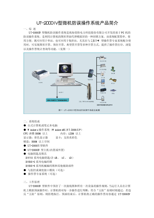
UT-2000IV型微机防误操作系统产品简介 一、综述UT-2000IV型微机防误操作系统是珠海优特电力科技股份有限公司开发的基于PC机的防误操作系统,是利用计算机的图形界面代替模拟屏的一种闭锁方案。
该系统配置简单、使用方便,既可应用于单站,也可应用于集控站。
尤其在与ZJXT-W型操作票专家系统配合使用时,可实现图形开票、预存开票、典型票开票等多种开票方式,提供了操作票打印、浏览以及操作票统计查询等功能。
(见图一)二、系统组成●台式计算机或笔记本电脑● Windows操作系统(Windows9X/NT/2000/XP)CPU:奔腾500M以上内存:128M以上显示器:彩色显示器显卡:支持真彩色硬盘:500M以上空间● UT-2000Ⅳ型软件● UT-2000IV型主机(内置或外置)●电脑钥匙及锁具DNYS系列电脑钥匙(含1B、 1C、 1D)DNBS-2系列电编码锁DNBS-3系列机械编码锁和其他辅助部件●与监控或调度接口模块(可选)● 操作票专家系统(可选)三、工作原理UT-2000IV型软件中预存了一次接线图和所有一次设备的操作规则,当运行人员在计算机上模拟预演操作时,计算机将对每一步操作进行判断,符合“五防”原则时则通过,若违反“五防”原则,则拒绝执行。
预演结束后,计算机将正确的操作票内容通过UT-2000IV型主机传送到电脑钥匙中,运行人员便可持电脑钥匙到现场操作。
操作时,电脑钥匙按照预演正确的顺序显示当前操作项,运行人员依照电脑钥匙的提示将电脑钥匙插入相应设备的编码锁内,若设备与电脑钥匙提示的设备一致,则电脑钥匙开放其闭锁机构,允许进行断路器、电动隔离开关操作或打开机械编码锁进行倒闸操作;若设备与电脑钥匙提示的设备不一致,则电脑钥匙不允许解锁,并发出持续的报警声来提醒操作人员,从而达到强制闭锁功能。
操作完一项后,电脑钥匙将自动显示下一项操作内容,所有操作结束后电脑钥匙将会提示将操作结果回传到电脑,从而使设备状态与现场的设备状态保持一致,达到与现场设备自动对位的目的。
UTD2000L数字存储示波器实时监控软件用户手册V1.6
数字存储示波器 通讯控制软件 使用手册及安装说明1、优利德科技(中国)有限公司版权所有。
2、本公司的产品受已获准及尚在审批的中华人民共和国专利的保护。
3、本手册提供的信息取代以往出版的所有资料。
4、本公司保留改变规格及价格的权利。
注:UNI-T是优利德科技(中国)有限公司的注册商标。
目录第一章数字存储示波器通讯控制软件的安装 (4)第一节硬件需求 (4)第二节数字存储示波器通讯控制软件的安装步骤 (4)第三节数字存储示波器通讯控制软件驱动程序安装 (8)第四节数字存储示波器通讯控制软件的启动 (12)第二章初步了解数字存储示波器通讯控制软件结构 (14)第一节数字存储示波器通讯控制软件面板简介 (14)第二节主菜单说明 (15)第三章数字存储示波器通讯控制软件操作指南 (16)USB接口通讯控制方式 (16)第四章系统提示及故障排除 (19)第一节系统提示信息 (19)第二节故障排除 (19)第一章数字存储示波器通讯控制软件的安装第一节硬件需求设备需求最小需求示波器 UTD2000L数字存储示波器2000/XP/Vista系统,128兆内存,16倍速光驱计算机 Windows或更好(Vista系统参见其对应硬件需求),分辨率1024*768或更好。
连接线两端USB/HOST接口线第二节数字存储示波器通讯控制软件的安装步骤当你购买UTD2000L数字存储示波器(以下简称示波器)时会随机配置数字存储示波器通讯控制软件(数字存储示波器通讯控制软件在随机附带的光盘中)。
软件名称:UTD2000L数字存储示波器实时监控软件。
安装步骤:第一步:把随机附带的光盘插入计算机的光驱中,待读取随机附带光盘中的内容,找到示波器通讯控制软件(图1-1)图1-1注:1、从网站上下载的数字存储示波器通讯控制软件的安装包,需解压后才能使用。
2、数字存储示波器通讯控制软件支持Windows 2000、Windows XP、Vista操作系统。
特菲尔操作手册
前言本操作手册适用于TF200﹑TF2000系列火灾报警器的使用操作指导,使用操作前请仔细阅读,并妥善保管,以备查用。
TF200是单回路火灾报警控制器,不具有总线手动操作按键,若工程需要可机外扩展,其使用和操作方法与TF2000完全相同。
TF2000为24回路火灾报警控制器。
TF2000区域集中兼容型系列自动火灾报警控制器,满足中华人民共和国标准GB4717-2005﹑GB16806-2006的规定和要求。
采用模块化结构﹑32位单片机集成电路﹑SMT工艺,产品的可靠性﹑灵活性﹑实用性得到极大提高,是一款极具市场竞争力的产品。
●320×240TFT真彩液晶显示人机界面。
●支持U盘上传下载数据.●支持PC在线编程。
●计算机传送编程数据。
●拷贝历史记录等操作,使编程﹑操作更具有人性化。
●可连接CRT图形显示终端。
●具备报警﹑联动﹑监管﹑广播﹑电话等功能。
●可以广泛应用于化工﹑钢铁﹑能源﹑工矿企业﹑饭店﹑宾馆﹑写字楼﹑商厦﹑学校﹑住宅等场所。
目录第1章操作 ..................................................................................................... 错误!未定义书签。
面板操作 .................................................................................................... 错误!未定义书签。
开机 ............................................................................................................ 错误!未定义书签。
系统自检 .................................................................................................... 错误!未定义书签。
UNT-WF-2000箱变测控装置使用说明书(V3.3)总结

5)零序过压保护
6)零序过流保护
2.5
支持15路有源接点输入和4路开出
2.6
两路百兆光口,一路以太网口和一路RS485口
2.7
PLC功能
事故记录功能
SOE功能
通讯对时功能
显示功能
注:显示模块主要作为初装调试用,如业主需要显示功能,在订货时需特别注明
第三章
3.1
装置面板和端子布置
血■运行以太网串口 报警跳闸电源
6.1默认显示特殊图7
6.2菜单结构7
6.3复归8
6.4电量8
6.5非电量8
6.5.1开关量9
6.5.2直流量9
6.5.3温度9
6.6SOE查看10
6.7事件记录10
6.8功能设置11
6.8.1保护设置11
6.8.2PLC设置12
6.8.3网络设置13
6.8.4通讯设置14
6.9参数设置15
6.9.1系数设置15
6.9.2PT/CT设置15
6.9.3时间设置16
6.10清零电度16
第七章 装置参数16
第八章 服务承诺18
附录一:典型接线图19
附录二:PLC逻辑20
第一章 装置简介
概述
UNT-WF-2000风电场箱变综合测控装置是保定市尤耐特电气有限公司联合 风电控制专家,总结多年的测控经验, 研究风电场的特点, 结合现有箱变的设计、 应用方案的基础上, 为适应风电场恶劣环境的测控发展, 针对目前风电场中测控 方案的不足、巡回检测时间长等不利因素而研发的一款集信号测量、 控制、通讯、 保护于一体的智能装置。
UNT-WF-200风电场箱变综合测控装置是一款体积小巧、配置灵活、功能完 善、能适应恶劣环境的数据采集、 控制及保护装置。 它适用于风电场中布局分散 的风机升压箱变低压侧的测量、 控制和保护, 可以与其他装置组成光纤环网将采 集到的数据上传到后台监控系统, 为整个风电场风机侧运行的监控提供准确、 实 时的数据支持。
- 1、下载文档前请自行甄别文档内容的完整性,平台不提供额外的编辑、内容补充、找答案等附加服务。
- 2、"仅部分预览"的文档,不可在线预览部分如存在完整性等问题,可反馈申请退款(可完整预览的文档不适用该条件!)。
- 3、如文档侵犯您的权益,请联系客服反馈,我们会尽快为您处理(人工客服工作时间:9:00-18:30)。
启动…………………………………………………………………4-1
4.2
用户登录和退出…………………………………………………………4-2
4.3
用户退出…………………………………………………………………4-2
4.2
结束系统运行……………………………………………………………4-3
第五章开操作票
5.1
开操作票及操作票执行过程……………………………………5-1
6.1.2
改变接线图中的标签……………………………………………………6-1
6.1.3
改变设备编号……………………………………………………………6-1
6.2
改变色设备的操作条件…………………………………………………6-2
6.3
改变设备名称……………………………………………………………6-5
6.4
改变操作术语的形成方式………………………………………………6-5
4----红外线收发管,用于与主机交换数据。
5----开锁按钮:按压后带动解锁杆顺时针旋转,用以打开机械编码锁。
6----喇叭发声孔。
7----电源开关:用于关闭或打开电脑钥匙电源开关、功能按键等。
8----座充充电电极插入孔。
9----四个指示图标。
10---高容量锂离子电池。
11---点阵液晶显示屏:用于显示操作内容等汉字信息。
计算机与现场设备无电缆连接,断路器通过电编码锁闭锁,隔离开关、接地刀闸等其它设备采用机械编码锁闭锁,电动设备可闭锁监控系统,大大简化了现场安装和维护工作量。所有机械编码锁、电编码锁均由一把电脑钥匙操作,每一步操作电脑钥匙上都有详细提示。
①本文的内容为UT-2000Ⅳ型装置使用说明,如用户同时选购“操作票专家系统”,则相关操作请参考《操作票专家系统用户使用说明书》。
②如果UT-2000Ⅳ型装置与DNBS-Ⅱ、Ⅲ,UT-2000Ⅱ、Ⅲ,UT-2000B、C、D系列产品、监控系统配套使用,则相关配置、操作请参考各配套产品的相关说明书部分。
③UT-2000Ⅳ型装置全面兼容DNBS-Ⅳ型微机防误闭锁装置。
第二章闭锁原理及实现方法
2.1 UT-2000Ⅳ型装置的基本组成
机械编码锁………………………………………………………………2-6
2.7
设备闭锁…………………………………………………………………2-8
2.7.1
设备闭锁的实现方法…………………………………………………2-8
2.7.2
断路器闭锁……………………………………………………………2-8
2.7.3
电动隔离开关、接地刀闸的闭锁………………………………………2-8
10.3
探头自检及锁头更换……………………………………………………10-1
10.4
锁编码……………………………………………………………………10-2
10.5
锁编码的编码校验………………………………………………………10-2
10.6
机械编码锁,电编码锁故障及更换……………………………………10-2
第一章概述
·一次接收操作内容:≤512帧
·允许通过操作回路电流:5mA~5A
·抗电强度:≥1500V
·抗射频干扰强度:≤50db(uV/m)
·抗电源端子传输干扰强度:≤70db(uV)
·抗冲击强度:≥6g
·外形尺寸:147×71×31 mm
·平均无故障时间(MTBF)100000次
·操作回路额定电压:≤220V交、直流
UT-2000Ⅳ型微机防误装置
用户使用说明书
(Version 3.0)
珠海优特电力产品配套有限公司
2001年3月
第一章概述…………………………………………………………………………1-1
第二章闭锁原理及实现方法…………………………………………………………2-1
2.1
UT-2000Ⅳ型装置的基本组成……………………………………………2-1
UT-2000Ⅳ型微机防误闭锁装置(以下简称UT-2000Ⅳ型装置),根据电力系统对倒闸操作的“五防”要求和现场设备的状态,按照“电力”五防规则进行判断、推理,开出完全实用的倒闸操作票;然后用户将传输有正确操作票的电脑钥匙拿到现场对断路器、隔离开关、接地刀闸、临时接地线、网门等设备进行倒闸操作。它是用于防止电力系统电气误操作事故的一种新型闭锁装置。
2.3台式计算机通讯适配器
UT-2000Ⅳ型装置使用的TADP-1B通讯适配器安装在台式计算机主机的光驱/大软驱位置,在内部有通讯电缆与计算机的串口连接。模拟预演形成的操作票也通过装在台式计算机中的TADP-1B通讯适配器的传输口传输到电脑钥匙。
图2-3:UT-2000Ⅳ型结构图
2.4 DNYS-1C型电脑钥匙
注:“环境温度”项不包含语音
2.5电编码锁
2.5.1电编码锁闭锁对象
电编码锁用于断路器、电动隔离开关和电动接地刀闸的电气操作回路的闭锁。
2.5.2电编码锁闭锁原理
电编码锁在电气原理上相当于一个常开接点,通常被串入到相应的电气操作回路中。由于原有的操作回路被切断,因此操作前必须先通过电脑钥匙解锁。
正常操作时,先将电脑钥匙插入电编码锁中,如操作设备的编号和电脑钥匙显示的编号一致,则电脑钥匙内部接通操作回路,闭锁解除,允许操作。合、分操作后,电脑钥匙检测到有操作电流流过,即认为操作结束,接着显示下一项。
3.1
运行环境……………………………………………………………………3-1
3.2
系统安装……………………………………………………………………3-1
3.3
数据备份与恢复…………………………………………………………3-1
3.4
TADP-1B通讯适配器的安装……………………………………………3-3
第四章启动本系统和结束运行
特别说明:UT-2000Ⅳ型装置(WINDOWS 95/98/NT版)不支持数显电脑钥匙(DNBS-1A型)
2.2 UT-2000Ⅳ型装置的基本原理
UT-2000Ⅳ型装置以微型计算机+TADP-1B通讯适配器为核心设备,在本系统软件中预先编写了发电厂/变电站电气一次系统接线模拟图和所有设备的操作规则;系统可通过监控系统或模拟屏得到现场的设备实际状态(系统本身也具备记忆功能),当运行人员在计算机模拟图上模拟预演时,计算机就根据预先编写好的规则对每一项操作进行判断,拒绝执行违反“五防”原则的操作,预演结束后可通过TADP-1B通讯适配器的传输口将所预演正确的操作内容传输到电脑钥匙中,然后运行人员就可以拿着电脑钥匙到现场倒闸操作。
注:DNYS-1C详细说明请参阅《DNYS-1C型电脑钥匙使用说明书260000》
2.4.1 DNYS-1C型电脑钥匙、外形图及各部件功用
图1DNYS-1C型电脑钥匙外形图
图1中:
1----传输定位销:电编码锁导电电极。
2----探头:用于检测锁编号,有10位机械探头和12位光电探头2种。
3----解锁杆:用于开机械编码锁,兼电编码锁导电极。
该装置有以下特点:
1.闭锁功能强
不但能对断路器、隔离开关、接地刀闸进行闭锁,还能对临时接地线、网门等进行闭锁。除满足基本的“五防”闭锁功能外,还可实现旁路母线充电、倒母线操作、线路侧验电、就地或远方操作等复杂闭锁功能。
2.配置灵活方便
既可单独使用、也可和操作票专家系统,UT2000-II、III,UT-2000B、C、D系列装置,监控系统等系统配套使用。并可实现与各套设备之间实现信息共享、相互闭锁。
2.4.3 DNYS-1C型电脑钥匙技术参数
·环境温度:-20℃ ~+50℃
·环境相对湿度 日平均≤95%,月平均≤90%
·电源:3.6V,600mAh(或更高容量),高容量可充电锂离子电池
·静态电流: ≤20mA
开锁时最大电流:≤300mA
·识别编码锁个数:
机械探头:≤1000把
光电探头:≤4090把
3.多站、多图、多任务并行操作
允许一机多站、一站多图操作和多任务并行操作;在一站多图和多站多图的各接线图间可任意切换,方便显示和操作。
4.外围设备接口
本系统可与监控系统,DNBS-Ⅱ、Ⅲ,UT-2000Ⅱ、Ⅲ,UT-2000B、C、D系列设备进行通讯,以保证本系统一次设备与设备的实际状态保持一致。
5.安装、维护、使用方便
第九章现场操作
9.1
现场闭锁设备的安装和电脑钥匙的设置、自学……………………………9-1
9.2
现场设备操作……………………………………………………………9-1
9.3
操作结束…………………………………………………………………9-4
9.4
多任务并行操作…………………………………………………………9-5
9.5
2.7.4
手动隔离开关、接地刀闸、网门的闭锁………………………………2-8
2.7.5
临时接地线的闭锁……………………………………………………2-9
2.7.6
防止“空程序”…………………………………………………………2-10
2.7.7
线路侧验电………………………………………………………………2-11
第三章运行环境、系统安装和数据备份
12---插充、程序升级等数据接口。
2.4.2 DNYS-1C型电脑钥匙主要性能
1)能够正确无误地接收工控机传送的操作票。
2)能够记忆存储操作票。关闭电源时,内容不丢失。
3)具有清票、自学、自检、记忆、锁编码检查、中止当前的操作票、跳步、浏览当前操作票、实时时钟、电池电量检测、操作票追忆、自诊断、把记忆的操作票传输给上位机等功能。
2.2
UT-2000Ⅳ型装置的基本原理……………………………………………2-1
2.3
台式计算机及通讯适配器………………………………………………2-1
