MMC40193中文资料
CD系列芯片资料(全)
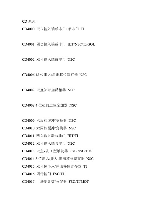
CD系列:CD4000 双3输入端或非门+单非门TICD4001 四2输入端或非门HIT/NSC/TI/GOL CD4002 双4输入端或非门NSCCD4006 18位串入/串出移位寄存器NSCCD4007 双互补对加反相器NSCCD4008 4位超前进位全加器NSCCD4009 六反相缓冲/变换器NSCCD4010 六同相缓冲/变换器NSCCD4011 四2输入端与非门HIT/TICD4012 双4输入端与非门NSCCD4013 双主-从D型触发器FSC/NSC/TOS CD4014 8位串入/并入-串出移位寄存器NSC CD4015 双4位串入/并出移位寄存器TICD4016 四传输门FSC/TICD4017 十进制计数/分配器FSC/TI/MOTCD4018 可预制1/N计数器NSC/MOTCD4019 四与或选择器PHICD4020 14级串行二进制计数/分频器FSCCD4021 08位串入/并入-串出移位寄存器PHI/NSCCD4022 八进制计数/分配器NSC/MOTCD4023 三3输入端与非门NSC/MOT/TICD4024 7级二进制串行计数/分频器NSC/MOT/TICD4025 三3输入端或非门NSC/MOT/TICD4026 十进制计数/7段译码器NSC/MOT/TICD4027 双J-K触发器NSC/MOT/TICD4028 BCD码十进制译码器NSC/MOT/TICD4029 可预置可逆计数器NSC/MOT/TICD4030 四异或门NSC/MOT/TI/GOLCD4031 64位串入/串出移位存储器NSC/MOT/TICD4032 三串行加法器NSC/TICD4033 十进制计数/7段译码器NSC/TICD4034 8位通用总线寄存器NSC/MOT/TICD4035 4位并入/串入-并出/串出移位寄存NSC/MOT/TI CD4038 三串行加法器NSC/TICD4040 12级二进制串行计数/分频器NSC/MOT/TICD4041 四同相/反相缓冲器NSC/MOT/TICD4042 四锁存D型触发器NSC/MOT/TICD4043 4三态R-S锁存触发器("1"触发) NSC/MOT/TI CD4044 四三态R-S锁存触发器("0"触发) NSC/MOT/TI CD4046 锁相环NSC/MOT/TI/PHICD4047 无稳态/单稳态多谐振荡器NSC/MOT/TICD4048 4输入端可扩展多功能门NSC/HIT/TICD4049 六反相缓冲/变换器NSC/HIT/TICD4050 六同相缓冲/变换器NSC/MOT/TICD4051 八选一模拟开关NSC/MOT/TICD4052 双4选1模拟开关NSC/MOT/TICD4053 三组二路模拟开关NSC/MOT/TICD4054 液晶显示驱动器NSC/HIT/TICD4055 BCD-7段译码/液晶驱动器NSC/HIT/TICD4056 液晶显示驱动器NSC/HIT/TICD4059 “N”分频计数器NSC/TICD4060 14级二进制串行计数/分频器NSC/TI/MOT CD4063 四位数字比较器NSC/HIT/TICD4066 四传输门NSC/TI/MOTCD4067 16选1模拟开关NSC/TICD4068 八输入端与非门/与门NSC/HIT/TICD4069 六反相器NSC/HIT/TICD4070 四异或门NSC/HIT/TICD4071 四2输入端或门NSC/TICD4072 双4输入端或门NSC/TICD4073 三3输入端与门NSC/TICD4075 三3输入端或门NSC/TICD4076 四D寄存器CD4077 四2输入端异或非门HIT CD4078 8输入端或非门/或门CD4081 四2输入端与门NSC/HIT/TI CD4082 双4输入端与门NSC/HIT/TI CD4085 双2路2输入端与或非门CD4086 四2输入端可扩展与或非门CD4089 二进制比例乘法器CD4093 四2输入端施密特触发器NSC/MOT/ST CD4094 8位移位存储总线寄存器NSC/TI/PHI CD4095 3输入端J-K触发器CD4096 3输入端J-K触发器CD4097 双路八选一模拟开关CD4098 双单稳态触发器NSC/MOT/TICD4099 8位可寻址锁存器NSC/MOT/STCD40100 32位左/右移位寄存器CD40101 9位奇偶较验器CD40102 8位可预置同步BCD减法计数器CD40103 8位可预置同步二进制减法计数器CD40104 4位双向移位寄存器CD40105 先入先出FI-FD寄存器CD40106 六施密特触发器NSCTICD40107 双2输入端与非缓冲/驱动器HARTI CD40108 4字×4位多通道寄存器CD40109 四低-高电平位移器CD40110 十进制加/减,计数,锁存,译码驱动ST CD40147 10-4线编码器NSCMOTCD40160 可预置BCD加计数器NSCMOTCD40161 可预置4位二进制加计数器NSCMOTCD40162 BCD加法计数器NSCMOTCD40163 4位二进制同步计数器NSCMOTCD40174 六锁存D型触发器NSCTIMOTCD40175 四D型触发器NSCTIMOTCD40181 4位算术逻辑单元/函数发生器CD40182 超前位发生器CD40192 可预置BCD加/减计数器(双时钟) NSCTI CD40193 可预置4位二进制加/减计数器NSCTICD40194 4位并入/串入-并出/串出移位寄存NSCMOT CD40195 4位并入/串入-并出/串出移位寄存NSCMOTCD40208 4×4多端口寄存器CD4501 4输入端双与门及2输入端或非门CD4502 可选通三态输出六反相/缓冲器CD4503 六同相三态缓冲器CD4504 六电压转换器CD4506 双二组2输入可扩展或非门CD4508 双4位锁存D型触发器CD4510 可预置BCD码加/减计数器CD4511 BCD锁存,7段译码,驱动器CD4512 八路数据选择器CD4513 BCD锁存,7段译码,驱动器(消隐)CD4514 4位锁存,4线-16线译码器CD4515 4位锁存,4线-16线译码器CD4516 可预置4位二进制加/减计数器CD4517 双64位静态移位寄存器CD4518 双BCD同步加计数器CD4519 四位与或选择器CD4520 双4位二进制同步加计数器CD4521 24级分频器CD4522 可预置BCD同步1/N计数器CD4526 可预置4位二进制同步1/N计数器CD4527 BCD比例乘法器CD4528 双单稳态触发器CD4529 双四路/单八路模拟开关CD4530 双5输入端优势逻辑门CD4531 12位奇偶校验器CD4532 8位优先编码器CD4536 可编程定时器CD4538 精密双单稳CD4539 双四路数据选择器CD4541 可编程序振荡/计时器CD4543 BCD七段锁存译码,驱动器CD4544 BCD七段锁存译码,驱动器CD4547 BCD七段译码/大电流驱动器CD4549 函数近似寄存器CD4551 四2通道模拟开关CD4553 三位BCD计数器CD4555 双二进制四选一译码器/分离器CD4556 双二进制四选一译码器/分离器CD4558 BCD八段译码器CD4560 "N"BCD加法器CD4561 "9"求补器CD4573 四可编程运算放大器CD4574 四可编程电压比较器CD4575 双可编程运放/比较器CD4583 双施密特触发器CD4584 六施密特触发器CD4585 4位数值比较器CD4599 8位可寻址锁存器。
MMC-1

用户手册电机控制ASSP芯片MMC-1—用于两相四线步进电机—用于直流电机Revision1.0Aug26,2009NEC Electronics(China)Corporation日电电子(中国)有限公司2009● 定义:本使用须知所述的“MMC-1芯片及转接板”指由日电电子(中国)有限公司向“2009年NEC电子杯大学生电子设计竞赛”参赛选手免费提供的MMC-1芯片及转接板。
● 本文件著作权归本公司所有,本公司保留所有权利。
未经本公司事前书面许可,不得复制或引用本文档中的内容。
未经授权引用本文件内容所引发的损害,本公司恕不负责。
● 本文件登载的内容不应视为本公司对本公司或他人所有的专利、版权以及其它知识产权作任何明示或默示的许可或授权。
● 本文件中的电路、软件以及相关信息仅向用户提供MMC-1芯片及转接板运作和应用实例的说明和参考,不对MMC-1芯片及转接板的功能、最终效果和适用性作任何保证。
本MMC-1芯片及转接板的设计目的和制造工艺是面向从事集成电路开发、教学和科研的专业人员提供测试和参考,并非针对消费品和非专业用户。
● 用户如在设计和科研活动中应用本文件中的相关信息和MMC-1芯片及转接板,应充分预见并了解MMC-1芯片及转接板可能存在的缺陷和风险,并在测试过程中采取必要的安全防范措施。
对于本公司许可的用户或他人因超越本测试产品的应用范围和目的、将本MMC-1芯片及转接板应用于最终消费产品或滥用本MMC-1芯片及转接板的行为造成的损害,本公司恕不负责。
为了最大限度地减少因本公司MMC-1芯片及转接板故障而引起的对人身、财产造成的损害(包括死亡)风险,用户务必在其设计中采用必要的安全措施,如冗余度、防火和防故障等安全设计。
● 本公司提供的MMC-1芯片及转接板仅供用户用于参加“2009年NEC电子杯大学生电子设计竞赛”使用,不得用于比赛之外的其他用途。
● 本公司致力于提高半导体产品的质量及可靠性,但根据本MMC-1芯片及转接板的性质和设计用途,我们仍然无法完全消除出现产品缺陷的可能,用户应充分了解相关的风险。
N910x MP3 芯片使用手册说明书

广州市九芯电子科技有限公司N910x MP3 模块Guangzhou nine chip electron technology co.,Ltd 网址:广州市九芯电子科技有限公司Guangzhou nine chip electron technology co.,Ltd网址:Guangzhou nine chip electron technology co.,Ltd网址:目录Guangzhou nine chip electron technology co.,Ltd网址: 1.概述Guangzhou nine chip electron technology co.,Ltd网址:Guangzhou nine chip electron technology co.,Ltd网址:Guangzhou nine chip electron technology co.,Ltd网址: 湿度5% ~ 95%Guangzhou nine chip electron technology co.,Ltd网址: 16 ONELINE MCU一线串口输入Guangzhou nine chip electron technology co.,Ltd网址:3.2.1 N9100模块、N9101模块管脚说明引脚序号引脚名称功能描述1 NC 无连接2 DACL 音频输出左声道3 DACR 音频输出右声道Guangzhou nine chip electron technology co.,Ltd网址:4 VCC 模块电源输入 3.3V—5V正电源输入5.1 ADKEY按键控制Guangzhou nine chip electron technology co.,Ltd网址:)、根据不同的电压实现不同的播放功能.(更新日期:2016.11.08)个按键就取S1—S10,电阻值就取R1—R10;个按键就取S1—S9,电阻值就取R1—R9;个按键就取S1—S8,电阻值就取R1—R8;个按键就取S1—S7;电阻值就取R1—R7;个按键就取S1—S6;电阻值就取R1—R6;个按键就取S1—S5;电阻值就取R1—R5;Guangzhou nine chip electron technology co.,Ltd网址:Guangzhou nine chip electron technology co.,Ltd网址: 0X16选择曲目22 0XE7音量为21Guangzhou nine chip electron technology co.,Ltd网址:Guangzhou nine chip electron technology co.,Ltd网址:Guangzhou nine chip electron technology co.,Ltd网址: 协议中所有的数据都表示HEX(十六进制)。
IT4010中文资料
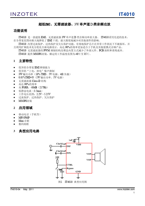
INZOTEK超低EMI、无需滤波器、3W 单声道 D 类音频功放 功能说明IT4010IT4010 是一款超低 EMI、无需滤波器 3W 单声道 D 类音频功率放大器。
IT4010 采用先进的技术, 在全带宽范围内极大地降低了 EMI 干扰,最大限度地减少对其他部件的影响。
IT4010 内置过流保护、过热保护及欠压保护功能,有效地保护芯片在异常工作状况下不被损坏。
并 且利用扩频技术充分优化全新电路设计,高达 90%的效率更加适合于手机及其他便携式音频产品。
IT4010 无需滤波器的 PWM 调制结构及增益内置方式减少了外部元件、PCB 面积和系统成本。
IT4010 提供 MSOP8封装,额定的工作温度范围为-40℃至 85℃。
1 主要特性优异的全带宽 EMI 抑制能力 优异的“上电,掉电”噪声抑制 3W 输出功率(10% THD、5V 电源、4Ω 负载) 0.05%THD+N(1W 输出功率、5V 电源) 无需滤波器 Class-D 结构 高达 90%的效率 高 PSRR:-80dB(217Hz) 低静态电流(3.5mA) 工作电压范围:2.2V~5.25V 过流保护、过热保护、欠压保护 MSOP8封装2 应用领域移动电话(手机等) MP3/PMP Mini 音箱 数码相框3典型应用电路图1IT4010-04 May 2011IT4010 典型应用图 1IT40104INZOTEK参数 表1 芯片最大物理极限值 最小值 最大值 -0.3 -0.3 -65 6.0 VDD+0.3 150 150 260 190 -40 85 +/-8000 150 -150 单位 V V ℃ ℃ ℃ ℃/W ℃ V mA mA极限参数电源电压 VDD INP,INN,CTRL 引脚电压 最大结温 存储温度范围 引脚温度 (焊接 10 秒) 封装热阻JA(MSOP8) 工作温度范围 ESD 防护电压 Latch-up +IT -IT注 1:在极限值之外或任何其他条件下,芯片的工作性能不予保证。
XL4013原厂资料中文版演示

线性调整率与负载调整率:
Efficiency(%) Output voltage(V)
Efficiency VS Load current
100
95
90
85
80
75
70
VIN=8V,VOUT=5V,IOUT=0.1A~4A
65
VIN=12V,VOUT=5V,IOUT=0.1A~4A
VIN=24V,VOUT=5V,IOUT=0.1A~4A
5.070
3.8
5.072
4.0
EFF(%) 53.67 63.43 73.50 77.60 80.40 81.72 82.62 82.96 83.51 83.69 83.84 83.99 84.12 84.05 84.15 83.40 83.54 83.39 83.28 83.29 83.07
转换效率:
版 本:1.1 页 数:第 4 页, 共 6 页
DEMO 实物图
PCB 布局
30mm
40mm
顶层
底层
应用信息
输入电容选择 在连续模式中,转换器的输入电流是一组占空比约为 VOUT/VIN 的方波。为了防止大的瞬态电压,必须采用针对 最大 RMS 电流要求而选择低 ESR(等效串联电阻)输入电容器。对于大多数的应用,1 个 10uF 的输入电容器就足够了, 它 的放置位置尽可能靠近 XL4013 的位置上。最大 RMS 电容器电流由下式给出:
5.057
0.1
5.056
0.2
5.058
0.4
5.058
0.6
5.057
0.8
5.057
1.0
5.057
1.2
5.058
MSP09中文资料
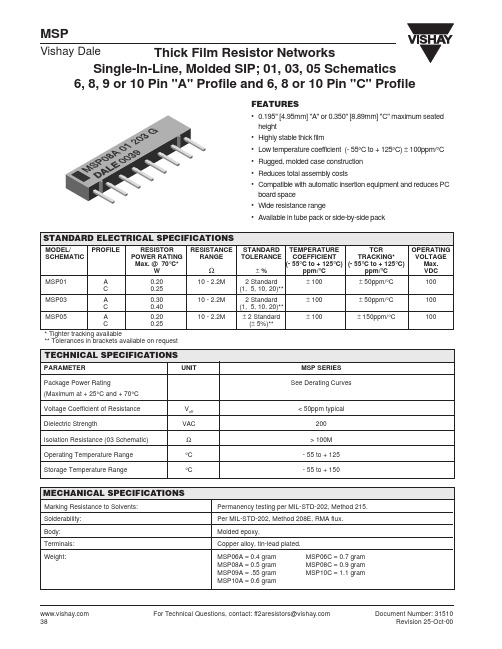
EXAMPLE: MSP08A-01-101G = A molded single-inline thick film resistor network with 8 pins on 0.100" [2.54mm] centers, 0.195" [4.95mm] maximum seated height, 01 Schematic, resistance value of 100 ohm and a tolerance of ± 2%.
DIMENSIONS in inches [millimeters]
A Max. 0.015 [0.381] Min. PIN #1 D Max. 0.090 [2.29] Max.
Vishay Dale
0.100 ± 0.010 [2.54 ± 0.254] Non-Accumulative
0.016 ± 0.003 [0.406 ± 0.076] B C Equals Spaces
Thick Film Resistor Networks, Single-In-Line, Molded SIP
CIRCUIT APPLICATIONS
01 Schematic 5, 7, 8* or 9 resistors with one pin common
The MSPxxx-01 circuit contains 5, 7, 8* or 9 nominally equal resistors, each connected between a common pin (Pin No. 1) and a discrete PC board pin. Commonly used in the following applications: • "Wired OR" Pull-up • MOS/ROM Pull-up/Pull-down • Power Gate Pull-up • Open Collector Pull-up • TTL Input Pull-down • TTL Unused Gate Pull-up
4049芯片
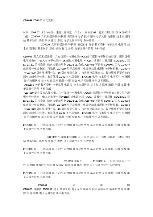
CD4049 CD4050中文资料时间:2009-07-18 21:01:20 来源:资料室作者:编号:6209 更新日期20120824 003537 功能:CD4049 六反相缓冲器/转换器FNX838电子-技术资料-电子元件-电路图-技术应用网站-基本知识-原理-维修-作用-参数-电子元器件符号-各种图纸CD4050 六同相缓冲器/转换器FNX838电子-技术资料-电子元件-电路图-技术应用网站-基本知识-原理-维修-作用-参数-电子元器件符号-各种图纸CD4049是六反相缓冲器,具有仅用一电源电压(VCC)进行逻辑电平转换的特征。
用作逻辑电平转换时,输入高电平电压(V IH)超过电源电压V CD。
该器件主要用作COS/MOS到DTL/TTL的转换器,能直接驱动两个DTL/TTL负载。
CD4049可替换CD4009,因为CD4049仅需要一电源电压,可取代CD4009用于反相器、电源驱动器或逻辑电平转换器。
CD4049与CD4009引出端排列一致,16引出端是空脚,与内部电路无连接。
若使用时不要求高的漏电流或电压转换,推荐使用CD4049六反相器。
FNX838电子-技术资料-电子元件-电路图-技术应用网站-基本知识-原理-维修-作用-参数-电子元器件符号-各种图纸FNX838电子-技术资料-电子元件-电路图-技术应用网站-基本知识-原理-维修-作用-参数-电子元器件符号-各种图纸CD4050是非反相六缓冲器,具有仅用一电源电压(VCC)进行逻辑电平转换的特征。
用作逻辑电平转换时,输入高电平电压(VIH)超过电源电压VCC。
该器件主要用作COS/MOS到DTL/TTL的转换器,能直接驱动两个DTL/TTL负载。
CD4049可替换CD4010,因为CD4050仅需要一电源电压,可取代CD4050用于反相器、电源驱动器或逻辑电平转换器。
CD4050与CD4010引出端排列一致,16引出端是空脚,与内部电路无连接。
常用三极管参数大全

玉林万顺达电脑芯片级维修资料 2010-07-20整理玉林万顺达电脑芯片级维修资料 2010-07-20整理玉林万顺达电脑芯片级维修资料 2010-07-20整理玉林万顺达电脑芯片级维修资料 2010-07-20整理玉林万顺达电脑芯片级维修资料 2010-07-20整理玉林万顺达电脑芯片级维修资料 2010-07-20整理玉林万顺达电脑芯片级维修资料 2010-07-20整理玉林万顺达电脑芯片级维修资料 2010-07-20整理玉林万顺达电脑芯片级维修资料 2010-07-20整理玉林万顺达电脑芯片级维修资料 2010-07-20整理玉林万顺达电脑芯片级维修资料 2010-07-20整理玉林万顺达电脑芯片级维修资料 2010-07-20整理玉林万顺达电脑芯片级维修资料 2010-07-20整理玉林万顺达电脑芯片级维修资料 2010-07-20整理玉林万顺达电脑芯片级维修资料 2010-07-20整理玉林万顺达电脑芯片级维修资料 2010-07-20整理玉林万顺达电脑芯片级维修资料 2010-07-20整理玉林万顺达电脑芯片级维修资料 2010-07-20整理玉林万顺达电脑芯片级维修资料 2010-07-20整理玉林万顺达电脑芯片级维修资料 2010-07-20整理玉林万顺达电脑芯片级维修资料 2010-07-20整理玉林万顺达电脑芯片级维修资料 2010-07-20整理玉林万顺达电脑芯片级维修资料 2010-07-20整理玉林万顺达电脑芯片级维修资料 2010-07-20整理玉林万顺达电脑芯片级维修资料 2010-07-20整理玉林万顺达电脑芯片级维修资料 2010-07-20整理玉林万顺达电脑芯片级维修资料 2010-07-20整理玉林万顺达电脑芯片级维修资料 2010-07-20整理玉林万顺达电脑芯片级维修资料 2010-07-20整理玉林万顺达电脑芯片级维修资料 2010-07-20整理。
西门子STEP7解密

西门子STEP7解密全攻略之MMC程序还原模拟与测试如果您现在还没有卡,或心里没底不敢轻易使用MMC卡,那么就先来模拟一下吧!您需要找来一个普通的随意大小的U盘或普通相机或手机的MMC卡,仿真当作S7的MMC卡来作我们的试验品。
S7-300的解密软件您可能已经下载,那么现在就请打开<MMC写卡软件>,打开<映像文件>文件夹里的<S7-300 2080压机程序>写入到U盘。
到此,您已经拥有了一个仿真的MMC卡了,现在可以按照上面的解密方法破解密码了.....不过此方法仅供学习模拟适用,不能代替S7的MMC卡,也并非绝对不行,如果修改CID和CSD数据的话plc也能认识,但是民用mmc卡和工业mmc卡的技术参数必定不同,比如温度参数,S7的MMC卡上限温度是80度,而普通MMC卡只有60度。
等等原因,所以不建议替代,如果哪位网友替代成功请来信告诉我!怎样打开卡内的程序:用<MMC读卡软件>读出来的文件是一个后缀名为s7img的文件,这是一种映像文件,这种文件是编程软件无论如何也不可能打开的,那么就需要转换了。
具体操作如下图所示:1、运行<S7 MMC卡转换与解密软件>,点击<文件> 下的<打开>,选择你所读出的S7img文件。
2、点击<转换>下的<s7img到wld>,这时会弹出完成消息筐,点击<确定>按钮,到此时转换过程全部完成。
3、运行s7 300 400的编程软件的管理器<SIMATIC Manager>,在<文件>选择项里的<存储卡文件>下点击<打开>,选择你刚才所转换的*.wld文件,程序就打开了!遗憾!但是你看不到硬件组态。
编程软件建议使用STEP7 V5.4中文版或更高,如果您还没有此软件请安装本软件是需要授权的,如果你还没有,请在这里卡文件的还原转换您打开的卡文件如下图1处,只有文件名,并不像2处有cpu型号及硬件组态,完全不如使用MPI电缆下载的好看、好懂。
cd简洁中文
cd40192中文资料
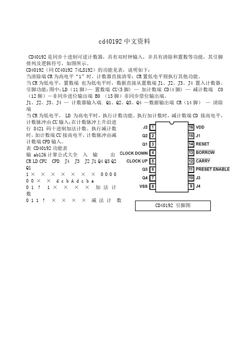
CD40192是同步十进制可逆计数器,具有双时钟输入,并具有清除和置数等功能,其引脚排列及逻辑符号,如图所示。
CD40192(同CC40192 74LS192)的功能见表,说明如下:
当清除端CR为高电平“1”时,计数器直接清零;CR置低电平则执行其他功能。
当CR为低电平,置数端也为低电平时,数据直接从置数端J1、J2、J3、J4 置入计数器。
引脚功能:图中:LD (11脚)—置数端 CU(5脚) —加计数端 CD(4脚) —减计数端 C0 (12脚)-非同步进位输出端 B0 (13脚)非同步借位输出端。
J1、J2、J3、J4 —计数器输入端. Q1、Q2、Q3、Q4 —数据输出端 CR(14脚)—清除端
当CR为低电平, LD 为高电平时,执行计数功能。
执行加计数时,减计数端CD 接高电平,计数脉冲由CU输入;在计数脉冲上升沿进
行8421码十进制加法计数。
执行减计数
时,加计数端CU接高电平,计数脉冲由减
计数端CPD输入。
表 CD40192功能表
输 ab126计算公式大全入输出
CR LD CPU CPD J4 J3 J2 J1 Q4 Q3 Q2
Q1
1 × × × × × × × 0 0 0 0
0 0 × × d c b A d c b a
0 1 ↑ 1 ××××加法计
数
0 1 1 ↑××××减法计数
CD40192 引脚图。
MSP430寄存器配置指导
微控网为你准备的 MSP430F 单片机入门必修课
微控网
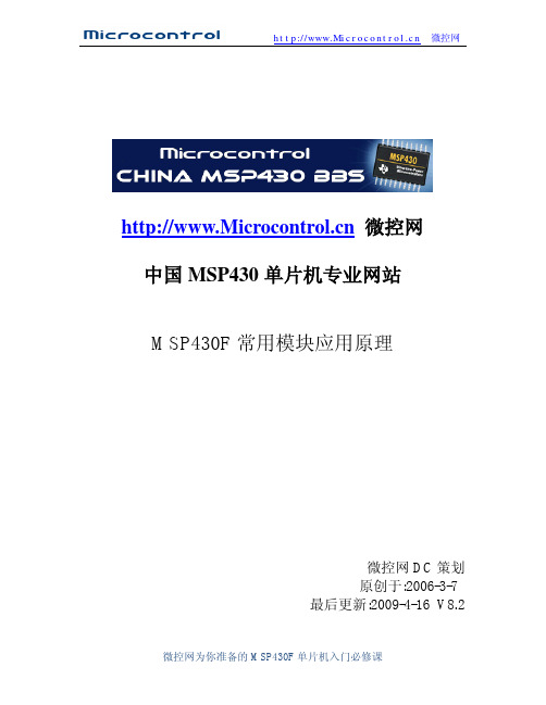
MSP430F1XX 系列时钟模块图 时基模块结构如上图:
MSP430 系列单片机基础时钟主要是由低频晶体振荡器,高频晶体振荡器,数字控制 振荡器(DCO),锁频环(FLL)及 FLL+等模块构成。由于 430 系列单片机中的型号不同, 而时钟模块也将有所不同。虽然不同型号的单片机的时基模块有所不同,但这些模块产 生出来的结果是相同的.在 MSP430F13、14 中是有 TX2 振荡器的,而 MSP430F11X,F11X1 中是用 LFXT1CLK 来代替 XT2CLK 时钟信号的.在时钟模块中有 3 个(对于 F13,F14)时钟 信号源(或 2 个时钟信号源,对于 F11X、F11X1):
BCSCTL1 基本时钟系统控制寄存器 1
7
6
5
4
XT2OFF TXS DIVA.1 DIVA.0
3 XT5V
2
1
0
Rsel.2 Resl.1 Resl.0
XT2OFF 控制 XT2 振荡器的开启与关闭。 TX2OFF=0,XT2 振荡器开启。 TX2OFF=1,TX2 振荡器关闭(默认为 TX2 关闭)
微控网
句:_BIS_SR(LMP3_bits)和_BIC_SR(LPM3 bits) LPM3 和 LPM3_EXIT
它们的定义是一样的。这里说明在 C 语言环境中有些定义的函数是不可见的。但你可以 从 in430.h 文件看到它们的定义。
DCOCTL DCO 控制寄存器
cctlx捕获比较控制寄存器151413121110ccis1scssccicapoutmodxcciexccioutcovccifxtimera有多个捕获比较模块每个模块都有自己的控制寄存器cctlxcaptmod10选择捕获模式00禁止捕获模式01上升沿捕获10下降沿捕获11上升沿与下降沿都捕获ccisi0在捕获模式中用来定提供捕获事件的输入端00选择ccixa01选择ccixb10选择gnd11选择vccscs选择捕获信号与定时器时钟同步异步关系0异步捕获1同步捕获异步捕获模式允许在请求时立即将ccifg置位和捕获定时器值适用于捕获信号的周期远大于定时器时钟周期的情况
CD4013中文资料及应用
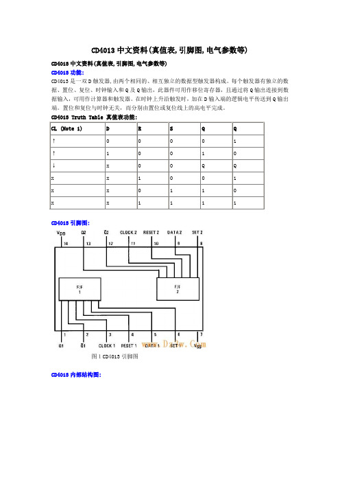
CD4013中文资料(真值表,引脚图,电气参数等)CD4013中文资料(真值表,引脚图,电气参数等)CD4013功能:CD4013是一双D触发器,由两个相同的、相互独立的数据型触发器构成。
每个触发器有独立的数据、置位、复位、时钟输入和Q及Q输出,此器件可用作移位寄存器,且通过将Q输出连接到数据输入,可用作计算器和触发器。
在时钟上升沿触发时,加在D输入端的逻辑电平传送到Q输出端。
置位和复位与时钟无关,而分别由置位或复位线上的高电平完成。
CD4013 Truth Table 真值表功能:CL (Note 1) D R S Q Q↑0 0 0 0 1↑ 1 0 0 1 0↓x 0 0 Q Qx x 1 0 0 1x x 0 1 1 0x x 1 1 1 1CD4013引脚图:图1CD4013引脚图CD4013内部结构图:图2CD4013内部电路图图3 CD4013逻辑图CD4013电气参数:Absolute Maximum Ratings 绝对最大额定值:DC Supply Voltage 直流供电电压 (VDD) -0.5 VDC to +18 VDC Input Voltage输入电压 (VIN) -0.5 VDC to VDD +0.5 VDC Storage Temperature Range储存温度范围 (TS) -65℃ to +150℃Recommended Operating Conditions 建议操作条件:DC Electrical Characteristics 直流电气特性:AC Electrical Characteristics 交流电气特性:图4 切换时间波形CD4013应用电路:图5(左)和图(右)中的CD4013是CMOS双D触发器,这类电路置位和复位信号是高电平有效,由于开关闭合时电容可视为短路而产生高电平,使RD=1,Q=0;若将此信号加到SD,则SD=1,Q=1;置位、复位过后,电容充电而使RD(SD)变为0,电路可进入计数状态。
sunset Q931信令测试仪使用手册
SUNSET MTT基本操作用户手册(SA942)Isdn用户手册:MAN-22060-US006 REV A00晨兴通信公司序言该测试仪软件发布在MMC内存卡中,因此,测试仪需要一块适配器(MMC-PCMCIA适配卡)来更换内部卡槽中PCMCIA软件卡。
注意:当测试仪开机时,不要尝试取出卡与/或适配器,这样会毁坏测试仪。
更换卡:(1)关机,拔掉线缆(2)如果是装配的话,翻下测试仪背面的保护顶盖(3)按下卡左边的黑色退出器拉扣,取出旧卡,如果卡槽内有卡,先要取出保护卡或靠外面卡槽内的SRAM卡(4)按图示步骤操作,插入新卡(MMC卡)和适配器。
A.将MMC软件卡插入MMC-PCMCIA适配卡。
B.将MMC-PCMCIA适配卡插入测试仪背面靠里的卡槽内。
适配卡的使用型号视测试仪的型号(MODEL)而定,可参照下表。
C.确保MMC-PCMCIA适配卡安插牢固。
提示:安插之前,适配器与退出器不在一个水平高度!(5)如果可用的话,将保护卡或SRAM卡插入靠外面的卡槽。
(6)如果是装配的话,翻上保护顶盖。
(7)开机并确认测试仪运行正常。
安装新软件后:(1)测试仪可能需要升级它的LCD驱动程序,如果是的话,过程一般需要5分钟,在此期间测试仪不能关机。
如果发生问题,拨打客户服务电话:001-888-922-9375。
(2)执行NVRAM删除。
该步骤通常在安装新软件后须执行,可参考用户手册关于“NVRAM删除指南”章节。
操作预防事项长期保持卡和适配器干燥不能弯曲或使适配器遭受强烈震动不能直接触碰卡或适配器上的任何带电连接器该适配器只能与SUNRISE TELECOM的产品配套使用,不能将该适配器插入到任何计算机的PCMCIA卡槽,因为这样可能会损坏你的计算机操作差异测试仪的大部分操作与MMC升级前相同,主要的差异是当你从模块主菜单进入CHASSIS主菜单时,模块功能将停用。
当在CHASSIS功能与模块功能间切换时测试仪会提示你确认,以避免不小心退出。
S7-300CPU 存储器介绍及存储卡使用

S7-300CPU 存储器介绍及存储卡使用P LC原理及技术资料, 技术资料Technology LibrariesAdd comments1.用于新型S7-300 CPU的MMC卡MMC 卡是一种FEPROM 卡,用于新型的S7-300 CPU,包括紧凑型CPU和由标准型更新的新型CPU。
新型CPU均没有内置的装载存储器,必须使用MMC 卡作为其装载存储器保存用户数据CPU掉电时,会自动将工作存储器中的数据拷贝到MMC中,保存DB块数据。
MMC 卡需要用户根据程序大小单独订货,选型时建议大于CPU 工作内存,CPU313,CPU314,CPU315-2DP,CPU317-2DP 系列CPU的可插拔MMC卡最大支持8 MB ,其他最高支持4 MB 用于新型S7-300 CPU的MMC 卡(Micro Memory Card )型号如下:64 KB 6E S7 953-8LF11-0AA0128 KB 6E S7 953-8LG11-0AA0512 KB 6E S7 953-8LJ11-0AA02 MB 6E S7953-8LL11-0AA04 MB 6E S7953-8LM11-0AA08 MB 6E S7 953-8LP11-0AA02.MMC卡使用寿命MMC的使用寿命主要取决于以下因素:(1). 删除或编程步骤的数量。
使用MMC的CPU有SFC 82,83,84等特性,可以进行数据的读写:SFC82“CREA_DBL”:在装载内存(Load Memory)中生成数据块SFC83“READ_DBL”:读装载内存(Load Memory)中的数据块SFC84“WRIT_DBL”:写数据块(内容)到装载内存(Load Memory)即MMC卡中。
但是,请注意由于MMC卡重复写入的次数是有限的,所以当调用SFC 84向MMC卡写数时最好只在相应的时间间隔(例如每小时,每天…)调用。
如果MMC卡在保存时发生故障,相的调用块会发出否定应答,其结果存放在程序的返回值(RET_VAL)中。
MT9094资料

7-45®Features•Programmable µ-Law /A -Law codec and filters •Programmable CCITT (G.711)/sign-magnitude coding•Programmable transmit, receive and side-tone gains•DSP-based:i)Speakerphone switching algorithm ii)DTMF and single tone generator iii)Tone Ringer•Differential interface to telephony transducers •Differential audio paths •Single 5 volt power supplyApplications•Fully featured digital telephone sets •Cellular phone sets•Local area communications stationsDescriptionThe MT9094 DPhone-II is a fully featured integrated digital telephone circuit. Voice band signals are converted to digital PCM and vice versa by a switched capacitor Filter/Codec. The Filter/Codec uses an ingenious differential architecture to achieve low noise operation over a wide dynamic range with a single 5V supply. A Digital Signal Processor provides handsfree speaker-phone operation. The DSP is also used to generate tones (DTMF , Ringer and Call Progress) and control audio gains. Internal registers are accessed through a serial microport conforming to INTEL MCS-51™ specifications. The device is fabricated in Mitel's low power ISO 2-CMOS technology.Figure 1 Functional Block DiagramDigital Signal ProcessorFilter/Codec Gain DSTo DSTi F0i C4i VSSD VDD VSSA VSS SPKR VBias VRefS1S12BP WD PWRST ICCSSCLK DATA 1DATA 2SPKR-SPKR+HSPKR-HSPKR+M+M-MIC+MIC-Transducer Interface22.5/-72dB ∆1.5dB Tx & RxENCODER 7dB DECODER-7dBC-Channel RegistersControl RegistersTiming CircuitsLCD DriverNew Call Tone Generator S/P &P/S ConverterSerial Port (MCS-51Compatible)STATUS ISSUE 2May 1995MT9094Digital Telephone (DPhone-II)ISO 2-CMOS ST -BUS ™ FAMIL Y Ordering Information MT9094AP44 Pin PLCC-40°C to +85°CMT90947-46Figure 2 - Pin ConnectionsPin DescriptionPin #Name Description1M+Non-Inverting Microphone (Input).Non-inverting input to microphone amplifier from the handset microphone.2NC No Connect. No internal connection to this pin.3V Bias Bias Voltage (Output). (V DD /2) volts is available at this pin for biasing external amplifiers.Connect 0.1µF capacitor to V SSA .4V Ref Reference voltage for codec (Output). Nominally [(V DD /2)-1.5] volts. Used internally.Connect 0.1µF capacitor to V SSA .5ICInternal Connection.Tie externally to V SS for normal operation.6PWRST Power-up Reset (Input). CMOS compatible input with Schmitt Trigger (active low).7DSTi ST-BUS Serial Stream (Input).2048 kbit/s input stream composed of 32 eight bit channels;the first four of which are used by the MT9094. Input level is TTL compatible.8DSToST-BUS Serial Stream (Output).2048 kbit/s output stream composed of 32 eight bitchannels. The MT9094 sources digital signals during the appropriate channel, time coincident with the channels used for DSTi.9C4i 4096 kHz Clock (Input). CMOS level compatible.10F0i Frame Pulse (Input). CMOS level compatible. This input is the frame synchronization pulse for the 2048 kbit/s ST -BUS stream.11V SSD Digital Ground. Nominally 0 volts.12NC No Connect. No internal connection to this pin.13SCLKSerial Port Synchronous Clock (Input). Data clock for MCS-51 compatible microport. TTL level compatible.1654324443424140789101112131415163938373635343332313023181920212224252627281729P W R S T I C V B i a s V R e f N C M -V S S A M I C +M I C -M +DSTi DSTo C4i F0i VSSD NC SCLK DATA 2DATA 1CS WDSPKR+SPKR-HSPKR+HSPKR-VDD BP S12S11S10S9S8I C N C N C V S S D S 1S 3S 4S 5S 6S 7S 244 PIN PLCCV S S S P K RMT90947-47NOTES:Intel and MCS-51 are registered trademarks of Intel Corporation, Santa Clara, CA, USA.14DATA 2Serial Data Transmit.In an alternate mode of operation, this pin is used for data transmit fromMT9094. In the default mode, serial data transmit and receive are performed on the DATA 1 pin and DATA 2 is tri-stated.15DATA 1Bidirectional Serial Data.Port for microprocessor serial data transfer compatible withMCS-51 standard (default mode). In an alternate mode of operation , this pin becomes the data receive pin only and data transmit is performed on the DATA 2 pin. Input level TTL compatible.16CS Chip Select (Input). This input signal is used to select the device for microport data transfers.Active low. (TTL level compatible.)17WD Watchdog (Output). Watchdog timer output. Active high.18IC Internal Connection.Tie externally to V SS for normal operation.19,20NC No Connection.No internal connection to these pins.21V SSDDigital Ground. Nominally 0 volts.22-33S1-S12Segment Drivers (Output).12 independently controlled, two level, LCD segment drivers. Anin-phase signal, with respect to the BP pin, produces a non-energized LCD segment. An out-of-phase signal, with respect to the BP pin, energizes its respective LCD segment.34BP Backplane Drive (Output). A two-level output voltage for biasing an LCD backplane.35V DDPositive Power Supply (Input). Nominally 5 volts.36HSPKR-Inverting Handset Speaker (Output). Output to the handset speaker (balanced).37HSPKR+Non-Inverting Handset Speaker (Output). Output to the handset speaker (balanced).38SPKR-Inverting Speaker (Output).Output to the speakerphone speaker (balanced).39SPKR+Non-Inverting Speaker (Output). Output to the speakerphone speaker (balanced).40V SS SPKR Power Supply Rail for Analog Output Drivers.Nominally 0 Volts.41MIC-Inverting Handsfree Microphone (Input).Handsfree microphone amplifier inverting inputpin.42MIC+Non-inverting Handsfree Microphone (Input).Handsfree microphone amplifiernon-inverting input pin.43V SSA Analog Ground.Nominally 0 V .44M-Inverting Microphone (Input). Inverting input to microphone amplifier from the handset microphone.Pin Description (continued)Pin #NameDescriptionMT90947-48OverviewThe Functional Block Diagram of Figure 1 depicts the main operations performed within the DPhone -II .Each of these functional blocks will be described in the sections to follow. This overview will describe some of the end-user features which may be implemented as a direct result of the level of integration found within the DPhone -II .The main feature required of a digital telephone is to convert the digital Pulse Code Modulated (PCM)information, being received by the telephone set, into an analog electrical signal. This signal is then applied to an appropriate audio transducer such that the information is finally converted into intelligible acoustic energy. The same is true of the reverse direction where acoustic energy is converted first into an electrical analog and then digitized (into PCM) before being transmitted from the set. Along the way if the signals can be manipulated, either in the analog or the digital domains, other features such as gain control, signal generation and filtering may be added. More complex processing of the digital signal is also possible and is limited only be the processing power available. One example of this processing power may be the inclusion of a complex handsfree switching algorithm. Finally, most electro-acoustic transducers (loudspeakers) require a large amount of power to develop an effective acoustic signal. The inclusion of audio amplifiers to provide this power is required.The DPhone -II features Digital Signal Processing (DSP) of the voice encoded PCM, complete Analog/Digital and Digital/Analog conversion of audio signals (Filter/CODEC) and an analog interface to the external world of electro-acoustic devices (Transducer Interface). These three functional blocks combine to provide a standard full-duplex telephone conversation utilizing a common handset. Selecting transducers for handsfree operation, as well as allowing the DSP to perform its handsfree switching algorithm, is all that is required to convert the full-duplex handset conversation into a half-duplex speakerphone conversation. In each of these modes,full programmability of the receive path and side-tone gains is available to set comfortable listening levels for the user as well as transmit path gain control for setting nominal transmit levels into the network.The ability to generate tones locally provides the designer with a familiar method of feedback to the telephone user as they proceed to set-up, and ultimately, dismantle a telephone conversation. Also,as the network slowly evolves from the dial pulse/DTMF methods to the D-Channel protocols it is essential that the older methods be available forbackward compatibility. As an example; once a call has been established, say from your office to your home, using the D-Channel signalling protocol it may be necessary to use in-band DTMF signalling to manipulate your personal answering machine in order to retrieve messages. Thus the locally generated tones must be of network quality and not just a reasonable facsimile. The DPhone -II DSP can generate the required tone pairs as well as single tones to accommodate any in-band signalling requirement.Each of the programmable parameters within the functional blocks is accessed through a serial microcontroller port compatible with Intel MCS-51specifications.Functional DescriptionIn this section, each functional block within the DPhone -II is described along with all of the associated control/status bits. Each time a control/status bit(s) is described it is followed by the address register where it will be found. The reader is referred to the section titled ‘Register Summary' for a complete listing of all address map registers, the control/status bits associated with each register and a definition of the function of each control/status bit.The Register Summary is useful for future reference of control/status bits without the need to locate them within the text of the functional descriptions.Filter-CODECThe Filter/CODEC block implements conversion of the analog 3.3kHz speech signals to/from the digital domain compatible with 64kb/s PCM B-Channels.Selection of companding curves and digital code assignment are register programmable. These are CCITT G.711 A-law or µ-Law, with true-sign/Alternate Digit Inversion or true-sign/Inverted Magnitude coding, respectively. Optionally, sign-magnitude coding may also be selected for proprietary applications.The Filter/CODEC block also implements transmit and receive audio path gains in the analog domain.These gains are in addition to the digital gain pad provided in the DSP section and provide an overall path gain resolution of 0.5dB. A programmable gain,voice side-tone path is also included to provide proportional transmit speech feedback to the handset receiver so that a dead sounding handset is not encountered. Figure 3 depicts the nominal half-channel and side-tone gains for the DPhone -II .MT90947-49On PWRST (pin 6) the Filter/CODEC defaults such that the side-tone path, dial tone filter and 400Hz transmit filter are off, all programmable gains are set to 0dB and µ-Law companding is selected. Further,the Filter/CODEC is powered down due to the PuFC bit (Transducer Control Register, address 0Eh) being reset. This bit must be set high to enable the Filter/CODEC.The internal architecture is fully differential to provide the best possible noise rejection as well as to allow a wide dynamic range from a single 5 volt supply design. This fully differential architecture is continued into the Transducer Interface section to provide full chip realization of these capabilites.A reference voltage (V Ref ), for the conversion requirements of the CODER section, and a bias voltage (V Bias ), for biasing the internal analog sections, are both generated on-chip. V Bias is also brought to an external pin so that it may be used for biasing any external gain plan setting amplifiers. A 0.1µF capacitor must be connected from V Bias to analog ground at all times. Likewise, although V Ref may only be used internally, a 0.1µF capacitor from the V Ref pin to ground is required at all times. It is suggested that the analog ground reference point for these two capacitors be physically the same point.To facilitate this the V Ref and V Bias pins are situated on adjacent pins.The transmit filter is designed to meet CCITT G.714specifications. The nominal gain for this filter path is 0dB (gain control = 0dB). An anti-aliasing filter isSERIAL PORTDSP GAIN*FILTER/CODECTRANSDUCER INTERFACEPCMPCM–72 to +22.5 dB (1.5dB steps)DTMF,Tone Ringer &Handsfree–72 to +22.5 dB (1.5dB steps)Receive Filter Gain 0 to –7 dB (1 dB steps)Side-tone –9.96 to +9.96dB (3.32 dB steps)Side-tone Nominal Gain Transmit Filter Gain 0 to +7dB (1 dB steps)µ-Law –11 dB Α-Law –18.8 dB-6 dBSpeaker Gain 0 to –24 dB (8 dB steps)Receiver DriverSpeaker Phone Driver 0.2dB*Tone Ringer (input from DSP)Transmit GainM U Xµ-Law –6.3 dB Α-Law –3.7 dB µ-Law 6.1dB Α-Law 15.4dBMIC+MIC–M+M–-6 dB HSPKR+HSPKR–SPKR+SPKR–Speakerphone Speaker (40Ω nominal)(32Ω min)Handsfree mic Transmitter microphoneHandset Receiver (150Ω)Transmit Internal to DeviceExternal to DeviceDIGITAL DOMAINANALOG DOMAIN7575Note: *gain the same for A-Law and m −LawReceiveFigure 3 - Audio Gain PartitioningMT90947-50included. This is a second order lowpass implementation with a corner frequency at 25kHz.Attenuation is better than 32dB at 256 kHz and less than 0.01dB within the passband.An optional 400Hz high-pass function may be included into the transmit path by enabling the Tfhp bit in the Transducer Control Register (address 0Eh).This option allows the reduction of transmitted background noise such as motor and fan noise.The receive filter is designed to meet CCITT G.714specifications. The nominal gain for this filter path is 0 dB (gain control = 0dB). Filter response is peaked to compensate for the sinx/x attenuation caused by the 8kHz sampling rate.The Rx filter function can be altered by enabling the DIAL EN control bit in the Transducer Control Register (address 0Eh). This causes another lowpass function to be added, with a 3dB point at 1000Hz. This function is intended to improve the sound quality of digitally generated dial tone received as PCM.Transmit sidetone is derived from the Tx filter and is subject to the gain control of the Tx filter section.Sidetone is summed into the receive path after the Rx filter gain control section so that Rx gain adjustment will not affect sidetone levels. The side-tone path may be enabled/disabled with the SIDE EN bit located in the Transducer Control Register (address 0Eh). See also STG 0-STG 2(address 0Bh).Transmit and receive filter gains are controlled by the TxFG 0-TxFG 2 and RxFG 0-RxFG 2 control bits respectively. These are located in the FCODEC Gain Control Register 1 (address 0Ah). Transmit filter gain is adjustable from 0dB to +7dB and receive filter gain from 0dB to -7dB, both in 1dB increments.Side-tone filter gain is controlled by the STG 0-STG 2control bits located in the FCODEC Gain Control Register 2 (address 0Bh). Side-tone gain is adjustable from -9.96dB to +9.96dB in 3.32dB increments.Law selection for the Filter/CODEC is provided by the A/µ companding control bit while the coding scheme is controlled by the sign-mag/CCITT bit.Both of these reside in the General Control Register (address 0Fh).Digital Signal ProcessorThe DSP block is located, functionally, between the serial ST -BUS port and the Filter/CODEC block. Itsmain purpose is to provide both a digital gain control and a half-duplex handsfree switching function. The DSP will also generate the digital patterns required to produce standard DTMF signalling tones as well as single tones and a tone ringer output. A programmable (ON/OFF) offset null routine may also be performed on the transmit PCM data stream. The DSP can generate a ringer tone to be applied to the speakerphone speaker during normal handset operation so that the existing call is not interrupted.The main functional control of the DSP is through two hardware registers which are accessible at any time via the microport. These are the Receive Gain Control Register at address 1Dh and the DSP Control Register at address 1Eh. In addition, other functional control is accomplished via multiple RAM-based registers which are accessible only while the DSP is held in a reset state. This is accomplished with the DRESET bit of the DSP Control Register. Ram-based registers are used to store transmit gain levels (20h for transmit PCM and 21h for transmit DTMF levels), the coefficients for tone and ringer generation (addresses 23h and 24h),and tone ringer warble rates (address 26h). All undefined addresses below 20h are reserved for the temporary storage of interim variables calculated during the execution of the DSP algorithms. These undefined addresses should not be written to via the microprocessor port. The DSP can be programmed to execute the following micro-programs which are stored in instruction ROM, (see PS0 to PS2, DSP Control Register, address 1Eh). All program execution begins at the frame pulse boundary.PS2 PS1 PS0Micro-program000Power up reset program1Transmit and receive gain control program; with autonulling of the transmit PCM, if the AUTO bit is set (see address 1Dh)010DTMF generation plus transmit and receive gain control program (autonull available via the AUTO control bit)011Tone ringer plus transmit and receive gain control program (autonull available via the AUTO control bit)100handsfree switching program101110Last three selections reserved111MT90947-51Note: For the DSP to function it must be selected tooperate, in conjunction with the Filter/Codec, in one of the B-Channels. Therefore, one of the B-Channel enable bits must be set (see Timing Control, address 15h : bits CH 2EN and CH 3EN).Power Up reset ProgramA hardware power-up reset (pin 6,PWRST) will initialize the DSP hardware registers to the default values (all zeros) and will reset the DSP program counter. The DSP will then be disabled and the PCM streams will pass transparently through the DSP . The RAM-based registers are not reset by the PWRST pin but may be initialized to their default settings by programming the DSP to execute the power up reset program. None of the micro-programs actually require the execution of the power up reset program but it is useful for pre-setting the variables to a known condition. Note that the reset program requires one full frame (125µSec) for execution.Gain Control ProgramGain control is performed on converted linear code for both the receive and the transmit PCM. Receive gain control is set via the hardware register at address 1Dh (see bits B0 - B5) and may be changed at any time. Gain in 1.5dB increments is available within a range of +22.5dB to -72dB. Normal operation usually requires no more than a +20 to -20dB range of control. However, the handsfree switching algorithm requires a large attenuation depth to maintain stability in worst case environments, hence the large (-72 dB) negative limit. Transmit gain control is divided into two RAM registers, one for setting the network level of transmit speech (address 20h) and the other for setting the transmit level of DTMF tones into the network (address 21h). Both registers provide gain control in 1.5dB increments and are encoded in the same manner as the receive gain control register (see address 1Dh, bits B0 - B5). The power up reset program sets the default values such that the receive gain is set to -72.0 dB, the transmit audio gain is set to 0.0dB and the transmit DTMF gain is set to -3.0dB (equivalent to a DTMF output level of -4dBm0 into the network).Optional Offset NullingTransmit PCM may contain residual offset in the form of a DC component. An offset of up to ±fifteen linear bits is acceptable with no degradation of the parameters defined in CCITT G.714. The DPhone -II filter/CODEC guarantees no more than ±ten linear bits of offset in the transmit PCM when the autonullroutine is not enabled. By enabling autonulling (see AUTO in the Receive Gain Control Register, address 1Dh) offsets are reduced to within ±one bit of zero.Autonulling circuitry was essential in the first generations of Filter/Codecs to remove the large DC offsets found in the linear technology. Newer technology has made nulling circuitry optional as offered in the DPhone -II .DTMF and Gain Control ProgramThe DTMF program generates a dual cosine wave pattern which may be routed into the receive path as comfort tones or into the transmit path as network signalling. In both cases, the digitally generated signal will undergo gain adjustment as programmed into the Receive Gain Control and the Transmit DTMF Gain Control registers. The composite signal output level in both directions is -4dBm0 when the gain controls are set to 2Eh (-3.0 dB). Adjustments to these levels may be made by altering the settings of the gain control registers. Pre-twist of 2.0dB is incorporated into the composite signal. The frequency of the low group tone is programmed by writing an 8-bit coefficient into Tone Coefficient Register 1 (address 23h), while the high group tone frequency uses the 8-bit coefficient programmed into Tone Coefficient Register 2 (address 24h). Both coefficients are determined by the following equation:COEFF = 0.128 x Frequency (in Hz)where COEFF is a rounded off 8 bit binary integer A single frequency tone may be generated instead of a dual tone by programming the coefficient at address 23h to a value of zero. In this case thefrequency of the single output tone is governed by the coefficient stored at address 24h.Table 1DTMF Signal to distortion:The sum of harmonic and noise power in the frequency band from 50Hz to 3500Hz is typically more than 30dB below the power in the tone pair. All individual harmonics are typically more than 40dB below the level of the low group tone.Frequency(Hz)COEFActual Frequency%Deviation69759h 695.3-.20%77063h 773.4+.40%8526Dh 851.6-.05%94179h 945.3+.46%12099Bh 1210.9+.20%1336ABh 1335.9.00%1477BDh 1476.6-.03%1633D1h1632.8-.01%MT90947-52Table 1 gives the standard DTMF frequencies, the coefficient required to generate the closest frequency, the actual frequency generated and the percent deviation of the generated tone from the nominal.Tone Ringer and Gain Control ProgramA locally generated alerting (ringing) signal is used to prompt the user when an incoming call must be answered. The DSP uses the values programmed into Tone Coefficient Registers 1 and 2 (addresses 23h and 24h) to generate two different squarewave frequencies in PCM code. The amplitude of the squarewave frequencies is set to a mid level before being sent to the receive gain control block. From there the PCM passes through the decoder and receive filter, replacing the normal receive PCM data,on its way to the loudspeaker driver. Both coefficients are determined by the following equation:COEFF = 8000/Frequency (Hz)where COEFF is a rounded off 8 bit binary integer The ringer program switches between these two frequencies at a rate defined by the 8-bit coefficient programmed into the Tone Ringer Warble Rate Register (address 26h). The warble rate is defined by the equation:Tone duration (warble frequencyin Hz) = 500/COEFFwhere 0 < COEFF < 256, a warble rate of 5-20Hz is suggested.An alternate method of generating ringer tones to the speakerphone speaker is available. With this method the normal receive speech path through the decoder and receive filter is uninterrupted to the handset,allowing an existing conversation to continue. The normal DSP and Filter/CODEC receive gain control is also retained by the speech path. When the OPT bit (DSP Control Register address 1Eh) is set high the DSP will generate the new call tone according to the coefficients programmed into registers 23h, 24h and 26h as before. In this mode the DSP output is no longer a PCM code but a toggling signal which is routed directly through the New Call Tone gain control section to the loudspeaker driver. Refer to the section titled ‘New Call Tone’.Handsfree ProgramA half-duplex speakerphone program, fully contained on chip, provides high quality gain switching of the transmit and receive speech PCM to maintain loop stability under most network and local acoustic environments. Gain switching is performed in continuous 1.5dB increments and operates in a complimentary fashion. That is, with the transmit path at maximum gain the receive path is fully attenuated and vice versa. This implies that there is a mid position where both transmit and receive paths are attenuated equally during transition. This is known as the idle state.Of the 64 possible attenuator states, the algorithm may rest in only one of three stable states; full receive, full transmit and idle. The maximum gain values for full transmit and full receive are programmable through the microport at addresses 20h and 1Dh respectively, as is done for normal handset operation. This allows the user to set the maximum volumes to which the algorithm will adhere. The algorithm determines which path should maintain control of the loop based upon the relative levels of the transmit and receive audio signals after the detection and removal of background noise energy. If the algorithm determines that neither the transmit or the receive path has valid speech energy then the idle state will be sought. The present state of the algorithm plus the result of the Tx vs. Rx decision will determine which transition the algorithm will take toward its next stable state. The time durations required to move from one stable state to the next are parameters defined in CCITT Recommendation P .34 and are used by default by this algorithm (i.e., build-up time, hang-over time and switching time).Quiet CodeThe DSP can be made to send quiet code to the decoder and receive filter path by setting the RxMUTE bit high. Likewise, the DSP will send quiet code in the transmit (DSTo) path when the TxMUTE bit is high. Both of these control bits reside in the DSP Control Register at address 1Eh. When either of these bits are low, their respective paths function normally.MT90947-53Transducer InterfacesFour standard telephony transducer interfaces are provided by the DPhone -II . These are:±The handset microphone inputs (transmitter),pins M+/M- and the speakerphone microphone inputs, pins MIC+/MIC-. The transmit path is muted/not-muted by the MIC EN control bit.Selection of which input pair is to be routed to the transmit filter amplifier is acomplished by the MIC/HNSTMIC control bit. Both of these reside in the Transducer Control Register (address 0Eh). The nominal transmit path gain may be adjusted to either 6.1dB (suggested for µ-Law)or 15.4dB (suggested for A-Law). Control of this gain is provided by the MICA/u control bit (General Control Register, address 0Fh). This gain adjustment is in addition to the programmable gain provided by the transmit filter and DSP .±The handset speaker outputs (receiver), pins HSPKR+/HSPKR-. This internally compensated, fully differential output driver is capable of driving the load shown in Figure 4.This output is enabled/disabled by the HSSPKR EN bit residing in the Transducer Control Register (address 0Eh). The nominal handset receive path gain may be adjusted to either -12.3dB (suggested for µ-Law) or - 9.7dB (suggested for A-Law). Control of this gain is provided by the RxA/u control bit (General Control Register, address 0Fh). This gain adjustment is in addition to the programmable gain provided by the receive filter and DSP .±The loudspeaker outputs, pins SPKR+/SPKR-.This internally compensated, fully differential output driver is capable of directly driving 6.5vpp into a 40 ohm load. This output is enabled/disabled by the SPKR EN bit residing in the Transducer Control Register (address 0Eh). The nominal gain for this amplifier is 0.2dB.C-ChannelAccess to the internal control and status registers of Mitel basic rate, layer 1, transceivers is through the ST -BUS Control Channel (C-Channel), since direct microport access is not usually provided, except in the case of the SNIC (MT8930). The DPhone -II provides asynchronous microport access to the ST -BUS C-Channel information on both DSTo and DSTi via a double-buffered read/write register (address 14h). Data written to this address is transmitted on the C-Channel every frame when enabled by CH 1EN (see ST -BUS/Timing Control).Figure 4 - Handset Speaker DriverLCDA twelve segment, non-multiplexed, LCD display controller is provided for easy implementation of various set status and call progress indicators. The twelve output pins (S n ) are used in conjunction with 12 segment control bits, located in LCD Segment Enable Registers 1&2 (addresses 12h and 13h), and the BackPlane output pin (BP) to control the on/off state of each segment individually.The BP pin drives a continuous 62.5Hz, 50% duty cycle squarewave output signal. An individual segment is controlled via the phase relationship of its segment driver output pin with respect to the backplane, or common, driver output. Each of the twelve Segment Enable bits corresponds to a segment output pin. The waveform at each segment pin is in-phase with the BP waveform when its control bit is set to logic zero (segment off) and is out-of-phase with the BP waveform when its control bit is set to a logic high (segment on). Refer to the LCD Driver Characteristics for pin loading information.MicroportA serial microport, compatible with Intel MCS-51(mode 0) specifications, provides access to all DPhone -II internal read and write registers. This microport consists of three pins; a half-duplex transmit/receive data pin (DATA1), a chip select pin (CS) and a synchronous data clock pin (SCLK).On power-up reset (PWRST) or with a software reset (RST), the DATA1 pin becomes a bidirectional (transmit/receive) serial port while the DATA2 pin is internally disconnected and tri-stated.HSPKR+HSPKR-75Ω75Ω1000 pF150 ohm load(speaker)1000 pFgroundMT9094。
芯片手册
功能简述 ............................................................................ 46 编程指南 ............................................................................ 46 寄存器 .............................................................................. 47
pl3201芯片技术指标封装和管脚定义电器参数电特性测量项目符号测试条件测量点最小典型最大单位iwmax所有功能12ma工作电流iwmin所有功能禁用ma工作电压vw标准510pl3201单相多功能电子式载波电能表专用soc北京福星晓程电子科技股份有限公司芯片手册参考电压vref218参考电压温度系数30ppm相对agndupuni1pi1ni0pi0n600模拟输入vppsigin800mv时钟输入osc9620mhz有功功率误差1无功功率误差5vih24输入vil08vohioh3ma40输出voliol10ma04直流电源抑制输出频率误差250mv02交流电源抑制输出频率误差200mv100hz纹波03adc失调模拟输入直流失调13mv增益误差无失调极限参数项目符号极值单位储藏温度tstr60tsr150焊接温度焊接10tilt260ts215tif220工作温度topr40电源电压avdddvdd封装参数pl3201单相多功能电子式载波电能表专用soc北京福星晓程电子科技股份有限公司芯片手册pl3201单相多功能电子式载波电能表专用soc北京福星晓程电子科技股份有限公司芯片手册pl3201单相多功能电子式载波电能表专用soc北京福星晓程电子科技股份有限公司芯片手册pl3201单相多功能电子式载波电能表专用soc北京福星晓程电子科技股份有限公司芯片手册pl3201单相多功能电子式载波电能表专用soc北京福星晓程电子科技股份有限公司芯片手册管脚定义100pin80pin64pindescriptioni1p电流通道1模拟信号全差分输入端典型vpp450mv满量程pga4i2p电流通道2模拟信号全差分输入端典型vpp450mv满量程pga4un电压通道模拟信号全差分输入端典型vpp450mv满量程agndpwr芯片模拟部分电源地模拟部分地要与数字部分地分开qcf10无功瞬时功率脉冲输出校表用pcf11有功瞬时功率脉冲输出校表用s3012s3113lcdseg驱动引脚mclr141010全芯片手动复位输入上升沿下降沿均触发正常工作时要置1s01511s11612s21713lcdseg驱动引脚p2318p37191411p36201512p35211613p34221714端口端口复用说明
MMC_uint_A型说明书要点

技术手册敬请注意:在安装和操作此设备之前,请务必阅读相关安全规则和警告以及设备上粘贴的有关标志。
说明:1、用户在使用MMC unit 设备前,请仔细阅读本手册。
2、用户在阅读本手册时有任何疑问,请与公司技术质量中心联系。
3、为了方便用户和公司之间的联系,提供以下联络方式(见下页)。
联系方式:总部地址:科工科技有限公司中国南京市凤台南路38号邮编:210019技术质量中心电话:(+8625)52458807/52458808/52458809-8026,2128 技术支持热线:(+8625)52444372传真:(+8625)52426019E-MAIL:technic@用户可以在下列网址查到本公司的技术资料和相关信息目录一、概述-------------------------------------------------------5二、安装与接线1 安装----------------------------------------------------71.1 开箱-------------------------------------------------71.2 安装 -------------------------------------------------92 接线----------------------------------------------------13 2.1电气接线要求-------------------------------------------132.2接线端子说明-------------------------------------------15三、操作指南1 盘面定义------------------------------------------------ 212 状态指示灯定义------------------------------------------213 键盘定义------------------------------------------------22四、参数定义1 测量参数------------------------------------------------24 1.1测量菜单显示符号的定义--------------------------------- 241.2测量菜单相关注意事项----------------------------------- 262 设置参数------------------------------------------------30 2.1设置菜单显示符号的定义--------------------------------- 302.2设置菜单相关注意事项----------------------------------- 39五、通讯1 通讯连接------------------------------------------------46 1.1网络布局----------------------------------------------- 46 1.2连接到计算机------------------------------------------- 461.3通讯组网----------------------------------------------- 472 通讯规约------------------------------------------------ 48 2.1 Modbus RTU 通讯--------------------------------------- 482.2 Profibus-DP通讯---------------------------------------61一.概述MMC unit电动机管理控制器(单元型)适用于普通三相交流异步电动机,是将电动机的测量、保护和控制功能结合于一体的综合性智能装置。
MMC-1控制步进、直流电机

8
通道1 通道1工作模式寄存器
用于设置电机通道1的工作模式
符号:Ch1Mode 地址:00H 复位后:00H
bit7 bit6 bit5 bit4 bit3 bit2 bit1 bit0
0/1
0/1
0/1
0/1
0/1
0/1
0/1
0
保留位 (步进电机)细分步数选择: 00-全步,01-1/2步,10-1/4步,11-1/8步 (步进电机)步进增量模式选择:0-重新设置,1-增加 (步进电机)步进电机工作模式:0-自由跑,1-增量设定 电机运行方向:0-正向,1-反向 电机类型选择:0-步进电机,1-直流电机 电机运行选择:0-停止,1-运行
6
引脚说明(3/3) 引脚说明(3/3)
引脚号 21 22 23 24 25 26 27 28 29 30 功能名 CH2STA2/ CH2DC1 CH1STB2/ CH1DC2 CH1STA2/ CH1DC1 CH2STB1 CH2STA1 CH1STB1 Vdd Vss CH3SEN CH2SEN 输入/输出 输出 输出 输出 输出 输出 输出 输入 输入 功能 步进电机:电机通道2的A相相线2信号 直流电机:电机通道2的相线1信号 步进电机:电机通道1的B相相线2信号 直流电机:电机通道1的相线2信号 步进电机:电机通道1的A相相线2信号 直流电机:电机通道1的相线1信号 步进电机:电机通道2的B相相线1信号 直流电机:不使用,悬空 步进电机:电机通道2的A相相线1信号 直流电机:不使用,悬空 步进电机:电机通道1的B相相线1信号 直流电机:不使用,悬空 参考电源 参考地 电机通道3过流检测,输入电压超过1/8Vdd,通道3输出停止, 若不使用可通过电阻(10K)接地 电机通道2过流检测,输入电压超过1/8Vdd,通道2输出停止, 若不使用可通过电阻(10K)接地
东芯IV SEP3203F50系统中MMC卡用户手册
南京博芯电子技术有限公司()SEP3203 系统中 MMC 卡用户手册东芯 IV SEP3203F50 系统中 MMC 卡用户手册南京博芯电子技术有限公司(PROCHIP)-1-南京博芯电子技术有限公司()SEP3203 系统中 MMC 卡用户手册版本说明版本号 V1.0 日期 12/1/2004 编写人 创建文档 描述-2-南京博芯电子技术有限公司()SEP3203 系统中 MMC 卡用户手册目录 目录 ..................................................................................................................................................3 1 .硬件介绍...............................................................................................................................4 1.1 结构框图.......................................................................................................................4 1.2 特性列表.......................................................................................................................4 1.3 寄存器介绍...................................................................................................................4 2 .软件编程...............................................................................................................................5 2.1 寄存器地址定义...........................................................................................................5 2.2 配置时钟寄存器...........................................................................................................6 2.3 命令控制.......................................................................................................................6 2.3.1 CMD0 命令.......................................................................................................7 2.3.2 CMD1 命令.......................................................................................................8 2.3.3 CMD2 命令.....................................................................................................10 2.3.4 CMD3 命令.....................................................................................................12 2.4 数据读写.....................................................................................................................13 3 .命令响应格式.....................................................................................................................25 3.1 R1................................................................................................................................25 3.2 R1b..............................................................................................................................26 3.3 R2................................................................................................................................26 3.4 CMD1 的响应 R3 .......................................................................................................26 4 .ASIX OS 中 MMC 卡的驱动设计....................................................................................27 4.1 mmc_open()...........................................................................................................27 4.2 mmc_close()................................................................................................................27 4.3 mmc_io .......................................................................................................................27 mmc_io(U16 driveno, U32 block, void *buffer, U32 count,int reading)................................27 5 .读卡内寄存器.....................................................................................................................31 5.1 Operating condition register(OCR)........................................................................31 5.2 Card identification register(CID)...........................................................................31 5.3 Card specific data (CSD) ......................................................................................31 6 .中断管理.............................................................................................................................34-3-南京博芯电子技术有限公司()SEP3203 系统中 MMC 卡用户手册1 .硬件介绍1.1 结构框图图 1.1 MMC 卡控制器结构图1.2 特性列表支持对卡的单块(single block) ,多块(multi block)读写,擦除;1.3 寄存器介绍寄存器名称 STR_STP_CLK STATUS CLK_RATE CMD_DAT_CONT RES_TO READ_TO BLK_LEN NOB DAT_COUNT INT_MASK CMD ARG RESPONSE 宽度 32 32 32 32 32 32 32 32 32 32 32 32 128-4-描述 时钟控制寄存器 状态寄存器 时钟速率寄存器 命令/数据控制寄存器 响应时间过长寄存器 读时间过长寄存器 块长度寄存器 BLOCK 数寄存器 要传输的 byte 数 中断屏蔽寄存器 命令数寄存器 命令参数高位寄存器 命令响应寄存器复位值 0x00000000 0x00000000 0x00000036 0x00000000 0x00000040 0x0000ffff 0x00000000 0x00000000 0x00000000 0x00000000 0x00000000 0x00000000 0x00000000南京博芯电子技术有限公司()SEP3203 系统中 MMC 卡用户手册BUFFER_ACCESS32数据寄存器0x00000000STR_STP_CLK 是改变 MMC 卡工作时钟的时候必须用到的寄存器, 所有开关时钟的操作必 须通过它来完成。
