VTP210S中文资料
步进电机驱动控制系统

* 外型尺寸 单位(m m ) A.....32(H)X50(W)X80(D)
*3 采用 PLC 控制 RC-207A/231(HA)时,可预先将程序通过微机输入 EEPROM 内, 而不需要后备电池保持。
B.....27.5(H)X105(W)X56(D) C.....63(H)X105(W)X56(D)
2 1M 8 8 B ◎ ◎ ◎ ◎ ●
可高可可可通贮速先过检由存的将两测软11振程台步件0100000荡序相进设000频输连电定个率入,机加位可后的减可置达,失速以点到步再时进数。脱间行2据M离。P2约约,P轴计S88由。00同算00外步机部运独通行立过。运简作单(的内命贮令E进EP行RO11111111111控M22222222222)33333333311331111111111111111111111111111111111制。4444444442222222222222222222222222222222222244255555555533333333333333333333333333333333333553。666666666444444444444444444444444444444444446647711155555555555555555555555555555555555117777777775222223333344444
南京展示厅:中山北路105号山西电子市场二楼45号(军人俱乐部内) 025-83304112 无锡展示厅:北大街 25 号招商城电子市场 1 区 107 柜 0510- 上海科技京城电子市场(北京东路 668 号)地下一层 A39 室 021-53085086 上海晶滩电子市场 1S12 号(北京东路 731 号) 021-63611806 上海外滩电子名品城 232 室(西藏南路 750 号) 021-63262102
700S-P220X中文资料

9-29Contactors & Control RelaysSafety Control Relays700S-PFeatures•Mechanically linked contacts meeting IEC 947-5-1-L •2…12 poles – all mechanically linked•Red faceplate for easy identification of safety circuits•IEC mechanically linked contacts symbol displayed on front •Double-break contacts to reduce probability of welded contacts •Visual indication of contact state•Tamper resistant cover helps prevent changes which could jeopardize safety•Complete Catalogue number displayed on front •Ideal for use in safety circuitsSpecifications➊ Coil voltage required for proper operation (percent of rated coil voltage).➋ 90% of devices are expected to meet or exceed 12.5 million operations,and 50% of devices are are expected to meet 20 million operations.➌ Temperature inside the panel.T ype700S-PContact Rating Continuous 10 A @ 600V AC / 5 A @ 600V DCRatings Make/BreakAC NEMA A600DCNEMA P600Min. Contact Switching Ratings10V , 50 mA DC SwitchingContacts in SeriesVolts DC24 6412525050060015A 2.2A 1.1A 0.55A 0.24A 0.2A210A 10A 5A 2A 0.7A 0.5A 3 ——7A 3A 1.5A 1.0A 4——10A5A2.5A 1.5AContact Electrical Life—Resistive Loads1.5 mil. ops. at 10A break at 120V AC 14 mil. ops. at 1A break at 120V AC 6 mil. ops. at 1A break at 24V DCCoil Voltage Range ➊AC85…110%DC 80…110%Battery Charging85…115%Coil Con-sump-tion50 Hz60 Hz AC Inrush 132 VA 138 VA Sealed 19.3 VA19 VADCInrush 12.7 W Sealed12.7 WMechanically Linked Contacts All contacts are mechanically linked per IEC 947-5-1 annex L for 2 to 12 polesOperating TimePick-up AC – 10…20 ms / DC – 30…50 ms DropoutAC – 10…20 ms / DC – 20…33 msMechanical Life 12.5 million operations ➋Contact Arrangement 2 to 12 Poles, Double Break Contacts N.O. or N.C. (8 N.C. Maximum)Contact Material/Design Silver Nickel/BifurcatedMountingPanel mount or mount on 700-MP Rail Horizontal Mounting RecommendedT emperatureOperating ➌–20…+65°C (–4…149°F)Storage–40…+65°C (–40…149°F)Wire size per UL/CSA 1X #18 AWG…2X #12 AWG Tightening T orque8…12 lb-in. (0.9…1.4 N•m)Contactors & Control RelaysSafety Control Relays700S-PProduct SelectionT ype S-P Control Relays — AC and DC Coil VoltageFor other coil voltage, consult your local Allen-Bradley sales office. All Catalogue Numbers are factory-stocked.⊗ AC Voltage Suffix CodeThe Catalogue Number as listed is incomplete. Select a voltage suffix code from the table below to complete the Catalogue Number. Example: Catalogue Number 700S-P310 becomes Catalogue Number 700S-P310A1 for a 120V AC coil.Hz24115-120230-240277460-48060A24A1A2A27A49-30Contactors & Control Relays9-31Safety Control Relays700S-P Approximate Dimensions—mm (inches)Dimensions are not intended for manufacturing purposes.(0.5)2- and 4-Pole Bulletin 700S-P RelayApproximate Shipping Weight AC - 0.68kg (1.5lbs),DC - 1.34kg (2.95lbs)6- and 8-Pole Bulletin 700S-P RelayApproximate Shipping Weight AC - 0.79kg (1.75lbs),DC - 1.45kg (3.20lbs)10- and 12-Pole Bulletin 700S-P RelayApproximate Shipping Weight AC - 1.02kg (2.25lbs),DC - 1.68kg (3.7lbs)Universal Mounting Rail for Bulletin 700-P, -PH, -PK,and 700S-P Relays。
S5PV210核心板

DMA-S5PV210-P-336 V02.20
4
核心板正面图
核心板背面图
DMA-S5PV210-P-336 V02.20
5
3 、功能接口说明
3.1 处理器
3.1.1 Samsung S5PV210 处理器
DMA-S5PV210-SOM 采用 Samsung 的高性能处理器 S5PV210,在该芯片上整合了许多外围 接口功能,主要包括: ■ ARM CORTEX-A8 core @1G Hz ■ 3D/2D 高性能加速器 ■ 多媒体编译码核心(MFC) ■ 内置LCD Controller
DMA-S5PV210-P-336 V02.20
3
1 、产品概述
S5PV210-SOM 是内含嵌入式系统的模块(System on Modul,SOM),该模块小巧且包含了 针对产品设计的硬件及软件解决方案,因此在您开发嵌入式产品期间可以大幅降低风险及 减少控制成本,这样可以加速产品上市。
S5PV210-SOM 是基于 ARM CORTEX-A8 核心的 Samsung S5PV210 处理器而设计的,该 模块主要提供了针对无线通讯、个人导航、摄像、移动游戏、移动音乐和视频的播放、移 动电视、PDA 功能、医疗器械等功能产品的应用。藉由功能完整的电路扩充,很方便的设 计底板与模块结合,让您以最低的成本及最快速的时间设计各种不同功能的产品;只需更 换核心模块的功能应用底板及更改核心模块软件功能,省去了最主要的更换 CPU 核心主板 部分,就能轻易简单的更换系统及软、硬件接口功能。
藉由系统核心模块扩充的 DMA-PAD210 Development Kit 开发平台及平台开发软件 BSP 包 的运用,工程师们可以先在此硬件平台上设计相关的应用软件并得到验证,最后该应用软 件可以直接使用在最终的产品上,以加速产品的上市。
ARM编程01_Soc简介及指令集
bic r0, r0, #0x1f // bit clear mrs r0, cpsr // cpsr read specified msr cpsr,r0 // cpsr write specified mov r4, r0 // register transfer mrc p15, 0, r0, c1, c0, 0 // cp15 read mcr p15, 0, r0, c1, c0, 0 // cp15 write tst r2, #0x3 // like and but no dest reg cmp r5, r6 // like sub but no dest reg
24
存储器存取指令
ldr r0, [r2] str r0, [r2] ldr r1, [r2, #4] str r1, [r2, #4] ldr r1, [r2] !, #4 str r1, [r2] !, #4 ldrb r0, [r2] ldrh r0, [r2] ldmia sp, {r0 - lr} stmia r5, {r0 - r3} ldmfd sp, {r0 - lr} adr r0, _start // pc relative addr load
21
大端与小端
ARM支持可配置的大/小端存储形式
31 24 23 16 15 8 7 0
r0 = 0x12345678
12 34 56 78
r1 = 0x100
STR r0, [r1]
3
31
2
1
8 7
0
0
Byte Lane Memory
3
31
2
1
0
DT Swiss SSD210 L后尘抵抗闪电保护手册说明书
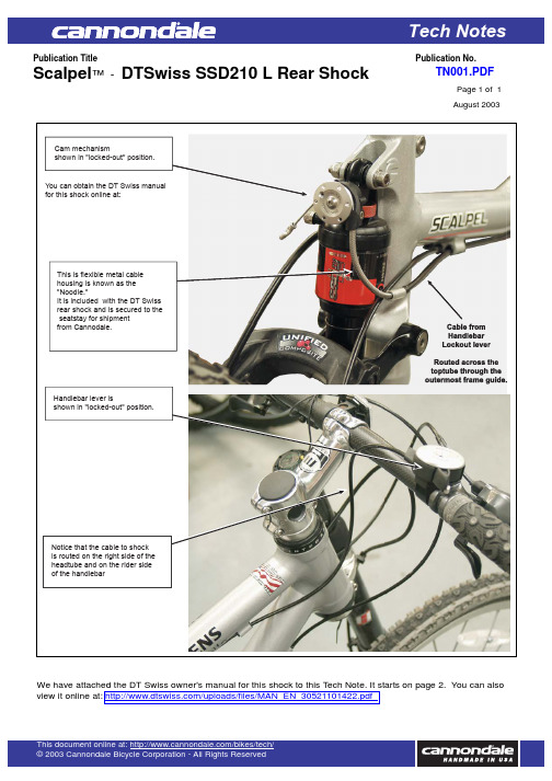
Service Diagram Tech NotesScalpel ™-DTSwiss SSD210L Rear ShockPage 1of 1TN001.PDFAugust 2003Publication TitlePublication No.We haveon page 2.You can also view it onlineSCHWEIZSWITZERLANDSUISSEDT Swiss AG Solothurnstrasse 1Postfach 6023CH-2500 Biel/Bienne 6 Phone:+41 32 344 79 30 Fax:+41 32 341 91 52e-mail:**************** DEUTSCHLANDGERMANYALLEMAGNEDT SwissCustomer Support Deutschland Hegnerweg 17D-71101 SchönaichPhone:+49 7031 410 18 56 Fax:+49 7031 410 18 57 e-mail:********************** FRANKREICHFRANCEFRANCEDT SwissCentre SAV FranceLes grandes ferragesBP 11F-84120 Beaumont de Pertuis Phone:+33 680 249 278 Fax:+33 490 080 019e-mail:**********************ITALIENITALYITALIEBike Suspension CenterVia Monte Leone 4I-39010 CermesPhone:+39 0473 563 107Fax:+39 0473 559 630e-mail:************ÖSTERREICHAUSTRIAAUTRICHEB & S Bike + SportUntersee 153A-4823 SteegPhone:+43 6135 6409Fax:+43 6135 640914e-mail:*****************GROSSBRITANNIENGREAT BRITAINGRANDE-BRETAGNEMadisonBurnell House8 Stanmore HillStanmoreGB-Middlesex HA7 3BQPhone:***********Fax:+44 20 8385 3443e-mail:**************************NIEDERLANDE / BELGIEN / LUXEMBURGNETHERLAND / BELGIUM / LUXEMBURGPAYS-BAS / BELGIQUE / LUXEMBOURGICC ServiceWeststraat 42NL-4527 BT AardenburgPhone:+31 117 49 28 20Fax:+31 117 49 28 35e-mail:****************SPANIENSPAINESPAGNEServicio tecnico DT SwissC / Pozas 36 - 38E-28200 S.L. EscorialPhone:+34 91 890 58 97Fax:+34 91 890 02 69e-mail:***********************VEREINIGTE STAATEN VON AMERIKAUNITED STATES OF AMERICAÉTATS-UNIS D'AMÉRIQUEDT Swiss Inc.2493 Industrial Blvd.USA-Grand Junction / CO 81505Phone:+1 970 242 9232Fax:+1 970 244 8918e-mail:*******************B E D I E N U N G S A N L E I T U N G U N DG A R A N T I E B E S T I M M U N G E N(E U R O P A)U S E R’S M A N U A L A N D W A R R A N T Y(E U R O P E/U S A)M O D E D’E M P L O I E TD I S P O S I T I O N S DE G A R A N T I E(E U R O P E)If your DT Swiss LRCS isstill not working properly, contact yourlocal dealer or our national DT SwissService Centre.Prior removing thelockout shaft, the lockout lever mustbe switched to the lockout position,to prevent internal damage of therear shock!U S E R'S M A N U A L A N D W A R R A N T Y(E U R O P E/U S A)Thank you for choosing DT Swiss LRCS (L ockout R emote C ontrol S ystem)! You have bought a product of best Swiss quality and innovative technology.Please read the complete user's manual attentively before installing or using the DT Swiss LRCS! The manual has to be given to every rider using the unit.The DT Swiss LRCS is a remote control for the DT Swiss SSD 210L rear shock, and is only to be used as such. Do not use the DT Swiss LRCS or any of its components as a tool or toy or for anything else than described in the user's manual.Compliance with the following instructions concerning assembly and maintenance of the DT Swiss LRCS is imperative for proper and accident-free operation. Disregarding these instructions can cause accidents with serious injuries. Functional limitations of the DT Swiss LRCS,which occur because the instructions in this document were not followed correctly, can neither be viewed nor claimed as a manufacturing fault. In addition the manufacturer's guarantee is void under such circumstances.A S S E MB L YIf the DT Swiss LRCS is not assembled correctly or is improperly maintained it is dangerous and may cause accidents with serious injuries.We strongly recommend having the DT Swiss LRCS assembled and maintained by an experienced expert.Compliance with the following instructions concerning assembly of the DT Swiss LRCS is imperative for proper and accident-free operation. Disregarding these instructions can cause accidents with serious injuries.Functional limitations of the DT Swiss LRCS, which occur because the instructions in this document were not followed correctly, can neither be viewed nor claimed as a manufacturing fault. In addition the manufacturer's guarantee is void under such circumstances.If you encounter uncertainties or difficulties, please contact a national DT Swiss Service Centre,for assembly and maintainance of the DT Swiss LRCS by an experienced expert.IMPORTANT!IMPORTANT!IMPORTANT!IMPORTANT!CAUTION!1234678101213The DT Swiss LRCS is designed for the use with the DT Swiss SSD 210L rear shock. The lockout lever has been optimised for the use with Shimano Rapidfire® and Dual Control®-shifters. Using the lockout lever in combination with SRAM Grip Shift®-shifters could cause problems. Using the lockout lever in combination with SRAM Grip Shift®- shifters could cause problems.C O M P A T I B I L I T I E SThe DT Swiss LRCS requires up to ¾" of handlebar width without bends. Please check your handlebars for the required clearance on the left side of the right shifter before assembling.IMPORTANT!On some handlebars you can simplify the assembly of the lockout lever by gently loosening the Shimano Rapidfire® Optical Gear Display. Remember to re-tighten it again after finishing the lockout lever installation!Prior to the assembly remove the rear shock from the bike according to the SSD 210L user's manual. During the whole assembly of the DT Swiss LRCS the rear shock does not get disassembled.A) Check completeness of the required parts.B) If you own a DT Swiss SSD 210L rear shock with the new lockout shaft, skip to step 8.Remove the old lockout pin.CAUTION!Release the locking screw by using a2 mm Allen key.Remove shaft and lever.Add a tiny amount of Loctite® screwlock to the screw. Screw in the screw allthe way.911Release the screw ¼ of a turn.Clip on the DT Swiss LRCS socket(the internal "nose" must snap in).Screw in the M3x20 screw with a2.5 mm Allen key.Mind the low tighteningtorque : Max. 0.6 Nm (5 InLbs)!CAUTION!Place the cable stop in the way thatworks best for your bike.Tight the M2.5x8 screw by using a1.5 mm Allen key.Mind the low tighteningtorque : Max. 0.4 Nm (3 InLbs)!Place the spring’s open end into the leftbore.1415Put on the DT Swiss LRCS disc orientedaccording to the sketch and press it oncompletely. Next lift it to create a gap ofapprox. 8.5 mm, so that the disc’s lowerend may slide over the upper end of thedisc stop nose.Put in the 6 mm Allen key and turnright 270°, press down the disc and letit snap back against the disc stop nose.Tighten the M4x6 screw by using a3 mm Allen key.Mind the thigtening tor-que: Max. 1.3 Nm (11 InLbs)!CAUTION!16Reassemble the shock according to theDT Swiss SSD 210L owner's manual.Make sure the DT SwissLRCS won’t contact any part of the frameor the seatpost whilst using the bike.CAUTION!17181920Place the bracket behind the handle barand under the gear display.Slip on the lever so it is aligned with thebracket.A)Tighten the internal headless M5x10screw by using a 2.5 mm Allen key.Make sure that theDT Swiss LRCS lever, shifter and thebrake lever do not interfere with eachother or hinder you in any way duringoperation!B)The function of the brakes or shiftersshould not be disturbed!CAUTION!Position and shorten the outer cable(not included in set) according to therequirements of your bike. Make sure tohave minimum friction in your cablerouting (use a gore tex-cable ®).Check the clearance ofthe outer cables by flipping the handlebar completely to each side!CAUTION!21Insert the derailleur cable as shown below.Screw on the front cap.22M4x6M3x20M2.5x8A)B)original sizeOLD NEW3.4.5Grease the new lockout shaft and pressit in as shown below.Mind the alignement!correctwrong6.7.OPTIONAL:lead pipe(art.-no.d.3.00.8187)A)A S S E M B L Y D T S W I S S L R C S W I T H T H E R E A R S H O C KB)A S S E M B L Y O F T H E D T S W I S S L R C S L E V E Rcorrectforkrear shockforkrear shock forkrear shockSlip the cable through the hole in theDT Swiss LRCS disc, and then pull thecable to avoid play. The DT Swiss LRCSlever must be positioned in the "open"position!23Tighten the headless screw by using a1.5 mm Allen key.24CAUTION!Check functions:A) Push up the main lever until the release lever snaps in. Close the lockout.B) Press the release lever until the main lever flips down. Open the lockout.2523.24.A)B)C)F U N C T I O N A L T E S T D T S W I S S L R C S26Release the headless screw for two turnsand create a gap of 1 - 3 mm betweendisc stop nose an disc by using a 6 mmAllen key. Pull the cable and tighten theheadless screw again as mentioned instep 24 without releasing the 6 mmAllen key. Repeat step 23 to 25.Does the DT Swiss LRCS works? . . . . . . . . . . .Yes:Skip to step 27.. . . . . . . . . . . . . . . . . . . . . . . . . . . . . . . . . . . . .No:Skip to step 26.27Cut the cable and...28...add the cable end.29Place the black plastic pin in the centreof the front disc.M A I N T E N A N C EA)Release the plastic pin.B)Unscrew the front disc with a 5 mm Allen key.C)Grease the indicated inner portions of the lever as well as shown on the right.D)Close the DT Swiss LRCS lever as mentioned in step 22.E)Check functions as mentioned in step 25.W A R R A N T Y(E U R O P E)The purchaser has the right to claims under the guarantee as covered by general law, against the sales contract partner (retailer). In addition to the general guaranteerequired by law, DT Swiss LTD with head office in Biel/Switzerland, guarantees the DT Swiss LRCS for two years (24 months) from the date of purchase.There shall be no claim under the guarantee for:-normal wear of parts, subject to wear (glidings, seals, sliding surfaces, shifters etc.)- incorrect assembly or in combination with products that do not fit- incorrect maintenance, incorrect repair or alteration- incorrect use, bad treatment, misuse, negligence, carelessness during installation, maintenance or use,commercial use or use in cycling competitions- delivery and transport damageCAUTION!DT Swiss LTD shall reject any liability for both indirect damage caused by accidents and consequential damage. In case of warranty repair/replacement please contact thedealer where you bought the product. DT Swiss LRCS which have to be checked, can be sent postage paid to a DT Swiss Service Centre.Legal venue and place of performance is Biel (Switzerland). Swiss law shall apply. Subject to technical changes. Please keep the user manual and warranty for future use.Have a lot of fun with your DT Swiss LRCS!For DT Swiss Service Centre Addresses see the backor check .Grease these parts.CAUTION!A)B)180°0°60°15.14.A)B)ø 4.0 - 4.2 mmTightening torque:max 2.5 Nm (22 InLbs)!CAUTION!Tightening torque :Max. 1.3 Nm!CAUTION!There shall be no claim under the guarantee for secondary damages in combination with front forks:- incorrect assembly or in combination with products that do not fit- incorrect use, bad treatment, misuse, negligence, carelessness during installation, maintenance or use,commercial use or use in cycling competitionsCAUTION!min. 8.5 mmCheck the lockout shaftfor easy operation by using a 6 mm or¼"- wrench!CAUTION!L I M I T E D E Q U I P M E N T W A R R A N T Y(U S A)DT Swiss LTD makes every effort to assure that its product meets high quality and durability standards and warrants to the original retail consumer/purchaser of our pro-duct that each product is free from defects in materials and workmanship as follows:2 YEAR LIMITED WARRANTY ON THIS LRCS PRODUCT. This warranty does not apply to defects due directly or indirectly tomisuse, abuse, negligence or accidents, repairs or alterations outside our facilities or to a lack of maintenance. DT SWISS LTD LIMITS ALL IMPLIEDWARRANTIES TO THE PERIOD OF TWO YEARS FROM THE DATE OF INITIAL PURCHASE AT RETAIL. EXCEPT AS STATED HEREIN, ANY IMPLIEDWARRANTIES OF MERCHANTABILITY AND FITNESS ARE EXCLUDED. SOME STATES MAY NOT ALLOW LIMITATIONS ON HOW LONG THE IMPLIEDWARRANTY LASTS, SO THE ABOVE LIMITATION MAY NOT APPLY TO YOU. DT SWISS LTD SHALL IN NO EVENT BE LIABLE FOR DEATH, INJURIESTO PERSONS OR PROPERTY OR FOR INCIDENTAL, CONTINGENT, SPECIAL OR CONSEQUENTIAL DAMAGES ARISING FROM THE USE OF OURPRODUCTS. SOME STATES MAY NOT ALLOW THE EXCLUSION OR LIMITATION OF INCIDENTAL OR CONSEQUENTIAL DAMAGES, SO THE ABOVELIMITATION OR EXCLUSION MAY NOT APPLY TO YOU.CAUTION!To take advantage of this warranty, the product or part must be returned for examination, postage prepaid, to the dealer where you bought the product or to aDT Swiss Service Centre.Proof of purchase date and an explanation of the complaint must accompany the product. If our inspection discloses a defect, DT Swiss willeither repair or replace the product or refund the purchase price, if we cannot readily and quickly provide a repair or replacement. DT Swiss will return repaired product orreplacement at DT Swiss expense, but if it is determined there is no defect, or that the defect resulted from causes not within the scope of this warranty, then the usermust bear the cost of shipping. This warranty gives you specific legal rights, and you may also have other rights which vary from state to state.Legal venue and place of performance is Biel (Switzerland). Swiss law shall apply. Subject to technical changes.Please keep the user manual and warranty for future use.Have a lot of fun with your DT Swiss LRCS!Indication:Weight difference of conversion: 59 g (exkl. cable)Tightening torque:Max. 2.5 Nm (22 InLbs)!CAUTION!。
基于s5pv210外部中断使用指南
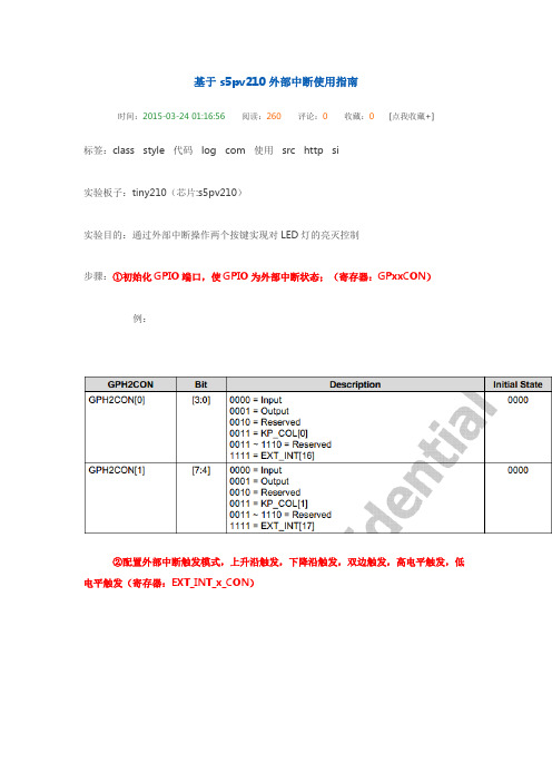
基于s5pv210外部中断使用指南时间:2015-03-24 01:16:56阅读:260评论:0收藏:0 [点我收藏+]标签:class style代码log com使用src http si实验板子:tiny210(芯片:s5pv210)实验目的:通过外部中断操作两个按键实现对LED灯的亮灭控制步骤:①初始化GPIO端口,使GPIO为外部中断状态;(寄存器:GPxxCON)例:②配置外部中断触发模式,上升沿触发,下降沿触发,双边触发,高电平触发,低电平触发(寄存器:EXT_INT_x_CON)例:③取消屏蔽外部中断(寄存器:EXT_INT_x_MASK)例:④通过向量中断控制器(VIC)使能中断(寄存器:VIC0INTENABLE,VIC1INTENABLE,VIC2INTENABLE,VIC3INTENABLE)(注:几乎每一个中断都有其对应的VIC)注:VICINTENABLE寄存器分别包括VIC0,IVC1,VIC2,VIC3四个,每一个中断控制器有32位,每一位对应一个中断源(假如你要使能外部中断1,那么首先要先找到外部中断1对应哪一个中断控制器,然后找到这个中断控制器的相应位为设置)⑤设置中断程序入口(寄存器:VICxVECTADDRx)例:*(VICxVECTADDRx) = 函数名(函数名就是一个地址)⑥开总中断1__asm__(2/*开中断*/3"mrs r0,cpsr\n"4"bic r0, r0, #0x80\n"5"msr cpsr_c, r0\n"6:7:8);⑦编写中断处理程序(清除中断寄存器:EXT_INT_x_PEND)1void函数名()2{3//1. 保存环境45//2. 中断处理67//3. 清除中断8*(EXT_INT_x_PEND) = ~0x0;//写1清除中断标志9*(VICxADDRESS) = 0;10//4. 恢复环境11}中断编写思维导图(仅供参考流程思路):总结:由中断编写思维导图应该有的思路是:1. 对相应GPIO以及中断源的初始化2. 当中断发生,中断源对应的PEND寄存器会被置1,所以在中断处理程序里应该清除中断标志(注:写1清除中断)3. 当中断发生,如果MASK寄存器没有取消屏蔽,则中断不被允许,所以在编写中断程序时应首先取消相应中断的屏蔽4. 别忘了VIC的初始化,包括用VICINTENABLE对相应中断进行使能,用VICVECTADDR寄存器设置中断处理程序入口s3c2440示例代码(仅供参考思路步骤,与s5pv210不对应):1void key_init()2{3rGPGCON &= ~(0x3 << 0); //设置GPGO—EINT[8]4rGPGCON |= (0x2 << 0); //设置GPGO—EINT[8]5rEXTINT1 &= ~(0xf << 0); //触发方式为低电平有效6rEINTPEND |= (1 << 8); //清中断7rEINTMASK &= ~(1 << 8); //允许外部中断8pISR_EINT8_23 = (U32)Key_handler; //中断服务程序9EnableIrq(BIT_EINT8_23); //允许中断(INTMSK)10}1112static void __irq key_handler()13{14if (rINTPND == BIT_EINT8_23) //INTPND同时只能有一位为115ClearPending(BIT_EINT8_23); //清SRCPND、INTPND#define BIT_EINT8_23 (0x1 << 5)16if (rEINTPEND & (1 << 8)) //清外部中断EINTPEND17rEINTPEND |= 1 << 8;18............19 }其他外部中断编程参考资料:1.中断源的相关寄存器:当需要开启中断时,则需要对中断源进行相应的配置,这里主要记录常用的外部中断的配置。
MSR210P中文资料
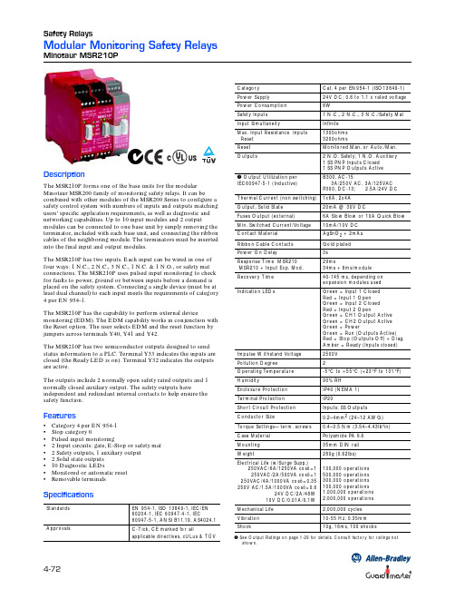
4-72Safety RelaysModular Monitoring Safety RelaysMinotaur MSR210PDescriptionThe MSR210P forms one of the base units for the modular Minotaur MSR200 family of monitoring safety relays. It can be combined with other modules of the MSR200 Series to configure a safety control system with numbers of inputs and outputs matching users’ specific application requirements, as well as diagnostic and networking capabilities. Up to 10 input modules and 2 outputmodules can be connected to one base unit by simply removing the terminator, included with each base unit, and connecting the ribbon cables of the neighboring module. The terminators must be inserted into the final input and output modules.The MSR210P has two inputs. Each input can be wired in one of four ways: 1 N.C., 2 N.C., 3 N.C., 1 N.C. & 1 N.O., or safety mat connections. The MSR210P uses pulsed input monitoring to check for faults to power, ground or between inputs before a demand is placed on the safety system. Connecting a single device (must be at least dual channel) to each input meets the requirements of category 4 per EN 954-1.The MSR210P has the capability to perform external devicemonitoring (EDM). The EDM capability works in conjunction with the Reset option. The user selects EDM and the reset function by jumpers across terminals Y40, Y41 and Y42.The MSR210P has two semiconductor outputs designed to send status information to a PLC. Terminal Y33 indicates the inputs are closed (the Ready LED is on). Terminal Y32 indicates the outputs are active.The outputs include 2 normally open safety rated outputs and 1 normally closed auxiliary output. The safety outputs haveindependent and redundant internal contacts to help ensure the safety function.Features•Category 4 per EN 954-1•Stop category 0•Pulsed input monitoring• 2 Input circuits: gate, E-Stop or safety mat • 2 Safety outputs, 1 auxiliary output • 2 Solid state outputs •10 Diagnostic LEDs•Monitored or automatic reset •Removable terminalsSpecificationsStandards EN 954-1, ISO 13849-1, IEC/EN 60204-1, IEC 60947-4-1, IEC60947-5-1, ANSI B11.19, AS4024.1ApprovalsC-Tick, CE marked for allapplicable directives, cULus & TÜV➊ See Output Ratings on page 1-29 for details. Consult factory for ratings notshown.Category Cat. 4 per EN954-1 (ISO13849-1)Power Supply 24V DC; 0.8 to 1.1 x rated voltage Power Consumption 8WSafety Inputs 1 N.C., 2 N.C., 3 N.C./Safety Mat Input SimultaneityInfinite Max. Input Resistance Inputs Reset 1300ohms 3200ohmsReset Monitored Man. or Auto./Man.Outputs2 N.O. Safety; 1 N.O. Auxiliary 1 SS PNP Inputs Closed 1 SS PNP Outputs Active ➊ Output Utilization per IEC60947-5-1 (Inductive)B300, AC-153A/250V AC, 3A/125VAC P300, DC-13; 2.5A/24V DC Thermal Current (non switching)1x6A, 2x4A Output, Solid State 20mA @ 30V DCFuses Output (external)6A Slow Blow or 10A Quick Blow Min. Switched Current/Voltage 10mA/10V DC Contact Material AgSnO 2 + 2mAu Ribbon Cable Contacts Gold plated Power On Delay3sResponse Time MSR210 MSR210 + Input Exp. Mod.29ms34ms + 6ms/module Recovery Time 40-145 ms, depending on expansion modules used Indication LEDsGreen = Input 1 Closed Red = Input 1 Open Green = Input 2 Closed Red = Input 2 OpenGreen = CH1 Output Active Green = CH2 Output Active Green = PowerGreen = Run (Outputs Active)Red = Stop (Outputs Off) + Diag.Amber = Ready (Inputs closed)Impulse Withstand Voltage 2500V Pollution Degree 2Operating T emperature -5°C to +55°C (+23°F to 131°F)Humidity90% RH Enclosure Protection IP40 (NEMA 1)T erminal Protection IP20Short Circuit Protection Inputs; SS Outputs Conductor Size0.2–4mm 2 (24–12 AWG)T orque Settings—term. screws 0.4–0.5 Nm (3.54–4.43lb²in)Case Material Polyamide PA 6.6Mounting 35mm DIN rail Weight280g (0.62lbs)Electrical Life (w/Surge Supp.)250VAC/6A/1250VA cosö=1250VAC/2A/500VA cosö=1250VAC/4A/1000VA cosö=0.35250V AC/1.5A/1000VA cosö=0.624V DC/2A/48W 10V DC/0.01A/0.1W 100,000 operations 500,000 operations 300,000 operations 100,000 operations 1,000,000 operations 2,000,000 operations Mechanical Life 2,000,000 cycles Vibration 10-55 Hz, 0.35mm Shock10g, 16ms, 100 shocksSafety Relays4-73Modular Monitoring Safety RelaysMinotaur MSR210PProduct SelectionDimensions—mm (inches) Block DiagramTypical Wiring DiagramsInputs Safety OutputsAuxiliary OutputsSolid State OutputsPower Supply Catalogue Number 1 N.C. or 2 N.C. or 3 N.C. or Safety Mat2 N.O.1 N.C.2 PNP24V DC440R-H23176Diagnostics – Red Stop LED blinksBlink RateDescription2Change in Y40/Y41/Y42 circuit during operation.3Fault in external feedback circuit Y1-Y2. Clear fault and cycle power to reset the module.ContinuousInternal fault in base or expansion module2S42Y1Y3142Y3224321423133S12S32S513Y42A1Y41Y40S41S31S11142413K1K2233132Y31Y3345 (1.77)99 (4.72)114.5 (4.5)Safety Mat and Dual Channel Safety Gate,Monitored Manual Reset, Monitored OutputTwo Triple Channel Inputs,Automatic Reset, Monitored OutputTwo Dual Channel Safety Gates,Monitored Manual Reset, No Monitored OutputT e r m i n a t i o n o r Active ClosedActive ClosedActive ClosedTwo Single Channel Safety Gates,Automatic Reset, No Monitored OutputActive Closed。
电子教程:CF210SP调频、调幅收音机套件

CF210SP 调频、调幅收音机套件的教学课件JC210SP 型收音机是新型的调频、调幅两波段收音机,调频波段采用CD9088的芯片,其采用贴片元气件SMT 封装,接收频率范围为76-108MHZ ,不仅能接收调频广播,还能接收校园广播和部分电视台的音频信号;调幅波段采用直放式集成电路TA7642,接收频率范围是525-1605KHZ ,具有电路简洁,装配成功率高,有较好的选择性等优点;功放电路采用TDA2822的专用功放集成电路,具有声音大,音质好等优点。
一、电路工作原理JC210SP 型调频、调幅收音机的原理电路图见图一所示。
1、调频(FM )部分CD9088是一块专用单片调频收音机芯片, 其外围电路简单,电路内置中频频率为70kHz 的锁相环系统,选择性由有源RC 滤波器实现,静音电路可抑制非中频信号和太弱的中频信号。
其特点如下:内含单声道收音机从射频输入到音频输出的所有功能电路,静音电路,内含自动频率控制系统可用于机械调谐,电源极性保护,工作电源电压可低至1.8V 。
调频信号由拉杆天线经C8、C10和L1的输入电路进入IC1的11、12脚混频电路,本振电 路采用的是可变电容器CA 、L2等元气件,可实现手动调台。
FM 广播信号和本振电路信号在IC1内混频产生70KHZ 的中频信号,经内部中频放大,中频限幅器,送到鉴频器检出音频信号,经内部环路滤波后由2脚输出音频信号。
电路中的R2、C2为静噪电路,3脚接的C4为音频环路滤波电容,6、8脚之间接的C13是中频反馈电容,7脚接的C14是低通电容器,8、9脚之间接的C17是中频耦合电容,10脚接的C12是限幅放大器的低通电容,13图一 JC210SP 型调频、调幅收音机的原理电路图脚接的C6为限幅器失调电压电容。
2脚输出的音频信号经过R6、C18耦合到功率放大集成电路TDA2822的输入端7脚,经过IC3(TDA2822)内部功率放大后由其1、3脚输出经过放大后的音频信号以推动扬声器工作,电路中的带开关电位器VOL 是用来控制电源的开和关,以及控制音量的大小。
自恢复保险丝中文资料及应用选型
动作原理
RF/WH 系列可恢复保险丝
的动作原理是一种能量的动态平衡,流过 RF/WH 系列元件的电流由于 RF/WH 系列
的关系产生热量,产生的热全部 或部分散发到环境中,而没有散发出去的热便
会提高 RF/WH 系列元件的温度。
正常工作时的温度较低,产生的热和散发的热达到平衡。RF/WH 系列元件处 于低阻状 态,RF/WH 系列不动作,当流过 RF/WH 系列元件的电流增加或环境温 度升高,但如果达到产生的热和散发的热的平衡时,RF/WH 系列仍不动作。当电 流 或环境温度再提高时,RF/WH 系列会达到较高的温度。若此时电流或环境温 度继续再增加,产生的热量会大于散发出去的热量,使得 RF/WH 系列元件温度骤 增,在此阶段,很小的温度变化会造成阻值的大幅提高,这时 RF/WH 系列 元件 处于高阻保护状态,阻抗的增加限制了电流,电流在很短时间内急剧下降,从而 保护电路设备免受损坏,只要施加的电压所产生的热量足够 RF/WH 系列元件 散 发出的热量,处于变化状态下 RF/WH 系列元件便可以一直处于动作状态(高阻)。 当施加的电压消失时,RF/WH 系列便可以自动恢复了。
型号如:KX60-050 最大工作电压为 60V,最大工作电流为 0.5A 应用范围: ADSL 设备中的自恢复保险丝的应用 自恢复保险丝在无线电产品,电池组,充电器产品中的应用 汽车电子及零部 件中的过流保护应用 遥控电动玩具车, 高低频电源充电器电动玩具,童车等电子玩具中的应用 卫星接受器 DVB 产品中的应用 自恢复保险丝在通信终端设备产品中的应用 电源供应器产品中的应用 家庭影院 / 扬声器 / 分频器 / 电磁负载 / 马达 / 吸尘器 六、自恢复保险丝的应用 1.镇流器 日光灯需要一个镇流器产生高电压和大电流来点着。镇流器控制日光灯的电 气特性。开灯时电子镇流 器在灯的两端产生高压冲击使灯点着,在电子镇流器
SYRis SY210NT 系列控制器 说明书 Version 2.3

SY210NT 系列控制器操作手册Version 2.3© 2005 by SYRIS Technology Corp.项目内容页次一.产品介绍 (1)二.设备连接图示说明 (2)三.设备初次使用设定 (6)四.控制器接线图 (10)五.系统主功能流程图 (14)一. 产品介绍:产品类别SY 系列产品主要为1. SY210NT 系列感应控制器2. SYRD 系列感应式卡片阅读机3. MDDIDO-1S 模块4. MDPRINT-1S 模块5. 感应卡系统架构图門區一門區二門區四門區三二. 设备连接图示说明:SY系列产品之间的设备连接可分为:1.控制器与管理计算机2.控制器与卡片阅读机3.控制器与扩充模块4.控制器内建输出入接点以下分述说明:1. 控制器与管理计算机控制器与管理计算机的连接是透过RS485接口传输,其连接编号为:控制器端 : 连接器代号----- M4( P1:蓝线4A- ; P2:紫线4A+ ; P5:黑线GND )管理计算机 : 25PIN连接器 --- 第一脚 : GND ; 第二脚: 4A+ ; 第三脚 : 4A-图示说明:一台管理计算机最多可接99台控制器,其连接为并接方式( 所有同色线接在一起 )从管理计算机延伸出的RS485传输线最长可至1 KM注意: RS485 传输线线材最好使用AWG18~22号计算机RS485传输用遮蔽对绞线(请洽当地线材供货商)2. 控制器与卡片阅读机控制器与卡片阅读机的连接是透过RS485接口传输,其连接编号为:控制器端 : 连接器代号----- M4( P3:灰线4R- ; P4:白线4R+ )卡片阅读机端 : 连接线代号 ----- 黄线 4R+ ; 绿线 4R- ;红线 DC+5~12V ; 黑线 DC0V图示说明:一台控制器最多可接8台卡片阅读机,卡片阅读机之连接为并接方式( 所有同色线接在一起 )从控制器延伸出的RS485传输线最长可至1 KM卡片阅读机注意: RS485 传输线线材最好使用AWG18~22号计算机RS485传输用遮蔽对绞线(请洽当地线材供货商)电源配置:(DC12V)1.控制器消耗电流:400mA/每一台2.卡片阅读机消耗电流:100mA/每一台3.打印机模块消耗电流:100mA/每一模块4.DIDO模块消耗电流:4DI4DO: 250mA/每一模块;8DI8DO:mA/每一模块16DI:mA/每一模块;16DO: mA/每一模块连接后的系统消耗电流(电压为DC12V)请自行依上述各单体消耗电流累加,并请选择适当的电源供应设备,提供系统正常运作所需。
S-22S12I10资料

Data Hold Characteristics
Table 5
Parameter Data hold voltage Data hold setup time Recovery time
Symbol VDH tCDH tR
Conditions CS≥VCC-0.2V, RECALL≥VCC-0.2V
Pin Assignment
18-pin DIP/SOP Top view A7(NC)* A4 A3 A2 A1 A0 CS GND STORE 1 2 3 4 5 6 7 8 9 18 17 16 15 14 13 12 11 10 VCC A6(NC)* A5 I/O4 I/O3 I/O2 I/O1 WE RECALL A0 to A7(A5)* I/O1 to I/O4 WE CS RECALL STORE GND VCC *( Address input Data input/output Write enable Chip select Recall Store Ground Power supply voltage (+5 V)
) is for the S-22H10 and S-22S10.
Figure 1
Seiko Instruments Inc.
1
PARALLEL NON-VOLATILE RAM S-22 Series
Block Diagram
Non-volatile E2PROM Memory Array A0(A0)* A1(A1)* A2(A2)* A3 A4 Row Selection Static RAM Memory Array Store Recall
High level input voltage 2 Low level input voltage 1
IR2101S中文资料

Data Sheet No. PD60043-NFeaturesHIGH AND LOW SIDE DRIVERProduct Summary 1IR2101/IR2102 (S)Absolute Maximum RatingsAbsolute maximum ratings indicate sustained limits beyond which damage to the device may occur. All voltage param-eters are absolute voltages referenced to COM. The thermal resistance and power dissipation ratings are measured under board mounted and still air conditions.Note 1: Logic operational for V S of -5 to +600V. Logic state held for V S of -5V to -V BS . (Please refer to the Design Tip DT97-3 for more details).Recommended Operating ConditionsThe input/output logic timing diagram is shown in figure 1. For proper operation the device should be used within the recommended conditions. The V S offset rating is tested with all supplies biased at 15V differential.IR2101/IR2102 (S)Static Electrical CharacteristicsV BIAS (V CC , V BS ) = 15V and T A = 25°C unless otherwise specified. The V IN , V TH and I IN parameters are referenced to COM. The V O and I O parameters are referenced to COM and are applicable to the respective output leads: HO or LO.Dynamic Electrical CharacteristicsV BIAS (V CC , V BS ) = 15V, C L = 1000 pF and T A = 25°C unless otherwise specified.IR2101/IR2102 (S)IR2101/IR2102 (S) Lead DefinitionsSymbol DescriptionHIN Logic input for high side gate driver output (HO), in phase (IR2101)HIN Logic input for high side gate driver output (HO), out of phase (IR2102)LIN Logic input for low side gate driver output (LO), in phase (IR2101)LIN Logic input for low side gate driver output (LO), out of phase (IR2102)V B High side floating supplyHO High side gate drive outputV S High side floating supply returnV CC Low side and logic fixed supplyLO Low side gate drive outputCOM Low side returnLead Assignments8 Lead PDIP8 Lead SOICIR2101IR2101S8 Lead PDIP8 Lead SOICIR2102IR2102SIR2101/IR2102 (S)Figure 1. Input/Output Timing DiagramHIN LINHO LOHIN LIN Figure 3. Delay Matching Waveform DefinitionsHIN LIN50%50%IR2101/IR2102 (S)IR2101/IR2102 (S)IR2101/IR2102 (S)IR2101/IR2102 (S)IR2101/IR2102 (S)IR2101/IR2102 (S)Case outlines。
海华Pro系列高速沙筒过滤器产品说明书

Your Hayward Pro Series high-rate sand filter is a high performance, totally corrosion-proof filter that blends superior flow characteristics and features with ease of operation. It represents the very latest in high-rate sand filter technology. It is virtually foolproof in design and operation and when installed, operated and maintained according to instructions, your filter will produce clear, sparkling water with only the least attention and care.HOW IT WORKSYour filter uses special filter sand to remove dirt particles from pool water. The filter sand is loaded into the filter tank and functions as the permanent dirt removing media. The pool water, which contains suspended dirt particles, is pumped through your piping system and is automatically directed by the patented filter control valve to the top of the filter tank. As the pool water is pumped through the filter sand, dirt particles are trapped by the sand bed, and filtered out. The cleaned pool water is returned from the bottom of the filter tank, through the control valve and back to the pool through the piping system. This entire sequence is continuous and automatic and provides for total recirculation of pool water through your filter and piping system.After a period of time, the accumulated dirt in the filter causes a resistance to flow, and the flow diminishes. This means it is time to clean (backwash) your filter. With the control valve in the backwash position, the water flow is automatically reversed through the filter so that it is directed to the bottom of the tank, up through the sand, flushing the previously trapped dirt and debris out the waste line. Once the filter is backwashed (cleaned) of dirt, the control valve is manually resequenced to Rinse, and then Filter, to resume normal filtering.INSTALLATIONOnly simple tools (screwdriver and wrenches), plus pipe sealant for plastic adapters, are required to install and/or service the filter.The filter system should be installed, not more than 6 feet above pool water level, on a level concrete slab, very firm ground, or equivalent, as recommended by your pool dealer. Position the filter so that the piping connections, control valve and winter drain are convenient and accessible for operation, service and winterizing.Assemble filter control valve to filter. Align the two (2) valve pipe connections, with O-rings in place, with the two openings in the side of the filter tank and press in firmly. Secure the assembly to the tank connections with the two bulkhead locknuts. Do not overtighten.1.2.IS210SV-99MODELS S210SV, S244SV23-1/2”(60 cm)35-3/4” (91 cm) S210SV 40” (102 cm) S244SVSPECIFICATIONSMODEL NUMBER S210SV S244SVEFFECTIVE FILTRATION AREAFT 22.23.14M 20.210.3GPM 4462LPM 167235PSI 23PSI 5050BAR 0.140.21BAR 3.453.45INCH 1818INCH 1818MM 457457MM 457457LBS 200300KGS 91136FILTER SAND**0.45-0.550.45-0.55DESIGNFLOW RATE*PRESSURE LOSS AT DESIGN FLOW RATE MAXIMUM WORKING PRESSURE REQUIRED CLEARANCESIDE ABOVEMEDIA REQUIREDTYPE AMOUNT PARTSModels S210SV, S244SV*Based on 20 GPM/ft.or 814 LPM/m (maximum allowable NSF rating).**Also known as No. 20 or No. 1/2 Silica Sand.NOTE:ANSI/NSPI-4 Article V, standard for above-ground and on-ground pools, advises that components such as the filtration system, pumps and heater be positioned so as to prevent their being used as a means of access to the pool by young children.REF.NO.1234567a 7b 89a 9b10a 10b 11a 11b 1213a 13b 1415161718192021NO.REQ’D.111111111111101111112212PART NO.ECX270861DEX2400S SX200Z5SX244K GMX600F GMX600NM SX210AA2SX244AA2SX244G SX210CD SX244CD1SX210CD2SX244CD2SX200Q SX240D SX240MACX3000Z2CX1100Z4SX200Z2SX180G SX180H SX200J SX220Z3SX244PSPX410X602S SX200Z4DESCRIPTIONPressure Gauge Manual Air Relief Cap O-Ring, 13/16”O.D.Top Closure Dome Valve/Tank O-Ring Flange Clamp (Valve-Tank)Filter Tank (S210S)Filter Tank (S244S)Top DiffuserTop Elbow Assembly (S210S)Top Elbow Assembly (S244S)Bottom Elbow Assembly (S210S)Bottom Elbow Assembly (S244S)Lateral (S210S)Lateral (S220S, S244S)Lateral Holder Assembly Plastic Air Tube (S210S)Plastic Air Tube (S244S)Air Tube Lock Screw Gasket Drain CapFilter Support Stand O-RingBulkhead FittingSlide Control Valve O-Ringa bAssemble pump and pump mounting base (if supplied) to the filter according to instructions packed with the base.Loading sand media. Filter sand media is loaded through the top opening of the filter.Remove the top diffuser from the internal diffuserelbow pipe and place flexible, automatic air relieftube to the side, out of the way, inside the tank.Cap the internal diffuser elbow pipe with protectioncap provided to prevent sand from entering it.It is good practice to fill tank approximately 1/2 waywith water to provide a cushioning effect when thefilter sand is poured in. This helps protect theunderdrain laterals from excessive shock. (Be surethe drain cap is securely in place on drain pipe. Applywrench to flats on pipe when tightening cap.) Note:Check to confirm all laterals are in the downposition before loading with sand. (See Figure Aon Page 2).Carefully pour in correct amount and grade of filtersand, as specified. Sand surface should be leveledand should come to about the middle of the filtertank. Use no more than the recommended amount ofsand.Remove protection cap from internal diffuser elbowpipe.Replace diffuser on internal diffuser elbow pipe,positioning automatic air relief tube through the holeprovided in the diffuser.Place valve flange clamp around neck of tank. Do notovertighten. Wipe filter flange clean.Insert top closure dome (with flange O-ring in place)into the tank neck. Place clamp around dome flangeand tank flange and tighten with screwdriver, tappingaround clamp with screwdriver handle to help seatflange clamp.Connect pump to control valve opening marked Port B (middle). Make return to pool pipe connection to control valve opening marked Port E (bottom) and complete other necessary plumbing connections, suction lines to pump, waste, etc.Make electrical connections to pump per pump instructions.To prevent water leakage, be sure drain cap is securely in place and all pipe connections are tight.INITIAL START-UP OF FILTERBe sure correct amount of filter sand media is in tank and that all connections have been made and are secure.Set filter control valve to BACKWASH*. (To prevent damage to control valve seal, always depress handle before turning).Prime and start pump according to pump instructions (be sure all suction and return lines are open), allowing the filter tank to fill with water. CAUTION: All suction and discharge valves must be open when starting the system. Failure to do so could cause severe personal injury and/or property damage.Once water flow is steady out the waste line, run the pump for at least 2 minutes. This initial backwashing of the filter is recommended to remove any impurities or fine sand particles in the sand media.Turn pump off and set valve to FILTER position (handle UP and locked) and restart pump. Your filter is now operating in the normal filter mode, filtering particles from the pool water.Adjust pool suction and return valves to achieve desired flow. Check system and filter for water leaks and tighten connections, bolts, nuts, as required.Note the initial pressure gauge reading when the filter is clean. (It will vary from pool to pool depending upon the pump and general piping system.) As the filter removes dirt and impurities from the pool water, the accumulation in the filter will cause the pressure to rise and flow to diminish. When the pressure gauge reading is 6-8 PSI(0.41-0.55 BAR) higher than the initial “clean” pressureyou noted, it is time to backwash (clean) the filter (see BACKWASH under Filter Control Valve Functions).NOTE: During initial clean-up of the pool water it may be necessary to backwash frequently due to the unusually heavy initial dirt load in the water.IMPORTANT: To prevent unnecessary strain on piping system and valving, always shut off pump before switching Filter Control Valve positions.To prevent damage to the pump and filter and for proper operation of the system, clean pump strainer and skimmer baskets regularly.FILTER CONTROL VALVE FUNCTIONSFILTER and BACKWASH selections are provided for all necessary operational functions.FILTER—Set valve to FILTER for normal filtering. Also use for vacuuming (handle in UP position).BACKWASH—For pressure cleaning filter (handle in DOWN position).VACUUMING—Vacuuming can be performed directly into the filter. Set valve in FILTER position.3. 4.a.b.c.d.e.f.g.h. 5.6. 7.1. 2.3.4. 5. 6.*NOTE:For new concrete or gunite pools, or where there is a large amount of plaster dust or debris—start filter in FILTER position (not BACKWASH) to prevent clogging of underdrain laterals.PROBLEM SOLVING LISTLOW WATER FLOW SHORT FILTER CYCLES POOL WATER WON’T CLEAR UPCheck skimmer and pump strainer baskets for debris.Check for restrictions in intake and discharge lines.Check for air leak in intake line (indicated by bubbles returning to pool). Backwash filter.Check for algae in pool andsuperchlorinate as required.Be sure chlorine and pHlevels are in proper range(adjust as required).Check surface of filter sandfor crusting or caking(remove 1”of sand ifnecessary).Check chlorine, pH and totalalkalinity levels and adjustas required.Be sure flow rate throughfilter is sufficient.Operate filter for longer periods.Be sure control valve is seton “Filter” position.1. 2. 3. 4.1.2.3.1.2.3.4.REMEDYPOOL CHEMISTRY GUIDELINESACTION REQUIRED TO CORRECT POOL CHEMISTRYTO RAISE TO LOWER SUGGESTED POOL CHEMISTRY LEVELSpHTOTAL ALKALINITY CHLORINE (UNSTABILIZED) CHLORINE (STABILIZED) CHLORINE STABILIZER (Cyanuric Acid)7.2 to 7.6100 to 130 ppm0.3 to 1.0 ppm1.0 to 3.0 ppm40 to 70 ppmAdd Soda AshAdd Sodium BicarbonateAdd Chlorine ChemicalAdd Chlorine ChemicalAdd StabilizerAdd Muriatic Acid or Sodium BisulphateAdd Muriatic AcidNo action - chlorine will naturally dissipateNo action - chlorine will naturally dissipateDilution - partially drain & refill pool with waterthat has not been treated with Cyanuric Acid.©1999 Hayward Printed in U.S.A.WINTERIZINGCompletely drain tank by unscrewing drain cap at base of filter tank. Leave cap off during winter. Drain filter control valve.Drain and winterize pump according to pump instructions. PLEASE REALIZE . . .Pure, clear swimming pool water is a combination of two factors—adequate filtration and proper water chemistry balance. One without the other will not give the clean water you desire.Your filter system is designed for continuous operation. However, this is not necessary for most swimming pools. You can determine your filter operation schedule based on your pool size and usage. Be sure to operate your filtration SERVICE & REPAIRSConsult your local authorized Hayward dealer or service center. No returns may be made directly to the factory without the expressed written authorization of Hayward Pool Products, Inc.system long enough each day to obtain at least one complete turnover of your pool water.To properly sanitize your pool, maintain a free chlorine level of 1 to 3 ppm and a pH range of 7.2 to 7.6. Insufficient chlorine or an out of balance pH level will permit algae and bacteria to grow in your pool and make it difficult for your filter to properly clean the pool water.Rev. 1/99。
全自动衬衫冷折装袋机使用说明书
全自动衬衫冷折装袋机Automatic Shirt Pocket Setter (MB1002B -1-S7300A-603P)使用说明书Instruction Manual常州智谷机电科技有限公司CHANGZHOU WISDOM &VALLEY ELECTRICAL TECHNOLOGY CO.,LTD在使用本设备之前请先阅读本使用说明书Please read the operation manual of the touch screen interface before using the device 请将本使用说明书放在便于查阅的地方保管Please keep this operation manual of touch screen interface in convenient placeforreference2020.03版本信息/Version感谢购买IMB工业用缝纫机。
在使用此机器之前,请仔细阅读以下的说明,这样可以更好地帮到您了解此机器的相关操作。
这些说明是根据现行的条例明确阐述了正确的工作方法。
Thank you for purchasing this industrial sewing machine from IMBBefore using this automatic unit,please read the following instructions,which will help you tounderstand how the machine operates.These instructions illustrate the correct working methods to comply with current regulations.在没有得到IMB授权许可的前提下,此说明书的任何部分是不可以被复制或者转录的。
说明书的内容可能被修改,而不需预先通知。
第7章 S5PV210微处理器简介(2014年4月2日)汇总
•if (TZPCR0SIZE(TZPC0) == 6‘b00_0000),这是 在iSRAM(0KB)中的非安全区域;
•if (TZPCR0SIZE(TZPC0) == 6‘b00_0001), 最小 安全区域是4KB;
第7章 S5PV210微处理器简介 2学时
本章主要内容 1、S5PV210 介绍; 2、S5PV210 引脚说明; 3、MEMORY MAP; 4、S5PV210 部分功能模块说明。
1
本章教学要求 了解 S5PV210 微处理器功 能特性,内部构成。
2
7.1 S5PV210
1、 S5PV210 简介
Ball
引脚名称
A1
VSS
A2
XMSMDATA_15
A3
XMSMIRQN
A4
XMSMADVN
A5
XMMC0DATA_1
A6
XMMC1DATA_2
后续略
33
3、引脚具体功能分配
引脚名称
XURXD_0 XUTXD_0 XUCTSN_0 XURTSN_0 XURXD_1 XUTXD_1
说明
SROM Bank 5 OneNAND/NAND Controller
and SFR MP3_SRAM output buffer
IROM
Reserved
IRAM
DMZ ROM
SFR region
备注
27
3、内部存储器地址映射
28
上图说明:
TZPCR0SIZE[5:0](TZPC0); (in TZPC SFR) (1)4K字节块; (2)推荐值: 6‘b00_0000 ~ 6’b10_0000;
VITSON产品说明书中文英文
深圳市慧拓鑫科技有限公司Shenzhen Hui Tuo Xin Technology Co., Ltd.产品资料Product information1、TOP电源防雷箱系列(TOP Power lightning protection box series) (1)2、TP 限压型电源防雷模块系列(TP Voltage limiting type power supply lightning protection module series) (8)3、TP直流电源防雷模块系列(TP DC power supply lightning protection module series) (14)4、TCP电源未端精细防护防雷器系列(TCP Power supply terminal fine protective lightning arrester series) (20)5、TDC 电源插座(TDC Power supply lightning protection socket series) (25)6、TV 视频防雷器系列(TV Video arrester series) (30)7、T 视频/射频防雷器系列(T Video / RF lightning arrester series) (36)8、TC控制线路防雷器系列( TC Control circuit lightning arrester series) (40)9、10/100M网络线路防雷器(10/100M Network circuit lightning arrester) (44)10、通讯专线防雷器(Communication line lightning arrester) (49)11、TT天馈线路防雷器系列(TT Antenna line arrester series) (53)1、TOP电源防雷箱系列(TOP Power lightning protection box series)产品介绍Product introductionTOP电源防雷箱系列依据IEC标准设计,8/20波形最大通流容量20KA-100KA,能对电源系统的浪涌电压进行有效的钳制,电源B、C、D级产品均具备。
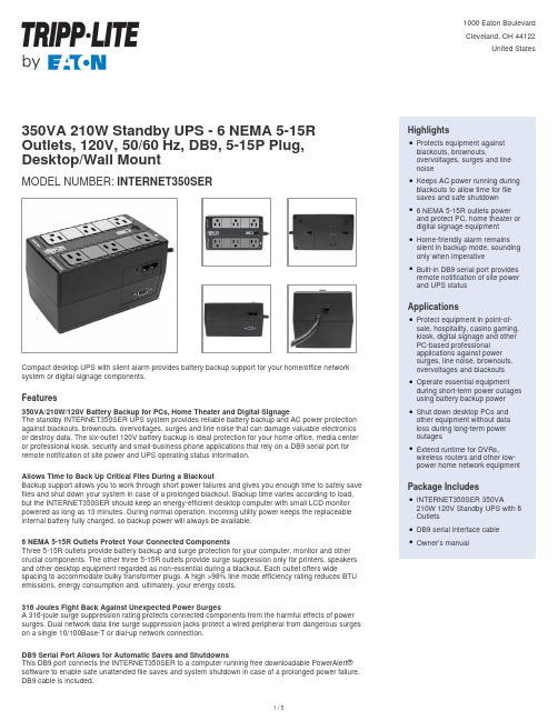
INTERNET350SER 350VA 210W 六口端口 Standby UPS 产品说明说明书
350VA 210W Standby UPS - 6 NEMA 5-15R Outlets, 120V, 50/60 Hz, DB9, 5-15P Plug, Desktop/Wall MountMODEL NUMBER:INTERNET350SERCompact desktop UPS with silent alarm provides battery backup support for your home/office network system or digital signage components.Features350VA/210W/120V Battery Backup for PCs, Home Theater and Digital SignageThe standby INTERNET350SER UPS system provides reliable battery backup and AC power protection against blackouts, brownouts, overvoltages, surges and line noise that can damage valuable electronics or destroy data. The six-outlet 120V battery backup is ideal protection for your home office, media center or professional kiosk, security and small-business phone applications that rely on a DB9 serial port for remote notification of site power and UPS operating status information.Allows Time to Back Up Critical Files During a BlackoutBackup support allows you to work through short power failures and gives you enough time to safely save files and shut down your system in case of a prolonged blackout. Backup time varies according to load, but the INTERNET350SER should keep an energy-efficient desktop computer with small LCD monitor powered as long as 13 minutes. During normal operation, incoming utility power keeps the replaceable internal battery fully charged, so backup power will always be available.6 NEMA 5-15R Outlets Protect Your Connected ComponentsThree 5-15R outlets provide battery backup and surge protection for your computer, monitor and other crucial components. The other three 5-15R outlets provide surge suppression only for printers, speakers and other desktop equipment regarded as non-essential during a blackout. Each outlet offers wide spacing to accommodate bulky transformer plugs. A high >98% line mode efficiency rating reduces BTU emissions, energy consumption and, ultimately, your energy costs.316 Joules Fight Back Against Unexpected Power SurgesA 316-joule surge suppression rating protects connected components from the harmful effects of power surges. Dual network data line surge suppression jacks protect a wired peripheral from dangerous surges on a single 10/100Base-T or dial-up network connection.DB9 Serial Port Allows for Automatic Saves and ShutdownsThis DB9 port connects the INTERNET350SER to a computer running free downloadable PowerAlert®software to enable safe unattended file saves and system shutdown in case of a prolonged power failure. DB9 cable is included.HighlightsProtects equipment againstblackouts, brownouts,overvoltages, surges and linenoiseqKeeps AC power running during blackouts to allow time for filesaves and safe shutdownq6 NEMA 5-15R outlets powerand protect PC, home theater or digital signage equipmentqHome-friendly alarm remainssilent in backup mode, sounding only when imperativeqBuilt-in DB9 serial port providesremote notification of site power and UPS statusqApplicationsProtect equipment in point-of-sale, hospitality, casino gaming, kiosk, digital signage and otherPC-based professionalapplications against powersurges, line noise, brownouts,overvoltages and blackoutsqOperate essential equipmentduring short-term power outages using battery backup powerqShut down desktop PCs andother equipment without dataloss during long-term poweroutagesqExtend runtime for DVRs,wireless routers and other low-power home network equipment qPackage IncludesINTERNET350SER 350VA210W 120V Standby UPS with 6 OutletsqDB9 serial interface cableqOwner’s manualqSpecificationsCombats Electromagnetic Interference That Can Harm EquipmentVarious electromagnetic and radio sources found in virtually every home and business can cause disruptive interference on the AC line. Known as EMI (electromagnetic interference) and RFI (radio frequency interference), this line noise is a common cause of performance problems and can lead to incremental hardware damage, data corruption and audio/video transmission problems. TheINTERNET350SER incorporates technology that filters out disruptive line noise so that it won’t affect your equipment.Home-Friendly Alarm and Diagnostic LEDs Keep You Informed 24/7The UPS remains silent in both line and battery backup modes. The alarm sounds only to warn you of a low battery or fault condition. A front-panel green LED indicates line/battery mode status, overloads and low/replace battery alert.Compact Housing Compatible with Easy Desktop or Wall-Mount InstallationThe space-saving ABS housing fits on a desktop, shelf or anywhere else convenient to your workstation or home theater. Keyhole mounting tabs on the rear allow easy wall-mount installation. The five-foot power cord with NEMA 5-15P plug connects to any compatible AC outlet.© 2023 Eaton. All Rights Reserved. Eaton is a registered trademark. All other trademarks are the property of their respective owners.。
WRV210_QSG_Simplified_Chinese

5 验证硬件安装
要对硬件安装进行验证,请完成以下工作: • 根据了解 WRV210,页码 1 中的介绍,检查 LED 的状态。 • 如果 LED 的显示状态异常,请检查电缆连接。
注意 如果需要帮助以解决某个问题,请访问思科精睿 (Cisco Small Business) 支持社区 (/go/smallbizsupport)。有关技 术文档和其他链接,请参阅快速索引,页码 12。
步骤 5 将电源适配器连接到路由器的 Power 端口,然后将另一端插入电源插 座中。
注意 请仅使用随路由器提供的电源适配器。使用其他电源适配器可能 会损坏路由器。
只要电源适配器连接正确,路由器前面板上的 Power LED 和 Internet LED 即会呈绿色亮起。
步骤 6 接通连接设备和宽带网络设备的电源。
8
思科精睿 (Cisco Small Business) WRV210 使用说明书
• WPA Enterprise:安全性较强,通过连接到路由器的 RADIUS 服 务器进行验证。可以选择 WPA Enterprise (TKIP 或 AES 加 密)、 WPA2 Enterprise (AES 加密)或 WPA2 Enterprise Mixed (TKIP 或 AES 加密)。
• Username 和 Password:输入您的 ISP 帐户的登录信息。
• PPTP Server 或 Authentication Server:输入您的 ISP 提供的 服务器 IP 地址或名称。
• Host Name 和 Domain Name:仅当您的 ISP (通常是电缆 ISP)要求时填写这些字段。
7
• Disable:禁用无线网络
BA-210SP Bassamp Cube 产品说明书

2TABLE OF CONTENTS:Important Safeguards and Precautions . . . . . . . . . . . . . . . . . . . . .3The T op Panel . . . . . . . . . . . . . . . . . . . . . . . . . . . . . . . . . . . . . . .4,5The Digital Eff e c t s . . . . . . . . . . . . . . . . . . . . . . . . . . . . . . . . . . . . .6Programming the Footswitch . . . . . . . . . . . . . . . . . . . . . . . . . . . . .7System Block Diagram . . . . . . . . . . . . . . . . . . . . . . . . . . . . . . . . .7T echnical Specifications. . . . . . . . . . . . . . . . . . . . . . . . .back coverTHIS EQUIPMENTHAS BEEN DESIGNED AND ENGINEERED TO PROVIDE SAFE AND RELIABLE OPERATION. IN ORDER TO PRO-LONG THE LIFE OF THE UNIT AND PREVENT ACCIDENTAL DAMAGES OR INJURY , PLEASE FOLLOW THESE PRECAUTIONARYGUIDELINES:CAUTION:TO REDUCE THE RISK OF ELECTRIC SHOCK, DO NOT OPEN CHASSIS; DO NOT DEFEAT OR REMOVE THE GROUND PIN OF THE POWER CORD; CONNECT ONLY TO A PROPERLY GROUNDED AC POWER OUTLET.WARNING:TO REDUCE THE RISK OF FIRE OR ELECTRIC SHOCK, DO NOT EXPOSE THIS EQUIPMENT TO RAIN OR MOISTURE.DO NOTEXPOSE THE UNIT TO SPLASHING OR DRIPPING LIQUID. DO NOTPLACE LIQUID FILLED OBJECTS ON THE UNIT.CAUTION:NO USER-SERVICEABLE PARTS INSIDE. REFER SERVICING TO QUALIFIED SERVICE PERSONNEL.CAUTION:OUR AMPLIFIERS ARE CAPABLE OF PRODUCING HIGH SOUND PRESSURE LEVELS. CONTINUED EXPOSURE TO HIGH SOUND PRESSURE LEVELS CAN CAUSE PERMANENT HEARING IMPAIRMENT OR LOSS. USER CAUTION IS ADVISED AND EARPROTECTION IS RECOMMENDED IF UNITIS OPERATED ATHIGH VOLUME.3IMPORTANT SAFEGUARDS AND PRECAUTIONS:All Ampeg products are designed for continuous safe operation.Abiding by the following rules can help prevent damage to your amplifier, yourself and others.•The amplifier is equipped with a three-pronged AC power cord. To reduce the risk of electrical shock, NEVER remove or otherwise attempt to defeat the ground pin of the power cord.•Connect the amplifier ONLY to a properly grounded AC outlet of the proper voltage for your amp.•Avoid sudden temperature extremes, rain and moisture.Also, avoid sudden and intense impact. (If the unit has been subjected to any of the preceding abuses, have it looked at by an authorized service center.)•Do not expose the unit to splashing or dripping liquid. Do not place liquid filled objects on the unit.•NEVER set the amplifier on a support that will not bear its weight.•Always keep the total speaker impedance at or above the rated load.•Unplug the amplifier before cleaning it. NEVER spray liquid cleaners onto the amplifier. Wipe it with a slightly damp-ened, lint-free cloth to remove dirt and film.•DO NOT use the amplifier if it has sustained damage to the chassis, controls, or power cord. Refer the unit to an authorized service center for inspection.•Prolonged exposure to high volume levels may cause per-manent hearing loss or damage. Such damage is progres-sive and irreversible!THE TOPPANEL:1. 0dB I N P U T :Connect your “passive” bass guitar here using a shielded instrument cable. This input is not padded and is best suited for basses without active electronics.2. -15dB I N P U T : Connect your “active” bass here using a shielded instrument cable. T h i s input is padded 15dB and is best suited for basses with active electronics and/or “hot”p i c k u p s .3. VOLUME: Use this control in conjunction with your instrument’s volume controls to adjust the level of the signal sent to the pre-amp. For the best signal to noise ratio and maximum headroom, start with this control at 5 or greater.4. STYLE:This five-position switch is used to control the tone of the amplifier. Experiment with the Style and other eq controls (#5,6,7)for the results which suit you best. The set-tings of the style control are as follows:5. LOW:This control is used in conjunction with the style control to adjust the low fre-quency level of the amplifier.6. MID:This control is used in conjunction with the style control to adjust the midrange level of the amplifier.7. HIGH:This control is used in conjunction with the style control to adjust the high fre-quency level of the amplifier.8. LEVEL:Use this control to adjust the level of the output signal from the amplifier. T h i s control also adjusts the signal level of the CD Inputs (#12), the Headphones jack (#13) and the Line Out jack (#15).9. EFFECTS SELECT :Use this control to select the desired digital effect. A listing of the effects is shown on page 6.10. EFFECTS A D J U S T :Use this control to adjust one of the parameters of the selected digital effect. A listing of the parameters for each of the effects is shown on page 6.4511. EFFECTS LEVEL: Use this control to adjust the level of the selected digital effect.12. CD INPUT:Use these RCA jacks to connect the line level (or headphones)output of a CD player, tape deck or rhythm machine to the amplifier.The inputs to these jacks are summed into a mono sig-nal which is fed into the BA210SP’s power amplifier.The signal level from these jacks is adjusted by the amplifier’s Level control (#8). If the signal from the source connect-ed to these jacks is too strong, use the output level control on the source to adjust the signal to obtain the proper level for a good mix.13. HEADPHONES:Use this jack to listen to the amplifier through a pair of stereo headphones. The internal speaker is dis-connected when the headphones jack is used.14. FOOTSWITCH:Use this jack to con-nect the supplied two button footswitch to the amplifier for remote control of the digi-tal effects. For information on program-ming the footswitch, see page 7.15. BAL. LINE OUT:This jack supplies a post-eq, balanced line level signal for con-necting to a house sound board, recording unit or external amplifier.16. POWER:Use this switch to turn the amplifier on or off. The adjacent LED will illuminate when the amplifier is turned on.17. A C L I N E C O R D (rear panel, not shown):This heavy duty, grounded, three wire power cord is to be plugged into a safely-wired, grounded, 120 volt, 60 cycle A C power outlet. DO N O T attempt to defeat the ground connection of this cable!If your amplifier was purchased outside of the United States, see the unit’s rear panel for its power and voltage ratings and follow the above guidelines.6THE DIGITAL EFFECTS:The BA-210SP features 15 built-in digital effects designed especially for the e the Effects Select control to choose one of these effects. The numbers that cir-cumscribe the control correspond to the “effects menu” below (and to the chart on the back of the amplifier). Each effect has a parameter which can be modified using the Adjust control. Use the Level control to mix in the desired amount of effect.BA115SP DSP Section – top panel#DESCRIPTIONADJUST0BYPASS - no effectsn/a 1CHORUS - deep, timed based, full of movement SPEED 2FLANGE - the classic whoosh of a good flangeSPEED 3PHASE SHIFTER - a 4-stage multiple-frequency phase shifter SPEED 4REVERB - adjustable from a tight room to a large hall ROOM SIZE 5OCTAVIDER - with a twist - smooth or with low growl TONE 6ECHO - multiple repeat echo DELAY TIME 7SLAPBACK - single repeat “slap”DELAY TIME 8FUNK WAH - the “quack” of a good envelope triggered filter THRESHOLD 9REVERSE WAH - envelope-triggered filter, swept high to low THRESHOLD 10CHORUS / ECHO / WAH - a “dreamy combination”THRESHOLD 11OCTAWAH - for when ya wanna get “really funky”THRESHOLD 12SVT - classic tube warmth, can get mild overdrive fatness GAIN 13SYNTH BASS 1 - a funky synthesized bass sound THRESHOLD 14SYNTH BASS 2 - an even funkier synthesized bass sound THRESHOLD 15SQUARE WAVE - heavily overdriven, smooth to sizzlingTONEEFFCTS MENUSYSTEM BLOCK DIAGRAM:Preset A Preset BPreset C Preset D7The BA-210SP allows you to save four DSP settings by means of the two button footswitch sup-plied with the amplifier. Use the following steps to store and recall four DSP s e t t i n g s :•Press the footswitch button until both LEDs are off – select an effect (bypass, “0”) – for reference,this shall be Preset A•Press the #1 button on the footswitch (the #1 LED illuminates and Preset A is stored) - select another effect (chorus, “1”) and adjust to taste – for reference, this shall be Preset B •Press the #2 button on the footswitch (the #2 LED illuminates and Preset B is stored) - select another effect (octawah, “11”) and adjust to taste – for reference, this shall be Preset C •Press the #1 button on the footswitch again (the #1 LED turns off and Preset B is stored) - select another effect (SVT , “12”) and adjust to taste – for reference, this shall be Preset D•Press the #2 button on the footswitch again (both LEDs are off and Preset D is stored) - Preset A is automatically recalled – without changing the setting of the Effects control. Selection of the e f fects is now controlled by the footswitch.NOTE: The footswitch presets will be retained within the amplifier even after turning the amplifier off, until the above steps are repeated using different effects settings.PROGRAMMING THE FOOTSWITCH:TECHNICAL SPECIFICATIONS:OUTPUT POWER RATING220 Watts at 4 ohms @5% THDCD Input: 7.75V RMSLINE OUT LEVEL 1.78VRMSHEADPHONE OUT LEVEL900mV RMSGAIN41dB (input to speaker out, tones @5)5 = -6dB @50Hz and belowLOW40dB range @50HzMID30dB range @500HzHIGH40dB range @10kHzPiezo tweeter230VAC, 50/60Hz, 320VASIZE AND WEIGHT21” W x 21” H x 15-1/2” D; 86 lbs.。
