KANON扭力批说明书
英格索兰扭力扳手说明书
英格索兰扭力扳手说明书
(1)所选用的扭力扳手的开口尺寸必须与螺栓或螺母的尺寸相符合,扳手开口过大易滑脱并损伤螺件的六角。
(2)为防止扳手损坏和滑脱,应使拉力作用在开口较厚的一边,这一点对受力较大的活动扳手尤其应该注意,以防开口出现“八”字形,损坏螺母和扳手。
(3)扭力扳手是按人手的力量来设计的,遇到较紧的螺纹件时,不能用锤击打扳手;除套筒扳手外,其它扳手都不能套装加力杆,以防损坏扳手或螺纹连接件
(4)扭力扳手使用时,当听到“啪”的一声时,此时是最合适。
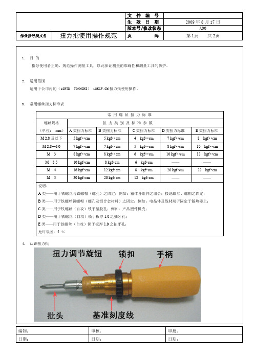
扭力批使用操作规范
的方式); ③ 如果逆时针转动扭力批,能松动被测螺丝,则判定被测螺丝扭力符合要求;如果不能松动被测螺丝,则判定被测螺丝上的
太紧,高于扭力标准要求。 6.4 判定; 6.4.1 顺时针转动扭力批不能转动螺丝,逆时针转动扭力批可以松动螺丝,则判定被测螺丝扭力符合标准要求; 6.4.2 顺时针转动扭力批可以转动螺丝,则判定被测螺丝扭力低于标准要求; 6.4.3 顺时针转动扭力批不能转动螺丝,逆时针转动扭力批不能松动螺丝,则判定被测螺丝扭力超过标准要求;
作业指导类文件
扭力批使用操作规范
文件编号 生效日期 版本号/修改状态
页
码页 共 2页
1. 目 的 指导使用者正确、规范操作测量工具,以此保证测量的准确性和测量工具的防护。
2. 适用范围 适用于公司内的(12RTD TOHNCHI) 12KGF.CM 扭力批使用操作。
3. 常用螺丝扭力标准表
常用螺丝扭力标准
螺丝规格
扭力类别及标准参数
(单位: mm) A 类扭力标准 B 类扭力标准
C 类扭力标准 D 类扭力标准
E 类扭力标准
M 2.8 及以下
5 kgf••cm
5 kgf••cm
4 kgf••cm
7 kgf••cm
8 kgf••cm
M 2.8—3.0
7 kgf••cm
5. 操作方法
5.1 根据测试螺丝槽的大小,将扭力批换用合适的批头;以批头放入螺丝槽转动不会打滑为准;
5.2 右手握住扭力批手柄,检查扭力调节旋钮是否可以转动,如不能转动,检查扭力批锁扣内侧白色原点有无对准“FREE”,如果 没有,则顺时针转动锁扣,使其对准“FREE”;
扭力扳手 说明书
扭力扳手的使用说明书扭力扳手应用范围较广,在加固扭力时,只需要设定其要求值便可进行操作.相对来讲比较简单.首先在扭距扳手上设定所需扭距值(由弹簧套在顶杆上向扭距释放关节施压),锁定扭距扳手开始拧紧螺栓,当螺栓达到扭距值后(当使用扭力大于弹簧的压力后)会产生瞬间脱节的效应.在产生脱节效应的瞬间发出关节敲击扳手金属外壳所发出的"卡塔"声.由此来确认达到扭距值的提醒作用.(其实就象我们手臂关节成15度弯曲放在铁管里瞬间申直后会碰到钢管的原理一样).了解各种扭力扳手的原理和各部分的作用还不够, 一个合格的技术操作?者还需要知道各种扭力扳手的用途, 会合理地选择适当的量具 .扭力表用於对需要观察其在施力过程中的力值变化且不确定所需要的力值大小的测量和检定.扭力批一般用於较小扭力值的测量,通常不会大於20kg.1.在扭力扳手的使用中,首先要根据测量部品的要求选取适中量程,所测扭力值不可小於扭力器在使用中量程的百分之二十,太大的量程不宜用於小扭力部品的加固,小量程的扭力器更不可以超量程使用2.在使用扭力扳手时,先将受力棘爪连接好辅助配件(如套筒,各类批嘴),确保连接已经没问题.在加固扭力之前,设定好需要加固的力值, 并锁好紧锁装置, 然后调整好方向转换钮到加力的方向3.测量时,手要把握住把手的有效范围,沿垂直於管身方向慢慢地加力直至听到到达已设定的量值后发出的声音.在施力过程中,按照国家标準仪器操作规范, 其垂直度偏差左右不应超过10度.其水平方向上下偏差不应超过3度,我厂在使用过程中操作人员应保证其上下左右施力范围均不超过15度4.為了不使测量结果因水平和垂直方向上的偏差而產生影响,在测量时,应在加力把持端上施加一个垂直向下的稳定力值.5.扭力扳手的读数:1)如果是带表扭力仪器.直接读取指针所指示的数据為测量数据值.2) 如果是套筒加副刻度指示器. 应先读取主刻度上的刻度值, 再加上副刻度或微分筒上的刻度值之和為测量数据值.本文由-广东仪器网-检测(测试)仪器展示站点-提供。
扭力扳手GARANT
扭力扳手使用说明书亲爱的用户,你的选择非常正确。
购买我们的产品将使你事半功倍。
每个GARANT牌扭力扳手因其高精确度和可靠性而与众不同。
它是用来拧紧螺丝的,且在出厂前刻度都已校准完好。
为了使扭力扳手发挥其最大功效,本说明书附上所有使用安全事项和其他信息。
应该按照以下的说明使用扭力扳手。
所有由于用户的不当使用而造成的人身伤害或材料损害都应由使用者自己承担。
使用前,检查倒扣释放的正确设置,以及插口/或插入工具的恰当基座。
安装好工具后,它就不会滑出螺钉接口。
否则你会面临人身杀害和/或材料损害。
为了防止不恰当的载入信息传输,你不该使用万向接头或万向扩充套件。
有可能利用扳手来拧松螺丝接口。
然而,当使用时,不要超过最大的扭力刻度(比如,当试图拧松生锈的螺丝)。
用力过大可能会损害扭力扳手从而导致扭力不准确。
扭力扳手是校准型的手持工具,必须小心谨慎。
因此,你应该避免超过正常使用范围外的机械,化学或热应力扭力扳手不允许当锤子用。
这会造成事故和损害。
极端的气候条件(冷,热,湿度)可能会影响它的精准度。
当使用插口/或插入工具,总是确保它们符合标准并有正确的形状和大小来拧紧螺纹接口。
此外,使用过的插口/或插入工具并没加载到最大许可值。
这个数值可能小于倒扣释放。
自制的特殊工具可能存有潜在危险。
无视这种警告会导致人身伤害和/物质损坏。
脱扣精度容差在开启方向(顺时针)为±3%。
所有扭力扳手都有可调刻度以及弥合差距释放:一旦达到预先设定的值,是能感觉到和听到的。
当扭力值低。
扭力扳手操作指导书
扭力扳手操作指导书【产品名称:扭力扳手】操作指导书注意事项:1-本文档为扭力扳手操作指导书,旨在指导用户正确使用和维护扭力扳手。
2-在使用扭力扳手之前,请仔细阅读本指导书,并按照操作步骤进行实施。
3-若您在操作过程中遇到问题,请参考本指导书的故障排除部分,在解决问题后再次进行操作。
一、产品概述1-扭力扳手是一种专门用于调整和控制螺栓拧紧扭力的工具,广泛应用于机械制造、汽车维修等领域。
2-扭力扳手的主要组成部分包括手柄、扭力调节装置和扭力指示装置。
二、使用前准备1-仔细阅读产品说明书,了解产品的特点和性能要求。
2-检查扭力扳手的外观是否完好,有无明显损坏。
3-检查扭力扳手的扭力调节装置和扭力指示装置,确保其正常工作。
三、操作步骤1-确定需要拧紧的螺栓规格和扭力要求。
2-使用提供的螺栓拧紧力矩表,确定需要设置的扭力数值。
3-根据扭力数值,使用扭力调节装置调整扭力扳手的扭力大小。
4-将扭力扳手固定在需要拧紧的螺栓上。
5-用手握住扳手手柄,用适当的力量旋转手柄,直到扭力指示装置指示达到设定的扭力数值。
6-如果需要多次拧紧螺栓,请重复以上步骤。
四、维护保养1-每次使用后,用干净的布擦拭扭力扳手的表面,确保其干燥无尘。
2-检查扭力扳手的各个部件是否存在松动或损坏,如有问题请及时修理或更换。
3-定期对扭力扳手进行校准,以确保其扭力准确可靠。
4-在长时间不使用扭力扳手时,应存放在干燥、通风的地方,避免受潮或受热。
五、故障排除常见故障及解决方法:1-扭力扳手无法调节扭力:检查扭力调节装置是否损坏,如有损坏请更换。
2-扭力指示装置不准确:检查扭力指示装置是否松动或损坏,如有问题请修理或更换。
【附件】附件一:螺栓拧紧力矩表【法律名词及注释】1-扭力:物体周围绕轴线旋转的力矩。
2-扭力调节装置:用于调整扭力扳手的扭力大小的装置。
3-扭力指示装置:用于指示扭力扳手当前扭力数值的装置。
KANON中村扭力计
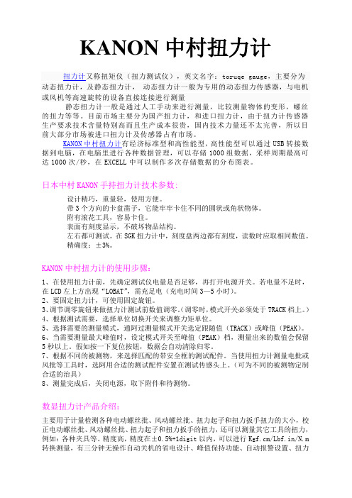
KANON中村扭力计扭力计又称扭矩仪(扭力测试仪),英文名字:toruqe gauge,主要分为动态扭力计,及静态扭力计,动态扭力计一般为专用的动态扭力传感器,与电机或风机等高速旋转的设备直接连接进行测量静态扭力计一般是通过人工手动来进行测量,比较测量物体的变形,螺丝的扭力等等。
目前市场主要分为国产扭力计,和进口扭力计,由于扭力计传感器生产要求技术含量特别高而且生产成本很贵,国内技术力量还不太完善,所以目前大部分市场被进口扭力计及传感器占有市场。
KANON中村扭力计有经济标准型和高性能型,高性能型可以通过USB转接数据到电脑,在电脑里进行各种数据管理,可以存储1000组数据,采样周期最高可达1000次/秒,在EXCELL中可以制作多次存储数据的分布图表。
日本中村KANON手持扭力计技术参数:设计精巧,重量轻,使用方便。
带3个方向的卡盘凿子,它能牢牢卡住不同的圆状或角状物体。
附有滚花工具,容易卡住。
表面有刻度显示,不破坏物品结构。
左右都可测试。
在SGK扭力计中,刻度盘两边都有刻度,读数时应取相同数值。
精确度:±3%。
KANON中村扭力计的使用步骤:1、在使用扭力计前,先确定测试仪电量是否足够,再打开电源开关。
若电量不足时,在LCD左上方出现“LOBAT”,需充足电(充电时间3—5小时)。
2、要固定扭力计,可使用固定旋钮。
3、调节调零旋钮来做扭力计测试前数值调零。
(调零时,模式开关必须处于TRACK档上。
)4、根据测试需要,选择单位切换开关来调整力矩单位。
5、选择需要的测量模式,通阿过测量模式开关选定跟随值(TRACK)或峰值(PEAK)。
6、当需要测量最大峰值时,设定模式开关至峰值(PEAK)档,测量出来的数值会保留5秒以上。
假如按一下复位按钮,数据会自动清除归零。
7、根据不同的被测物,来选择匹配的带安全框的测试配件。
当使用扭力计测量电批或风批等工具时,选阿用合适的测试配件安置在测试传感头上。
【精品】日本东日扭力扳手Tohnichi
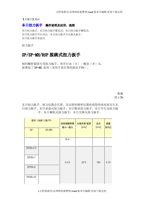
【关键字】精品东日扭力扳手操作说明及应用、选型东日扭力扳手,东日扭力扳手数显式,东日扭力扳手棘轮式,东日扭力扳手开行动式,东日扭力扳手可交换头扳手,东日扭力扳手表盘式扭力扳手SP/SP-MH/RSP脱跳式扭力扳手相同螺栓紧固专用扭力扳手。
带开行动(S)/梅花(R)头。
新增加了SP-MH 系列(采用不易打滑的滚花手柄)。
准确度±3%东日扭力扳手,扭力仪器总代理,北京朗科精密仪器欢迎您的来电张先生东日扭力扳手,东日表盘式扭力扳手,东日数显扭力扳手,东日开行动扭力扳手,东日棘轮式扭力扳手,东日交换头扭力扳手。
东日扭力扳手,扭力仪器总代理,北京朗科精密仪器欢迎您的来电张先生东日扭力扳手,东日表盘式扭力扳手,东日数显扭力扳手,东日开行动扭力扳手,东日棘轮式扭力扳手,东日交换头扭力扳手。
DB/DBE/DBR直读式扭力扳手检查用扭力扳手的基本型。
不受握持位置的影响。
(DBE:带加长手柄、DBR:机械加力型)表盘式清晰直观,适用于测定作业。
(-S:带记忆指针)准确度±3%注1 带记忆指针的型号后为“-S”。
注2 DBR 使用绞盘和手扳葫芦加力。
注3 DBR 为定制产品。
注4 □ 25.4 以上的方形驱动头请使用通孔套筒。
东日扭力扳手,扭力仪器总代理,北京朗科精密仪器欢迎您的来电张先生东日扭力扳手,东日表盘式扭力扳手,东日数显扭力扳手,东日开行动扭力扳手,东日棘轮式扭力扳手,东日交换头扭力扳手。
CEM3-G数字式扭力扳手紧固数据用LED 和LCD 组合显示,最大存储数为999 个。
准确度±1%注1 全长指本体的长度。
注2 交换头的详细内容请参见P38 ~ 41。
注3 可使用DFS 方便地进行简单的统计处理。
(参见P61)注4 使用红外线输出时请参见R-DT999。
(参见P59)注5 使用USB 进行通信时,需要专用电缆(No584)(选购件)。
注6 交换头PH(P41)的有效长度差异大,不可使用。
1 2英寸数字扭力适配器说明书

1/2"Drive Digital TorqueAdapterWhen unpacking your new digital torque adapter and related parts &accessories,please inspect it carefully for any damage that may haveoccurred during transit.If you have any questions,or require assistance with damaged or missing parts,please contact our factorycustomer servicedepartmentat:1-800-386-0191Pleasehavethe serialnumber,modelnumberand dateofpurchaseavailableforreferencewhencalling.This instruction manual is intended for your benefit.Please read and follow the safety,installation,maintenance and troubleshooting steps described within to ensure your safety and satisfaction.The contents of this instruction manual are based upon the latest product information available at the time of publication.Due to continuing improvements,actual product may differ slightly from the prod-uct described herein.Tools required for assembly and servicing are not included.INTRODUCTIONAfter opening the carton,unpack your new digital torque wrench adapter and related parts &acces-sories.Please inspect it carefully for any damage that may have occurred during transit.Please check it against the photograph on carton.If any parts are missing,please call factory customer ser-vice at 1-800-386-0191.UNPACKING &INSPECTIONDo not operate this tool if damaged during shipment,handling or misuse.Do not operate the tool until the parts have been replaced or the fault rectified.Failure to do so may result in serious per-sonal injury or property damage.All damaged parts must be repaired or replaced asneeded prior to operating this tool.Check to see that all nuts,bolts and fittings are secure before putting this tool into service.If you have any questions,or require assistance with damaged or missing parts,please contact our factory customer service department at:1-800-386-0191Please have the serial number,model number and date of purchase available for reference whencalling.WARNING -RISK OF FLYING PARTICLESREAD THIS MANUAL COMPLETELY BEFORE USING THE DIGITAL TORQUE ADAPTER•To insure accuracy,work must not move in angle mode.•For personal safety and to avoid wrench damage,follow good professional tool and fas-tener installation practices.•Periodic recalibration is necessary to maintain tool accuracy.USERS AND BYSTANDERS SHOULD ALWAYS WEAREYE PROTECTION•Besure all components,including adapters,extensions,drivers and sockets are rated to match or exceed the torque being applied with tool.•Observe all equipment,system and manufacturer’s warnings,cautions and procedures when using this adapter•Always use the correct size socket for the fastener being torqued.•Do not use damaged sockets,showing signs of wear or cracks.•Always replace damaged fasteners before applying torque.WARNING -Electrical Shock Hazard•Electrical shock can cause injury.•Plastic handle is not insulated.•Do not use on live electrical circuits.Over-torquing can cause breakage.An out of calibration torque wrench can cause part or tool breakage.Broken hand tools,sockets or accessories can cause injury.Excess force can cause crow foot or flare nut wrench slippage.IMPORTANT SAFEGUARDSIMPORTANT SAFEGUARDSto applying torque.•Never use this digital torque adapter to loosen fasteners as damage may occur.•Do not exceed the rated maximum torque value for the digital torque adapter as break-age and/or a loss of accuracy could occur.•Always verify the calibration of the digital torque adapter if you know or suspect its capac-ity has been exceeded.•Always pull-do not push-on the drive tool(ratchet)handle that is connected to the digi-tal torque adapter.•Adjust your stance to prevent a possible fall while applying torque.•Apply torque slowly and grasp the center of the handle.Do not apply load to the end ofthe handle.•Avoid applying excessive torque,turn the ratchet slowly and steadily as you apply torque.Pay attention to the LED light and sound indicators.•Never submerge the digital torque adapter in water or any other liquid.•If the tool gets wet,immediately wipe it dry with a soft,clean towel.•Do not expose this wrench to dust or sand as this could cause serious damage.•Use the digital torque adapter only for its intended purpose as described in this manual.•Do not use the digital torque adapter if it is not working properly or if it has suffered anydamage.•Do not disassemble the digital torque adapter.•Do not expose the digital torque adapter to extreme temperatures,humidity,direct sun-light.•Do not shake violently or drop digital torque adapter.•Do not use this tool as a hammer.•Position batteries in proper polarity.•Do not mix batteries of different type.•Never clean the digital torque adapter with soap or solvents.•Use a soft,dry,clean cloth to clean the digital torque adapter and LCD panel.•Do not apply excessive force to the LCD display panel.•Store in a clean dry place.•Keep this tool away from magnets.PRODUCT SPECIFICATIONSDrive size:1/2inchAccuracy:CW:±1%CCW:±2%Memory presets:10Display resolution:0.1NmOperation mode:Peak/TraceUnit selection:kg-cm,kg-m,lb-in,lb-ft,N-mBattery:(1)DC3V,CR2032Ambient temperature range:Operating:-10°C–60°C(13.9°F–139.9°F)Storage:-20°C-70°C(-4°F–157.9°F)Auto shut-off:80secondsTorque range:30-150Ft-lbs(41-203N-m)PRODUCT FEATURES•Digital torque readout.•Selectable for five torque units of measure:lb-ft,lb-in,kg-cm,kg-m and N-m.•+/-1%CW and +/-2%accuracy•Clockwise (CC)and counterclockwise (CCW)operation indicated on display.•Peak torque hold mode and Tracking torque mode selectable.•White LED backlight for easy reading.•Reverisble LCD display viewing orientation.•Multiple preset torque value indicators:audible buzzer,vibration alarm,red LED warning light.•Displays percentage of preset torque value attained.•Power saving automatic sleep mode activates after 3minues of inactivity.•Uses one (1)DC 3V,CR2032battery.•Batteries,storage case and calibration adapter included.displaybacklight barMain keyboardCONTROLSThe Titan Digital Torque Adapter displays fastener torque specification settings,torque readings and peak hold measurements.Mode key Warning buzzerpreset torque battery icon value of measure LCD DISPLAY INDICATORSWhen battery voltage drops below 2.6volts,a low battery warning icon willappear on the LCD display.When the battery voltage drops below 2.4volts,the low battery warning icon will begin to flash,indicating that immediate battery replacement isrequired.LOW BATTERY VOLTAGE INDICATIONBattery voltage under 2.4V POWERING ON DIGITAL TORQUE ADAPTERPress Mode button to turn digital torque adapter on and activate auto-zeroing process.Auto-zeroing processNormal mode(Preset number 0shown)CAUTION:Make sure the displayed applied torque value is zero during the auto-zeroing period.Otherwise a torque offset will be included.Select 1of 10user programable memory presets.SELECTING MEMORY PRESETSSETTING PRESET VALUES4.Five different unit selections are available:kg-cm,k-gm,in-lb,ft-lb,and N-m.SELECTING UNITS OF MEASURENOTE:When you change units,any target torque setting you have already entered will now be displayed in the new unit value.SELECTING PEAK HOLD/TRACKING MODESPressIn Track mode -The display will register “real-time”torque as it is applied.This is useful when you are able to observe the digital display while applying torque to a fastener.Watching the torque value increase can assist you in applying torque evenly and safely,especially as you approach your target torque setting.FullyreleaseDisplay retains peak torque achieved.PEAK HOLD MODE OPERATIONPeak Hold ModePercent of Target torqueApplytorque activatesRelease torque to zero-out torquereading and then apply torque again.Select pre-setting:200kg-cm(in this example)Applytorque and hold2sec.Toggle screen from Auto mode to Manual mode.Continue applying torque until preset torque value In Peak hold mode,the digital display shows the maximum torque applied,which can be helpful for verifying that the correct torque was applied when the digital display is not visible during use.This mode is also handy when using the adapter to calibrate a torque wrench.TRACKING MODE OPERATIONTracking ModeAt50%of Target torque:•Percentage of preset torque value is displayed•Buzzer sounds:Bi---Bi---Bi---•Select pre-setting:200kg-cmApply torque to reach preset torque value(200kg-cm in this example)At70%of target torque:At90%of target torque:At100%of target torque:•Percentage of preset torque value is displayed•Buzzer sounds:Bi-Bi-Bi-Bi•Red LED flashes:alert•Percentage of preset torque value is displayed•Buzzer sounds:BiBiBiBiBiBiBi•Percentage of preset torque value is displayedApplytorqueApplytorqueApplytorqueIn Tracking mode,the display will register torque as it is applied in real-time.This allows you to observe the digital display while applying torque to a fastener.Watching the torque value increase can assist you in applying torque evenly and safely,especially as you approach your target torque setting.Press and hold Mode button for 2seconds to turn unit off.NOTE:This tool will automatically enter sleep mode after 3minutes of inactivity.BATTERY INSTALLATION AND REPLACEMENT POWERING OFF DIGITAL TORQUEADAPTERPress and for 2seconds to toggle the orientation of the display readout.CHANGING ORIENTATION OFDISPLAYPress1.Requires one (1)DC 3V,CR2032.2.Unscrew battery cover fastener with a jewelers’phillips screwdriver.3.Remove the battery cover.4.Remove the old battery.5.Clean battery terminals.6.Install fresh battery in the digital torque adapter (with the “+”sign end facing upward).7.Replace the battery cover and screw tight.Note•Remove battery if stored for a long period of time.•Oil,water,dirt and sweat can prevent a battery’s terminals from making electrical contact.Wipe both terminals before installing batteries.Battery disposalOnly dispose of battery when fully discharged.DO NOT dispose of battery in a fire.Dispose of expended batteries andpackagingmaterialsinan environmentallyresponsiblemanner.1.Set your torque wrench to a value of approxi-mately 25%of its maximum capacity.Forexample,if your torque wrench has a maximumcapacity of 150lb-ft,set it to 40lb-ft.2.Program the digital torque adapter for a torquevalue that matches the torque wrench setting.In our example,you would set the adapter for40lb-ft.Ensure the adapter is in the “peak”mode as this will make it easy to referenceactual torque versus the torque indicated onthe wrench.3.Connect the pre-set torque wrench and theincluded calibration adapter to the digital torqueadapter.Secure the calibration adapter in abench vise.Ensure the calibration adapter issecurely tightened in the vise.4.Turn the torque wrench smoothly and steadily,applying torque to the calibration adapter untilyour torque wrench reaches the preset value,either by “clicking”(micrometer style torquewrench),or displaying the desired setting(digital or dial torque wrench).5.Read the peak torque value shown on the digi-tal torque adapter.Adjust your torque wrenchand repeat the procedure until the trquewrench and digital torque adapter show identi-cal torque values.DisposalDo not dispose of this device in normal domestic waste.Observe the currently valid regulations.In case of doubt,consult your waste disposal facility.CALIBRATING A TORQUE WRENCH USING DIGITAL ADAPTERIMPORTANT -Service,repair and calibration are to be performed by Star-Asia USA,LLC only.Cali-bration by the user is recorded in the wrench and voids factory certification.Contact Star-Asia USA,LLC for information on calibration service.PLEASENOTEUSER QUICK REFERENCE GUIDEMeasure Torque Presetting Target Torque90DAY LIMITED WARRANTY-STAR ASIA-USA,LLC POWER TOOLSStar Asia-USA,LLC(hereinafter“seller”)warrants to the original purchaser only,that this product will be free from defects in material or workmanship for a period of one year from date of purchase for home domestic use. Warranty PerformanceWarranty coverage is conditioned upon purchaser furnishing seller or its authorized service center with adequate written proof of the original purchase date.Products returned,freight prepaid and insured,to our factory or to an Authorized Service Center will be inspected and repaired or replaced,at seller‘s option,free of charge if found to be defective and subject to warranty.Defective parts not subject to normal wear and tear will be repaired or replaced,at our option during the above stated warranty periods.In any event,reimbursement is limited to the pur-chase price paid.Other than the postage and insurance requirement,no charge will be made for repairs or replacements covered by this warranty.Under no circumstances shall the manufacturer bear any responsibility for loss of the unit,loss of time or rental,inconvenience,commercial loss or consequential damages.There are no warranties which extend beyond the description of the face hereof.ExclusionsThis warranty does not cover parts damaged due to normal wear,abnormal conditions,misapplication,misuse, abuse,accidents,operation at other than recommended pressures or temperatures,improper storage or freight damage.Parts damaged or worn by operation in dusty environments are not warranted.Failure to follow recom-mended operating and maintenance procedures also voids warranty.Additional items not covered under this warranty:product failure caused by rain,excessive humidity,corrosive environments or other contaminants;cosmetic defects that do not interfere with product‘s functionality.This warranty shall not apply when:the product has been used for commercial or rental purposes;defects in mate-rials or workmanship or damages result from repairs or alterations which have been made or attempted by others or the unauthorized use of nonconforming parts;this damage is due to abuse,improper maintenance,neglect or accident;or the damage is due to use of the product after partial failure or use with improper accessories.Warran-ty does not apply to accessory items such as batteries.Seller will not be liable for:labor charges,loss or damage resulting from improper operation,maintenance or repairs made by persons other than a Star Asia-USA,LLC Authorized Service Center.The use of other than genuine Star Asia-USA,LLC Repair Parts will void warranty.Warranty DisclaimersNO WARRANTY,ORAL OR WRITTEN,OTHER THAN THE ABOVE WARRANTY IS MADE WITH REGARD TO THIS PRODUCT,ANY IMPLIED WARRANTIES OF SELLER REGARDING THIS PRODUCT INCLUDING BUT NOT LIMITED TO,THE IMPLIED WARRANTIES OF MERCHANTABILITY OR FITNESS FOR A PARTICULAR PURPOSE,ARE EXCLUDED.BUYER‘S OR USER‘S REMEDIES ARE SOLELY AND EXCLUSIVELY AS STATED ABOVE.STAR ASIA-USA,LLC SHALL IN NO EVENT BE LIABLE FOR INCIDENTAL,CONSEQUENTIAL,INDI-RECT,OR SPECIAL DAMAGES.IN NO EVENT,WHETHER AS A RESULT OF A BREACH OF CONTRACT, WARRANTY,TORT(INCLUDING NEGLIGENCE)OR OTHERWISE,SHALL SELLER‘S LIABILITY EXCEED THE PRICE OF THE PRODUCT WHICH HAS GIVEN RISE TO THE CLAIM OR LIABILITY.ANY LIABILITY CON-NECTED WITH THE USE OF THIS PRODUCT SHALL TERMINATE UPON THE EXPIRATION OF THE WAR-RANTY PERIODS SPECIFIED ABOVE.Limitations on Warranty DisclaimersAny implied warranties shall be limited in duration to one year from the date of purchase.In some states of the U.S.A.and in some provinces of Canada there is no limitation for how long an implied warranty is valid,so the aforementioned limitation may not apply to you.Star Asia-USA,LLC(hereinafter“seller”)warrants to the original purchaser only,that this product will be free from defects in material or workmanship for a period of one year from date of purchase for home domestic use. Distributed by Star Asia-USA,LLCP.O.Box58399,Renton,WA98058Consumer Service:800-386-0191e-mail:*****************©2013Star Asia-USA,LLC。
手动扭力批的使用方法

手动扭力批的使用方法标题:手动扭力批的使用方法:全面解析与实用技巧导语:手动扭力批是一种必不可少的工具,它能够帮助我们在各种装配、拆卸及维修工作中精确控制扭矩。
然而,对于很多人来说,手动扭力批的正确使用方法可能存在一定的困惑。
本文将全面解析手动扭力批的使用方法,并分享一些实用技巧,以帮助大家更好地掌握这一工具。
一、手动扭力批的基本构造与工作原理在开始讨论手动扭力批的使用方法之前,我们先来了解一下它的基本构造和工作原理。
手动扭力批通常由手柄、扭力调节装置、扭转传动装置和插头等部件组成。
其工作原理通过扭力调节装置来实现根据用户需求精确控制扭矩大小。
二、手动扭力批的正确使用步骤1. 确定需求:在使用手动扭力批之前,首先需要明确工作需求。
不同的任务可能需要不同的扭矩值和工具头,因此在开始操作之前,应该明确需要对工作件施加的扭矩大小,并选择适合的扭力批和配件。
2. 调节扭矩:根据前一步的需求确定需要施加的扭矩大小,在手动扭力批上调节扭力调节装置,确保扭矩值准确无误。
在调节过程中,应该注意遵循扭力批制造商的操作说明,以免损坏工具或影响扭矩的准确性。
3. 定位插头:正确选择和安装插头是确保操作顺利进行的关键步骤。
插头的尺寸和类型必须与工作件相匹配,以确保连接牢固,并避免损坏工具或工作件。
在安装插头时,应该确保它完全卡入扭力批,以避免滑出或松动。
4. 施加扭矩:将插头正确插入到工作件上,并确保与工作件配合良好。
根据调节好的扭矩值,用适当的力量扭动扭力批手柄,直到扭矩产生,达到预设的数值。
5. 检测质量:完成扭矩施加后,应该检查工作件的质量。
可以使用其他测量工具来检测扭矩是否符合要求。
如果不符合,应重新排查操作步骤和扭矩调节,确保正确施加扭矩。
三、手动扭力批使用中的注意事项1. 不要过度使用扭矩:手动扭力批的设计是为了控制扭矩在一个精确的范围内,使用者要注意不要过度用力,以免损坏工具或工作件。
2. 定期校准:手动扭力批在使用一段时间后可能会出现一定的误差,因此建议定期校准工具,以确保其准确性。
TOHNICHI LC200N说明书

TOHNICHILC200N说明书
广州晶博电子设备公司成立于1999年,主要以经营电子仪器,力学工具,环境设备方面的检测实验设备工具.为各位客户提供各种产品的技术咨询,使用培训,售后维修的全程免费服务.我公司经营主要产品有:一、力学检测类:1.日本IMADA 依梦达推拉力计:FB指针推拉力计,DPS数字推拉力计,Z2数字推拉力计2.日本KANON中村扭力计:LTDK扭力批,DPSK扭力批,QLK扭力扳手,TK棒形拉力计3.日本TOHNICHI东日扭力计:RTD扭力起子,FTD扭力批,BTG扭力表,QL棘轮扭力扳手4.中国台湾ALOGL爱固推拉力计:NK系列指针推拉力计,HF数字推拉力计5.日本SHIMPO声宝推拉力计:FGN/FGX数字推拉力计,FGX推拉力计,DTMX数显张力计6.日本TOKYOSEIKI张力计:DTA/DTB横向张力
计,DTFA/DTFB纺织张力计7.日本YOKOGAWA横河张力计:T-101-10指针张力计8.日本ATTONIC亚通力扭力测试仪:ADT-C5ATD-50ATD-1009.中国台湾Motive推拉力计,一诺扭力计,一诺电批扭力计二、环境检测仪器1.中国台湾TES泰仕:温度表,红外测温计,照度计,噪音计,风速计,温湿度记录仪,温湿度表2.中国台湾CENTER群特:温度表,红外测温计,照度计,噪音计,风速计,温度记录仪,温湿度表3.中国台湾AZ衡欣:温度表,红外测温计,照度计,噪音计,风速计,转速表,温湿度计4.中国台湾LUTRON路昌:风速计,转速计,闪频仪,温度计,紫外光计,照度计,压力表,音量计。
诺巴 气动扭矩扳手 使用说明书 PNEUTORQUE

PNEUTORQUE®PTM & PTME SERIESINTERNAL CONTROL (IC) SHUT-OFF TOOLSCONTENTSPart Numbers Covered By This Manual 2Safety 3Introduction 4Parts Included 4Accessories 5Features and Functions 6Set Up Instructions 7PneuTorque® Hanger 7Connecting Air Supply 7Connecting Electricity Supply 8Air Lubrication 8Torque Reaction 8Clockwise / Counter-Clockwise 10Setting Shut-Off Torque/ Angle 11Operating Instructions 13Tightening 13Releasing 15Maintenance 16Air Lubrication 16Gearbox 16Silencer 16Drive Square 17Calibration 17Cleaning 17Disposal 17Specification 18Declaration of Conformity 20Trouble Shooting 21Glossary of Terms 2112 PART NUMBERS COVERED BY THIS MANUALThis handbook covers the setup and use of Norbar PneuTorque ®PTM & PTME Series Internal Control (IC) shut-off tools.NOTE: The main PTM & PTME models are listed above. Other PTM & PTME internal control toolswith minor variances are also covered.Description of options:3SAFETYIMPORTANT:DO NOT OPERATE THE TOOL BEFORE READING THESE INSTRUCTIONS. FAILURE TO DO SO MAY RESULT IN PERSONAL INJURY OR DAMAGE TO THE TOOL.This tool is intended for use with threaded fasteners.The use of ear protectors is recommended.Do not use these tools in potentially explosive atmosphere as they contain grease, which may cause an explosion hazard in the presence of pure oxygen. These tools also contain aluminium alloy components which may cause a hazard in certain explosive environments.Unexpected tool movement due to reaction forces or breakage of drive square or reaction bar may cause injuries.Isolate the tool from all energy sources before changing or adjusting the drive square or socket. There is a risk of crushing between the reaction bar and work piece. Keep hands away from reaction bar. Keep hands away from tool output.Keep loose clothing, hair, etc. from being caught in any rotating part of the tool.These tools require a reaction bar. See section on Torque Reaction.Ensure all hoses are correctly fitted before switching on the air supply. This avoids the risk of injury by whipping air hoses.Unexpected direction of drive square movement can cause a hazardous situation.Use only sockets and adaptors which are in good condition and are intended for use with power tools.PneuTorque ®Wrenches are non-impacting, torque controlled threaded fastener tightening tools and must always be operated with the following:∙ Clean dry air supply with a minimum flow of 19 litres/sec (40 CFM).∙ Lubro Control Unit or similar Filter, Regulator and Lubricator Unit 1/2” Bore (12 mm). ∙ Impact or high quality sockets. ∙Reaction bar.4 INTRODUCTIONThe PneuTorque ®PTM & PTME Internal Control (IC) tools are air driven power tools designed for applying torque to threaded fasteners. A target torque or angle value is set on the tool, when the measured torque or angle reaches this target the tool’s control system shuts off the air supply for accurate and repeatable torque application. There are models to cover torque capacities of 500 N·m to 2000 N·m.Parts IncludedDisposalThis symbol indicates that the product must not be disposed of in the general waste. Please dispose of according to your local recycling laws and regulations.Contact your distributor or see the Norbar web site () for further recycling information.AccessoriesNOTE 1: Requires both ‘Reaction Plate’ and ‘Reaction Adaptor’ to be used together.5FEATURES AND FUNCTIONSTwin MotorThe tools use two motors; motor 1 to quickly run-down the fastener and motor 2 to achieve final torque.Torque TransducerAll tools are fitted with a torque transducer, the transducer forms part of the tool and cannot be removed. The applied torque is accurately shown on the display in Newton metres (N·m) or pound force feet (lbf·ft.). The display captures the peak torque and holds this value for an operator defined time before resetting.Angle MeasurementThe tool can be fitted with an angle sensor. The applied clockwise angle is then accurately shown on the display in degrees of rotation from an operator defined torque value. The display captures the peak angle and holds this value for an operator defined time before resetting. Angle measurement is accurate in the clockwise direction only. The angle measurement can be switched off when not required.TriggerThe trigger controls the flow of air. The more the trigger is pressed the more air flows into the tool. This allows for slow positioning of socket and reaction bar. Once positioning is complete, the trigger must be fully pressed for correct torque application.Clockwise / Counter-Clockwise SelectorTools can tighten and release both clockwise & counter-clockwise threaded fasteners. Angle measurement is accurate in the clockwise direction only.Reaction BarThe reaction bar ensures all reaction forces are contained, so that torque reaction is not passed back to the operator. Several reaction bar types are available, including the PTME / Nose Extension reaction. The PTME / Nose Extension are for use where tool access is restricted including applications on heavy vehicle wheel nuts.Non-ImpactingLow vibration levels make these tools comfortable and safe for the operator to use. In addition there is less damage to the tool, socket and threaded assembly.Replaceable Drive SquareTo avoid internal damage to the tool (especially due to torque overload), the output drive square has been designed to shear first. PneuTorque® tools are fitted with a drive square that can easily be replaced; alternative drive square sizes may be available.HangerThe hanger can be used to suspend the PneuTorque® from a balancer.67SET UP INSTRUCTIONSThe PneuTorque ®set up covers the following items:1. PneuTorque ®Hanger 2. Connecting Air Supply 3. Connecting Electric Supply 4. Air Lubrication 5. Torque Reaction6. Clockwise / Counter-Clockwise7. Setting Shut-Off Torque/ AnglePlease complete the set up in the order shown.PneuTorque ® HangerThe PneuTorque ®hanger (Figure 1-E) is designed to be used with a suitable balancer to provided comfortable tool use. Remove hanger if not required.Connecting Air SupplyWARNING:TO AVOID HAZARD FROM WHIPPING AIR HOSES MAKE ALLCONNECTIONS TO THE TOOL BEFORE TURNING ON THE AIR SUPPLY.Make sure all hoses are clean, in good condition and free from dirt / water.Connect the tool air inlet hose (Figure 1-C) to the outlet side of the lubro control unit (Figure 1-B) (not supplied), observing air flow direction arrows.TIP: On tools supplied with quick air couplings, fit the coupling plugto the tool inlet and the coupling socket to air hose.To connect, push couplings together.To disconnect, pull back lock on socket coupling.Connect the inlet side of the lubro control unit (Figure 1-B) to the air supply (Figure 1-A) using a minimum hose size of 1/2” bore (12mm). Avoid using 1/2” bore hoses of longer than 5 meters from the supply to the pressure regulator unit as this will reduce the performance of the tool.Turn on air supply and check for air leaks.FIGURE 1 – ConnectionsA BC D EFG8 Connecting Electricity SupplyAttach the power supply extension lead between the power tool lead (Figure 1-F) and the power supply (Figure 1-G).Fit the mains power lead to the power supply (Figure 1-G). The display and LED’s will illuminate for a short time.TIP: If the power lead has no plug fitted, wire as follows:BROWN-LIVE BLUE-NEUTRAL GREEN / YELLOW-EARTHAir LubricationThe tool must be used with oil lubrication in the supplied air, this is achieved by using a Lubro Control Unit (not supplied).Set the air lubrication:a. Fill Lubro Control Unit with hydraulic oil (Shell Tellus S2M 32 or equivalent good quality hydraulic oil).b. Ensure the tool drive square is free to rotate.c. Run the tool by pressing the trigger.d. Adjust the Lubro Control Unit for maximum tool air pressure. Air pressureis shown on the gauge.TIP:Using maximum air pressure will give maximum tool speed.e. Adjust Lubro Control Unit to supply 6 drops of oil per minute.f. Release trigger.IMPORTANT:THE WRENCH MUST BE FREE RUNNING WHILE ADJUSTING THE AIR PRESSURE TO GIVE THE CORRECT SETTING.See Lubro Control Unit handbook for more details.Torque ReactionThe reaction bar ensures all reaction forces are contained, so torque reaction is not passed back to the operator. Several reaction bar types are available.Fit reaction bar as detailed below: Factory fitted, not removable.9It is essential the reaction bar rests squarely against a solid object or surface adjacent to the fastener to be tightened. The contact area must be within the shaded area of figure 2, with the contact area as large as possible.FIGURE 2 – Safe reaction windowWARNING: CARE MUST BE TAKEN TO ENSURE THAT THE REACTION BAR IS ONLYUSED WITHIN THE LIMITATIONS SHOWN IN FIGURE 2.For special applications or where extra deep sockets must be used the standard bar may be extended but only within the limitations shown on Figure 2. Alternative reaction bars are available, see page 5.WARNING: FAILURE TO OBSERVE THE LIMITATIONS SHOWN IN FIGURE 2 WHENMODIFYING STANDARD REACTION BARS MAY RESULT IN PREMATURE WEAR OR DAMAGE TO THE TOOL.Standard drive square extensions MUST NOT be used as these will cause serious damage to the tool output drive. A range of nose extensions is available for applications where access is restricted. These are designed to support the final drive correctly.The dimensions of the standard reaction bars are shown in the following table:Extra LengthSocketStandard Length Socket Torque Reaction should be taken in the shaded areas onlyWhen the PneuTorque ®is running the reaction bar rotates in the opposite direction to the output drive square and must be allowed to rest squarely against a solid object or surface adjacent to the fastener to be tightened. See figure 3(a), 3(b), 3(c) and 3(d).FIGURE 3(a)FIGURE 3(b )FIGURE 3(c)FIGURE 3(d)WARNING:ALWAYS KEEP HANDS CLEAR OF THE REACTION BAR WHEN THE TOOL IS IN USE OR SERIOUS INJURY MAY RESULT.Clockwise / Counter-ClockwiseSet clockwise / counter-clockwise as required. Angle measurement is accurate in the clockwise direction only.NOTE: This setting only applies to bi-directional tools.WARNING:FAILURE TO FULLY ENGAGE THE CLOCKWISE / COUNTER- CLOCKWISE SELECTOR WILL RESULT IN DAMAGE TO THE GEARBOX.FIGURE 4(a) – Clockwise (Arrow towards drive square )FIGURE 4(b) – Counter-Clockwise (Arrow away from drive square)Setting Shut-Off Torque/ AngleThe torque applied by the PneuTorque ®depends on the shut-off setting.The following values need to be entered:FIGURE 5a – Tool Torque Display FIGURE 5b – Tool Angle DisplayFIGURE 6 – Typical Torque ApplicationNOTE: The tool will not operate whilst setting the shut-off torque or angle.TIP: When altering the limit settings press and hold ⇩ or ⇧ to increase speed of change.Unit selected LED’s (Red)T o r q u eTorque appliedON ON ONTIP: Trial the tool on the fastener and check the actual torque applied.If the torque applied (AnGLE = OFF) is consistently above the torque required then the ‘StOP’ limit can be reduced.If the torque applied (AnGLE = OFF) is consistently below the torque required then the ‘StOP’limit can be increased.OPERATING INSTRUCTIONSWARNING: KEEP HANDS CLEAR OF THE REACTION BAR.WARNING:WHEN USING THIS TOOL IT MUST BE SUPPORTED AT ALL TIMES IN ORDER TO PREVENT UNEXPECTED RELEASE IN THE EVENT OF FASTENER OR COMPONENT FAILURE.TighteningNOTE: Ensure ‘SET UP INSTRUCTIONS’ have been followed.1. Fit the PneuTorque ®with the correct size impact or high quality socket to suit fastener.TIP: For added safety it is recommended to secure the socket to the drive square.This is often achieved using a pin and O ring, see socket manufacturer for guidance.2. Ensure shut-off torque has been set for current fastener.3. Ensure the clockwise / counter-clockwise selector is correctly set. Angle measurement is accurate in the clockwise direction only.Figure 7a – Torque Display. Figure 7b – Angle Display.4. Press ⇩ to zero the reading in torque mode (AnGLE = OFF).5. Press ⇧ to reset the reading in torque mode and torque and angle mode.6. Rotate the handle into a convenient position relative to the reaction bar. Fit the tool onto the fastener tobe tightened with the reaction bar adjacent to the reaction point. See Figure 8.7. Adopt a suitable posture to counteract normal or unexpected movement of the tool due to reactionforces.8. Squeeze the trigger partially to bring the reaction bar into contact with the reaction point.9. Fully press trigger and keep fully pressed until tool shuts off, then release trigger. If the trigger is not fully pressed full torque or angle may not be applied to the fastener.10. The trigger must be released before the tool resets to prevent a further joint application.FAIL LED (Red)Torque overload Zero reading Manual resetPASS LED (Green) Manual reset PASS LED (Green) FAIL LED (Red)11. The display captures the peak torque (AnGLE = OFF) or peak angle (AnGLE = ON) and holds this valuefor the reset time of between 1 second and 9 seconds when the tool automatically resets.Note the status of the PASS / FAIL LED’s:12. Remove the tool from the fastener.13. Press to manually reset the tool and display if required.FIGURE 8 – Tightening Clockwise FastenerReleasing1. Fit the PneuTorque® with the correct size impact or high quality socket to suit the fastener to bereleased.TIP: For added safety it is recommended to secure the socket to the drive square.This is often achieved using a pin and O ring, see socket manufacturer for guidance.2. Ensure the clockwise / counter-clockwise selector is correctly set.3. Rotate the handle into a convenient position relative to the reaction bar. Fit the tool onto the fastener tobe released with the reaction bar adjacent to the reaction point. See Figure 9.4. Adopt a suitable posture to counteract normal or unexpected movement of the tool due to reactionforces.5. Squeeze the trigger partially to bring the reaction bar into contact with the reaction point.6. Fully press trigger and keep fully pressed until threaded fastener releases.TIP: If unable to release the fastener due to the tool shutting off, increase the ‘StOP’ limit.If unable to release the fastener due to the tool stalling, increase the air pressure to the tool.Do not exceed the maximum air pressure for the tool.WARNING: EXCEEDING THE MAXIMUM AIR PRESSURE WILL CAUSE OVERLOADINGAND MAY LEAD TO SERIOUS DAMAGE.FIGURE 9 – Releasing Clockwise FastenerFIGURE 10 – Silencer Replacement MAINTENANCEFor optimum performance and safety, regular tool maintenance is required. The operator maintenance is limited to the replacement of the drive square and the silencer. All other maintenance and repair should be carried out by Norbar or a Norbar distributor. Maintenance intervals will depend on the tool usage and the environment in which it is being used. The maximum recommended maintenance and recalibration interval is 12 months.TIP: Steps the operator can take to reduce the amount of maintenance required include:1. Use the tool in a clean environment.2. Use an air compressor fitted with a dryer.3. Ensure the Lubro Control Unit has sufficient hydraulic oil.4. Ensure the Lubro Control Unit delivers hydraulic oil at the correct rate.5. Ensure the Lubro Control Unit is regularly maintained, see product handbook.6. Maintain the correct torque reaction.Air LubricationAdd Shell Tellus S2M 32 or equivalent good quality hydraulic oil to the Lubro Control Unit.GearboxUnder normal operating conditions it is not necessary to re-grease the gearbox. The gearbox contains Lubcon Turmogrease Li 802 EP or equivalent good quality grease.SilencerThe silencer (part number 18591) must be changed every 12 months. This may be more frequent for high tool usage or dirty environments.TIP: Change silencer with tool upside down, as shown, to ensure internal parts (spring & valve)are kept in place.1. Remove M4 screw (A) (part number 25381.10) using a2.5mm hexagon key.2. Remove pin (B) (part number 26284) using a pin punch.3. Pull out air inlet tube (D) with base plate & silencer.4. Remove silencer (E) from air inlet tube.5. Fit new silencer (part number 18591) over air inlet tube.6. Fit air inlet tube assembly (C, D & E) into handle against spring resistance.7. Fit pin (B) with a hammer.8. Fit screw (A) and torque to 0.5 N·m. Do not over tighten this screw as it is likely to break the base plate moulding.TIP: When refitting air inlet tube assembly into handlecare should be taken to ensure correct alignmentbetween air inlet tube & spring. It may be easier to fit the spring into air inlet tube first and secure with a small amount of grease.B AD EDrive SquareTo avoid internal damage (especially due to torque overload), the output drive square has been designed to shear first. This saves major internal damage and allows easy square removal. For drive square part numbers see page 5.FIGURE 11 – Drive Square ReplacementTo replace drive square:1. Remove the air supply.2. Support tool in a horizontal position3. Remove the screw or spring pin, then remove drive square.If the square has sheared it may be necessary to use pliers to remove the broken parts4. Fit new drive square.5. Fit new screw and tighten between 4 N·m to 5 N·m (for PTM52) or 8 N·m to 9 N·m (for PTM72/92/119)or insert new spring pin.6. Connect air supply.TIP: If the drive square fails continually then seek advice from Norbar or a Norbar distributor.CalibrationTo maintain the PneuTorque® accuracy it is recommended the tool is recalibrated at least every 12 months. Contact Norbar or a Norbar distributor for more information.CleaningKeep the tool in a clean condition to aid safety. Do not use abrasives or solvent based cleaners.DisposalRecycling Considerations:SPECIFICATIONSFIGURE 12 – Tool DimensionsRepeatability: Torque shut-off: ± 2% of reading.Angle shut off: ± 1 degree of rotationAccuracy: Torque shut off: +/- 2% of reading.Angle shut off: ± 1 degree of rotation: 6 degrees in 999 degrees maximum Display: 4 digit LED with refresh rate of 2.5 times per second.Units of Measurement: Newton metres (N·m) or pound force foot (lbf·ft.) - Operator selectable. Reset Time: 1, 2, 3, 4, 5, 6, 7, 8 or 9 seconds - Operator selectable.Air Supply: Maximum pressure 6.3 bar (For maximum output speed).Lubrication: Shell Tellus S2M 32 recommended for the Lubro Control Unit. Temperature Range: +5°C to +40°C (operating). -20°C to +60°C (storage).Operating Humidity: 85% Relative Humidity @30°C maximum.Power Adapter: 100 to 240 Volts +/- 10% AC at 50-60 Hz input.Power Consumption: 15 W - maximum.Power Plug Fuse (if fitted): 1 Amp.Power Cable: 2 meters (6ft 6ins) long minimum.Extension Cable: 3 meters (9ft 9ins.) long minimum.Handle Vibration: < 2.5 m/s2 Maximum. Tested in accordance with ISO 8662-7 Hand heldportable tools. Measurement of vibrations at the handle.Sound Pressure Level: 84 dBA measured at 1m equivalent continuous A weighted sound.Tested to BS ISO 3744: 1994 Acoustics. Determination of sound power levelsof noise sources using sound pressure. Engineering method in an essentiallyfree field over a reflecting plane.Test conducted in free running condition with a supply pressure of 6.3 bar. Environment: Indoor use within a light industrial environment.To environmental conditions Pollution Degree 2& Installation Category (Over voltage Category) II.Store in a clean & dry environment.Due to continuous improvement all specifications are subject to change without prior notice.NOTE: If equipment is used in a manner not specified by the manufacturer, the protection provided by the equipment could be impaired.20TROUBLE SHOOTINGThe following is only a guide, for more complex faults please contact Norbar or a Norbar distributor.GLOSSARY OF TERMS21NORBAR TORQUE TOOLS LTD Wildmere Road, Banbury, Oxfordshire, OX16 3JUUNITED KINGDOMTel + 44 (0)1295 270333***********************NORBAR TORQUE TOOLS45–47 Raglan Avenue, Edwardstown, SA 5039AUSTRALIATel + 61 (0)8 8292 9777***********************.auNORBAR TORQUE TOOLS INC 36400 Biltmore Place, Willoughby, Ohio, 44094USATel + 1 866 667 2279**********************NORBAR TORQUE TOOLS PTE LTD194 Pandan Loop#07-20 Pantech Business Hub SINGAPORE 128383Tel + 65 6841 1371***********************NORBAR TORQUE TOOLS (SHANGHAI) LTD 7 / F, Building 91, No. 1122, Qinzhou North Road, Xuhui District, ShanghaiCHINA 201103Tel + 86 21 6145 0368*********************.cnNORBAR TORQUE TOOLS INDIA PVT. LTD Plot No A-168, Khairne Industrial Area,Thane Belapur Road, Mahape,Navi Mumbai – 400 709INDIATel + 91 22 2778 8480**********************。
扭矩扳手使用方法说明书

扭矩扳手使用方法说明书导言:扭矩扳手是一种专业工具,广泛应用于机械制造、汽车维修等领域。
本说明书将详细介绍扭矩扳手的使用方法,以确保用户正确地操作扭矩扳手,保障工作的安全和有效性。
一、产品概述扭矩扳手是一种用于提供准确扭矩力的工具,它可用于紧固螺栓、螺母等零件,以确保其达到预定的扭矩数值。
扭矩扳手具备以下特点:1. 预设扭矩:扭矩扳手可根据用户需求预先设定扭矩数值。
2. 扭矩显示:配备扭矩显示装置,可实时显示扭矩数值。
3. 角度控制:部分扭矩扳手还可用于角度控制,以满足特定工艺要求。
二、使用方法1. 准备工作在使用扭矩扳手之前,请确认以下几点:A. 扭矩数值:根据工作要求,选择合适的扭矩数值,并将其预设于扭矩扳手上。
B. 扭矩扳手:检查扭矩扳手的外观和工作状态,确保其正常运行。
C. 零件状态:确保要紧固的螺栓或螺母处于干净、整洁的状态。
2. 紧固操作按照以下步骤正确操作扭矩扳手:A. 安装扳手:将扭矩扳手的插头与螺栓或螺母连接部位对齐,确保插头正确插入。
B. 加力:用手持住扳手手柄,使扭矩扳手加载力,直到扳手自动发出“咔嗒”声。
C. 加力角度:根据需要,操作人员可使用角度测量工具对握持扳手的手柄进行角度控制。
D. 停止操作:当扳手达到预设的扭矩数值时,扳手会发出“咔嗒”声,并停止进一步施力。
E. 操作完成:操作完成后,将扭矩扳手从螺栓或螺母上取下,并进行下一步工作。
三、使用注意事项为确保扭矩扳手的正常运行和安全使用,请用户遵循以下指引:1. 适用范围:请按照扭矩扳手的规格和使用范围进行操作,不要超越其额定扭矩数值。
2. 维护保养:请定期清洁和润滑扭矩扳手,确保其灵活度和准确度。
3. 储存注意:请将扭矩扳手存放在干燥、阴凉的地方,避免长时间阳光暴晒或潮湿环境。
4. 防止过载:在操作过程中,避免对扭矩扳手施加过大力量,以免损坏其内部构件。
5. 定期校验:请按照使用频率和工作环境要求,定期校验扭矩扳手的准确性。
【最新】扭力计操作指导书-范文模板 (3页)
本文部分内容来自网络整理,本司不为其真实性负责,如有异议或侵权请及时联系,本司将立即删除!== 本文为word格式,下载后可方便编辑和修改! ==扭力计操作指导书篇一:扭力计操作保养指导书德信诚培训网扭力计操作保养指导书一.主要用途: 螺丝扭力之量测.二.型号及种类: 各种不同螺丝头孔型(梅花孔、四角孔、割沟、十字型、米字型、六角孔).三.操作方法:(一). 使用前应注意事项:1. 校验标签内容是否为有效.2. 使用前先擦拭测定台,不得有铁屑、灰尘.3. 扭力计是否归零.(二). 使用要领:1. 选择适当的扭力扳手.2. 将套筒内装入bit (梅花孔、四角孔、一字型、十字型、米字型、六角孔).3. 螺丝垂直夹在夹具上,锁在夹具上约露出2-3牙处,并锁紧.4. 将夹具上之压盘向下压紧.5. 扭力扳手套入套筒上方,保持平稳.6. 套筒与夹具保持直立,套筒与扭力扳手保持水平.7. 扭力扳手旋转时保持直立与水平,旋转时间保持2-5秒,样品扭断时,让出针盘表上之测试值.(三). 使用中应注意事项:1. 扭力扳手刻度范围不得超过百分之75以上使用,避免扭力扳手弹性疲劳.2. 避免过负荷使用,及防止掉落地面.3. 扭力扳手正转逆转测试值差距在3%以上时,应送供货商或校准机构调整和校验.四.保养内容:(一). 以拭布沾防锈油擦拭表面.(二). 扭力扳手应防止碰撞、磨损,以确保精度.五.校验:(一). 校验周期:一年一次.(二). 校验方法:委外校验.(三). 允许标准:参照外校单位之允许标准.更多免费资料下载请进:好好学习社区篇二:扭力计操作作业指导书扭力計操作作业指导书適用范圍﹕ADT-50/100﹑HP-100等型號扭矩測試儀 PCQM-03-677 0 1/1一、目的:為使用者提供正確的儀器操作與測量方法,確保測量精確度,提升品質,延長儀器使用壽命。
二、適用范圍:本公司各部門使用的ADT-50/100﹑HP-100等型號扭矩測試儀(扭力計)。
日本KANON中村扭力扳手分类
日本KANON中村扭力扳手分类
KANON扭力扳手指针式:也称为表盘指针式。
顾名思义就是扭力扳手透过指针或是表盘显示扭力数值。
KANON扭力扳手指针式,在拧紧螺丝时,可以通过表盘实时监测和读取扭力值。
适合扭力检查及破裂实验。
常用的有FK扇形扭力扳手、FCK扇形可换头扭力扳手、TOK圆盘指针扭力扳手。
KANON扭力扳手可调式:可调式扭力扳手上有标示刻度,使用时可依照不同工作需求去调整目标扭力。
可调式的为目前市场最常用。
在拧紧螺丝之前,需先确定紧固螺丝的扭力值,再通过旋转设定环并对照手把上的刻度,设定目标扭力。
在拧紧螺丝的时候,当达到目标扭力时,扭力扳手会发出”咔嗒”声来提醒使用者已经产生了目标扭力。
但无法像指针式的判读扭力数值。
常用的有QLK棘轮扭力扳手、LCK可换头棘轮扭力扳手。
KANON扭力扳手定值式:可按固定扭力进行操作的单功能扭力扳手,使用者选定好扳手头大小和所需扭力后,可通过KANON 代理商百舜精密跟日本工厂定制。
KANON扭力扳手定值式在生产组装上已被广泛采用,虽然无法自由地调整扭力,但可以防止作业人员擅自调整目标扭力而导致锁的扭力值有差异,实为一种彻底防呆的产品操作简单且成本低,当扭矩达到设定值时,会听到“咔嗒”的声音。
常用规格有QSPK、SPK、RSPK
KANON扭力扳手数显式:锁付扭力、放松扭力的测定可通过数位显示来确定,使用者透过按钮在LCD显示屏上清晰地调整目標扭力;能够通过声音来确认各操作,判定合格与否;连接打印机(TPK-3),可记录数据,统计处理(自选)。
更多扭力扳手资讯,欢迎联系KANON代理商-百舜精密。
扭力批的使用方法
扭力批的使用方法
1. 嘿,你知道扭力批咋用吗?就像你用筷子夹菜一样自然简单。
比如,你要拧一个螺丝,先把扭力批的头对准螺丝呀,然后就像握紧拳头发力一样握住扭力批开始拧,轻松得很呐!
2. 哎呀,用扭力批的时候可得注意啦!这就好比你走路得看清路一样。
像给自行车紧螺丝的时候,选对扭力值可重要了,不然可就拧坏啦!
3. 告诉你哦,扭力批使用起来超有趣的!好比玩一个精巧的玩具。
就说安装个小物件吧,用扭力批慢慢调整力度,感受那丝滑的转动,真的很棒呀!
4. 嘿呀,用扭力批其实很有技巧的呢!就跟投篮一样要找好角度。
例如在狭窄的空间里,你得灵活调整姿势,才能把扭力批用得溜溜的哟!
5. 哇塞,扭力批真的是个好东西呢!它就像一个可靠的伙伴。
想想看,当你面对一堆要紧固的东西时,拿出扭力批,它就能稳稳地帮你搞定,多厉害呀!
6. 你可别小看这扭力批的使用哦!就跟下棋一样得步步为营。
像在精细的设备维修中,稍微不注意扭力大小,那可能就会出问题呀!
7. 听我说哈,扭力批的使用方法一定要掌握好呀!这就好像做饭掌握火候一样关键。
要是弄错了,那后果可能不堪设想呢!所以啊,一定要认真对待扭力批的使用,它能帮你解决好多问题呢!
观点结论:扭力批在很多场景中都大有用处,学会正确使用它能让我们的工作和生活更加顺利便捷。
扭力扳手说明书
扭力扳手说明书一、收货须知1、收货时应检查设备及所有元件的外观在运输途中是否受损。
假如发现整机或元件受损,请立即通知承运方。
运输途中的损坏不属于质保范围。
因此造成的所有维修和更换费用均由承运方承担。
2、手动增扭扳手的标准配置包含以下部件:扳手本体、反作用力臂、随机手册和铁包装箱各壹,若有疑议,请及时与供货商联系。
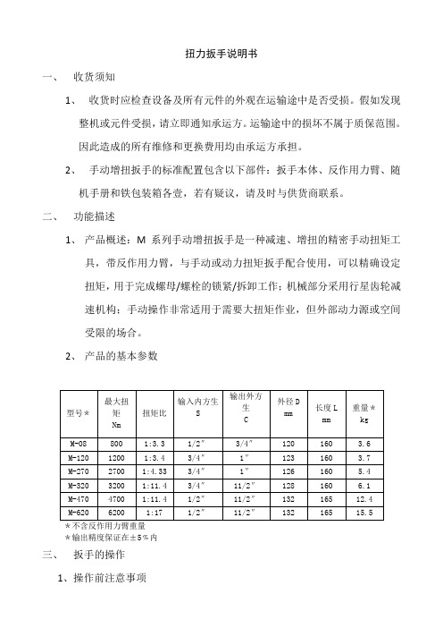
二、功能描述1、产品概述:M系列手动增扭扳手是一种减速、增扭的精密手动扭矩工具,带反作用力臂,与手动或动力扭矩扳手配合使用,可以精确设定扭矩,用于完成螺母/螺栓的锁紧/拆卸工作;机械部分采用行星齿轮减速机构;手动操作非常适用于需要大扭矩作业,但外部动力源或空间受限的场合。
2、产品的基本参数*不含反作用力臂重量*输出精度保证在±5﹪内三、扳手的操作1、操作前注意事项(1)本机器为带反作用力臂的扭矩工具,机器产生的巨大扭矩都由反作用力臂吸收,所以,在操作时都必须为反作用力臂寻找足够强度的支撑点。
(2)务必不可使用冲击式动力工具来驱动手动增扭扳手,否则,可能/不可避免会损坏传动系统,强烈建议与手动扭矩扳手配合使用,不可输入超过规定的上限扭矩。
(3)鉴于安全考虑,在机器工作时,人体任何部位都务必避开反作用力臂的工作范围,否则,将不可避免的对人身造成巨大的伤害。
(4)手动扭矩扳手是精密扭矩工具,每次使用前,务必检查防反弹棘轮装置、输出方头、反作用力臂等部件是否完好,及配套手动扭矩扳手精度;否则可能导致人身或财产损失。
四、操作方法1、锁紧螺母(1)、确认锁扭矩。
按照设备装配工艺要求/查表/计算等方法,得出锁紧扭矩。
(2)、用目标扭矩值除以手动增扭扳手的扭矩比,得出需要输入的扭矩值,并将手动扭矩扳手调至相应的扭矩值。
(3)、将反作用力臂和套筒就位,并将反作用力臂支撑在相邻的螺栓或其它支撑点上,反作用力臂支撑点必须有足够强度,足以承受反作用扭矩,反作用扭矩和输出扭矩相同。
(4)、将手动扭矩扳手的输出方头插入手动增扭扳手的输入方孔,即顺时针方向操作手动扭矩扳手,操作时,尽量使扳手在垂直于输入方身轴线的平面上运动。
电批扭力测试仪SOP
(文件名称)文件发放/使用场所 STPDQAFXBY文件发放数量/形式 1#1#1#1#11#1#1#1#1#编写/修订部门 编写/修订人 会审部门 部门负责人会审部门部门负责人批准人品保部 黄东 品保部文件编号 发行日期 2010年06月22日 版本 A 共2页,第1页1.0目的为了使检查员能够熟练的掌握技能及确保测试的准确性。
2.0适用范围适用于本公司电动扭力批和气动扭力批的扭力校正。
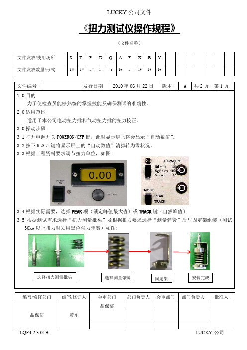
3.0操动步骤3.1打开电源开关POWERON/OFF 键,此时显示屏上将会显示“自动数值”。
3.2按下RESET 键将显示屏上的“自动数值”清掉转为零状况。
3.3根据工程资料要求调节扭力单位,如图:3.4根据实际需要,选择PEAK 项(锁定峰值最大值)或TRACK 键(自然峰值)3.5根据测试需求选择“扭力测量批头”及根据扭力要求选择“测量弹簧”后与固定架组装(测试30kg 以上扭力时须用黑色强力弹簧)如图:安装完成选择测量弹簧固定架选择扭力测量批头(文件名称)文件发放/使用场所S T P D Q A F X B Y文件发放数量/形式1#1#1#1# 1 1# 1#1# 1# 1#编写/修订部门编写/修订人会审部门部门负责人会审部门部门负责人批准人品保部黄东品保部文件编号发行日期2010年06月22日版本 A 共2页,第2页3.6将电批口与“扭力测量批”接合并按下电批电源开关,将弹簧锁到底并发出“咔、咔、咔”响后,即可松掉电批电源开关,此时显示屏上会出现实测扭力数据,如扭力数据偏大或偏小,可调电批的刻度后再次按3.6操作。
3.7当测试完毕后,将测试固定架取下放入保护槽内,然后将显示屏上的数据清零。
4.0仪器的维护和保养4.1为了节约用电,若在测量过程中较长时间不用,请将电源开关关掉。
4.2使用时应放置在平整的工作台面上,无震动。
4.3尽量远离高强度的磁场,电场及发生高频波的电器设备。
4.4时常用干净的白布对仪器的表面及显示屏进行擦拭。
凯特克液压扳手使用手册
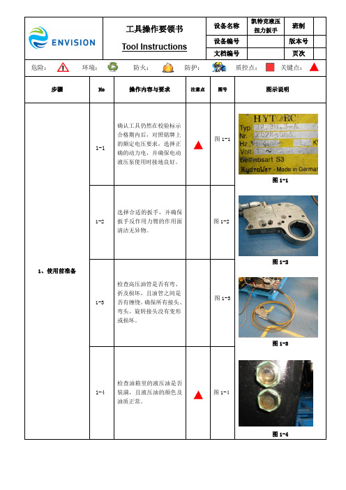
原因:油温冷却系统空气通道堵塞; 11-3
措施:清洁散热器的空气通道;
图 9-1 图 9-2 图 9-4 图 10-1 图 10-4 图 11-3
12-1 12、电动泵电控箱上的 指示灯不亮
12-2
原因:电源插座或电源线故障; 措施:检查电源线,若存在断路更 换电源线;
原因:遥控线缆存在断路; 措施:更换遥控线缆;
图 5-9
5-10
滤网需每年更换一次,马达 轴与轴承也应每年清洗及 加润滑油一次。
图 5-10
图 5-7 图 5-8 图 5-9
5-11
电机马达上带有自动温控 装置,若线圈温度超过 150℃后马达会自动停机。 转子线圈每年检查一次,避 免频繁超温导致温控装置 失灵。使用中如发现泵组油 箱温度很高,但马达仍在运 行,仍可继续使用。
松开黑色按钮,如需精确 调节压力值,可重新按下 黑色按钮进行调节,按红
4-8
色按钮则马达停止,如数 值不准确,再按第一步重 新调整。
图 4-8
图 4-7 图 4-8
所有运动部件都应每两周
5-1 应清洗一次并涂上油质的
NLGI#2 二硫化钼进行润 滑。
图 5-1
每次工作结束后应检查油 管是否存在断裂与泄漏、 所有油管接头是否有裂 5-2 纹,并定期清洗变脏的接 头,如发现接头有裂纹, 需立刻更换。
1-2
原因:电磁阀螺线管不起作用; 措施:更换电磁阀,或螺线管。
图 1-1
原因:泵站的电压太低或电流不足; 措施:选择较短的电缆线或更换为 2-1 12AWG,25A 的或更好的电线,按照 铭牌选择合适的动力电压。
2、扳手油缸不回退
原因:接头失效或松动; 2-2
措施:拧紧或更换接头。
