SD5000中文资料
船厂船东中英文名称
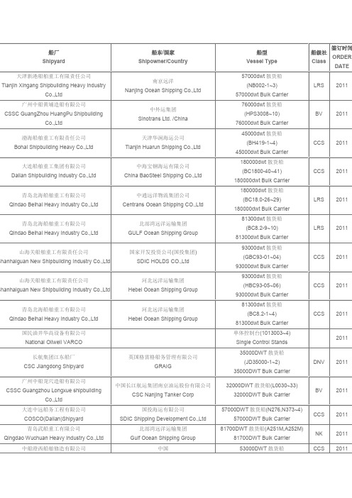
CCS CCS LRS
2011
2011 2011 2011 2011 2011 2011 2010 2010 2010 2010 2010 2010 2010
2010
2010 2010
Tianjin Xingang Shipbuilding Heavy Industry
船型 Vessel Type
57000dwt 散货船 (NB002-1~3)
57000dwt Bulk Carrier 76000dwt 散货船 (HPS3008~10)
76000dwt Bulk Carrier 45000dwt 散货船 (BH419-1~4)
45000dwt Bulk Carrier 180000dwt 散货船 (BC1800-40~41)
Transform CaCCS CCS
57000DWT 散货船(HPS3017~20) 57000DWT Bulk Carrier
CCS
57000DWT 散货船 (N301)
57000DWTBulk Carrier 57000DWT 散货船 (CIS57000/B-07~10)
大连港集团万通物流有限公司 PDA Wantong Logistics Co.,Ltd
29000DWT 多用途船 (HCY141~2)
29000DWT Multi-purpose Carrier
江苏熔盛重工集团有限公司 Jiangsu Rongsheng Shipbuilding Co.,Ltd
Fujian Jiuzhou Shipping Co.,Ltd
(NB001-1~3)
Co.,Ltd
57,000DWT Bulk Carrier
cendov变频器sd5000说明书e-02
cendov变频器sd5000说明书e-02【引言】在当今工业自动化领域,变频器作为一种调节电机转速和输出功率的设备,越来越受到企业的青睐。
CENDOV变频器SD5000以其出色的性能和便捷的操作赢得了广泛好评。
本文将详细介绍CENDOV变频器SD5000的产品特点、安装方法、操作与维护等方面的内容,帮助用户更好地理解和使用这款产品。
【产品概述】CENDOV变频器SD5000是一款高性能、高可靠性的变频器产品。
它具有以下特点:1.采用先进的控制算法,实现高精度、高速度的电机控制;2.支持多种通信接口,如RS-485、Profibus等,方便与其他设备连接;3.具备丰富的保护功能,如过载保护、过压保护、短路保护等;4.操作简便,支持远程控制和监控;5.结构紧凑,占地面积小,便于安装和维护。
【安装与接线】1.安装前,请确保准备好以下物品:CENDOV变频器SD5000、电机、电缆、工具(如螺丝刀、扳手等);2.根据电气原理图,将变频器与电机、电源、负载设备进行连接;3.确保接线正确无误,避免短路、漏电等安全隐患;4.接线完成后,进行检查,确保无误;5.安装完成后,进行电气绝缘测试,确保安全。
【操作与维护】1.操作面板:CENDOV变频器SD5000的操作面板包括电源开关、模式切换开关、频率调整旋钮等,用户可根据需求进行设置;2.维护:定期对变频器进行清洁、检查,确保内部元件无损坏,保持设备良好运行状态;3.更换部件:如发现损坏部件,应立即停机更换,确保设备安全运行。
【故障处理】1.故障现象:如电机无法启动、运行中突然停止等;2.处理方法:检查电源、电缆、电机等是否正常,如有异常,及时排除;3.如无法自行解决问题,请联系售后服务人员。
【安全防护】1.严格遵守操作规程,确保人身安全;2.操作时,请勿触摸带电部分,避免触电;3.设备运行时,请勿靠近,以免发生意外。
【参数设置与调试】1.根据实际需求,进行参数设置,如设定电机额定频率、启动方式等;2.调试过程中,密切关注电机运行状态,如发现异常,及时调整;3.确保参数设置与电机性能相匹配,以达到最佳运行效果。
DVU 5000 DTMB激励器-中文版操作手册
1
1
2
3
4.......................................................................... 4 1.1 概述 ....................................................................... 4 1.2 安全防范..................................................................... 4 1.3 注意与警告声明............................................................... 4 1.4 安全防护...............................
Acterna SDA-5000系列Stealth数字分析器的中文名字说明书
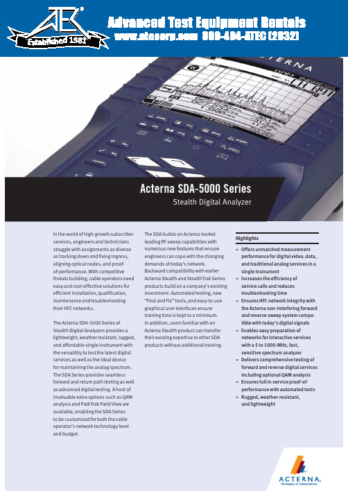
800-404-ATEC (2832) E s t a b l i s h e d1981Acterna SDA-5000 SeriesStealth Digital AnalyzerForward and reverse non-interfering Sweep enableseasy preparation of networks for interactive services 23Reverse ingress spectrum displayConstellation display with MER and pre/post FEC BERReverse Alignment mode prepares network for cable modem deploymentOne button, in-service C/N measurements on TDMA return path cable modem signals(DOCSIS, EuroDOCSIS, EuroModem) Zero span/time domain expert mode, showing the TDMA bursty return path cable modem power ramp of 3.5 msIn-service ingress spectrum showing CTB/CSO-intermodulation problems due to analog-TV channels4Time domain view of ingress in the Zero Span mode captures elusive ingress PathTrak Field View option compares headendnode spectrum with field testpoint spectrumGraphical reverse testpoint compensation5The single-channel level display shows both video and audio levels(either single or dual sound/ NICAM) and the difference between the two Digital channel average power measurements can be made using the digiCheck™featureThe Navigator user interface, common on all Acterna SDA meters6Automated tests can be scheduled to perform either 24-hour FCC compliance tests, or initiated immediately to log performance at individual nodes, amplifiers, or other testpoints. A wide range of tests can be performed auto-matically, including signal levels,C/N, hum, and depth of modulation. The operator designates which tests to perform on which channels. Because these tests are non-intrusive, it is easy to test all parameters on all channels at any time.After a test is performed, the results can be displayed on the SDA screen.A PASS/FAIL indication on a varietyof limits can be set for FCC/CENELECor other government standards,or system preferences. Data taken during any automated test, or sequence of automated tests, can be viewed immediately with a PASS/FAIL indication for each of the limits. Specific stored measurement results may be viewed on demand. Data analysis with StealthWareTest results can be printed directly to aserial printer or uploaded to a PC usingActerna StealthWare, a Microsoft®Windows®-based data managementpackage, to store and include in cus-tom reports. Stored sweep, scan, orspectrum screens can be viewed onthe PC and analyzed with marker move-ment and readout information in justthe same way as on the actual instru-ment. A sweep graph overlay functionallows comparison of multiple RFresponse variations over time. Oldsweep graphs may be downloadedback into the SDA instrument for real-time comparison.Powerful and intuitive standardizedgraphical displaysAll measurement results are presentedto the user in clear, highly informative,summary displays. The graphicspresent the information the way thetechnician wants to see the results,with no further interpretation required.For example, testpoint compensationvalues are entered at the start oftesting. Displays then calculate actuallevels automatically, minimizingfield errors.Reduced training timeWith SDA Series products, all levels ofinstruments are familiar to the tech-nician, regardless of which is learnedfirst, because the same user interfaceconventions are used across all prod-uct families. The time needed for atrainee technician to learn to use theinstrument is considerably shorterthan with alternative test equipment.This means urgent upgrade projectsmake the most efficient use of limitedresources when SDA Series productsare used.7 Limit checks can be instantly viewed afteridentifying channel of interest with a markerin Scan mode displayIn-service carrier-to-noiseTilt mode performs automatic tilt calculations between any two of nine designated carriersDepth of modulation In-service “HUM” (PAL and NTSC compatible)Detailed forward/ reverse sweep graph offers adjustable markers, scale, reference level and tilt. Users can clearly distinguish between previous and current sweep measurements for easy891011Worldwide Headquarters12410 Milestone Center Dr. Germantown, Maryland 20876-7100USAActerna is present in more than 80 countries.To find your local sales office go to: Regional SalesHeadquartersNorth America12410 Milestone Center Dr.Germantown, Maryland20876-7100USAToll Free:1866ACTERNAToll Free:186********Tel:+13013531560x2850Fax: +1301353 9216Latin AmericaAv.Eng.Luis Carlos Berrini936/8°e 9°andares04571-000 São PauloSP-BrazilTel:+551155033800Fax:+55 11 5505 1598Asia Pacific42 Clarendon StreetPO Box 141South MelbourneVictoria 3205AustraliaTel:+61 3 9690 6700Fax:+61 3 9690 6750Western EuropeArbachtalstrasse 672800 Eningen u.A.GermanyTel:+49 7121 86 2222Fax:+49 7121 86 1222Eastern Europe,Middle East & AfricaElisabethstrasse 362500 BadenAustriaTel:+43 2252 85 521 0Fax:+43 2252 80 7271st Neopalimovskiy Per.15/7 (4th floor)RF 119121 MoscowRussiaTel:+7 095 248 2508Fax:+7 095 248 4189© Copyright 2002Acterna, LLC.All rights reserved.Acterna, The Keepers ofCommunications, andits logo are trademarksof Acterna, LLC. Allother trademarks andregistered trademarksare the property of theirrespective owners. MajorActerna operations sitesare IS0 9001 registered.Note: Specifications,terms and conditionsare subject to changewithout notice.SDA-5000/DS/CAB/07-02/AE/ACT00392Acterna Advantage SM–adding value with global services and solutionsFrom basic instrument support for your field technicians to management of complex, company-wide initiatives, Acterna’s service professionals are committed to helping you maximize your return on investment. Whatever your needs– product support, system management, education services, or business planning and consulting – we offer programs that will give you the competitive edge. This is the foundation of Acterna Advantage.Acterna is the world’s largest provider of test and management solutions for optical transport, access and cable networks, and the second largest communications test company overall. Focused entirely on providing equipment, software, systems and services, Acterna helps customers develop, install, manufacture and maintain optical transport, access, cable, data/IP and wireless networks.。
2Bxxxx-xxx-3BD中文资料
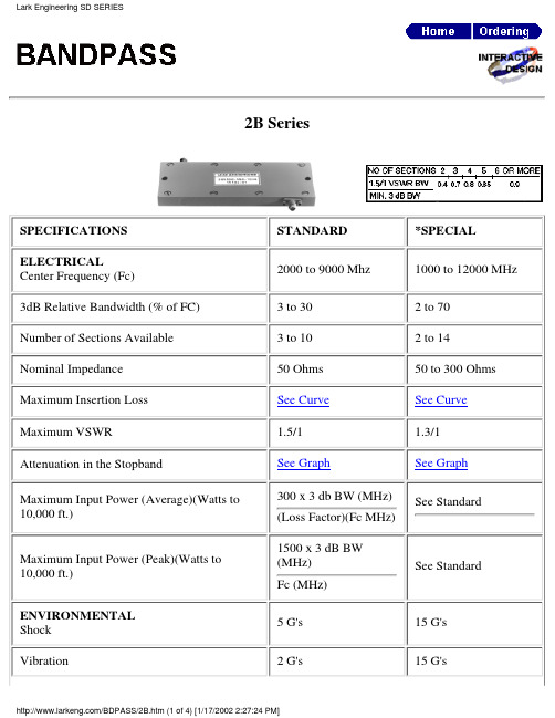
2B SeriesSPECIFICATIONS STANDARD *SPECIAL ELECTRICALCenter Frequency (Fc)2000 to 9000 Mhz 1000 to 12000 MHz 3dB Relative Bandwidth (% of FC) 3 to 30 2 to 70Number of Sections Available 3 to 10 2 to 14Nominal Impedance 50 Ohms 50 to 300 Ohms Maximum Insertion Loss See Curve See Curve Maximum VSWR 1.5/1 1.3/1Attenuation in the StopbandSee GraphSee Graph Maximum Input Power (Average)(Watts to 10,000 ft.)300 x 3 db BW (MHz)(Loss Factor)(Fc MHz)See StandardMaximum Input Power (Peak)(Watts to 10,000 ft.)1500 x 3 dB BW (MHz)Fc (MHz)See StandardENVIRONMENTAL Shock 5 G's 15 G's Vibration2 G's15 G'sHumidity90% relative100% relative Altitude Unlimited UnlimitedTemperature Range (Operating)-25 to + 50 degreescelsius-54 to + 100 degreescelsiusTemperature Range (Non-Operating)-54 to + 70 degreescelsius-62 to +150 degreescelsiusMECHANICALApproximate Weight in oz.1.7 x L x W 1.0 x L x WMounting Provisions See below Consult FactoryINSERTION LOSS:The Maximum Insertion Loss atcenter frequency is equal to :LF x (N + 0.5) / % 3 dB BW + 0.1Where:LF= Loss Factor, N= Number ofSections% 3dB BW:3dB BW (MHz) x 100divided byCenter Frequency (MHz)Example:A 5 section 2B with a centerfrequencey of 5000 MHz and a 3dBBW of 500 MHz would have,.08 x 5.5 /10 = 4.4 /10 = 0.44 + 0.1= 0.5 dbMECHANICAL SPECIFICATIONSL Dimension = 1.5 inch = (0.5 x No. of Sections) Approx.W Dimension = 2950 / Fc (MHz) + 0.6 inch Approx.Connectors Available On 2B Series:Lark Code Type C DIM.Inches & MM Lark Code Type C DIM.Inches & MM A SMA JACK .375 & 9.5*G N JACK .736 & 18.7BSMA PLUG.507 & 12.9*HN PLUG.819 & 20.8Lark Engineering SD SERIES元器件交易网*C TNC JACK .750 & 19.1S SPECIAL*D TNC PLUG.844 & 21.4* Not recommended for use with this SeriesThe size shown is a standard used by Lark to facilitate a low cost, easily reproducible unit. Should you require another size, please submit all of your requirements-both electrical and mechanical. This will enable Lark Engineering to quote theoptimum design for your application.Lark Engineering SD SERIES元器件交易网STOPBAND SPECIFICATIONSThe graphs on the following pages define the normal specification limits on attenuation Lark bandpass filter series 2B, 3B, and 4B. The minimum level of attenuation in dB is shown as a "number of 3dB bandwidths from centerfrequency".Since the frequency characteristics vary for differing bandwidths, it is necessary to establish specifications for each bandwidth of filter. The different graphs represent various 3dB percentage bandwidths. Intermediate values should be interpolated. The 3dB percentage bandwidth is defined as follows:3dB Bandwidth (MHz) x 100divided byCenter Frequency (MHz)The exact relationship is as follows:1. 3dB Bandwidths From Center Frequency= Rejection Frequency (Mhz) -Center Frequency (Mhz) divided by 3dB Bandwidth (Mhz)Example:Given:2. Center Frequency = 5000 MHz Minimum 3dB Bandwidth = 500 MHzNumber of Sections = 5Find: Minimum attenuation levels at 4250 MHz and 5800 MHz.3dB BW's from Fc = 4250 - 5000 / 500 = - 1.5and 5800 - 5000 / 500 = + 1.6The answer can be read directly from the 10% graph. Using the 5 section curve at the point -1.5 (4250 MHz) we find the minimum level of attenuation is 40dB.At +1.6 (5800 MHz) the minimum level of attenuation is 50dB.For special requirements, please contact our Application EngineeringDepartment.STOPSP3.HTM元器件交易网STOPBAND SPECIFICATIONSSTOPBAND SPECIFICATIONSSTOPSP3.HTM元器件交易网STOPBAND SPECIFICATIONS。
SD卡中文资料

SD卡中文资料特性:◎容量:32MB/64MB/128MB/256MB/512MB/1GByte ◎兼容规范版本1.01 ◎卡上错误校正◎支持CPRM ◎两个可选的通信协议:SD 模式和 SPI 模式◎可变时钟频率 0-25MHz ◎通信电压范围:2.0-3.6V 工作电压范围:2.0-3.6V ◎低电压消耗:自动断电及自动睡醒,智能电源管理◎无需额外编程电压◎卡片带电插拔保护◎正向兼容MMC 卡◎高速串行接口带随即存取---支持双通道闪存交叉存取---快写技术:一个低成本的方案,能够超高速闪存访问和高可靠数据存储---最大读写速率:10Mbyte/s ◎最大10 个堆叠的卡(20MHz,Vcc=2.7-3.6V) ◎数据寿命:10 万次编程/擦除◎CE 和 FCC 认证◎PIP 封装技术◎尺寸:24mm 宽×32mm 长×1.44mm 厚说明:本 SD 卡高度集成闪存,具备串行和随机存取能力。
可以通过专用优化速度的串行接口访问,数据传输可靠。
接口允许几个卡垛叠,通过他们的外部连接。
接口完全符合最新的消费者标准,叫做SD 卡系统标准,由 SD 卡系统规范定义。
SD 卡系统是一个新的大容量存储系统,基于半导体技术的变革。
它的出现,提供了一个便宜的、结实的卡片式的存储媒介,为了消费多媒体应用。
SD 卡可以设计出便宜的播放器和驱动器而没有可移动的部分。
一个低耗电和广供电电压的可以满足移动电话、电池应用比如音乐播放器、个人管理器、掌上电脑、电子书、电子百科全书、电子词典等等。
使用非常有效的数据压缩比如 MPEG,SD 卡可以提供足够的容量来应付多媒体数据。
框图:SD 卡上所有单元由内部时钟发生器提供时钟。
接口驱动单元同步外部时钟的 DAT 和 CMD 信号到内部所用时钟。
本卡由 6 线SD 卡接口控制,包括:CMD,CLK,DAT0-DAT3。
在多 SD 卡垛叠中为了标识SD 卡,一个卡标识寄存器(CID)和一个相应地址寄存器(RCA)预先准备好。
SD中文手册

一概述1. SD总线模式下CLK:时钟信号CMD:双向命令和响应信号DAT0-3:双向数据信号VDD,VSS:电源和地信号SD模式下允许有一个主机, 多个从机(即多个卡), 主机可以给从机分别地址. 主机发命令有些命令是发送给指定的从机,有些命令可以以广播形式发送.SD模式下可以选择总线宽度, 即选用几根DAT信号线, 可以在主机初始化后设置.2. SD总线协议SD模式下的命令和数据流都有一个开始位和结束位.>命令: 是在CMD上传输的用于启动一个操作的比特流. 由主机发往从机, 可以是点对点也可以是广播的.>响应: 是在CMD上传输的用于之前命令回答的比特流. 由从机发往主机.>数据: 是在DAT上传输的比特流, 双向传输.无响应模式无数据模式多块读操作模式多块写操作模式命令格式响应格式数据格式SD卡上电后会自动初始化,通过给卡发送CMD0也可以复位卡.二.SD卡命令描述.1.广播命令:给所有卡都发送, 某些命令需要响应.2.点对点命令给指定地址的卡发送, 需要响应.SD卡系统有两种工作模式:1.卡识别模式.主机上电复位后即处于此模式,它会在总线上等待卡. 卡复位后也处于此模式, 直到SEND_RCA(CMD3)命令到来.2.数据传输模式.卡收到SEND_RCA(CMD3)命令后即进入此模式. 主机识别到卡后也进入此模式.卡状态和工作模式对照表1.卡识别模式.此模式下主机复位总线所有的卡, 验证工作电压, 询问卡的地址. 这个模式下所有数据的传输都是只通过CMD线来完成.1)卡的复位.当卡上电或收到GO_IDLE_STATE (CMD0)命令后, 卡即进入Idle State状态. 此时卡将其RCA设为0, 相关寄存器设为传输稳定的最优模式.2)工作电压验证每个卡的最高和最低工作电压存储在OCR. 只有当电压比配时, CID和CSD的数据才能正常传输给主机.SD_SEND_OP_COND (ACMD41)命令用来判断卡的工作电压是否符合, 如果不符合的话, 卡应该放弃总线操作, 进入Inactive State状态. 在发送SD_SEND_OP_COND (ACMD41)命令前记得要首先发送APP_CMD (CMD55).卡的状态变换图.ACMD41命令响应中的BUSY位也用于卡表示其还没准备好, 主机此时应重发ACMD41命令,直到卡准备好.主机在这个阶段的ACMD41中不允许改变工作电压, 如果确实想改变的话, 应该先发送CMD0, 然后再发送改变后的ACMD41.GO_INACTIVE_STATE (CMD15)命令用于使指定地址的卡进入Inactive State模式.3)卡识别过程.ALL_SEND_CID (CMD2)命令用于获取卡的CID信息, 如果卡处于Ready State, 它就会在CMD线上传送它的CID信息, 然后进入Identification State模式. 紧接着发送CMD3 (SEND_RELATIVE_ADDR)命令, 用于设置卡新的地址. 卡收到新的地址后进入Stand-by State 模式.2.数据传输模式.数据传输模式下卡的状态转变图进入数据传输模式后, 主机先不停的发送SEND_CSD (CMD9)命令获取卡的CSD信息. SET_DSR (CMD4)用于设置卡的DSR寄存器, 包括数据总线宽度, 总线上卡的数目, 总线频率, 当设置成功后, 卡的工作频率也随之改变. 此步操作是可选的.CMD7命令用于使指定地址的卡进入传输模式, 任何指定时刻只能有一个卡处于传输模式.传输模式下所有的数据传输都是点对点的, 并且所有有地址的命令都需要有响应..所有读命令都可以由CMD12命令停止,之后卡进入Transfer State. 读命令包括单块读(CMD17), 多块读(CMD18), 发送写保护(CMD30), 发送scr(ACMD51)和读模式一般命令(CMD56)..所有写命令都可以由CMD12命令停止. 写命令包括单块读(CMD24), 多块读(CMD25), 写CID(CMD26), 写CSD(CMD27),锁和解锁命令(CMD42)和写模式一般命令(CMD56)..当写命令传输完成后, 卡进入Programming State(传输成功)或Transfer State(传输失败).如果一个卡写操作被停止,但其前面数据的CRC和块长度正确, 数据还是会被写入..卡要提供写缓冲, 如果写缓冲已满并且卡处于Programming State, DAT0保持低BUSY. .写CID,CSD, 写保护, 擦除命令没有缓冲, 当这些命令没完时, 不应发送其他的数据传输命令..参数设置命令在卡被编程时是不允许发送的, 这些命令包括设置块长度(CMD16), 擦除块起始(CMD32)和擦除块结束(CMD33)..当卡正编程时读命令是禁止的..用CMD7使另一个卡进入Transfer State不会终止当前卡的编程和擦除, 当前卡会进入Disconnect State并且释放DAT线.. Disconnect State模式的卡可通过CMD7重新被选中,此时卡进入Programming State 并且使能busy信号.. CMD0或CMD15会终止卡的编程操作, 造成数据混乱, 此操作应禁止.1)总线宽度选择命令ACMD6命令用于选择总线宽度, 此命令只有在Transfer State有效. 应在CMD7命令后使用.2)块读命令块是数据传输的最小单位, 在CSD (READ_BL_LEN)中定义, SD卡为固定的512B.每个块传输的后面都跟着一个CRC校验. CMD17(READ_SINGLE_BLOCK)用于传输单个块,传输完之后,卡进入Transfer State. CMD18 (READ_MULTIPLE_BLOCK)用于多个块的传输,直到收到一个CMD12命令.3)块写命令与块读命令类似, 每个块传输的后面都跟着一个CRC校验.卡写数据时会进行CRC校验.多块写比重复的单块写更能提高效率.如果CSD中的WRITE_BLK_MISALIGN没设置, 并且发送的数据不是块对齐的, 卡会设置状态寄存器中的ADDRESS_ERROR位,并且进入Receive-data-State状态等待停止命令.此时写操作也会停止, 并且卡会设置其的WP_VIOLATION位.如果写缓冲满的话, 卡会停止接受WRITE_BLOCK命令. 此时主机应发送SEND_STATUS (CMD13)命令, 卡返回数据的READY_FOR_DATA位标志卡是否准备好接受新的数据.在多块写操作中通过事先发送ACMD23命令可提高写速度. ACMD23用于定义接下来要写数据的块的数目. 每次多块写操作后, 这个值又被设为默认的1.ACMD22会使卡返回写成功的块数目.4)擦除命令擦除命令的顺序是: ERASE_WR_BLK_START(CMD32),ERASE_WR_BLK_END(CMD33)and ERASE (CMD38).如果(CMD38或(CMD32, 33)接收到出错信息, 卡会设置状态寄存器中的ERASE_SEQ_ERROR 位并且重新等待新的命令时序.如果接收到时序错误命令, 卡会设置其ERASE_RESET位并且重新等待新的命令时序.5)写保护管理三种机制:-.写保护物理开关-.卡内部写保护通过设置CSD中的WP_GRP_ENABLE位和WP_GRP_SIZE位, SET_WRITE_PROT和CLR_WRITE_PROT命令用来设置和清除保护机制.-. 密码保护.三. 时钟控制如果主机要发送1K的数据, 但是主机缓冲区只有512B, 那么主机可以在发送完前512B 后, 可以先停止时钟, 然后把后512B填充入缓冲区, 再启动时钟, 这样卡并不会检测要两次发送之间的间隔, 认为其是一次完整的数据发送过程.四 CRC校验1.CRC7CRC7用于所有的命令, 除R3以外的响应, 以及CID和CSD寄存器.2.CRC16CRC16用于数据块的校验五. 错误类型.1. CRC错误和命令非法错误命令的CRC校验出错, 卡设置其状态寄存器的COM_CRC_ERROR位.非法命令错误, 卡设置其状态寄存器的ILLEGAL_COMMAND位.非法命令包括:不支持的命令,未定义的命令以及当前状态不支持的命令.2. 读,写和擦除超时.卡应该在指定的时间内完成一个命令或返回移动的错误信息. 如果在指定的超时时间内主机收不到响应, 应认为卡停止工作, 应重新复位卡.六命令1. 命令类型:- bc不需要响应的广播命令.- bcr需要响应的广播命令. 每个卡都会独立的接收命令和发送响应.- ac点对点命令, DAT线上没数据- adtc点对点命令, DAT线上有数据所有命令均遵守上图中的格式, 总共48位. 首先是1个起始位0, 接着是1个方向位(主机发送位1), 6个命令位( 0-63 ), 32位参数(有些命令需要), CRC7位校验, 1个停止位.2.卡命令根据不同的类型分成了不同的Class, 见下表,其中Class0,2,4,5,8是每个卡都必须支持的命令, 不同的卡所支持的命令保存在CSD中.3.命令详细描述1)基本命令Class02)读命令Class23)写命令Class43)擦除命令Class54)应用特定命令Class8下表中的所有命令使用前都应先跟一个APP_CMD(CMD55)命令七. 卡状态转换表八. 应答.所有的应答都是通过CMD发送,不同的应答长度可能不同.总共有四种类型的应答.1. R1: 长度位48位.注意每个块传输完成后有一个BUSY位.2.R1b:与R1类似, 只是将BUSY位加入响应中.3.R2(CID CSD寄存器) : 长度为136位, CID为CMD2和CMD10的应答, CSD为CMD9的应答.4.R3(OCR寄存器):长度位48位. 作为ACMD41的应答.5.R6(RCA地址应答):长度为48位九. 卡的状态SD卡支持两种状态:-卡状态:与MMC卡兼容.-SD卡状态:扩充到了512位.1.卡状态:R1应答包含一个32位的卡状态.见下表.其中Type中的含义为:E:错误位. S:状态位. R:根据命令在响应中设置.X:根据在命令执行期间设置, 必须再次读此位才能获得命令执行后的情况.Clear Condition:A: 与卡的当前状态有关B: 总是与命令有关,无效的命令会清除此位.C: 通过读此位来清除下表指明了哪些命令可能使哪些位产生变化2.SD卡状态:这些位通过DAT线传输, 并伴有CRC16校验. 其是作为ACMD13的应答.十. 卡存储器形式.-块:块是基本读写命令的单位,它可以是固定的或可变的. 关于块的大小以及其是否可变性存储在CSD中.-扇区:扇区是擦除命令的单位, 它是固定的值,保存在CSD中.十一. 时序图时序图中字母含义:1.命令和应答1)卡识别和卡工作电压确认模式:CMD2,ACMD412)地址分配模式:CMD33)数据传输模式:4)命令结束->下一个命令:5)两个命令直接1)单块读:CMD172)多块读:读过程时序.停止命令时序3.数据写1)单块写:注意Busy信号.2)多块写:多块写命令时序停止命令时序卡主动停止时的时序十二.寄存器.SD卡有六个寄存器OCR, CID, CSD, RCA, DSR and SCR. 其中前四个保存卡的特定信息, 后两个用来对卡进行配置.1.OCR寄存器:保存有卡支持的工作电压, 支持的话相应的位置1,否则为0.2.CID:保存有卡的身份信息.3.CSD保存有如何访问卡的信息.TAAC定义了数据访问的异步时间部分. NSAC为数据访问最坏需要的异步时间.TRAN_SPEED定义了单条DAT线上的最快速度:CCC:SD卡支持的命令集READ_BL_LEN:最大读块长度. WRITE_BL_LEN等于READ_BL_LENDSR_IMP: DSR寄存器是否允许配置, 1为允许,0为不允许.FILE_FORMAT: SD卡上的文件格式.4.RCA保存有卡的地址信息.5.DSR用于配置卡, 默认值为0x4046.SCR寄存器也保存有卡的特定信息.SD_BUS_WIDTHS指明卡支持的传输类型.第二部分 S3C2410 SD卡控制器一 SDI操作1.CPU寄存器设置过程.1)正确设置SDICON寄存器.2)正确设置SDIPRE寄存器.3)等待74个时钟信号初始卡.2.CMD命令发送过程.1)向SDICARG寄存器中写入发送的参数.2)确定命令类型并且通过设置SDICCON[8]来启动命令.3)确定命令是否发送完成. 没应答的话看SDICSTA[11], 有应答的话看SDICSTA[9].4)清除SDICSTA中的相应位.3.数据传输过程.1)向SDITIMER中写入超时值.2)向SDIBSIZE中写入块大小的值.3)设置块模式,总线宽度等, 通过SDIDCON启动传输.4)通过SDIFSTA检查TxFIFO是否可用, 再通过SDIDAT写入发送数据.5)通过SDIFSTA检查RxFIFO是否可用, 再通过SDIDAT读入接收数据.6)通过检查SDIDSTA[4]确定传输过程已完成.7)清除SDIDSTA中的相应位.4. SDIO有两种工作模式,中断和读等待模式.二. SDI寄存器.1.SDICON:SDI控制寄存器字节序类型:Type A: D[7:0] D[15:8] D[23:16] D[31:24]Type B: D[31:24] D[23:16] D[15:8] D[7:0]2.SDIPRE:波特率预分频寄存器.4. SDICCON:SDI命令控制寄存器.5. SDICSTA:SDI命令状态寄存器.6.SDIRSP0-SDIRSP3:命令响应寄存器8. SDIBSIZE:SDI块大小寄存器.9. SDIDCON:SDI数据控制寄存器10. SDIDCNT:SDI数据维持寄存器.12. SDIFSTA:SDI FIFO状态寄存器13. SDIDAT:SDI数据寄存器。
SD5000N中文资料

Siliconix S-51850—Rev. G, 14-Apr-97
1
SD5000/5400 Series
Absolute Maximum Ratings (TA = 25_C Unless Otherwise Noted)
Benefits
D High-Speed System Performance D Low Insertion Loss at High Frequencies D Low Transfer Signal Loss D Simple Driver Requirement D Single Supply Operation
Specificationsa
Limits
SD5000 SD5400 SD5001 SD5401
Parameter Switching
Turn-On Turn On Time Turn-Off Turn Off Time
Symbolb
td(on) tr td(off) tf
Test Conditionsb
rDS(on)
VSB = 0 V ID = 1 mA
SD5400 Series VGS = 5 V VGS = 10 V VGS = 15 V VGS = 20 V
Resistance Match
DrDS(on)
VGS = 5 V
5
5
Dynamic
Forward Transconductance gf fs C(GS+GD+GB) C(GD+DB) C(GS+SB) Crss f= 3 kHz VDS = 10 V f = 1 MHz VGS = VBS = –15 V SD5000 Series VDS = 10 V VSB = 0 V ID = 20 mA f = 1 kHz SD5000 Series SD5400 Series 12 11 2.5 2.0 3.7 0.2 –107 10 9 3.5 3 5 0.5 10 mS 9 3.5 3 5 0.5 dB pF
速达5000系列培训手册帮助文档使用说明
速达5000系列培训手册速达软件客户技术部2012.05目录1.速达5000系列市场定位--------------------------------------------------4 2.产品特点----------------------------------------------------------------4 3.产品价格----------------------------------------------------------------5 4.功能对比---------------------------------------------------------------5 5.ERP基础知识5.1ERP发展史5.2生产管理概念6.软件基本知识-----------------------------------------------------------6 6.1存货计价方法---------------------------------------------66.2固定资产折旧方法---------------------------------------------------6 6.4产品成本构成6.5成本费用分摊方法6、6财务分析常用指标7.流程简介----------------------------------------------------------------7 8.容详解----------------------------------------------------------------8 8.1新建帐套---------------------------------------------------------8 8.2初始化要点---------------------------------------------------------8 8.3采购系统-----------------------------------------------------------9 8.4仓库系统----------------------------------------------------------13 8.5销售系统----------------------------------------------------------17 8.生产系统-----------------------------------------------------------23 8.7应收应付----------------------------------------------------------23 8.8现金银行----------------------------------------------------------25 8.9企业信息----------------------------------------------------------29 8.10审核中心---------------------------------------------------------34 8.11开票管理---------------------------------------------------------35 统计分析-------------------------------------------------------------38 进销存月未处理-------------------------------------------------------40 帐务系统-------------------------------------------------------------41 单据模板与打印样式的设计---------------------------------------------44 日常维护-------------------------------------------------46用户自定义报表-------------------------------------------------50升级---------------------------------------------------531、速达5000系列市场定位速达5000系列广泛适用于中型工业加工企业及商品流通企业。
SD530中文资料

CJ
550
Storage Operating Temperature Range
TJ, TSTG
-55 to + 125
Note : 1. Mounted on PC Board with 14mm2(0.013mm thick) copper pad areas. 2. Measured at 1 MHz and applied reverse voltage of 4.0 volts.
FIG. 3 - TYPICAL JUNCTION CAPACITANCE 10000
INSTANTANEOUS FORWARD CURRENT, (A)
FIG. 2 - TYPICAL INSTANTANEOUS FORWARD
CHARACTERISTICS
SD550~SD560
50
SD520~SD540
.024(0.6) .018(0.4)
.032 (0.8)
Max
.181 (4.6)
Typ
.095(2.4) .087(2.2)
no suffix
3
2
"Y" suffixed
1 3
2
Dimensions in inches and (millimeters)
Maximum Recurrent Peak Reverse Voltage
SYMBOL VRRM VRMS VDC
SD520 20 14 20
SD530 30 21 30
SD540 40 28 40
SD550 50 35 50
SD560 60 42 60
SD580 80 56 80
SD5100 100 70 100
SP5000 硬件手册说明书

SP5000系列 硬件手册SP5000-MM01-CS-PDF_K本文档中提供的信息包含有关此处所涉及产品之性能的一般说明和/或技术特性。
本文档并非用于 (也不代替) 确定这些产品对于特定用户应用场合的适用性或可靠性。
任何此类用户或设备集成商都有责任就相关特定应用场合或使用方面对产品执行适当且完整的风险分析、评估和测试。
Schneider Electric 或其任何附属机构或子公司 (以下简称Schneider Electric) 对于误用此处包含的信息而产生的后果概不负责。
如果您有关于改进或更正此出版物的任何建议、或者从中发现错误、请通知我们。
本手册可用于法律所界定的个人以及非商业用途。
在未获得施耐德电气书面授权的情况下,不得翻印传播本手册全部或部分相关内容、亦不可建立任何有关本手册或其内容的超文本链接。
施耐德电气不对个人和非商业机构进行非独占许可以外的授权或许可。
请遵照本手册或其内容原义并自负风险。
与此有关的所有其他权利均由施耐德电气保留。
在安装和使用本产品时、必须遵守国家、地区和当地的所有相关的安全法规。
出于安全方面的考虑和为了帮助确保符合归档的系统数据、只允许制造商对各个组件进行维修。
当设备用于具有技术安全要求的应用场合时、必须遵守有关的使用说明。
未能使用施耐德电气软件或认可的软件配合我们的硬件,则可能导致人身伤害、设备损坏或不正确的运行结果。
不遵守此信息可能导致人身伤害或设备损坏。
Copyright © 2019 Schneider Electric Japan Holdings Ltd。
保留所有权利。
2SP5000 系列 硬件手册目录安全信息. . . . . . . . . . . . . . . . . . . . . . . . . . . . . . . . . . . . . 7关于本书. . . . . . . . . . . . . . . . . . . . . . . . . . . . . . . . . . . . . 9第1章概述. . . . . . . . . . . . . . . . . . . . . . . . . . . . . . . . . . . . . . . . . 13型号配置 . . . . . . . . . . . . . . . . . . . . . . . . . . . . . . . . . . . . . . . . . . . . . . . 14型号. . . . . . . . . . . . . . . . . . . . . . . . . . . . . . . . . . . . . . . . . . . . . . . . . . . 15装箱物品 . . . . . . . . . . . . . . . . . . . . . . . . . . . . . . . . . . . . . . . . . . . . . . . 16认证与标准. . . . . . . . . . . . . . . . . . . . . . . . . . . . . . . . . . . . . . . . . . . . . . 18联邦通讯委员会射频干扰声明 - 适用于美国. . . . . . . . . . . . . . . . . . . . . 20危险位置安装 - 适用于美国和加拿大. . . . . . . . . . . . . . . . . . . . . . . . . . 21符合欧盟 (CE) 标准 . . . . . . . . . . . . . . . . . . . . . . . . . . . . . . . . . . . . . . . 23KC 标志. . . . . . . . . . . . . . . . . . . . . . . . . . . . . . . . . . . . . . . . . . . . . . . . 24无线 LAN 信息. . . . . . . . . . . . . . . . . . . . . . . . . . . . . . . . . . . . . . . . . . . 25第2章设备连接. . . . . . . . . . . . . . . . . . . . . . . . . . . . . . . . . . . . . 29系统设计 . . . . . . . . . . . . . . . . . . . . . . . . . . . . . . . . . . . . . . . . . . . . . . . 30附件. . . . . . . . . . . . . . . . . . . . . . . . . . . . . . . . . . . . . . . . . . . . . . . . . . . 32第3章部品标识及其功能. . . . . . . . . . . . . . . . . . . . . . . . . . . . . . 373.1主机模块 . . . . . . . . . . . . . . . . . . . . . . . . . . . . . . . . . . . . . . . . . . . . . . . 38标准主机模块. . . . . . . . . . . . . . . . . . . . . . . . . . . . . . . . . . . . . . . . . . . . 39增强型主机模块. . . . . . . . . . . . . . . . . . . . . . . . . . . . . . . . . . . . . . . . . . 41开放型主机模块. . . . . . . . . . . . . . . . . . . . . . . . . . . . . . . . . . . . . . . . . . 43LED 指示. . . . . . . . . . . . . . . . . . . . . . . . . . . . . . . . . . . . . . . . . . . . . . . 453.2显示模块 . . . . . . . . . . . . . . . . . . . . . . . . . . . . . . . . . . . . . . . . . . . . . . . 46精良显示 . . . . . . . . . . . . . . . . . . . . . . . . . . . . . . . . . . . . . . . . . . . . . . . 47高级显示模块. . . . . . . . . . . . . . . . . . . . . . . . . . . . . . . . . . . . . . . . . . . . 51LED 指示. . . . . . . . . . . . . . . . . . . . . . . . . . . . . . . . . . . . . . . . . . . . . . . 55第4章规格. . . . . . . . . . . . . . . . . . . . . . . . . . . . . . . . . . . . . . . . . 574.1一般规格 . . . . . . . . . . . . . . . . . . . . . . . . . . . . . . . . . . . . . . . . . . . . . . . 58规格电气 . . . . . . . . . . . . . . . . . . . . . . . . . . . . . . . . . . . . . . . . . . . . . . . 59规格环境 . . . . . . . . . . . . . . . . . . . . . . . . . . . . . . . . . . . . . . . . . . . . . . . 61结构规格 . . . . . . . . . . . . . . . . . . . . . . . . . . . . . . . . . . . . . . . . . . . . . . . 624.2功能规格 . . . . . . . . . . . . . . . . . . . . . . . . . . . . . . . . . . . . . . . . . . . . . . . 65显示规格 . . . . . . . . . . . . . . . . . . . . . . . . . . . . . . . . . . . . . . . . . . . . . . . 66存储器 . . . . . . . . . . . . . . . . . . . . . . . . . . . . . . . . . . . . . . . . . . . . . . . . . 67时钟. . . . . . . . . . . . . . . . . . . . . . . . . . . . . . . . . . . . . . . . . . . . . . . . . . . 68触摸屏 . . . . . . . . . . . . . . . . . . . . . . . . . . . . . . . . . . . . . . . . . . . . . . . . . 694.3接口规格 . . . . . . . . . . . . . . . . . . . . . . . . . . . . . . . . . . . . . . . . . . . . . . . 70接口规格 . . . . . . . . . . . . . . . . . . . . . . . . . . . . . . . . . . . . . . . . . . . . . . . 71接口连接 . . . . . . . . . . . . . . . . . . . . . . . . . . . . . . . . . . . . . . . . . . . . . . . 74用于 COM1/COM2 的串行接口 (RS-232C 和 RS-422/RS-485). . . . . . 77辅助输出/扬声器输出接口 (AUX). . . . . . . . . . . . . . . . . . . . . . . . . . . . . 80DVI-D 输出接口. . . . . . . . . . . . . . . . . . . . . . . . . . . . . . . . . . . . . . . . . . 813第5章尺寸 . . . . . . . . . . . . . . . . . . . . . . . . . . . . . . . . . . . . . . . . .835.1标准主机模块 . . . . . . . . . . . . . . . . . . . . . . . . . . . . . . . . . . . . . . . . . . . .84SP-5B00 . . . . . . . . . . . . . . . . . . . . . . . . . . . . . . . . . . . . . . . . . . . . . . .845.2增强型主机模块 . . . . . . . . . . . . . . . . . . . . . . . . . . . . . . . . . . . . . . . . . .85SP-5B10 . . . . . . . . . . . . . . . . . . . . . . . . . . . . . . . . . . . . . . . . . . . . . . .855.3开放型主机模块 . . . . . . . . . . . . . . . . . . . . . . . . . . . . . . . . . . . . . . . . . .86SP-5B40/SP-5B41. . . . . . . . . . . . . . . . . . . . . . . . . . . . . . . . . . . . . . . .865.4精良显示模块 . . . . . . . . . . . . . . . . . . . . . . . . . . . . . . . . . . . . . . . . . . . .87SP-5500TP. . . . . . . . . . . . . . . . . . . . . . . . . . . . . . . . . . . . . . . . . . . . . .88SP-5600TP/SP-5660TP. . . . . . . . . . . . . . . . . . . . . . . . . . . . . . . . . . . .89SP-5700TP. . . . . . . . . . . . . . . . . . . . . . . . . . . . . . . . . . . . . . . . . . . . . .90SP-5700WC. . . . . . . . . . . . . . . . . . . . . . . . . . . . . . . . . . . . . . . . . . . . .91SP-5800WC. . . . . . . . . . . . . . . . . . . . . . . . . . . . . . . . . . . . . . . . . . . . .925.5高级显示模块 . . . . . . . . . . . . . . . . . . . . . . . . . . . . . . . . . . . . . . . . . . . .93SP-5400WA. . . . . . . . . . . . . . . . . . . . . . . . . . . . . . . . . . . . . . . . . . . . .94SP-5500WA. . . . . . . . . . . . . . . . . . . . . . . . . . . . . . . . . . . . . . . . . . . . .95SP-5600WA. . . . . . . . . . . . . . . . . . . . . . . . . . . . . . . . . . . . . . . . . . . . .96SP-5600TA. . . . . . . . . . . . . . . . . . . . . . . . . . . . . . . . . . . . . . . . . . . . . .975.6主机模块和显示模块 - 组合尺寸. . . . . . . . . . . . . . . . . . . . . . . . . . . . . .98SP-5500TP 带主机模块 . . . . . . . . . . . . . . . . . . . . . . . . . . . . . . . . . . . .99SP-5600TP/SP-5660TP 带主机模块 . . . . . . . . . . . . . . . . . . . . . . . . . .101SP-5700TP 带主机模块 . . . . . . . . . . . . . . . . . . . . . . . . . . . . . . . . . . . .103SP-5700WC 带主机模块 . . . . . . . . . . . . . . . . . . . . . . . . . . . . . . . . . . .105SP-5800WC 带主机模块 . . . . . . . . . . . . . . . . . . . . . . . . . . . . . . . . . . .107SP-5400WA 带主机模块 . . . . . . . . . . . . . . . . . . . . . . . . . . . . . . . . . . .109SP-5500WA 带主机模块 . . . . . . . . . . . . . . . . . . . . . . . . . . . . . . . . . . .111SP-5600WA 带主机模块 . . . . . . . . . . . . . . . . . . . . . . . . . . . . . . . . . . .113SP-5600TA 带主机模块 . . . . . . . . . . . . . . . . . . . . . . . . . . . . . . . . . . . .115第6章安装和接线. . . . . . . . . . . . . . . . . . . . . . . . . . . . . . . . . . . .1176.1安装 . . . . . . . . . . . . . . . . . . . . . . . . . . . . . . . . . . . . . . . . . . . . . . . . . . .118安装步骤. . . . . . . . . . . . . . . . . . . . . . . . . . . . . . . . . . . . . . . . . . . . . . . .1186.2接线规则. . . . . . . . . . . . . . . . . . . . . . . . . . . . . . . . . . . . . . . . . . . . . . . .130连接 DC 电源线 . . . . . . . . . . . . . . . . . . . . . . . . . . . . . . . . . . . . . . . . . .131连接电源. . . . . . . . . . . . . . . . . . . . . . . . . . . . . . . . . . . . . . . . . . . . . . . .133接地 . . . . . . . . . . . . . . . . . . . . . . . . . . . . . . . . . . . . . . . . . . . . . . . . . . .1356.3USB 电缆紧固夹. . . . . . . . . . . . . . . . . . . . . . . . . . . . . . . . . . . . . . . . . .136A 型 USB 电缆夹 (1 个端口). . . . . . . . . . . . . . . . . . . . . . . . . . . . . . . . .137USB 电缆夹 mini-B (1 个端口) . . . . . . . . . . . . . . . . . . . . . . . . . . . . . . .1396.4AUX 接头 . . . . . . . . . . . . . . . . . . . . . . . . . . . . . . . . . . . . . . . . . . . . . . .141简介 . . . . . . . . . . . . . . . . . . . . . . . . . . . . . . . . . . . . . . . . . . . . . . . . . . .1416.5SD 卡插入/拔出 . . . . . . . . . . . . . . . . . . . . . . . . . . . . . . . . . . . . . . . . . .142简介 . . . . . . . . . . . . . . . . . . . . . . . . . . . . . . . . . . . . . . . . . . . . . . . . . . .143SD卡插入. . . . . . . . . . . . . . . . . . . . . . . . . . . . . . . . . . . . . . . . . . . . . . .144SD卡移除. . . . . . . . . . . . . . . . . . . . . . . . . . . . . . . . . . . . . . . . . . . . . . .145SD 卡备份 . . . . . . . . . . . . . . . . . . . . . . . . . . . . . . . . . . . . . . . . . . . . . .146 4SP5000 系列 硬件手册6.6CFast 卡 插入/移除 . . . . . . . . . . . . . . . . . . . . . . . . . . . . . . . . . . . . . . . 147简介. . . . . . . . . . . . . . . . . . . . . . . . . . . . . . . . . . . . . . . . . . . . . . . . . . . 148CFast卡插入 . . . . . . . . . . . . . . . . . . . . . . . . . . . . . . . . . . . . . . . . . . . . 149CFast卡移除 . . . . . . . . . . . . . . . . . . . . . . . . . . . . . . . . . . . . . . . . . . . . 150CFast 卡 数据备份. . . . . . . . . . . . . . . . . . . . . . . . . . . . . . . . . . . . . . . . 1516.7USB 前盖. . . . . . . . . . . . . . . . . . . . . . . . . . . . . . . . . . . . . . . . . . . . . . . 152打开 USB 前盖. . . . . . . . . . . . . . . . . . . . . . . . . . . . . . . . . . . . . . . . . . . 1526.8隔离设备和 USB/RS-422/485 转换适配器. . . . . . . . . . . . . . . . . . . . . . 154简介. . . . . . . . . . . . . . . . . . . . . . . . . . . . . . . . . . . . . . . . . . . . . . . . . . . 155安装到主机模块. . . . . . . . . . . . . . . . . . . . . . . . . . . . . . . . . . . . . . . . . . 156第7章维护. . . . . . . . . . . . . . . . . . . . . . . . . . . . . . . . . . . . . . . . . 159定期清洁 . . . . . . . . . . . . . . . . . . . . . . . . . . . . . . . . . . . . . . . . . . . . . . . 160定期检查事项. . . . . . . . . . . . . . . . . . . . . . . . . . . . . . . . . . . . . . . . . . . . 161更换防水橡皮垫圈 . . . . . . . . . . . . . . . . . . . . . . . . . . . . . . . . . . . . . . . . 162更换原电池. . . . . . . . . . . . . . . . . . . . . . . . . . . . . . . . . . . . . . . . . . . . . . 163更换系统卡 (SD 卡) . . . . . . . . . . . . . . . . . . . . . . . . . . . . . . . . . . . . . . . 166更换系统卡 (CFast 卡). . . . . . . . . . . . . . . . . . . . . . . . . . . . . . . . . . . . . 168更换背光灯. . . . . . . . . . . . . . . . . . . . . . . . . . . . . . . . . . . . . . . . . . . . . . 170售后服务 . . . . . . . . . . . . . . . . . . . . . . . . . . . . . . . . . . . . . . . . . . . . . . . 171567SP5000 系列 硬件手册安全信息重要信息声明在试图安装、操作、维修或维护设备之前,请仔细阅读下述说明并通过查看来熟悉设备。
SD5300N中文资料

Quad DMOS Analog Switch Driver
CORPORATION
"Improved Performance Over SD5000N and SD5400CY"
SD5300
FEATURES DESCRIPTION 1ns The Calogic SD5300 is a monolithic array of 20V enhancement-mode DMOS FET analog switch drivers. The SD5300 is manufactured with implanted high-speed, high-voltage and low resistance double-diffused MOS (DMOS) process, and was designed to drive DMOS and other analog switches. The devices are available in 16-pin plastic DIP package and in a die form for hybrid applications. Custom devices based on SD5300 can also be ordered. ORDERING INFORMATION Part SD5300Y SD5300N XSD5300 Package SOIC Plastic DIP Sorted Chips in Carriers Temperature Range -55oC to +125oC -55oC to +125oC -55oC to +125oC
APPLICATION
• Analog Switch Driver • Wide Band Dual Differential Amplifiers
日东5000NS产品性能资料
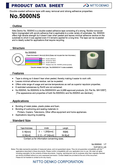
No.5000NS 1/710-P-0012_USDouble-coated adhesive tape with easy removal and strong adhesive propertiesNo.5000NSOutlineNitto Denko No. 5000NS is a double-coated adhesive tape consisting of a strong, flexible nonwoven fabric impregnated with acrylic adhesive that is applicable to a wide variety of substrates. No. 5000NS offers high tensile strength so it doesn ’t tear when peeled and leaves minimal adhesive residue on the substrate to which it was applied even if it remains applied for a long time. The tape can be re-peeled and is ideally suited for applications that require recycling.Structure* Double release liner type, “No.5000NSWH ” is also available .Features● Tape is strong so it doesn ’t tear when peeled, thereby making it easier to work with. ● Leaves minimal adhesive residue; can be re-peeled.● Offers wide range of usage and service temperatures as well as superior repulsion properties. ● 6 restricted substances by RoHS are not contained.● No.5000NS, No.5000NSU & No.5000NSWH are UL969 approved products. [UL File No. MH13557][The appearance and properties of both No.5000NSU and No.5000NS are identical.]Applications● Bonding of metal plates, plastic plates and foam. ● Bonding of cushioning and sealing materials in:Printers, Copiers, Televisions, Other office equipment and home appliances. ● Applications requiring re-peeling.Standard SizeContact us for information concerning sizes.Acrylic adhesive Nonwoven fabric Acrylic adhesiveRelease liner (No. 5000NS printed [purple])No.5000NS 2/710-P-0012_USProperties● Re-peeling propertiesPeeling properties Adhesive residue ○: Peels without tearing ○: No adhesive residue ×: Tears when peeled △: Some adhesive residue×: Large amount of adhesive residue[Peeling properties test method ][Adhesive residue test method ]Lining material: 5-mm(0.20 inch) thick urethane foam Tape thickness: 3 mm(0.12 inch) ,Curing condition: 60 degree C(140F) /90%RH x 15 days Peeling speed: 300 mm/min(12 inch/min), Peeling angle: 90 degreeTape area: 20 mm(0.79inch) Lining material: PET #25(1mil)Curing condition: 60 degree C(140F)/90%RH x 15 days Peeling speed: 300 mm/min(12 inch/min) Peeling angle: 180 degreeNo.5000NS SubstrateSubstrate10-P-0012_USShearing adhesive strength for each substratezBacking material: PET#25(1mil) Application condition:1 pass back and forth with a 2kg (4.41 lb) roller Bonding temperature: 23degreeC(73F)/50%RH Curing condition: 23degreeC(73F)/50%RH x 30 min Peeling speed: 300 mm/min (12 inch/min) Peeling angle: 180degreeMeasurement temperature: 23 degreeC(73F)/50%RHNo.5000NS 4/710-P-0012_US●Holding power(Unit: N/20mm)Substrate: Stainless steel plate Sample width: 20 mm(0.79 inch) Backing material: PET#25(1mil) Application condition:1 pass back and forth with a 2kg(4.41lb) roller Bonding temperature: 23degreeC(73F)/50%RH Curing condition:Measurement temperature x 30 min Peeling speed: 300 mm/min(12 inch/min)Peeling angle: 180 degree Measurement temperature:-30, -20, 0, 10, 23, 40, 60, 80, 100 degree C (-22.,-4.,32,50,73,104,140,176,212 F))Measurement temperature x 30minSubstratePET#25(1mil)No.5000NS 5/710-P-0012_US● Constant load peeling● Tape strength(Unit: mm)Substrate: Stainless steel plate Sample width: 20 mm(0.79 inch) Backing material: PET#25(1mil) Application condition:8 pass back and forth with a 2kg (4.41 lb.) roller Bonding temperature: 23degree C/50%RHCuring condition: 23degree C(73F)/50%RHx12 hrsMeasurement temperature: 23degreeC(73F)/50%RHLoading time: 12 hrs, 24 hrsNo.5000NSNo.5000NS 6/710-P-0012_US● 180 degree peeling strength-Curing under each environment after application (Durability)● 180 degree peeling strength - Aging after application● 180 degree peeling strength for each application pressureSubstrate: Stainless steel plate Sample width: 20mm(0.79 inch) Backing material: PET#25(1mil) Application condition:1 pass back and forth with a 2kg (4.41 lb.) roller Bonding temperature: 23degreeC(73F)/50%RH Curing condition: See the left tablePeeling speed: 300 mm/min(12 inch/min) Peeling angle: 180 degreeMeasurement temperature: 23degreeC(73F)/50%RH*1: Heat shock condition[-40degreeC(-40F)x30min ⇔90degreeC(194F)x 30min]x 100cycles*2: Heat cycle condition[-20degreeC(-4F) x 6hrs=>(1hr)=>60degreeC(140F)/95%RHx6hrs=>(1hr)=>]x40 cyclesSubstrate: Stainless steel plate Sample width: 20mm(0.79 inch) Backing material: PET#25(1mil) Application condition:1 pass back and forth with a2 kg(4.41 lb.) roller Bonding temperature: 23degreeC(73F)/50%RH Curing condition: 23degreeC(73F)/50%RH x 1min, 30min, 1hr, 4hrs, 8hrs, 24hrs, 72hrs Peeling speed: 300 mm/min(12 inch/min) Peeling angle: 180 degreeMeasurement temperature: 23degreeC(73F)/50%RHSubstrate: Stainless steel plate Backing material: PET#25(1mil) Application condition:1 pass back and forth with a 0.1 kg, 0.5 kg,2 kg, 5 kg (0.22lb,1.10lb,4.41lb,11.02 lb.)roller, Bonding temperature: 23degreeC(73F)/50%RH Curing condition:23degreeC(73F)/50%RHx30 min Peeling speed: 300 mm/min(12 inch/min) Peeling angle: 180degreeMeasurement temperature: 23degreeC(73F)/50%RHNo.5000NS 7/710-P-0012_USPrecautions when using●Remove all oil, moisture and dirt from the surface of the substrate before applying.●Since t he tape is pressure-sensitive adhesive, be sure to apply enough pressure with a roller or press when applying. Otherwise it might be affected to its properties and appearance.●The tape may not adhere well to extremely uneven or distorted surfaces. Enough Leveling off the surface should be required before applying.●It takes certain time to get full adhesive strength after applying, keep away the tape from any stress for a several hours after applying.Precautions when storing●Please be sure to keep the tape in its box when not using.●Please keep in a cool and dark place away from direct sunlight.Published in January 2011。
SDTGA5000工业分析仪说明书[1]1
![SDTGA5000工业分析仪说明书[1]1](https://img.taocdn.com/s3/m/b03038d950e2524de5187e37.png)
第一章仪器性能和特点1.1应用范围本仪器是长沙三德实业有限公司专利技术产品,适合在短时间内分析大批量煤样的水分、灰分、挥发分,并计算其固定碳含量和发热量。
可广泛应用于煤炭、电力、冶金、石化、地勘、环保、科研、学校等行业和部门。
1.2性能指标最大功率: <4.5kw;炉温范围:室温~1000℃;控温范围:室温~920℃;控温精度:恒温温度≤200±5℃;恒温温度>200±10℃;每盘煤样最大个数:水分/灰分:15个;挥发分:10个最大气流量:氮气10升(纯度99.9%),空气10升。
1.3仪器特点1、试验结果精密度、准确度高完全符合国标GB212—2001《煤的工业分析方法》的要求。
2、测试速度快、工作效率高SDTGA5000工业分析仪在同一时间可对15个试样进行分析,批量优势相当明显,可大大提高工作效率。
3、操作简便、安全可靠SDTGA5000工业分析仪不需要在开始做挥发分之前和做完挥发分之后打开恒温炉盖,对坩埚作加盖和取盖的操作,避免被高温烫伤及炉丝发出的红外线对操作人员眼睛的伤害。
在试验开始后的全部过程均由计算机控制,无需人工参与,且高温炉完全封闭在机内,操作人员不必担心高温所带来的危害,既安全又可靠。
4、界面友好、功能强大SDTGA5000工业分析仪系统在Windows操作平台上运行,全中文提示,界面友好,简单易学。
自动化程度高,能自动升温、恒温、降温、存储、处理试验数据;自动进行线性、系统偏差、样重校正;具有超温、热电偶断线、反接等自动报警和保护功能。
5、故障率低SDTGA5000工业分析仪结构设计合理,与国内同类产品相比故障率低,产品质量大大提高。
6、加热保温材料采用高温下不易氧化的新型合金加热材料,避免了普通电炉丝易氧化的现象,且升温速度快。
第二章仪器组成及工作原理2.1 仪器组成SDTGA5000工业分析仪由主机(内装电子分析天平)、充气设备、计算机(含显示器)及打印机组成。
SD5400中文资料
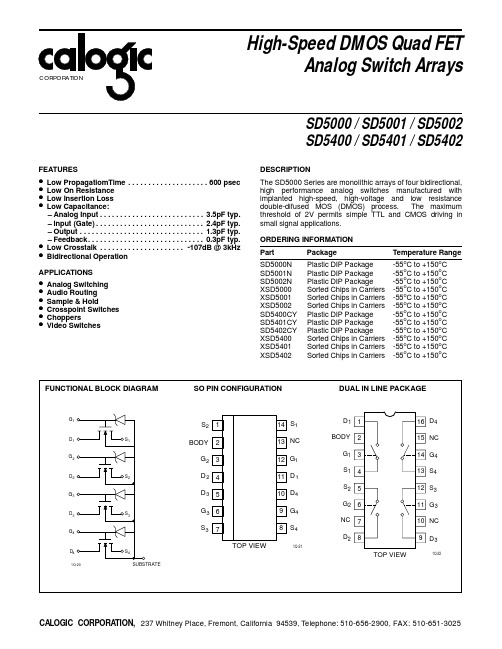
Leakage Current - SD5001/SD5401 IDS(OFF) ISD(OFF) IGBS Drain-Source Source-Drain Gate 1.0 1.0 10.0 10.0 1.0 nA nA µA VGS = VBS = -5V, VDS = 10V VGD = VBD = -5V, VSD = 10V VDB = VSB = 0V, VGB = 25V
G1
S2
S1
1 2
14 S1 13 NC 12 G1 11 D 1 10 D4 9
8 TOP VIEW G4 S4
D1 1
16 D4 15 NC 14 G4 13 S4 12 S3 11 G 3 10 NC 9
TOP VIEW D3
1Q-22
D1
BODY
BODY
G1 S1 S2
2 3 4 5
G2
G2 3
Leakage Current - SD5002/SD5402 IDS(OFF) ISD(OFF) IGBS VT Drain-Source Source-Drain Gate Threshold Voltage Drain-Source ON Resistance Match ON Resiatance 0.1 1.0 50 30 23 19 1 2.0 70 0.1 1.0 50 30 23 19 1 2.0 70 0.1 1.0 1.0 1.0 50 30 23 19 1 10.0 10.0 1.0 2.0 70 Ω Ω nA nA µA V VGS = VBS = -5V, VDS = 15V VGD = VBD = -5V, VSD = 15V VDB = VSB = 0V, VGB = 30V VDS = VGS = VT, VSB = 0V, ID = 1µA VGS = 5V, VSB = 0V, ID = 1mA VGS = 10V, VSB = 0V, ID = 1mA VGS = 15V, VSB = 0V, ID = 1mA VGS = 20V, VSB = 0V, ID = 1mA VGS = 5V
SD5000中文资料
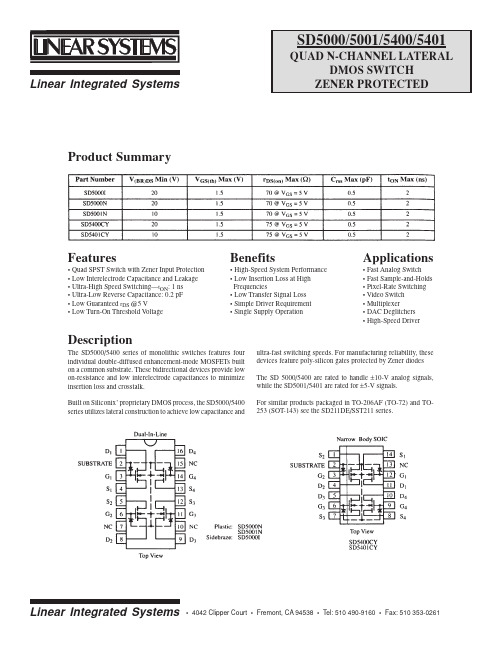
Benefits
• High-Speed System Performance • Low Insertion Loss at High Frequencies • Low Transfer Signal Loss • Simple Driver Requirement • Single Supply Operation
The SD5000/5400 series of monolithic switches features four individual double-diffused enhancement-mode MOSFETs built on a common substrate. These bidirectional devices provide low on-resistance and low interelectrode capacitances to minimize insertion loss and crosstalk. Built on Siliconix’ proprietary DMOS process, the SD5000/5400 series utilizes lateral construction to achieve low capacitance and ultra-fast switching speeds. For manufacturing y, these devices feature poly-silicon gates protected by Zener diodes The SD 5000/5400 are rated to handle ±10-V analog signals, while the SD5001/5401 are rated for ±5-V signals. For similar products packaged in TO-206AF (TO-72) and TO253 (SOT-143) see the SD211DE/SST211 series.
SD05C中文资料
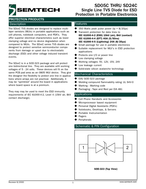
Symbol Ppk IPP VPP TL TJ TSTG
Value 350 24 30 260 (10 sec.) -55 to +125 -55 to +150
Units Watts
A kV °C °C °C
Electrical Characteristics
SD05C TVS for 5V Lines Parameter
Reverse Stand-Off Voltage Reverse Breakdown Voltage Reverse Leakage Current Clamping Voltage Clamping Voltage Junction Capacitance
Symbol VRWM VBR IR VC VC Cj
10
Peak Pulse Power - PPP (kW)
1
0.1
0.01 0.1
110 100
90 80 70 60 50 40 30 20 10
0 0
1
tp (µs)
1000
Pulse Waveform
Waveform Parameters:
tr = 8µs td = 20µs
Applications
u Cell Phone Handsets and Accessories u Microprocessor based equipment u Personal Digital Assistants (PDAs) u Notebooks, Desktops, & Servers u Portable Instrumentation u Pagers u Peripherals
They may may be used to meet the ESD immunity requirements of IEC 61000-4-2, Level 4 (15kV air, 8kV contact discharge).
SDZ5000 ACE软件培训

ACE数控测井地面系统培训软件部分目次1 概述 (1)1.1 系统特征 (1)2 安装与设置 (1)2.1 安装测井软件 (1)2.2 设置 (2)3 系统文件组织 (5)3.1 测井软件文件组织 (5)3.2 射孔取芯文件组织 (7)3.3 解释程序文件组织 (7)4 ACE软件操作介绍 (7)4.1 测井程序介绍 (7)5 附录 (15)5.1 附录1 记录点与零长记录点: (15)5.2 附录2ACE缆芯加电分配 (16)5.3 附录3 ACE信号分类及其处理板卡 (17)5.4 附录4 SZS2000三组合缆芯分配 (17)ACE数控测井地面系统培训软件部分1 概述1.1 系统特征我所的数控测井软件从SK88/SKH2000系列数控的最初研制,到SKD3000系列数控、SKS-3000射孔取芯、SDZ3000快速平台等的逐步完善,相继经历了将近20年的发展,积累了丰富的经验和技术资料。
我所最新研制的ACE数控测井地面系统软件(以下简称:ACE软件)正是伴随ACE数控测井地面系统的研制应运而生。
ACE软件是在吸取了前几代数控测井软件的成功经验的基础上,基于VISTA操作系统,利用先进的编程技术重新设计,具有多语言图形界面、人性化交互设计,操作方便、灵活、直观等特点。
该软件具有如下特征:·采用微软最新的.Net Framework平台重新设计,应用了目前应用广泛的XML语言、Access数据库。
·采用VISTA操作系统,多语言人性化图形操作界面,可中英文相互切换。
·采用直接DLIS格式记录,国际标准的数据记录格式,通用性强。
·具备系统诊断、远程监控等功能。
2 安装与设置ACE软件的安装包括:测井软件的安装和相关板卡驱动程序的安装。
将压缩的测井软件安装文件ACE.ZIP直接释放到D:\ACE目录中即可。
使用USB连接线将相关板卡与USB集线器相连,使用USB连接线将USB集线器与主机相连。
DS5000存储介绍
DS5000 Storage System 综述◆第七代体系结构设计提供了史无前例的性能,扩展性和灵活性◆最多支持16个主机端口◆灵活的设计可支持的4Gb/s FC, 8Gb/s FC, 和1Gb/s iSCSI主机接口混用◆支持RAID 0, 1, 3, 5, 6, 10 , 允许系统管理员灵活选择最适合用户环境和性能的数据保护方式◆支持在单个系统中通过混用高性能的FC硬盘和高容量的SATA硬盘建立分层次的存储◆全冗余的I/O 通路,自动故障切换,在线管理等设计保证了“始终在线”的数据可用性◆专用的数据Cache 和专用Cache镜像高速总线,意外掉电时,除电池保护外,还会将Cache数据写入专用的闪盘中Model – DS 5100和DS 5300控制器两个控制器–互为冗余并且支持热插拔Intel Xeon 2.8 GHzCPU缓存(单个控制器) 2GB数据缓存8GB,16GB,32GB,64GB前端主机接口最大16 X 4/8 Gbps FC后端磁盘通道16个4 Gbps最大磁盘数量448/ FC/SATA 或480 SATA支持硬盘类型FC:146GB,300GB,450GB 600GB 15KSATA :750GB,1TB 7.2KSSD:73GBRAID 级别0, 1, 3, 5, 6, 10存储分区可选择8,16,32,64,128,256或512个存储分区支持全局热备盘DS5000 存储管理软件IBM Storage Manager 版本10.10高级服务功能FlashCopy®, Enhanced Remote Mirroring, V olumeCopy电源和风扇冗余电源和风扇,支持热插拔,双电源输入扩展柜连接EXP5000 扩展柜–支持最大28个扩展柜连接(448 块硬盘)EXP5000 扩展柜包括16个硬盘插槽连接EXP5060 扩展柜–支持8个扩展柜连接(480块硬盘),每个扩展柜可配置最多60 块1TB硬盘DS5000 控制器(前视图)每个电源风扇模块包括:一个电源、两个风扇和一个电池充电器DS5000 控制器(后视图)DS5000 优势1.存储系统内部运行消耗的控制缓存与数据缓存分离设计。
- 1、下载文档前请自行甄别文档内容的完整性,平台不提供额外的编辑、内容补充、找答案等附加服务。
- 2、"仅部分预览"的文档,不可在线预览部分如存在完整性等问题,可反馈申请退款(可完整预览的文档不适用该条件!)。
- 3、如文档侵犯您的权益,请联系客服反馈,我们会尽快为您处理(人工客服工作时间:9:00-18:30)。
50 3.5 50 23 — 18
— — — — 0.2 —
— — — — — 200
V V V V mA —
Test Conditions
Value Min. Typ. Max.
Unit
POUT 1dB f = 1 GHz GP VSWR COB
:
VCC = 20 V VCC = 20 V VCC = 20 V VCB = 20 V
TEST CIRCUIT
B1, B2 : Ferrite Beads C1,C2 C3 C4 C5,C6 C7,C8 : 120 pF Chip Capacitor : .4 - 2.5 pF Johanson Capacitor : .8 - 8 pF Johanson Capacitor : 220 pF Chip Capacitor
C9,C10 : 1000 pF Chip Capacitor C11 : .1µF Capacitor C12,C13 : 15,000 pF EMI Filter L1,L2 : 5 Turn Choke; Wire Diameter .025", I.D. 0.125"
Substrate material: Er = 10.2, H
IC = 220 mA IC = 220 mA IC = 220 mA
1.5 9.5 — —
— — — —
— — 25:1 4.0
W dB — pF
f = 1 GHz f = 1 GHz f = 1 MHz
2/4
SD5000
IMPEDANCE DATA FREQ. 1000 MHz ZIN (Ω) 4.0 + j 3.3 ZCL (Ω) 20.8 + j 33.3
.280 4L STUD (M122) epoxy sealed ORDER CODE SD5000 BRANDING S10A015
PIN CONNECTION
DESCRIPTION The SD5000 is a NPN Silicon Transistor designed for high gain linear performance at 1000 MHz. This part uses gold metallized die and polysilicon site ballasting to achieve high reliability and ruggedness. The SD5000 can be used for applications such as Telecommunications, Radar, ECM, Space and other commercial and military systems. ABSOLUTE MAXIMUM RATINGS (T case = 25 ° C)
SD5000
RF & MICROWAVE TRANSISTORS GENERAL PURPOSE LINEAR APPLICATIONS
. . . . . . .
PRELIMINARY DATA
GOLD METALLIZATION EMITTER SITE BALLASTING INTERNAL INPUT MATCHING OVERLAY GEOMETRY METAL/CERAMIC PACKAGE COMMON EMITTER CONFIGURATION POUT = 1.5 W MIN. WITH 9.5 dB GAIN
= .050", 1oz. Copper
3ቤተ መጻሕፍቲ ባይዱ4
SD5000
PACKAGE MECHANICAL DATA Ref.: Dwg. No. 12-0122
Information furnished is believed to be accurate and reliable. However, SGS-THOMSON Microelectronics assumes no responsability for the consequences of use of such information nor for any infringement of patents or other rights of third parties which may results from its use. No license is granted by implication or otherwise under any patent or patent rights of SGS-THOMSON Microelectronics. Specifications mentioned in this publication are subject to change without notice. This publication supersedes and replaces all information previously supplied. SGS-THOMSON Microelectronics products are not authorized for use as critical components in life support devices or systems without express written approval of SGS-THOMSON Microelectonics. © 1994 SGS-THOMSON Microelectronics - All Rights Reserved SGS-THOMSON Microelectronics GROUP OF COMPANIES Australia - Brazil - France - Germany - Hong Kong - Italy - Japan - Korea - Malaysia - Malta - Morocco - The Netherlands Singapore - Spain - Sweden - Switzerland - Taiwan - Thailand - United Kingdom - U.S.A
Symbol Parameter Value Unit 1. Collector 2. Emitter 3. Base 4. Emitter
VCBO VCES VEBO IC PDISS TJ TSTG
Collector-Base Voltage Collector-Emitter Voltage Emitter-Base Voltage Device Current Power Dissipation Junction Temperature Storage Temperature
Symbol Test Conditions Value Min. Typ. Max. Unit
BVCBO BVEBO BVCES BVCEO ICBO hFE DYNAMIC
Symbol
IC = 10mA IE = 5mA IC = 10mA IC = 5mA VCB = 28V VCE = 5V IC = 100mA
4/4
50 50 3.5 1.0 7.0 +200 − 65 to +150
V V V A W °C °C
THERMAL DATA RTH(j-c) Junction-Case Thermal Resistance 25 °C/W
1/4
November 1992
SD5000
ELECTRICAL SPECIFICATIONS (T case = 25 ° C) STATIC
