ECS-180使用说明书V1.0121114
ECS用户手册
ECS上位机监控系统用户手册上位机监控系统用户手册日东电子发展(深圳)有限公司二〇一二年目录第一章概述 (2)第二章ECS功能介绍 (3)1.登录界面 (3)2.监控界面 (4)3.联机注册 (5)4.电子屏设置 (6)5.指令浏览 (7)第三章软硬件环境介绍 (8)第一章概述自动化仓储技术对于提高劳动生产率、降低生产成本、科学有序的组织生产有着非常重要的作用。
因此近几年来我国愈来愈多的企业采用自动化仓储技术对此,我公司参照国际先进水平,结合自动化控制领域传统的技术优势,研制了具有国内先进水平的自动化立体仓库,与我公司多年研制完善的技术相结合,提出了自动化仓储与厂区物流的整体解决方案。
立体仓库作为现代物流系统中的主要组成部分,是一种多层次存放货物的高架仓库系统,由自动控制与管理系统、货架、巷道式堆垛机、出入库输送机等设备构成,能按指令自动完成货物的搬运、存储作业,并能对库存货物进行自动管理、是企业现代化的重要手段之一。
自动化立体仓库管理系统采用流行的“客户服务器”方式,服务器用来存储仓库货物的各种信息,操作员以客户机完成出入库管理。
对于较大型的自动化立体仓库,各种自动化设备较多,它们的控制及各种设备迅速而协调的工作对于提高自动化仓库的效率十分重要。
因而设置专用的控制客户机,该控制计算机控制软件采用任务工作方式,各种设备可以并行且协调地运转。
堆垛机控制技术采用PLC与计算机相结合,使得堆垛机控制系统不但同时拥有高度的安全性、可靠性、完善的操作界面,同时也降低了控制系统的造价。
针对现场干扰强的特点,采取了完善的抗干扰措施和系统纠错技术。
为了进一步提高堆垛机的工作效率,堆垛机不但拥有很高的运动速度,同时对堆垛机取货、放货、加减速过程及认址的控制也是非常重要的。
我们在堆垛机认址时采用了三级减速技术,大幅度提高了认址效率。
第二章ECS功能介绍1.登录界面运行桌面上的“”图标,进入系统的登录界面,如下图所示:在登录界面里,录入正确的登录密码后,点登录,进入系统主监控界面。
ECS运行操作说明
ECS运行操作说明一.ECS的组成:ECS称为电气监控系统,主要的监视和控制范围为:发电机、变压器、高低压厂用系统。
ECS是整个DCS的一个组成部分,通过光纤和DCS实现通讯。
二.设备操作:ECS的设备操作可通过操作员站和后备硬手操作实现。
1.操作员站的操作:(1)合闸操作:在系统图中单击相应的设备,弹出手操器对话框;单击“合选择”、“合执行”,开关合闸,“合”红灯亮;单击“合选择”、“合取消”,取消合闸操作;单击“退出”,关闭手操器对话框。
(2)分闸操作:单击“跳选择”、“跳执行”,开关跳闸,“分”绿灯亮;单击“跳选择”、“跳取消”,取消分闸操作;单击“退出”,关闭手操器对话框。
2.硬手操盘上的操作:硬手操开关有五个位置:跳闸(0°)、就地(45°)、远控(90°)、就地(135°)、合闸(180°)。
正常情况下将开关置于“远控”位置。
合闸时,将开关打至“合闸”位置,然后将开关打至“远控”位置;分闸时,将开关打至“跳闸”位置,然后将开关打至“远控”位置。
合闸或分闸操作不成功,也要将开关打至“远控”位置。
说明:低压开关在合闸前,先进行分闸操作,使开关储能。
三.故障和事故处理:1.电气设备故障或事故处理:当设备运行中出现故障或事故后,在电脑上方出现光字报警,同时出现音响报警,在明确了故障及事故情况后,单击光字报警信息,音响、光字报警消失。
然后根据《运行规程》处理。
2.监控系统故障处理:(1)当操作员站显示的灯光指示及其它数据与实际设备运行位置、状态不相符,而电气一、二次设备运行正常时,运行人员及时通知工程师站管理人员进行处理,同时加强设备的监视与巡视。
需要操作时,在保护屏上用硬手操作开关操作。
(2)当电脑“死机”时,运行人员可重新启动计算机。
在“程序”中打开Hollysys Smartpro,在Facview Exlorer中打开Jhrd,单击“运行”图标,打开“电气系统”,进入操作界面。
ECS系列电流传感器说明书

ECS SeriesCurrent SensorAvailable Models:SensorType . . . . . . . . . . . . . . . . . . . . . . . . . . . . . . . . .Toroidal through hole wiringMode . . . . . . . . . . . . . . . . . . . . . . . . . . . . . . . .Over or undercurrent, switch selectable on the unit or factory fixedTrip Point Range . . . . . . . . . . . . . . . . . . . . . .0.5 - 50A in 3 adjustable ranges or fixed Tolerance Adjustable . . . . . . .Guaranteed rangeFixed . . . . . . . . . . . .0.5 - 25A: 0.5A or ±5% whichever is less; 26 - 50A: ±2.5%Maximum Allowable Current . . . . . . . . . . .Steady – 50A turns; Inrush – 300A turns for 10s Trip Point Hysteresis . . . . . ... . . .. . . . . . . .≅ ±5%Trip Point vs. Temperature . . . . . . . . . . . . .±5%Response Time . . . . . . . . . . . . . . . . . . . . . . . .≤ 75ms Frequency . . . . . . . . . . . . . . . . . . . . . . . . . . . .45/500 Hz Type of Detection . . . . . . . . . . . . . .. . . . . . . .Peak detection Trip DelayType . . . . . . . . . . . . . . . . . . . . . . . . . . . . . . . . .AnalogRange Adjustable . . . . . . . . . .0.150 - 7s; 0.5 - 50s (guaran teed ranges) Factory Fixed . . . . . . .0.08 - 50s (±20ms, whichever is greater)Delay vs. Temperature . . . . . . . . . . . . . . . . .±15%Sensing Delay on Startup . . . . . . . . . . . . . . .Factory fixed 0 - 6s: +40%, -0%InputVoltage . . . . . . . . . . . . . . . . . . . . . . . . . . . . . . . 24 , 120, or 230VAC; 12 or 24VDCTolerance 12VDC & 24VDC/AC . . . . . .-15 - 20% 120 & 230VAC . . . . . . . . . . . . .-20 - 10% AC Line Frequency . . . . . . . . . . . . . . . . . . . .50/60 Hz OutputType . . . . . . . . . . . . . . . . . . . . . . . . . . . . . . . . .Electromechanical relay Form . . . . . . . . . . . . . . . . . . . . . . . . . . . . . . . . .Isolated, SPDTRating . . . . . . . . . . . . . . . . . . . . . . . . . . . . . . .10A resistive @ 240VAC; 1/4 hp @ 125VAC; 1/2 hp @ 250VACLife . . . . . . . . . . . . . . . . . . . . . . . . . . . . . . . . . .Mechanical – 1 x 10⁶ ; Electrical – 1 x 10⁵ProtectionCircuitry . . . . . . . . . . . . . . . . . . . . . . . . . . . . .EncapsulatedIsolation Voltage . . . . . . . . . . . . . . . . . . . . . .≥ 2500V RMS input to output Insulation Resistance . . . . . . . . . . . . . . . . . . .≥ 100 MΩ MechanicalMounting . . . . . . . . . . . . . . . . . . . . . . . . . . . .Surface mount with two #6 (M3.5 x 0.6) screws Dimensions . . . . . . . . . . . . . . . . . . . . . . . . . . .3.5 x 2.5 x 1.75 in. (88.9 x 63.5 x 44.5 mm)Termination . . . . . . . . . . . . . . . . . . . . . . . . . .0.25 in. (6.35 mm) male quick connect terminals (5)EnvironmentalOperating / Storage Temperature . . . . . . .-40° to 60°C / -40° to 85°C Humidity . . . . . . . . . . . . . . . . . . . . . . . . . . . . .95% relative, non-condensing Weight . . . . . . . . . . . . . . . . . . . . . . . . . . . . . . .≅ 6.4 oz (181 g)Features:• Toroidal through hole wiring • 0.5 - 50A trip points• Adjustable or factory fixed trip delays • Isolated, 10A, SPDT output contacts • 5% trip point hysteresis (dead band)Approvals:Auxiliary Products:• Female quick connect: P/N: P1015-13 (AWG 10/12)P/N: P1015-64 (AWG 14/16) P/N: P1015-14 (AWG 18/22)SpecificationsOrder Table:XSeries─ECS - Selectable over or undercurrent sensing ─ECSH - Overcurrent sensing ─ECSL - Undercurrent sensingXInput─1 - 12VDC ─2 - 24VAC ─3 - 24VDC ─4 - 120VAC ─6 - 230VACXTrip Point─Fixed - Specify 2-50A in 1A increments─0 - 0.5-5A adjustable ─1 - 2-20A adjustable ─H - 5-50A adjustableXTrip Delay─F - Specify: 0.08-50s factory fixed─A - 0.150-7s adjustable ─B - 0.5-50s adjustableXSensing Delay on Start Up─Blank - 0s ─C - 1s ─D - 2s ─E - 3s ─F - 4s ─G - 5s ─H - 6sECS20BC ECS21BC ECS21BH ECS2HBC ECS30AC ECS40A ECS40AC ECS40BC ECS40BD ECS41A ECS41AC ECS41BC ECS41BD ECS41BH ECS41F.08ECS4HBC ECS4HBH ECS60AH ECS60BC ECS61BC ECS6HAHECSH21F.08C ECSH30AC ECSH3HF0.08D ECSH40AC ECSH40AD ECSH41AD ECSH41BC ECSH41F.08D ECSH4HF.08D ECSH61AD ECSL31A ECSL40AC ECSL40B ECSL40BH ECSL41A ECSL41AD ECSL45F7ECSL4HBH ECSL61AH ECSL6HAC The ECS Series of single-phase AC current sensors is a universal, overcurrent or undercurrent sensing control. Its built-in toroidal sensor eliminates the inconvenience of installing a stand-alone current transformer. Includes onboard adjustments for current sensing mode, trip point, and trip delay. Detects over or undercurrent events like; locked rotor, loss of load, an open heater or lamp load, or proves an operation is taking place or has ended.For more information see:Appendix B, page 166, Figure 20 for dimensional drawing.Appendix C, page 169, Figure 17 for connection diagram.OperationInput voltage must be supplied at all times for proper operation. When a fault is sensed throughout the trip delay, the output relay is energized. When the currentreturns to the normal run condition or zero, the output and the delay are reset. If a fault is sensed and then corrected before the trip delay is completed, the relay will not energize and the trip delay is reset to zero.AdjustmentSelect the desired function, over or under current sensing. Set the trip point and trip delay to approximate settings. Apply power to the ECS and the monitored load. Turn adjustment and watch the LED. LED will light; turn slightly in opposite direction until LED is off. Adjustment can be done while connected to the control circuitry if the trip delay is set at maximum. To increase sensitivity, multiple turns may be made through the ECS’s toroidal sensor. The trip point range is divided by the number of turns through the toroidal sensor to create a new range. When using an external CT, select a 2VA, 0-5A output CT rated for the current to be monitored. Select ECS adjustment range 0. Pass one secondary wire lead through the ECS toroid and connect the secondary leads together.If desired part number is not listed, please call us to see if it is technically possible to build .NC = Normally Closed Contact A = Sensing Delay On Start Up TD = Trip DelayR = ResetOC = Monitored Cur rentAFFB9L; HLMU; SCR9LLLC4; LLC6; PLSECS; ECSWAppendix B - Dimensional DrawingsFIGURE 15FIGURE 16FIGURE 18DCSAFIGURE 22inches (millimeters)(ECS has spade connectors andECSW has terminal board)FIGURE 15 - HLV Series FIGURE 16 - KVM SeriesV = VoltageL = LEDS = Undervoltage SetpointNO = Normally OpenNC = Normally ClosedC = Common, Transfer ContactL1N/L2FIGURE 17 - ECS SeriesV = VoltageI> = OvercurrentI< = UndercurrentFIGURE 18 - ECSW SeriesMC = Motor ContactorM = MotorF = FusesOL = OverloadRSW = Reset SwitchPositiveSwitchingNegativeSwitchingSinkingSourcingFIGURE 19 - TCS SeriesFIGURE 20 - TCSA SeriesZ = Zero AdjustS = Span AdjustW = Insulated Wire Carrying Monitored CurrentPLC = PLC Analog Input or Meter InputAppendix C - Connection DiagramsW = Insulated WireCarrying Monitored CurrentRelay contacts are isolated .FSW = Fan or Float ContactsCR = Control RelayCS = Current SensorMCC = Motor Contactor CoilI> = Adjustable OvercurrentI< = Adjustable UndercurrentW = Monitored Wire∆T - Adjustable Trip DelayL = LoadV = VoltagePS = Power SupplyPLC = PLC Digital Input Module。
ECS系统操作说明
马莲台电厂电气监控画面操作说明1.发变组系统监控:母线联络断路器及其隔离闸刀:只可监视,不可操作。
当开关为红颜色时表示闭合,绿颜色表示断开;当隔离闸刀为红颜色并显示闭合状态时表示闭合,当隔离闸刀为绿颜色并显示断开状态时表示断开。
发变组330KV主开关及其隔离闸刀:均可监控。
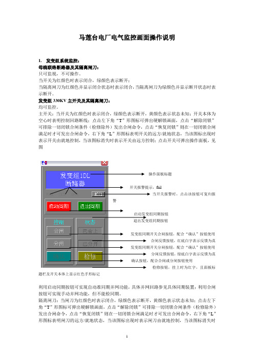
主开关:当开关为红颜色时表示闭合,绿颜色表示断开,黄颜色表示状态未知;开关本体为空心时表明控制回路断线;点击左下角“T”形图标可弹出硬解锁画面,点击“解除闭锁”可排除一切闭锁合闸条件(检修除外)发出合闸命令,点击“恢复闭锁”则在一切闭锁合闸满足时才可发出合闸命令,右下角“L”形图标表明开关的远方/就地状态,当该图标出现时表示开关由就地控制,当该图标消失时表示开关由远方控制;点击开关可弹出操作面板,见图操作面板标题fail当开关报警时,点击该按钮可复归报警启动发变组同期按钮退出发变组同期按钮发变组同期开关合闸按钮,配合“确认”按钮使用合闸反馈按钮,红底白字表示反馈为真发变组同期开关分闸按钮,配合“确认”按钮使用分闸反馈按钮,绿底白字表示反馈为真确认按钮,配合合闸或分闸按钮使用检修按钮,挂上时为红字,且面板标题栏及开关本体上显示红色手形标记利用启动同期按钮可实现自动准同期并网功能,具体并网回路参见具体同期装置;利用合闸按钮可实现手动并网功能,但不能检同期。
隔离闸刀:当闸刀为红颜色时表示闭合,绿颜色表示断开,黄颜色表示状态未知;点击左下角“T”形图标可弹出硬解锁画面,点击“解除闭锁”可排除一切闭锁合闸条件(检修除外)发出合闸命令,点击“恢复闭锁”则在一切闭锁合闸满足时才可发出合闸命令,右下角“L”形图标表明闸刀的远方/就地状态,当该图标出现时表示闸刀由就地控制,当该图标消失时表示闸刀由远方控制;点击闸刀可弹出操作面板,见图标注同上同时,在闸刀本体附近有三相状态指示灯,分别显示闸刀A,B,C三相分合状态,红色时表示对应相为合状态,绿色时表示对应相为分状态。
ECS操作说明
张家港沙洲电厂2×600MW机组DCS系统ECS系统操作员使用手册编写:俞文胜审核:戴钢批准:曹在基上海福克斯波罗有限公司2005年6月一.编制说明:1.本说明书意在使运行人员熟悉ECS系统的人机界面和基本操作方法。
2.由于ECS操作画面为DAS画面的一个组成部分,故DAS说明书中已涉及的内容在此不再详细说明。
3.本说明书实质上只能为操作员运行时提供参考,实际操作方法应按运行规程实施。
4.ECS的逻辑功能、联锁方式、保护功能等均以设计院和电厂的要求为设计依据,设计联络会已对此进行了审核。
现场调试时,有关方面将进一步按设计院和电厂的要求审核设计的合理性及组态的正确性。
而本说明书只涉及操作方法,不讨论ECS的逻辑功能、联锁方式、保护功能。
二.范围:●ECS涉及厂用电快速切换装置、电源断路器、微机同期装置和发电机启停等的控制操作。
操作画面为运行人员提供人机界面。
●画面分为弹出画面(由运行人员点击DAS画面中相应设备而弹出)和禁操成组画面。
三.典型操作:3.1.快速切换装置:单击“工切备”或“备切工”按钮,画面出现确认“ACK”按钮,单击“ACK”按钮,系统将对块切装置发出切换指令。
单击“复归”按钮,系统将发出复归指令。
单击“闭锁”按钮,系统将切换出口闭锁指令,按钮上将根据出口闭锁情况显示红色或底色背景。
单击“并联/同时”按钮,系统将发出并联/同时切换指令,按钮上将显示当前并联/同行状态。
单击画面中方框,将弹出另一画面,显示本装置相关状态。
3.2.断路器:普通断路器的操作面板由“合闸”、“分闸”和“ACK”按钮组成。
单击“合闸”或“分闸”按钮,画面出现确认“ACK”按钮,单击“ACK”按钮,系统将发出3秒钟的操作设备的短脉冲。
在系统发出操作脉冲时,“ACK”按钮同时被点亮。
若此断路器存在合闸条件或相关状态,面板上出现一个方框,单击画面中方框,将弹出另一画面,显示本断路器合闸条件或相关状态。
若此断路器存在复归、闭锁操作,面板上将出现相应按钮。
ECS-180使用说明书V1.0121114
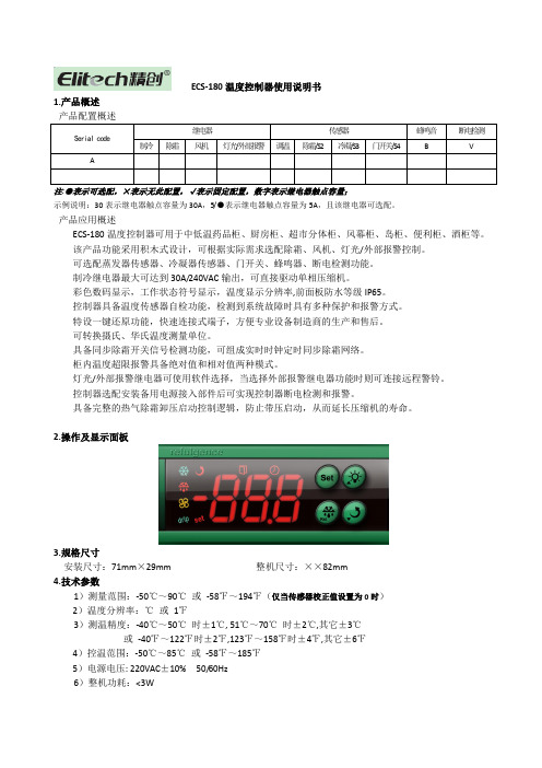
ECS-180温度控制器使用说明书1.产品概述Serial code继电器传感器蜂鸣音断电检测制冷除霜风机灯光/外部报警调温除霜/S2冷凝/S3门开关/S4B VA注:●表示可选配,×表示无此配置,√表示固定配置,数字表示继电器触点容量;示例说明:30表示继电器触点容量为30A,5/●表示继电器触点容量为5A,且该继电器可选配。
产品应用概述ECS-180温度控制器可用于中低温药品柜、厨房柜、超市分体柜、风幕柜、岛柜、便利柜、酒柜等。
该产品功能采用积木式设计,可根据实际需求选配除霜、风机、灯光/外部报警控制。
可选配蒸发器传感器、冷凝器传感器、门开关、蜂鸣器、断电检测功能。
制冷继电器最大可达到30A/240VAC输出,可直接驱动单相压缩机。
彩色数码显示,工作状态符号显示,温度显示分辨率,前面板防水等级IP65。
控制器具备温度传感器自检功能,检测到系统故障时具有多种保护和报警方式。
特设一键还原功能,快速连接式端子,方便专业设备制造商的生产和售后。
可转换摄氏、华氏温度测量单位。
具备同步除霜开关信号检测功能,可组成实时时钟定时同步除霜网络。
柜内温度超限报警具备绝对值和相对值两种模式。
灯光/外部报警继电器可使用软件选择,当选择外部报警继电器功能时则可连接远程警铃。
控制器选配安装备用电源接入部件后可实现控制器断电检测和报警。
具备完整的热气除霜卸压启动控制逻辑,防止带压启动,从而延长压缩机的寿命。
2.操作及显示面板3.规格尺寸安装尺寸:71mm×29mm 整机尺寸:××82mm4.技术参数1)测量范围:-50℃~90℃或-58℉~194℉(仅当传感器校正值设置为0时)2)温度分辨率:℃或1℉3)测温精度:-40℃~50℃时±1℃, 51℃~70℃时±2℃,其它±3℃或-40℉~122℉时±2℉,123℉~158℉时±4℉,其它±6℉4)控温范围:-50℃~85℃或-58℉~185℉5)电源电压: 220VAC±10% 50/60Hz6)整机功耗:<3W7)外部备用电源电压:~8)输入端口:柜温传感器、蒸发器传感器、冷凝器传感器、门开关(门打开时,传感器输出常开信号) 910)前面板防护等级:IP6511)工作环境温度:0℃~55℃12)存储温度:-25℃~75℃13)相对湿度:20%~85%(无结露)5.6.注①:仅在柜温传感器正常时有效。
3#机单元ECS功能说明书
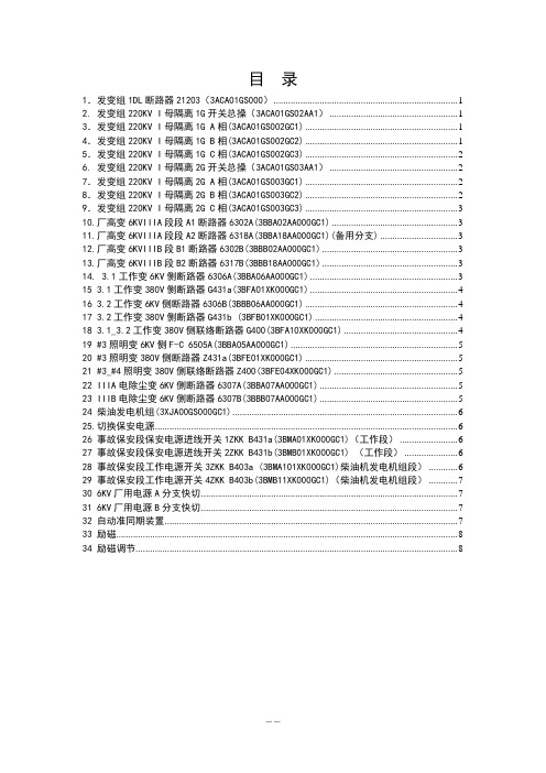
目录1.发变组1DL断路器21203(3ACA01GS000) (1)2. 发变组220KV I母隔离1G开关总操(3ACA01GS02AA1) (1)3.发变组220KV I母隔离1G A相(3ACA01GS002GC1) (1)4.发变组220KV I母隔离1G B相(3ACA01GS002GC2) (1)5.发变组220KV I母隔离1G C相(3ACA01GS002GC3) (2)6. 发变组220KV I母隔离2G开关总操(3ACA01GS03AA1) (2)7.发变组220KV I母隔离2G A相(3ACA01GS003GC1) (2)8.发变组220KV I母隔离2G B相(3ACA01GS003GC2) (2)9.发变组220KV I母隔离2G C相(3ACA01GS003GC3) (3)10.厂高变6KVIIIA段段A1断路器6302A(3BBA02AA000GC1) (3)11.厂高变6KVIIIA段段A2断路器6318A(3BBA18AA000GC1)(备用分支) (3)12.厂高变6KVIIIB段B1断路器6302B(3BBB02AA000GC1) (3)13.厂高变6KVIIIB段B2断路器6317B(3BBB18AA000GC1) (3)14. 3.1工作变6KV侧断路器6306A(3BBA06AA000GC1) (3)15 3.1工作变380V侧断路器G431a(3BFA01XK000GC1) (4)16 3.2工作变6KV侧断路器6306B(3BBB06AA000GC1) (4)17 3.2工作变380V侧断路器G431b (3BFB01XK000GC1) (4)18 3.1_3.2工作变380V侧联络断路器G400(3BFA10XK000GC1) (4)19 #3照明变6KV侧F-C 6505A(3BBA05AA000GC1) (5)20 #3照明变380V侧断路器Z431a(3BFE01XK000GC1) (5)21 #3_#4照明变380V侧联络断路器Z400(3BFE04XK000GC1) (5)22 IIIA电除尘变6KV侧断路器6307A(3BBA07AA000GC1) (5)23 IIIB电除尘变6KV侧断路器6307B(3BBB07AA000GC1) (5)24 柴油发电机组(3XJA00GS000GC1) (6)25.切换保安电源 (6)26 事故保安段保安电源进线开关1ZKK B431a(3BMA01XK000GC1)(工作段) (6)27 事故保安段保安电源进线开关2ZKK B431b(3BMB01XK000GC1) (工作段) (6)28 事故保安段工作电源开关3ZKK B403a (3BMA101XK000GC1)柴油机发电机组段) (6)29 事故保安段工作电源开关4ZKK B403b(3BMB11XK000GC1)(柴油机发电机组段) (7)30 6KV厂用电源A分支快切 (7)31 6KV厂用电源B分支快切 (7)32 自动准同期装置 (7)33 励磁 (8)34 励磁调节 (8)1.发变组1DL断路器21203(3ACA01GS000)1)保护分闸:●灭磁开关分闸(3MKC01AA000GH1) XG01 &●#3机励磁机励磁电压(3MKC01EE001CE21)<1562)自动合闸:●发变组1DL断路器自动准同期合闸(3CBP01GH001GH3)注:增加联锁投退按钮,当投联锁时允许发变组1DL断路器21203自动合闸和自动分闸,否则不允许联锁动作。
ECS功能说明书新

酒钢热电厂#2机组EDPF-NT DCS系统ECS功能设计说明书(FAT版)甘肃电力试验研究所二OO五年五月一、基本介绍本工程电气控制系统分为两个部分:单元电气控制系统、公用电气控制系统。
单元电气控制系统在4号控制器实现,公用电气系统与循环水泵公用系统由5号控制器实现。
公用系统控制器CPU站上有4块以太网卡,分别与#1和#2单元DCS系统上位机通讯,公用系统设备操作指令有两套,其中一套为#1机组操作指令,另一套为#2机组操作指令,运行人员在画面上可以进行#1单元或#2单元操作选择,两套指令相互闭锁。
单元控制系统主要有:发电机变压器组系统、高压厂用变压器系统、6KV厂用电系统、低压厂用变压器系统、直流系统、不停电电源系统。
公用电气系统主要有:启动/备用变压器系统、低压公用变压器系统。
二、电机变压器组系统1.相关设备主变110kV断路器灭磁开关AVR励磁装置未完成主变110kV侧隔离开关6G同期开关(K1)2.设备操作2.1 顺控功能升压顺控:所有条件均包括“升压自动”状态。
步一:条件:无“AVR PT断线”(E01EX023非)且无“AVR 输入电源掉电”(E01EX025非)且灭磁开关在分位E01EX030且无“灭磁柜控制电源消失”(E01EX031非)且无“AVR 手动运行”(E01EX013非)且至少有两个功率柜无故障信号E01EX100且汽机转速>2990rpm且无AVR CHI故障(E01EX014非)。
指令:顺控投入A VR CHI。
步二:条件:无AVR CHII故障(E01EX015非)时,投CHI超时报警;指令:顺控投入A VR CHII。
步三:条件:A VR CHI(E01EX011)运行或A VR CHII(E01EX012)运行;指令:灭磁开关程控预合请求。
步四:条件:灭磁已预合;指令:灭磁开关程控合闸请求。
步五:条件:灭磁开关合闸状态E01EX029;指令:顺控升压励磁。
ECS系列串口服务器说明书(完整版)

ECS系列系列串口设备联网服务器串口设备联网服务器RS232/422/485Serial Device Server用户手册User’s Manual上海炽晟电子科技有限公司2010年4月第一章第一章 概述概述::1.1 1.1 产品介绍产品介绍产品介绍::ECS8100系列串口设备联网服务器(以下简称:串口服务器)是我公司自主研发的RS-232/422/485串口终端设备联网产品。
采用32位RM 处理器,结合高效的嵌入式系统,使设备运行更加安全、稳定。
ECS8100系列串口服务器让您无需投入大量资金来进行更换或升级,就可以让原有的RS-232/422/485串口设备立即具备网络互联能力。
而且可以把ECS8100系列串口服务器通过以太网链接到Unix/Linux 主机上,并通过以太网使用TCP/IP 提供TTY 服务的串口服务器。
ECS8100系列串口服务器使用了反向TELNET 登陆主机,提供Unix/Linux 的固定端口号驱动,可以让用户为每个终点接口制定一个固定的TTY/COM 端口。
为串口数据信息提供高效、安全、稳定的数据通道。
ECS8100系列被广泛应用于通信、控制领域,如银行前置终端机、电力监控、机房监控、PLC、智能电表、煤气表、生物识别装置、读卡器等环境,是连接串口设备及TCP/IP 以太网络的桥梁。
1.2功能特点功能特点::以太网口为10/100M 自适应,亦可手动配置; 操作模式丰富,满足不同行业应用; 采用32位高性能处理器,产品运行稳定; 友好的中文或英文菜单配置界面; 可用WEB 浏览器进行参数配置; 提供Windows 实COM 口驱动;支持通用Socket操作模式,包括TCP Server/Clint和UDP模式; 支持2台串口服务器背靠背Pair连接;支持RS232/422/485三合一串口界面,并软件可选; 提供UNIX 和LINUX 固定TTY 驱动;1.3串口联网服务器串口联网服务器的四大应用的四大应用的四大应用::TCP/UDP Real port (Windows 扩展串口模式扩展串口模式))基于Windows 平台下的扩展串口(com )驱动,并提供简洁易用的Windows 平台下的管理程序,在WindowsNT/Windows2000/WindowsXP/Windows2003下可最多达1024个串口。
ECS-180使用说明书
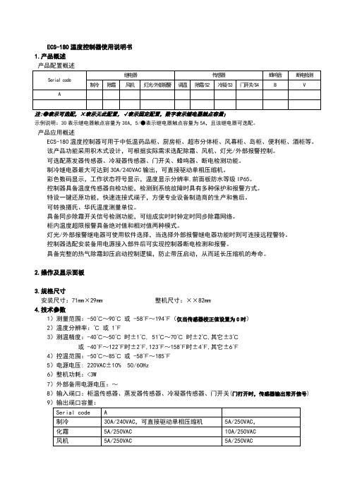
ECS-180温度控制器使用说明书1.产品概述产品配置概述Serial code继电器传感器蜂鸣音断电检测制冷除霜风机灯光/外部报警调温除霜/S2冷凝/S3门开关/S4 B VA注:●表示可选配,×表示无此配置,√表示固定配置,数字表示继电器触点容量;示例说明:30表示继电器触点容量为30A,5/●表示继电器触点容量为5A,且该继电器可选配。
产品应用概述ECS-180温度控制器可用于中低温药品柜、厨房柜、超市分体柜、风幕柜、岛柜、便利柜、酒柜等。
该产品功能采用积木式设计,可根据实际需求选配除霜、风机、灯光/外部报警控制。
可选配蒸发器传感器、冷凝器传感器、门开关、蜂鸣器、断电检测功能。
制冷继电器最大可达到30A/240VAC输出,可直接驱动单相压缩机。
彩色数码显示,工作状态符号显示,温度显示分辨率,前面板防水等级IP65。
控制器具备温度传感器自检功能,检测到系统故障时具有多种保护和报警方式。
特设一键还原功能,快速连接式端子,方便专业设备制造商的生产和售后。
可转换摄氏、华氏温度测量单位。
具备同步除霜开关信号检测功能,可组成实时时钟定时同步除霜网络。
柜内温度超限报警具备绝对值和相对值两种模式。
灯光/外部报警继电器可使用软件选择,当选择外部报警继电器功能时则可连接远程警铃。
控制器选配安装备用电源接入部件后可实现控制器断电检测和报警。
具备完整的热气除霜卸压启动控制逻辑,防止带压启动,从而延长压缩机的寿命。
2.操作及显示面板3.规格尺寸安装尺寸:71mm×29mm 整机尺寸:××82mm4.技术参数1)测量范围:-50℃~90℃或 -58℉~194℉(仅当传感器校正值设置为0时)2)温度分辨率:℃或 1℉3)测温精度:-40℃~50℃时±1℃, 51℃~70℃时±2℃,其它±3℃或 -40℉~122℉时±2℉,123℉~158℉时±4℉,其它±6℉4)控温范围:-50℃~85℃或 -58℉~185℉5)电源电压: 220VAC±10% 50/60Hz6)整机功耗:<3W7)外部备用电源电压:~8)输入端口:柜温传感器、蒸发器传感器、冷凝器传感器、门开关(门打开时,传感器输出常开信号) 9Serial code A制冷30A/240VAC,可直接驱动单相压缩机5A/250VAC,化霜5A/250VAC 10A/250VAC风机5A/250VAC 5A/250VAC10)前面板防护等级:IP6511)工作环境温度:0℃~55℃12)存储温度:-25℃~75℃13)相对湿度:20%~85%(无结露)5.6.注①:仅在柜温传感器正常时有效。
EX180系列设备网络连接器商品说明书
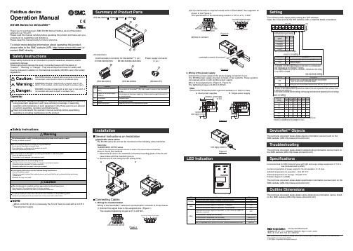
<EX180-SDN3/-SDN4/-SDN5/-SDN6>InstallationGeneral Instructions on InstallationApplicable valve seriesThe EX180 series SI unit can be mounted on the following valve manifolds.•ManifoldsSJ2000/3000, S0700 series∗: Refer to the catalogues and operation manuals for details on the solenoid valves and manifolds.•How to mount the manifold1. Mount the SI unit to the manifold so that the mounting guide of the SI unit case mates with the manifold groove.2. Secure the SI unit using the two sliding locks.LED IndicationCommunication connector for DeviceNet TM (1pc.)(EX180-CDN1)(EX180-CDN2)EX180-SDN3/4/5/6EX180-SDN3A/4A/5A/6A Power supply connector(1 pc.)(EX180-CP1)<Accessories>(2)A bus termination is required at both ends of DeviceNet TM bus segment as shown in the Figure 2.The specification of the terminating resistor is 121 Ω±1%, 1/4 W.Figure 2(3)How to connect.Figure 32. Wiring of the power supplyConnect the power supply to the power supply connector (1 pc.).The EX180 power supply structure consists of two systems. These systems can operate alone or with another power supply.Wire to the assigned pins. (Figure 4, Figure 5)The tightening torque is 0.22 to 0.25 Nm.•NoteGround the FG terminal with a ground resistance of 100 Ω or less.Solenoid valvepower supply 24 VDCDeviceNet power supply24 VDCFigure 4A. Dual power suppliesB. Single power supplyFigure 5Turn off the power supply while setting the DIP switches.Open the cover and set the DIP switches with a small flat blade screwdriver.Connecting Cables1. Wiring for communicationWiring of the DeviceNet TM cable and communication connector is shown below.(1)Connect the signal lines to the assigned pins. (Figure 1)The required tightening torque is 0.5 to 0.6 Nm.Figure 1SettingNOTEWhen conformity to UL is necessary the SI unit must be used with a UL1310Class2 power supply.Fieldbus deviceOperation ManualEX180 Series for DeviceNet TMThank you for purchasing an SMC EX180 Series Fieldbus device (Hereinafter referred to as "SI unit").Please read this manual carefully before operating the product and make sure you understand its capabilities and limitations.Please keep this manual handy for future reference.To obtain more detailed information about operating this product,please refer to the SMC website (URL ) or contact SMC directly.These safety instructions are intended to prevent hazardous situations and/or equipment damage.These instructions indicate the level of potential hazard with the labels of"Caution", " Warning" or "Danger". They are all important notes for safety and must be followed in addition to International standards (ISO/IEC) and other safety regulations.OperatorTroubleshootingThe technical document states detail troubleshooting information can be found on the SMC website (URL )SpecificationsConnected load: 24VDC Solenoid valve with light and surge voltage suppressor of 1 W orless (manufactured by SMC)Current consumption of power supply for SI unit operation: 0.1 A max.Ambient temperature for operation: -10 to 50 ℃C Ambient temperature for storage: -20 to 60 C℃Pollution degree 2: (UL508)The technical document states detail specification information can be found on the SMC website (URL )Outline DimensionsThe technical document states detail outline dimensions information can be found on the SMC website (URL )DeviceNet TM ObjectsThe technical document states detail objects information can be found on the SMC website (URL )Akihabara UDX 15F , 4-14-1, Sotokanda, Chiyoda-ku, Tokyo 101-0021, JAP AN URL 。
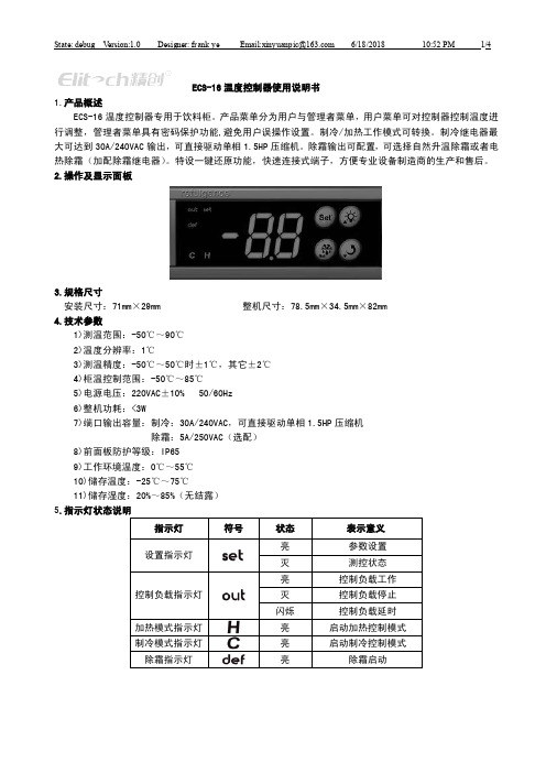
ECS-16使用说明书V1.0
ECS-16温度控制器使用说明书1.产品概述ECS-16温度控制器专用于饮料柜。
产品菜单分为用户与管理者菜单,用户菜单可对控制器控制温度进行调整,管理者菜单具有密码保护功能,避免用户误操作设置。
制冷/加热工作模式可转换。
制冷继电器最大可达到30A/240VAC输出,可直接驱动单相1.5HP压缩机。
除霜输出可配置,可选择自然升温除霜或者电热除霜(加配除霜继电器)。
特设一键还原功能,快速连接式端子,方便专业设备制造商的生产和售后。
2.操作及显示面板3.规格尺寸安装尺寸:71mm×29mm 整机尺寸:78.5mm×34.5mm×82mm4.技术参数1)测温范围:-50℃~90℃2)温度分辨率:1℃3)测温精度:-50℃~50℃时±1℃,其它±2℃4)柜温控制范围:-50℃~85℃5)电源电压:220VAC±10% 50/60Hz6)整机功耗:<3W7)端口输出容量:制冷:30A/240VAC,可直接驱动单相1.5HP压缩机除霜:5A/250VAC(选配)8)前面板防护等级:IP659)工作环境温度:0℃~55℃10)储存温度:-25℃~75℃11)储存湿度:20%~85%(无结露)5.指示灯状态说明指示灯符号状态表示意义设置指示灯亮参数设置灭测控状态控制负载指示灯亮控制负载工作灭控制负载停止闪烁控制负载延时加热模式指示灯亮启动加热控制模式制冷模式指示灯亮启动制冷控制模式除霜指示灯亮除霜启动6.参数表 菜单 菜单功能 设定范围H1 H2 单位用户菜单项St 设置温度 设置温度最小限定值C3~设置温度最大限定值C4 4 3 ℃ Po 菜单密码 0~99(密码为55且不可更改)/管理者菜单项rd 温度回差 1~15 3 6 ℃C1 温度传感器校正 -10~10 -1 -3 ℃ C2 控制输出启动延时 0~60 3 2 min C3 设置温度最小限定值 -50~St 2 0 ℃ C4 设定温度最大限定值St ~85106℃A1 传感器故障后周期开启时间 1~6015 45 min A2 传感器故障后周期关闭时间0~60 0:传感器故障后控制负载关闭 10 15 min d1 除霜周期 0~90 0:禁止除霜 612 hourd2 除霜时间 1~90 20 20 min d3 除霜过程显示0:显示柜温 1:除霜时显示dF2:除霜时显示除霜启动时柜温22/HC 制冷/加热模式转换 0:制冷 1:加热0 0 /7. 按键功能 7.1按键名称按键名称 作用Set进入参数设置状态 切换菜单和参数调整菜单及参数调整菜单及参数 持续10秒执行参数一键还原退出参数设置状态 退出一键还原状态 强制启动除霜7.2按键操作 1)用户参数设置测控状态下,按Set 键3S 进入用户参数设置状态,数码管显示菜单项St ,此时按Set 键显示对应参数值,按、键调整设置温度,再按Set 键返回菜单项St 。
数控折弯机简易数控系统SNC181说明书操作手册簿

SNC-18剪折机床数控系统用户手册V-1.20淦元自动化.ganyuan168.联系方式:目录第1章简介 (4)第2章规格说明 (5)2.1 显示 (5)2.2 电气规格 (5)2.3 环境温度 (5)第3章安装和接线 (6)3.1 安装与配线注意事项 (6)3.2 安装方向与空间 (6)3.3 安装环境 (6)3.4 外型尺寸 (6)3.5 前面板 (7)3.5.1 输入输出指示灯 (8)3.5.2 操作按键 (8)3.6 后面板 (9)3.6.1 系统电源端 (9)3.6.2 输入输出信号端 (9)3.6.3 编码器接口 (10)3.7 电气设计典型应用举例 (10)第4章系统调试 (11)4.1 调试前准备 (11)4.2 调试 (11)4.3 实际加工 (11)第5章操作说明 (12)5.1 密码保护 (12)5.2 示教功能说明 (12)5.3 断电记忆功能 (13)5.4 修改当前位置操作 (13)5.5 各种操作流程说明 (14)第6章系统参数 (16)6.1 参数说明 (16)6.2 SNC-18B参数表 (19)6.3 SNC-18C参数表 (20)附录一:报警信息一览表 (21)附录二:安装尺寸 (21)第1章简介感您购买SNC-18剪折机床专用数控系统,为了您的正确使用与安全,请先仔细阅读本手册,并提出您宝贵的意见!我们的SNC-18剪折机床专用数控系统具有以下专业控制功能:1、用于剪板机时,可以显示后挡料位置X,以及剪切计数C。
用于折弯机时,可以显示后挡料位置X,以及油缸中挡块位置Y。
X、Y的最高显示精度是0.001(示教单位:毫米或者英吋)。
2、丝杠存在传动间隙时,可通过参数设定自动补偿传动间隙。
3、系统具有软限位功能。
4、置专用时间继电器。
5、断电时自动位置记忆。
6、可根据丝杠螺距、减速比,来设置显示比例因子,亦可以通过示教操作功能由数控系统自动算出显示比例因子。
7、设有密码保护。
ABB Entrelec 电源块与接线器型号 180 001 产品说明书
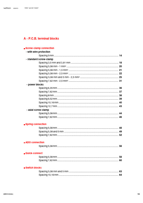
A - P.C.B. terminal blocksScrew-clamp connection- with wire protectionSpacing 5 mm (14)- standard screw-clampSpacing 3,5 mm and 3,81 mm (18)Spacing 5,08 mm - 1 mm² (20)Spacing 5,08 mm - 1,5 mm² (21)Spacing 5,08 mm - 2,5 mm² (22)Spacing 5,08 mm and 5 mm - 2,5 mm² (25)Spacing 7,62 mm - 2,5 mm² (31)- power blocksSpacing 6,35 mm (36)Spacing 7,62 mm (37)Spacing 8 mm (38)Spacing 9,52 mm (39)Spacing 10,16 mm (40)Spacing 12,7 mm (43)- axial screw-clampSpacing 5,08 mm (44)Spacing 7,62 mm (46)Spring connectionSpacing 5,08 mm (48)Spacing 5,08 and 5 mm (49)Spacing 7,62 mm (52)ADO connectionSpacing 5,08 mm (56)Quick-connectSpacing 5,08 mm (58)Spacing 7,62 mm (60)Switch blocksSpacing 5,08 mm and 5 mm (63)Spacing 10,16 mm (64)Single deck block 1 pin per pole. Vertical or horizontal mounting.Screw connection with wire protection. Without loss of spacing.Single deck block 1 pin per pole. Vertical or horizontal mounting.Screw connection with wire protection. Without loss of spacing.Single deck block 1 pin per pole. Without loss of spacing.Angled to 45VA~=ApprovalsAccessoriesType Plug-in terminal blocksScrew tightening with protection part between screw and conductorOther characteristicsCharacteristicsSolid StrandedMax. working temperature Contact resistanceSingle deck block 1 pin.Vertical mounting.Without loss of spacing.Type Type2 and3 deck blocks 1 pin per pole. Vertical mounting. Without loss of spacing.Single deck block 1 pin per pole.Block with end plate.Without loss of spacing.Type TypeSingle deck block 1 pin per pole.Block with end plate.Without loss of spacing.Type TypeType Type FC2FC2Type Type FC2FC2Single deck block 1 or 2 pins per pole. Vertical mounting. Without loss of spacing.Single deck block with heightener. Vertical mounting.Without loss of spacing.Particularly suitable when components have to be sunk into resin.Single deck block with test plug dia. 2 mm.1 or2 pins per pole. Vertical mounting. Without loss of spacing.° to Single deck block. Horizontal mountingPM 2,5/ (I)2 and3 deck single blocks.Without loss of spacing.The 2nd deck is half the spacing off-set to left.Single 2Can be assembled with the single deck vertical block (lower unit) to form several assemblies : -2nd-2nd-Not off-set.For preassembled blocks, consult us. Without loss of spacing.Type Type FC2L 106 200Type TypeFC2FC2Single deck block with test dia. 2 mm, 1 or 2 pins per pole.Vertical mounting.Without loss of spacing.Single deck block for connection at 45 P.C.B. with test dia. 2 mm.Without loss of spacing.TypeSingle deck block, 1 or 2 pins per pole. Vertical mounting.Without loss of spacing.Single deck block, 1 pin per pole.Single block with end plate.Without loss of spacing.Type TypeType Type FC21 deck2 pin blocks for 4 mmVertical mounting with permanent contact test for plug* The blocks can be clipped onto the P.C.B. to be securely held during the wave-soldering process. Positioning pins provide enhanced protection of the soldered pins against screwdriver rotation torque.Single deck block, 1 pin per pole.Single block with end plate.Without loss of spacing.Type TypeVertical mounting, 1 pin per pole.Single block with end plate.Type TypeType TypeFC2Type TypeFC2Single deck block, 1 pin per pole.Single block with end plate.Without loss of spacing.Type TypeType Type Marking using adhesive strips 1 (25)Type TypeMarking using adhesive strips 1...25Marking using adhesive strips 1 (25)Single deck blocks 2 pins per pole.Single blocks with end plate.Without loss of spacing.Type TypeMarking using adhesive strips 1 (34)Single deck blocks 2 pins per pole.Single blocks with end plate.Without loss of spacing.Type TypeMarking using adhesive strips 1...34Marking using adhesive strips 1 (34)TypeFEPLFEPLFEPLFEPLFEPLFEPLFEPLFEPLPassage for Ø 3,5 mm screwdriver to free the cable.R1 RB3A or RB5ASingle deck blocks for connection at 45 P.C.B.1 or2 pins.- 2 pins block with heightener. Particularly suitable when components have to be sunk into resin.Height 5,5 mm . 217" max.- 1-pole blocks are delivered in bulk. One end section per x-pole assembly must be ordered.Single deck blocks 2 pins with lever or with heightener + lever.Connection at 452 and3 decks blocks.Standard 2 and 3-level blocks are supplied with the pin on the 2spacing to the left in comparison with the pin on the first level.These blocks can be supplied with a greater number of poles. Consult us.Spacing 7.62 mmTypePassage for DIA. 3,5 mm screwdriver tofree the cable.RB3A or RB5ASingle deck blocks for connection at 45 P.C.B.1 or2 pins.- 2 pins block with heightener. Particularly suitable when components have to be sunk into resin.Height 5,5 mm . 217" max.- 1-pole blocks are delivered in bulk. One end section per x-pole assembly must be ordered.Single deck block 2 pins with lever or heightener + lever.Connection at 45A.D.O. the ultimate connection technologyTHE CLEVER PRODUCTIVITYComparison between different connection timesBased on 100 points :screw clamp connection with ferruleSingle-block from 2 to 24 poles without loss of spacing, ADO terminal blocks permit the connection of 2 wires of the same size and nature, up to 1 mmOUTAD1SNA 205 710 R1100 Pneumatic tool installationTechnical informationEnergy : lubricated compressed air.Air pressure : 5,5 to 8 PSI.Lubrication BY F.R.L.(Filter, Regulator, Lubricator)(1 oil drop every 20 operations)Compressed-air supply : standard pipe DIA. 4 mm.Connection of the pipe to the tool by quick releasecoupling (integrated into the tool).Type Type Type Adhesive strips 1...25Adhesive strips 1...25On requestType Type Type Adhesive strips 1...25On requestType Type TypeAdhesive strips 1...34On requestAdhesive strips 1 (34)This product is designed to be sunk intoabout 6 mm thick resin.Type Type TypeAdhesive strips 1 (34)Type Type TypeOn requestAdhesive strips 1...34Adhesive strips 1 (34)。
数据视频RMC-180控制箱快速启动指南说明书
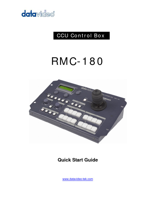
RMC-180Quick Start GuideTable of ContentsWarnings and Precautions (2)Warranty (3)Disposal (3)Packing List (4)Introduction (4)Features (4)Front Panel (5)Step by step to save camera position (7)Menu Setup (7)Rear Panel (9)Firmware upgrade procedure (10)Service & Support (12)Warnings and Precautions1. Read all of these warnings and save them for later reference.2. Follow all warnings and instructions marked on this unit.3. Unplug this unit from the wall outlet before cleaning. Do not use liquid or aerosol cleaners. Use a dampcloth for cleaning.4. Do not use this unit in or near water.5. Do not place this unit on an unstable cart, stand, or table. The unit may fall, causing serious damage.6. Slots and openings on the cabinet top, back, and bottom are provided for ventilation. To ensure safe andreliable operation of this unit, and to protect it from overheating, do not block or cover these openings. Do not place this unit on a bed, sofa, rug, or similar surface, as the ventilation openings on the bottom of the cabinet will be blocked. This unit should never be placed near or over a heat register or radiator. This unit should not be placed in a built-in installation unless proper ventilation is provided.7. This product should only be operated from the type of power source indicated on the marking label of theAC adapter. If you are not sure of the type of power available, consult your Datavideo dealer or your local power company.8. Do not allow anything to rest on the power cord. Do not locate this unit where the power cord will bewalked on, rolled over, or otherwise stressed.9. If an extension cord must be used with this unit, make sure that the total of the ampere ratings on theproducts plugged into the extension cord do not exceed the extension cord’s rating.10. Make sure that the total amperes of all the units that are plugged into a single wall outlet do not exceed15 amperes.11. Never push objects of any kind into this unit through the cabinet ventilation slots, as they may touchdangerous voltage points or short out parts that could result in risk of fire or electric shock. Never spill liquid of any kind onto or into this unit.12. Except as specifically explained elsewhere in this manual, do not attempt to service this product yourself.Opening or removing covers that are marked “Do Not Remove” may expose you to dangerous voltage points or other risks, and will void your warranty. Refer all service issues to qualified service personnel.13. Unplug this product from the wall outlet and refer to qualified service personnel under the followingconditions:a. When the power cord is damaged or frayed;b. When liquid has spilled into the unit;c. When the product has been exposed to rain or water;d. When the product does not operate normally under normal operating conditions. Adjust onlythose controls that are covered by the operating instructions in this manual; improper adjustmentof other controls may result in damage to the unit and may often require extensive work by aqualified technician to restore the unit to normal operation;e. When the product has been dropped or the cabinet has been damaged;f. When the product exhibits a distinct change in performance, indicating a need for service.WarrantyDatavideo warrants that the equipment it manufactures shall be free from defects in material and workmanship for a period of 12 months from the date of product purchased. If equipment fails due to such defects, Datavideo will, at its option, repair or provide a replacement for the defective part or product.Equipment that fails after the warranty period, has been operated or installed in a manner other than that specified by Datavideo, or has been subjected to abuse or modification, will be repaired for time and material charges at the Buyer’s expense.This warranty does not affect your statutory rights within the Country of purchase.DisposalFor EU Customers only - WEEE Marking.This symbol on the product indicates that it will not be treated as household waste. It must be handed over to the applicable take-back scheme for the recycling of electrical and electronic equipment. For more detailed information about the recycling of this product, please contact your local Datavideo office.Packing List1 x USB cable USB A-USB A L:1.8M1 x Switching adaptor DC 12V / 0.5A1 x RMC-180 Instruction ManualIntroductionThe RMC-180 is special designed for remote controlling the Panasonic PTZ Camera AW-HE100 with the video calibration functions with it. One of RMC-180 can connect up to four of AW-HE100 by RJ-45 connection and up to 1,000 Meter distant away. To combine the Datavideo HD Switcher SE-2000 will be a turn key and affordable HD multi-Camera system for the application of big conference, church and surveillance market.* RMC-180 supports 3 kinds of protocol:1. PELCO2. Panasonic AW-series protocol3. Canon BU-45 Non-proprietary protocolFeatures-Connects up to four of Panasonic PTZ camera AW-HE100-Pan-Tile-Zoom with speed control by Joystick-Remote calibrates the RB Balance, Iris, Focus, Gain, NR … and more-Presetting the PTZ and video calibration up to four camera-RS422 remote control protocol by RJ45 connector can connect camera up to 1,000 meter away.-Tally input interface is fully compatible with Datavideo tally connection standard-Small side can mount on the studio table with switcherFront Panel7.Lock 8. Speed 9. MENU 10. LCD Monitor 11. Selectors (No Function) 12. Mode Select 1. Focus 2. STR 3. CH A~D (Group Select) 4. IRIS5. Ch A~D (Channel Select)6. Controller1 4 6235 7 9 8 10FOCUSControls camera focus is controlled by the rotary knob.# When the MANUAL switch LED light on, the camera focus is by manual setting.STRSTR switch is save the camera position.Channel group A, B, C, DChannel switch is select the save group CH A~CH D.IRISControls camera IRIS is controlled by the rotary knob.# When the MANUAL switch LED light on, the camera IRIS is by manual setting.Channel ButtonsChannel buttons is save the camera position.# See page.7 for more details.ControlThe joystick is used in conjunction with several features. It is used to adjust the PAN, TILT, ZOOM settings of the video camera.# When the LOCK switch LED light on, the joystick function disable.SpeedThree different modes for joystick control speed.MenuMenu button is setting the RMC-180 functions configuration.LCD DisplayThe status of the RMC-180 is displayed within the LCD Display.Mode SelectMODE – Color barA,B – Save MODE A or MODE BATW – Automatically white balanceStep by step to save camera position1. Select group on CH A or CH B or CH C or CH D.2. Push STR button, at same time you selected group will light on.3. Push 1 of 4 light on button to save the camera position.Menu Setup1. POWER CONTROLControl camera power ON / OFF.3. WHITE BALANCE STRSave white balance status of mode A or mode B.(Please selected mode A or mode B before you into this setting)7. SHUTTER SETSetting camera shutter mode8. VOUT FORMAT SELECTSetting video output format9. PAN DIRECTION SETSetting the camera pan direction control is normal or reversed (LEFT / RIGHT).10. TILT DIRECTION SETSetting the camera tilt direction control is normal or reversed (UP / DOWN).11. ZOOM DIRECTIONSetting the camera zoom direction control is normal or reversed (ZOOM IN / ZOOM OUT).Turn the joystick left or right is control camera zoom in or zoom out.12. FOCUS DIRECTION SETSetting the camera focus direction control is normal or reversed (LEFT / RIGHT).FOCUS setting has 4 kinds speed let you select:Step 1 - Push button, at same time the button LED will light on.Step 2 - Push button, the button will twinkling.Step 3 - Push button select FOCUS control speed.Step 4 - Push and turn button control the camera focus.13. IRIS DIRECTION SETSetting the camera direction control is normal or reversed (LEFT / RIGHT).IRIS setting has 4 kinds speed let you select:Step 1 - Push button, at same time the button LED will light on.Step 2 - Push button, the button will twinkling.Step 3 - Push button select IRIS control speed.Step 4 - Push and turn button control the camera iris.14. JOYSTICK SENSITIVITYSetting the joystick controls sensitivity.18. RMC-180 FW VERSIONDisplay the RMC-180 firmware version.19. AW-HE100 FW VERSIONDisplay the AW-HE100 firmware version.20. EXITExit the set up menu mode.Rear PanelFirmware UpgradeUSB connect to computer for firmware upgrade.Camera connect (RJ-45)4 RJ-45 ports connect to camera.Tally InputSend in red color tally signal to tally LED. Red means on-air.DC In SocketConnect the supplied 12V 0.5A PSU to this socket. The connection can be secured by screwing the outer fastening ring of the DC In plug to thesocket.Power On/Off SwitchSwitches the power On / Off 1. Firmware Upgrade 2. RJ-45 Connect (To Camera) 3. Tally Input 4. Power input 12V 0.5A 5. Power On / Off switch 1 2 3 45Firmware upgrade procedure1. Power on RMC-180, and then connect USB port to computer.2. Push (FOCUS AUTO / MANUAL, IRIS AUTO / MANUAL, CHA-1, CHC-4 KEY ) at same time.3. Reset RMC-180 Power.4. RMC-180 LCD will display as below:5. “RMC-180_U38 “will display on the computer monitor.6. Into the ”RMC-180_U38”, and then delete ” bootcode.bin”file.7. Paste “RMC180_PCBB_0v1c.bin” on the same place. 8. Reset Power, the RMC-180 LCD will display as below:Service & SupportIt is our goal to make your products ownership a satisfying experience. Our supporting staff is available to assist you in setting up and operating your system. Please refer to our web site for answers to common questions, support requests or contact your local office below.Datavideo Global Website: Datavideo CorporationTel: +1 562 696 2324 Fax: +1 562-698-6930 E-Mail:********************** Datavideo Technologies Europe BVTel: +31-30-261-96-56 Fax: +31-30 261-96-57 E-Mail:******************** Datavideo UK LimitedTel: +44 1457 851 000 Fax: +44 1457 850 964 E-Mail:******************.uk Datavideo Technologies Co., LtdTel: +886 2 8227 2888 Fax: +886-2-8227-2777 E-mail:*********************.tw Datavideo Technologies China Co., LtdTel: +86 21-5603 6599 Fax:+86 21-5603 6770 E-mail:******************** Datavideo Technologies (S) PTE LTDTel: +65-6749 6866 Fax: +65-6749 3266 E-mail:******************** Datavideo HK LtdTel: +852 2833 1981 Fax: +852-2833-9916 E-mail:******************.hkAll the trademarks are the properties of their respective owners.Datavideo Technologies Co., Ltd. All rights reserved 2018G082060542B1。
JHS-180AIS中文操作说明书

自动识别系统JHS-180 中文操作说明书目录1 1.1 1.22 2.1 2.1.1 2.1.2 2.2 2.2.1 2.3 2.3.1 2.3.23 3.1 3.1.1 3.1.2 3.1.3 3.1.4 3.1.5 3.2 3.2.1 3.2.2 3.2.3 3.2.4 3.3 3.3.1 3.3.2 3.3.3 3.3.4 部件名称和功能--------------------------------------------------------------------操作面板-----------------------------------------------------------------------------显示-----------------------------------------------------------------------------------基本操作-------------------------------------------------------------------------------开电源----------------------------------------------------------------------------------他船清单-------------------------------------------------------------------------------他船详细清单-------------------------------------------------------------------------关电源----------------------------------------------------------------------------------关显示----------------------------------------------------------------------------------报警-------------------------------------------------------------------------------------警戒区报警----------------------------------------------------------------------------消失目标警报-------------------------------------------------------------------------主菜单----------------------------------------------------------------------------------信息菜单-------------------------------------------------------------------------------编辑与发射----------------------------------------------------------------------------发射屏----------------------------------------------------------------------------------接收屏----------------------------------------------------------------------------------查询-------------------------------------------------------------------------------------长度范围信息-------------------------------------------------------------------------目的地设置----------------------------------------------------------------------------目的地----------------------------------------------------------------------------------航点-------------------------------------------------------------------------------------估计到达时间-------------------------------------------------------------------------航点-------------------------------------------------------------------------------------航行信息设置-------------------------------------------------------------------------航行状况信息-------------------------------------------------------------------------在船人员-------------------------------------------------------------------------------船舶和货物类型----------------------------------------------------------------------吃水深度-------------------------------------------------------------------------------11222233444455589911121213141415161616173.3.5 3.4 3.4.1 3.4.2 3.5 3.5.1 3.5.2 3.6 3.6.1 3.6.2 3.6.3 3.6.4 3.6.5 3.6.6 3.7 3.7.1 3.7.2 3.7.3 3.7.4 3.7.5 3.7.6 龙骨以上高度------------------------------------------------------------------------报警设置-------------------------------------------------------------------------------距离-------------------------------------------------------------------------------------消失物标------------------------------------------------------------------------------船队设置-------------------------------------------------------------------------------船名------------------------------------------------------------------------------------- MMSI(船舶移动识别码)-----------------------------------------------------------设置菜单-------------------------------------------------------------------------------密码设置-------------------------------------------------------------------------------信道处理设置-------------------------------------------------------------------------本船数据显示设置-------------------------------------------------------------------长距离应答设置----------------------------------------------------------------------对比度设置----------------------------------------------------------------------------重发号码设置-------------------------------------------------------------------------维护菜单-------------------------------------------------------------------------------收发状况对数显示-------------------------------------------------------------------自动识别系统报警显示-------------------------------------------------------------传感器状况显示----------------------------------------------------------------------电源开/关对数显示-------------------------------------------------------------------发射关对数显示----------------------------------------------------------------------软件版本显示-------------------------------------------------------------------------1718181818191920202123242425252526262728281.部件名称与功能1.1 操作面板(1)LCD面板更多信息参考“1.2显示”。
CP-180控制盘 说明书

CP-180使用说明书目 录1. 控制盘的安装 (1)2. 电源线的连接 (1)3. 各部的说明 (2)4. 机头的设定方法 (2)5. 机头调整(仅限直接马达方式的缝纫机) (3)6. 操作盘的说明 (4)7. 各种缝制图案的操作方法 (5)8. 关于简单操作设定 (9)9. 关于生产支援功能 (9)10. 底线计数器的使用方法 (12)11. 切线计数器的使用方法 (13)12. 关于半针补正开关 (13)13. 关于钥匙锁定功能 (14)14. 关于布边传感器ON/OFF开关 (14)15. 关于自动切线开关 (14)16. 关于单触发自动缝制开关 (14)17. 关于禁止切线开关 (15)18. 关于功能设定开关 (15)19. 关于选购项目输入输出设定 (16)20. 踏板传感器中立自动补正 (18)21. 自动压脚提升功能的选择方法 (18)22. 功能设定数据的初期化方法 (19)23. 异常代码的确认方法 (19)注意1) 从窗板上卸下窗板固定螺丝1。
2) 请使用控制盘附属螺丝5、平垫片3以及橡胶座4把控制盘2安装到机头上。
1. 控制盘的安装<机头部和支架安装孔位置>注意使用机器之前请阅读控制箱使用说明书中的「有关安全的注意事项」,充分了解内容之后再使用机器。
另外,因为本产品是精密机器,使用时请充分注意不要弄上水或油,也不要给与掉落等冲击。
安装孔螺丝DDL-9000A 1 - 5M5×12控制盘附属螺丝DDL-9000B 1 - 5(安装AK)M5×14窗板螺丝(没有安装AK)M5×12控制盘附属螺丝LH-3500A2 - 5M5×14窗板螺丝12表11234561) 把控制盘的电源线1穿过机台孔A ,再穿过机台下面。
2) 连接连接器时,请参照控制箱的使用说明书。
2. 电源线的连接1A124531电源指示LED :打开电源开关(ON)后亮灯。
赛恩瑞德C-180T及C-180E线号机快速使用说明

赛恩瑞德线号机快速使用指南
注意:1.请在安装耗材前确定电源处于断开状态
2.使用完毕后请先断开电源然后再拆除耗材分别存放!
1.套管的安装流程:首先确定电源处于断开状态,以及胶辊儿旋钮处于放松状态,下
面【图④】中的不规则多边形线框的范围就是套管所要安放的范围。
将套管安放在上【图④】的套管安放位置范围内,安放后效果如下【图⑥】套管安放好后,将胶辊旋钮向顺时针方向旋转,是胶辊压紧套管,效果如下【图⑥】。
顺时针旋
动“旋钮”
如上【图⑥】的状态为套管耗材安放完毕后盖上上盖,可以打开电源输入打印的信息进行打印的状态。
2.贴纸盒的安装流程:首先确定电源处于断开状态,以及胶辊儿旋钮处于放松状态,如【图①】:注意:打印贴纸前,确保贴纸前段超过全切刀
如上【图①】,此时胶辊旋钮是处于松弛状态,下面将放入贴纸盒。
将胶辊旋钮按照黑色弧形箭头所标方向,顺时针旋转使胶辊压紧贴纸,如下【图③】。
顺时针旋动“旋钮”
如上【图③】的状态为套管耗材安放完毕后盖上上盖,可以打开电源输入打印的信息进行打印的状态。
- 1、下载文档前请自行甄别文档内容的完整性,平台不提供额外的编辑、内容补充、找答案等附加服务。
- 2、"仅部分预览"的文档,不可在线预览部分如存在完整性等问题,可反馈申请退款(可完整预览的文档不适用该条件!)。
- 3、如文档侵犯您的权益,请联系客服反馈,我们会尽快为您处理(人工客服工作时间:9:00-18:30)。
E C S-180使用说明书V1.0121114-CAL-FENGHAI-(2020YEAR-YICAI)_JINGBIANECS-180温度控制器使用说明书1.产品概述Serial code继电器传感器蜂鸣音断电检测制冷除霜风机灯光/外部报警调温除霜/S2 冷凝/S3门开关/S4B VA(30.05.05.00)S234.B 30 5/●5/●×√●●●●×A(05.10.10.05)S234.B.V 5 10/●10/●5/●√●●●●●注:●表示可选配,×表示无此配置,√表示固定配置,数字表示继电器触点容量;示例说明:30表示继电器触点容量为30A,5/●表示继电器触点容量为5A,且该继电器可选配。
1.2 产品应用概述●ECS-180温度控制器可用于中低温药品柜、厨房柜、超市分体柜、风幕柜、岛柜、便利柜、酒柜等。
●该产品功能采用积木式设计,可根据实际需求选配除霜、风机、灯光/外部报警控制。
●可选配蒸发器传感器、冷凝器传感器、门开关、蜂鸣器、断电检测功能。
●制冷继电器最大可达到30A/240VAC输出,可直接驱动单相1.5HP压缩机。
●彩色数码显示,工作状态符号显示,温度显示分辨率0.1,前面板防水等级IP65。
●控制器具备温度传感器自检功能,检测到系统故障时具有多种保护和报警方式。
●特设一键还原功能,快速连接式端子,方便专业设备制造商的生产和售后。
●可转换摄氏、华氏温度测量单位。
●具备同步除霜开关信号检测功能,可组成实时时钟定时同步除霜网络。
●柜内温度超限报警具备绝对值和相对值两种模式。
●灯光/外部报警继电器可使用软件选择,当选择外部报警继电器功能时则可连接远程警铃。
●控制器选配安装备用电源接入部件后可实现控制器断电检测和报警。
●具备完整的热气除霜卸压启动控制逻辑,防止带压启动,从而延长压缩机的寿命。
2.操作及显示面板3.规格尺寸安装尺寸:71mm×29mm 整机尺寸:78.5mm×34.5mm×82mm4.技术参数1)测量范围:-50℃~90℃或 -58℉~194℉(仅当传感器校正值设置为0时)2)温度分辨率:0.1℃或 1℉3)测温精度:-40℃~50℃时±1℃, 51℃~70℃时±2℃,其它±3℃或 -40℉~122℉时±2℉,123℉~158℉时±4℉,其它±6℉4)控温范围:-50℃~85℃或 -58℉~185℉5)电源电压: 220VAC±10% 50/60Hz6)整机功耗:<3W7)外部备用电源电压:7.0VDC~13.5VDC8)输入端口:柜温传感器、蒸发器传感器、冷凝器传感器、门开关(门打开时,传感器输出常开信号)9)输出端口容量:Serial code A(30.05.05.00)S234.B A(05.10.10.05)S234.B .V制冷30A/240VAC,可直接驱动单相1.5HP压缩机5A/250VAC,化霜5A/250VAC 10A/250VAC 风机5A/250VAC 5A/250VAC灯光/外部报警无10A/250VAC10)前面板防护等级:IP6511)工作环境温度:0℃~55℃12)存储温度:-25℃~75℃13)相对湿度:20%~85%(无结露)5.指示灯状态说明指示灯符号状态表示意义设置指示灯set 亮参数设置灭测控状态制冷指示灯亮制冷工作灭制冷停止闪烁制冷延时除霜指示灯亮除霜工作灭除霜停止风机指示灯亮风机启动灭风机关闭除霜滴水指示灯drip 亮除霜滴水启动灭除霜滴水结束门信号指示灯亮门开关打开灭门开关关闭断电指示灯亮控制器断电6.菜单菜单描述设定范围默认℃/℉H1 H7用户菜单St 温度设置值温度设置下限~温度设置上限4℃40℉℃/℉Po 管理者菜单密码00~99(密码为55且不可更改)00 /管理者菜单C1 控制回差0.5℃~9.0℃ 4.0℃8℉℃/℉A3 比例制冷开启时间1~60 30 30 minA4 蜂鸣音输出总开关0:禁止蜂鸣音输出1:允许蜂鸣音输出1 1 /A5 柜温超下限报警值-50℃~柜温超上限报警值-10℃14℉℃/℉-58℉~柜温超上限报警值A6 柜温超上限报警值柜温超下限报警值~85℃24℃75℉℃/℉柜温超下限报警值~185℉A7 柜温超温报警延时0~60 20 20 3min A8 通电首次柜温超温报警延时0~60 40 40 3minA9 超温报警上偏差1℃~30℃10℃20℉℃/℉1℉~60℉A10 超温报警下偏差1℃~30℃5℃10℉℃/℉1℉~60℉A11 超温报警模式0:绝对温度点1:设定值+超温报警偏差0 0 /A12 灯光/报警继电器选择0:灯光输出1:报警输出0 0 /do1 门开关控制输出0:取消门开关1:门打开时关闭风机2:门打开时打开灯光,门关闭时关闭灯光3:门打开时关闭风机、打开灯光,门关闭时关闭灯光4:门打开时作为同步除霜信号输入,启动除霜0 0 /do2 门打开时是否需要蜂鸣器响应0:无需1:需要0 0 /cd1 冷凝器传感器选择0:禁用1:启用1 1 /cd2 冷凝器高温报警启动值30℃~90℃55℃131℉℃/℉86℉~194℉cd3 冷凝器高温报警下回差1℃~15℃5℃10℉℃/℉2℉~30℉隐藏菜单华氏/摄氏选择(注②)华氏摄氏摄氏华氏/注①:仅在柜温传感器正常时有效。
注②:摄氏/华氏转换后需用户自行调整其它相关参数项的数值以保证正确的参数配置,只能通过一键还原操作切换摄氏/华氏。
7. 按键功能7.1按键名称作用Set 进入参数设置状态切换菜单和参数调整菜单及参数开启/关闭灯光(仅对具备灯光控制器的型号有效) 查看冷凝器传感器温度值调整菜单及参数持续10秒执行参数一键还原查看蒸发器传感器温度值退出参数设置状态退出一键还原状态持续3秒则在制冷、除霜/除霜延迟、除霜滴水之间强制切换7.2按键操作1)参数调整测控状态下按Set键3秒后,进入用户菜单,显示St ,再次按下Set键后显示St的参数值,此时可通过操作或键修改温度设置值。
在显示St 时,按下键后,显示Po,按下Set键后显示00,此时可通过或键输入控制器管理者菜单密码。
输入控制器管理者菜单密码后按下Set键(确认密码输入完毕),显示Po。
控制器自动验证密码正确性,当密码验证通过时(进入到管理者菜单),可通过或键选择St、Po、C1、C2……Cd3参数项(即用户菜单和管理者菜单的任意参数项);否则,控制器仅停留在St 和Po参数项,不能显示其它参数项。
选定菜单项后按Set键进入当前菜单项参数值设置,按或键调整参数值,再按Set键返回菜单选择。
在任意参数设置状态下,按键或30秒无按键操作则退出参数设置并自动保存当前参数值。
注:管理者菜单密码输入单次有效,按键退出参数设置后,下次调整必须再次输入正确的密码。
2)温度查看测控状态下,按键后可查看当前蒸发器传感器温度测量值(蒸发器传感器启用且正常)按键可查看当前冷凝器传感器温度测量值(冷凝器传感器启用且正常)。
3)手动强制操作测控状态下,按键持续3秒后,可在制冷、除霜/除霜延迟、除霜滴水之间强制切换。
按键开启或关闭灯光(仅在灯光/报警继电器作为灯光使用且灯光控制与门开关无联动时有效)4)参数还原测控状态下,按键10S后,控制器显示“H0”,进入一键还原操作。
可继续按键选择恢复的参数目录项,选择范围H0~H7,按键则执行参数还原判断并退出,30S内不执行还原确认则控制器自动退出该模式且不作参数恢复注:此操作过程中需保证控制器电源稳定,操作中若发生电源异常,则需在控制器稳定上电后再次执行一次该操作。
H0 放弃参数恢复,各项参数无变化,不显示恢复成功dr代码H1 恢复H1参数值,恢复成功显示drH2 恢复H2参数值,恢复成功显示drH3 恢复H3参数值,恢复成功显示drH4 恢复H4参数值,恢复成功显示drH5 恢复H5参数值,恢复成功显示drH6 恢复H6参数值,恢复成功显示drH7 恢复H7参数值,恢复成功显示dr,摄氏转换成华氏注:转换后需用户自行调整其它相关参数数值以保证正确的参数配置8.控制输出8.1制冷:正常情况下:柜温高于温度设置值(St)+ 控制回差(C1),且压缩机启动最小间隔时间运行完后制冷输出;当柜温低于温度设置值(St),且连续制冷开启时间大于C8设定值时,制冷关闭。
柜温在温度设置值(St)和温度设置值(St) + 控制回差(C1)之间时,若制冷关闭,则压缩机启动最小间隔时间运行完和压机启动最小间隔时间完成后最大待机时间(C7)运行完后,制冷输出。
注:压缩机启动最小间隔时间在控制器通电后第一次按压缩机首次启动最小间隔时间(C3)计算,以后按压缩机开机启动最小间隔时间(C2)计算。
柜温传感器故障情况下:A1 = 0 ,取消比例开停时,制冷关闭;A1 = 1 ,启动比例开停时,制冷按设定的比例制冷开启时间(A3)和比例制冷停止时间(A2)进行周期运转。
8.2除霜:1)d4 = 0时,禁止除霜。
2)d4不为0,非除霜和非除霜滴水状态下:①蒸发器传感器启用(d1 = 1),蒸发器传感器温度大于除霜终止温度(d7)时,无法启动除霜;②蒸发器传感器启用(d1 = 1)且蒸发器传感器温度小于除霜终止温度(d7)或者蒸发器传感器禁用(d1 = 0)时(以下任一条件均可启动除霜):a、当除霜周期(d4)运行完时,启动除霜;注:除霜周期按照选择的自然时间(d3 = 1)或者累计制冷时间(d3 = 0)计算;b、持续按键3秒,启动除霜;c、当门开关作为外部同步除霜信号输入接口(d01 = 4)时,门打开即外部同步除霜信号输入时,启动除霜;注:除霜启动后延时输出时间(d10)运行完后,除霜输出。
3)除霜状态下(以下任一条件均可关闭除霜):①蒸发器传感器启用(d1 = 1),蒸发器传感器温度大于除霜终止温度(d7)时,关闭除霜;②除霜最长时间(d6)运行完,关闭除霜;③持续按键3秒,关闭除霜;4)除霜后进入除霜滴水状态,除霜后滴水时间(d8)内禁止制冷输出,在此期间排出除霜时产生的滴水;除霜后滴水时间运行完后进入制冷循环状态。
注:除霜过程显示:d5 = 0:除霜过程显示柜内实际温度;d5 = 1:除霜及除霜后柜温延时(d9)时间内显示dEF,延时(d9)运行完后显示柜内实际温度;d5 = 2:除霜和除霜滴水时间内显示dEF;d5 = 3:除霜和除霜滴水时锁定显示除霜启动时柜温。
除霜方式:d11 = 0:电热除霜;d11 = 1:热气除霜。
8.3风机:风机运行模式:F1 = 0:风机随制冷循环状态同启同停;F1 = 1:风机持续运行,除霜时关闭;F1 = 2:风机持续运行,除霜和滴水时关闭;F1 = 3:风机持续运行,除霜时关闭,除霜结束后运行完除霜后风机启动延时(F3)开启;当门开关控制输出参数选择1或者3时,当柜门打开后风机关闭,柜门关闭后风机恢复柜门打开前的工作状态。
