L7815CD2T中文资料
L7824CD2T中文资料
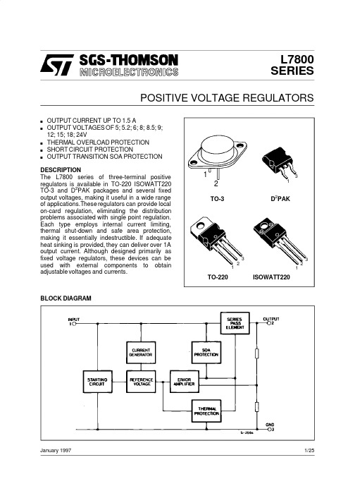
TO-3
L7805T L7805CT L7852CT L7806T L7806CT L7808T L7808CT L7885CT L7809CT L7812T L7812CT L7815T L7815CT L7818T L7818CT L7820T L7820CT L7824T L7824CT
TO-3
65
2
2.5
Ro Output Resistance Isc Short Circuit Current Is cp Short Circuit Peak Current
f = 1 KHz
Vi = 35 V Tj = 25 oC
Tj = 25 oC
19
0.75 1.2
1.3
2.2
3.3
Unit V V
Io Output Current
Ptot Power Dissipation
To p Operating Junction Temperature Range (for L7800) (for L7800C)
Tstg Storage Temperature Range
Value
Unit
35
V
40
V
Io = 5 mA to 1 A Po ≤ 15 W Vi = 8 to 20 V Vi = 7 to 25 V Tj = 25 oC Vi = 8 to 12 V Tj = 25 oC
Io = 5 to 1500 mA Tj = 25 oC Io = 250 to 750 mA Tj = 25 oC
Tj = 25 oC
4.65
5
5.35
3
50
1
25
100 25
三端稳压集成电路(介绍)
一、简介常见的三端固定集成稳压电路有正电压输出的78××系列和负电压输出的79××系列。
所谓三端就是该集成稳压电路的引出脚只有三条,即:输入端、输出端和接地端;其封装形式采用晶体三极管的标准封装,外形与晶体三极管一样。
因此,用它来组成稳压电源需要的外围元件很少,电路非常简单。
该集成稳压电路内部还设置了过流、芯片过热及调整管安全工作区的保护电路,使用起来安全、可靠。
该系列集成稳压电路型号中的78或79后面的数字代表该三端集成稳压电路的输出电压数值,以伏特(V)为单位。
例如7806表示输出电压为正6V;7924表示输出电压为负24V。
此外,我们还可以发现在数字78××或79××的前面和后面还有一些英文字母,如LM78××、CW78××C、TA78××AP等。
前面的字母称为“前缀”,通常为生产厂家(公司)的代号,如“TA”表示日本东芝公司的产品。
后面的字母称为“后缀”,用来表示输出电压容差和封装形式等。
通常不同生产厂家(公司)对三端集成稳压电路型号后缀所用字母的含义和定义各不相同。
不过,这对我们实际使用影响不大。
78××系列集成稳压电路的输出电压大致有8种(输出电压的种类随厂商的不同而异): 7805、78 06、7809、7810、7812、7815、7818、7824。
按其最大输出电流又可分为78××、78M××、78××三个分系列。
其中78L××系列的最大输出电流为100mA;78M××系列最大输出电流为500mA;78××系列最大输出电流为1.5A。
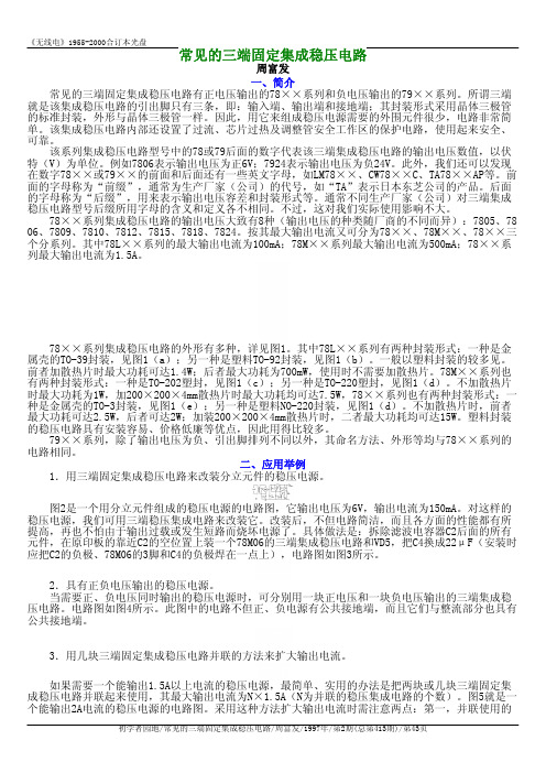
78××系列集成稳压电路的外形有多种,详见图1。
其中78L××系列有两种封装形式:一种是金属壳的TO-39封装,见图1(a);另一种是塑料TO-92封装,见图1(b)。
L7818C中文资料
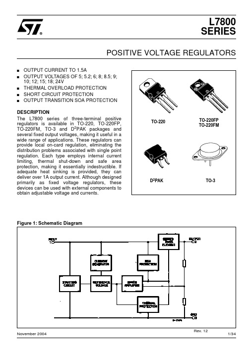
Figure 2: Schematic Diagram
2/34
L7800 SERIES
Figure 3: Connection Diagram (top view)
TO-220 (Any Type)
TO-220FP/TO-220FM
D2PAK (Any Type)
TO-3
Table 3: Order Codes
TO-220
TO-220FP TO-220FM
D2PAK
TO-3
Figure 1: Schematic Diagram
November 2004
Rev. 12
1/34
L7800 SERIES
Table 1: Absolute Maximum Ratings
Symbol VI IO Ptot Tstg Top DC Input Voltage Output Current Power Dissipation Storage Temperature Range Operating Junction Temperature for L7800 Range for L7800C Parameter for VO= 5 to 18V for VO= 20, 24V Value 35 40 Internally Limited Internally Limited -65 to 150 -55 to 150 0 to 150 °C °C Unit V
TYPE L7805 L7805C L7852C L7806 L7806C L7808 L7808C L7885C L7809C L7810C L7812 L7812C L7815 L7815C L7818 L7818C L7820 L7820C L7824 L7824C TO-220 (A Type) TO-220 (C Type) TO-220 (E Type) D2PAK (A Type) (*) D2PAK (C Type) (T & R) TO-220FP TO-220FM TO-3 L7805T L7805CT L7852CT L7806T L7806CT L7808T L7808CT L7885CT L7809CT L7812T L7812CT L7815T L7815CT L7818T L7818CT L7820T L7820CT L7824T L7824CT
78L05中文资料

TO-92 SOT-891. VOUT2. GND3. GND4. NC5. NC6. GND7. GND8.VINSOP-8CYT78L05GND10uF 10uF最大的额定值:参数符号 额定值 单位功耗 P 0.75 W 输入电压 V IN 18V 封装热阻抗 ӨJA 150(TO-92) ℃/W 烙铁焊接温度 (10秒) T LEAD 260℃ 工作温度范围 T J 0 to +125 ℃ 存储温度 T STG-65 to +150℃静电防护V ESD 2.7KV电性能参数:VIN = 10V; IOUT = 10mA; CIN = 0.33µF; COUT = 0.1µF TJ = 25°C; 有特殊说明的除外。
符号参数测试条件最小值典型值最大值单位V OUT 输出电压4.8 55.2 V△V OUT /V OUT 空载调整率 7V ≤ V IN ≤ 18V -- 11 45 △V OUT /V OUT负载调整率(5) 1mA ≤ I OUT ≤ 100mA -- 5 50 mVI Q 静态电流 -- 4.3 68V ≤ V IN ≤ 18V -- 1.1 -- △I Q 静态电流调整率 1mA ≤ I OUT ≤ 40mA--0.13--mA△V IN /V OUT输出纹波抑制 F=120Hz , 8V ≤ V IN ≤16V -- 62 -- dB I PK 最大输出电流 -- 150 -- mA△V OUT /△T 输出电压温度系数 I OUT =5mA --0.66 -- MV/℃V IN (Min) 空载最小输入电压-- 6.1 6.4 V静态电流与输入电压静态电流嗻mA 嗼输入电压(V ) 结温(℃) 静态电流嗻mA 嗼静态电流与结温压差与结温压差嗻V 嗼结温(℃) 压差:△V OUT =2%压差与输出电流压差嗻V 嗼输出电流(mA )纹波抑制纹波抑制嗻dB 嗼封装尺寸图: TO-92封装尺寸图: SOP-8尺寸英制(in ) 公制(mm) 编号 最小 最大最小 最大A 0.175 0.205 4.445 5.207B 0.170 0.210 4.318 5.334 E 0.500 0.610 12.70 15.50 F 0.016 0.021 0.407 0.533 G 0.045 0.055 1.143 1.397 H 0.095 0.105 2.413 2.667 J 0.080 0.105 2.032 2.667 K0.125 0.165 3.175 4.191尺寸英制(in ) 公制(mm) 编号 最小 最大最小 最大A 0.05320.0688 0.35 1.75 A1 0.00400.0098 0.10 0.25B 0.01300.0200 0.33 0.51 B1 0.050BSC 1.27BSCC 0.00750.0098 0.19 0.25D 0.18900.1968 4.80 5.00 H 0.22840.2440 5.80 6.20 E0.14970.1574 3.80 4.00封装尺寸图: SOT-89英制(in)公制(mm)编号最小最大最小最大A 0.173 0.181 4.400 4.600B 0.159 0.167 4.050 4.250C 0.067 0.075 1.700 1.900D 0.051 0.059 1.300 1.500E 0.094 0.102 2.400 2.600F 0.035 0.047 0.890 1.200G 0.118REF 3.00REFH 0.059REF 1.50REFI 0.016 0.020 0.400 0.520J 0.055 0.063 1.400 1.600K 0.014 0.016 0.350 0.410L 10°TYP 10°TYPM 0.028REF 0.70REF。
L7815CD2T-TR中文资料

L7805CP L7852CP L7806CP L7808CP L7885CP L7809CP L7810CP L7812CP L7815CP L7818CP L7820CP L7824CP
L7805CF L7852CF L7806CF L7ห้องสมุดไป่ตู้08CF L7885CF L7809CF
L7812C-V L7815C-V
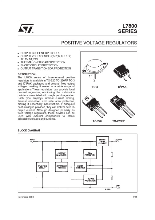
L7800 SERIES
POSITIVE VOLTAGE REGULATORS
s s
s s s
OUTPUT CURRENT TO 1.5A OUTPUT VOLTAGES OF 5; 5.2; 6; 8; 8.5; 9; 10; 12; 15; 18; 24V THERMAL OVERLOAD PROTECTION SHORT CIRCUIT PROTECTION OUTPUT TRANSITION SOA PROTECTION
5/34
L7800 SERIES
Table 5: Electrical Characteristics Of L7806 (refer to the test circuits, TJ = -55 to 150°C, VI = 11V, IO = 500 mA, CI = 0.33 µF, CO = 0.1 µF unless otherwise specified).
Symbol Parameter D2PAK 3 62.5 TO-220 5 50 TO-220FP TO-220FM 5 60 5 60 TO-3 4 35 Unit °C/W °C/W
Rthj-case Thermal Resistance Junction-case Max Thermal Resistance Junction-ambient Rthj-amb Max
稳压管大全)
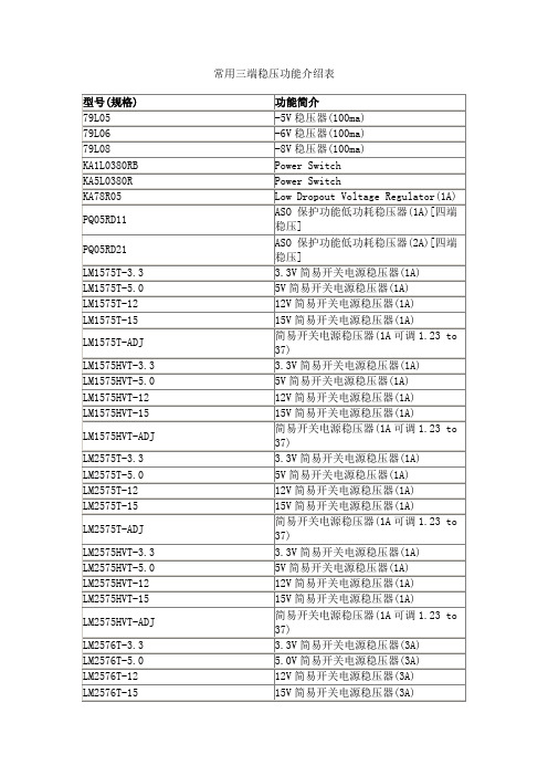
3.3V简易开关电源稳压器(1A)
LM1575T-5.0
5V简易开关电源稳压器(1A)
LM1575T-12
12V简易开关电源稳压器(1A)
LM1575T-15
15V简易开关电源稳压器(1A)
LM1575T-ADJ
简易开关电源稳压器(1A可调1.23 to 37)
LM1575HVT-3.3
LM2575HVT-ADJ
简易开关电源稳压器(1A可调1.23 to 37)
LM2576T-3.3
3.3V简易开关电源稳压器(3A)
LM2576T-5.0
5.0V简易开关电源稳压器(3A)
LM2576T-12
12V简易开关电源稳压器(3A)
LM2576T-15
15V简易开关电源稳压器(3A)
LM2576T-ADJ
79L08
-8V稳压器(100ma)
KA1L0380RB
Power Switch
KA5L0380R
Power Switch
KA78R05
Low Dropout Voltage Regulator(1A)
PQ05RD11
ASO保护功能低功耗稳压器(1A)[四端稳压]
PQ05RD21
ASO保护功能低功耗稳压器(2A)[四端稳压]
型号(规格)
功能简介
兼容型号
CA3130
高输入阻抗运算放大器
Intersil[DATA]
CA3140
高输入阻抗运算放大器
CD4573
四可编程运算放大器
MC14573
ICL7650
斩波稳零放大器
LF347(NS[DATA])
带宽四运算放大器
LM7815ACT中文资料
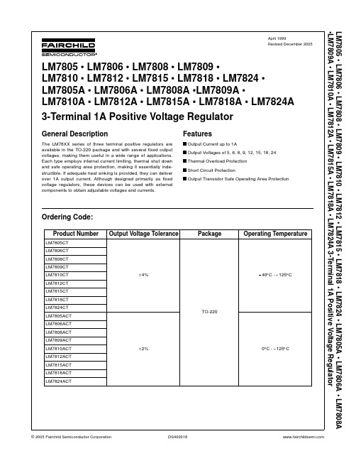
Ordering Code:
Product Number
LM7805CT LM7806CT LM7808CT LM7809CT LM7810CT LM7812CT LM7815CT LM7818CT LM7824CT LM7805ACT LM7806ACT LM7808ACT LM7809ACT LM7810ACT LM7812ACT LM7815ACT LM7818ACT LM7824ACT
Features O Output Current up to 1A O Output Voltages of 5, 6, 8, 9, 12, 15, 18, 24 O Thermal Overload Protection O Short Circuit Protection O Output Transistor Safe Operating Area Protection
Parameter
Symbol
Conditions
Min
Typ
Max
Unit
Output Voltage
VO
TJ = 25qC
5mA d IO d 1A, PO d 15W, VI = 8.0V to 21V
5.75
6.0
6.25
V
5.7
6.0
6.3
Line Regulation (Note 4)
元器件交易网
Electrical Characteristics (LM7806)
(Refer to the test circuits. 40qC TJ 125qC, IO = 500mA, VI = 11V, CI = 0.33PF, CO = 0.1PF, unless otherwise specified)
7815芯片应用手册
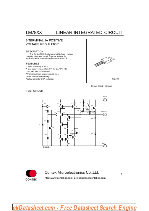
LINEAR INTEGRATED CIRCUIT
SYMBOL
ISC Vd
TEST CONDITIONS
VI=35V, Tj=25 C Tj=25 C
MIN
TYP
250 2.0
MAX
UNIT
mA V
Contek LM7808 ELECTRICAL CHARACTERISTICS
PARAMETER
Output Voltage Load Regulation Line regulation Quiescent Current Quiescent Current Change Output Noise Voltage Temperature coefficient of Ripple Rejection Peak Output Current Short-Circuit Current Dropout Voltage
MIN
4.8 4.75
TYP
5.0
MAX
5.2 5.25 50 25 50 50 8.0 1.0 0.5
标准线性电源之常用芯片
标准线性电源之常用芯片TI 德州仪器固定输出稳压器,可调分流电压稳压器 ,可调稳压器1.固定输出稳压器(标准线性电源)2.MC79L05ACLPR:小电流负电压稳压器3.MC79L12ACLP:小电流负电压稳压器4.MC79L15ACLP:小电流负电压稳压器5.TL780-05KCS:5V,1.5A稳压器6.TL780-12KCS:12V,1.5A稳压器7.TL780-15KCS:15V,1.5A稳压器8.UA7805CKC:5V通用大电流正电压稳压器9.UA7810CKC:10V通用大电流正电压稳压器10.UA7812CKC:12V通用大电流正电压稳压器11.UA7815CKC:15V通用大电流正电压稳压器12.UA78L02ACLP:2V用小电流正电压稳压器13.UA78L05ACD:5V,100mA电压稳压器14.UA78L05ACLP:5V通用小电流正电压稳压器15.UA78L05ACPK:5V,100mA电压稳压器16.UA78L05CLP:通用低电流正电压稳压器17.UA78L06ACLP:6V通用小电流正电压稳压器18.UA78L08ACLP:8V通用小电流正电压稳压器19.UA78L09ACLP:9V通用小电流正电压稳压器20.UA78L09CLP:9V通用小电流正电压稳压器21.UA78L12ACPK:12V,100mA电压稳压器22.UA78L15ACLP:15V通用小电流正电压稳压器23.UA78M05IDCY:5V,500mA固定输出电压稳压器24.可调分流电压稳压器(标准线性电源)25.TL431ACDBVR:3端可调精密分流稳压器26.TL431ACDR:3端可调精密分流稳压器27.TL431ACLP:3端可调精密分流稳压器28.TL431AIDBVR:3端可调精密分流稳压器29.TL431AIDBVT:3端可调精密分流稳压器30.TL431AILP:3端可调精密分流稳压器31.TL431AILPR:3端可调精密分流稳压器32.TL431BILP:3端可调精密分流稳压器33.TL431CD:3端可调精密分流稳压器34.TL431CDR:3端可调精密分流稳压器35.TL431CLP:3端可调精密分流稳压器36.TL431CLPR:3端可调精密分流稳压器37.TL431IDBVT:3端可调精密分流稳压器38.TL431QPK:3端可调精密分流稳压器39.TLV431ACDBVR:低压可调精密分流稳压器40.TLV431IDBVT:低压可调精密分流稳压器41.可调稳压器(标准线性电源)42.LM317DCY:1.5A可调稳压器43.LM317KC:3端1.5A可调稳压器44.LM317KTER:3端1.5A可调稳压器45.LM317MDCYR:3端500mA可调稳压器46.LM317MKTPR:3端500mA可调稳压器47.LM337KC:3端1.5A可调稳压器48.TL317CLP:3端100mA可调稳压器49.TL783CKC:高电压大电流可调输出稳压器50.TL783CKTER:高电压大电流可调输出稳压器51.UA723CN:可调150mA精密稳压器ON 安森美固定输出稳压器,可调分流电压稳压器 ,可调稳压器1.固定输出稳压器(标准线性电源)2.LM350TG:三端负固定电压的稳压器3.MC7805ABD2T:三端正固定电压的稳压器4.MC7805ABD2TG:三端正固定电压的稳压器5.MC7805ABD2TR4G:三端正固定电压的稳压器6.MC7805ABT:三端正固定电压的稳压器7.MC7805ABTG:三端正固定电压的稳压器8.MC7805ACD2TR4G:三端正固定电压的稳压器9.MC7805ACTG:三端正固定电压的稳压器10.MC7805BD2TG:三端正固定电压的稳压器11.MC7805BD2TR4G:三端正固定电压稳压器12.MC7805BDTG:三端正固定电压稳压器13.MC7805BDTRKG:三端正固定电压的稳压器14.MC7805BT:三端正固定电压的稳压器15.MC7805BTG:三端正固定电压的稳压器16.MC7805CD2TG:三端正固定电压稳压器17.MC7805CD2TR4:三端正固定电压的稳压器18.MC7805CD2TR4G:三端正固定电压的稳压器19.MC7805CDTRKG:三端正固定电压的稳压器20.MC7805CT:三端正固定电压的稳压器21.MC7805CTG:三端正固定电压的稳压器22.MC7806BD2TG:三端正固定电压的稳压器23.MC7806BD2TR4G:三端正固定电压的稳压器24.MC7808ABD2TG:三端正固定电压稳压器25.MC7808ABD2TR4G:三端正固定电压稳压器26.MC7808ABT:三端正固定电压的稳压器27.MC7808ABTG:三端正固定电压的稳压器28.MC7808BD2TR4:三端正固定电压的稳压器29.MC7808BD2TR4G:三端正固定电压的稳压器30.MC7808BDTRKG:三端正固定电压的稳压器31.MC7808CD2TR4G:三端正固定电压稳压器33.MC7809BTG:三端正固定电压的稳压器34.MC7809CD2TG:三端正固定电压的稳压器35.MC7809CD2TR4:三端正固定电压的稳压器36.MC7809CD2TR4G:三端正固定电压的稳压器37.MC7809CTG:三端正固定电压的稳压器38.MC7812ABD2TG:三端正固定电压的稳压器39.MC7812ABD2TR4G:三端正固定电压的稳压器40.MC7812ABT:三端正固定电压的稳压器41.MC7812ABTG:三端正固定电压的稳压器42.MC7812ACD2TG:三端正固定电压的稳压器43.MC7812ACD2TR4G:三端正固定电压的稳压器44.MC7812ACTG:三端正固定电压的稳压器45.MC7812BD2TG:三端正固定电压的稳压器46.MC7812BD2TR4G:三端正固定电压的稳压器47.MC7812BDTRKG:三端正固定电压的稳压器48.MC7812BTG:三端正固定电压的稳压器49.MC7812CD2TR4:三端正固定电压的稳压器50.MC7812CDTRKG:三端正固定电压的稳压器51.MC7812CT:三端正固定电压的稳压器52.MC7812CTG:三端正固定电压的稳压器53.MC7815ABD2TR4G:三端正固定电压的稳压器54.MC7815ABT:三端正固定电压的稳压器55.MC7815ABTG:三端正固定电压的稳压器56.MC7815ACTG:三端正固定电压的稳压器57.MC7815CD2TG:三端正固定电压稳压器58.MC7815CD2TR4:三端正固定电压的稳压器59.MC7815CDTRKG:三端正固定电压的稳压器60.MC7815CT:三端正固定电压的稳压器61.MC7815CTG:三端正固定电压的稳压器62.MC7818BTG:三端正固定电压稳压器63.MC7824BD2TR4:三端正固定电压的稳压器64.MC7824CT:三端正固定电压的稳压器65.MC7824CTG:三端正固定电压的稳压器66.MC78L05ABDR2G:三端正固定电压稳压器67.MC78L05ABP:三端小电流正固定电压稳压器68.MC78L05ABPG:三端正固定电压的稳压器69.MC78L05ABPRAG:三端正固定电压稳压器70.MC78L05ABPREG:三端正固定电压稳压器71.MC78L05ABPRMG:三端正固定电压的稳压器72.MC78L05ACDG:三端小电流正固定电压稳压器73.MC78L05ACDR2:三端小电流正固定电压稳压器74.MC78L05ACPG:三端正固定电压的稳压器75.MC78L05ACPRMG:三端正固定电压的稳压器77.MC78L08ABPG:三端小电流正固定电压稳压器78.MC78L08ACDR2:三端小电流正固定电压稳压器79.MC78L08ACPG:三端小电流正固定电压稳压器80.MC78L09ABPRA:三端小电流正固定电压稳压器81.MC78L09ACDR2:三端小电流正固定电压稳压器82.MC78L12ABPG:三端小电流正固定电压稳压器83.MC78L12ACDR2:三端小电流正固定电压稳压器84.MC78L12ACPG:三端小电流正固定电压稳压器85.MC78L15ABDR2G:三端小电流正固定电压稳压器86.MC78L15ABPG:三端正固定电压的稳压器87.MC78L15ACDR2:三端小电流正固定电压稳压器88.MC78L18ACP:三端小电流正固定电压稳压器89.MC78L24ACP:三端小电流正固定电压稳压器90.MC78LC15NTRG:三端小电流正固定电压稳压器91.MC78LC18NTRG:三端正固定电压稳压器92.MC78LC30HT1G:三端正固定电压的稳压器93.MC78LC33HT1G:三端正固定电压的稳压器94.MC78LC33NTRG:三端正固定电压的稳压器95.MC78LC50HT1G:三端正固定电压的稳压器96.MC78LC50NTRG:三端正固定电压的稳压器97.MC78M05ABDT:三端中电流正固定电压稳压器98.MC78M05ABDTRKG:三端正固定电压的稳压器99.MC78M05ABT:三端正固定电压的稳压器100.MC78M05ABTG:三端正固定电压的稳压器101.MC78M05ACDTRKG:三端正固定电压稳压器102.MC78M05BDT:三端正固定电压的稳压器103.MC78M05BDTRK:三端正固定电压的稳压器104.MC78M05BDTRKG:三端正固定电压的稳压器105.MC78M05CDTG:三端正固定电压稳压器106.MC78M05CDTRK:三端中电流正固定电压稳压器107.MC78M05CDTRKG:三端正固定电压的稳压器108.MC78M05CTG:三端正固定电压的稳压器109.MC78M06CDTRK:三端中电流正固定电压稳压器110.MC78M08ACDTRK:三端中电流正固定电压稳压器111.MC78M08BDT:500mA正输出电压稳压器112.MC78M08BDTG:三端正固定电压的稳压器113.MC78M08BDTRKG:三端正固定电压的稳压器114.MC78M08CDTG:三端正固定电压的稳压器115.MC78M08CDTRKG:三端正固定电压稳压器116.MC78M09BDT:500mA正输出电压稳压器117.MC78M09BDTG:三端正固定电压的稳压器118.MC78M09BDTRKG:三端正固定电压稳压器119.MC78M09CDTRK:三端中电流正固定电压稳压器121.MC78M12ABDTG:三端正固定电压的稳压器122.MC78M12ABDTRKG:三端正固定电压的稳压器123.MC78M12ABTG:三端正固定电压的稳压器124.MC78M12BDT:500mA正输出电压稳压器125.MC78M12BDTRKG:500mA正输出电压稳压器126.MC78M12BTG:500mA正输出电压稳压器127.MC78M12CDTG:三端正固定电压的稳压器128.MC78M12CDTRK:三端中电流正固定电压稳压器129.MC78M12CTG:三端正固定电压的稳压器130.MC78M15ABT:三端正固定电压的稳压器131.MC78M15BDT:500mA正输出电压稳压器132.MC78M15BDTG:三端正固定电压的稳压器133.MC78M15BDTRKG:500mA正输出电压稳压器134.MC78M15BTG:三端正固定电压的稳压器135.MC78M15CDTG:三端正固定电压的稳压器136.MC78M15CDTRK:三端中电流正固定电压稳压器137.MC78M24CT:三端中电流正固定电压稳压器138.MC78M24CTG:三端正固定电压的稳压器139.MC78PC18NTRG:低噪音低压差线性稳压器140.MC78PC25NTRG:150mA正输出电压稳压器141.MC78PC30NTRG:低噪音低压差线性稳压器142.MC78PC50NTRG:低噪音低压差线性稳压器143.MC7905.2CTG:1A负压稳压器144.MC7905ACD2TG:1A负压稳压器145.MC7905ACD2TR4G:1A负压稳压器146.MC7905ACTG:1A负压稳压器147.MC7905BD2TG:1A负压稳压器148.MC7905BD2TR4:三端负固定电压的稳压器149.MC7905BD2TR4G:1A负压稳压器150.MC7905CT:三端负固定电压的稳压器151.MC7905CTG:1A负压稳压器152.MC7906CD2T:三端负固定电压的稳压器153.MC7908CD2TG:1A负压稳压器154.MC7908CD2TR4G:1A负压稳压器155.MC7908CT:三端负固定电压的稳压器156.MC7912ACTG:1A负压稳压器157.MC7912BD2TR4G:1A负压稳压器158.MC7912BTG:1A负压稳压器159.MC7912CD2TR4:三端负固定电压的稳压器160.MC7912CT:三端负固定电压的稳压器161.MC7912CTG:1A负压稳压器162.MC7915ACD2TG:三端负固定电压的稳压器163.MC7915BD2TG:1A负压稳压器164.MC7915BTG:1A负压稳压器165.MC7915CT:三端负固定电压的稳压器166.MC7915CTG:1A负压稳压器167.MC7918CT:三端负固定电压的稳压器168.MC7924CT:三端负固定电压的稳压器169.MC79L05ABP:三端负固定电压的稳压器170.MC79L05ABPG:0.1A负压稳压器171.MC79L05ABPRAG:三端负固定电压的稳压器172.MC79L05ACDR2:三端小电流负固定电压的稳压器173.MC79L05ACPG:0.1A负压稳压器174.MC79L12ABPRAG:0.1A负压稳压器175.MC79L12ACDR2:三端小电流负固定电压的稳压器176.MC79L15ACDR2:三端小电流负固定电压的稳压器177.MC79L18ACP:三端小电流负固定电压的稳压器178.MC79L24ACP:三端小电流负固定电压的稳压器179.MC79M05BDTG:0.5A负压稳压器180.MC79M05BDTRKG:0.5A负压稳压器181.MC79M05BT:500mA负输出电压稳压器182.MC79M05CDTRK:三端中电流负固定电压的稳压器183.MC79M08CDTRK:三端中电流负固定电压的稳压器184.MC79M12BT:500mA负输出电压稳压器185.MC79M12CDTG:0.5A负压稳压器186.MC79M12CDTRK:三端中电流负固定电压的稳压器187.MC79M15BDTG:0.5A负压稳压器188.MC79M15BDTRKG:0.5A负压稳压器189.MC79M15BT:三端负固定电压的稳压器190.MC79M15CDTRK:三端中电流负固定电压的稳压器191.MC79M15CTG:0.5A负压稳压器192.NCV7805BTG:1A, 5V, ±4%误差稳压器,193.NCV8141D2TG:5V, 500mA线性稳压器带 ENABLE, /RESET,和看门狗194.可调输出稳压器(标准线性电源)195.LM317BD2TG:可调整的3端正电压稳压器196.LM317BD2TR4G:可调整的3端正电压稳压器197.LM317BTG:可调整的3端正电压稳压器198.LM317D2T:可调整的3端正电压稳压器199.LM317D2TR4:可调整的3端正电压稳压器200.LM317D2TR4G:可调整的3端正电压稳压器201.LM317LBD:可调整的3端正电压稳压器202.LM317LBDR2:可调整的3端正电压稳压器203.LM317LBDR2G:可调整的3端正电压稳压器204.LM317LBZG:可调整的3端正电压稳压器205.LM317LDR2G:可调整的3端正电压稳压器206.LM317LZG:可调整的3端正电压稳压器207.LM317MABDTG:可调整的3端正电压稳压器208.LM317MBDTG:可调整的3端正电压稳压器209.LM317MBDTRKG:可调整的3端正电压稳压器210.LM317MBSTT3G:可调整的3端正电压稳压器211.LM317MBTG:可调整的3端正电压稳压器212.LM317MDT:可调整的3端正电压稳压器213.LM317MDTRK:可调整的3端正电压稳压器214.LM317MDTRKG:可调整的3端正电压稳压器215.LM317MSTT3G:可调整的3端正电压稳压器216.LM317MTG:可调整的3端正电压稳压器217.LM317TG:可调整的3端正电压稳压器218.LM337BD2TG:可调整的3端负电压稳压器219.LM337BD2TR4G:可调整的3端负电压稳压器220.LM337BTG:可调整的3端负电压稳压器221.LM337D2T:可调整的3端负电压稳压器222.LM337D2TG:可调整的3端负电压稳压器223.LM337D2TR4G:可调整的3端负电压稳压器224.LM337TG:可调整的3端负电压稳压器225.NCV317BD2TG:1.5A可调稳压器226.NCV317BD2TR4G:1.5A可调稳压器227.NCV317BTG:1.5A可调稳压器228.可调分流电压稳压器(标准线性电源)229.NCV431AIDMR2G:3端可调精密分流稳压器230.NCV431AIDR2G:3端可调精密分流稳压器231.TL431ACDMR2G:3端可调精密分流稳压器232.TL431ACLPRAG:3端可调精密分流稳压器233.TL431ACLPREG:3端可调精密分流稳压器234.TL431AILPRAG:3端可调精密分流稳压器235.TL431BCDR2G:3端可调精密分流稳压器236.TL431CDR2G:3端可调精密分流稳压器237.TL431IDR2G:3端可调精密分流稳压器。
lm7805中文资料_数据手册_参数

找电子元器件网上商城就上万联芯城,万联芯城销售IC 电子元器件,芯片,电阻,电容,二极管,三极管等多种类别,现货型号能够满足各种物料需求,如需要BOM物料清单配套,只需提交BOM表,商城会在短时间内反馈整单报价,为客户节省采购成本,满足客户物料需求,点击进入万联芯城。
(LM7805) (参考测试电路 QC T J 125QC,I 0 = 1A,V I = 16V,C I = 0.33PF,C 0 = 0.1PF,除非另有说明) 注28:LM7805恒定结温下指定负载和线路调节. 必须分别考虑因加热效应而导致的 V O 变化 . 脉冲测试低使用率.注29:这些参数虽然有保证,但在生产中未经100%测试.参数符号条件敏典型马克斯单位输出电压 V O T J = 25QC 9.8 10.0 10.2 V I O = 5MA至1A,P O D 15W,V I = 12.8V至25V 9.6 10.0 10.4线路调整 REGLINE V I = 12.8V至26V,I O = 500MA - 8 100毫伏 (注28) V I = 13V至20V - 4 50.0 T J = 25QCV I = 12.5V 至25V - 8 100 V I = 13V至20V - 3.0 50.0负载调节 REGLOAD T J = 25QC,I O = 5MA至1.5MA - 12.0 100毫伏 (注28) I O = 5MA至1MA - 12.0 100 I O = 250MA至750MA - 5 50.0静态电流 我 问 T J = 25QC- 5 6嘛静态电流变化 I O = 5MA至1A - - 0.5嘛 V I = 12.8V至25V,I O = 500MA - - 0.8 V I = 13V至26V,T J = 25QC- - 0.5输出电压漂移(注29) - 1.0 - 毫伏/ QC输出噪声电压 V N F = 10HZ至100KHZ,T A = 25QC - 10.0 - PV / V O纹波抑制(注29) RR F = 120HZ,I O = 500MA,V I = 14V至24V - 62.0 - D B压差电压 V DROP I O = 1A,T J = 25QC- 2.0 - V输出电阻(注29) RO F = 1KHZ - 17.0 - 米 :短路电流 我 SC V I = 35V,T A = 25QC- 250 - 嘛峰值电流(注29) 我 PK T J = 25QC- 2.2 - 一个恒定结温下指定负载和线路调整. V O 因热效应而 LM7805变化应分开考虑.使用低功率脉冲测试. 15.这些参数虽然有保证,但在生产中未经100%测试.符号参数条件闵.典型.大.单元 V O输出电压 T J = + 25℃ 14.40 15.00 15.60 V I O = 5MA至1A,P O≤15W, V I = 17.5V 至30V 14.25 15.00 15.75 REGLINE 线路调整 (14) T J = + 25℃ V I = 17.5V至30V 11 300毫伏 V I = 20 V至26 V 3 150 REGLOAD 负载调整 (LM7805) (参考测试电路. 40QC T J 125QC,I 0 = 500MA,V I = 19V,C I = 0.33PF,C 0 = 0.1PF,除非另有说明) LM7805注12:负载和线路调节在恒定结温下指定. 必须分别考虑因加热效应而导致的 V O 变化 . 脉冲测试低使用率.注13:这些参数虽然有保证,但在生产中未经100%测试.电气特性(LM7815) (参考测试电路. 40QC T J 125QC,I 0 = 500MA,V I = 23V,C I = 0.33PF,C 0 = 0.1PF,除非另有说明) 注14:负载和线路调节在恒定结温下指定. 必须分别考虑因加热效应而导致的 V O 变化 . LM7805脉冲测试低使用率.注15:这些参数虽然有保证,LM7805但在生产中未经100%测试.参数符号条件敏典型马克斯单元输出电压 V O T J = 25QC 11.5 12.0 12.5 V 5毫安 D I O D 1A,P O D 15W,V I = 14.5V至27V 11.4 12.0 12.6线路调整 REGLINE T J = 25QCV I = 14.5V至30V - 10.0 240毫伏 (注12) V I = 16V至22V - 3.0 120负载调节 REGLOAD T J = 25QCI O = 5MA至1.5MA - 11.0 240毫伏 (注12) I O = 250MA至750MA - 5 120静态电流 我 问 T J = 25QC- 5.1 8嘛静态电流变化 I O = 5MA至1A - 0.1 0.5嘛 V I = 14.5V至30V - 0.5 1.0输出电压漂移(注13) - 1.0 - 毫伏/ QC输出噪声电压 V N F = 10HZ至100KHZ,T A = 25QC - 76.0 - PV / V O纹波抑制(注13) RR F = 120HZ,V I = 15V 至25V 55.0 71.0 - D B压差电压 V DROP I O = 1A,T J = 25QC- 2.0 - V输出电阻(注13) RO F = 1KHZ - 18.0 - 米 :短路电流 我 SC V I = 35V,T A = 25QC- 230 - 嘛峰值电流。
7812中文资料

7812 中文资料三端稳压集成电路使用时要求输入电压比输出电压值至少大2V以上,即|U1|—|U2|>=2V,但也不宜过大。
另外还有自地端流过的静态电流IQ=8mA。
W7812为三端固定正12V输入的集成稳压器,7812引脚图如下图所示。
7812主要参数有:输出直流电压U0=+12V,输出电流L:0.1A,M:0。
5A,电压调整率10mV/V,输出电阻R0=0。
15Ω,输入电压UI的范围15~17V 。
因为一般UI要比U0大3~5V ,才能保证集成稳压器工作在线性区。
图1 三端稳压器7812引脚图及外形图图2 是用三端式稳压器W7812构成的单电源电压输出串联型稳压电源的实验电路图.其中整流部分采用了由四个二极管组成的桥式整流器成品(也叫整流堆,型号为2W06),当然也可以自已用四个速流二极管(如,IN4001)组成。
滤波电容C1、C2一般选取几百~几千微法.当稳压器距离整流滤波电路比较远时,在输入端必须接入电容器C3(数值为0.33μF ),以抵消线路的电感效应,防止产生自激振荡。
输出端电容C4(0。
1μF)用以滤除输出端的高频信号,改善电路的暂态响应。
由7812构成的串联型稳压电源Electrical Characteristics 电气特性 (MC7812)(LM7812)(参照测试电路,0°C < TJ < 125°C, IO =500mA, VI =19V, CI=0。
33ìF, CO=0。
1ìF, 除非另有说明)Parameter 参数Symbol符号Conditions 条件MC7812 LM7812单位最小典型最大Output Voltage 输出电压VO TJ =+25℃ 11。
5 12 12.5V5.0mA ≤ IO≤1.0A, PO≤15W VI =14。
5V to11.412 12.6请问7812的输入输出端连接电容的目的是什么?1。
L7805CD2T-TR中文资料
ST78系列_7805_7815_datasheet

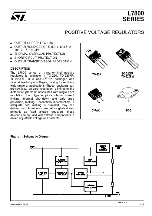
November 2016 DocID2143 Rev 34 1/54This is information on a product in full production.L78Positive voltage regulator ICsDatasheet - production dataFeatures∙ Output current up to 1.5 A∙ Output voltages of 5; 6; 8; 8.5; 9; 12; 15; 18; 24 V∙ Thermal overload protection ∙ Short circuit protection∙ Output transition SOA protection∙ 2 % output voltage tolerance (A version) ∙ Guaranteed in extended temperature range (A version)DescriptionThe L78 series of three-terminal positiveregulators is available in TO-220, TO-220FP, D²PAK and DPAK packages and several fixed output voltages, making it useful in a wide range of applications.These regulators can provide local on-card regulation, eliminating the distribution problems associated with single point regulation. Each type embeds internal current limiting, thermal shut-down and safe area protection, making it essentially indestructible. If adequate heat sinking is provided, they can deliver over 1 A output current. Although designed primarily as fixed voltage regulators, these devices can be used with external components to obtain adjustable voltage and currents.Contents L78 Contents1Diagram (3)2Pin configuration (4)3Maximum ratings (5)4Test circuits (6)5Electrical characteristics (7)6Application information (23)6.1Design consideration (23)7Typical performance (31)8Package information (33)8.1TO-220 (dual gauge) package information (34)8.2TO-220 (single gauge) package information (36)8.3TO-220FP package information (38)8.4TO-220 packing information (40)8.5DPAK package information (41)8.6D²PAK (SMD 2L STD-ST) type A package information (44)8.7D²PAK (SMD 2L Wooseok-subcon.) package information (46)8.8D²PAK and DPAK packing information (49)9Ordering information (52)10Revision history (53)L78 Diagram1 DiagramFigure 1: Block diagramPin configuration L782 Pin configurationFigure 2: Pin connections (top view)L78Maximum ratings3 Maximum ratingsAbsolute maximum ratings are those values beyond which damage to the device may occur. Functional operation under these condition is not implied.Figure 4: Application circuitsTest circuits L784 Test circuitsFigure 5: DC parameter5 Electrical characteristicsV I = 10 V, I O = 1 A, T J = 0 to 125 °C (L7805AC), T J = -40 to 125 °C (L7805AB), unlessotherwise specified aNotes:(1)Load and line regulation are specified at constant junction temperature. Changes in V O due to heating effects must be taken into account separately. Pulse testing with low duty cycle is used.a Minimum load current for regulation is 5 mA.otherwise specified aNotes:(1)Load and line regulation are specified at constant junction temperature. Changes in V O due to heating effects must be taken into account separately. Pulse testing with low duty cycle is used.a Minimum load current for regulation is 5 mA.otherwise specified aNotes:(1)Load and line regulation are specified at constant junction temperature. Changes in V O due to heating effects must be taken into account separately. Pulse testing with low duty cycle is used.a Minimum load current for regulation is 5 mA.otherwise specified aNotes:(1)Load and line regulation are specified at constant junction temperature. Changes in V O due to heating effects must be taken into account separately. Pulse testing with low duty cycle is used.a Minimum load current for regulation is 5 mA.otherwise specified aNotes:(1)Load and line regulation are specified at constant junction temperature. Changes in V O due to heating effects must be taken into account separately. Pulse testing with low duty cycle is used.a Minimum load current for regulation is 5 mA.otherwise specified aNotes:(1)Load and line regulation are specified at constant junction temperature. Changes in V O due to heating effects must be taken into account separately. Pulse testing with low duty cycle is used.a Minimum load current for regulation is 5 mA.otherwise specified aNotes:(1)Load and line regulation are specified at constant junction temperature. Changes in V O due to heating effects must be taken into account separately. Pulse testing with low duty cycle is used.a Minimum load current for regulation is 5 mA.unless otherwise specified aNotes:(1)Load and line regulation are specified at constant junction temperature. Changes in V O due to heating effects must be taken into account separately. Pulse testing with low duty cycle is used.a Minimum load current for regulation is 5 mA.unless otherwise specified aNotes:(1)Load and line regulation are specified at constant junction temperature. Changes in V O due to heating effects must be taken into account separately. Pulse testing with low duty cycle is used.a Minimum load current for regulation is 5 mA.unless otherwise specified aNotes:(1)Load and line regulation are specified at constant junction temperature. Changes in V O due to heating effects must be taken into account separately. Pulse testing with low duty cycle is used.a Minimum load current for regulation is 5 mA.Refer to the test circuits, T J = 0 to 125 °C, V I = 14.5 V, I O = 500 mA, C I = 0.33 µF,C O = 0.1 µF unless otherwise specified aNotes:(1)Load and line regulation are specified at constant junction temperature. Changes in V O due to heating effects must be taken into account separately. Pulse testing with low duty cycle is used.a Minimum load current for regulation is 5 mA.unless otherwise specified aNotes:(1)Load and line regulation are specified at constant junction temperature. Changes in V O due to heating effects must be taken into account separately. Pulse testing with low duty cycle is used.a Minimum load current for regulation is 5 mA.unless otherwise specified aNotes:(1)Load and line regulation are specified at constant junction temperature. Changes in V O due to heating effects must be taken into account separately. Pulse testing with low duty cycle is used.a Minimum load current for regulation is 5 mA.unless otherwise specified aNotes:(1)Load and line regulation are specified at constant junction temperature. Changes in V O due to heating effects must be taken into account separately. Pulse testing with low duty cycle is used.a Minimum load current for regulation is 5 mA.unless otherwise specified aNotes:(1)Load and line regulation are specified at constant junction temperature. Changes in V O due to heating effects must be taken into account separately. Pulse testing with low duty cycle is used.a Minimum load current for regulation is 5 mA.unless otherwise specified aNotes:(1)Load and line regulation are specified at constant junction temperature. Changes in V O due to heating effects must be taken into account separately. Pulse testing with low duty cycle is used.a Minimum load current for regulation is 5 mA.6 Application information6.1 Design considerationThe L78 Series of fixed voltage regulators are designed with thermal overload protectionthat shuts down the circuit when subjected to an excessive power overload condition,internal short-circuit protection that limits the maximum current the circuit will pass, andoutput transistor safe-area compensation that reduces the output short-circuit current asthe voltage across the pass transistor is increased. In many low current applications,compensation capacitors are not required. However, it is recommended that the regulatorinput be bypassed with capacitor if the regulator is connected to the power supply filter withlong lengths, or if the output load capacitance is large. An input bypass capacitor should beselected to provide good high frequency characteristics to insure stable operation under allload conditions. A 0.33 µF or larger tantalum, mylar or other capacitor having low internalimpedance at high frequencies should be chosen. The bypass capacitor should bemounted with the shortest possible leads directly across the regulators input terminals.Normally good construction techniques should be used to minimize ground loops and leadresistance drops since the regulator has no external sense lead.The addition of an operational amplifier allows adjustment to higher or intermediate valueswhile retaining regulation characteristics. The minimum voltage obtained with thearrangement is 2 V greater than the regulator voltage.The circuit of Figure 13: "High current voltage regulator" can be modified to provide supplyprotection against short circuit by adding a short circuit sense resistor, RSC, and anadditional PNP transistor. The current sensing PNP must be able to handle the short circuitcurrent of the three terminal regulator Therefore a four ampere plastic power transistor isspecified.1. Although no output capacitor is need for stability, it does improve transient response.2. Required if regulator is located an appreciable distance from power supply filter.Figure 14: High output current with short circuit protectionFigure 16: Split power supply (± 15 V - 1 A)* Against potential latch-up problems.Figure 21: High input and output voltageFigure 22: Reducing power dissipation with dropping resistorThe circuit performs well up to 100 kHz.Figure 25: Adjustable output voltage with temperature compensationQ2 is connected as a diode in order to compensate the variation of the Q1 V BE with the temperature. C allows a slow rise time of the V O.Figure 26: Light controllers (VO(min) = VXX + VBE)Application with high capacitance loads and an output voltage greater than 6 volts need an external diode (see Figure 22: "Reducing power dissipation with dropping resistor") to protect the device against input short circuit. In this case the input voltage falls rapidly while the output voltage decrease slowly. The capacitance discharges by means of the base-emitter junction of the series pass transistor in the regulator. If the energy is sufficiently high, the transistor may be destroyed. The external diode by-passes the current from the IC to ground.7 Typical performance8 Package informationIn order to meet environmental requirements, ST offers these devices in different grades ofECOPACK® packages, depending on their level of environmental compliance. ECOPACK®specifications, grade definitions and product status are available at: .ECOPACK® is an ST trademark.8.1 TO-220 (dual gauge) package information8.2 TO-220 (single gauge) package information8.3 TO-220FP package information8.4 TO-220 packing information8.5 DPAK package information8.6 D²PAK (SMD 2L STD-ST) type A package information8.7 D²PAK (SMD 2L Wooseok-subcon.) package information8.8 D²PAK and DPAK packing informationFigure 47: Tape outlineFigure 48: Reel outline。
LM7815
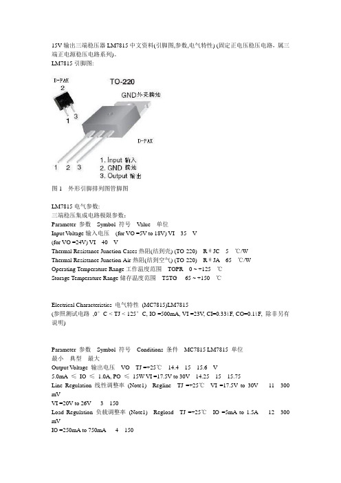
15V输出三端稳压器LM7815中文资料(引脚图,参数,电气特性) (固定正电压稳压电路,属三端正电源稳压电路系列)。
LM7815引脚图:图1 外形引脚排列图管脚图LM7815电气参数:三端稳压集成电路极限参数:Parameter 参数Symbol 符号Value 单位Input V oltage输入电压(for VO =5V to 18V) VI 35 V(for VO =24V) VI 40 VThermal Resistance Junction-Cases热阻(结到壳) (TO-220) RθJC 5 ℃/WThermal Resistance Junction-Air热阻(结到空气) (TO-220) RθJA 65 ℃/WOperating Temperature Range工作温度范围TOPR 0 ~ +125 ℃Storage Temperature Range储存温度范围TSTG -65 ~ +150 ℃Electrical Characteristics 电气特性(MC7815)LM7815(参照测试电路,0°C < TJ < 125°C, IO =500mA, VI =23V, CI=0.33ìF, CO=0.1ìF, 除非另有说明)Parameter 参数Symbol 符号Conditions 条件MC7815 LM7815 单位最小典型最大Output Voltage 输出电压VO TJ =+25℃14.4 15 15.6 V5.0mA ≤IO ≤1.0A, PO ≤15W VI =17.5V to 30V 14.25 15 15.75Line Regulation 线性调整率(Note1) Regline TJ =+25℃VI =17.5V to 30V - 11 300 mVVI =20V to 26V - 3 150Load Regulation 负载调整率(Note1) Regload TJ =+25℃IO =5mA to 1.5A - 12 300 mVIO =250mA to 750mA - 4 150Quiescent Current 静态电流IQ TJ =+25℃- 5.2 8.0 mAQuiescent Current Change 静态电流变化ΔIQ IO =5mA to 1.0A - - 0.5 mAVI =17.5V to 30V - - 1.0Output Voltage Drift 输出电压漂移ΔVO/ΔT IO =5mA - -1 - mV/℃Output Noise Voltage 输出噪声电压VN f =10Hz to 100KHz, TA =+25℃- 90 - μV/Vo Ripple Rejection 纹波抑制RR f =120Hz VI =18.5V to 28.5V 54 70 - dBDropout V oltage 电压差VDrop IO =1A, TJ=+25℃- 2 - VOutput Resistance 输出电阻rO f =1KHz - 19 - mΩShort Circuit Current 短路电流ISC VI =35V, TA=+25℃- 250 - mAPeak Current 峰值电流IPK TJ =+25℃- 2.2 - ALM7815内部原理框图图2 7809内部电路图图3 LM7815参照测试电路图4 纹波抑制电路图5 负载调节控制电路图6 与79XX系列三端稳压构成的正负对称输出电压电路图图7 LM7815典型应用电路图图8 TO-220封装图片。
LM7815中文资料
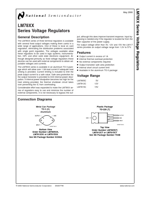
0˚C ≤ TJ ≤ 125˚C unless otherwise noted.
Output Voltage
Input Voltage (unless otherwise noted)
Symbol
Parameter
Conditions
Short-Circuit Current
Tj = 25˚C
Peak Output Current
VO
Output Voltage
Tj = 25˚C, 5 mA ≤ IO ≤ 1A
4.8 5 5.2 11.5 12 12.5 14.4 15 15.6
PD ≤ 15W, 5 mA ≤ IO ≤ 1A
4.75
5.25 11.4
12.6 14.25
15.75
VMIN ≤ VIN ≤ VMAX
(7.5 ≤ VIN ≤ 20)
Storage Temperature Range Lead Temperature (Soldering, 10 sec.)
TO-3 Package K TO-220 Package T
150˚C 150˚C −65˚C to +150˚C
300˚C 230˚C
Electrical Characteristics LM78XXC (Note 2)
0˚C ≤ TJ ≤ 125˚C unless otherwise noted.
Output Voltage
5V
12V
15V
Input Voltage (unless otherwise noted)
10V
19V
23V
Symbol
Parameter
Conditions
LM7815详细中文资料
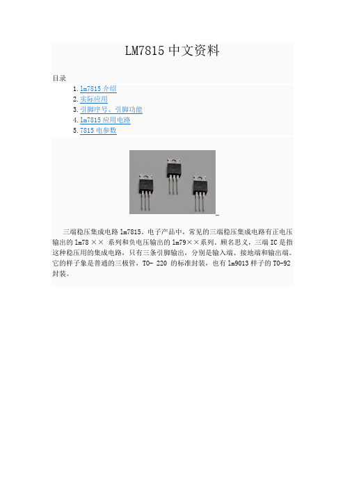
LM7815中文资料目录1.lm7815介绍2.实际应用3.引脚序号、引脚功能4.lm7815应用电路5.7815电参数三端稳压集成电路lm7815。
电子产品中,常见的三端稳压集成电路有正电压输出的lm78 ×× 系列和负电压输出的lm79××系列。
顾名思义,三端IC是指这种稳压用的集成电路,只有三条引脚输出,分别是输入端、接地端和输出端。
它的样子象是普通的三极管,TO- 220 的标准封装,也有lm9013样子的TO-92封装。
1.lm7815介绍用lm78/lm79系列三端稳压IC来组成稳压电源所需的外围元件极少,电路内部还有过流、过热及调整管的保护电路,使用起来可靠、方便,而且价格便宜。
该系列集成稳压IC型号中的lm78或lm79后面的数字代表该三端集成稳压电路的输出电压,如lm7806表示输出电压为正6V,lm7909表示输出电压为负9V。
因为三端固定集成稳压电路的使用方便,电子制作中经常采用。
最大输出电流1.5A,LM78XX系列输出电压分别为5V;6V;8V;9V;10V;12V;15V;18V;24V。
2.实际应用在实际应用中,应在三端集成稳压电路上安装足够大的散热器(当然小功率7815IC内部电路图.的条件下不用)。
当稳压管温度过高时,稳压性能将变差,甚至损坏。
当制作中需要一个能输出1.5A以上电流的稳压电源,通常采用几块三端稳压电路并联起来,使其最大输出电流为N个1.5A,但应用时需注意:并联使用的集成稳压电路应采用同一厂家、同一批号的产品,以保证参数的一致。
另外在输出电流上留有一定的余量,以避免个别集成稳压电路失效时导致其他电路的连锁烧毁。
在lm78 ** 、lm79 ** 系列三端稳压器中最常应用的是TO-220 和TO-202 两种封装。
这两种封装的图形以及引脚序号、引脚功能如附图所示。
图中的引脚号标注方法是按照引脚电位从高到底的顺序标注的。
LM340T157815中文资料

TO-220 Package (T), TO-263 Package (S) ESD Susceptibility (Note 3)
230˚C 2 kV
Operating Conditions (Note 1)
Temperature Range (TA) (Note 2) LM140 LM340A, LM340 LM7808C −55˚C to +125˚C 0˚C to +125˚C 0˚C to +125˚C
LM340A Electrical Characteristics
IOUT = 1A, 0˚C ≤ TJ ≤ + 125˚C (LM340A) unless otherwise specified (Note 4) Output Voltage Symbol VO Input Voltage (unless otherwise noted) Parameter Output Voltage TJ = 25˚C PD ≤ 15W, 5 mA ≤ IO ≤ 1A VMIN ≤ VIN ≤ VMAX ∆V O Line Regulation IO = 500 mA ∆VIN TJ = 25˚C ∆VIN TJ = 25˚C Over Temperature ∆VIN ∆V O Load Regulation TJ = 25˚C 5 mA ≤ IO ≤ 1.5A 250 mA ≤ IO ≤ 750 mA Over Temperature, 5 mA ≤ IO ≤ 1A IQ Quiescent Current Quiescent Current Change TJ = 25˚C Over Temperature ∆I Q 5 mA ≤ IO ≤ 1A TJ = 25˚C, IO = 1A VMIN ≤ VIN ≤ VMAX IO = 500 mA VMIN ≤ VIN ≤ VMAX VN Output Noise Voltage Ripple Rejection TA = 25˚C, 10 Hz ≤ f ≤ 100 kHz TJ = 25˚C, f = 120 Hz, IO = 1A or f = 120 Hz, IO = 500 mA, Over Temperature, VMIN ≤ VIN ≤ VMAX RO Dropout Voltage Output Resistance Short-Circuit Current TJ = 25˚C, IO = 1A f = 1 kHz TJ = 25˚C (8 ≤ VIN ≤ 18) 2.0 8 2.1 (15 ≤ VIN ≤ 25) 2.0 18 1.5 (18.5 ≤ VIN ≤ 28.5) 2.0 19 1.2 V V mΩ A 68 68 40 80 61 61 0.5 0.8 (7.5 ≤ VIN ≤ 20) 0.8 (8 ≤ VIN ≤ 25) 75 72 60 60 6 6.5 0.5 0.8 (14.8 ≤ VIN ≤ 27) 0.8 (15 ≤ VIN ≤ 30) 90 70 6 6.5 0.5 0.8 (17.9 ≤ VIN ≤ 30) 0.8 (17.9 ≤ VIN ≤ 30) 6 6.5 mA mA mA mA V mA V µV dB dB 10 3 Conditions 4.9 4.8 5V 10V Min Typ Max 5 5.1 5.2 10 (7.5 ≤ VIN ≤ 20) 10 4 12 (8 ≤ VIN ≤ 12) 25 15 25 12 (7.5 ≤ VIN ≤ 20) 4 Min 11.75 11.5 12V 19V Typ Max 12.5 18 (14.8 ≤ VIN ≤ 27) 18 9 30 (16 ≤ VIN ≤ 22) 32 19 60 12 (14.5 ≤ VIN ≤ 27) 4 Min 14.4 12 12.25 14.7 15V 23V Typ Max 15 15.3 15.6 22 (17.9 ≤ VIN ≤ 30) 22 10 30 (20 ≤ VIN ≤ 26) 35 21 75 (17.5 ≤ VIN ≤ 30) V V V mV V mV V mV mV V mV mV mV Unitsween SOT-223 and D-Pak (TO-252) Packages
LM7815A中文资料
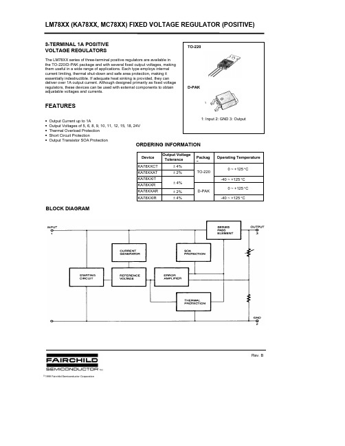
Symbol
Test Conditions
VO
∆VO ∆VO IQ ∆IQ ∆VO/∆T VN
TJ =+25 °C
5.0mA ≤ IO ≤ 1.0A, PO ≤ 15W VI = 10.5V to 23V VI = 11.5V to 23V
TJ =+ 25°C VI = 10.5V to 25V VI = 11.5V to 17V
* Load and line regulation are specified at constant junction temperature. Changes in VO due to heating effects must be taken into account separately. Pulse testing with low duty is used.
元器件交易网
LM78XX (KA78XX, MC78XX) FIXED VOLTAGE REGULATOR (POSITIVE)
LM7806/I/R/RI ELECTRICAL CHARACTERISTICS
(Refer to test circuit, TMIN <TJ <TMAX, IO=500mA, VI= 11V CI= 0.33µF, CO= 0.1µF, unless otherwise specified)
TJ
=
+25°C
IO = 5.0mA IO= 250mA
to to
1.5A 750mA
TJ =+25 °C
IO = 5mA to 1.0A
VI = 10.5A to 25V
VI = 11.5V to 25V
IO = 5mA
L7818CV中文资料
L7800
APPLICATION CIRCUIT
SCHEMATIC DIAGRAM
3/25
元器件交易网
L7800
TEST CIRCUITS Figure 1 : DC Parameter Figure 2 : Load Regulation.
Figure 3 : Ripple Rejection.
100 30 6 0.5 0.8 0.7 40 65 2 19 0.75 1.3 2.2 2.5 1.2 3.3
∆T
eN SVR Vd Ro Is c I scp
B = 10Hz to 100KHz Tj = 25 oC Vi = 9 to 19 V Io = 1 A f = 1 KHz Vi = 35 V Tj = 25 C
Symbol Vo Vo ∆ Vo * ∆Vo * Id ∆Id ∆Id ∆ Vo Parameter Output Voltage Output Voltage Line Regulation Load Regulation Quiescent Current Quiescent Current Change Quiescent Current Change Output Voltage Drift Output Noise Voltage Supply Voltage Rejection Dropout Voltage Output Resistance Short Circuit Current Short Circuit Peak Current Tj = 25 oC Io = 5 mA to 1 A Po ≤ 15 W Vi = 11.5 to 23 V Vi = 10.5 to 25 V Tj = 25 oC Vi = 11 to 17 V Tj = 25 oC Io = 5 to 1500 mA Io = 250 to 750 mA Tj = 25 C Io = 5 to 1000 mA Vi = 11.5 to 25 V Io = 5 mA B = 10Hz to 100KHz Tj = 25 oC Vi = 11.5 to 21.5 V Io = 1 A f = 1 KHz Vi = 35 V Tj = 25 C
- 1、下载文档前请自行甄别文档内容的完整性,平台不提供额外的编辑、内容补充、找答案等附加服务。
- 2、"仅部分预览"的文档,不可在线预览部分如存在完整性等问题,可反馈申请退款(可完整预览的文档不适用该条件!)。
- 3、如文档侵犯您的权益,请联系客服反馈,我们会尽快为您处理(人工客服工作时间:9:00-18:30)。
L7800SERIESPOSITIVE VOLTAGE REGULATORSJanuary 1997s OUTPUT CURRENT UP TO 1.5AsOUTPUT VOLTAGES OF 5;5.2;6;8;8.5;9;12;15;18;24Vs THERMAL OVERLOAD PROTECTION s SHORT CIRCUIT PROTECTIONsOUTPUT TRANSITION SOA PROTECTIONDESCRIPTIONThe L7800series of three-terminal positive regulators is available in TO-220ISOWATT220TO-3and D 2PAK packages and several fixed output voltages,making it useful in a wide range of applications.These regulators can provide local on-card regulation,eliminating the distribution problems associated with single point regulation.Each type employs internal current limiting,thermal shut-down and safe area protection,making it essentially indestructible.If adequate heat sinking is provided,they can deliver over 1A output current.Although designed primarily as fixed voltage regulators,these devices can be used with external components to obtain adjustable voltages and currents.12TO-3123TO-220ISOWATT22012313D 2PAKBLOCK DIAGRAM1/25CONNECTION DIAGRAM AND ORDERING NUMBERS (top view)TO-220&ISOWATT220TO-3D 2PAKTHERMAL DATASymbolParameterD 2PAK TO-220ISOWATT220TO-3UnitR t hj-case R th j-a mb Thermal Resistance Junction-case Max Thermal Resistance Junction-ambient Max 362.5350460435o C/W oC/WType TO-220D 2PAK (*)ISOWATT220TO-3Output VoltageL7805L7805C L7852C L7806L7806C L7808L7808C L7885C L7809C L7812L7812C L7815L7815C L7818L7818C L7820L7820C L7824L7824CL7805CV L7852CV L7806CV L7808CV L7885CV L7809CV L7812CV L7815CV L7818CV L7820CV L7824CVL7805CD2T L7852CD2T L7806CD2T L7808CD2T L7885CD2T L7809CD2T L7812CD2T L7815CD2T L7818CD2T L7820CD2T L7824CD2TL7805CP L7852CP L7806CP L7808CP L7885CP L7809CP L7812CP L7815CP L7818CP L7820CP L7824CPL7805T L7805CT L7852CT L7806T L7806CT L7808T L7808CT L7885CT L7809CT L7812T L7812CT L7815T L7815CT L7818T L7818CT L7820T L7820CT L7824T L7824CT5V 5V 5.2V 6V 6V 8V 8V 8.5V 9V 12V 12V 15V 15V 18V 18V 20V 20V 24V 24V(*)AVAILABLE IN TAPE AND REEL WITH ”-TR”SUFFIXABSOLUTE MAXIMUM RATINGSSymbol ParameterValue Unit V i DC Input Voltage (for V O =5to 18V)(for V O =20,24V)3540V VI o Output Current Internally limited P t ot Power DissipationInternally limited T o p Operating Junction Temperature Range (for L7800)(for L7800C )-55to 1250to 150o C o C T stgStorage Temperature Range-40to 150oCL78002/25L7800 APPLICATION CIRCUITSCHEMATIC DIAGRAM3/25TEST CIRCUITSFigure3:Ripple Rejection.Figure2:Load Regulation.Figure1:DC Parameter L78004/25ELECTRICAL CHARACTERISTICS FOR L7806(refer to the test circuits,T j =-55to 150o C,V i =15V,I o =500mA,C i =0.33µF,C o =0.1µF unless otherwise specified)Symbol ParameterTest Conditions Min.Typ.Max.Unit V o Output Voltage T j =25oC 5.756 6.25V V o Output Voltage I o =5mA to 1A P o ≤15WV i =9to 21V 5.6566.35V ∆V o *Line Regulation V i =8to 25V T j =25oCV i =9to 13VT j =25oC6030mV mV ∆V o *Load Regulation I o =5to 1500mA T j =25o CI o =250to 750mA T j =25oC10030mV mV I d Quiescent Current T j =25o C 6mA ∆I d Quiescent Current Change I o =5to 1000mA 0.5mA ∆I d Quiescent Current Change V i =9to 25V 0.8mA ∆V o ∆T Output Voltage Drift I o =5mA0.7mV/oCeN Output Noise Voltage B =10Hz to 100KHz T j =25oC 40µV/V O SVR Supply Voltage Rejection V i =9to 19V f =120Hz65dB V d Dropout Voltage I o =1A T j =25o C2 2.5V R o Output Resistance f =1KHz 19m ΩI sc Short Circuit Current V i =35V T j =25oC0.75 1.2A I s cpShort Circuit Peak CurrentT j =25o C1.32.23.3AELECTRICAL CHARACTERISTICS FOR L7805(refer to the test circuits,T j =-55to 150o C,V i =10V,I o =500mA,C i =0.33µF,C o =0.1µF unless otherwise specified)Symbol ParameterTest Conditions Min.Typ.Max.Unit V o Output Voltage T j =25oC 4.85 5.2V V o Output Voltage I o =5mA to 1A P o ≤15WV i =8to 20V 4.655 5.35V ∆V o *Line Regulation V i =7to 25V T j =25o CV i =8to 12VT j =25oC315025mV mV ∆V o *Load Regulation I o =5to 1500mA T j =25oCI o =250to 750mA T j =25oC10025mV mV I d Quiescent Current T j =25o C 6mA ∆I d Quiescent Current Change I o =5to 1000mA 0.5mA ∆I d Quiescent Current Change V i =8to 25V 0.8mA ∆V o ∆T Output Voltage Drift I o =5mA0.6mV/oCeN Output Noise Voltage B =10Hz to 100KHz T j =25o C 40µV/V O SVR Supply Voltage Rejection V i =8to 18V f =120Hz68dB V d Dropout Voltage I o =1A T j =25oC 2 2.5V R o Output Resistance f =1KHz 17m ΩI sc Short Circuit Current V i =35V T j =25oC0.75 1.2A I s cpShort Circuit Peak CurrentT j =25oC1.32.23.3A*Load and line regulation are specified at constant junction temperature.Changes in V o due to heating effects must be taken into account separately.Pulce testing with low duty cycle is used.L78005/25ELECTRICAL CHARACTERISTICS FOR L7812(refer to the test circuits,T j =-55to 150o C,V i =19V,I o =500mA,C i =0.33µF,C o =0.1µF unless otherwise specified)Symbol ParameterTest Conditions Min.Typ.Max.Unit V o Output Voltage T j =25oC11.51212.5V V o Output Voltage I o =5mA to 1A P o ≤15W V i =15.5to 27V11.41212.6V ∆V o *Line Regulation V i =14.5to 30V T j =25oCV i =16to 22V T j =25oC 12060mV mV ∆V o *Load Regulation I o =5to 1500mA T j =25o CI o =250to 750mA T j =25oC10060mV mV I d Quiescent Current T j =25o C 6mA ∆I d Quiescent Current Change I o =5to 1000mA 0.5mA ∆I d Quiescent Current Change V i =15to 30V 0.8mA ∆V o ∆T Output Voltage Drift I o =5mA1.5mV/oCeN Output Noise Voltage B =10Hz to 100KHz T j =25o C 40µV/V O SVR Supply Voltage Rejection V i =15to 25V f =120Hz61dB V d Dropout Voltage I o =1A T j =25o C2 2.5V R o Output Resistance f =1KHz 18m ΩI sc Short Circuit Current V i =35V T j =25oC0.75 1.2A I s cpShort Circuit Peak CurrentT j =25o C1.32.23.3AELECTRICAL CHARACTERISTICS FOR L7808(refer to the test circuits,T j =-55to 150o C,V i =14V,I o =500mA,C i =0.33µF,C o =0.1µF unless otherwise specified)Symbol ParameterTest Conditions Min.Typ.Max.Unit V o Output Voltage T j =25oC7.788.3V V o Output Voltage I o =5mA to 1A P o ≤15W V i =11.5to 23V7.688.4V ∆V o *Line Regulation V i =10.5to 25V T j =25o CV i =11to 17V T j =25oC 8040mV mV ∆V o *Load Regulation I o =5to 1500mA T j =25oCI o =250to 750mA T j =25oC10040mV mV I d Quiescent Current T j =25o C 6mA ∆I d Quiescent Current Change I o =5to 1000mA 0.5mA ∆I d Quiescent Current Change V i =11.5to 25V 0.8mA ∆V o ∆T Output Voltage Drift I o =5mA1mV/oCeN Output Noise Voltage B =10Hz to 100KHz T j =25o C 40µV/V O SVR Supply Voltage Rejection V i =11.5to 21.5V f =120Hz62dB V d Dropout Voltage I o =1A T j =25oC 2 2.5V R o Output Resistance f =1KHz 16m ΩI sc Short Circuit Current V i =35V T j =25oC0.75 1.2A I s cpShort Circuit Peak CurrentT j =25oC1.32.23.3A*Load and line regulation are specified at constant junction temperature.Changes in V o due to heating effects must be taken into account separately.Pulce testing with low duty cycle is used.L78006/25ELECTRICAL CHARACTERISTICS FOR L7818(refer to the test circuits,T j =-55to 150o C,V i =26V,I o =500mA,C i =0.33µF,C o =0.1µF unless otherwise specified)Symbol ParameterTest Conditions Min.Typ.Max.Unit V o Output Voltage T j =25oC 17.31818.7V V o Output Voltage I o =5mA to 1A P o ≤15W V i =22to 33V 17.11818.9V ∆V o *Line Regulation V i =21to 33V T j =25oCV i =24to 30VT j =25oC18090mV mV ∆V o *Load Regulation I o =5to 1500mA T j =25o CI o =250to 750mA T j =25oC18090mV mV I d Quiescent Current T j =25o C 6mA ∆I d Quiescent Current Change I o =5to 1000mA 0.5mA ∆I d Quiescent Current Change V i =22to 33V 0.8mA ∆V o ∆T Output Voltage Drift I o =5mA2.3mV/oCeN Output Noise Voltage B =10Hz to 100KHz T j =25oC 40µV/V O SVR Supply Voltage Rejection V i =22to 32V f =120Hz59dB V d Dropout Voltage I o =1A T j =25o C2 2.5V R o Output Resistance f =1KHz 22m ΩI sc Short Circuit Current V i =35V T j =25oC0.75 1.2A I s cpShort Circuit Peak CurrentT j =25o C1.32.23.3AELECTRICAL CHARACTERISTICS FOR L7815(refer to the test circuits,T j =-55to 150o C,V i =23V,I o =500mA,C i =0.33µF,C o =0.1µF unless otherwise specified)Symbol ParameterTest Conditions Min.Typ.Max.Unit V o Output Voltage T j =25oC14.41515.6V V o Output Voltage I o =5mA to 1A P o ≤15W V i =18.5to 30V14.251515.75V ∆V o *Line Regulation V i =17.5to 30V T j =25o CV i =20to 26V T j =25oC 15075mV mV ∆V o *Load Regulation I o =5to 1500mA T j =25oCI o =250to 750mA T j =25oC15075mV mV I d Quiescent Current T j =25o C 6mA ∆I d Quiescent Current Change I o =5to 1000mA 0.5mA ∆I d Quiescent Current Change V i =18.5to 30V 0.8mA ∆V o ∆T Output Voltage Drift I o =5mA1.8mV/oCeN Output Noise Voltage B =10Hz to 100KHz T j =25o C 40µV/V O SVR Supply Voltage Rejection V i =18.5to 28.5V f =120Hz60dB V d Dropout Voltage I o =1A T j =25oC 2 2.5V R o Output Resistance f =1KHz 19m ΩI sc Short Circuit Current V i =35V T j =25oC0.75 1.2A I s cpShort Circuit Peak CurrentT j =25oC1.32.23.3A*Load and line regulation are specified at constant junction temperature.Changes in V o due to heating effects must be taken into account separately.Pulce testing with low duty cycle is used.L78007/25ELECTRICAL CHARACTERISTICS FOR L7824(refer to the test circuits,T j =-55to 150o C,V i =33V,I o =500mA,C i =0.33µF,C o =0.1µF unless otherwise specified)Symbol ParameterTest Conditions Min.Typ.Max.Unit V o Output Voltage T j =25oC 232425V V o Output Voltage I o =5mA to 1A P o ≤15W V i =28to 38V 22.82425.2V ∆V o *Line Regulation V i =27to 38V T j =25oCV i =30to 36VT j =25oC240120mV mV ∆V o *Load Regulation I o =5to 1500mA T j =25o CI o =250to 750mA T j =25oC240120mV mV I d Quiescent Current T j =25o C 6mA ∆I d Quiescent Current Change I o =5to 1000mA 0.5mA ∆I d Quiescent Current Change V i =28to 38V 0.8mA ∆V o ∆T Output Voltage Drift I o =5mA3mV/oCeN Output Noise Voltage B =10Hz to 100KHz T j =25oC 40µV/V O SVR Supply Voltage Rejection V i =28to 38V f =120Hz56dB V d Dropout Voltage I o =1A T j =25o C2 2.5V R o Output Resistance f =1KHz 28m ΩI sc Short Circuit Current V i =35V T j =25oC0.75 1.2A I s cpShort Circuit Peak CurrentT j =25o C1.32.23.3AELECTRICAL CHARACTERISTICS FOR L7820(refer to the test circuits,T j =-55to 150o C,V i =28V,I o =500mA,C i =0.33µF,C o =0.1µF unless otherwise specified)Symbol ParameterTest Conditions Min.Typ.Max.Unit V o Output Voltage T j =25oC 19.22020.8V V o Output Voltage I o =5mA to 1A P o ≤15WV i =24to 35V192021V ∆V o *Line Regulation V i =22.5to 35V T j =25o CV i =26to 32V T j =25oC 200100mV mV ∆V o *Load Regulation I o =5to 1500mA T j =25oCI o =250to 750mA T j =25oC200100mV mV I d Quiescent Current T j =25o C 6mA ∆I d Quiescent Current Change I o =5to 1000mA 0.5mA ∆I d Quiescent Current Change V i =24to 35V 0.8mA ∆V o ∆T Output Voltage Drift I o =5mA2.5mV/oCeN Output Noise Voltage B =10Hz to 100KHz T j =25o C 40µV/V O SVR Supply Voltage Rejection V i =24to 35V f =120Hz58dB V d Dropout Voltage I o =1A T j =25oC 2 2.5V R o Output Resistance f =1KHz 24m ΩI sc Short Circuit Current V i =35V T j =25oC0.75 1.2A I s cpShort Circuit Peak CurrentT j =25oC1.32.23.3A*Load and line regulation are specified at constant junction temperature.Changes in V o due to heating effects must be taken into account separately.Pulce testing with low duty cycle is used.L78008/25ELECTRICAL CHARACTERISTICS FOR L7852C (refer to the test circuits,T j =0to 125o C,V i =10V,I o =500mA,C i =0.33µF,C o =0.1µF unless otherwise specified)Symbol ParameterTest Conditions Min.Typ.Max.Unit V o Output Voltage T j =25oC 5.0 5.2 5.4V V o Output Voltage I o =5mA to 1A P o ≤15WV i =8to 20V 4.955.2 5.45V ∆V o *Line Regulation V i =7to 25V T j =25oCV i =8to 12VT j =25oC3110552mV mV ∆V o *Load Regulation I o =5to 1500mA T j =25o CI o =250to 750mA T j =25oC10552mV mV I d Quiescent Current T j =25o C 8mA ∆I d Quiescent Current Change I o =5to 1000mA 0.5mA ∆I d Quiescent Current Change V i =7to 25V 1.3mA ∆V o ∆T Output Voltage Drift I o =5mA-1.0mV/oC eN Output Noise Voltage B =10Hz to 100KHz T j =25oC 42µV SVR Supply Voltage Rejection V i =8to 18V f =120Hz61dB V d Dropout Voltage I o =1A T j =25o C2V R o Output Resistance f =1KHz 17m ΩI sc Short Circuit Current V i =35V T j =25oC750mA I s cpShort Circuit Peak CurrentT j =25o C2.2AELECTRICAL CHARACTERISTICS FOR L7805C (refer to the test circuits,T j =0to 125o C,V i =10V,I o =500mA,C i =0.33µF,C o =0.1µF unless otherwise specified)Symbol ParameterTest Conditions Min.Typ.Max.Unit V o Output Voltage T j =25oC 4.85 5.2V V o Output Voltage I o =5mA to 1A P o ≤15WV i =7to 20V 4.755 5.25V ∆V o *Line Regulation V i =7to 25V T j =25o CV i =8to 12VT j =25oC3110050mV mV ∆V o *Load Regulation I o =5to 1500mA T j =25oCI o =250to 750mA T j =25oC10050mV mV I d Quiescent Current T j =25o C 8mA ∆I d Quiescent Current Change I o =5to 1000mA 0.5mA ∆I d Quiescent Current Change V i =7to 25V 0.8mA ∆V o ∆T Output Voltage Drift I o =5mA-1.1mV/oC eN Output Noise Voltage B =10Hz to 100KHz T j =25o C 40µV SVR Supply Voltage Rejection V i =8to 18V f =120Hz62dB V d Dropout Voltage I o =1A T j =25oC2V R o Output Resistance f =1KHz 17m ΩI sc Short Circuit Current V i =35V T j =25oC750mA I s cpShort Circuit Peak CurrentT j =25oC2.2A*Load and line regulation are specified at constant junction temperature.Changes in V o due to heating effects must be taken into account separately.Pulce testing with low duty cycle is used.L78009/25ELECTRICAL CHARACTERISTICS FOR L7808C (refer to the test circuits,T j =0to 125o C,V i =14V,I o =500mA,C i =0.33µF,C o =0.1µF unless otherwise specified)Symbol ParameterTest Conditions Min.Typ.Max.Unit V o Output Voltage T j =25oC7.788.3V V o Output Voltage I o =5mA to 1A P o ≤15W V i =10.5to 25V7.688.4V ∆V o *Line Regulation V i =10.5to 25V T j =25oCV i =11to 17V T j =25oC 16080mV mV ∆V o *Load Regulation I o =5to 1500mA T j =25o CI o =250to 750mA T j =25oC16080mV mV I d Quiescent Current T j =25o C 8mA ∆I d Quiescent Current Change I o =5to 1000mA 0.5mA ∆I d Quiescent Current Change V i =10.5to 25V 1mA ∆V o ∆T Output Voltage Drift I o =5mA-0.8mV/oC eN Output Noise Voltage B =10Hz to 100KHz T j =25o C 52µV SVR Supply Voltage Rejection V i =11.5to 21.5V f =120Hz56dB V d Dropout Voltage I o =1A T j =25o C2V R o Output Resistance f =1KHz 16m ΩI sc Short Circuit Current V i =35V T j =25oC450mA I s cpShort Circuit Peak CurrentT j =25o C2.2AELECTRICAL CHARACTERISTICS FOR L7806C (refer to the test circuits,T j =0to 125o C,V i =11V,I o =500mA,C i =0.33µF,C o =0.1µF unless otherwise specified)Symbol ParameterTest Conditions Min.Typ.Max.Unit V o Output Voltage T j =25oC 5.756 6.25V V o Output Voltage I o =5mA to 1A P o ≤15WV i =8to 21V 5.766.3V ∆V o *Line Regulation V i =8to 25V T j =25o CV i =9to 13VT j =25oC12060mV mV ∆V o *Load Regulation I o =5to 1500mA T j =25oCI o =250to 750mA T j =25oC12060mV mV I d Quiescent Current T j =25o C 8mA ∆I d Quiescent Current Change I o =5to 1000mA 0.5mA ∆I d Quiescent Current Change V i =8to 25V 1.3mA ∆V o ∆T Output Voltage Drift I o =5mA-0.8mV/oC eN Output Noise Voltage B =10Hz to 100KHz T j =25o C 45µV SVR Supply Voltage Rejection V i =9to 19V f =120Hz59dB V d Dropout Voltage I o =1A T j =25oC 2V R o Output Resistance f =1KHz 19m ΩI sc Short Circuit Current V i =35V T j =25oC550mA I s cpShort Circuit Peak CurrentT j =25oC2.2A*Load and line regulation are specified at constant junction temperature.Changes in V o due to heating effects must be taken into account separately.Pulce testing with low duty cycle is used.L780010/25ELECTRICAL CHARACTERISTICS FOR L7809C (refer to the test circuits,T j =0to 125o C,V i =15V,I o =500mA,C i =0.33µF,C o =0.1µF unless otherwise specified)Symbol ParameterTest Conditions Min.Typ.Max.Unit V o Output Voltage T j =25oC8.6599.35V V o Output Voltage I o =5mA to 1A P o ≤15W V i =11.5to 26V8.5599.45V ∆V o *Line Regulation V i =11.5to 26V T j =25oCV i =12to 18V T j =25oC 18090mV mV ∆V o *Load Regulation I o =5to 1500mA T j =25o CI o =250to 750mA T j =25oC18090mV mV I d Quiescent Current T j =25o C 8mA ∆I d Quiescent Current Change I o =5to 1000mA 0.5mA ∆I d Quiescent Current Change V i =11.5to 26V 1mA ∆V o ∆T Output Voltage Drift I o =5mA-1.0mV/oC eN Output Noise Voltage B =10Hz to 100KHz T j =25o C 70µV SVR Supply Voltage Rejection V i =12to 23V f =120Hz55dB V d Dropout Voltage I o =1A T j =25o C2V R o Output Resistance f =1KHz 17m ΩI sc Short Circuit Current V i =35V T j =25oC400mA I s cpShort Circuit Peak CurrentT j =25o C2.2AELECTRICAL CHARACTERISTICS FOR L7885C (refer to the test circuits,T j =0to 125o C,V i =14.5V,I o =500mA,C i =0.33µF,C o =0.1µF unless otherwise specified)Symbol ParameterTest Conditions Min.Typ.Max.Unit V o Output Voltage T j =25oC 8.28.58.8V V o Output Voltage I o =5mA to 1A P o ≤15WV i =11to 26V8.18.58.9V ∆V o *Line Regulation V i =11to 27V T j =25o CV i =11.5to 17.5V T j =25oC 16080mV mV ∆V o *Load Regulation I o =5to 1500mA T j =25oCI o =250to 750mA T j =25oC16080mV mV I d Quiescent Current T j =25o C 8mA ∆I d Quiescent Current Change I o =5to 1000mA 0.5mA ∆I d Quiescent Current Change V i =11to 27V 1mA ∆V o ∆T Output Voltage Drift I o =5mA-0.8mV/oC eN Output Noise Voltage B =10Hz to 100KHz T j =25o C 55µV SVR Supply Voltage Rejection V i =12to 22V f =120Hz56dB V d Dropout Voltage I o =1A T j =25oC2V R o Output Resistance f =1KHz 16m ΩI sc Short Circuit Current V i =35V T j =25oC450mA I s cpShort Circuit Peak CurrentT j =25oC2.2A*Load and line regulation are specified at constant junction temperature.Changes in V o due to heating effects must be taken into account separately.Pulce testing with low duty cycle is used.11/25ELECTRICAL CHARACTERISTICS FOR L7815C (refer to the test circuits,T j =0to 125o C,V i =23V,I o =500mA,C i =0.33µF,C o =0.1µF unless otherwise specified)Symbol ParameterTest Conditions Min.Typ.Max.Unit V o Output Voltage T j =25oC14.41515.6V V o Output Voltage I o =5mA to 1A P o ≤15W V i =17.5to 30V14.251515.75V ∆V o *Line Regulation V i =17.5to 30V T j =25oCV i =20to 26V T j =25oC 300150mV mV ∆V o *Load Regulation I o =5to 1500mA T j =25o CI o =250to 750mA T j =25oC300150mV mV I d Quiescent Current T j =25o C 8mA ∆I d Quiescent Current Change I o =5to 1000mA 0.5mA ∆I d Quiescent Current Change V i =17.5to 30V 1mA ∆V o ∆T Output Voltage Drift I o =5mA-1mV/oC eN Output Noise Voltage B =10Hz to 100KHz T j =25o C 90µV SVR Supply Voltage Rejection V i =18.5to 28.5V f =120Hz54dB V d Dropout Voltage I o =1A T j =25o C2V R o Output Resistance f =1KHz 19m ΩI sc Short Circuit Current V i =35V T j =25oC230mA I s cpShort Circuit Peak CurrentT j =25o C2.1AELECTRICAL CHARACTERISTICS FOR L7812C (refer to the test circuits,T j =0to 125o C,V i =19V,I o =500mA,C i =0.33µF,C o =0.1µF unless otherwise specified)Symbol ParameterTest Conditions Min.Typ.Max.Unit V o Output Voltage T j =25oC11.51212.5V V o Output Voltage I o =5mA to 1A P o ≤15W V i =14.5to 27V11.41212.6V ∆V o *Line Regulation V i =14.5to 30V T j =25o CV i =16to 22V T j =25oC 240120mV mV ∆V o *Load Regulation I o =5to 1500mA T j =25oCI o =250to 750mA T j =25oC240120mV mV I d Quiescent Current T j =25o C 8mA ∆I d Quiescent Current Change I o =5to 1000mA 0.5mA ∆I d Quiescent Current Change V i =14.5to 30V 1mA ∆V o ∆T Output Voltage Drift I o =5mA-1mV/oC eN Output Noise Voltage B =10Hz to 100KHz T j =25o C 75µV SVR Supply Voltage Rejection V i =15to 25V f =120Hz55dB V d Dropout Voltage I o =1A T j =25oC2V R o Output Resistance f =1KHz 18m ΩI sc Short Circuit Current V i =35V T j =25oC350mA I s cpShort Circuit Peak CurrentT j =25o C2.2A*Load and line regulation are specified at constant junction temperature.Changes in V o due to heating effects must be taken into account separately.Pulce testing with low duty cycle is used.12/25ELECTRICAL CHARACTERISTICS FOR L7820C (refer to the test circuits,T j =0to 125o C,V i =28V,I o =500mA,C i =0.33µF,C o =0.1µF unless otherwise specified)Symbol ParameterTest Conditions Min.Typ.Max.Unit V o Output Voltage T j =25oC 19.22020.8V V o Output Voltage I o =5mA to 1A P o ≤15WV i =23to 35V192021V ∆V o *Line Regulation V i =22.5to 35V T j =25oCV i =26to 32V T j =25oC 400200mV mV ∆V o *Load Regulation I o =5to 1500mA T j =25o CI o =250to 750mA T j =25oC400200mV mV I d Quiescent Current T j =25o C 8mA ∆I d Quiescent Current Change I o =5to 1000mA 0.5mA ∆I d Quiescent Current Change V i =23to 35V 1mA ∆V o ∆T Output Voltage Drift I o =5mA-1mV/oC eN Output Noise Voltage B =10Hz to 100KHz T j =25oC 150µV SVR Supply Voltage Rejection V i =24to 35V f =120Hz52dB V d Dropout Voltage I o =1A T j =25o C2V R o Output Resistance f =1KHz 24m ΩI sc Short Circuit Current V i =35V T j =25oC180mA I s cpShort Circuit Peak CurrentT j =25o C2.1AELECTRICAL CHARACTERISTICS FOR L7818C (refer to the test circuits,T j =0to 125o C,V i =26V,I o =500mA,C i =0.33µF,C o =0.1µF unless otherwise specified)Symbol ParameterTest Conditions Min.Typ.Max.Unit V o Output Voltage T j =25oC 17.31818.7V V o Output Voltage I o =5mA to 1A P o ≤15W V i =21to 33V 17.11818.9V ∆V o *Line Regulation V i =21to 33V T j =25o CV i =24to 30VT j =25oC360180mV mV ∆V o *Load Regulation I o =5to 1500mA T j =25oCI o =250to 750mA T j =25oC360180mV mV I d Quiescent Current T j =25o C 8mA ∆I d Quiescent Current Change I o =5to 1000mA 0.5mA ∆I d Quiescent Current Change V i =21to 33V 1mA ∆V o ∆T Output Voltage Drift I o =5mA-1mV/oC eN Output Noise Voltage B =10Hz to 100KHz T j =25o C 110µV SVR Supply Voltage Rejection V i =22to 32V f =120Hz53dB V d Dropout Voltage I o =1A T j =25oC2V R o Output Resistance f =1KHz 22m ΩI sc Short Circuit Current V i =35V T j =25oC200mA I s cpShort Circuit Peak CurrentT j =25oC2.1A*Load and line regulation are specified at constant junction temperature.Changes in V o due to heating effects must be taken into account separately.Pulce testing with low duty cycle is used.13/25*Load and line regulation are specified at constant junction temperature.Changes in V o due to heating effects must be taken into account separately.Pulce testing with low duty cycle is used.ELECTRICAL CHARACTERISTICS FOR L7824C (refer to the test circuits,T j =0to 125o C,V i =33V,I o =500mA,C i =0.33µF,C o =0.1µF unless otherwise specified)Symbol ParameterTest Conditions Min.Typ.Max.Unit V o Output Voltage T j =25oC 232425V V o Output Voltage I o =5mA to 1A P o ≤15W V i =27to 38V 22.82425.2V ∆V o *Line Regulation V i =27to 38V T j =25o CV i =30to 36VT j =25oC480240mV mV ∆V o *Load Regulation I o =5to 1500mA T j =25oCI o =250to 750mA T j =25oC480240mV mV I d Quiescent Current T j =25o C 8mA ∆I d Quiescent Current Change I o =5to 1000mA 0.5mA ∆I d Quiescent Current Change V i =27to 38V 1mA ∆V o ∆T Output Voltage Drift I o =5mA-1.5mV/oC eN Output Noise Voltage B =10Hz to 100KHz T j =25o C 170µV SVR Supply Voltage Rejection V i =28to 38V f =120Hz50dB V d Dropout Voltage I o =1A T j =25oC2V R o Output Resistance f =1KHz 28m ΩI sc Short Circuit Current V i =35V T j =25oC150mA I s cpShort Circuit Peak CurrentT j =25oC2.1A14/25Figure 8:Output Impedance vs.Frequency.Figure 9:Quiescent Current vs.JunctionTemperature.Figure 4:Dropout Voltage vs.JunctionTemperature.Figure 5:Peak Output Current vs.Input/outputDifferential Voltage.Figure 6:Supply Voltage Rejection vs.Frequency.Figure 7:Output Voltage vs.JunctionTemperature.15/25Figure12:Quiescent Current vs.InputVoltage.Figure13:Fixed Output Regulator.Figure14:Current Regulator. Figure10:Load Transient Response.Figure11:Line Transient Response.NOTE:1.To specify an output voltage,substitute voltage value for”XX”.2.Although no output capacitor is need for stability,it does improve transient response.3.Required if cregulator is locate an appreciable distance from power supply filter.I O=V XXR1+I d16/25Figure 15:Circuit for Increasing OutputVoltage.Figure 16:Adjustable Output Regulator(7to 30V).Figure 17:0.5to 10V Regulator.Figure 18:High Current Voltage Regulator.I R1≥5I d V O =V XX (1+R 2R 1)+I d R 2VO =V XXR 4R 1R 1=V BEQ 1I REQ −I Q 1βQ 1I O =I REG +Q 1(I REG −V BEQ 1R 1)17/25Figure 19:High Output Current with ShortCircuit Protection.Figure 20:Tracking Voltage Regulator.Figure 21:Split Power Supply (±15V –1A).Figure 22:Negative Output Voltage Circuit.Figure 23:Switching Regulator.Figure 24:High Input Voltage Circuit.V IN =V i -(V Z +V BE )*Against potential latch-up problems.R SC =V BEQ 2I SC18/25Figure 27:High Input and Output Voltage.Figure 28:Reducing Power Dissipation withDr opping Resistor.Figure 29:Remote Shutdown.Figure 25:High Input Voltage Circuit.Figure 26:High Output Voltage Regulator.V O =V XX +V Z1R =V i (min )−V XX −V DROP (max )I O (max )+I d (max )19/25Figure 30:Power AM Modulator (unity voltagegain,I o <1A).Figure 31:Adjustable Output Voltage withTemperatureCompensation.NOTE:The circuit performs well up to 100KHzNOTE:Q 2is connected as a diode in order to compensate the variation of the Q 1V BE with the temperature.C allows a slow rise-time of the V oFigure 32:Light Controllers (V o min =V xx +V BE ).Figure 33:Protection against Input Short-circuitwith High Capacitance Loads.Application with high capacitance loads and an output voltage greater than 6volts need an external diode (see fig.33)to protect the deviceagainst input short circuit.In this case the input voltage falls rapidly while the output voltage decrease slowly.The capacitance dischrges by means of the Base-Emitter junction of the series pass transistor in the regulator.If the energy is sufficently high,the transistor may be destroyed.The external diode by-passes the current from the IC to ground.V O falls when the light goes upV O rises when the light goes upV O =VXX(1+R 2R 1)+V BE 20/25。
