红外分析仪
傅里叶红外光谱仪的用途

傅里叶红外光谱仪的用途傅里叶红外光谱仪,又称红外分析仪,是一种可用于分析有机物和无机物结构的仪器。
它利用物质在红外辐射下的吸收、透过或反射性质,通过对傅里叶变换的处理,得出物质分子中的化学键种类、数量及分子结构信息。
下面我们来看看它在哪些方面有用。
一、化学分析领域傅里叶红外光谱仪在化学分析领域中有着广泛的应用。
例如,它可以用于有机化合物、无机化合物和高分子等的检测、鉴定、成分分析和结构确定等领域,如脂肪酸、脂肪醇、含氯有机化合物、多肽和蛋白质等。
二、制药领域傅里叶红外光谱仪在制药领域中的应用主要体现在对药品的质量控制方面。
药品质量的控制离不开技术手段的支持。
傅里叶红外光谱仪可以通过检测各种物质的红外光谱来证明药品的化学品质,进而保证药品的质量和疗效,防止药品的不良反应和副作用。
三、食品检测领域傅里叶红外光谱仪在食品检测领域中也有着广泛的应用。
例如,可以用于食品中的脂肪酸、脂肪醇、糖类、氨基酸等物质的检测和分析,进而可以保证食品的质量安全,防止食品中的不良成分对人体造成的危害。
四、环境科学领域傅里叶红外光谱仪在环境科学领域中也有着重要的应用。
例如,可以用于大气中的气态污染物、水中的有机物以及土地中的有害物质等的检测和分析,为环境污染监测和治理提供有力的技术手段。
五、生物医学领域傅里叶红外光谱仪在生物医学领域中起到了重要的作用。
例如可以用于人体内的脂肪代谢、糖代谢、蛋白质合成等各种物质的检测和分析,可以为生物医学研究提供有力的技术手段。
总之,傅里叶红外光谱仪在各个领域中都有着广泛的应用。
在未来的发展中,它将继续为人们提供更为精确、准确的检测手段,推动各个领域的科技进步。
红外气体分析仪原理

红外气体分析仪原理
红外气体分析仪的工作原理是利用红外辐射与气体分子之间的相互作用来识别和测量气体的类型和浓度。
其主要原理包括红外光源、样品室、检测器和数据处理系统。
首先,红外光源产生特定频率的红外光束,并通过光学系统引导到样品室。
红外光会穿过样品室,射向内部的待测气体。
当红外光束通过气体时,气体分子会吸收特定频率的红外光能量。
吸收的光的强度与气体中特定分子的浓度相关。
接下来,检测器会测量并比较红外光源发出的光与通过样品室后的光的差异。
任何被气体分子吸收的红外光都会使检测器输出信号产生变化。
最后,数据处理系统会分析检测器输出信号,通过对比事先设定的气体吸收谱线和实际测量的谱线,来确定待测气体的种类和浓度。
红外气体分析仪具有快速、准确和灵敏的特点,并广泛应用于环境监测、工业过程控制以及安全防护等领域。
红外分析仪构成、原理
1红外分析仪构成1.1红外线气体分析仪红外线气体分析仪是基于红外检测原理,属于光学分析仪器中的一种。
它是利用不同气体对不同波长的红外线具有特殊的吸收能力来实现气体的组分检测的。
红外线式气体检测主要利用了气体对红外线的波长有选择的可吸收型和热效应两个特点。
红外线气体分析器是一种吸收式的、不分光型的气休分析器。
所谓吸收式即利用气体对电磁波的吸收特性。
不分光型也称为非色散型,即光源发射出连续光谱的射线,全部投射到被分析的气样上去。
利用气体的特征吸收波长及其积分特性进行定性和定量的分析,大部分的有机和无机气体在红外波段内都有其特征吸收峰。
有的气体还有两个或多个特证吸收峰。
具有对称结构的、无极性的双原子分子气体,如O2、H2等,以及单原子分子气体,例如Ar等,在红外线彼段内没有特征吸收峰。
因此红外线气体分析仪对这种双原子和单原子分子气体不能进行分析测量,每一台红外线气体分析器只能分析一种气体,例如一台CO2红外线气体分析器,它可以从一个多组分的混合气体中分析出CO2的体积百分比浓度,如果背景气体中的某一组分在红外线波段内有与CO2的特征吸收峰重迭的部分。
那么我们称这种背景气体为干扰组分,因此在气样进人红外线气体分析仪之前要把这种干拢组分去除掉。
水蒸汽在2.6-10µm这个很宽的波段范圈内有吸收的特性。
因此水蒸汽对红外线气体分析器来讲是一种重要的干扰组分,在分析之前都要对样气进行干燥处理,去除水分,这样才能保证测量的准确性。
红外线气体分析器的工作原理:用人工方法制造一个包括被测气体特征吸收峰波长在内的连续光谱的辐射源,让这个连续光谱通过固定厚度的含有被测气体的混合组分,在混合组分的气体层中,被测气体的浓度不同,吸收固定波长红外线的能量也不相同。
继而转换成的热量也不相同,在一个特制的红外检测器中再将热量转换成温度或压力,测量这个温度或压力就可以准确地测量出被分析气体的浓度,从朗伯特一比耳定律来看,I=I o e-kcl,就是要使红外线气体分析器辐射源的发射能量连续地通过一定厚度的被分析气样,也就是说使I o、K、L确定下来。
红外烟气分析仪原理
红外烟气分析仪原理
红外烟气分析仪(Infrared Smoke Analyzer)是一种用于测量
和分析烟气中污染物浓度的仪器。
它基于红外光吸收原理,通过检测红外光在气体中的吸收程度,来确定烟气中各种污染物的含量。
红外烟气分析仪采用了红外光源和红外光接收器。
红外光源发射出被测气体所吸收的特定波长的红外光,并通过被测气体后的光束到达红外光接收器。
红外光接收器测量红外光的强度,并将其转换为电信号。
当红外光通过烟气时,烟气中的污染物会吸收特定波长的红外光。
不同的污染物对红外光的吸收程度具有特定的特征,因而可以通过测量吸收的光强度来推断污染物的浓度。
红外烟气分析仪使用一系列不同波长的红外光,以覆盖各种可能的污染物。
它可以通过多个通道同时测量不同污染物的浓度,并将结果显示在仪器的显示屏上。
红外烟气分析仪的应用领域非常广泛,包括环境监测、工艺控制、烟气排放监测等。
其优点在于测量速度快、准确性高、使用方便,并且能同时测量多种污染物的浓度。
由于红外烟气分析仪采用了非接触式的测量方法,因此可以实时监测烟气中的污染物浓度,无需对气体进行取样和处理,大大提高了工作效率。
此外,红外烟气分析仪还具有较高的抗干扰能力,可以在复杂的烟气环境下正常运行。
红外线光谱分析仪安全操作及保养规程
红外线光谱分析仪安全操作及保养规程红外线光谱分析仪是一种重要的实验仪器,在化学分析、药物研究等领域有着广泛的应用。
然而,由于红外线光谱分析仪具有一定的辐射性和化学危险性,因此在使用时必须遵循一定的安全操作规程,同时也需要进行定期的保养和维护。
本文将详细介绍红外线光谱分析仪的安全操作规程以及保养维护规程,以确保实验人员的人身安全和仪器的长期使用寿命。
一、红外线光谱分析仪安全操作规程1.在使用前必须仔细阅读使用手册,熟悉仪器的使用方法和注意事项,遵循使用手册中的操作流程。
2.使用前需检查仪器性能是否正常,如果发现故障或异常情况应及时通知相关人员进行检修。
3.在使用红外线光谱分析仪时,必须正确接地,以减少静电干扰和保护人身安全。
4.避免在微粒扬尘过多的环境下使用仪器,将仪器放置在通风良好的地方,以避免产生有毒、危险气体。
5.不得私自更换或拆除设备零部件,必须由专业人员进行维修和更换。
6.在使用红外线光谱分析仪时,不得将手指或其他物体伸进样品室内,以免触及样品或其他危险部位。
7.在操作过程中,应保持安静,不得喧哗或进行其他无关操作,以确保实验过程顺利进行。
8.完成使用后,应及时关闭设备电源,并进行仪器清洁和消毒,以确保下一次使用。
二、红外线光谱分析仪保养维护规程1.定期进行仪器的日常清洁和消毒,避免仪器表面积累过多的污垢和保护薄膜。
2.定期进行仪器的校准和维护,确保设备性能和测量精度。
3.定期更换仪器中的易损件,如光源、检测器等,以确保仪器的长期使用寿命。
4.存放仪器时,将仪器放置在通风、干燥、无尘的地方,并进行覆盖保护,以防止粉尘、雨水、阳光等有害物质对仪器的损害。
5.定期对仪器进行防护性维护,如防潮、防锈、防磁等措施,以确保仪器的正常使用状态。
6.定期对仪器及其相关设备进行防盗和防火措施,以确保设备的安全和完整。
结论红外线光谱分析仪的使用和保养是维护实验过程和实验人员安全的重要措施。
本文介绍了红外线光谱分析仪的安全操作规程和保养维护规程,并提出了一些实用的方法和建议,希望能为实验人员提供一些有益的参考和指导。
红外线分析仪的作用与应用

红外线分析仪的作用与应用什么是红外线分析仪红外线分析仪(Infrared Spectrometer)也称为红外线光谱仪,是一种利用物质分子在特定波长的红外光的区域内吸收或发生散射、反射而得到样品的光谱特征的仪器设备。
其原理是将白炽灯等光源发出的光通过一个分光装置将光分为多种波长的光,然后照射到测试物质表面与其相互作用,最后记录下被测试物质所吸收、散射或反射的光谱信息。
红外线分析仪的作用红外线分析仪适用于各种物质的物理、化学性质分析,广泛用于工业、农业、医学、环保及科研等领域。
具有如下几个特点:1. 高灵敏度红外线分析仪可对物质的分子构成进行详细分析,其灵敏度高,可检测到样品中微量成分的存在。
2. 快速分析与其他传统的分析方法相比,红外线分析仪具有方法简单、快速分析、精度高等优点,可以有效提高工序中的分析效率。
3. 可靠性强红外线分析仪可以通过对样品分子的振动吸收谱进行分析,可以对样品的物理、化学等性质进行准确的分析。
通过对样品的特殊光谱分析,可以在无需破坏样品的情况下,对样品的特定分子成分进行分析,也可以详细鉴别材料的成分、内部结构以及化学状态等。
红外线分析仪的应用红外线分析仪在各个领域中都有广泛的应用,以下是几个常见的应用:1. 化学行业在化学制造行业中,红外线分析仪可以快速分析化学物品的结构和性质,同时可以检测有毒或有害化学物质,以确保产品的质量和安全性。
2. 医学领域在医学领域中,红外线分析仪可以用于检测生物分子,例如蛋白质、DNA或RNA等。
此外,它也可以用来确定药物中的活性成分和化合物配方,从而确定药品质量。
3. 石油行业在石油行业中,红外线分析仪可以用来检测石油中的化学组分,例如,红外线分析仪可以用来检测石油中的硫化氢、二氧化碳、氨气等。
4. 食品分析在食品行业中,红外线分析仪可以用来检测食品中的成分和营养素,例如,化学成分、脂肪含量、果糖含量、蛋白质含量、氨基酸含量等。
5. 环境领域在环境领域中,红外线分析仪可以用来检测大气中的气态物质,例如,S02、NOx等;也可以用于测定各种环境污染物,如甲醛、苯、酚等。
红外光谱仪操作规程
红外光谱仪操作规程《红外光谱仪操作规程》一、引言红外光谱仪是一种用于分析样品中的分子结构和化学成分的仪器。
它通过对样品激发并测量样品辐射的红外光的方式来进行分析。
正确操作红外光谱仪对于获取准确的分析结果至关重要,因此有必要建立一套操作规程来保证仪器的正确使用。
二、操作准备1. 打开红外光谱仪电源,等待仪器自检完成。
2. 检查样品室和样品支撑平台是否清洁,有无异物。
3. 准备好需要测试的样品,并将其放置在样品支撑平台上。
三、仪器校准1. 进行零点校准,将空气对流区设定为零基线。
2. 使用标准样品进行波数校准,确保仪器的波数测量准确。
四、样品测试1. 选择适当的测试模式和参数设置。
2. 将样品放置在样品支撑平台上,并确保样品与红外光谱仪的检测区域对齐。
3. 开始测试,并记录测试时间和条件。
五、数据处理1. 获取红外光谱图谱,并保存数据。
2. 对测试数据进行分析,提取出需要的信息。
六、仪器维护1. 测试结束后,关闭红外光谱仪电源。
2. 清洁样品室和样品支撑平台,确保仪器的卫生和整洁。
3. 定期对仪器进行维护保养,保证其正常使用。
七、安全注意事项1. 使用红外光谱仪时,注意避免直接暴露在红外光线下,以免对眼睛造成伤害。
2. 操作过程中,尽量避免样品在样品支撑平台上发生滑动或晃动。
八、结语红外光谱仪是一种非常重要的分析仪器,准确操作和维护对于保证分析结果的准确性至关重要。
遵守本操作规程,可以有效保护仪器和提高操作人员的安全意识,保证分析结果的可靠性。
红外分析仪检查
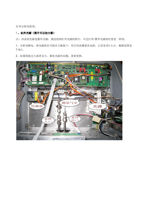
红外分析仪检查:
1.、红外光源(图片可以拉大看)
注:该表的光源是紫外光源,我没找到红外光源的照片,不过红外/紫外光源的位置是一样的。
1、分析仪断电,将光源的信号线从主板拔下,用万用表测量其电阻,正常是8Ω左右,极限范围是7~9Ω。
2、如果阻值过大或者过小,都是光源有问题,需要更换。
2、检测器(图片可以拉大看)
1、将分析仪断电,拆下检测器外壳。
2、分析仪上电,用万用表测量检测器的+、—端(直流电压档),检测器的工作电压应为12VDC左右,如果没有电压,则需要检查主板输出是否正常,必要时更换主板。
3、用万用表测量检测器的A、⊥端(交流电压档),正常值在1~8VAC之间,且通入零点/量程/采样气体,该电压会变化,约在0.2~0.5VAC左右。
4、如果测量电压为0VAC左右,则表明该检测器没有信号输出,此时分析仪显示值是一个死值(通入气体,读数不变化)。
可判断检测器坏,需要更换。
红外光谱分析仪基础知识

用于研究生物分子结构和功能,辅助药物研发和 疾病诊断。
3
农业领域
检测农产品中的营养成分和农药残留,保障食品 安全。
行业标准与规范建立
制定统一的仪器性能评价标准
01
规范不同厂商生产的红外光谱分析仪的性能指标。
建立数据共享与互操作标准
02
促进不同仪器之间的数据交换与共享,提高分析结果的可靠性。
样品不纯
采用纯度较高的样品进行 测试,或采用内标法进行 校正。
光谱干扰
检查光谱图是否存在其他 物质的干扰,如水蒸气、 二氧化碳等。
仪器误差
定期对仪器进行校准,确 保仪器性能稳定。
样品制备技巧与注意事项
样品量控制
根据测试需求选择合适的样品量,避免过多或过少。
样品处理
对于不透明的样品,需要进行适当处理以获得准确的 光谱图。
制定安全操作与维护规范
03
确保仪器使用过程中的安全,延长仪器使用寿命。
THANKS FOR WATCHING
感谢您的观看
应用领域与优势
应用领域
化学、医药、食品、环保、农业、能源等领域。
优势
能够快速准确地分析物质成分和结构,提供丰富的分子结构和化学信息,有助 于科研和生产过程中的质量控制、产品开发以及环境监测等。
02 红外光谱分析仪的基本组 成
ቤተ መጻሕፍቲ ባይዱ
光源系统
总结词
光源系统是红外光谱分析仪的核心部分,负责产生入射到样品的光线。
工作原理
当红外光与物质相互作用时,物质分 子吸收特定波长的红外光,产生分子 振动和转动能级跃迁,通过测量吸收 光谱,可以分析物质成分和结构。
分类与特点
分类
根据应用领域和测量精度,红外 光谱分析仪可分为傅里叶变换红 外光谱仪、色散型红外光谱仪、 光声光谱仪等。
红外分析仪
红外分析仪红外分析仪是一种广泛应用于科研、工业、医疗等领域的分析仪器。
它可以通过测量物质在红外光线作用下的吸收谱,获取物质的结构信息和成分组成,为研究和分析提供了有力的工具。
本文将从红外分析仪的原理、应用领域和发展前景等方面进行探讨。
红外分析仪的原理基于物质在红外光线作用下吸收特定波长的现象。
红外光谱是指电磁波长在770纳米到1毫米之间的范围,可进一步细分为近红外光谱、中红外光谱和远红外光谱。
红外光谱中的吸收峰对应着物质分子中振动和转动的特定模式,不同的化学键和官能团会表现出不同的吸收特征,因此可以通过红外光谱来判断物质的成分和结构。
红外分析仪的基本组成包括光源、样品室、光栅、探测器和数据处理系统等。
光源产生红外光束,经过样品室中的样品后,被光栅分散成不同波长的光,并由探测器进行接收和测量。
测量得到的光谱数据可以通过数据处理系统进行分析和解读,从而获取样品的信息。
红外分析仪在各个领域都有广泛的应用。
在化学领域,红外光谱可以用于表征和鉴定化合物,例如通过红外光谱可以判断有机物中的官能团、官能团的位置和键的类型等。
在材料科学中,红外分析仪可以用于研究材料的结构和性质,例如通过红外光谱可以判断材料的晶体结构和表面性质等。
在生物医学领域,红外分析仪可以用于诊断和治疗疾病,例如通过红外光谱可以检测人体内的代谢产物和生物标志物,从而辅助医疗诊断。
此外,红外分析仪还可以应用于食品安全、环境监测、能源材料等领域。
随着科学技术的不断发展,红外分析仪也在不断创新和完善。
目前,一些新型红外分析仪已经具备了更高的分辨率、更快的测量速度和更低的检测限等性能。
此外,一些红外分析仪还结合了无损检测和成像技术,可以实现对大范围样品的快速扫描和分析。
这些技术的进一步发展将进一步提高红外分析仪的应用效能。
红外分析仪的发展前景十分广阔。
随着科学研究和工业生产的不断进步,对于物质结构和成分的研究需求将越来越大,红外分析仪作为一种快速、准确、非破坏性的分析工具将得到更广泛的应用。
红外线分析仪工作原理
红外线分析仪工作原理
红外线分析仪是通过测量和分析物体或样品在红外辐射区域的吸收、透射和反射来获取相关信息的仪器。
其工作原理可以概括为以下几个步骤:
1. 红外辐射源:红外线分析仪通常会使用一个红外辐射源,如红外灯或红外激光器,产生特定波长范围内的红外辐射。
2. 光学路径:红外线辐射通过光学系统引导到样品或物体表面。
光学系统通常由反射镜、透镜、光栅等光学元件组成,用于收集、聚焦和分散红外辐射。
3. 样品测量:红外辐射与样品相互作用后发生各种过程,如吸收、透射和反射。
样品的化学组成和结构特征会导致其对不同波长的红外辐射表现出不同的吸收特性。
红外线分析仪会测量样品在不同波长的红外辐射下的吸收强度。
4. 探测器与信号转换:红外线分析仪使用特定的探测器来测量样品吸收的红外辐射,并将其转化为电信号。
常用的探测器有热电偶、半导体探测器和光电倍增管。
5. 信号处理与数据分析:红外线分析仪会将探测器接收到的电信号进行放大、滤波和数字化处理,然后通过数据分析算法对吸收光谱进行解析,提取出样品的信息,如化学组成、分子结构等。
通过上述工作原理,红外线分析仪可以实现对样品或物体的非
破坏性分析,广泛应用于化学、材料、环境、食品、药物等领域,用于质量控制、化学成分分析、物质鉴定等方面。
布鲁克傅里叶变换红外光谱仪
布鲁克傅里叶变换红外光谱仪(Bruker Fourier Transform Infrared Spectrometer)是 一种常见的科学仪器,用于分析物质的红外光谱特征。
该仪器基于傅里叶变换红外光谱技术,通过将样品暴露在红外辐射下并测量其吸收、散射 或透射的光信号,来确定样品的分子结构和化学组成。布鲁克傅里叶变换红外光谱仪的工作 原理是将样品所吸收的宽频谱光信号转换为频率域信号,然后通过数学处理将其转换为红外 光谱图。
布鲁克傅里叶变换红外光谱仪
该仪器具有高分辨率、高灵敏度和广泛的应用范围。它可以用于分析有机和无机化合物、 聚合物、生物分子、药物、食品、环境样品等各种物质。布鲁克傅里叶变换红外光谱仪在化 学、材料科学、生物科学、环境科学等领域具有广泛的应用,可用于质量控制、研究和开发 新材料、药物分析、环境监测等方面。
红外烟气分析仪安全操作及保养规程

红外烟气分析仪安全操作及保养规程前言红外烟气分析仪广泛应用于工业生产中,能够对烟气中的一些重要成分进行分析和检测,提高生产效率、减少环境污染。
但是在使用红外烟气分析仪的过程中,需要注意一些安全事项和保养要点,以保证生产过程安全、可靠、高效。
安全操作1. 使用前检查在使用红外烟气分析仪之前,需要进行以下检查:•确认设备通电正常,电源及接地是否符合要求;•确认检测部件安装牢固、接口连接良好;•检查所有控制开关的动作是否规范;•确认操作手册、使用规范的完好。
2. 正确操作•操作前阅读产品说明书和应用技术手册,掌握设备工作原理、操作细节、使用注意事项等内容;•必须按照规定的程序进行操作,严禁在运行过程中随意操作;•操作过程中若发现仪器异常或故障,应及时停机排除故障。
3. 防护措施•操作人员必须穿着防护服、防护镜等个人防护设备,以保护眼睛、呼吸道等难以承受有害气体的器官;•使用红外光源时,要避免照射到眼睛,可能会造成视力受损;•注意设备周围的清洁卫生,并避免存放易燃、易爆物品等危险物品,以防意外发生。
4. 关机和维修•当仪器使用完毕后,必须按照规定的操作程序进行关机,确保仪器安全、无损坏;•如果需要维修仪器,建议寻求专业人士的帮助,以保证修理效果,并且不要私自拆卸仪器。
保养规程日常保养•每次使用结束后,及时清洗仪器,避免灰尘等污染物堵塞;•定时对仪器进行维护保养,包括检查气压、流量等数据,以确保检测准确性;•定期检查和更换滤纸,也应根据实际情况进行更换。
环境保养•使用时应放在干燥、通风良好的场所,避免放在潮湿、排风不畅的环境中;•在工业生产中,需要特别注意检查烟囱的通畅性,定期清除烟囱中的积尘,以保证检测数据的准确性和仪器正常运作;•注意所处环境中的温度、湿度等数据,避免因外界环境的变化而影响检测设备的性能。
总之,正确操作和定期保养红外烟气分析仪,是保证其长期有效运转和提高工业生产效率的关键。
操作人员应不断学习和掌握新技术和新方法,以适应工业生产的不断发展。
红外线气体分析仪原理
红外线气体分析仪原理
红外线气体分析仪通过测量物质对特定波长的红外辐射的吸收特性来分析气体的成分。
其工作原理基于分子吸收红外辐射的量与分子的浓度成正比关系。
红外线气体分析仪由一个红外灯、一组滤光器和一个红外线探测器组成。
红外灯产生特定波长的红外辐射,经过滤光器过滤掉其他波长的光线后,红外辐射穿过待测气体。
当红外辐射与气体中特定分子发生相互作用时,分子会吸收红外辐射的一部分能量。
红外线探测器接收经过气体样品的红外辐射,并将其转化为电信号。
红外线探测器根据接收到的电信号强度来确定气体中特定分子的吸收量。
通过比较样品气体与基准气体的吸收量差异,可以准确测量待测气体中特定分子的浓度。
为了提高测量的准确性,红外线气体分析仪通常采用双光束设计。
它将红外辐射分为两束,一束作为参考光束,经过一个参比腔室,另一束作为待测光束,经过被测样品。
待测光束和参考光束分别通过两个红外线探测器,然后将两个信号进行比较,从而消除光源和红外探测器的非均匀性对测量结果的影响。
红外线气体分析仪广泛应用于环境监测、工业过程控制、燃气分析等领域。
它具有高灵敏度、快速响应、测量范围广、无污染等优点,并且对大多数气体都有良好的适应性。
红外光谱分析仪的使用中常见问题

红外光谱分析仪的使用中常见问题红外光谱分析仪是一种常见的实验仪器,广泛应用于化学、生物、药学、环境科学等领域。
然而,在使用中,我们常常会遇到一些问题。
本文将围绕红外光谱分析仪常见问题展开讨论,以帮助读者更好地了解并解决这些问题。
一、信号弱或噪声过大在红外光谱分析中,信号的强弱以及噪声的大小直接影响结果的准确性。
一些常见的问题导致了信号弱或噪声过大的情况。
首先,可能是红外光源的问题,例如光源老化或者使用寿命过长。
解决方法可以是更换光源或者进行适当的维护与保养。
此外,样品制备的不当也是信号弱或噪声过大的常见原因。
样品制备时应避免大气中存在水分或者其他干扰物质,同时要保证样品均匀且薄度适当。
最后,仪器的校准不准确也会导致问题发生,因此对仪器进行定期的校准是必要的。
二、谱图模糊或缺失峰谱图模糊或缺失峰通常是由于红外光源强度不足、波数标定不准确或样品制备不当等问题引起的。
首先,我们应检查光源是否正常工作,如果不正常,可以尝试更换光源或进行相应的修理。
其次,波数标定的准确性对谱图的解析至关重要。
建议使用标准物质进行波数标定,并根据标定结果进行必要的调整。
最后,样品制备过程中的问题也会导致谱图模糊或缺失峰。
样品在制备前应确保完全干燥,并在红外透明基片上均匀涂布。
三、峰形畸变或峰高变化峰形畸变或峰高变化是红外光谱分析中常见的问题之一。
这通常是由于样品浓度不均匀,溶剂残留或金属杂质等因素引起的。
首先,要确保样品制备过程中均匀涂布样品,并尽量避免溶剂残留。
如果峰高变化很大,可能是样品中存在金属杂质,可以尝试使用更纯净的样品或者采取合适的纯化方法。
此外,峰形畸变还可能是仪器调整不当所致,建议根据仪器的使用说明进行正确的调整。
四、数据分析结果不准确数据分析是红外光谱分析的重要部分,然而,结果不准确是我们常常会遇到的问题。
这可能是由于谱图解析不当、基线偏移或者峰强度不饱和等原因导致的。
针对这些问题,我们可以通过以下方法进行解决。
手持式红外线分析仪安全操作及保养规程
手持式红外线分析仪安全操作及保养规程1. 引言手持式红外线分析仪是一种用于检测物体表面温度的便携式设备。
在使用手持式红外线分析仪时,必须遵守一定的安全操作规程以确保用户的安全,并进行定期的保养,以保证设备的正常运行和准确性。
本文将介绍手持式红外线分析仪的安全操作规程及保养要点。
2. 安全操作规程2.1 选择合适的场所在使用手持式红外线分析仪时,选择适当的场所非常重要。
确保使用场所通风良好,并远离易燃物品和有害气体。
避免设备晒太阳或与高温源接触,以免影响设备的正常工作。
2.2 正确佩戴个人防护装备在进行红外线分析仪操作前,务必佩戴适当的个人防护装备。
至少要佩戴护目镜和手套,避免眼睛和皮肤接触到红外线或其他有害物质。
2.3 注意设备接线在使用手持式红外线分析仪前,请确保设备的电源接线正确可靠。
检查插头和插座是否完好,并避免过度拉扯电源线,以免引起设备故障或安全事故。
2.4 遵守设备使用规程在正式操作手持式红外线分析仪前,请仔细阅读设备的使用手册,了解设备的功能、操作方法和注意事项。
不得随意更改设备设置,以避免误操作或引起设备损坏。
2.5 规范操作方法使用手持式红外线分析仪时,应按照以下步骤进行操作:1.打开设备电源,并进行必要的预热时间。
2.根据测量需要,选择合适的测量模式和参数设置。
3.将仪器对准待测物体,保持设备与物体的距离适当,一般为30cm至50cm。
4.按下测量按钮,观察设备显示的测量结果。
5.操作完成后,关闭设备电源,并进行清洁和保养。
2.6 事故应急处理在操作手持式红外线分析仪时,如发生设备故障、功能异常或其他突发情况时,应立即停止使用,并采取相应的应急处理措施,包括清除现场、断电或寻求专业技术支持等。
3. 设备保养要点3.1 清洁设备表面定期清洁手持式红外线分析仪的表面,以保持设备外观整洁,并防止灰尘或污垢影响设备的工作。
使用专用的柔软干净的布或棉签轻拭设备表面,避免使用硬物或酸碱溶液清洁。
红外碳硫仪原理

红外碳硫仪原理
红外碳硫分析仪是一种用于测定碳硫比的仪器。
它利用红外光谱分析技术,以燃烧法为基础,在不影响被测元素分析的前提下,通过测定燃烧过程中碳硫比来间接测定样品中碳和硫的含量。
1.炉温控制
仪器主要由燃烧系统、燃烧炉、分析炉体和检测系统组成。
炉温控制主要通过调节燃烧炉的功率和火焰温度来实现。
2.实验方法
根据样品的成分和含量选择不同的分析方法。
用氧化还原滴定法分析时,一般使用火焰光度法或碘量法,而用热重分析时一般使用高温燃烧量热计或红外碳硫分析仪。
在实验过程中,应根据实际需要选择合适的方法。
3.标准气体制备
为了得到准确的测量结果,必须将标准气体制备成与样品质量接近的标准气体。
常用的有空气、氧气、氢气、氩气等。
其中空气是最常用的,它操作简单,不需要其他设备,在现场就可以直接进行测量。
氧气和氢气一般在分析过程中作为辅助气体使用,以避免碳硫元素对样品质量产生影响。
—— 1 —1 —。
红外光谱仪的原理和应用
红外光谱仪的原理和应用1. 红外光谱仪的原理红外光谱仪是一种能量分析仪器,可用于研究和分析材料的分子结构、化学成分和功能。
红外光谱仪基于材料对红外光的吸收和发射特性进行测量和分析。
1.1 红外光的特性红外光是电磁波谱中的一部分,具有比可见光波长更长的波长。
红外光的波长范围通常为0.78至1000微米(μm),可进一步分为近红外、中红外和远红外三个区域。
1.2 材料吸收红外光的原理当材料暴露在红外辐射下时,它会吸收红外光中特定波长的能量。
这是因为红外辐射能够引起材料中原子和分子之间的振动和转动。
不同的化学键和各种功能基团具有特定的振动频率,这些频率与吸收红外光的波长相对应。
1.3 红外光谱仪的工作原理红外光谱仪包括光源、样品室、光学系统、检测器和数据处理部分。
下面是红外光谱仪的工作原理的基本步骤:1.光源发出宽谱的红外光;2.红外光通过光学系统进入样品室;3.样品室中的样品吸收一部分红外光,其余部分被透过;4.透过的红外光进入检测器,被转换成电信号;5.检测器将电信号发送给数据处理部分进行处理和显示。
2. 红外光谱仪的应用红外光谱仪在许多领域具有广泛的应用,包括材料科学、化学、生物医学、环境科学等。
以下列举了红外光谱仪的一些主要应用:2.1 物质鉴定和分析红外光谱仪能够通过测量材料的红外吸收谱来鉴定和分析物质的结构和组成。
通过与已知谱图进行比较,可以确定未知物质的成分。
这在药物分析、食品安全检测、环境监测等领域非常有用。
2.2 药物研发红外光谱仪在药物研发中起着重要的作用。
它可以用于分析药物的纯度、结构和功能基团,以确保药物的质量和有效性。
此外,红外光谱仪还可以用于药物微胶囊的监测和释放行为的研究。
2.3 生物医学研究红外光谱仪在生物医学研究中用于研究生物分子的结构和功能,例如蛋白质、核酸和糖类。
通过红外光谱仪的分析,可以获取关于分子结构、折叠状态以及与其他分子的相互作用信息,这对于理解生物分子的生理和病理过程非常重要。
c13红外光谱仪作用

C13红外光谱仪作用C13红外光谱仪是一种高精度的光谱分析仪器,主要用于测定有机化合物的红外光谱,广泛应用于化学、材料科学、生物学等领域。
以下是C13红外光谱仪的作用:1.化合物鉴定:C13红外光谱仪可以通过测定未知化合物的红外光谱,与已知红外光谱数据库进行比对,从而确定未知化合物的化学结构或组成。
这对于化学研究、材料科学、药物研发等领域具有重要意义。
2.化学键分析:C13红外光谱仪可以分析化合物中的化学键类型和键长,从而推断出化合物的分子构型和化学键性质。
这对于研究化学反应机理、材料结构与性能关系等领域具有重要作用。
3.官能团鉴定:C13红外光谱仪可以鉴定化合物中的官能团,如碳碳双键、碳碳三键、羰基、羟基、氨基等。
这对于确定化合物的性质和化学反应活性具有重要意义。
4.定量分析:C13红外光谱仪可以通过测定样品中特定官能团的吸收强度,进行定量分析。
例如,可以测定样品中某种特定脂肪酸的含量,从而用于脂肪酸分析和质量控制。
5.反应动力学研究:C13红外光谱仪可以用于研究化学反应的动力学过程,通过对反应过程中红外光谱的变化进行监测,推断反应速率和反应机理。
这对于化学反应优化、催化剂设计等领域具有重要意义。
6.材料结构分析:C13红外光谱仪可以用于分析材料结构,如高分子材料、晶体结构等。
通过对材料的红外光谱进行测定和分析,可以揭示材料的微观结构和化学组成,对于材料性能研究和优化具有重要意义。
7.生物样品分析:C13红外光谱仪也可以用于生物样品分析,如蛋白质结构、DNA序列等。
通过对生物样品的红外光谱进行测定和分析,可以揭示生物分子的结构和性质,对于生物医学研究、药物研发等领域具有重要意义。
8.过程控制:在化工、制药等生产过程中,C13红外光谱仪可以用于在线监测和控制化学反应过程。
通过对反应物和生成物的红外光谱进行实时监测,可以及时调整工艺参数,确保产品质量和生产效率。
9.污染物检测:C13红外光谱仪可以用于环境污染物检测,如空气污染、水体污染等。
- 1、下载文档前请自行甄别文档内容的完整性,平台不提供额外的编辑、内容补充、找答案等附加服务。
- 2、"仅部分预览"的文档,不可在线预览部分如存在完整性等问题,可反馈申请退款(可完整预览的文档不适用该条件!)。
- 3、如文档侵犯您的权益,请联系客服反馈,我们会尽快为您处理(人工客服工作时间:9:00-18:30)。
EasyLine Continuous Gas AnalyzersEL3060 SeriesGas Analyzers in Category II 2GInstructions for Installation,Start-up and Operation41/24 406 EN Rev. 12ContentsPreface 4Guideline for Installation and Commissioning 6 Intended Application 7 Explosion Protection 8 Safety Information 9Preparation for Installation 12 Requirements at the Installation Site, Power Supply (12)Gas Inlet and Outlet Conditions (14)Test Gases for the Calibration of the Analyzers (15)Case Purging (17)Pressure Sensor (18)Material Required for the Installation (not supplied) (19)Scope of Supply and Delivery (20)Analyzer Data Sheet (21)Type Plate (21)Dimension Drawing and Gas Connections of the Control Unit (22)Dimension Drawing and Gas Connections of the Analyzer Unit (24)Installing the Gas Analyzer 26 Unpacking the Gas Analyzer (26)Checking the Seal Integrity of the Gas Feed Paths (27)Installing the Gas Analyzer (28)Connecting the Gas Lines (29)Connecting the Electrical Leads - Safety Information (31)Electrical Connections (33)Connect the Electrical Leads (37)Start up the Gas Analyzer 38 Check the Installation (38)Initial Purging of Gas Feed Paths (40)Start up the Gas Analyzer (41)3Operating the Gas Analyzer 42 Display - Measuring Mode (42)Operation - Menu Mode (44)Menu (47)Information on the Concept of Operation (48)Communication between the Gas Analyzer and the Computer (50)Maintenance 55 Inspection (55)Checking the Seal Integrity of the Gas Feed Paths (57)Shutting Down and Packing the Gas Analyzer 58 Shutting Down the Gas Analyzer (58)Packing the Gas Analyzer (59)Annex 60 Description of the gas analyzers (60)Information for the Installation, Maintenance and Repair of Electrical Installations in Hazardous Areas.624PrefaceContent of the Operator's ManualThese instructions in brief for installation, start-up and operation contain all theinformation necessary for the safe and compliant installation, start-up andoperation of the gas analyzer.Information on calibration, configuration and maintenance of the gas analyzerand the Modbus and Profibus is documented in the on-line help file of theoperator's manual; the on-line help file can be found on the CD-ROM "SoftwareTools and Technical Documentation", which is supplied with the gas analyzer(see below).Further InformationAnalyzer Data SheetThe version of the delivered gas analyzer is described in the analyzer data sheet.CD-ROM "Software Tools and Technical Documentation"The CD-ROM "Software Tools and Technical Documentation" with thefollowing contents is supplied with the gas analyzer:Software ToolsOperator's ManualsData SheetsTechnical InformationCertificates.CD-ROM "Spare Parts Analytical"Information on spare parts can be found on the CD-ROM "Spare Parts Analytical",which is supplied with the gas analyzer.InternetAdditional information on ABB Analytical products and services can be foundon the Internet at "/analytical".5Further InformationIf the information in this operator's manual does not cover a particular situation,ABB Service will be pleased to supply additional information as required.Please contact your local service representative. For emergencies, please contactABB Service,Telephone: +49-(0)180-5-222580, Telefax: +49-(0)621-38193129031,E-mail: automation.service@Symbols and Typefaces in the Operator's ManualATTENTION identifies safety information to be heeded during gas analyzeroperation, in order to avoid risks to the user.NOTE identifies specific information on the operation of the gas analyzer as wellas on the use of this manual.1, 2, 3, ... Identifies reference numbers in figures.Display Identifies a display on the screen.OK Identifies function keys.6Guideline for Installation and CommissioningBasic StepsThe following basic steps should be followed for the installation andcommissioning of the gas analyzer:1 Note the information on the intended application (see page 7).2 Follow the safety information (see page 9).3 Prepare for the installation, provide the requisite material (see page 12).4 Unpack the gas analyzer (see page 26).5 Check the seal integrity of the sample gas feed path (see page 27).6 Install the gas analyzer (see page 28).7 Connect the gas lines (see page 29).8 Connect the electrical leads (see page 37).9 Check the installation (see page 38).10 Purge the sample gas feed path (see page 40).11 Start up the gas analyzer (see page 41).12 Configure the gas analyzer (see online help file).7 Intended ApplicationIntended Application of the Gas AnalyzerThe gas analyzers of the EL3060 series are intended for the continuousquantitative determination of individual gas components in gas mixtures.The gas analyzer is suitable for measuring non-flammable and flammable gasesunder atmospheric conditions, which can occasionally form an potentiallyexplosive atmosphere (Zone 1). The mixing ratio of these gases should be clearlybelow the lower explosive limit (LEL) and clearly above the upper explosivelimit (UEL). Exceptions can be e.g. start up and shut-down conditions.The gas analyzer may not be used for measuring gases, which attack thematerials in contact with the sample medium (e.g. gases containing chlorine).Any other use is not as specified.8Explosion ProtectionThe gas analyzers of the EL3060 series are designed for use in hazardous areas.They are certified in accordance with the European Directive 94/9/EC ("ATEXdirective").The housings are designed as field housings in the type of protection"Flameproof Enclosure 'd'". They comply with the requirements of the explosiongroup IIC. As a result, the gas analyzers can also be used in atmospherescontaining hydrogen or acetylene.EC Type Examination Certificates, LabelEC Type ExaminationCertificateLabelEL3060-CU control unit (with or without Magnos206, Caldos25, Caldos27 analyzers) BVS 08 ATEX E 048 XII 2G Ex de IIC T4Analyzer unit EL3060-Uras26 BVS 08 ATEX E 055 XII 2G Ex d IIC T4Note: The measurement function according to Directive 94/9/EC, Annex II,Paragraph 1.5.5 is not an object of these EC type examination certificates.NOTEEC Type Examination Certificates and Conformity Certificates and can be foundon the CD-ROM which is enclosed with the gas analyzer.Please note the "Information for the installation, maintenance and repair ofelectrical installations in hazardous areas" (see page 62). Explosion Protection9 Safety InformationRequirements for Safe OperationIn order to operate in a safe and efficient manner the device should be properlyhandled and stored, correctly installed and set-up, properly operated andcorrectly maintained.Qualifications of the PersonnelOnly persons familiar with the installation, commissioning, operation andmaintenance of comparable devices and certified as being capable of such workshould work on the device.Instructions and Regulations to be ObservedThese includeThe contents of this operator's manual,The safety information affixed to the device,The applicable safety regulations for installing and operating electricaldevices,The applicable safety regulations for working with gases, acids,condensates, etc.National RegulationsThe regulations and norms, standards and directives cited in this operator'smanual are applicable in the Federal Republic of Germany. The applicablenational regulations should be followed when the device is used in othercountries.Device Safety and Safe OperationThe instrument has been designed and tested in accordance with EN 61010Part 1, "Safety Provisions for Electrical Measuring, Control, Regulation andLaboratory Instruments" and has been shipped ready for safe operation.In order to maintain this condition and to assure safe operation, safety informa-tion in this manual must be observed. Failure to do so can put persons at risk andcan lead to device damage as well as damage to other systems and devices.10Comply with the Safety RegulationsThe safety regulations for explosion protection must be complied with withoutfail before carrying out any work on the instrument.Carrying out Work with an Explosion Hazard is ProhibitedCarrying out work on live parts, with the exception of intrinsically safe circuits,and with auxiliary equipment which represents a danger of ignition is prohibitedif there is an explosion hazard.Equipotential Bonding ConnectionThe local potential equalization must be connected before any other connectionsare made.Risks of a Disconnected Protective LeadThe device can be hazardous if the protective lead is interrupted inside or outsidethe device or if the protective lead is disconnected. Carrying out work on thepotential equalization or the equipotential bonding connection is prohibited ifthere is an explosion hazard.Risks Involved when Opening the CoversCurrent-bearing components can be exposed when the covers or parts areremoved, even if this can be done without tools. Current can be present at someconnection points.Risks Involved in Working with an Open DeviceBefore carrying out any work on an open instrument, all poles must bedisconnected from all power sources. All work on a device that is open andconnected to power should only be performed by trained personnel who arefamiliar with the risks involved.The instrument case may only be opened under voltage if it has been ascertainedin accordance with the applicable regulations that the surrounding atmospherecannot become potentially explosive.Danger from Charged CapacitorsThe capacitors in the instrument require 10 minutes to discharge after all poles ofthe instrument have been disconnected from all power sources. The relevantcaution statement on the case should be noted.Exchange of the BatteryThe battery may not be exchanged in an explosive atmosphere.Stop the Supply of Sample GasIn the case of flammable and toxic sample gases, the supply of sample gas mustbe stopped and the sample gas feed path purged with inert gas before theinstrument case is opened.When safe operation can no longer be assured …If it is apparent that safe operation is no longer possible, the device should betaken out of operation and secured against unauthorized use.The possibility of safe operation is excluded:If the device is visibly damaged,If the device no longer operates,After prolonged storage under adverse conditions,After severe transport stresses.Preparation for Installation Requirements at the InstallationSite, Power SupplyInstallation SiteThe gas analyzer is only intended for installation indoors; it may not be installedoutdoors.The installation site must be stable enough to bear the weight of the gas analyzer! Short Gas PathsInstall the gas analyzer as close as possible to the sampling location.Install the gas conditioning and calibration modules as close as possible to thegas analyzer.Adequate Air CirculationProvide for adequate natural air circulation around the gas analyzer. Avoid heatbuild-up.Protection from Adverse ConditionsProtect the gas analyzer fromColdExposure to heat from e.g. the sun, furnaces, boilersTemperature variationsStrong air currentsAccumulation of dust and ingress of dustCorrosive atmosphereVibration.Climatic ConditionsAtmospheric pressure Atmospheric conditionsRelative humidity max. 75 %, slight condensation permissibleAmbient temperaturefor storage and transport –25…+65 °CEL3060-CU +5…+50 °CEL3060-Caldos25 +5…+50 °C/ +5…+45 °C when used together with EL3060-Uras26 EL3060-Caldos27 +5…+50 °C/ +5…+45 °C when used together with EL3060-Uras26 EL3060-Magnos206 +5…+50 °C/ +5…+45 °C when used together with EL3060-Uras26 EL3060-Uras26 +5…+45 °CNote: Explosion protection is not affected if the gas analyzer is operated attemperatures below +5 °C to –20 °C. However, compliance with themeasurement data is not guaranteed in this temperature range.Power SupplyInput voltage 100…240 V AC, 50…60 Hz ± 3 HzPower consumption max. 187 VABattery Lithium button-cell 3 V CR2032, for supply of the integrated clock during apower failureGas Inlet and Outlet ConditionsSample Gas Inlet ConditionsThe gas analyzer is suitable for measuring non-flammable and flammable gasesunder atmospheric conditions, which can occasionally form an potentiallyexplosive atmosphere. The percentage of oxygen in the sample gas mixture maybe a max. 21 % Vol. as per atmospheric conditions. If the sample gas onlyconsists of a mixture of oxygen and flammable gases and vapors, it may be notpotentially explosive under any circumstances. This can normally be provided ifthe percentage of oxygen is safely limited to a max. 2 % Vol. Flammable gaseswhich are potentially explosive under the conditions applicable for the analysis,also with the exclusion of oxygen, may only be contained in the mixture to beanalyzed in non-safety critical concentrations.Corrosive GasesThe gas analyzer may not be used for measuring gases, which attack thematerials in contact with the sample medium (e.g. gases containing chlorine). TemperatureThe dew point of the sample gas must be at least 5 °C lower than the lowestambient temperature in the overall sample gas path. Otherwise, a sample gascooler or condensate trap is required. Fluctuations in water vapor content causevolume errors.Inlet PressureAbsolute pressure max. 1,100 hPa and positive pressure max. 100 hPaFlowl/hUras26 20 (100)l/hMagnos206 30 (90)Caldos25 max. 100 l/hCaldos27 max. 100 l/hPressure Drop at the Flame Barriersapprox. 40 hPa with a flow of 50 l/hOutlet PressureThe outlet pressure must be the same as the atmospheric pressure.Test Gases for the Calibration of the AnalyzersAnalyzer(s) Test gas for the zero-point calibrationand the single-point calibration Test gas for the end-point calibrationUras26 with calibration cells(automatic calibration)N2 or air or IR sample component-free gas – (calibration cells)Uras26 without calibration cells(automatic calibration)N2 or air Span gas*Uras26 without calibration cells (manual calibration) N2 or air Test gas for each sample component,respectively for each detectorMagnos206Oxygen-free process gas Process gas with known O2concentrationMagnos206 with a suppressed measuring range Test gas with O2 concentration near thestarting point of the measuring rangeTest gas with O2 concentration nearthe end point of the measuring rangeMagnos206 with single-point calibration Test gas with O2 concentration in anexisting measuring range or ambient air. Same moisture content as process gas.–Magnos206 with substitute gas calibration Oxygen-free process gas or substitute gas(O2 in N2)Substitute gas, e.g. dried airCaldos25Sample component-free test gas or processgas Test gas or process gas with a known sample component concentration near the end point of the measuring rangeCaldos25 with substitute gas calibration Sample component-free substitute gas Substitute gas with a known samplecomponent concentration near theend point of the measuring rangeCaldos27Sample component-free test gas or processgas Test gas or process gas with a known sample gas concentrationCaldos27 with a suppressed measuring Range Test gas with a sample componentconcentration near the starting point of themeasuring rangeTest gas with a sample componentconcentration near the end point ofthe measuring rangeCaldos27 with single-point calibration Test gas with a known and constant rTC value (standard gas; possibly also driedroom air)–Analyzer(s) Test gas for the zero-point calibrationand the single-point calibration Test gas for the end-point calibrationUras26 + Magnos206 (automatic calibration, i.e. Magnos206 with single-point calibration) IR sample component-free test gas with O2concentration in an existing measuringrange or ambient air. Same moisture contentas process gas.Calibration cells or span gas*Uras26 + Magnos206 (manual calibration) Zero gas for Uras26, respectivelyMagnos206, or IR sample component-freetest gas with O2 concentration in an existingmeasuring range or ambient air. Samemoisture content as process gas.Span gas for all sample componentsin the Uras26 and Magnos206(possibly only for the Uras26 if asingle-point calibration is carried outfor the Magnos206)Uras26 + Caldos27 (automatic calibration, i.e. Caldos27 with single-point calibration) IR sample component-free test gas with aknown and constant rTC value (possiblyalso dried room air)Calibration cells or span gas*Uras26 + Caldos27 (manual calibration) Zero reference gas for Uras26, respectivelyCaldos27, or IR sample component-free testgas with a known rTC valueSpan gas for all sample componentsin the Uras26 and Caldos27(possibly only for the Uras26 if asingle-point calibration is carried outfor the Caldos27)Uras26 + Caldos25 (automatic calibration) Sample component-free test gas orsubstitute gas for Uras26 and Caldos25Test gas or substitute gas mixture forall sample components in the Uras26and in the Caldos25*Uras26 + Caldos25 (manual calibration)IR sample component-free test gas forUras26 and sample component-free test gasor substitute gas for Caldos25Span gas for all sample componentsin the Uras26 and test gas orsubstitute gas with known samplecomponent concentration forCaldos25* Test gas mixture for multiple sample components possible if no or negligible cross-sensitivity is presentCase PurgingUseThe cases of the control unit and the analyzer unit Uras26 can be purged as anoption for protection of the gas analyzers in a corrosive environment or withcorrosive sample or associated gases.Purge GasClean instrument air from non-hazardous areas or inert gas is to be used as apurge gas. The purge gas for purging the EL3060-Uras26 analyzer unit may notcontain any fractions of the sample components.ATTENTIONLeaks may cause the purging gas to escape from the case. When applyingnitrogen as purging gas, appropriate precautionary measures must be takenagainst asphyxiation!Operating Statuses of the Case PurgingTwo operating statuses of the purging are permissible to maintain theatmospheric conditions in the flameproof case:Restriction of the purge gas inlet pressure and outlet pressure to positivepressure p e≤ 80 hPa (absolute pressure p abs≤ 1080 hPa).The purge gas is provided at zero pressure at the inlet and extracted at theoutlet (p e≥ –100 hPa).The purge gas flow in operation must be restricted to 10 l/h. The pressure drop atthe flame barriers is approx. 20 hPa with a flow of 10 l/h.The flameproof cases are specially sealed, so that the purge gas loss during casepurging remains low. The purge gas loss in the EL3060-Uras26 analyzer unit canbe further reduced by inserting the supplied O-ring (∅ 220 × 3 mm) in thegroove provided between the bottom of the case and the case.Pressure SensorUras26The pressure sensor is installed in the gas analyzer as standard. It is connected toa gas port (flame barrier) via an FPM tube as an option.Magnos206The pressure sensor is installed in the gas analyzer as an option. It is connectedto a gas port (flame barrier) via an FPM tube as an option. With measurements insuppressed measuring ranges the connection of the pressure sensor and thesample gas outlet are to be connected to each other via a T-joint and short lines.Attention should be paid in particular that the gas discharge line is as short aspossible or if it is longer, has a sufficiently wide internal diameter(≥ 10 mm). Caldos27The pressure sensor is installed in the gas analyzer as standard. It is connected toa gas port (flame barrier) via an FPM tube as an option.Caldos25No pressure sensor is installed in the gas analyzer.Information for the Safe and Correct Operation of thePressure SensorIf the pressure sensor (see page 18) is connected to the outside by hose, theyellow plastic screw cap must be screwed out of the connection fitting of thepressure sensor (flame barrier) before the gas analyzer is commissioned.For a precise pressure correction the connection of the pressure sensor andthe sample gas outlet have to be connected to each other via a T-piece andshort lines. The lines must be as short as possible or – in the case of a greaterlength – have an adequate internal diameter of (≥ 10 mm), so that the floweffect is minimized.If the pressure sensor connection is not connected to the sample gas outlet, itis required that the pressure sensor and the sample gas outlet are on the samepressure level for an exact pressure correction.ATTENTIONThe pressure sensor connection may not be connected to the sample gas feedpath for the measurement of flammable gases.Material Required for theInstallation (not supplied)Gas ConnectionsThreaded connections with 1/8 NPT threadsPTFE sealing tapeFlow Meter / Flow MonitorFlow meter or flow monitor with a needle valve for adjustment andmonitoring of the sample gas flow rate and purge gas flow rate if requiredRecommendation: Flow meter 7…70 l/h, Order no. 23151-5-8018474 Shut-off ValveInstall a shut-off valve in the sample gas supply line (definitelyrecommended with pressurized sample gas).Purging of the Gas Line SystemProvide a means for purging the gas line system by feeding in an inert gas,e.g. nitrogen, from the gas sampling point.Installation MaterialEL3060-CU control unit: 4 bolts M8 or M10EL3060-Uras26 analyzer unit: 4 bolts M8Electrical CablesDesign of the electrical connections: Terminal strips with screw connectionConductor size:single-core: 0.5…4 mm2multi-core: 1.5…4 mm2stranded: 0.5…2.5 mm2 (only with wire end ferrule)Select conductive material which is appropriate for the length of the linesand the predictable current load.Provide disconnecting devices in the power supply cable and the signallines, in order to be able to disconnect all poles of the gas analyzer from allpower sources if required.Scope of Supply and DeliveryScope of Supply and DeliveryGas Analyzer Model EL3060Accessories pack with:CD-ROM "Software Tools and Technical Documentation"CD-ROM "Spare Parts Analytical"Instructions for Installation, Commissioning and OperationAnalyzer data sheet (see page 21)2 spacer bolts M5 x 100The spacer bolts are required, in order to install the display and operatorcontrol unit at a distance from the open case of the control unit duringservice work. They may not be stored under any circumstances in thecase or in the terminal housing!For EL3060-Uras26 in addition: O-ring ∅ 220 x 3 mmAnalyzer Data SheetContents of the Analyzer Data SheetThe analyzer data sheet is in the accessories pack. It contains the followinginformation:Order number (A-No.)Part number (P-No.)Production number (F-No.)Date of manufacturePower supply (voltage, frequency, power consumption)Sample components and measuring rangesSerial numbers of the installed modulesNOTEStore the analyzer data sheet in the vicinity of the gas analyzer, so that it isalways available, especially in case of service.Take note of the specifications in the analyzer data sheet when commissioning.They may deviate from the general specifications in the present Operator'sManual.Type PlateContents of the Type PlateThe type plate contains the following information:Production number (F-No.)Order number (A-No.)Power supply (voltage, frequency, max. power consumption)Installed analyzers with sample components and measuring rangesDimension Drawing and Gas Connections of the Control Unit EL3060-CU Control Unit(Dimensions in mm)1Socket-head hex screw for securing the case cover2Case cover3Screwed cable glands M20: 2 x metal, 3 x plastic4Screwed cable glands M16: 2 x metal, 1 x plastic5Terminal housing with terminal strip (see page 33)6Connection for equipotential bonding7Sample gas inlet 1)8Sample gas outlet 1)9Purge gas inlet 2)10Purge gas outlet 2)11Connection of the pressure sensor 3)1) if a Magnos206 or Caldos 27 or Caldos25 analyzer has been installed inthe control unit2) Option3) Option. If flammable gases are to be measured, the pressure sensor (seepage 18) may not be connected to the sample gas feed path.Design of the gas connections: Internal flame barriers of rust- and acid-resistant steel 1.4571 with 1/8 NPT female threadNOTEThe extra space required on the left and right beside and under the control unit for the connecting cables must be considered (in each case approx. 10 cm).Dimension Drawing and Gas Connections of the Analyzer Unit EL3060-Uras26 Analyzer Unit(Dimensions in mm)1) Assignment of the2) gas connections3) see4) analyzer data sheet (see page 21)5Purge gas inlet 1)6Purge gas outlet 1)7Connection of the pressure sensor 2)8Conduit for data transmission cable9Conduit for 24 VDC connecting cable10Connection for equipotential bonding1) Option2) The connection of the pressure sensor (see page 18) must not beconnected to the sample gas feed path when measuring flammable gases. Design of the gas connections: Internal flame barriers of rust- and acid-resistant steel 1.4571 with 1/8 NPT female threadConnecting cable: The non-detachable connecting cables for data transmission and the 24 V DC supply are an integral component of the flameproof case of the analyzer unit. In each case, they are 10 m long and may not be shortened to a length of less than 1 m.NOTEThe extra space required below the analyzer unit for the connecting cables (approx. 10 cm) and above the analyzer unit for opening the case(approx. 40 cm) must be considered.Installing the Gas AnalyzerUnpacking the Gas AnalyzerATTENTIONThe EL3060-CU control unit weighs approx. 20 kg. The EL3060-Uras26analyzer unit weighs approx. 25 kg.Unpacking and installing of the gas analyzer require two persons!Unpacking the Gas Analyzer1 Remove the accessories (see Scope of supply and delivery, page 20) fromthe shipping box.Ensure that the accessories do not get lost.2 Remove the gas analyzer from the shipping box together with the respectiveprotective packaging.3 Remove the protective packaging and place the gas analyzer in a cleanlocation.4 Remove the adhesive packaging residues from the gas analyzer.NOTEKeep the shipping box and the protective packaging for future shipping needs.If there is shipping damage which indicates improper handling, file a damageclaim with the shipper (rail, mail or freight carrier) within seven days.。
