UT65L168BS-60LLI中文资料
UL线材规格表

UL线材规格表用于识别电线电缆的规格和用途,合理准确地选择电缆电线规格,并能提供所需要的规格给采购部门用于采购到所需的线缆。
1常见UL规格和用途1.1UL1007,300V80°,电子线32AWG-16AWG,单根或者裸铜,镀锡铜丝,标准UL758-。
电子电器设备内部连接线,1.2UL1015,600V105°电子线32AWG-10AWG,单根或者裸铜,镀锡铜丝,标准UL758。
电子电器设备内部连接线,1.3UL1032,1000V90°电子线30AWG-4AWG,单根或者裸铜,镀锡铜丝,标准UL758。
电子电器设备内部连接线1.4UL1061,300V80°电子线30AWG-16AWG,单根或者裸铜,镀锡铜丝,标准UL758。
电子电器设备内部连接线1.5UL1185,300V80°单芯屏蔽线,30-4AWG单根或者裸铜,镀锡铜丝,用于录放音系统,电子电路等1.6UL1429,150V80°交联PVC线30-16AWG,单根或者裸铜,镀锡铜丝标准UL758电子电器设备内部连接线1.7UL1430,300V105°交联PVC线30-16AWG,单根或者裸铜,镀锡铜丝标准UL758电子电器设备内部连接线1.8UL1431600V105交联PVC线30-16AWG,单根或者裸铜,镀锡铜丝标准UL758电子电器设备内部连接线1.9UL1704,300V150°32-10AWG镀银,镀锡,镀镍软铜丝,铁氟龙线航空冶金石油仪器仪表,变压器电机引出线1.10UL2096多芯屏蔽电线300V80度30-16AWG绞合裸铜,2-8芯,镀锡铜丝,电器电子内部连接器,UL758总结1.11UL2405双芯屏蔽电线,300V80度,30-16AWG电脑,视听设备内部线1.12UL2464,300V80°电脑线,无屏蔽,单屏蔽,双屏蔽,30AWG-18AWG绞合裸铜,镀锡铜丝,电子电器内外部连接线1.13UL2468,300V80°排线,30WAG-16AWG单根,绞合铜丝,电器电脑内部连接线1.14UL2517/2464/20276-SSS,300V105°28-16AWG移动线缆,电子电器,通用线缆,机器人用线缆1.15UL2547,80°多芯屏蔽线缆80度,30-16AWG2-3芯,录放音响电子系统1.16UL2651排线300V105度灰排彩排线,用于IDC连接器配合PICH2.54/2.0/1.27/1.0MM1.17UL2678ATA300V105度灰排线,用于ATA连接器配合PICH0.635MM1.18UL2725,30V80°30-28AWG2-13芯,用于2类系统视听电子设备内外部连接线1.19UL283530V60度,屏蔽,无屏蔽,32-22AWG用于2级电路电子设备内部连接线,游戏机线1.20UL285130V80度1.21UL385430V80度1.22UL2919,30V80°低电压电脑线,1+4,3+4、5、6、7,,,RGB显示器,电子计算机,商用计算机1.23UL296030V60度低压电脑线1.24UL296930V80度总结1.25UL20276,30V80°多芯电脑线,25P用于2类电子设备内外部连接线1.26UL3173600V125度无卤交联线电气设备内部连接1.27UL3265150V125度,无卤交联线,电子电器内部连接线线1.28UL3266,300V125°无卤交联线,32-10AWG电子电器内部连接线1.29UL3271600V125度,无卤交联线,汽车或者电器、设备内部连接线1.30UL3275无卤交联线,1000V105度,电器设备内部连接线26AWG-9AWG 1.31UL3302无卤交联线,30V105度电子电器内部2类电路连接线1.32UL3363无卤加强交联线,300V125度,电子电器设备内部连接线1.33UL3385无卤交联线,300V105度电子电器内部连接线1.34UL3386无卤交联线600V105度电子电器内部连接线1.35UL20851无卤HDMI多媒体连接线30V80度1.36UL20855无卤DVI电缆1.37UL21088无卤IEEE1394高速介面链接线1.38CAT-3E三类局部区域网络电缆总结1.39CAT-5E超五类局部区域网络电缆UTP/FTP/STP1.40CAT-6E超六类局部区域网络电缆1.41CAT-7七类局部区域网络电缆AV汽车花线,0.5、0.75、0.85、1.25平方毫米1.42AVS特薄心汽车花线0.3、0.5、0.75、0.85、1.25、3.0、5.0平方毫米1.43AVSS超薄型汽车花线0.3、0.5、0.85、1.25平方毫米2详细对照表:总结总结总结总结总结总结总结总结总结总结总结总结总结总结总结总结总结总结总结总结总结总结总结总结。
ut621规格和参数
ut621规格和参数
摘要:
1.产品简介
2.基本参数
3.规格参数
4.功能特性
5.适用场景
正文:
【产品简介】
UT621 是一款中文知识类写作助理,其主要功能是根据用户提供的文本,编写相应的文章。
这款写作助理具有高度的智能化和自动化,能够大大提高用户的写作效率。
【基本参数】
UT621 的尺寸为长100mm,宽60mm,高50mm,重量为1kg。
其工作电压为220V,功率为50W。
【规格参数】
UT621 配备了一块10.1 英寸的触摸显示屏,分辨率为1920x1080。
其处理器为四核,内存为4GB,存储空间为64GB,支持最大扩展存储为
128GB。
【功能特性】
UT621 具有高度的智能化和自动化,能够根据用户提供的文本,自动生成
相应的文章。
其具有优秀的自然语言处理能力,能够准确理解用户的意图,并生成符合用户需求的文章。
此外,UT621 还具有多种文本处理功能,如排版、校对、摘要等。
【适用场景】
UT621 适用于各种需要写作的场景,如办公室、学校、研究机构等。
TCL六类线综合布线产品设备参数文字方案
TCL六类线综合布线产品设备参数文字方案3.4 设备选型针对本方案,我方推荐的品牌为全程端到端选用TCL-Legrand Cabling System五类系统布线产品,带宽达到250Mhz,数据传输可满足622Mbps ATM及1000Mbps以太网以及将来的10G以太网系统应用;TCL-罗格朗国际电工公司是原TCL国际电工事业部和法国罗格朗公司强强联手,于05年底成立的,主要负责TCL Cabling System 全线产品包括五类、超五类、六类双绞线和相关接插件产品、工作区终端跳接线及保护、管理、测试工具等的研发、生产、销售、支持与服务,能够满足TCL Cabling System对产品的全部需要。
创建于1860年的罗格朗,如今年营业额已增长到310亿元人民币,在全球拥有31000名员工。
在当今开关插座以及线缆管理行业里,她是当之无愧的全球领导者,其市场占有率分别为18%与16%。
拥有5000项有效专利及1500人规模研发机构的罗格朗,为了自身和合作伙伴的壮大,不断致力于改革创新。
罗格朗在全球60个国家拥有分支机构,160多个国家开展着业务,是真正的国际性大公司,10年前进入中国市场的罗格朗,目前在中国的员工也已经超过6000人。
TCL-罗格朗国际电工武汉办事处成立于2002年,其在湖北市场的占有率是不可乎视的,销量年年攀升,仅2009年一年,其综合布线专业的系列产品在湖北省的销量就达到了近800百万。
特别在武汉市的教育行业、房地产、政府机关等拥有了一批的典型样板工程。
树立了这个品牌在行业内的地位及无假货的口碑。
武汉办事处部分样板工程*TCL Cabling System系统具有如下的特点:1)、TCL国际电工的五类系列产品,其性能大大超过了TIA/EIA 和ISO/IEC 11801对Catgory 6标准产品的性能要求。
随着国际标准的升级,六类铜缆以更高的性能成为市场的主流产品,目前早已替代传统超五类,带宽达到250MHz。
三立 Su
6EP3333-7SB00-0AX0
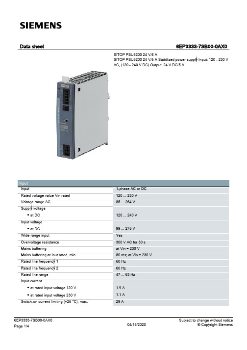
SITOP PSU6200 24 V/5 A SITOP PSU6200 24 V/5 A Stabilized power supply Input: 120 - 230 V AC, (120 - 240 V DC) Output: 24 V DC/5 A
Push-in terminals
L1/+, L2/N/-; PE PushIn for 0.5 ... 4 mm² single-core/finely stranded +1, +2, -1, -2, -3: PushIn for 0.5 ... 2.5 mm² 13, 14 (alarm signal): 1 push-in terminal each for 0.2 ... 1.5 mm² 35 mm 135 mm
6EP3333-7SB00-0AX0 Page 4/4
04/15/2020
Subject to change without notice © Copyright Siemens
6EP3333-7SB00-0AX0 Page 1/4
1-phase AC or DC 120 ... 230 V 85 ... 264 V
120 ... 240 V
99 ... 275 V Yes 300 V AC for 30 s at Vin = 230 V 80 ms; at Vin = 230 V 50 Hz 60 Hz 47 ... 63 Hz
environmental conditions Ambient temperature ● during operation — Note ● during transport ● during storage Humidity class according to EN 60721
同步带技术参数
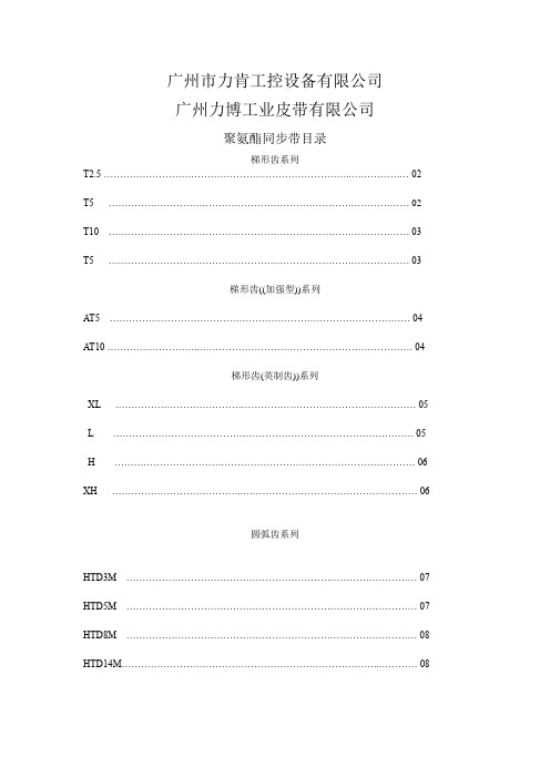
*被广泛使用在输送传动、线性驱动和小功率传动
公差范围
*宽度公差:±0.5 [mm]
*长度公差:±0.5 [mm/m]
*厚度公差:±0.2[mm]
技术参数
宽度[MM]
10
16
25
32
50
75
100
开口带额定负载[N]
350
488
830
1086
1764
2530
3340
接驳带最大负载[N]
*钢丝芯聚氨酯同步带
*梯形齿形,按DIN 7721 T1标准
*最适用于高柔性的驱动应用场合
*被广泛使用在输送传动、线性驱动和小功率传动
公差范围
*宽度公差:±0.5 [mm]
*长度公差:±0.5 [mm/m]
*厚度公差:±0.2[mm]
技术参数
宽度[MM]
10
16
25
32
50
75
100
开口带额定负载[N]
*传递扭矩高,传动精度高
*被广泛使用在线性定位和小功率传动
公差范围
*宽度公差:±0.5 [mm]
*长度公差:±0.5 [mm/m]
*厚度公差:±0.2[mm]
技术参数
宽度[MM]
10
15
25
30
50
开口带额定负载[N]
300
480
780
920
1560
接驳带最大负载[N]
150
240
390
460
780
4600
6160
重量[kg/m]
0.014
0.018
0.022
0.03
BS62LV1600FI55中文资料

BS62LV1600FI55中⽂资料Very Low Power CMOS SRAM 2M X 8 bitBS62LV1600Pb-Free and Green package materials are compliant to RoHSn FEATURESWide V CC operation voltage : 2.4V ~ 5.5V Very low power consumption : V CC = 3.0V Operation current : 46mA (Max.) a t 55ns 2mA (Max.) at 1MHz Standby current : 1.5uA (Typ.) at 25 O C V CC = 5.0V Operation current : 115mA (Max.) a t 55ns 10mA (Max.) a t 1MHz Standby current : 6.0uA (Typ.) at 25O C ? High speed access time : -55 55ns (Max.) at V CC :3.0~5.5V -70 70ns (Max.) at V CC : 2.7~5.5V ? Automatic power down when chip is deselected ? Easy expansion with CE1, CE2 and OE options ? Three state outputs and TTL compatible ? Fully static operation ? Data retention supply voltage as low as 1.5V n DESCRIPTIONThe BS62LV1600 is a high performance, very low power CMOS Static Random Access Memory organized as 2048K by 8 bits and operates form a wide range of 2.4V to 5.5V supply voltage.Advanced CMOS technology and circuit techniques provide both high speed and low power features with typical CMOS standby current of 1.5uA at 3.0V/25O C and maximum access time of 55ns at 3.0V/85O C.Easy memory expansion is provided by an active LOW chip enable (CE1), an active HIGH chip enable (CE2), and active LOW output enable (OE) and three-state output drivers.The BS62LV1600 has an automatic power down feature, reducing the power consumption significantly when chip is deselected. The BS62LV1600 is available in JEDEC standard 44-pin TSOP II and 48-ball BGA package.n POWER CONSUMPTIONPOWER DISSIPATIONSTANDBY(I CCSB1, Max)Operating(I CC , Max)V CC =5.0V V CC =3.0V PRODUCT FAMILYOPERATING TEMPERATUREV CC =5.0V V CC =3.0V1MHz10MHzf Max. 1MHz10MHzf Max.PKG TYPEBS62LV1600EC TSOP II-44 BS62LV1600FC Commercial +0O C to +70O C 50uA 8.0uA 9mA 48mA 113mA 1.5mA 19mA 45mABGA-48-0912 BS62LV1600EITSOP II-44 BS62LV1600FIIndustrial -40O C to +85O C100uA 16uA 10mA 50mA 115mA 2mA 20mA 46mABGA-48-0912n PIN CONFIGURATIONSn BLOCK DIAGRAMBrilliance Semiconductor, Inc. reserves the right to change products and specifications without notice.G H F E D C B A 1 2 3 4 5 6 A9 A11 A10 A19A12 A14 A13 A15 WE NC NC NC DQ7 A17 A16 A7 VSS VCC DQ2 DQ1 DQ6 DQ5 NC A5 OE A3 A0 A6 A4 A1A2CE2 NC NC NCCE1 DQ4 NC 48-ball BGA top view NC NC DQ0 VSS VCC DQ3 NC A18 A20 A8n TRUTH TABLEn ABSOLUTE MAXIMUM RATINGS (1)SYMBOL PARAMETER RATING UNITSV TERM Terminal Voltage withRespect to GND-0.5(2) to 7.0 VT BIAS Temperature UnderBias-40 to +125 O CT STG Storage Temperature -60 to +150 O CP T Power Dissipation 1.0 WI OUT DC Output Current 20 mA1. Stresses greater than those listed under ABSOLUTE MAXIMUM RATINGS may cause permanent damage to the device. This is a stress rating only and functional operation of the device at these or any other conditions above those indicated in the operational sections of this specification is not implied. Exposure to absolute maximum rating conditions for extended periods may affect reliability.2. –2.0V in case of AC pulse width less than 30 ns. n OPERATING RANGERANGAMBIENTTEMPERATUREV CC Commercial 0O C to + 70O C 2.4V ~ 5.5VIndustrial -40O C to + 85O C 2.4V ~ 5.5Vn CAPACITANCE (1) (T A = 25O C, f = 1.0MHz) SYMBOL PAMAMETER CONDITIONS MAX. UNITS C INInputCapacitanceV IN = 0V 10 pFC IOInput/OutputCapacitanceV I/O = 0V 12 pF1. This parameter is guaranteed and not 100% tested.n DC ELECTRICAL CHARACTERISTICS (T A =-40O C to +85OC)1. Typical characteristics are at T A =25O C and not 100% tested.2. Undershoot: -1.0V in case of pulse width less than 20 ns.3. Overshoot: V CC +1.0V in case of pulse width less than 20 ns.4. F MAX =1/t RC.5. I CC(MAX.) is 45mA/113mA at V CC =3.0V/5.0V and T A =70O C.6. I CCSB1(MAX.) is 8.0uA/50uA at V CC =3.0V/5.0V and T A =70O C.n DATA RETENTION CHARACTERISTICS (T A = -40O C to +85OC)1. V CC =1.5V, T A =25O C and not 100% tested.2. t RC = Read Cycle Time.3. I CCRD(Max.) is4.0uA at T A =70O C.n LOW V CC DATA RETENTION WAVEFORM (1) (CE1 Controlled)Data Retention Mode V CCt CDRV CC t RV IHV IHCE1≧V CC - 0.2V V DR ≧1.5V CE1V CCn LOW V CC DATA RETENTION WAVEFORM (2) (CE2 Controlled)n AC TEST CONDITIONS (Test Load and Input/Output Reference)Input Pulse Levels Vcc / 0V Input Rise and Fall Times 1V/ns Input and Output Timing Reference Level 0.5Vcc t CLZ , t OLZ , t CHZ , t OHZ , t WHZ C L = 5pF+1TTL Output LoadOthersC L = 30pF+1TTL1. Including jig and scope capacitance.n KEY TO SWITCHING WAVEFORMSn AC ELECTRICAL CHARACTERISTICS (T A = -40O C to +85OC)READ CYCLECE2 Data Retention Mode V CC t CDR V CC t R V ILV IL V CCV DR ≧1.5V CE2≦0.2V 1 TTL ALL INPUT PULSES→← 90%V CC GND Rise Time : 1V/ns Fall Time : 1V/ns90%→← 10%10%n SWITCHING WAVEFORMS (READ CYCLE)READ CYCLE 1 (1,2,4)READ CYCLE 2 (1,3,4)READ CYCLE 3 (1, 4)NOTES:1. WE is high in read Cycle.2. Device is continuously selected when CE1 = V IL and CE2= V IH .3. Address valid prior to or coincident with CE1 transition low and/or CE2 transition high.4. OE = V IL .5. Transition is measured ± 500mV from steady state with C L = 5pF. The parameter is guaranteed but not 100% tested. t RC t OHt AA D OUT ADDRESS t OHD OUTCE2 CE1D OUTCE2 CE1 OE ADDRESSn AC ELECTRICAL CHARACTERISTICS (T A = -40OC to +85OC)WRITE CYCLEn SWITCHING WAVEFORMS (WRITE CYCLE)WRITE CYCLE 1 (1)t WCt WR1(3)t CW(11)t CW(11)t WP(2)t AWt OHZ(4,10)t AS t WR2(3)t DHt DWD IND OUTWECE2CE1OEADDRESS(5)(5)WRITE CYCLE 2 (1,6)NOTES:1. WE must be high during address transitions.2. The internal write time of the memory is defined by the overlap of CE1 and CE2 active and WE low. All signals must be active to initiate a write and any one signal can terminate a write by going inactive. The data input setup and hold timing should be referenced to the second transition edge of the signal that terminates the write.3. t WR is measured from the earlier of CE1 or WE going high or CE2 going low at the end of write cycle.4. During this period, DQ pins are in the output state so that the input signals of opposite phase to the outputs must not be applied.5. If the CE1 low transition or the CE2 high transition occurs simultaneously with the WE low transitions or after the WE transition, output remain in a high impedance state.6. OE is continuously low (OE = V IL ).7. D OUT is the same phase of write data of this write cycle. 8. D OUT is the read data of next address.9. If CE1 is low and CE2 is high during this period, DQ pins are in the output state. Then the data input signals of opposite phase to the outputs must not be applied to them. 10. T ransition is measured ± 500mV from steady state with C L = 5pF. The parameter is guaranteed but not 100% tested. 11. t CW is measured from the later of CE1 going low or CE2 going high to the end of write.D IND OUTWE CE2 CE1ADDRESSn ORDERING INFORMATIONBSI (Brilliance Semiconductor Inc.) assumes no responsibility for the application or use of any product or circuit described herein. BSI does not authorize its products for use as critical components in any application in which the failure of the BSI product may be expected to result in significant injury or death, including life-support systems and critical medical instruments.n PACKAGE DIMENSIONSTSOP II-44n PACKAGE DIMENSIONS (continued)3: SYMBOL "N" IS THE NUMBER OF SOLDER BALLS.1: CONTROLLING DIMENSIONS ARE IN MILLIMETERS. 2: PIN#1 DOT MARKING BY LASER OR PAD PRINT.N EDNOTES:4812.09.0E1D1e3.755.250.75 48 mini-BGA (9mm x 12mm)n Revision HistoryRevision No. History Draft Date Remark2.2 Add Icc1 characteristic parameter Jan. 13, 2006Improve Iccsb1 spec.I-grade from 220uA to 100uA at 5.0V20uA to 16uA at 3.0VC-grade from 110uA to 50uA at 5.0V10uA to 8.0uA at 3.0V2.3 Change I-grade operation temperature range May. 25, 2006 - from –25O C to –40O C。
IC65系列小型断路器
12
额定工作频率(Hz)
50/60
额定冲击耐受电压(kV) Uimp
6
额定短路能力Icn,230V/400V
6kA
(IEC/EN 60898)
额定极限短路分断能力 Icu, 230V/400V (IEC/EN 60947-2)
额定运行短路分断能力 Ics, 230V/400V (IEC/EN 60947-2)
目前,施耐德电气在中国共建立53个办事处,28家工厂,7个物流中心,1 个研修学院,3个全球研 发中心,1000多名研发工程师,1 个实验室,1 所能源大学,700多家分销商和遍布全国的销售网 络。施耐德电气中国目前员工数近28,000人。通过与合作伙伴以及大量经销商的合作,施耐德电气
为中国创造了成千上万个就业机会。
施耐德电气
能效管理平台
凭借其对五大市场的深刻了解、对集团客户的悉心关爱,以及在能效管理领域的丰富经验,施耐德电 气从一个优秀的产品和设备供应商逐步成长为整体解决方案提供商。今年,施耐德电气首次集成其在 建筑楼宇、IT、安防、电力及工业过程和设备等五大领域的专业技术和经验,将其高质量的产品和解 决方案融合在一个统一的架构下,通过标准的界面为各行业客户提供一个开放、透明、节能、高效的
控制类产品
RCA远程控制附件 ..................................................................................................... 55 ARA自动重合控制附件 ............................................................................................60 Reflex iC60集成控制断路器...................................................................................66 Acti 9 Smartlink 智能接口单元 .............................................................................. 72
CS5460A中文数据手册
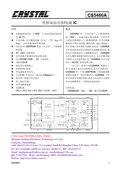
Cirrus Lohai benhong Electronics Technologies Co.,Ltd Contactee: Zhoubenhong Addr: Rm1101,No 47,Lane 1111,Lianhua South Rd,Shanghai China, P.R.China. 201100
2.综述 ..................................................................................................................................................... 12 2.1 操作原理 ..................................................................................................................................... 12 2.1.1 ÄÓ 调制器 .......................................................................................................................... 12 2.1.2 高速数字低通滤波器......................................................................................................... 12 2.1.3 数字补偿滤波器 ................................................................................................................ 12 2.1.4 数字高通滤波器 ................................................................................................................ 12 2.1.5 总的滤波器响应 ................................................................................................................ 12 2.1.6 增益及 DC 偏移量调整 ..................................................................................................... 12 2.1.7 有功能量及有效值计算 ..................................................................................................... 13 2.2 执行测量 ..................................................................................................................................... 13 2.2.1 CS5460A 线性性能 ........................................................................................................... 14 2.2.2 单计算周期(C=0 ) ....................................................................................................... 14 2.2.3 连续计算周期(C=1 ).................................................................................................... 15 2.3 基本应用电路结构....................................................................................................................... 15
老雷电子有限公司 LTS6 串行输入到分析输出传输器说明书

LAUREL ELECTRONICS, INC.LTS6 Serial-to-Analog Converter and DIN Rail TransmitterFeatures•Converts serial data to a isolated, scaled 4-20 mA or 0-10V transmitter output•Accepts an RS232 or RS485 serial data, half or full duplex, isolated•Supports Modbus RTU, Modbus ASCII, or Laurel ASCII protocols•Able to retrieve data from long character strings•Serial data rates from 300 to 9,600 baud•Analog transmitter output, isolated•Analog resolution 0.0015% of span (16 bits), accuracy ±0.02% of span•Dual solid state relays for alarm or control, isolated•Universal AC power, 85-264 Vac, or low voltage power, 10-48 Vdc or 12-32 Vac•-X extended operating temperature option for -40°C to 70°CDescriptionThe Laureate LTS6 serial input to analog output transmitteraccepts RS232 or RS485 serial data using the Modbus protocol,Laurel ASCII protocol, or direct ASCII characters, and convertsthis data to an isolated, scalable 4-20 mA, 0-20 mA or 0-10Vanalog output. The unit is housed in transmitter case which isonly 22.5 mm (0.89") thick and fits on a 35 mm DIN rail. It isnormally powered by AC (85-264 Vac), but can optionally bepowered by low voltage AC or DC. All electrical connections arevia detachable screw-clamp plugs.Features include:•Analog transmitter output, 16-bit, scalable and isolated.User selectable 4-20 mA, 0-20 mA or 0-10V levels. A 16-bitdigital-to-analog converter provides ultra-fine resolution of0.0015% and accuracy better than 0.02% of output span.Output isolation from signal, power and serial communicationgrounds is provided by a separate on-board transmitter powersupply, thereby eliminating potential problems caused byground loops. The supply can drive 20 mA into a 500Ω (orlower) load for 10V compliance, or 10V into 5 kΩ (or higher)load for 2 mA compliance.•Serial communications input, isolated. User selectableRS232 or RS485, half or full duplex, Modbus protocol, LaurelASCII protocol, or ASCII characters at data rates up to 19200bps. The RS232 interface is suitable for short cable runs andpoint-to-point communications. The RS485 interface is com-pliant with the EIA/TIA-485 standard and supports multipleaddressable devices on the same data line using the Modbusprotocol or Laurel ASCII Protocol. Modbus implementation isfully compliant with Modbus over Serial Line Specification V1.0(2002) in RTU or ASCII, half-duplex or full-duplex operation,with up to 247 digital addresses.•Ability to extract readings from long ASCII data strings.You can specify character positions, start and stop ASCIIcharacters, how many characters to skip, and how manycharacters to process. Slave operation requires connection toa master. Not applicable to the Modbus protocol.•Dual solid state relays for control or alarm. Rated 120 mAat 130 Vac or 170 Vdc, isolated.•Universal AC power supply for 85-264 Vac.•Optional low voltage power, 10-48 Vdc or 12-32 Vac.Easy Transmitter programming is via Laurel's InstrumentSetup Software, which runs on a PC under MS Windows. Thissoftware can be downloaded from Laurel’s website at no charge.The required cable from the transmitters to a PC com port isavailable from Laurel (P/N CBL04).SpecificationsSerial Communications(standard) Signal Types Data RatesOutput Isolation Serial Protocols Modbus ModesModbus Compliance Digital Addressing RS232 or RS485 (half or full duplex) 300, 600, 1200, 2400, 4800, 9600 baud250V rms working, 2.3 kV rms per 1 min test Modbus RTU, Modbus ASCII, Laurel ASCII RTU or ASCIIModbus over Serial Line Specification V1.0 (2002) 247 Modbus addresses.Up to 32 devices on an RS485 line without a repeater.Analog Output (standard) Output LevelsCompliance, 4-20 mA Compliance, 0-10V Output Resolution Output Accuracy Output Update Rate Output Isolation4-20 mA, 0-20 mA, 0-10 Vdc (selectable) 10V ( 0-500Ω load ) 2 mA ( 5 kΩ load ) 16 bits (65,536 steps) 0.02% of output spanDetermined by input data rate250V rms working, 2.3 kV rms per 1 minute test Dual Relay Output (standard) Relay Type Load Rating Two solid state relays, SPST, normally open, Form A 120 mA at 140 Vac or 180 VdcPower Input Standard Power Low Power Option Power Frequency Power IsolationPower Consumption 85-264 Vac or 90-300 Vdc 10-48 Vdc or 12-32 Vac DC or 47-63 Hz250V rms working, 2.3 kV rms per 1 min test 2W typical, 3W with max excitation outputMechanicalDimensions MountingElectrical Connections 129 x 104 x 22.5 mm case 35 mm rail per DIN EN 50022 Plug-in screw-clamp connectorsEnvironmental Operating Temperature Storage Temperature Relative Humidity Cooling Required0°C to 55°C standard, -40°C to 70°C with -X option -40°C to 85°C95% at 40°C, non-condensingMount transmitters with ventilation holes at top and bottom. Leave 6 mm (1/4") between transmitters, or force air with a fan.PinoutMechanicalOrdering GuideCreate a model a model number in this format: LTS60-X, CBL02, CBL04Transmitter Type LTS6 Serial input transmitter, 4-20 mA, 0-20 mA or 0-10V output. Power 0 85-264 Vac or 90-300 Vdc1 Isolated 12-32 Vac or 10-48 VdcOptions & Accessories-X Extended operating temperature -40°C to 70°C CBL04 RS-232 cable, LTS6 to computer or USB adapter CBL02 USB to RS-232 cable adapter。
UT60H数字万用表说明书
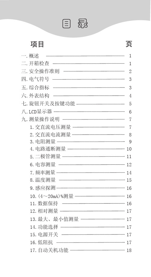
5.二极管测量 (见图 7)
(图 7)
11
UT60H 使用说明书
1) 将红表笔插入“Ω” 插孔,黑表笔插入“COM” 插孔。红表笔极性为 “+”,黑表笔极性为 “-”。
2) 将功能开关置于 “Ω
” 测量档,按
SELECT 键选择二极管测量,红表笔接到被测
二极管的正极,黑表笔接到二极管的负极。
3) 从显示器上直接读取被测二极管的近似正向
输入保护电压说明 2.μA mA 输入端子设有保险丝:(CE) 0.5A 250V
快熔式保险丝Φ5x20mm 3.A 输入端子设有保险丝:(CE) 10A 250V 快熔式
保险丝Φ5x20mm 4.显示:全字符及模拟条,最大读数为 39999,每秒
约更新 2~3 次。 5.量程:自动 6.极性显示:自动 7.过量程提示:显 OL〔在(4~20mA)% 量程中显 LO
Low imp.200kΩ
POWER
电路通断测量 电容测量 频率测量 温度测量
(4~20mA) 百分比测量 感应探测 AC 50~400V 交流信号 0.1μA~4000μA 交直流电流测量 0.01mA~400.0mA 交直流电流测量 0.01A~10.00A 交直流电流测量
200kΩ低阻抗选择按键
本使用说明书包括有关的安全信息和警告提 示等,请仔细阅读有关内容并严格遵守所有的警 告和注意事项。
二.开箱检查 打开包装盒取出仪表,请仔细检查下列附件
是否缺少或损坏,如发现有任何一项缺少或损坏, 请即与你的供应商联系。
UT65L1616BS-70LLI中文资料
UTRON TECHNOLOGY INC. 1F, No. 11, R&D Rd. II, Science-Based Industrial Park, Hsinchu, Taiwan, R. O. C. TEL: 886-3-5777882 FAX: 886-3-5777919
P80080
4
UTRON
A
CE
LB I/O9
I/O10
OE UB
I/O11 I/O12 I/O13
A0 A3 A5 A17 Vss A14
A1 A4 A6 A7 A16 A15 A13 A10
A2 CE I/O2 I/O4 I/O5 I/O6 WE A11
ZZ I/O1 I/O3 Vcc Vss I/O7 I/O8
NC
OE WE LB UB
ZZ
B
CONTROL CIRCUIT
C D E F G H
Vss
Vccq
I/O15 I/O16
I/O14
A19 A12 A8 A9A181 Nhomakorabea2
3
4
5
6
TFBGA
UTRON TECHNOLOGY INC. 1F, No. 11, R&D Rd. II, Science-Based Industrial Park, Hsinchu, Taiwan, R. O. C. TEL: 886-3-5777882 FAX: 886-3-5777919
FUNCTIONAL BLOCK DIAGRAM
A0-A19 Vcc Vccq Vss I/O1-I/O8 Lower Byte I/O9-I/O16 Upper Byte DECODER 1M × 16 MEMORY ARRAY
2N60L中文资料
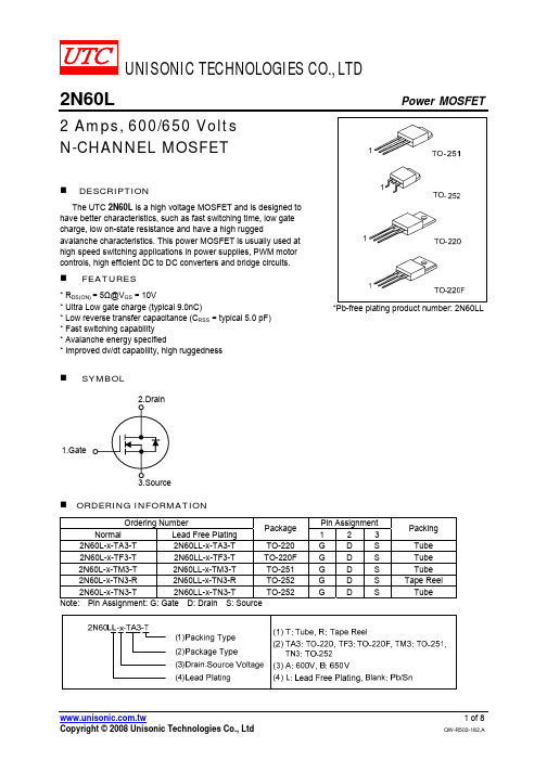
UNISONIC TECHNOLOGIES CO., LTD2N60L Power MOSFET2 Amps, 600/650 VoltsN-CHANNEL MOSFETDESCRIPTIONThe UTC 2N60L is a high voltage MOSFET and is designed tohave better characteristics, such as fast switching time, low gatecharge, low on-state resistance and have a high ruggedavalanche characteristics. This power MOSFET is usually used athigh speed switching applications in power supplies, PWM motorcontrols, high efficient DC to DC converters and bridge circuits.FEATURES* R DS(ON) = 5Ω@V GS = 10V* Ultra Low gate charge (typical 9.0nC)* Low reverse transfer capacitance (C RSS = typical 5.0 pF)* Fast switching capability* Avalanche energy specified* Improved dv/dt capability, high ruggednessSYMBOL1.Gate*Pb-free plating product number: 2N60LLORDERING INFORMATIONOrdering Number Pin AssignmentNormal Lead Free PlatingPackage1 2 3Packing 2N60L-x-TA3-T 2N60LL-x-TA3-T TO-220GDS Tube 2N60L-x-TF3-T 2N60LL-x-TF3-TTO-220FGDS Tube 2N60L-x-TM3-T 2N60LL-x-TM3-T TO-251GDS Tube 2N60L-x-TN3-R 2N60LL-x-TN3-R TO-252GDSTapeReel 2N60L-x-TN3-T 2N60LL-x-TN3-T TO-252GDS Tube Note: Pin Assignment: G: Gate D: Drain S: SourceABSOLUTE MAXIMUM RATINGS (T C = 25℃, unless otherwise specified)PARAMETER SYMBOL RATINGS UNIT2N60L-A 600 VDrain-Source Voltage 2N60L-B V DSS650 VGate-Source Voltage V GSS ±30 V Avalanche Current (Note 1) I AR 2.0 AT C = 25°C 2.0 ADrain Current Continuous T C = 100°C I D1.26 ADrain Current Pulsed (Note 1) I DP 8.0 ASingle Pulsed (Note 2)E AS 140 mJAvalanche EnergyRepetitive (Note 1) E AR 4.5 mJPeak Diode Recovery dv/dt (Note 3) dv/dt 4.5 V/nsTO-220 32 W TO-220F 9 WTO-251 25 W Total Power Dissipation TO-252 P D20 WJunction Temperature T J +150 Operating Temperature T OPR -55 ~ +150 Storage Temperature T STG -55 ~ +150Note: Absolute maximum ratings are those values beyond which the device could be permanently damaged.Absolute maximum ratings are stress ratings only and functional device operation is not implied.THERMAL DATAPARAMETER PACKAGE SYMBOL RATINGS UNITTO-251 65 TO-252 58TO-220 43 Thermal Resistance Junction-Ambient TO-220F θJA38TO-251 5 TO-252 6TO-220 4 Thermal Resistance Junction-Case TO-220F θJc12/WELECTRICAL CHARACTERISTICS (T J =25℃, unless otherwise specified)PARAMETER SYMBOL TEST CONDITIONS MIN TYP MAX UNITOFF CHARACTERISTICS2N60L-A 600 VDrain-Source Breakdown Voltage 2N60L-B BV DSS V GS = 0V, I D = 250µA650 VDrain-Source Leakage Current I DSS V DS = 600V, V GS = 0V 10µAForward V GS = 30V, V DS = 0V 100nAGate-Source Leakage Current Reverse I GSSV GS = -30V, V DS = 0V-100nA Breakdown Voltage Temperature Coefficient BV DSS /T J I D = 250 µA, Referenced to25°C 0.4 V/ON CHARACTERISTICS Gate Threshold Voltage V GS(TH) V DS = V GS , I D = 250µA 2.0 4.0V Static Drain-Source On-State Resistance R DS(ON) V GS = 10V, I D =1A 3.8 5 Ω DYNAMIC CHARACTERISTICS Input Capacitance C ISS 270 350pFOutput Capacitance C OSS 40 50pFReverse Transfer Capacitance C RSS V DS =25V, V GS =0V, f =1MHz 5 7 pFELECTRICAL CHARACTERISTICS(Cont.)PARAMETER SYMBOL TEST CONDITIONS MIN TYP MAX UNITSWITCHING CHARACTERISTICS Turn-On Delay Time t D (ON) 10 30ns Turn-On Rise Time t R 25 60ns Turn-Off Delay Time t D(OFF) 20 50nsTurn-Off Fall Time t FV DD =300V, I D =2.4A, R G =25Ω(Note 4, 5) 25 60ns Total Gate Charge Q G 9.0 11nCGate-Source Charge Q GS 1.6 nC Gate-Drain Charge Q GD V DS =480V, V GS =10V, I D =2.4A(Note , 5) 4.3 nC DRAIN-SOURCE DIODE CHARACTERISTICS Drain-Source Diode Forward Voltage V SD V GS = 0 V, I SD = 2.0 A 1.4V Continuous Drain-Source Current I SD 2.0 A Pulsed Drain-Source Current I SM 8.0 A Reverse Recovery Time t RR 180 nsReverse Recovery Charge Q RR V GS = 0 V, I SD = 2.4A, di/dt = 100 A/µs (Note4) 0.72 µCNote: 1. Repetitive Rating : Pulse width limited by T J2. L=64mH, I AS =2.0A, V DD =50V, R G =25 Ω, Starting T J = 25°C3. I SD ≤ 2.4A, di/dt ≤200A/µs, V DD ≤ BV DSS , Starting T J = 25°C4. Pulse Test: Pulse width ≤ 300µs, Duty cycle ≤ 2%5. Essentially independent of operating temperatureTEST CIRCUITS AND WAVEFORMSV DDV GS (Driver)I SD (D.U.T.)Body DiodeForward Voltage DropV DS (D.U.T.)Fig. 1A Peak Diode Recovery dv/dt Test CircuitFig. 1B Peak Diode Recovery dv/dt WaveformsTEST CIRCUITS AND WAVEFORMS(Cont.)Fig. 2A Switching Test Circuit Fig. 2B Switching WaveformsFig. 3A Gate Charge Test Circuit Fig. 3B Gate Charge WaveformFig. 4A Unclamped Inductive Switching Test Circuit Fig. 4B Unclamped Inductive Switching WaveformsTYPICAL CHARACTERISTICSC a p a c i t a n c e (p F )G a t e -S o u r c e V o l t a g e , V G S (V )TYPICAL CHARACTERISTICS(Cont.)D r a i n -S o u r c e B r e a k d o w n V o l t a g e , V D S S (N o r m a l i z e d )D r a i n -S o u r c e O n -R e s i s t a n c e , R D S (O N ) (N o r m a l i z e d )D r a i n C u r r e n t , I D (A )D r a i n C u r r e n t , I D (A )。
线材额定电压 温度
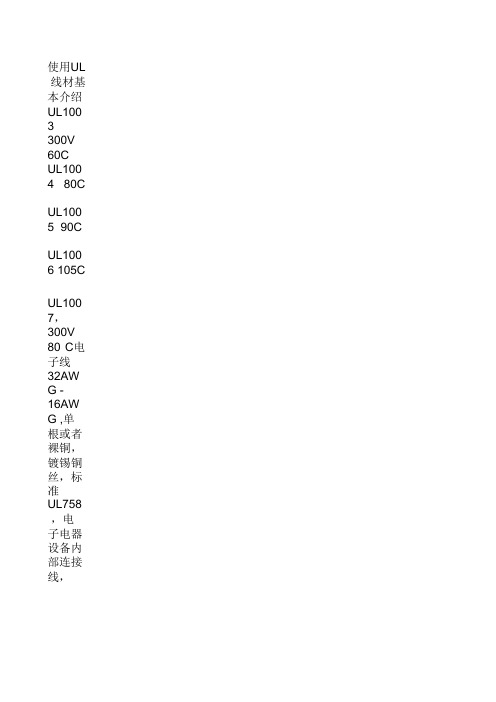
UL112 7 105C UL119 5 300V 80C
UL119 9 600V 200C 单芯特 氟龙 线, 304AWG 外被材 质 PTFE
UL121 3 105C 3616AW G 单芯 特氟龙 线,外 被材质 FEP
UL122 7 105C 3210AW G 单芯 特氟龙 线,外 被材质 FEP/P TFE UL123 2 600V 105C
UL127 5 600V 105 C UL128 3 600V 105C UL128 4 600V 105C UL131 6 699 105C UL131 7 600V 105C UL131 8 600V 105C UL131 9 600V 105C UL132 0 600V 105C UL132 1 600V 105C
UL163 5 80C
UL163 7 30V 90C UL163 8 300V 90C UL164 0 30V 80C UL164 2 300V 80C UL164 3 300V 150C
UL164 4 600V 150C 304AWG 单芯特 氟龙 线,外 被材质 ETFE UL164 5 600V 105C UL164 5 90V 105C
UL110 8 300V 80C UL110 9 300V 90C UL111 0 300V 105C UL111 2 300V 80C
UL111 3 600V 60C UL115 0 300V 60C UL115 3 300V 60C
UL116 4 300V 150C 3210AW G 单芯 特氟龙 线,外 被材质 PTFE UL116 7 600V 80C UL117 4 300V 80C UL117 6 80C
UL168 6 105C 3220AW G 单芯 特氟龙 线,外 被材质 ECTFE
MT-GSM168无线转发器产品说明书
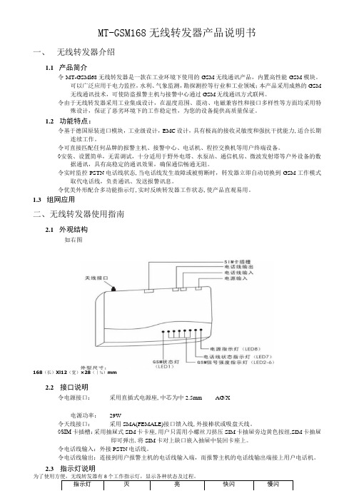
MT-GSM168无线转发器产品说明书一、无线转发器介绍1.1产品简介令MT-GSMl68无线转发器是一款在工业环境下使用的GSM无线通讯产品,内置高性能GSM模块。
可以广泛应用于电力监控,水利、气象监测,勘探测控等行业和工业领域;本产品采用成熟的GSM无线通讯技术,可使防盗报警主机与接警中心通过GSM无线通讯方式联网。
令由于无线转发器采用工业集成设计,在温度范围、震动、电磁兼容性和接口多样性等方面均采用特殊设计,保证了恶劣环境下的工作稳定性,为您的设备提供高质量保证。
1.2功能特点:令基于德国原装进口模块,工业级设计,EMC设计,具有极高的接收灵敏度和强抗干扰能力,适合长期连续工作。
令可直接匹配任何品牌的报警主机、接警中心、电话机、程控交换机等用户终端设备。
◊安装、设置简单,无需调试,十分适用于野外电塔、水泵站、通信机房、微波发射塔等户外设备的数据通讯,具有高稳定的通讯效果,确保通信畅通无阻。
令实时监控PSTN电话线状态,当电话线发生故障或被剪断时,转发器立即自动切换到GSM工作模式取代电话线,负责通讯、发送报警讯息。
令优美外形配合多功能指示灯,实时反映转发器工作状态,使产品直观易用。
1.3组网应用二、无线转发器使用指南2.1外观结构如右图168(长)Xl12(宽)×28(∣⅛)mm2.2接口说明令电源接口:采用直插式电源座,中芯为中2.5mm AG/X电源功率:29W令天线接口:采用SMA(FEMALE)接口馈入线,外接棒状或吸盘天线。
◊SIM卡插槽:采用抽屉式SIM卡卡座,用户只需用小螺丝刀挤压SIM卡抽屉旁边黄色按纽,SIM卡抽屉即可弹出.将SIM卡对上缺口嵌入抽屉中装回卡座上。
令电话线输入:外接PSTN电话线。
令电话线输出:连接到用户报警主机的电话线输入端,而报警主机的电话线输出端接上用户电话机。
2.3指示灯说明注:3S灭2.4使用说明令正确安装后通上电源,待LED灯自检结束后,GSM状态灯慢闪,转发器已取得网络信号,可以正常工作。
德力西电气 User manual of 96L、72L frequency meter-EN说明书

96L, 72L Mounted Analog Indicating Frequency Measuring InstrumentUser ManualStandard: GB/T 7676Please carefully read this User Manual before installing andoperating the product, and keep this manual properly for futurereference1 Scope of ApplicationThe product is suitable for the measurement of frequencies in AC circuits. In addition to separate use, it is primarily used as a matching instrument panel for the high-voltage and low-voltage switchgear cabinets, power cabinets, and control cabinets of various AC transmission and distribution systems.2. Structure FeaturesThe product is composed of a magnetoelectric measuring mechanism and a measuring circuit, and the measuring mechanism and the measuring circuit are of the integral structure. The dials adopt the plug-in structure, and all of them are printed dials.3 Working PrincipleThe measured frequency is converted into a DC current signal acceptable by the measuring mechanism through the measuring circuit, and the turning moment is generated by the interaction between the magnetic field generated when the current passes through the movable coil and the magnetic field of the fixed permanent magnet to make the movable coil drive the pointer deflects. When the reaction moment of the balance spring is balanced, the pointer indicates the measured value on the dial plate.4. Main Technical ParametersThe performance of the instrument complies with the GB/T 7676.1 Direct acting indicating analogue electrical measuring instruments and its accessories –Definitions and general requirements common to all parts and the GB/T 7676.4 Direct acting indicating analogue electrical measuring instruments and its accessories –Special requirements for frequency meters.4.1 Accuracy grade: 1.0.4.2 Response time: ≤4s.4.3 The range is listed in Table 1.Table 1: Frequency meter rangeUnit Range Voltage of the measured circuit Connection methodHz 45~5545~6555~65100V, 220V, 380V Direct connection4.4 Pointer deflection angle: 90°4.5 Withstand voltage test: Subject to the test with frequency 50Hz, voltage 2kV, current 5mA, and duration for 1 minute, there is no breakdown or flashover.4.6 Working conditions4.6.1 Operating temperature range: -5°C~ 45 °C.4.6.2 Instrument housing protection grade: IP51.4.6.3 Working position: The dial is installed vertically when use.5. Installation and Use5.1 Please read the product instructions carefully before installation and use.5.2 Please install the instrument in the control cabinets such as power distribution cabinet and power distribution box though the clamping parts or fasteners firmly and reliably.5.3 Please connect the wire properly according to the wiring diagram.5.4 The wiring connection principle is illustrated Fig. 1:LoadFig. 15.5 When connecting the instrument cable, the copper wire or copper lug is required. If the multi-strand copper is used, its ends of wire shall be twisted and wound firmly, and then connected to the wiring terminal of the instrument after subject to the tinning treatment. The instrument shall be wired firmly and reliably.5.6 When the instrument is installed and used in an area where there are more thunderstorms, the corresponding lightning protection measures shall be taken to avoid damage to the instrument by lightning strikes.5.7 Before power-on and use, please check whether the instrument is installed firmly and whether the wiring is connected properly, firmly, and reliably.5.8 The instrument must be deenergized during the installation and maintenance to prevent damage to the product and the personal electric shock accidents.6. Packaging, Transportation and Storage6.1 The outer packing box of the instrument or accessories shall be attached with the graphic mark of packaging, storage and transportation according to GB/T 191.6.2 During the transfer, transportation, loading, and unloading of the instrument, please carefully handle it gently, do not throw it, and prevent severe vibration and impact strictly.6.3 If the instrument and accessories are not packaged, they shall be stored in an indoor room where the ambient temperature is -5°C ~ 45°C, the relative humidity is 85% and below, and there are no harmful substances sufficient to cause corrosion in the air.7. Outline and installation dimensions7.1 The outline drawings are illustrated in Fig. 2.7.2 The outline and installation dimensions are listed in Table 2.Fig. 2 Outline drawings8 Company’s commitmentThe "Three guarantees" service shall be provided by the company for abnormal operation due to the poor manufacturing quality of the product under the conditions of the normal storage, transport, maintenance, and operation within the 24 months from the date of production.9 Attached with the productAccessories package.Certificate.User manual.CertificateThis product passes the inspection according to the standardGB/T7676, and is allowed to be shipped.Inspector: Check 07Inspection date: See the label on the inner boxDELIXI GROUP INSTRUMENTS & METERS CO., LTD. Manufacturer: Delixi Group Instruments & Meters Co., Ltd.Address: Delixi Industrial Park, Liushi Town, Yueqing City, ZhejiangTel: (86-577) 6177 8228 P.C.: 325604Fax: (86-577) 6177 8218Customer service hotline: 400-826-80080DLX.463.8089V1.4The second edition of this user manual was issued in Oct. 2021。
UL线材基本介绍
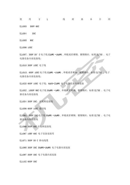
使用U L线材基本介绍UL1003 300V 60CUL1004 80CUL1005 90CUL1006 105CUL1067 10KV 60C 电子设备连接用UL1071 300V 80 C 移动线缆UL1095 300V 80C 30AWG-16AWG 电子电器内部连接UL1097 300V 80C 电子电器内部连接UL1102 600V 80CUL1107 300V 60C,30-16AWG 同轴电缆。
电子电器内部连接线UL1108 300V 80CUL1109 300V 90CUL1110 300V 105CUL1112 300V 80CUL1199UL1208 300V 80CUL1126UL1127 105CUL1195 300V 80CUL1199 600V 200C 单芯特氟龙线,30-4AWG 外被材质PTFE UL1213 105C 36-16AWG 单芯特氟龙线,外被材质FEPUL1227 105C 32-10AWG 单芯特氟龙线,外被材质FEP/PTFE UL1232 600V 105CUL1275 600V 105 CUL1338 125V 105C 1-4AWG 单芯特氟龙线,外被材质FEP UL1353 300V 60CUL1354 300V 80C,同轴线,家电内部连接线UL1355 200CUL1365 300V 60C,同轴线30-16AWG 电子电器内部连接线UL1371 105C 36-6AWG 单芯特氟龙线,外被材质PVDF UL1375 30V 80CUL1380 300V 80CUL1387 300V 60CUL1419 105CUL1481UL1486 300V 105CUL1489 60CUL1490 60CUL1493 300V 80CUL1494 300 80CUL1494 300V 80CUL1497 300V 80CUL1500 600V 105CUL1503 150V 80CUL1523 105C 32-20AWG 单芯特氟龙线,外被材质ETFE UL1524UL1533 80C 单芯屏蔽线缆。
IP65、IP68等防护等级说明
I P65、I P68等防护等级说明(总6页)-CAL-FENGHAI.-(YICAI)-Company One1-CAL-本页仅作为文档封面,使用请直接删除IP65,IP68等防护等级说明IP(INGRESS PROTECTION)防护等级系统是由IEC(INTERNATIONAL ELECTROTECHNICAL COMMISSION)所起草。
将电器依其防尘防湿气之特性加以分级。
这里所指的外物含工具,人的手指等均不可接触到电器内之带电部分,以免触电。
IP防护等级是由两个数字所组成,第1个数字表示灯具离尘、防止外物侵入的等级,第2个数字表示灯具防湿气、防水侵入的密闭程度,数字越大表示其防护等级越高。
两个标示数字所表示的防护等级如表一及表二所示:表一:数字防护范围说明0无防护对外界的人或物无特殊的防护1防止大于50mm的固体外物侵入防止人体(如手掌)因意外而接触到电器内部的零件,防止较大尺寸(直径大于50mm)的外物侵入2防止大于12.5mm的固体外物侵入防止人的手指接触到电器内部的零件,防止中等尺寸(直径大于12.5mm)的外物侵入3防止大于2.5mm的固体外物侵入防止直径或厚度大于12.5mm的工具、电线及类似的小型外物侵入而接触到电器内部的零件4防止大于1.0mm的固体外物侵入防止直径或厚度大于1.0mm的工具、电线及类似的小型外物侵入而接触到电器内部的零件5防止外物及灰尘完全防止外物侵入,虽不能完全防止灰尘侵入,但灰尘的侵入量不会影响电器的正常运作6防止外物及灰尘完全防止外物及灰尘侵入表二:第二个标示特性号码(数字)所指的防护程度数字防护范围说明0无防护对水或湿气无特殊的防护1防止水滴侵入垂直落下的水滴(如凝结水)不会对电器造成损坏2倾斜15度时,仍可防止水滴侵入当电器由垂直倾斜至15度时,滴水不会对电器造成损坏3防止喷洒的水侵入防雨或防止与垂直的夹角小于60度的方向所喷洒的水侵入电器而造成损坏4防止飞溅的水侵入防止各个方向飞溅而来的水侵入电器而造成损坏5防止喷射的水侵入防止来自各个方向飞由喷嘴射出的水侵入电器而造成损坏6防止大浪侵入装设于甲板上的电器,可防止因大浪的侵袭而造成的损坏7防止浸水时水的侵入电器浸在水中一定时间或水压在一定的标准以下,可确保不因浸水而造成损坏8防止沉没时水的侵电器无限期沉没在指定的水压下,可确保不因浸水而造成损入坏附加字母:防止接近危险部件A 手背B 手指C 工具D 金属线补充字母:专门补充的信息H 高压设备M 做防水试验时试样运行S 做防水试验时试样静止W 气候条件- 防水试验1、范围防水试验包括第二位特征数字为1至8,即防护等级代码为IPX1至IPX8。
brand:Luxtron、产品名:I652、型号:I652说明书
1meter 1.4mm OD
Your local Luxtron representative is:
On/Off Switch 24VDC Power Adapter Port
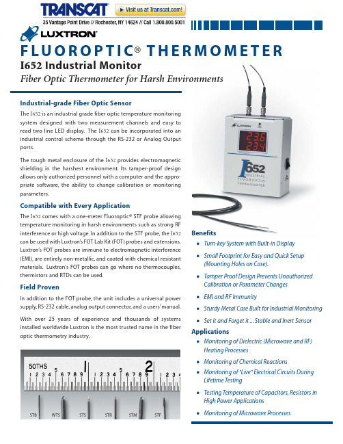
1 meter length STF probe standard. Longer lengths are available upon request. Unit can also be used with other FOT Lab Kit probes and extensions.
Repeatability (Precision) 0.5OC RMS @ 8 samples per measurement
Output Resolution
0.1OC
Measurement Rate
1 to 4 Hz per channel, configurable
Output Format
oC
Compatible with Every Application
The I652 comes with a one-meter Fluoroptic® STF probe allowing temperature monitoring in harsh environments such as strong RF interference or high voltage. In addition to the STF probe, the I652 can be used with Luxtron’s FOT Lab Kit (FOT) probes and extensions. Luxtron’s FOT probes are immune to electromagnetic interference (EMI), are entirely non-metallic, and coated with chemical resistant materials. Luxtron's FOT probes can go where no thermocouples, thermistors and RTDs can be used.
- 1、下载文档前请自行甄别文档内容的完整性,平台不提供额外的编辑、内容补充、找答案等附加服务。
- 2、"仅部分预览"的文档,不可在线预览部分如存在完整性等问题,可反馈申请退款(可完整预览的文档不适用该条件!)。
- 3、如文档侵犯您的权益,请联系客服反馈,我们会尽快为您处理(人工客服工作时间:9:00-18:30)。
B
OE WE LB UB
ZZ
CONTROL CIRCUIT
C D E F G H
Vss
Vccq
I/O15 I/O16
I/O14
NC A8
A18
1
2
3
4
5
6
TFBGA
UTRON TECHNOLOGY INC. 1F, No. 11, R&D Rd. II, Science-Based Industrial Park, Hsinchu, Taiwan, R. O. C. TEL: 886-3-5777882 FAX: 886-3-5777919
Rev. 1.1
512K X 16 BITS LOW POWER PSEUDO SRAM
GENERAL DESCRIPTION
UT65L168(E)/UT65L168(I)
The UT65L168 is a 8,388,608-bit CMOS random access memory organized as 524,288 words by 16 bits. It is fabricated using PSEUDO SRAM techniques, yields high-density and low power consumption device. The UT65L168 is design for upper and low byte access by data byte control ( UB 、 LB ).It has low power modes by using control pin ZZ .
PIN DESCRIPTION
SYMBOL A0 - A18 I/O1 - I/O16 CE
WE OE LB UB ZZ VCC Vccq VSS NC
DESCRIPTION Address Inputs Data Inputs/Outputs Chip enable Input Write Enable Input Output Enable Input Lower Byte Control Upper Byte Control Low Power Modes Core Power I/O power Ground No Connection
COLUMN I/O
A
CE
LB I/O9
I/O10
OE UB
I/O11 I/O12 I/O13
A0 A3 A5 A17 Vss A14 A12 A9
A1 A4 A6 A7 A16 A15 A13 A10
A2 CE I/O2 I/O4 I/O5 I/O6 WE A11
ZZ I/O1 I/O3 Vcc Vss I/O7 I/O8
H L L L L L L L L X
X H H H H H L L L X
X L X L H L L H L X
H H H H H H H H H L
Write Deep Power Down
Note:
H = VIH, L=VIL, X = Don't care.
UTRON TECHNOLOGY INC. 1F, No. 11, R&D Rd. II, Science-Based Industrial Park, Hsinchu, Taiwan, R. O. C. TEL: 886-3-5777882 FAX: 886-3-5777919
UTRON TECHNOLOGY INC. 1F, No. 11, R&D Rd. II, Science-Based Industrial Park, Hsinchu, Taiwan, R. O. C. TEL: 886-3-5777882 FAX: 886-3-5777919
P80094
1
UTRON
ZZ ≦0.2V, other pins = 0 ~ Vcc No refresh
LL
-
50 -
7 0.3 70 10
mA mA µA µA
Standby Current (TTL) Standby Current (CMOS) Deep Power Down
LL
Note : *1.Overshoot : Vcc+1.0V in case of pulse width ≦ 20ns. *2.Undershoot : -1.0V in case of pulse width ≦ 20ns. *3.Overshoot and undershoot are sampled, not 100% tested.
VSS ≦VIN ≦VCC VSS ≦VI/O ≦VCC; Output Disable IOH= -1mA IOL= 2mA Cycle time=Min,100%duty, II/O=0mA
Average Operating Current
CE =VIL , ZZ = VIH , VIN=VIL or VIH
CAPACITANCE (TA=25℃, f=1.0MHz)
FEATURES
Fast access time : 60/70ns (max.) Low operating power Operating current : 20mA (typ) Standby current : 50uA (typ) Power supply voltage : 2.5V~3.3V Operating temperature : Extended(E) : -20℃ ~ 80℃ Industrial(I) : -40℃ ~ 85℃ Low power modes Deep power Down : Isb < 10uA Three state output and TTL compatible Separated I/O power (Vccq) & Core Power (Vcc) Page mode operation by 8 words Data byte control : LB (I/O1~I/O8) UB (I/O9~I/O16) Package : 48-pin 6.0mm × 8.0mm TFBGA 48-pin 12mmX20mm TSOP-I
P80094
3
UTRON
Rev. 1.1
512K X 16 BITS LOW POWER PSEUDO SRAM
UT65L168(E)/UT65L168(I)
DC ELECTRICAL CHARACTERISTICS (VCC = 2.5V~3.3V)
PARAMETER Power Voltage I/O operating voltage Input High Voltage Input Low Voltage Input Leakage Current Output Leakage Current Output High Voltage Output Low Voltage SYMBOL VCC Vccq
UTRON
Rev. 1.1
512K X 16 BITS LOW POWER PSEUDO SRAM
UT65L168(E)/UT65L168(I)
REVISION HISTORY
REVISION Rev. 1.0 Rev. 1.1 DESCRIPTION Original. 1. Delete Partial refresh function 2. Add Package : 48-pin 12mmX20mm TSOP-I Draft Date Apr. 15, 2003 Aug. 06,2003
TRUTH TABLE
MODE Standby Output Disable Read
CE
OE X H H L L L X X X X
WE
LB
UB X X L H L L H L L X
ZZ
I/O OPERATION SUPPLY CURRENT I/O1-I/O8 I/O9-I/O16 High – Z High – Z DOUT High – Z DOUT DIN High – Z DIN High – Z High – Z High – Z High – Z DOUT DOUT High – Z DIN DIN High – Z ISB, ISB1 ICC,ICC1,ICC2 ICC,ICC1,ICC2 ICC,ICC1,ICC2 ISB0
P80094
2
UTRON
Rev. 1.1
512K X 16 BITS LOW POWER PSEUDO SRAM
UT65L168(E)/UT65L168(I)
PIN CONFIGURATION
A13 A14 A15 A16 A17 A18 A1 A0 NC NC WE ZZb NC UB LB A10 A9 A8 A7 A6 A5 A4 A3 A2 1 2 3 4 5 6 7 8 9 10 11 12 13 14 15 16 17 18 19 20 21 22 23 24 48 47 46 45 44 43 42 41 40 39 38 37 36 35 34 33 32 31 30 29 28 27 26 25 A12 NC Vss I/O16 I/O8 I/O15 I/O7 I/O14 I/O6 I/O13 I/O5 Vcc I/O12 I/O4 I/O11 I/O3 I/O10 I/O2 I/O9 I/O1 OE Vss CE A11
FUNCTIONAL BLOCK DIAGRAM
A0-A18 Vcc Vccq Vss I/O1-I/O8 Lower Byte I/O9-I/O16 Upper Byte DECODER 512K × 16 MEMORY ARRAY
I/O DATA CIRCUIT
