上海卓一全自动打铃仪ZYT05
全自动端子压着机操作规程
编制:
审核:Βιβλιοθήκη 上海车之旺电气有限公司全自动压着机操作规程
A/2 SHCZW/WI-0510-112
一、操作工必须培训合格后持证上岗; 二、作业前加油及机器检查: 1)、给各个动作部位加油及进行机器检查,参照“维护、检查”的加油一览表进行加油; 2)、预热运转(怠速): ①、为了机器运行稳定,请预热运转5分钟; ②、由于冬天机油凝固,请稍微加长预热运转的时间; ③、预热运转时,将操作面板上的运转模式设置为 FREE (空转)模式; ④、如装有电线和模具,请卸下之后再运转; 三、作业时的注意事项: 1)、操作步骤: ①、先将电线装到机器主机上; ②、准备好端子和模具,安装到压着机上; ③、设置电线切断长度、剥皮长度并确认; ④、通过分步动作,将电线移动至1侧压着机、模具的压着位置; ⑤、通过手动操作压着,确认压着状态(位置等等); ⑥、通过分步动作,将电线返回至原来位置,通过 进给 开关送出电线,确认压着形状和压着高度 等等,如果不良,进行修正加工数据及调整压着高度不良等操作,重复进行4之后的操作; ⑦、通过分步动作,将电线移动至2侧压着机、模具的压着位置; ⑧、通过手动操作压着,确认压着状态(位置等等); ⑨、进行循环运转并确认产品的加工状态,如无异常,通过 EJECT 模式将留在机器里的加工中途 的电线排出来; ⑩、设置生产数,开始生产并进行产品目视检查。 四、作业完成后注意事项: 1)、清扫 ①、把剥皮废料、切断废料打扫干净; ②、碎屑四处飞散时使用吸尘器(真空枪等等); ③、每天加工结束后,打扫模具周围; 2)、每周一次拆下盖板,将机座板上、框架内部打扫干净; 3)、关闭电源、气源。
上海卓一时控开关说明书

上海卓一时控开关说明书-CAL-FENGHAI.-(YICAI)-Company One1上海卓一电子微电脑时控器,定时器,时控开关ZYT16G一、功能和用途本产品采用PJ-62定时模块,能根据用户设定时间,自动打开和关闭各种电器设备的电源。
广泛用于路灯、霓虹灯、广告灯、电饭煲、增氧机、喷灌机、预热预冷装置等领域用电设备的编程定时自动控制。
二、显屏显示的符合解释三、技术参数额定电压:220V/50Hz适用电压范围:160~240V额定电流:纯阻性负载25A、感性负载10A,2路的7A时控范围:1分~168小时设定次数:每天10组或2组编程定时(例:设定9点开、10点关称为1组编程)控制周期:可日控或周控循环(可实现一周内每天不同定时设置)计时误差:<±秒/天使用温度:-30℃~60℃防潮防尘性强安装方式:吸壁、挂装、等固定方式外形尺寸:115×75×52mm接线方式:锁扣式端子接线,符合工业标准。
计时方式:24小时制四、调校时钟、定时设置调校时钟:按住[时钟]键,同时按[时]、[分]、[星期]键可调校时钟、星期。
定时设置步骤如下:步骤按键设定项目1按[定时]键进入第1组定时开的设定(显示1开)2分别按[星期]、[时]、[分]键设定开启时间(星期、时、分)3再安[定时]键进入第1组定时关的设定(显示1关)4分别按[星期]、[时]、[分]键设定关的时间(星期、时、分)5重复“1、2、3、4”步骤可设定2-10组开关的时间6连续按[定时]键检查各组开关时间和星期是否与要求的一样,如不正确,还应重复步骤2、47按[自动/手动]键将开关符合(“ ▼ ”)调到当前时间所处的状态(“开”或“关”)再调回到“自动”位置8按[时钟]键结束时间设定进入时钟显示状态注意:如不需要设定10组,把多余的组数用[取消/恢复]键消除,显示“--:--”即表示消除,若再按一次[取消/恢复]键可恢复消除前的原有时间设定。
GKP151说明书

危险: 在安装 GKP151过程中,装置带有的危险电压有可能会导致设备永久性损坏 或人员伤亡。这些电压主要分布在装置端子条开关量输入、继电器输出和工作电源、 控制电源等回路。本装置的安装、调试和检修操作仅限于经过授权和严格培训的工 程技术人员。
2.1 开孔 和 固 定
4 保 护 原 理 ................................................................................... 13
4.1 4.2 4.3 4.4 4.5 PT回路断线告警 ....................................................................... 13 过电压保护 ............................................................................ 14 低电压保护 ........................................................................... 14
① ②
0 5 7 . 3 0 5 8 . 2 0 5 6 . 3
确认 返回
故障 告警
③
复归
④ ⑤
①三排LED显示测量的电参数值、开关量信息或编程时的提示信息 ; ②LED指示灯指示运行信息及事故告警信息; ③4个按键用于显示切换或编程操作,“△”“ ▽ ”为切换键,用来浏览选择页面或 编程时修改参数;“确认”为选择确认键,“返回”为上退键; ④故障和告警信号指示; ⑤复归按钮:信号复归。 键盘操作方法: 1.页面浏览: 通过“△”“ ▽ ”“确认”“返回”键组合来浏览页面 页面结构及具体操作方法请参照下面的“页面浏览简明结构图” 2.编程操作: 在可编程的页面按“确认”键进入编辑状态,参数开始闪烁,按“△”“ ▽ ”键修 -5-
ZYT10智能时控开关使用说明书(卓一电子)

4、接通电源后请勿接触端子部分。 5、本开关工作在无潮湿、腐蚀及高金属含量气体环境中。请勿使其沾染油或水。
十一、订货须知
客户订购时控开关产品时,需要了解其工作电压、控制方式(时间、光 控、雨控、经纬度控制)、负载容量、安装方式、开关组数、控制回路( 一 路 、 二 路 、 三 路 、 六 路 ) 等 。 【 注 : 产 品 开 关 组 数 一 般 为1 6组 ; 如 负 载 容量大于产品的额定负载容量时,可选择交流接触器进行扩容。】
五、产品主要性能参数
标 准 工 作 电 源 :A C 2 2 0 V / 5 0 H Z 适 用 电 源 范 围 :8 5 %~1 1 0 % 开 关 容 量:阻性25A 消 耗 功 率:<4VA 时 控 范 围:1分~168小时 可 编 程 组 数:16组 计 时 误 差:<±2秒/天 环 境 温 度:-10~50℃ 相 对 湿 度:<95% 安 装 方 式:导轨 / 壁挂 外 形 尺 寸:126×88×51mm 重 量:510g
六、产品操作说明
1、时间 调整 ● 使用本产品前,请您先检查时钟显示是否与当前时间一致,并校准。 ●请在按住“时钟”键的同时,分别按“校时”、“校分”、“校星期” 键,将时钟调到当前准确时间、日期(星期几)。
2、定时 设置
时控开关类
Z Y T 1 0时 控 开 关
●光、雨、时控可配合使用 ●7号 电 池 可 更 换 ●具有壁挂式安装方式 ● 通 过C Q C和C E认 证
的一样,如不正确,还应重复A-C。 E. 按照步骤⑧、⑨,将“▼”符号调到“自动”位置。
一二三四五六日
19 : 00
2020新版上海市机床专用刀具工商企业公司名录名单黄页联系方式大全45家

上海市
上海市浦东新区川周 公路
数控车刀,数控铣刀,数控螺纹刀 具,数控刀柄,数控刀杆,钻头,夹 头
上海市
上海市上海市浦东新 区浦东新区洪山路
数控刀具,刀柄,螺纹刀具,钻头
李庆华 销 售部 经理
林昌
毛文伟 钱玉平 屠少燕
上海市上海市浦东新 上海市 区张扬北路2899弄1 空心钻头,磁座钻机,维修配件
号
张传利
上海市
上海市上海市浦东新 区海鹏路301号
磁力钻,磁座钻,空心钻头,钢板钻 头,麻花钻
金涛
上海市上海浦东新区 磁座钻机,磁力钻,取芯钻,吸铁钻
上海市 杨高北路536号
机,国产磁座钻机,进口磁力钻,坡
1216室
口机,铲钻,空心钻头,钢板钻
张传利
上海市
上海市浦东新区川沙 工业园区
机械,深孔钻,数控车,加工中心
107号
木工刀具,木工锯片,铣刀,木工钻 头,刨刀,带锯条
张天亮 业 务部业务经 理
上海格侣客贸易商 行
上海
公司主营瑞士Fraisa高速铣刀丝锥荷兰
Van,Hoorn金刚石铣刀德国Langer
高速铣刀Laip高速热缩刀柄SCM功丝
刀柄和专利Weler强力刀柄,法国
上海市
上海市黄浦区北京东 Perfor钻头,美国Criterion镗刀,瑞
蔡云华
上海精钻商贸有限 公司
上海
上海机韧工具有限 公司
上海
上海怿天机械有限 公司
上海
上海润默贸易有限 公司
上海
上海豪乐工贸有限 公司
上海
上海海韧机械设备 有限公司
上海
上海求显机电有限 公司
上海
上海黎瑞机械科技 有限公司
ZYT05微电脑全自动打铃仪设置
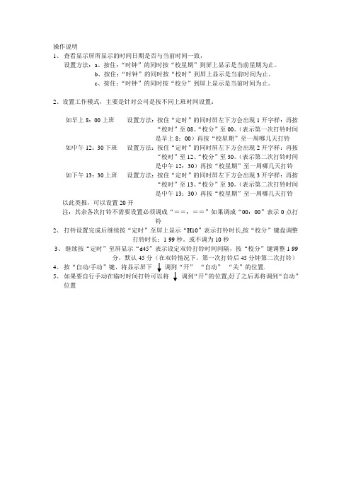
操作说明
1、查看显示屏所显示的时间日期是否与当前时间一致,
设置方法:a、按住:“时钟”的同时按“校星期”到屏上显示是当前星期为止。
b、按住:“时钟”的同时按“校时”到屏上显示是当前时间为止。
c、按住:“时钟”的同时按“校分”到屏上显示是当前时间为止。
2、设置工作模式,主要是针对公司是按不同上班时间设置:
如早上8:00上班设置方法:按住“定时”的同时屏左下方会出现1开字样:再按
“校时”至08、“校分”至00。
(表示第一次打铃时间
是早上8:00)再按“校星期”至一周哪几天打铃如中午12:30下班设置方法:按住“定时”的同时屏左下方会出现2开字样:再按
“校时”至12、“校分”至30。
(表示第二次打铃时间
是中午12:30)再按“校星期”至一周哪几天打铃如下午13:30上班设置方法:按住“定时”的同时屏左下方会出现3开字样:再按
“校时”至13、“校分”至30。
(表示第二次打铃时间
是中午13:30)再按“校星期”至一周哪几天打铃以此类推,可以设置20开
注:其余各次打铃不需要设置必须调成“==:==”如果调成“00:00”表示0点打
铃
2、打铃设置完成后继续按“定时”至屏上显示“H10”表示打铃时长,按“校分”键盘调整
打铃时长:1-99秒。
或不调为10秒
3、继续按“定时”至屏显示“d45”表示设定双铃打铃时间间隔,按“校分”键调整1-99
分,默认45分(在双铃情况下,第一次打铃后45分钟第二次打铃)
4、按“自动/手动”键,将显示屏下调到“开”“自动”“关”的位置.
5、如果要自行手动在临时时间打铃可以将调到“开”的位置,好了之后再将调到“自动”
位置。
好帮手电动起子说明书

生产厂:上海高手机电有限公司地 址:上海市闵行区中春路7166号变频大型系列使用说明书2.5~4.02.6~4.53.0~5.03.0~5.03.5~5.54.0~6.0700-1000700-1000500-700低压全自动电动起子扭力范围无载转速适用螺丝牙径(mm)机械螺丝自攻螺丝rpm 好幫手电气动起子全系列扭力对照表区分机型kgf.cm 使用前请仔细阅读本说明书ASA-9000(PS)20~50ASA-7000(PS)ASA-8000(PS)7.0~3012~40警告:在进行维修前必须将电源线自插座拔离,非专业人员请勿尝试维修本电动起子。
·请确定插座电源电压及电动起子所需电压相符。
·杂乱工作场所易造成伤害,勿将电动起子及配件放于水边,工作场所照明良好。
·确认插座的电压源及接地状况:起子本身附有接地导线,使用时请插在附有接地装置的插座上,不但可保障漏电安全,并可 排泄起子因操作磨擦所产生的静电及噪声干扰。
·切勿在电动起子非设定功能上操作,如钻孔等。
·不可使用电源线拉提电动起子或从插座猛拉开,避免电源线因长时间弯折导致断线,避免 电源线接触到热源、油污、化学剂等物品或磨擦到尖锐的物体边缘。
·插头插入起子或电源供应器插座时,它有方向性,必须对准插座内之导丘点后,方可用力插 入,然后以旋钮固定在起子或电源供应器上。
如此会减少因拉扯而断线的发生。
·为确保自身权益,保固期间内请勿拆修电动起子或控制器,请参考《保用范围条款》。
操作须知·操作前,确认被锁物已被强制固定后操作,避免锁螺丝时带动被锁物旋转而导致人员伤害。
·起子运转中切勿任意变换起子之转向,必须放松押扣板或放松下压力量﹙PS机型﹚, 待马达完全停止后方可切换。
·扭力设定:旋转扭力调整环来设定起子的扭力;顺时针旋转为扭力增大,逆时针旋转为扭力减小。
QBZY 系列全自动表面张力仪操作手册说明书

上海方瑞仪器全自动表面张力仪操作说明书型号:QBZY-1、QBZY-2、QBZY-3目录第一章概述 (3)仪器特色 (3)第二章基本原理 (4)2.1 什么是表面张力? (4)2.2 白金板法 (5)2.3 白金环法 (6)2.4 白金板与白金环比较 (7)第三章表面张力仪的技术参数及组成 (8)3.1技术指标 (8)3.2系统组成 (8)3.3仪器部件示意图及说明 (9)第四章铂金板操作方法 (11)4.1 请在正式作测试前,确认已经熟悉以下注意事项: (11)4.2 故障排除方法: (13)4.3 测试方法: (14)4.3.1标准测试方法:(最常用) (14)附件:浮力修正表: (16)4.3.2中高粘度液体的测量: (16)4.3.3测量表面活性剂 (17)4.3.4测量界面张力的方法 (18)第五章仪器校正 (19)第六章铂金环使用(选配件) (23)附录1:20℃时某些液体的表面张力值 (31)附录2:不同温度时水的密度、粘度及与空气界面上的表面张力 (32)第一章概述众所周知表面张力 (SURFACE TENSION) 是决定液体溶解度(solubility)、润湿性(wetting)、发泡性(bubbling)、涂布(coating)及渗透性(permeability)等性质的基本原理。
人们经常对某种给定的液体进行表面张力分析,进而研究该液体相对于其他液体或固体的物理表现。
而这种研究正是产业化过程中进行质量控制的基本手段。
Q BZY系列全自动表面张力仪恰好为客户进行表面张力方面的研究提供了完善的解决方案。
它完美的“在线性”,完全能够测出因溶液时间变化或表面活性剂存在而出现的变化值。
而且,它的应用范围更会因使用者合理且精明的运用而更为广泛。
仪器特色相对于其他表面张力仪而言,Q BZY系列表面张力仪包括但不仅限于如下优点:²全自动化测量,将人为误差降到最低;²自动读取表面张力平衡值;²一键清零(0-全量程间的任意数值),绝对准确;²一键校正配合随机附带的标准砝码,准确迅速;²采用国际先进的传动技术,将试样平台升降更平稳可靠,且无震音。
DFD-系列电动操作器 说明书

ISO9001 质量认证企业推荐单位天津市企业联合会理事单位RDFD-系列电动操作器 使用说明书天津贝尔自动化仪表技术有限公司TIANJIN BELL AUTOMATIC INSTRUMENT TECHNOLOGY CO.,LTD●操作器在电动执行机构系统中的主要作用有2种:1.在控制室内为操作者提供可视的输入及反馈信号值,便于观察现场阀位。
2.在控制信号失灵或检修系统时,可用其直接操作电动执行机构,完成事故检修情况下的人工手动操作。
操作器型号配电动执行机构型号备 注DFD-05DFD-0500普通系列DKJ-510DKJ-5100以下但推荐使用DFD-09, DFD-0900DFD-07DFD-0700普通系列DKJDKZ带上、下电限位功能DFD-09DFD-0900普通系列DFD-130DFD-1300引进系列可输出4~20mA电流控制信号DFD-1900DFD-1900T引进系列●各种型号适用范围:系列DKJDKZ系列推荐使用角行程直行程多转系列角行程直行程多转系列可输出无源开关量控制信号地址:天津市南开区黄河道519号 邮编:300112 电话:022-27528973/27772369 传真:022-27529983网址:www.bellaut.com 邮箱:fw@bellaut.com天津贝尔自动化仪表技术有限公司TIANJIN BELL AUTOMATIC INSTRUMENT TECHNOLOGY CO.,LTD感谢您订购贝尔公司产品,欢迎您给我们的产品和工作提出宝贵意见。
BELL 天津市贝尔自动化仪表技术有限公司电动操作器目录目 录1.DFD-05,DFD-0500 电动操作器 …………………………………………………………………1 1.1 用途………………………………………………………………………………………………1 1.2 主要技术性能……………………………………………………………………………………1 1.3 工作原理及结构说明……………………………………………………………………………1 1.4 仪表的安装与维修使用…………………………………………………………………………32.DFD-09,DFD-0900, DFD-07,DFD-0700电动操作器…………………………………………5 2.1 用途………………………………………………………………………………………………5 2.2 主要技术性能……………………………………………………………………………………5 2.3 工作原理及结构说明……………………………………………………………………………5 2.4 仪表的安装与维修使用…………………………………………………………………………73.DFD-130,DFD-1300 电动操作器 …………………………………………………………………11 3.1 用途………………………………………………………………………………………………11 3.2 主要技术性能……………………………………………………………………………………11 3.3 工作原理及结构说明……………………………………………………………………………11 3.4 仪表的安装与维修使用…………………………………………………………………………124.DFD-1900,DFD-1900T 电动操作器………………………………………………………………13 4.1 用途………………………………………………………………………………………………13 4.2 主要技术性能……………………………………………………………………………………13 4.3 工作原理…………………………………………………………………………………………135.贮存………………………………………………………………………………………………………166.保证事宜…………………………………………………………………………………………………167.其它产品…………………………………………………………………………………………………161. DFD-05,DFD-0500 电动操作器1.1用途DFD-05型电动操作器是工业过程测量和控制系统终端控制单元的辅助装置,可以完成电动执行机构手动,自动工作状态切换,远方操作和自动跟踪无扰动切换等功能。
CROWN-PT手持式电动工具说明书

Read and understand the manual before using the machine.操作前,请务必认真阅读使用说明书Instruction manualen 说明书中文上海脉链五金工具有限公司上海市江场三路138号4楼Shanghai Merit Link Hardware & Tools Co., Ltd.138 Jiangchang 3rd road, 4th floor, ShanghaiWarning! Read all the warnings and instructions.Failure to observe the following warnings and instructions would lead to electric shock,fire and/or serious damages.Keep all the warnings and instructions for reference.1) Workplacea) Keep workplace clean and bright. Messy and dark place would cause accidents.b) Do not operate the electric tool in explosive environments such as places whereflammable liquid, gas or dust is stored. Sparks produced by electric tool would ignite thedust or the gas.c) Keep children and spectators away and operate the electric tool. Inattention would letyou lose the control of tool.2) Electric safetya) Plug of electric tool must match the socket.Plug cannot be refitted in any way.Changeover plug cannot be used for grounded electric tool. Original plug and matchedsocket would reduce danger of electric shock.b) Prevent human body from touching grounded surfaces, such as pipeline, cooling finand refrigerator. The danger of electric shock would be increased if your body is grounded.c) Do not expose the electric tool in the rain or damp environment. Water entering theelectric tool would increase the danger of electric shock.d) Do not use wires arbitrarily.Do not use wire to move and pull the electric tool or pull outits plug. Keep electric tool away from heat, oil, sharp edge or moving parts. Damaged ortwisted wire would increase the danger of electric shock.e) When you use the electric tool outside, use external wires and cables that are suitablefor outdoor application. Wires suitable for outdoor application would reduce the danger ofelectric shock.f) If it is inevitable for the electric tool to be exposed in damp environment, use residualcurrent device. Application of RCD would reduce the danger of electric shock.3) Personal safetya) Keep alert. Focus on the operation and stay conscious when using the electric tool.When you feel tired or have a drug, alcohol or therapy reaction, do not operate electrictool. Instant negligence in the operation of electric tool would lead to serious personal injury.b) Use personal protective device and wear goggles all the time. Safety protection devicessuch as dust mask, antiskid boots, helmet, hearing protection device used under propercircumstances would reduce personal injury.c) Prevent accidental startup. Make sure the switch is off when you are connecting thetool with power and/or battery holder, picking up or moving the tool. When you hand is onthe switch of connected power or the switch is on, inserting the plug would lead to danger.d) Before the electric tool is connected, take off all the regulating keys or wrenches.Wrench or key left on the rotating part of electric tool would lead to personal injury.e) Do not reach out your hand too far. Pay attention to the standing place and balance of thebody from time to time so that you can better control the electric tool when the accidenthappens.f) Proper dressing. Do not wear loose clothes or wear accessories. Keep clothes, glovesand hair away from moving parts. Loose clothes, accessories or hair may be drawn in themoving parts.g) If devices that shall be connected with chip removing and dust collecting equipmentare provided, make sure they are connected well and properly. Utilization of these devicescan reduce the danger caused by dust and chips.4) Utilization and cautions of electric toola) Do not abuse and overuse electric tool. Use it properly according to its purposes.Choose electric tool with properly designed rated value to make your work more effective andsafer.b) If the switch cannot be connected or the tool power cannot be cut off, do not use theelectric tool. That the electric tool cannot be controlled by switch is dangerous and the toolEnglish118must be repaired.c) Before regulating, replacing any auxiliary or storing the electric tool, pull off the plugfrom the power and/or separate the battery holder and the tool. This protective measurewould reduce the danger caused by accidental startup of tool.d) Place the unused electric tool in the area beyond the reach of children and do not letpeople who are not familiar with the tool or instructions operate electric tool. Theelectric tool is dangerous in the hands of untrained user.e) Maintain electric tool. Check whether moving parts are regulated well or locked andcheck whether parts are damaged and other conditions that may affect the operation ofelectric tool. If a part is damaged, the tool shall be repaired before the use. Manyaccidents are caused by bad maintenance of electric tool.f) Keep cutter sharp and clean. Well maintained cutter with sharp cutting edge is not easy toget stuck and easy to control.g) Use the electric tool, accessories and cutter of the tool according to operationinstructions, operating conditions and proceeding operation. That the electric tool isapplied in the operations that do not conform to its purposes may lead to danger.5) Repaira) Please give your electric tool to the professional repairmen so that they can repair thetool with the same fittings, which would guarantee the safety of repaired electric tool.II.Safe instructions of circular sawWarning: do not use abrasive saw blade!Dangers:1) Keep your hand away from sawing area and saw blade all the time. The other hand shallalways hold the assistant handle or motor case.If both hands hold the circular saw, theywould be cut by the blade.2) Do not touch the bottom of work piece. Shield cannot prevent the danger of saw blade belowthe work piece.3) Adjust sawing depth to the thickness of work piece. The saw tooth below the work piece shallnot be as high as one tooth.4) Do not saw the work piece when you hold it or put it on your thigh. Clamp the work piecetightly on a steady platform.Proper support for the work piece is significant to reducepersonal injury and occurrence of stuck blade or operation failure.5) When the sawing machine may touch concealed wire or wire of itself during the operation,hold the insulated surface of electric tool. The exposed metal part of tool would be electrifiedwith it touches “charged” wire and the operator would get electric shock.6) When the tool serves as a splitting saw, use splitting saw fence and straight-sided guider.It improves sawing precision and reduces the probability of stuck blade.7) Use saw blade with proper size and axis shape (rhombic or circular) all the time. That sawblade and clamping part of circular saw do not match would lead to eccentric rotation and furtherresult in failure.8) Do not use washer and bolt with damages or unconformable sizes. Washer and bolt of bladeare specially designed for the circular saw to improve operation and guarantee safe running.9) Check whether the opening and closing actions of mobile shield are flexible every timebefore using it. If the mobile shield cannot retract rapidly, do not operate circular saw. Donot clamp or tie the mobile shield on the start position.If the circular saw falls suddenly,mobile shield would be curved and deformed. Lift the mobile shield with retraction handle tomake sure the shield can retract in any angle and at any depth and would not touch saw bladeand any other parts.10) Check the service condition of spring of mobile shield. If the shield and spring cannotwork normally, repair it before use.The mobile shield would move slowly because of partdamage, glue sedimentation or chip accumulation.11) Lift the mobile shield manually only in special sawing, such as “insert sawing” and“combined” sawing. Use retraction handle to lift the mobile shield. When the saw bladefirst cuts into the sawing material, you must put down the shield immediately. The mobileshield would retract automatically in all the other sawing operations.12) The mobile shield must cover the saw blade all the time before placing the circular sawon the platform or ground. Unprotected and inertial saw blade would make the circular sawretract and saw the objects on its stroke. The time for the saw blade to stop since it is firstreleases shall be considered.Further safe instructions of different circular sawsEnglish17216Rebound reason and protection for operation:Rebound is the sudden action when the saw blade is squeezed, stuck or deviated from the center. It makes the circular saw out of control, lifted off the work piece and bound to the operator.When the saw blade is squeezed or clamped tightly by the drawn notch, blocked rotation of saw blade and motor reaction would drive the entire machine rebounding rapidly towards the operation. If the saw blade is twisted or deviated from sawing surface, saw teeth on the back edge of blade would cut into the upper surface of wood and the blade would come out of the notch and rebound towards the operator.Rebound is the result of misuse of circular saw and/or incorrect operation procedure or condition. Take the following preventive measures to avoid rebound.a) Both hands hold the handle of the circular saw tightly. Stretch arms to withstand the rebound force. Body is on any side of circular saw and shall not be aligned with saw blade. Rebound would make the circular saw bound backwards. The rebound force can be controlled by the operator if proper preventive measures are taken.b) When the saw blade is stuck or the sawing is stopped for any cause, release switch trigger and hold still the circular saw still in the material until the blade is fully stopped. Do not try to move the circular saw out of work piece or pull it backwards when the blade is rotating or rebound would happen. Investigate and take correct measures to eliminate the cause of stuck blade.c) When the circular saw is restarted in the work piece, align the saw blade with notch and check whether saw teeth are inserted into material. If the blade is stuck, it would come out and rebound from the work piece when the tool is restarted.d) Support large board to reduce the danger of squeeze and rebound of saw blade. Large board droops because of self weight. The supports must be placed on the both sides below the board, close to the cutting line and edge of board.e) Do not use dull or broken saw blade. Un-abraded or improper installed saw blade would form narrow saw cut, resulting in fierce abrasion and the blade being stuck or rebounded.f) Sawing depth and incline angle regulating lock knob must be tightened and fixed before sawing. If the blade regulator moves during the sawing, the blade would be stuck or rebounded.g) Be careful when “insert-sawing” the existing wall or other dead zones. The machine would saw the objects that cause the rebound when pulling out the saw blade.Sign explanationAttention: please see clearly the product model on the tool nameplate. The same machine would have different parameters. The voltage range applicable to the model is 220-230 (V~) 50/60 (Hz). Itis not applicable to low-voltage region and countries with special electricity provisions.Read the instruction manualPlease wear earmuffsWear eye protection.D o u b l e -i n s u l a t i o n s i g n o f I I -category tool English3Waste electrical products should not be disposed of with household waste. Please recycle where facilities exist. Check with your Local Authority or retailer for recycling adviceIII.Introduction of circular sawThe product is a tool powered by single-phase series motor and driving the saw blade to saw via transmission mechanism. It is applied to sawing wood, fiberboard and other similar materials.Get familiar with your toolNote: We recommend you to choose accessory from the store where you purchased the electric tool. Please choose the correct accessory you need for your work.Major technical parameters English41. Switch knob2. Lock bar of shaft3. Auxiliary handle4. Switch trigger5. Depth indicator6. Main handle7. Cable sheath8. Baseplate9. Mobile shield 10. Guiding ruler 11. Rotating direction of saw blade 12. Lock bolt 13. Depth lock knob 14. Internal pressing plate 15. Saw blade16. External blade 17. Screw 18. Opening direction of mobile shield 19. Angle lock knob 20.Fixed guard 21.Spanner Product model CT15188-185CT15188-190CT15210-235Rated voltage (V~)220-230220-230220-230Frequency (Hz)50/6050/6050/60Rated power (W)150015002000No-load speed (r/min)55005500450090° cutting depth (mm)63.5668545° cutting depth (mm)444660Maximum setting angle (°)454545Saw blade diameter (mm)185190235Central hole diameter of saw blade (mm)202025.4Net weight (kg) 4.24.27.1Protection degree Insulation degreeEEE中文15故 障产 生 原 因排 除 方 法接电后电机不运转1.电源断了2.接头松落3.开关接触不良或不动作4.电枢或定子线圈烧坏5.碳刷与换向器表面不接触 1.修复电源或更换电缆线2.检查所有接头3.修理或调换开关4.更换电枢或定子线圈5.更换碳刷 接电后电机不运转接电或工作后有不正常的叫声,且不旋转或转得很慢1.开关触点烧坏2.机械部分卡住或运动部件擦到3.电枢少量短路或开路4.电源电压低5.润滑脂太多1.修理或更换开关2.检查机械部分3.修理或更换电枢4.调整电源电压5.选择适量的润滑脂减速箱过度发热1.减速箱内缺乏润滑脂或润滑脂变脏2.传动部分配合不好或有杂质落人内部1.添加或更换润滑脂2.检查传动部分或清除杂质机壳表面过度发热1.绕组潮湿2.装配不正确使电枢运转不灵活3.电源电压下降1.烘干绕组2.检查电枢是否卡住或擦铁芯3.调整电源电压换向器上产生环火或较大火花1.电枢短路2.电刷与换向器接触不良3.换向器表面不光洁1.修复电枢2.更换碳刷3.清除杂物,使换向器表面光洁保留修改权 此说明书,本公司保留修改权售后服务 上海脉链五金工具有限公司上海市江场三路138号4楼联系电话:************传真:************服务热线:4008832658 (中国地区)网址:在干燥、清洁和没有腐蚀性气体的环境中。
打铃仪 方案一
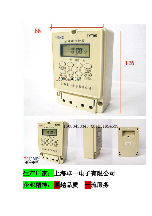
生产厂家:上海卓一电子有限公司企业精神:卓越品质一流服务企业标准:ISO9001 CCC CQC CE认证产品名称:全自动打铃仪型号:ZYT05产品尺寸:126*88*51MM壁挂式/螺栓固定打铃时长:1秒-99秒可调一周内任意设置额定电压:180-240VAC/50HZ编程次数:每天可设置20次内置7号电池一.适用范围本产品系无火花电铃,不锈钢,适用于工矿企业、机关团体、公共场所学校及仪器设备配套的交流50HZ,电压至220V以下的电路中,作呼唤或通知信号用,另外也适用于家庭作门铃,报警等使用。
二,正常工作条件1。
海拔高度不超过2000米2。
周围介质湿度不高于+40度及不低于-25度空气相对温度不大于90%(当温度在+25度)3。
在周围空气中无易燃性及腐蚀性气体或导电性尘埃及无显著摇动和冲击振动的环境中使用。
4。
在额定电压±10%时能正常工作,连续工作不大于10分钟。
5。
污染等级为2级,安装类别为II类。
一、功能和用途本产品能根据用户设定的时间,可以用做工厂、学校、机关自动打铃控制。
如果配相应的语言片,还可以作为家庭、机关里日程安排的语音提示,实现自动、及时准确的警示作用。
二、特点1、可直接控制电铃(打铃器触点容量10A阻性);2、每天走时误差及打铃误差小于0.5秒;3、每天可设20级打铃,最多可实现40次打铃;4、液晶显示、中文界面、安装方便;5、打铃时间可按天或周循环。
6、打铃延迟时间1秒~99秒可调;7、打铃间隔时间1分~99分可调;8、具有“单铃”、“双铃”双重功能;9、具有手动打铃功能。
三、定时打铃设置1、调时钟:按住“时钟”键不入的同时再依次按“校星期”键、“校时”键、“校分”键,分别将以上时间参数按标准进行调整即可。
2、打铃时间参数设置:2.1、打铃时间设置:按动“定时”键,液晶显示屏则显示“1开”(第一组可铃设置提示),可按所需时间参数分别按动“校时”、“校分”键进行设置,如时间参数设置完毕后,再对所需星期参数进行设置。
打铃仪设定

微电脑全自动打铃仪.打铃器功能和用途本产品KG3022T 型以高性能微电脑芯片为核心,可根据用户设定进行自动打铃,一天内最多可实现46次打铃,并为用户提供时钟自动校准功能,具有走时准确、操作方便等特点.广泛应用于学校.企事业单位的自动打铃控制。
性能指标:1.工作电源220V/50Hz;/25a2.适用电压范围160V~240V;3.消耗功率<3W;4.外形尺寸179×139×66mm;5.重量1100g;6.计时误差<±0.5秒/天;7.闹钟时间0~59秒;8.工作模式:每日相同、每日不同、五天工作制、六天工作制;9.有46组闹铃时间,手动、自动两用显示屏说明星期含义如下所示:其它说明1、若临时要求终止执行自动打铃程序,在时钟动行状态,按S键一次,“”静止,使打铃程序冻结,若要恢复执行自动打铃程序,再按S键一次使“”闪烁,表示打铃仪自动打铃程序开始工作;2、若临时需打铃,可在时钟运行状态下按“-”(减数键)手动打铃或按产品背面有“开/关”键;3、在打铃状太下需临时终止打铃,按任意键均可;4、若打铃仪发生意外故障(如死机等),不能正常打铃,可用产品背面的开关手动打铃,再按照“故障排除”中介绍的方法排除故障;5、长期不使用本产品,请将产品后面的锁调到“关”状态,以节约电源。
操作说明(一)按键说明:本产品的操作提供五个按键,分别是:M功能键:按此键转换显示屏显示内容,实现时钟运行状态、时钟设置状态、参数设置状态、定时设置状态的转换;S选择键:按此键选择某种功能中需要调整设置的各个参数;+加数键:对选中的项目向上加数(即实现递增变化);-减数键:对选中的项目向下减数(即实现递减变化),在时钟运行状态可实现手动打铃;复位键:清除所有设置,回到系统初始状态,即显示屏处于时钟运行状态,当前时间为10:00、星期日、打铃时长为10S、工作模式为每日相同、无打铃设置。
请注意:如果您在操作过程发生错误不知如何纠正或因其它原因不能顺利完成,请按M功能键回到时钟运行状态或按复位键回到初始状态重新开始。
TD-100和MT-100手推器操作与维护手册说明书

Operation and Maintenance Manual for the TD-100and MT-100 HandpiecesP/N 5050-0532TITLE PAGE Safety Guidelines (3)Handpiece Connection (3)Tip Cartridge Installation (3)Accessory and Replacement Parts (4)Tips (5)Corrective Maintenance (10)Service (10)PACE WORLDWIDE LIMITED WARRANTY STATEMENT (11)Contact Information (12)Safety GuidelinesThe following are safety precautions that personnel must understand and follow when using or servicing this product.1.POTENTIAL SHOCK HAZARD - Repair procedures on PACE products should be performedby Qualified Service Personnel only. Line voltage parts may be exposed when theequipment is disassembled. Service personnel must avoid contact with these parts whentroubleshooting the product.2. To prevent personnel injury, adhere to safety guidelines in accordance with OSHA and otherapplicable safety standards.3. Heater Cartridge Tips are hot when the handpiece is powered on and for a period of timeafter power off. DO NOT touch the cartridge. Severe burns may result.4. PACE Tip & Tool Stands and handpiece cubbies are designed specifically for use with theassociated handpiece and houses it in a manner that protects the user from accidental burns.Always store the handpiece in its holder. Be sure to place the handpiece in its holder afteruse and allow for cooling before storing.5. Always use PACE systems in a well ventilated area. A fume extraction system such as thoseavailable from PACE are highly recommended to help protect personnel from solder fluxfumes.6. Exercise proper precautions when using chemicals (e.g., solder paste). Refer to the MaterialSafety Data Sheet (MSDS) supplied with each chemical and adhere to all safety precautions recommended by the manufacturer.Handpiece ConnectionConnect the handpiece connector plug into the Power Receptacle in the followingmanner.1. Align guide on the connector with slot on power receptacle.2. Insert connector into power receptacle.3. Turn the connector housing clockwise to lock in place.Tip Cartridge InstallationBoth TD-100 and MT-100 tip cartridges are fitted with a key lock device. This feature ensures that tip cartridges are held firmly in position and will maintain their orientation. MT-100 tip cartridges CANNOT be fully inserted into the TD-100 and TD-100 tip cartridges CANNOT be fully inserted into the MT-100. To install a tip cartridge, please follow the procedure below.1.of the handpiece.2. Push the tip cartridge all the way into the handpiece.To remove a tip cartridge, use the included hot grip removal pad to grasp the tip cartridge and pull the tip cartridge out of the handpiece. Be careful when completing this procedure as the tip cartridge may be hot and direct contact can cause injury.Tipscartridges can be changed at any time and without turning off the power to the unit.Accessory and Replacement PartsDescription PACE Part NumberTip Case – Holds 10 Tips (Tips not included)1310-0034-P1Tip Stand – Allows for an additional 10 tips to be stored on the tool stand. (Shown with TD-100 Tool Stand, tips not included)1321-0639-P1TD-100 Handpiece (Tip cartridge not included)6010-0132-P1Replacement TD-100 cord assembly3008-0131-P1Replacement O-rings for TD-100. Package of 5.1213-0090-P5TD-100 Tool Stand (TD-100 Handpiece and tips not included)1257-0258-P1MT-100 Handpiece (Tipsnot included)6010-0140-P1MT-100 Tool Stand 6019-0069-P1Hot Grip Removal Pad1100-0307-P1Available TipsA wide variety of tip cartridges are available for use with the TD-100 and the MT-100 Handpieces. Please refer to the table below for available tip cartridge styles.PACE P/N Description1124-0001-P11/32" Conical Sharp Extended1124-0002-P11/64" Conical Sharp1124-0003-P1 1/64" Conical Sharp Bent 30 Degrees1124-0004-P11/64" Conical Sharp Extended1124-0005-P1 1/32" Conical1124-0006-P1 3/128" Conical1124-0007-P11/16" 90 Degree Chisel1124-0008-P1 3/64" 30 Degree Chisel1124-0009-P13/64" 30 Degree Bevel1124-0010-P1 13/64" Chisel1124-0011-P1 1/64" 60 Degree Bevel1124-0012-P1 1/32" 30 Degree Chisel1124-0013-P13/32" 30 Degree Chisel1124-0014-P1 5/64" 60 Degree Bevel1124-0015-P11/64" Conical, Sharp, Bent 30 Degrees,Extended1124-0016-P1 3/64" Chisel Bent 30 Degrees1124-0017-P1 1/16" 60 Degree Chisel1124-0018-P1 1/32" Conical Sharp Extended1124-0019-P1 1/16" 30 Degree Chisel1124-0020-P1 1/8" 90 Degree Chisel1124-0021-P1 3/128" Conical Sharp Bent 30 Degrees1124-0022-P1 1/16" Conical Sharp1124-0023-P1 1/8" 90 Degree Chisel Extended1124-0024-P1 1/16" 30 Degree Bevel1124-0025-P1 1/16" Conical Sharp Extended1124-0026-P1 1/16" Chisel Bent 30 Degrees1124-0027-P1 3/128" Conical Sharp, Extended1124-0028-P1 3/64" Chisel, Bent 30 Degrees, Extended1124-0029-P1 1/32" 30 Degree Bevel1124-0030-P1 1/32" Conical Sharp1124-0031-P1 Heat Staking1124-0032-P1 MiniWave1124-0033-P1 Angled MiniWave, 3.3 mmChiselSided1124-0034-P1 Single1124-0035-P1 Angled MiniWave, 2.4mmConical1124-0036-P1 1/128"1124-0037-P1 1/4 Flat Blade1124-0038-P1 Single Sided Chisel, Fine Pitch1124-0039-P1 Angled MiniWave, Fine Pitch1124-0040-P1MicroFine Single Sided Chisel, 0.9mm(.035”)1124-0041-P1MicroFine Single Sided Chisel, 1.1mm(.045”)1124-0042-P1MicroFine Conical, 0.25mm (.01”)1124-0043-P1MicroFine Bent Conical, 0.75mm (.03”)1124-0044-P1MicroFine Bent Conical, 0.5mm (.02”)1124-0045-P1Angled Micro-Wave Tip1124-0046-P1 Micro-WaveTipSurface Mount Removal Tips for TD-100 Soldering IronComponentTypeDimension A Dimension B PartNumberChip 402Angle 2.2mm (.085”) 1124-0518-P1Chip 1808 5mm (.195”) 1124-0520-P1Chip 402 1mm (.04”) 1124-0521-P1SOT 23 1.8mm (.07”) 1124-0522-P1SOT 89 2.8mm (.11”) 1124-0523-P1Chip 1206 3.6mm (.142”) 1124-0524-P1Chip 0805 2.4mm (.095”) 1124-0525-P1SOIC 14/16 5.2mm (.205”) 10.5mm (.415”) 1124-0504-P1SOIC 20 9.6mm (.377) 13.6mm (.535”) 1124-0505-P1SOP 28 10.8mm (.426”) 18.6mm (.734”) 1124-0506-P1SOP 40 11.9mm (.467”) 25.7mm (1.01”) 1124-0507-P1SOP 44 13.1mm (.516”) 28.4mm (1.12”) 1124-0508-P1TSOP 56 18.8mm (.739”) 14.1mm (.557”) 1124-0509-P1TSOP 28 12mm (.471”) 8.5mm (.333”) 1124-0510-P1SOIC 8 5.1mm (.202) 4.65mm (.183”) 1124-0519-P1TSOP 40 18.8mm (.74”) 10.4mm (.410) 1124-0526-P1PLCC 28Socket 9.3mm (.365”) 9.3mm (.365”) 1124-0511-P1PLCC 32 14.2mm (.561”) 11.7mm (.459”) 1124-0512-P1PLCC 44 16.8mm (.662”) 16.8mm (.662”) 1124-0513-P1QFP 144 20.6mm (.81”) 20.6mm (.810”) 1124-0514-P1PLCC 28 11.8mm (.465”) 11.8mm (.465”) 1124-0515-P1QFP 100/128 22mm (.865”) 16mm (.628”) 1124-0516-P1PLCC 20 9.3mm (.365”) 9.3mm (.365”) 1124-0527-P1PLCC 18 7.6mm (.3”) 12.8mm (.505”) 1124-0528-P1TQFP 80 12.5mm (.491”) 12.5mm (.491”) 1124-0529-P1PLCC 52 19.4mm (.762”) 19.4mm (.762”) 1124-0530-P1QFP 80/100 26.6mm (1.05”) 26.6mm (1.05”) 1124-0531-P1Blade 10.8mm (.425”) 1124-0501-P1Blade 16mm (.630”) 1124-0502-P1Blade 21.2mm (.835”) 1124-0503-P1Blade 25MM (.984”) 1124-0532-P1 Surface Mount Removal Tips for MT-100 MiniTweezCorrective MaintenanceThe TD 100 handpiece features a replaceable O-ring that protects the contact area from flux fume and other contamination. The O-ring may need to be replaced over time. To replace the O-ring follow the procedure below:1. Disconnect the TD 100 from the power source2. Remove the tip cartridge3. Unscrew the cap from the back of the TD 1004. Slide the connector assembly out of the handle5. Remove and replace the old O-ring from the connectorassembly (Old “O-ring” may remain in handle)6. Reinstall the connector assembly. Be sure to line up thekeyways on the handle and connector assembly. Do notforce the connector assembly into the handle.7. Reinstall the cap and make sure it is fully seated againstthe handle8. Install a tip cartridgeThe O-rings on the MT-100 do not need to be replaced.Handpiece TroubleshootingMost malfunctions are simple and easy to correct. Refer to Table 3.Symptom ProbableCauseSolutionDefective HeaterChange Tip Cartridge Handpiece willnot heatPower SourceMalfunctionContact PACETable 3: Troubleshooting ServicePlease contact PACE or your local distributor for service and repair.©2003 PACE Inc., Annapolis Junction, MarylandPage 12 of 12 All Rights Reserved PACE Incorporated retains the right to make changes to specifications contained herein at any time, without notice. Contact your local authorized PACE Distributor or PACE Incorporated to obtain the latest specifications.The following are trademarks and/or service marks of PACE, Incorporated, MD, USA:INSTACAL ™, FUMEFLO ™, HEATWISE ™, PACEWORLDWIDE ™, PERMAGROUND ™,POWERPORT ™, POWERMODULE ™, TEMPWISE ™, TIP-BRITE ™, AUTO-OFF ™, andTEKLINK ™.The following are registered trademarks and/or service marks of PACE Incorporated, Annapolis Junction Maryland U.S.A.ARM-EVAC ®, FLO-D-SODR ®, MINIWAVE ®, PACE ®, SENSATEMP ®, SNAP-VAC ®,SODRTEK ®, SODR-X-TRACTOR ®, THERMOFLO ®, THERMOJET ®, THERMOTWEEZ ®,VISIFILTER ®, THERMO-DRIVE ®, and TOOLNET ®.PACE products meet or exceed all applicable military and civilian EOS/ESD, temperature stability and other specifications including MIL STD 2000, ANSI/JSTD 001, IPC7711, and IPC A-610.Additional copies of this manual or other PACE literature may be obtained from:PACE USA PACE Europe9030 Junction Drive Sherbourne HouseAnnapolis Junction, MD 20701 Sherbourne DriveUSA Tilbrook, Milton KeynesMK7 8HXUnited KingdomTel: (301) 490-9860 (44) 01908-277666Fax: (301) 498-3252 (44) 01908-277777。
上海卓一全自动打铃仪ZYT05

操作说明(一)定时设置◆1.1 首先,查看显示屏所显示的时间是否与当前时间一致。
如需重新校准,按住“时钟”的同时,分别按“校星期”、“校时”、“校分”键,将时钟调到当前时间;◆1.2 按一下“定时”键,显示屏左下方出现“1开”字样 ( 表示第一次打铃时间),再按“校时”、“校分”键,输入打铃时间,然后按“校星期”选择工作模式(即此次打铃在哪几天工作);工作模式提供以下各种模式供您根据实际情况选择:①每日相同(一二三四五六日)②每日不同(一或二或三或四或五或六或日)③半周制(一三五)④半周制(二四六)⑤半周制(一二三)⑥半周制(四五六)⑦五天工作制(一二三四五)⑧六天工作制(一二三四五六)⑨星期六日◆1.3 如果此次打铃时间需执行双铃程序(即在指定时间间隔之后自动进行第二次打铃),则调好时间后再按一下“双铃”(自动/手动)键,显示屏右上方出现双铃符号即可;◆1.4 继续按动“定时”键,显示屏左下方将依次显示“2开、3 开、……、19 开、20 开”字样,参考步骤2、3设置以后各次打铃时间。
◆1.5 若进行若干次打铃设置后已不需要再进行打铃,则必须将其余各次打铃设定调为“==:==”(而非“00:00”),这样才表示此次打铃无程序设定。
(二)打铃参数设置◆2.1 设置完各次打铃时间后,继续按动“定时”键直至显示屏显示“H10”,表示设定打铃时长,再按“校分”键调整,打铃时长的调整范围为1~99秒,若不调,则默认为打铃时长10秒。
◆2.2 继续按动“定时”键,直至显示屏显示“d45”,表示设定双铃打铃时间间隔,其调整范围为1~99分,按“校分”进行调整,若不调,则默认双铃打铃时间间隔为45分(即双铃情况下,第一次打铃后45分钟进行第二次打铃)。
(三) 按“自动/手动”键,将显示屏下方的“”符号调到“自动”位置,此时,打铃器才能根据所设定的时间自动打铃。
(四) 设置完毕后,应按“时钟”键,使显示屏显示当前时间;如设置完后不按任何键,30秒后显示屏自动恢复显示时间。
AT511A使用说明书

AT511A 使用说明书AT511A使用说明书与我们取得联系:上海奔普仪器科技有限公司地址:上海市沁春路1366弄38号803邮编:201199电话:************安全当你发现有以下不正常情形发生,请立即终止操作并断开电源线。
立刻与安柏科技销售部联系维修。
否则将会引起火灾或对操作者有潜在的触电危险。
●仪器操作异常。
●操作中仪器产生反常噪音、异味、烟或闪光。
●操作过程中,仪器产生高温或电击。
●电源线、电源开关或电源插座损坏。
●杂质或液体流入仪器。
AT511A使用说明书为避免可能的电击和人身安全,请遵循以下指南进行操作。
免责声明用户在开始使用仪器前请仔细阅读以下安全信息,对于用户由于未遵守下列条款而造成的人身安全和财产损失,安柏科技将不承担任何责任。
为防止电击危险,请连接好电源地线不可在易燃易爆气体、蒸汽或多灰尘的环境使用仪器。
在此类环境使用任何电子设备,都是对人身安全的冒险。
非专业维护人员不可打开仪器外壳,以试图维修仪器。
仪器在关机后一段时间内仍存在未释放干净的电荷,这可能对人身造成电击危险。
如果仪器已经损害,其危险将不可预知。
请断开电源线,不可再使用,也不要试图自行维修。
如果仪器工作不正常,其危险不可预知,请断开电源线,不可再使用,也不要试图自行维修。
超出范围,仪器所提供的保护措施将失效。
声明:!, $, #,和文字是常州安柏精密仪器有限公司已经或正在申请的商标。
AT511A 直流电阻测试仪Operation Manual简体中文版Simplified ChineseJan, 2006 第一版Rev1.0.0@%©2005 Applent T echnologies, Inc.上海奔普仪器科技有限公司地址: 上海市沁春路1366弄38号803 邮编: 201199网址:AT511A使用说明书常州安柏精密仪器有限公司(以下简称Applent)保证您购买的每一台AT511A在质量和计量上都是完全合格的。
无功耗电子式起动器中文说明书

无功耗电子式起动器使用说明书发明专利:200410065370.X200510038234.6 常熟市天银机电有限公司TY-QZ-002 TY-QZ-203 TY-QZ-003 TY-QZ-204 TY-QZ-005 TY-QZ-205无功耗电子式起动器的特点TY-QZ 系列无功耗电子式起动器是采用高科技电路来达到压缩机启动完成后启动电路与副线圈完全断开的目的。
同PTC 启动器相比可节约电能2.5~3.5W ,提高压缩机的COP 值,达到冰箱节电的效果。
电路设计对压缩机在启动时可能产生的主副绕组相位及阻抗不匹配状态具有调节功能,所以对冰箱压缩机在特定工作情况下有良好的启动性能;还具有同冰箱电路良好的匹配特性(如果冰箱化霜系统借用压缩机线圈做回路同样可以适用)。
本产品所需元件少,可靠性高,采用元器件及元材料均符合国际所规定的各项技术指标。
本产品已申请发明专利。
一、工作原理及启动特性保护器运转电容控制器正温度系数热敏电阻器副线圈主线圈主线圈带运行电容副线圈不带运行电容副线圈二、性能指标:1、 启动后副线圈与启动电路完全断开(无电流);2、 启动时间0.2s ~1.3s 自动调节;3、 恢复时间大于45s ;4、 工作环境:温度-5℃--+90℃,相对湿度20%-90%;5、 额定电压:~220V ;6、 最高使用电压~260V ;7、 最高耐电流8A (副线圈电流,不包括主线圈电流)。
三、测试方法:见图:1、先断开开关K1,将调压器调至所需电压值。
2、闭合开关K2(不闭合会损坏毫安表“mA ”)。
3、闭合开关K1,压缩机会迅速启动——安培表“A ”指针会摆动后迅速回落(安培表摆动如有波动或停顿属正常动作)。
4、等安培表(A )指针回落后,断开开关K2,这时毫安表(mA )应该无电流指示。
该产品合格。
5、断开开关K1,调节调压器到压缩机所需的启动电压(低压起动或高压起动)等待20~30s 后可再做起动试验。
- 1、下载文档前请自行甄别文档内容的完整性,平台不提供额外的编辑、内容补充、找答案等附加服务。
- 2、"仅部分预览"的文档,不可在线预览部分如存在完整性等问题,可反馈申请退款(可完整预览的文档不适用该条件!)。
- 3、如文档侵犯您的权益,请联系客服反馈,我们会尽快为您处理(人工客服工作时间:9:00-18:30)。
操作说明
(一)定时设置
◆1.1 首先,查看显示屏所显示的时间是否与当前时间一致。
如需重新校准,按住“时钟”的同时,分别按“校星期”、“校时”、“校分”键,将时钟调到当前时间;
◆1.2 按一下“定时”键,显示屏左下方出现“1开”字样 ( 表示第一次打铃时间),再按“校时”、“校分”键,输入打铃时间,然后按“校星期”选择工作模式(即此次打铃在哪几天工作);
工作模式提供以下各种模式供您根据实际情况选择:
①每日相同(一二三四五六日)
②每日不同(一或二或三或四或五或六或日)
③半周制(一三五)
④半周制(二四六)
⑤半周制(一二三)
⑥半周制(四五六)
⑦五天工作制(一二三四五)
⑧六天工作制(一二三四五六)
⑨星期六日
◆1.3 如果此次打铃时间需执行双铃程序(即在指定时间间隔之后自动进行第二次打铃),则调好时间后再按一下“双铃”(自动/手动)键,显示屏右上方出现双铃符号即可;
◆1.4 继续按动“定时”键,显示屏左下方将依次显示
“2开、3 开、……、19 开、20 开”字样,参考步骤2、3设置以后各次打铃时间。
◆1.5 若进行若干次打铃设置后已不需要再进行打铃,则必须将其余各次打铃设定调为“==:==”(而非“00:00”),这样才表示此次打铃无程序设定。
(二)打铃参数设置
◆2.1 设置完各次打铃时间后,继续按动“定时”键直至显示屏显示“H10”,表示设定打铃时长,再按“校分”键调整,打铃时长的调整范围为1~99秒,若不调,则默认为打铃时长10秒。
◆2.2 继续按动“定时”键,直至显示屏显示“d45”,表示设定双铃打铃时间间隔,其调整范围为1~99分,按“校分”进行调整,若不调,则默认双铃打铃时间间隔为45分(即双铃情况下,第一次打铃后45分钟进行第二次打铃)。
(三) 按“自动/手动”键,将显示屏下方的“”符号调到“自动”位置,此时,打铃器才能根据所设定的时间自动打铃。
(四) 设置完毕后,应按“时钟”键,使显示屏显示当前时间;如设置完后不按任何键,30秒后显示屏自动恢复显示时间。
(五) 如在使用过程中需要临时打铃或中止打铃,则只需按“自动/手动”键将“”符号调到相应的“开”或“关”的位置。
(六)注意事项
◆6.1 如果本打铃器某一天该打铃的时间没打铃,那可能是因为作定时设置的“星期”没调对,请按照“定时设置”中介绍的方法检查或重调。
◆6.2 如果打铃器在不该打铃的时间打铃,那可能是因为多余的几组打铃时间没有消除,请参照“定时设置”中介绍的方法消除(注意:打铃设置显示“--:--才表示消除,不要以为“00:00”表示消除)。
◆6.3 如果以上两条全部正确,而本开关仍然动作不正常,有可能是“自动/手动”键被人为动作,检查“开、自动、关”的标志“”,将其调回到自动位置。
◆6.4接线时请勿必拧紧接线柱,接接通电源后请勿接触端子部分。
◆6.5本开关工作在无潮湿、腐蚀及高金属含量气体环境中, 请勿使沾染油或水。
◆ 6.6请勿自行修理、分解或改造。
修理、检查等。