MPXV7007GP中文资料
PanelView Plus 7 Performance终端产品目录说明书

Technical DataPanelView Plus 7 Performance TerminalsCatalog Numbers 2711P-T7C22D9P , 2711P-T7C22D9P-B, 2711P-T7C22A9P , 2711P-T7C22A9P-B, 2711P-B7C22D9P , 2711P-B7C22D9P-B, 2711P-B7C22A9P, 2711P-B7C22A9P-B, 2711P-T9W22D9P , 2711P-T9W22D9-B, 2711P-T9W22A9P , 2711P-T9W22A9P-B, 2711P-T10C22D9P , 2711P-T10C22D9P-B, 2711P-T10C22A9P, 2711P-T10C22A9P-B, 2711P-B10C22D9P , 2711P-B10C22D9P-B, 2711P-B10C22A9P , 2711P-B10C22A9-B, 2711P-T12W22D9P , 2711P-T12W22D9P-B, 2711P-T12W22A9P , 2711P-T12W22A9P-B, 2711P-T15C22D9P , 2711P-T15C22D9P-B, 2711P-T15C22A9P , 2711P-T15C22A9P-B, 2711P-B15C22D9P , 2711P-B15C22D9P-B, 2711P-B15C22A9P , 2711P-B15C22A9P-B, 2711P-T19C22D9P , 2711P-T19C22D9P-B, 2711P-T19C22A9P , 2711P-T19C22A9P-BSummary of ChangesThe PanelView™ Plus 7 Performance terminals are operator interface devices. They monitor and control devices that are attached to ControlLogix® and CompactLogix™ 5370controllers on an EtherNet/IP network. Animated graphic and text displays provide operators a view into the operating state of a machine or process. Operators interact with the control system by using touch screen or keypad input.TopicPage Environmental Specifications 2Certifications 3Technical Specifications 4Product Dimensions 7Accessories 8HMI Software 9Additional Resources10TopicPage Updated system memory to 512 MB RAM and 512 MB storage.Updated user memory to 80 MB, approx, nonvolatile storage for applications.4, 5, 62Rockwell Automation Publication 2711P-TD009C-EN-P - July 2016PanelView Plus 7 Performance TerminalsFeatures include the following:•FactoryTalk® View Machine Edition software, version 8.1, provides a familiar environment for creating HMI applications•Windows CE operating system with desktop access for configuration and third-party applications •Connection to ControlLogix or CompactLogix 5370 controllers•Ethernet communication that can support Device Level Ring (DLR), linear, or star network topologies•W eb browser, Microsoft file viewers, text editor, PDF viewer, remote desktop connection, and media player on the terminal desktopEnvironmental SpecificationsThis table lists environmental specifications for the PanelView Plus 7 Performance terminals.AttributeValueTemperature, operating (1)(1)The 19-inch terminals (2711P-T19C22D9P , 2711P-T19C22D9P-B, 2711P-T19C22A9P , and 2711P-T19C22A9P-B) are rated up to 50 °C (122 °F) operating temperature.0…55 °C (32…131 °F)Temperature, nonoperating-25…+70 °C (-13…+158 °F)Heat dissipation (2)(2)Typical BTU measurements were taken at 25 °C (77 °F).7-in. DC (touch, and touch with keypad), 51 BTU (typical)7-in. AC (touch, and touch with keypad), 53 BTU (typical)9-in. DC, 55 BTU (typical)9-in. AC, 58 BTU (typical)10-in. DC (touch, and touch with keypad), 51 BTU (typical)10-in. AC (touch, and touch with keypad), 56 BTU (typical)12-in. DC, 60 BTU (typical)12-in. AC, 67 BTU (typical)15-in. DC (touch, and touch with keypad), 61 BTU (typical)15-in. AC (touch, and touch with keypad), 68 BTU (typical)19-in. DC, 114 BTU (typical)19-in. AC, 119 BTU (typical)Altitude, operating 2000MRelative humidity 5…95% without condensation Vibration 0.012 pk-pk, 10…57 Hz 2 g peak at 57…500 Hz (3)(3)The 15-inch and 19-inch terminals (2711P-T15C22D9P , 2711P-T15C22D9P-B, 2711P-T15C22A9P , 2711P-T15C22A9P-B, 2711P-B15C22D9P , 2711P-B15C22D9P-B,2711P-B15C22A9P , 2711P-B15C22A9P-B, 2711P-T19C22D9P , 2711P-T19C22D9P-B, 2711P-T19C22A9P , 2711P-T19C22A9P-B) are rated to: 0.006 in. pk-pk, 10...57 Hz, 1 g peak at 57...640 Hz.Shock, operating 15 g at 11 ms Shock, nonoperating 30 g at 11 msEnclosure ratingsNEMA and UL Type 12, 13, 4X, also rated IP66 as Classified by ULRockwell Automation Publication 2711P-TD009C-EN-P - July 20163PanelView Plus 7 Performance TerminalsCertificationsThis table lists certifications for the PanelView Plus 7 Performance terminals.Certification (1)(1)When marked. See the Product Certification link at /global/certification/overview.page for Declarations of Conformity, Certificates, and othercertification details.ValuecULuscULus Listed Industrial Control Equipment for use in Hazardous Locations (E10314) per standards ANSI / ISA 12.12.01 and CSA C22.2 No. 213. rated:•Class I, Div 2, Groups A, B, C, DEnclosure type ratings per UL50 and CSA C22.2 No. 94.2-07. Enclosure ingress protection classified by UL per IEC 60529.CE (EMC)European Union 2004/108/EC EMC Directive, compliant with:•EN 61000-6-2; Industrial Immunity •EN 61000-6-4; Industrial Emissions •EN 61131-2; Programmable ControllersCE (LVD)European Union 2006/95/EC Low Voltage Directive, compliant with:•EN 61131-2; Programmable Controllers RCM Australian Radiocommunications Act, compliant with:•AS/NZS CISPR 11; Industrial Emissions RoHS China RoHS, Turkey RoHS, European RoHS KCC Certificate of complianceEtherNet/IPODVA conformance tested to EtherNet/IP specifications4Rockwell Automation Publication 2711P-TD009C-EN-P - July 2016PanelView Plus 7 Performance TerminalsTechnical SpecificationsThe tables in this section provide technical specifications for the PanelView Plus 7 Performance terminals.PanelView Plus 7 Performance 7-in and 9-in TerminalsAttribute 7-in. Touch2711P--T7C22D9P , 2711P--T7C22D9P-B (1)2711P-T7C22A9P , 2711P-T7C22A9P-B (1)Catalog numbers with a -B extension denote terminals that exclude the Allen-Bradley brand marking. Customers can put their own brand labels on these terminals.7-in. Touch with Keypad2711P-B7C22D9P , 2711P-B7C22D9P-B (1)2711P-B7C22A9P , 2711P-B7C22A9P-B 9-in. Touch2711P-T9W22D9P, 2711P-T9W22D9P-B (1)2711P-T9W22A9P , 2711P-T9W22A9P-BOperator input Touch Touch with keypadTouchDisplay type TFT Color Display size, diagonal 6.5-in.9-in. widescreen Viewing area (W x H)132 x 99 mm (5.2 x 3.9 in.)196 x 118 mm (7.7 x 4.6 in.)Display resolution 640 x 480 VGA, 18-bit color graphics 800 x 480 WVGA, 18-bit color graphics Aspect ratio 4:3 5:3Brightness, typical 300 cd/m 2 (Nits)Backlight lifeWhite light-emitting diode, solid-stateLife: 50,000 h min at 40 °C (104 °F) to half-brightness, backlight is not replaceable Touch screenAnalog resistiveActuation rating: 1 million presses Operating force: 100 grams Battery (real-time clock backup)Accuracy: +/-2 minutes per month.Battery life: 4 years min at 25 °C (77 °F)Replacement: CR2032 lithium coin cellMemory:•System •User •512 MB RAM and 512 MB storage•80 MB, approx, nonvolatile storage for applicationsSecure Digital (SD) card slot One SD card slot for external storage; supports cat. no. 1784-SD x cardsUSB ports:•Host •Device •Two USB high-speed 2.0 host ports (type A) support removable flash drives for external storage •One high-speed 2.0 device port (type B) that will be functional in a future releaseOperating system Windows CE with Extended Features and MS Office Viewers (includes FTP , VNC client server, ActiveX controls, PDF reader, third-party device support)Ethernet ports Two 10/100Base-T, Auto MDI/MDI-X Ethernet ports that support Device Level Ring (DLR), linear, or star network topologies Software FactoryTalk View Studio for Machine Edition, FactoryTalk ViewPoint, version 2.6 or laterElectrical Input voltage 24V DC nom (18…30V DC)100…240V AC 24V DC nom (18…30V DC)100…240V AC 24V DC nom (18…30V DC)100…240V AC Power consumption 50 W max(2.1 A at 24V DC)105VA 50 W max(2.1 A at 24V DC)105VA 50 W max(2.1 A at 24V DC)105VA Power supply Supports (SELV) and (PELV) 24V DC supplies (2)(2)DC-powered terminals support safety extra low voltage (SELV) and protective extra low voltage (PELV) 24V DC power supplies such as cat. nos. 1606-XLP95E, 1606-XLP100E, 2711P-RSACDIN.—Supports (SELV) and (PELV) 24V DC supplies (2)—Supports (SELV) and (PELV) 24V DC supplies (2)—Mechanical Weight, approx 1.2 kg (2.65 lb) 1.47 kg (3.25 lb) 1.58 kg (3.48 lb)Dimensions, approx (H x W x D)170 x 212 x 69.6 mm 6.69 x 8.35 x 2.74 in.179 x 285 x 69.6 mm 7.05 x 11.22 x 2.74 in.190 x 280 x 69.6 mm 7.48 x 11.02 x 2.74 in.Cutout dimensions, approx (H x W)142 x 184 mm 5.59 x 7.24 in.142 x 237 mm 5.59 x 9.33 in.162 x 252 mm 6.38 x 9.92 in.Rockwell Automation Publication 2711P-TD009C-EN-P - July 20165PanelView Plus 7 Performance TerminalsPanelView Plus 7 Performance 10-in and 12-in TerminalsAttribute 10-in. Touch2711P-T10C22D9P, 2711P-T10C22D9P-B (1)2711P-T10C22A9P , 2711P-T10C22A9P-B (1)Catalog numbers with a -B extension denote terminals that exclude the Allen-Bradley brand marking. Customers can put their own brand labels on these terminals.10-in. Touch with Keypad2711P-B10C22D9P , 2711P-B10C22D9P-B (1)2711P-B10C22A9P , 2711P-B10C22A9P-B 12-in. Touch2711P-T12W22D9P , 2711P-T12W22D9P-B (1)2711P-T12W22A9P , 2711P-T12W22A9P-B Operator input Touch Touch with keypadTouchDisplay type TFT Color Display size, diagonal 10.4-in.12.1-in.Viewing area (W x H)211 x 158 mm (8.3 x 6.2 in.)261 x 163 mm (10.3 x 6.4 in.)Display resolution 800 x 600 SVGA, 18-bit color graphics 1280 x 800 WXGA, 18-bit color graphics Aspect ratio 4:316:10Brightness, typical 300 cd/m 2 (Nits)Backlight lifeWhite light-emitting diode, solid-stateLife: 50,000 h min at 40 °C (104 °F) to half-brightness, backlight is not replaceable Touch screenAnalog resistiveActuation rating: 1 million presses Operating force: 100 grams Battery (real-time clock backup)Accuracy: +/-2 minutes per month.Battery life: 4 years min at 25 °C (77 °F)Replacement: CR2032 lithium coin cellMemory:•System •User •512 MB RAM and 512 MB storage•80 MB, approx, nonvolatile storage for applicationsSecure Digital (SD) card slot One SD card slot for external storage; supports cat. no. 1784-SD x cardsUSB ports:•Host •Device •Two USB high-speed 2.0 host ports (type A) support removable flash drives for external storage •One high-speed 2.0 device port (type B) that will be functional in a future releaseOperating system Windows CE with Extended Features and MS Office Viewers (includes FTP , VNC client server, ActiveX controls, PDF reader, third-party device support)Ethernet ports Two 10/100Base-T, Auto MDI/MDI-X Ethernet ports that support Device Level Ring (DLR), linear, or star network topologies Software FactoryTalk View Studio for Machine Edition, FactoryTalk ViewPoint, version 2.6 or laterElectrical Input voltage 24V DC nom (18…30V DC)100…240V AC 24V DC nom (18…30V DC)100…240V AC 24V DC nom (18…30V DC)100…240V AC Power consumption 50 W max(2.1 A at 24V DC)105VA 50 W max(2.1 A at 24V DC)105VA 50 W max(2.1 A at 24V DC)105VA Power supply Supports (SELV) and (PELV) 24V DC supplies (2)(2)DC-powered terminals support safety extra low voltage (SELV) and protective extra low voltage (PELV) 24V DC power supplies such as cat. nos. 1606-XLP95E, 1606-XLP100E, 2711P-RSACDIN.—Supports (SELV) and (PELV) 24V DC supplies (2)—Supports (SELV) and (PELV) 24V DC supplies (2)—Mechanical Weight, approx 2.28 kg (5.03 lb) 2.58 kg (5.69 lb) 2.54 kg (5.60 lb)Dimensions, approx (H x W x D)252 x 297 x 69.6 mm 9.92 x 11.69 x 2.74 in.252 x 385 x 69.6 mm 9.92 x 15.16 x 2.74 in.240 x 340 x 69.6 mm 9.69 x 13.39 x 2.74 in.Cutout dimensions, approx (H x W)224 x 269 mm 8.82 x 10.59 in.224 x 335 mm 8.82 x 13.19 in.218 x 312 mm 8.58 x 12.28 in.6Rockwell Automation Publication 2711P-TD009C-EN-P - July 2016PanelView Plus 7 Performance TerminalsPanelView Plus 7 Performance 15-in and 19-in TerminalsAttribute 15-in. Touch2711P-T15C22D9P , 2711P-T15C22D9P-B (1)2711P-T15C22A9P , 2711P-T15C22A9P-B (1)Catalog numbers with a -B extension denote terminals that exclude the Allen-Bradley brand marking. Customers can put their own brand labels on these terminals.15-in. Touch with Keypad2711P-B15C22D9P, 2711P-B15C22D9P-B (1)2711P-B15C22A9P , 2711P-B15C22A9P-B 19-in. Touch2711P-T19C22D9P , 2711P-T19C22D9P-B (1)2711P-T19C22A9P, 2711P-T19C22A9P-B Operator input Touch Touch with keypadTouchDisplay type TFT Color Display size, diagonal 15-in.19-in.Viewing area (W x H)304 x 228 mm (12.0 x 9.0 in.)376 x 301 mm (14.8 x 11.9 in.)Display resolution 1024 x 768 XGA, 18-bit color graphics 1280 x 1024 SXGA, 18-bit color graphics Aspect ratio 4:35:4Brightness, typical 300 cd/m 2 (Nits)Backlight lifeWhite light-emitting diode, solid-stateLife: 50,000 h min at 40 °C (104 °F) to half-brightness, backlight is not replaceable Touch screenAnalog resistiveActuation rating: 1 million presses Operating force: 100 grams Battery (real-time clock backup)Accuracy: +/-2 minutes per month.Battery life: 4 years min at 25 °C (77 °F)Replacement: CR2032 lithium coin cellMemory:•System •User •512 MB RAM and 512 MB storage•80 MB, approx, nonvolatile storage for applicationsSecure Digital (SD) card slot One SD card slot for external storage; supports cat. no. 1784-SD x cardsUSB ports:•Host •Device •Two USB high-speed 2.0 host ports (type A) support removable flash drives for external storage •One high-speed 2.0 device port (type B) that will be functional in a future releaseOperating system Windows CE with Extended Features and MS Office Viewers (includes FTP , VNC client server, ActiveX controls, PDF reader, third-party device support)Ethernet ports Two 10/100Base-T, Auto MDI/MDI-X Ethernet ports that support Device Level Ring (DLR), linear, or star network topologies Software FactoryTalk View Studio for Machine Edition, FactoryTalk ViewPoint, version 2.6 or laterElectrical Input voltage, DC 24V DC nom (18…30V DC)100…240V AC 24V DC nom (18…30V DC)100…240V AC 24V DC nom (18…30V DC)100…240V AC Power consumption, DC 50 W max(2.1 A at 24V DC)105VA 50 W max(2.1 A at 24V DC)105VA 50 W max(2.1 A at 24V DC)105VA Power supply Supports (SELV) and (PELV) 24V DC supplies (2)(2)DC-powered terminals support safety extra low voltage (SELV) and protective extra low voltage (PELV) 24V DC power supplies such as cat. nos. 1606-XLP95E, 1606-XLP100E, 2711P-RSACDIN.—Supports (SELV) and (PELV) 24V DC supplies (2)—Supports (SELV) and (PELV) 24V DC supplies (2)—Mechanical Weight, approx 3.69 kg (8.14 lb) 4.14 kg (9.13 lb) 5.62 kg (12.40 lb)Dimensions, approx (H x W x D)318 x 381 x 69.6 mm 12.52 x 15.00 x 2.74 in 329 x 484 x 69.6 mm 12.95 x 19.06 x 2.74 in 411 x 485 x 69.6 mm 16.18 x 19.09 x 2.74 in Cutout dimensions, approx (H x W)290 x 353 mm 11.42 x 13.90 in290 x 418 mm 11.42 x 16.46 in383 x 457 mm 15.08 x 17.99 inRockwell Automation Publication 2711P-TD009C-EN-P - July 20167PanelView Plus 7 Performance TerminalsProduct DimensionsThe table provides product dimensions. The 10.4-inch touch and combination keypad with touch devices are shown for illustrative purposes. All other terminal sizes look similar.PanelView Plus 7 Performance Dimensions - 10.4-in. ModelProduct Dimensions - PanelView Plus 7 Performance TerminalsTerminal Size Input Type Height (a)mm (in.)Width (b)mm (in.)Overall Depth (c)mm (in.)Mounted Depth (d)mm (in.)6.5-in.Key/touch 179 (7.05)285 (11.22)69.6 (2.74)63.6 (2.50)Touch 170 (6.69)212 (8.35)9-in.Touch 190 (7.48)280 (11.02)10.4-in.Key/touch 252 (9.92)385 (15.16)Touch 252 (9.92)297 (11.69)12.1-in.Touch 246 (9.69)340 (13.39)15-in.Key/touch 329 (12.95)484 (19.06)Touch 318 (12.52)381 (15.00)19-in.Touch411 (16.18)485 (19.09)TIPWhen mounted in a panel, the front of the bezel extends less than 6.36 mm (0.25 in.) from the front of the panel.b8Rockwell Automation Publication 2711P-TD009C-EN-P - July 2016PanelView Plus 7 Performance TerminalsAccessoriesThe tables in this section list accessories for the PanelView Plus 7 Performance terminals.Protective OverlaysPower Supplies and Power Terminal BlocksMounting HardwareSecure Digital (SD) CardsBattery ReplacementCat. No.(1)(1)Three overlays are shipped with each catalog number.Display Size Operator Input Touch Key and Touch2711P-RGT7SP 6.5-in.•2711P-RGB7P •2711P-RGT9SP 9-in. (wide)•2711P-RGT10SP 10.4-in.•2711P-RGB10P •2711P-RGT12SP 12.1-in. (wide)•2711P-RGT15SP 15-in.•2711P-RGB15P •2711P-RGT19P19-in.•Cat. No.DescriptionQuantity1606-XLP95E DIN rail power supply, 24…28V DC output voltage, 95 W 11606-XLP100E DIN rail power supply, 24…28V DC output voltage, 100 W 12711P-RSACDIN DIN rail power supply, AC-to-DC, 85…265V AC, 47…63 Hz 12711P-RTBAP 3-pin AC power terminal block 102711P-RTBDSP3-pin DC power terminal block10Cat. No.Description Quantity 2711P-RMCP (1)(1)Catalog number 2711P-RMCP mounting levers are used with PanelView Plus 7 Performance terminals. Do not use gray mounting levers; they are notcompatible with PanelView Plus 7 Performance terminals.Mounting levers (black)16Cat. No.Description 1784-SD1 1 GB SD card 1784-SD2 2 GB SD card2711C-RCSDUSB to SD adapter for SD cardCat. No.DescriptionQuantity2711P-RY2032Lithium coin cell battery, CR2032 equivalent1Rockwell Automation Publication 2711P-TD009C-EN-P - July 20169PanelView Plus 7 Performance TerminalsHMI SoftwareAll PanelView Plus 7 terminals are configured with FactoryTalk View Studio software and have an integrated runtime system called FactoryTalk View Machine Edition Station.Machine Edition Station runs projects that are developed with FactoryTalk View Studio software and is included on all PanelView Plus 7 terminals.Two versions of FactoryTalk View Studio software support application development for PanelView Plus 7 terminals.Y ou can import PanelView Standard/PanelBuilder® 32 and PanelView applications into FactoryTalk View Studiosoftware as Machine Edition applications by using the Machine Edition Import Wizard. The Import Wizard steps you through a few options such as scaling to a new screen resolution size, and then converts objects, text, tags, and communication configurations to ones that are available in Machine Edition.FactoryTalk ViewPoint software, an add-on to FactoryTalk View Studio software, allows plant managers, production supervisors, system integrators, and other key stakeholders to view and control real-time plant floor operations remotely from a web browser. FactoryTalk ViewPoint enabled displays are fully scalable and animated in the browser. The remote user can also view displays that are not the active display of the terminal.Each PanelView Plus 7 terminal contains one license that supports one client connection to the terminal. No additional software is required.For a complete list of available HMI software, visit /rockwellsoftware .Cat. No.(1)(1)To order localized versions of the software, replace EN in the catalog number with DE for German, FR for French, JP for Japanese, or ZH for Chinese.Description9701-VWSTMENEFactoryTalk View Studio for Machine Edition software - Configuration software for developing and testingmachine-level human machine interface (HMI) applications. Includes RSLinx® Enterprise and KEPServer Enterprise software.9701-VWSTENEFactoryTalk View Studio software - Configuration software for developing and testing machine-level and supervisory-level human machine interface (HMI) applications.10Rockwell Automation Publication 2711P-TD009C-EN-P - July 2016PanelView Plus 7 Performance TerminalsAdditional ResourcesThese documents contain more information about related products from Rockwell Automation.Y ou can view or download publications at /global/literature-library/overview.page . T o order paper copies of technical documentation, contact your local Allen-Bradley distributor or Rockwell Automation sales representative.ResourceDescriptionPanelView Plus 7 Performance Terminals User Manual, publication 2711P-UM008 Provides instructions on how to install, configure, and operate the PanelView Plus 7 Performance terminals.Industrial Automation Wiring and Grounding Guidelines, publication 1770-4.1 Provides general guidelines on how to install a Rockwell Automation industrial system.Product Certifications website, /global/certification/overview.pageProvides declarations of conformity, certificates, and other certification details.PanelView Plus 7 Performance Terminals Notes:Rockwell Automation Publication 2711P-TD009C-EN-P - July 201611Allen-Bradley, CompactLogix, ControlLogix, FactoryTalk, PanelBuilder, PanelView, LISTEN. THINK. SOLVE, Rockwell Automation, Rockwell Software, and RSLinx are trademarks of Rockwell Automation, Inc.Trademarks not belonging to Rockwell Automation are property of their respective companies.Publication 2711P-TD009C-EN-P - July 2016Supersedes Publication 2711P-TD009B-EN-P - May 2016Copyright © 2016 Rockwell Automation, Inc. All rights reserved. Printed in the U.S.A.Rockwell Automation SupportUse the following resources to access support information.Documentation FeedbackY our comments will help us serve your documentation needs better. If you have any suggestions on how to improve this document, complete the How Are W e Doing? form at /idc/groups/literature/documents/du/ra-du002_-en-e.pdf .Technical Support CenterKnowledgebase Articles, How-to Videos, FAQs, Chat, User Forums, and Product Notification /knowledgebase Local Technical Support Phone NumbersLocate the phone number for your /global/support/get-support-now.page Direct Dial CodesFind the Direct Dial Code for your product. Use the code to route your call directly to a technical support /global/support/direct-dial.page Literature LibraryInstallation Instructions, Manuals, Brochures, and Technical /literature Product Compatibility and Download Center(PCDC)Get help determining how products interact, check features and capabilities, and find associated /global/support/pcdc.pageRockwell Otomasyon Ticaret A.Ş., Kar Plaza İş Merkezi E Blok Kat:6 34752 İçerenköy, İstanbul, T el: +90 (216) 5698400Rockwell Automation maintains current product environmental information on its website at /rockwellautomation/about-us/sustainability-ethics/product-environmental-compliance.page .。
PF700技术手册
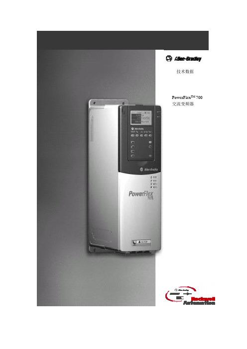
技术数据PowerFlex TM 700交流变频器PowerFlex TM 700交流变频器技术数据正象人们对罗克韦尔自动化产品所期望的那样,PowerFlex 700交流变频器提供了简捷实用的卓越性能。
具有世界级性能的包装结构不仅精巧而且极具竞争价格。
PowerFlex 700交流变频器主要用于控制三相感应电动机,从最简单的速度控制到最苛刻的转矩控制,满足应用系统的要求。
它有两种配置方式:其中标准控制主要是电压/频率(V/f)控制和无速度传感器矢量控制;获得艾伦-布拉德利专利的Force TM技术主要是电压/频率控制、无速度传感器矢量控制和磁场定向控制。
目录说明页码标准的变频器编辑 (3)目录号说明 (5)PowerFlex700变频器…………………………… .6可选件选型 (7)附件 (11)PowerFlex 700可配置的变频器 (14)电源接线 (15)电源端子 (16)控制端子 (19)推荐使用电缆 (23)功率额定值、分支电路保护及功率损耗 (24)最大导线长度 (29)近似尺寸 (31)控制与性能 (36)参数列表 (38)2标准的变频器编辑灵活的包装和安装•IP20,1型——可用于传统方式的控制柜柜内或柜外的安装。
为使安装和可拆卸的进线电缆引入板更易于安装和更换而不影响其它的接线。
•Zero Stacking TM——在环境温度高达500C的情况下,仍允许变频器之间采用零间隙并排式安装。
这种独特的书架式设计允许在访问一个变频器的同时不影响其它的变频器。
节省空间的硬件特性•集成的EMC滤波器附带内置的共模磁心及共模电容器,它提供了一个紧凑的、集于一体的完整解决方案,用以满足EMC要求,包括欧洲的CE标准。
•内部通讯允许用户将变频器集成到制造过程中。
所有内部通讯选项的状态指示器在面板上都是可见的,易于设置和监视变频器的通讯。
当用户进行控制、组态和采集数据的时候,可以很容易地管理从车间底层到企业顶层的信息并无缝地将它们集成为一个完整的系统。
XL7007规格书(中文版).
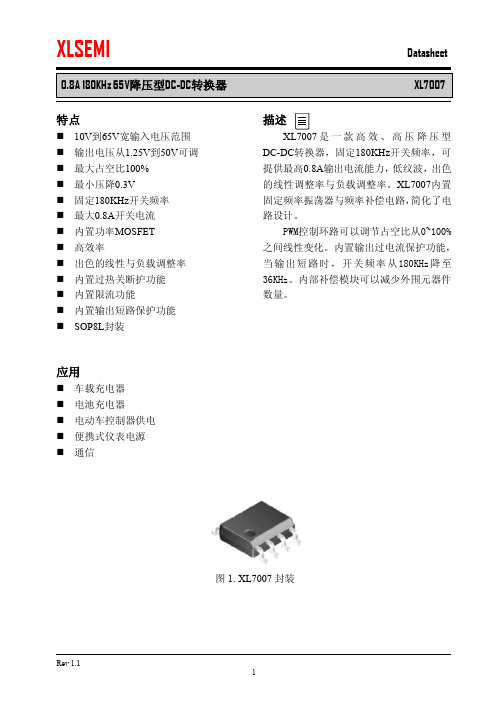
特点n 10V 到65V 宽输入电压范围 n 输出电压从1.25V 到50V 可调 n 最大占空比100% n 最小压降0.3V n 固定180KHz 开关频率 n 最大0.8A 开关电流 n 内置功率MOSFET n 高效率n 出色的线性与负载调整率 n 内置过热关断护功能 n 内置限流功能 n 内置输出短路保护功能 n SOP8L 封装应用n 车载充电器 n 电池充电器 n 电动车控制器供电 n 便携式仪表电源 n 通信描述XL7007是一款高效、高压降压型DC-DC 转换器,固定180KHz 开关频率,可提供最高0.8A 输出电流能力,低纹波,出色的线性调整率与负载调整率。
XL7007内置固定频率振荡器与频率补偿电路,简化了电路设计。
PWM 控制环路可以调节占空比从0~100%之间线性变化。
内置输出过电流保护功能,当输出短路时,开关频率从180KHz 降至36KHz 。
内部补偿模块可以减少外围元器件数量。
图1. XL7007封装0.8A 180KHz 65V降压型DC-DC转换器XL7007 引脚配置图2. XL7007引脚配置表1.引脚说明引脚号引脚名描述1 NC 无连接。
2 FB 反馈引脚,通过外部电阻分压网络,检测输出电压进行调整。
参考电压为1.25V。
3 VC 内部电压调节旁路电容,需要在VC与VIN之间并联1uF电容。
4 VIN 电源输入引脚,支持DC10V~65V范围电压输入,需要在VIN与GND之间并联电解电容以消除噪声。
5,6 SW 功率开关输出引脚,SW是输出功率的开关节点。
7,8 GND 接地引脚。
0.8A 180KHz 65V降压型DC-DC转换器XL7007 方框图图3. XL7007方框图典型应用图4. XL7007系统参数测量电路0.8A 180KHz 65V降压型DC-DC转换器XL7007 订购信息产品型号打印名称封装方式包装类型XL7007E1 XL7007E1 SOP-8L 2500只每卷XLSEMI无铅产品,产品型号带有“E1”后缀的符合RoHS标准。
PowerMark 静态激光打标机说明书

PowerMark静态激光打标机说明书目录1概述 (1)1.1软件简介 (1)1.2软件功能 (1)1.3界面描述 (1)2文件菜单 (2)2.1新建 (2)2.2打开 (3)2.3另存为 (4)2.4保存 (4)2.5导入/导出文档 (5)2.6导入/导出字体 (5)2.7导入/导出图片 (5)2.8导入/导出矢量图 (5)2.9导入/导出数据库 (5)2.10导入/导出打标记录 (5)3视图 (6)4编辑菜单 (7)4.1复制 (7)4.2粘贴 (7)4.3多重复制 (8)4.3.1矩形排列 (9)4.3.2圆形排列 (11)4.4相对复制 (12)4.5删除 (12)4.6撤销 (12)4.7重做 (13)4.8群组/分离群组 (13)4.9组合/分离组合 (13)4.10转为曲线 (14)4.11阵列 (14)4.12填充 (14)4.13变换 (16)4.14分布 (18)4.15排序 (19)4.16线条优化 (19)4.17创建多点 (20)4.18去除交叉点 (20)4.19等宽设定 (21)4.20等高设定 (21)4.21转为虚线 (21)4.22修剪 (21)4.23造形 (22)4.24偏移 (22)5工具栏 (23)5.1移动到中心 (23)5.2视图 (23)5.3登录 (23)5.4隐藏快速工具栏 (23)5.5帮助 (24)6设置菜单 (25)6.1激光校正 (26)6.2多点校正 (31)6.3红光校正 (32)6.4激光参数 (33)6.4.1光纤激光器 (33)6.4.2CO2激光器 (35)6.4.3YAG(紫外)激光器 (37)6.4.5SPI激光器 (44)6.4.6激光器状态提示 (45)6.5激光测试 (45)6.6IO配置 (46)6.6.1端口解释 (47)6.6.2输入端口说明 (47)6.6.3输出端口说明 (48)6.6.4调试IO口 (49)6.6.5DB15扩展IO口说明 (49)6.6.6CON5接线口说明 (51)6.7扩展轴参数配置 (51)6.8系统 (52)6.9串口 (55)6.9.1默认协议 (56)6.9.2字符流协议 (56)6.9.3调试模式 (56)6.10网络通讯 (56)6.10.1以太网 (57)6.10.2Wifi (57)6.10.3通讯协议 (57)6.10.4调试模式 (58)6.10.5网页服务 (58)6.11Modbus设置 (58)6.11.1网络 (58)6.11.2串口 (59)6.12打标高级设置 (59)6.13资源管理/升级 (60)6.14备份/还原 (61)6.14.2一键系统备份/还原 (61)6.15打标记录管理 (62)6.16权限 (62)6.17触摸校正 (63)6.18模块管理器 (63)6.19关于 (63)7扩展菜单 (64)7.1旋转轴 (65)7.2条码打印 (67)7.3一维平面拼接 (68)7.4字体编辑器 (69)7.5IC芯片打标 (69)7.6多文档打标 (69)7.7条码扫描验证 (71)7.8电路板打码&验码 (72)7.9激光清洗 (72)7.10笔号分组打标 (73)7.11简易主页 (74)7.12事件管理器 (74)7.13扩展轴调试 (75)7.14文件队列打标 (76)7.15多卡打标 (76)7.16二维分拆打标 (76)7.17通讯配置管理器 (77)7.18投影标刻 (77)7.19服务器缓存记录打标 (77)7.20WebServer设置 (78)8绘制和对象属性栏 (79)8.1点 (79)8.2直线 (79)8.3矩形 (80)8.4椭圆 (81)8.5曲线 (82)8.6多边形 (82)8.7矢量图 (83)8.8普通文本 (83)8.9组合文本 (85)8.9.1静态文本 (87)8.9.2时间 (87)8.9.3日期 (87)8.9.4扫描枪 (87)8.9.5序列号 (88)8.9.6数据库 (89)8.9.7换行符 (90)8.9.8挂接文本 (90)8.9.9随机码 (90)8.9.10串口通讯 (90)8.9.11网络通讯 (90)8.10图片 (90)8.11条形码/二维码 (91)8.12延时器 (94)8.13VIN码 (94)8.14螺旋线 (94)8.15焊接线 (95)8.16控制点 (95)8.17标尺 (96)9对象列表 (98)10笔号属性栏 (99)10.1笔号属性 (99)10.2参数管理器 (104)11打标控制栏 (106)12状态栏 (108)13输入法 (109)14工具 (110)14.1记事本 (110)14.2转码工具 (110)14.3计算器 (110)14.4端口占用查看器 (110)14.5快速属性编辑器 (110)14.6序列号生成数据库 (110)14.7加工计数器 (110)14.8串口调试助手 (111)14.9网络调试助手 (111)14.10IO口调试 (111)1概述1.1软件简介1.2软件功能1.3界面描述图1-12文件菜单文件菜单实现了常规的文档操作,包括新建、打开、另存为、保存和资源导入导出等。
飞马X7P 操作指南说明书
X7P 操作指南
飞行器内置指南针,它能确保飞行器在智能飞行时保持准确的航向。每次使用前必须检查指南 针状况。
○ 若有如下情景,请重新校准飞行器指南针: 1) 在新的飞行场地飞行前; 2) 飞行器状态指示灯指示指南针异常时; 3) APP 及飞行器提示校准指南针时; 4) 悬停或飞行过程中严重漂移时。
说明:自主飞行是指飞行器不依赖用户操控而进行的飞行,其通过自带的 GPS 定位系统获取位置数据 而进行的飞行动作。例如自动返航、一键返航、指点飞行及环绕模式飞行等等。
4 关于自动返航功能
当飞行器起飞前进入 GPS 定位模式后,飞行器内置的 GPS 设备能自动记录起飞点。飞行器默认 记录此时的地点为返航点。当在以下情况时,飞行器将自动返航:
在飞行过程中,确保飞行器在目视范围内飞行,切勿飞到障碍物(如建筑物、树木等)的背面。 障碍物将遮挡信号,导致飞行器与遥控器失联,进而引发飞行器进入自动返航模式。这样,将导致 飞行器在自动返航过程中撞击障碍物而发生事故。
5 飞行器电池低电量报警及保护功能
1) 关于低电量自动返回功能: 飞行过程中,当飞行器电池低电量时,飞行器状态指示灯变为红色慢速闪烁,APP 同时给出提示。行器即自动返航。 2) GPS 未定位状态时的失联保护功能
当飞行器未能 GPS 定位且与遥控器中断通讯约两秒后,飞行器将在当前位置自动降落。
7 校准指南针
注意:更换飞行场地后,务必在首次飞行前校准指南针。 使用过程中,如飞行器指示灯为“蓝绿灯交替闪烁”即表示指南针异常,需要校准指南针。 校准时请远离有磁场干扰的环境 , 否则会导致校准失败。
三 免责声明与警告----------------------------7 四 技术支持 -------------------------------------7 五 关于新手模式 -------------------------------7 六 认识飞机 -------------------------------------8
数码彩色多功能机 ApeosPort-IV C5570 C4470 C3370 C2270 说明书

禁止复制请注意法律禁止以下产品的复制:国内及海外银行发行的纸币与硬币,政府发行的有价证券,国家及地方债券票据,未使用的邮票与明信片,法律保护的证明贴纸。
禁止有版权产品的复制 (书籍、音乐、绘画、雕刻、地图、电影、摄影,等等),除了私人用途及在家或在上述限定范围内。
本产品安装有防伪功能。
该功能并非用于防止非法复制。
请务必仔细管理您的设备。
为了您的安全使用使用前请认真阅读产品手册。
应使用合适的电源及电压。
请确保机器接地以避免故障或短路可能会引起的触电。
北京 北京市朝阳区建国路甲92号世茂大厦904室 电话:010-********上海 上海市淮海中路300号香港新世界大厦29F/30F/32F 电话:021-********广州 广州市东风中路410-412号健力宝大厦15楼 电话:020-********深圳 深圳市福田区益田路4068号卓越时代广场32楼01~08、10室 电话:0755-********成都 成都市锦江区滨江东路9号B 座香格里拉中心办公楼6层 电话:028-********沈阳 沈阳市和平区和平南大街2号东宇大厦1305,1306室 电话:024-********天津 天津市南京路75号国际大厦502室 电话:022-********长春 长春市南关区亚泰大街3218号通钢国际大厦A 座21层01室 电话:0431-********青岛 青岛市香港中路61号阳光大厦A 座30层EH 电话:0532-********/69大连 大连市西岗区中山路147号森茂大厦1202E 电话:0411-********/80哈尔滨 哈尔滨市南岗区民益街76号网通广场20楼 电话:0451-********杭州 杭州市潮王路240号银地大厦一层 电话:0571-********武汉 武汉市建设大道568号新世界国贸大厦I 座21层2105-2107室 电话:027-********长沙 长沙市芙蓉区燕山路鸿飞大厦1208,1209号 电话:0731-*******郑州 郑州市中原中路220号裕达国际贸易中心A 座22层2212 电话:0371-********温州 温州市车站大道高联大厦9B3 电话:0577-********合肥 合肥市淮河路303号安徽邮电大厦11层D 座2号 电话:0551-*******南京 南京市汉中路89号金鹰国际商城21层B2-C1座 电话:025-********常州 常州市延陵西路23、25、27、29号投资广场17层1706单元 电话:0519-********无锡 无锡市中山路343号东方广场商务楼11层GH 座 电话:0510-********苏州 苏州市苏州工业园区苏华路2号国际大厦1610单元 电话:0512-********东莞 东莞市南城区元美路8号华凯广场B 座1712 电话:0769-********厦门 厦门市思明区湖东路6号华龙大厦805室 电话:0592-*******福州 福州市五四路国贸广场29楼C1 电话:0591-********西安 西安市南关正街88号长安国际广场B 座1006室 电话:029-********重庆 重庆市渝中区邹容路68号大都会商厦2301室 电话:023-********昆明 昆明市北京路155号附1号红塔大厦1201室 电话:0871-*******乌鲁木齐 乌鲁木齐市中山路86号中泉广场13楼B 座 电话:0991-*******富士施乐在华分支机构富士施乐全国服务热线:800-820-5146 400-820-5146/ApeosPort-IV C5570C4470C3370C2270ApeosPort-IVC5570/C4470/C3370/C2270数码彩色多功能机色彩革命ApeosPort-IV C5570 / C4470 / C3370 / C2270系列规格复印功能AP-IV C5570 AP-IV C4470 AP-IV C3370 AP-IV C2270类型稿台型内存1,5 GB(最大2 GB)硬盘80 GB(可用空间:40 GB)预热时间28 秒以下(室温20。
洛克威爾自動化 PowerFlex 750 系列交流變頻器 技術資料说明书
技術資料PowerFlex 750 系列交流變頻器原始說明主題頁次其他資源2產品概述2認證和規格6設計考量11保險絲及斷路器額定值36電纜考量事項59馬達考量事項61尺寸及重量64變頻器選項1152洛克威爾自動化出版品 750-TD001H-ZC-P - 2013 年 6 月PowerFlex 750 系列交流變頻器其他資源這些文件包含與洛克威爾自動化產品相關的其他資訊。
您可以至以下網址檢視或下載出版品:/literature/。
若要訂購書面的技術文件,請向本地 Allen-Bradley 自動化經銷商或洛克威爾銷售代表洽詢。
產品概述PowerFlex 750 系列是功能強大的交流變頻器系列,不僅易於使用,而且為眾多不同的工業應用系統提供絕佳彈性及效能。
PowerFlex 753 提供的一般用途控制器適用於功率最高達 350HP 及250kW 的應用系統。
PowerFlex 755 提供高達 2000HP 及 1500kW 的最大彈性及效能。
以下是 PowerFlex 750 系列具備的重要功能,善用這些功能所帶來的優勢可大幅提高產能。
•DeviceLogix ™ — 內嵌式控制器技術,支援離散輸出及變頻器控制功能之操作,變頻器更內建離散輸入和變頻器狀態資訊。
•預測診斷系統 — 讓變頻器隨時掌握影響冷卻風扇使用壽命及繼電器輸出的資訊。
此外,亦可編輯變頻器的程式,以監控機器或馬達軸承的運行時間。
•選項卡 — 每個變頻器都具備插槽式架構。
提供兩種產品共通的硬體控制選項,有助您降低庫存及零件的需求。
•安全扭力關斷及安全速度監控 — 可根據您的應用系統需求提供安全層級的選擇。
•通訊 — PowerFlex 755 附帶內建乙太網路連接埠。
可利用通訊模組輕鬆新增乙太網路至 PowerFlex 753。
•I/O — 適用額外類比和離散 I/O 之選項卡。
PowerFlex 753 附帶內建 I/O ,可透過選項卡輕鬆擴充。
LG Digital Signage Contents Player MP700 用户指南说明书

OWNER’S MANUALDIGITAL SIGNAGE CONTENTS PLAYER (Hardware)DIGITAL SIGNAGE CONTENTS PLAYER MP700Please read this manual carefully before operatingthe product and retain it for future reference.TABLE OF CONTENTSReplacing Flash Memory Battery (3)Specifications (4)General Specifications (4)Multi I/O Port (4)Operational Specifications (4)Included in the Box (5)Basic Components (5)Optional Items (5)Connections (6)Front Panel (6)Back Panel (6)Monitor Integration (7)**WS50 Model (7)**WX50MF Model (8)84WS70MS Model (9)In/Out Cable Connection (10)DP to HDMI dongle product list (10)Connecting a Monitor with an RGB Cable (11)Connecting a Monitor with DP(DisplayPort) Cable (13)Connection to Multiple Monitors (17)Frequently Asked Questions (FAQs) (18)Unified Codecs (21)Network Setting (21)23Replacing Flash Memory BatteryThe flash memory battery helps maintain the system (BIOS) settings when the computer is powered off. The flash memory battery is a consumable part.Flash Memory Battery4Resolution Recommended Resolution DP with HBR2: 3840 x 2160 @ 30 Hz DP: 1920 x 1080 @ 60 Hz RGB: 1920 x 1080 @ 60 Hz PowerPower Rating 100-240 V~ 50/60 Hz 1.3 AOperating ConditionSync (H/V)Video LED Normal Mode On/On Active On Deep Sleep Mode (Set = Off)Off/Off Off Off Environmental ConditionsOperating Conditions 5 ℃ to 40 ℃Humidity 10 % to 80 %Storage Conditions-20 ℃ to 60 ℃Humidity5 % to 95 %Operational SpecificationsMulti I/O PortSerial Port One external RS-232C Serial port USB Port USB 2.0 port (x2), USB 3.0 port (x1)LAN Port Intel® 82579 Gigabit Ethernet RGB x1 / DP x4x2 for UHD which is printed with 'HBR2'Mini PCIe Supported LINE OUTSupported6Connections**WX50MF ModelFor proper use, it is recommended to use the basic components provided with the MP700 to attach it to a monitor.In/Out Cable ConnectionTo view images on the monitor that is not connected to the monitor docking port of MP700, you need to con-nect the MP700 to the monitor via an RGB or DP Cable.DP to HDMI dongle product listAs the MP700 does not have an HDMI output port, the DP to HDMI converting dongle that supports UHD output should be used if 4K UHD HDMI output is required. Below are the DP to HDMI dongle vendor/product lists. The sale of the products varies depending on the circumstances of each relevant vendor.● BizLink: KS10047● Wieson Technologies: G9857C219-026-H10Connecting a Monitor with an RGB CableRGB connections does not allow analog video and audio signals to be transferred with one cable. RGB cable connections require an additional audio in cable.Connecting a Monitor with DP(DisplayPort) Cable Attention15Connecting/Disconnecting DP(DisplayPort) Audio Device in Windows Embedded Standard 7P16Connection to Multiple MonitorsConnect the RS-232C Out port of the MP700 to the RS-232C In port of the first monitor (SET ID 1).Connect rest of the monitors using a RS-232C cable. (Be careful about input and output ports.)Multiple monitors can be connected to a single MP700. (The maximum number of monitors connected varies depending on the monitor type.) You can set the tile mode by connecting multiple monitors.( SET ID Max )MP700RS232C Cable( SET ID Max )**WS50**WX50MF181920Unified CodecsYou need to install codecs required to play videos. Video files may require different codecs for playing. Web-sites to download unified codecs are listed below:···Network SettingAs there are various network connection methods, please follow the specifications of your carrier or those of your Internet service provider.1. If you cannot connect to the network, check the following.a. Check whether the network connection tray icon is displayed as shown below.If it is not displayed as above, it indicates that the network cable is not connected correctly or that there is a problem with your network system. In this case, check the network cable connection or contact your network system administrator.b.I f you cannot connect to the network even though the tray icon is correctly displayed, make sure that the IP isset correctly by following the procedure below.● Click the Start buttonv Control Panel Network and Internet Network and Sharing Center and then onthe left menu, click "Change adapter settings".21● Right-click the Local Area Connection icon to open a pop-up menu and go to the "Properties" menu.● In the Properties pop-up, select "Internet Protocol Version 4 (TCP/IPv4)" and double-click it.● Check that the IP is set to "Fixed IP" in the IP settings window.● If IP is set to "Fixed IP", change it to the DHCP setting (Automatic) and re-check the network connection.2. The hub (router/switch) connection may be configured as described below.a. Turn the router power on.b. Connect the router port (excluding the WAN port) and the network port of the MP700 using a network cable.c. As in step "a" of item 1, check if the tray icon is displayed correctly. If it is not displayed correctly, go through thewhole procedure in item 1 to check your network settings.d. If you wish to connect to an external network, connect the external network cable to the WAN port.22Make sure to read the Important Precautions before using the product.Keep the User’s Guide(CD) in an accessible place for furture reference.The model and serial number of the SET is located on the back and one side of the SET. Record it below should you ever need service.WARNING - This is a class A product. In a dome stic e nvironme nt this product may cause radio inte rfe re nce in which case the use r may be re quire d to take ade quate measures.MODEL SERIAL T emporary noise is normal when poweringON or OFF this device.。
BENQ MP770 數位投影機 多媒體教學系列 使用手冊

MP770數位投影機多媒體教學系列使用手冊歡迎使用著作權著作權所有 2006 年,明基電通股份有限公司。
所有權利均予保留。
未經本公司事前書面之許可,本文的任何部分皆不得以任何形式或任何方法,包括電子、機械、磁性、光學、化學、手寫或任何方式予以重製、傳輸、轉譯、儲存於檢索系統或翻譯成任何文字或電腦語言。
免責聲明對於本文之任何明示或默示內容,明基電通股份有限公司不做任何保證,亦拒絕對任何特殊目的之商用性或適用性目的予以保證。
此外,本公司保留修改或變更本文之權利,並且修改或變更內容將不另行通知。
*DLP、Digital Micromirror Device 與 DMD 是德州儀器公司 (Texas Instruments) 的商標。
其他名稱的著作權各歸其公司或組織所有。
目錄重要安全說明 (5)介紹 (9)投影機功能 (9)包裝盒內容 (10)投影機外視圖 (11)控制按鍵與功能 (12)安裝投影機 (17)選擇一個合適的位置 (17)將投影機安裝至天花板的安全注意事項 (18)取得合意的投影尺寸 (19)連線 (22)無線連線 (選購配件) (22)訊號線連接 (22)操作 (31)啟動 (31)使用密碼功能 (32)切換輸入訊號 (34)調整影像 (34)選擇縱橫比 (37)影像最佳化 (38)在高海拔環境中使用 (40)隱藏畫面 (40)PIP (子母畫面) 的操作方式 (41)遙控翻頁操作 (42)鎖定影像 (42)建立您自己的啟動畫面 (42)將投影機的功能表個人化 (43)關閉投影機 (43)操作功能表 (44)維護 (53)投影機保養須知 (53)目錄3燈泡資訊 (56)疑難排解 (62)規格 (64)投影機規格 (64)時序表 (65)尺寸 (66)保固 (67)有限保固 (67)法規聲明 (68)FCC 聲明 (68)EEC 聲明 (68)MIC 聲明 (68)WEEE 指示 (68)4目錄重要安全說明本投影機經設計完成及測試通過,符合資訊科技設備的最新安全標準。
明基(BenQ)MP777教育投影机 白皮书
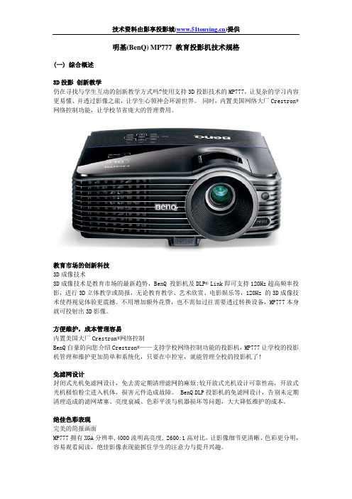
明基(BenQ)MP777 教育投影机技术规格(一)综合概述3D投影创新教学仍在寻找与学生互动的创新教学方式吗?使用支持3D投影技术的MP777,让复杂的学习内容更易懂、并透过影像之旅,让学生心领神会环游世界。
同时,内置美国网络大厂Crestron® 网络控制功能,让学校节省庞大的管理费用。
教育市场的创新科技3D成像技术3D成像技术是教育市场的最新趋势,BenQ 投影机及DLP® Link即可支持120Hz超高频率投影,进行3D立体教学或简报,无论教育教学、艺术欣赏、电影娱乐等,120Hz 的3D成像技术使得视觉体验更震撼。
不用增加额外花费,也不需如过往需要透过转换设备,MP777本身就可投射出3D影像。
方便维护,成本管理容易内置美国大厂Crestron®网络控制BenQ自豪的向您介绍Crestron®——支持学校网络控制功能的投影机,MP777让学校的投影机管理和维护更加简单和系统化,只要在中控室,就能管理全校的投影机了!免滤网设计封闭式光机免滤网设计,免去需定期清理滤网的麻烦:较开放式光机设计可靠性高,开放式光机极怕粉尘进入机体,损害元件造成故障。
BenQ DLP投影机的免滤网设计,告别未定期清理造成的滤网堵塞、亮度衰减、色彩平淡与机器损坏等问题,大大降低维护的成本。
绝佳色彩表现完美的简报画面MP777拥有XGA分辨率,4000流明高亮度, 2600:1高对比,让影像细节更清晰、色彩更分明,容易观看阅读,绝佳影像表现能抓住学生的注意力与提升兴趣。
BrilliantColor™极致色彩科技BenQ投影机拥有独家色轮涂布技术,6节点色轮搭配德州仪器最新影像处理晶片Brilliant Color™技术,Brllianr Color是针对DLP投影机设计,可以大幅提升光使用效率,此外也可以大幅强化投影画面的灰阶表现,并在暗部场景获得最佳的对比表现,并能够在sRGB标准中,及不牺牲绿色色彩的呈现,而让红色及蓝色的色彩饱和度有更佳表现。
GP用户手册

Pro-face GP承蒙使用日本Digital公司Pro-face GP系列触摸屏工业图形显示器产品,万分感谢。
在开始使用GP之前,请认真阅读本手册的有关说明。
本手册对GP产品的硬件特性、连接及初始化设定等内容作介绍。
警告:为了安全、正确地使用该装置,请遵守下列准则。
* 因为存在触电的危险,因此在连接电源线到GP上时,确保电源线没有接通电源。
* 由于GP内部装有高电压部件,当拆解该装置时,可能会引起触电,不要拆解GP。
* 不要使用超过电压范围的电源。
使用超过指定电压范围的电源,可能会损坏GP。
* 在有可燃性气体的环境中不要使用GP,否则可能引起爆炸。
* GP使用一个锂电池用来支持内部时钟数据。
如果错误的更换电池,可能引起爆炸。
为了避免危险,请不要自己更换电池。
当需要更换电池时,请与天任联系。
* 在涉及生命或有重大灾难的情况下,不要使用触摸屏键。
应使用单独的开关。
* 当GP与它的主控制器之间的通信出现错误时,请设计你的系统以便机器动作不会出现错误。
如果不这样,人有受到伤害的危险并且有可能损坏设备。
预防措施:* 不要用硬的或重物碰撞触摸屏,或用太大的力量按触摸屏,因为可能会导致无法修补的损伤。
* 如果放置GP的环境温度超出了规定的温度范围,GP将可能被损坏。
* 在GP的内部,不允许有水、液体或金属物质,否则会使GP损坏或触电。
* 避免减少GP的通风空间,或在易升温的环境中存放、使用GP。
* 避免在阳光直射、灰尘多、肮脏的环境中存放使用GP。
* GP是精密仪器。
注意不要对GP有大的冲击或振动,否则仪器容易损坏。
* 不要使用油漆,有机溶剂或强酸复合物擦拭显示器。
* 因为可能会有无法预料的事情发生,请对您的画面数据做备份。
GP系列触摸屏工业图形显示器用户手册目录第一章技术条件1.1一般规格 ---------------------------------------------------- 4 1.2功能特点 ---------------------------------------------------- 5 1.3GP各部分名称 ----------------------------------------------- 10 1.4外形尺寸 ---------------------------------------------------- 10 第二章安装与接线------------------------------------------------ 12第三章OFF-LINE(离线)方式3.1 进入OFF-LINE方式 ------------------------------------------- 15 3.2 主菜单 ---------------------------------------------------- 16 3.3 初始化—标准操作 -------------------------------------------- 16 3.4 自诊断—标准操作 -------------------------------------------- 16 3.5 画面数据传送 ---------------------------------------------- 17 第四章初始化4.1 初始化屏幕 ------------------------------------------------ 18 4.2 初始化项目 ------------------------------------------------ 18 4.3 系统环境设置 ---------------------------------------------- 19 4.4 I/O设置 -------------------------------------------------- 22 4.5 PLC设置 -------------------------------------------------- 26 4.6 初始化存储器 ---------------------------------------------- 29 4.7 时间设置 -------------------------------------------------- 30 4.8 屏幕设置 -------------------------------------------------- 30 第五章G P运行方式和出错信息5.1 进入运行(RUN)方式 ---------------------------------------- 31 5.2 问题解决 -------------------------------------------------- 31 5.3 自诊断 ---------------------------------------------------- 34 5.4 出错信息 -------------------------------------------------- 37第一章技术条件日本DIGITAL公司的Pro-face GP系列产品,目前有GP70和GP77两大系列。
不容错过的135手动系统——美能达X700
[个人日志] 一篇让我对美能达x700感兴趣的枪文不容错过的135手动系统——美能达X700随着AF的应用,相信坛子里的烧友很少用手动的Minolta X-700了,渐渐地卷入了NCMP的大战。
在这里我想把无忌泡菜曾经谈过的X-700的话题综合起来,便于大家交流,不为别的,就因为他的性价比非常适合于工薪及学生使用,但它决不是一款低档机。
而且它的功能并不见得少,质量也可靠。
有说错之处,请指正。
如果你是一个非常喜欢手动聚焦,并想全程控制曝光的低收入爱好者,我建议你用X-700。
或者你是一个低收入的严肃摄影爱好者,建议你用X-700。
因为X-700能满足你的要求。
首先,价格在1700~1850元间的低价位一般都能接受,当年该机与Nikon FM2一同进入中国时,其价格大约1500元左右,还曾有一段时间价格超过FM2。
毕竟它不是金属机身,也不是纵走钛合金快门,也没有1/250秒的闪光同步,落到今天的地步。
但它的确是一款名机,曾有许多名家认为它是一款够得上专业的专业机。
X-700的黑色外观棱角分明,有一种坚固感,美中不足是它的外壳是非金属的,让人有几分不放心。
它的体积也不大,重量只有505克,右边的小把手小巧不滑,单手握持舒适稳当。
该机的主要功能有手动曝光(MF)、光圈先决(A)、程序自动(P)、TTL闪光、B门等。
(一) 手动曝光使用该挡可全程控制光圈、快门,但它的最快速度只有1/1000秒,与现在的相机比显得不够快,甚至还赶不上凤凰303的1/2000秒。
实际上,在平时1/1000、1/2000秒的快门都很少遇到。
一来,X-700的用家用28-70/3.5-4.5或70-210/4.5-5.6的变焦较多,即使使用f/1.4-f/2的大光圈的镜头,1/1000秒的速度也勉强够用。
二来,普通用家一般选择的胶卷为100/200,1/1000秒也能对付。
个人认为,本着够用的原则,不必去追求平时很少用的功能。
另外,如果你有独立的测光表,想按照独立测光表的曝光值曝光,就得用MF。
MPXV7002DP中文资料

Document Number: MPXV7002Rev 0, 09/2005Freescale Semiconductor Technical Data© Freescale Semiconductor, Inc., 2005. All rights reserved.Integrated Silicon Pressure Sensor On-Chip Signal Conditioned, Temperature Compensated and CalibratedThe MPXV7002 series piezoresistive transducers are state-of-the-artmonolithic silicon pressure sensors designed for a wide range of applications, but particularly those employing a microcontroller or microprocessor with A/D inputs. This transducer combines advanced micromachining techniques, thin-film metallization, and bipolar processing to provide an accurate, high level analog output signal that is proportional to the applied pressure.Features • 2.5% Typical Error over +10°C to +60°C with Auto Zero• 6.25% Maximum Error over +10°C to +60°C without Auto Zero•Ideally Suited for Microprocessor or Microcontroller-Based Systems •Thermoplastic (PPS) Surface Mount Package •Temperature Compensated over +10° to +60°C •Patented Silicon Shear Stress Strain Gauge•Available in Differential and Gauge Configurations Typical Applications•Hospital Beds •HVAC•Respiratory Systems •Process ControlORDERING INFORMATIONDevice TypeOptionsCase No.MPX Series Order No.Packing Options Device Marking SMALL OUTLINE PACKAGE (MPXV7002 SERIES)Ported ElementsGauge, Axial Port, SMT 482A MPXV7002GC6URailsMPXV 7002GGauge, Axial Port, SMT482A MPXV 7002G C6T1Tape & Reel MPXV 7002GGauge, Side Port, SMT 1369MPXV 7002G P Trays MPXV 7002G Differential, Dual Port, SMT1351MPXV 7002DP Trays MPXV 7002G Differential, Dual Port, SMT1351MPXV7002DPT1Tape & Reel MPXV7002G MPXV7002 SERIESINTEGRATED PRESSURE SENSOR -2 to 2 kPa (-0.3 to 0.3 psi)0.5 to 4.5 V OUTPUT SMALL OUTLINE PACKAGEPIN NUMBERS(1)1.Pins 1, 5, 6, 7, and 8 are internal device connections. Do not connect to external circuitry or ground. Pin 1 is noted by the notch in the lead.1N/C 5N/C 2V S 6N/C 3Gnd 7N/C 4V out8N/CSensing ElementThin Film Temperature Compensationand Gain Stage #1Gain Stage #2and Ground Reference Shift CircuitryV SV outGNDPins 1 and 5 through 8 are NO CONNECTS for surface mount packageMPXV7002SensorsFigure 1. Fully Integrated Pressure Sensor SchematicTable 1. Maximum Ratings (1)1.Exposure beyond the specified limits may cause permanent damage or degradation to the device.RatingSymbol Value Unit Maximum Pressure (P1 > P2)P max 8.0kPa Storage Temperature T stg –30 to +100°C Operating TemperatureT A10 to +60°CTable 2. Operating Characteristics (V S = 5.0 Vdc, T A = 25°C unless otherwise noted. Decoupling circuit shown in Figure 3 required to meet specification.)CharacteristicSymbol Min Typ Max Unit Pressure Range (1)1. 1.0 kPa (kiloPascal) equals 0.145 psi.P OP –2.0— 2.0kPa Supply Voltage (2)2.Device is ratiometric within this specified excitation range.V S 4.75 5.0 5.25Vdc Supply Current I o ——10mAdc Pressure Offset (3)(10 to 60°C)@ V S = 5.0 Volts 3.Offset (V off ) is defined as the output voltage at the minimum rated pressure.V off 2.25 2.5 2.75Vdc Full Scale Output (4)(10 to 60°C)@ V S = 5.0 Volts 4.Full Scale Output (V FSO ) is defined as the output voltage at the maximum or full rated pressure.V FSO 4.25 4.5 4.75Vdc Full Scale Span (5)(10 to 60°C)@ V S = 5.0 Volts 5.Full Scale Span (V FSS ) is defined as the algebraic difference between the output voltage at full rated pressure and the output voltage at the minimum rated pressure.V FSS 3.5 4.0 4.5 V Vdc Accuracy (6)(10 to 60°C)6.Accuracy (error budget) consists of the following:•Linearity:Output deviation from a straight line relationship with pressure over the specified pressure range.•Temperature Hysteresis:Output deviation at any temperature within the operating temperature range, after the temperature is cycled toand from the minimum or maximum operating temperature points, with zero differential pressure applied.•Pressure Hysteresis:Output deviation at any pressure within the specified range, when this pressure is cycled to and from theminimum or maximum rated pressure, at 25°C.•TcSpan:Output deviation over the temperature range of 10° to 60°C, relative to 25°C.•TcOffset:Output deviation with minimum rated pressure applied, over the temperature range of 10° to 60°C, relative to25°C.•Variation from Nominal:The variation from nominal values, for Offset or Full Scale Span, as a percent of V FSS , at 25°C.——±2.5(7)7.Auto Zero at Factory Installation: Due to the sensitivity of the MPXV7002 Series, external mechanical stresses and mounting position can affect the zero pressure output reading. Autozero is defined as storing the zero pressure output reading and subtracting this from the device's output during normal operations. Reference AN1636 for specific information. The specified accuracy assumes a maximum temperature change of ± 5°C between autozero and measurement.±6.25%V FSS Sensitivity V/P — 1.0—-V/kPa Response Time (8)8.Response Time is defined as the time for the incremental change in the output to go from 10% to 90% of its final value when subjected to a specified step change in pressure.t R — 1.0—-ms Output Source Current at Full Scale Output I O+—0.1—-mAdc Warm-Up Time (9)9.Warm-up Time is defined as the time required for the product to meet the specified output voltage after the Pressure has been stabilized.——20—-msMPXV7002SensorsON-CHIP TEMPERATURE COMPENSATION, CALIBRATION AND SIGNAL CONDITIONINGThe performance over temperature is achieved by integrating the shear-stress strain gauge, temperature compensation, calibration and signal conditioning circuitry onto a single monolithic chip.Figure 2 illustrates the Differential or Gauge configuration in the basic chip carrier (Case 482). A gel die coat isolates the die surface and wire bonds from the environment, while allowing the pressure signal to be transmitted to the sensor diaphragm.The MPXV7002 series pressure sensor operatingcharacteristics, and internal reliability and qualification tests are based on use of dry air as the pressure media. Media, other than dry air, may have adverse effects on sensorperformance and long-term reliability. Contact the factory for information regarding media compatibility in your application.Figure 3 shows the recommended decoupling circuit for interfacing the integrated sensor to the A/D input of amicroprocessor or microcontroller. Proper decoupling of the power supply is recommended.Figure 4 shows the sensor output signal relative to pressure input. Typical, minimum, and maximum output curves are shown for operation over a temperature range of 10° to 60°C using the decoupling circuit shown in Figure 3. The output will saturate outside of the specified pressure range.Figure 2. Cross-Sectional Diagram SOP(not to scale)Figure 3. Recommended Power Supply Decouplingand Output Filtering(For additional output filtering, please refer toApplication Note AN1646.)Figure 4. Output versus Pressure DifferentialFluoro Silicone Gel Die CoatWire Bond DieP1Stainless Steel CapThermoplasticCaseDie BondDifferential SensingElementP2+5 V1.0 µF0.01 µF470 pFGNDV sV outIPSOUTPUTLead FrameDifferential Pressure (kPa)O u t p u t V o l t a g e (V )5.04.03.02.01.002TYPICALMIN-2-11Transfer Function:V out = V S × (0.2 × P(kPa)+0.5) ± 6.25% V FSS V S = 5.0 Vdc T A = 10 to 60°CMAXMPXV7002SensorsPRESSURE (P1)/VACUUM (P2) SIDE IDENTIFICATION TABLEFreescale designates the two sides of the pressure sensor as the Pressure (P1) side and the Vacuum (P2) side. The Pressure (P1) side is the side containing a gel die coat which protects the die from harsh media.The Pressure (P1) side may be identified by using the table below:MINIMUM RECOMMENDED FOOTPRINT FOR SURFACE MOUNTED APPLICATIONSSurface mount board layout is a critical portion of the total design. The footprint for the surface mount packages must be the correct size to ensure proper solder connection interface between the board and the package. With the correctfootprint, the packages will self align when subjected to a solder reflow process. It is always recommended to design boards with a solder mask layer to avoid bridging and shorting between solder pads.Figure 5. Small Outline Package FootprintPart NumberCase Type Pressure (P1)Side IdentifierMPXV7002GC6U/GC6T1482A-01Vertical Port Attached MPXV7002GP 1369-01Side with Port Attached MPXV7002DP1351-01Side with Dual Port Attached0.66016.760.060 TYP 8X 1.520.100 TYP 8X 2.540.100 TYP 8X 2.540.3007.62inch mmSCALE 2:1PACKAGE DIMENSIONSISSUE ASMALL OUTLINE PACKAGEMPXV7002 SensorsCASE 1351-01ISSUE ASMALL OUTLINE PACKAGEMPXV7002SensorsCASE 1351-01ISSUE ASMALL OUTLINE PACKAGEMPXV7002 SensorsCASE 1369-01ISSUE BSMALL OUTLINE PACKAGEMPXV7002SensorsCASE 1369-01ISSUE BSMALL OUTLINE PACKAGEMPXV7002 SensorsMPXV7002Rev. 0How to Reach Us:Home Page: E-mail:support@USA/Europe or Locations Not Listed:Freescale SemiconductorTechnical Information Center, CH3701300 N. Alma School Road Chandler, Arizona 85224+1-800-521-6274 or +1-480-768-2130support@Europe, Middle East, and Africa:Freescale Halbleiter Deutschland GmbH Technical Information Center Schatzbogen 781829 Muenchen, Germany +44 1296 380 456 (English)+46 8 52200080 (English)+49 89 92103 559 (German)+33 1 69 35 48 48 (French)support@Japan:Freescale Semiconductor Japan Ltd.Headquarters ARCO Tower 15F1-8-1, Shimo-Meguro, Meguro-ku,Tokyo 153-0064Japan0120 191014 or +81 3 5437 9125support.japan@Asia/Pacific:Freescale Semiconductor Hong Kong Ltd.Technical Information Center 2 Dai King StreetTai Po Industrial Estate Tai Po, N.T., Hong Kong +800 2666 8080@For Literature Requests Only:Freescale Semiconductor Literature Distribution Center P .O. Box 5405Denver, Colorado 802171-800-441-2447 or 303-675-2140Fax: 303-675-2150LDCForFreescaleSemiconductor@Information in this document is provided solely to enable system and software implementers to use Freescale Semiconductor products. There are no express or implied copyright licenses granted hereunder to design or fabricate any integrated circuits or integrated circuits based on the information in this document.Freescale Semiconductor reserves the right to make changes without further notice to any products herein. Freescale Semiconductor makes no warranty, representation or guarantee regarding the suitability of its products for any particular purpose, nor does Freescale Semiconductor assume any liability arising out of the application or use of any product or circuit, and specifically disclaims any and all liability, including without limitation consequential or incidental damages. “Typical” parameters that may beprovided in Freescale Semiconductor data sheets and/or specifications can and do vary in different applications and actual performance may vary over time. All operating parameters, including “Typicals”, must be validated for each customer application by customer’s technical experts. Freescale Semiconductor does not convey any license under its patent rights nor the rights of others. Freescale Semiconductor products are not designed, intended, or authorized for use as components in systems intended for surgical implant into the body, or other applications intended to support or sustain life, or for any other application in which the failure of the Freescale Semiconductor product could create a situation where personal injury or death may occur. Should Buyer purchase or use Freescale Semiconductor products for any such unintended orunauthorized application, Buyer shall indemnify and hold Freescale Semiconductor and its officers, employees, subsidiaries, affiliates, and distributors harmless against all claims, costs, damages, and expenses, and reasonable attorney fees arising out of, directly or indirectly, any claim of personal injury or death associated with such unintended or unauthorized use, even if such claim alleges that Freescale Semiconductor was negligent regarding the design or manufacture of the part. Freescale™ and the Freescale logo are trademarks of Freescale Semiconductor, Inc.All other product or service names are the property of their respective owners.© Freescale Semiconductor, Inc. 2005. All rights reserved.。
海西汽车产品介绍

700P轻卡(工程车)简介编写:浪蝶狂蜂 QQ11855546942012主销车型一.轻卡定义:轻卡是指车长小于6米的载货汽车。
总质量小于4500kg。
以柴油机为动力,最高设计车速不大于70km/h,最大设计总质量不大于4500kg,长不大于6m,宽不大于2m,高不大于2.5m,具有四个车轮的货车。
发动机我们一般使用4108(含)以下型号的发动机。
工程车带有车厢举升机构。
1.上户必备公告:工信部底盘、整车公告。
交通部燃油排放达标,3C认证,局部区域要求的环保公告。
2.上户不可变通参数:轴距、整车长宽高尺寸,车身(驾驶室)外观,局部区域的整备质量要求。
3.轻卡(工程车)用户的特点、使用范围:中短途用车。
主要用于矿山、工地、大工程的配套、山上竹木运输及乡镇货物运输。
已代替低速货车车型。
用户要求:价廉物美、经济适用、服务及时。
情感销售、“跟风”较普遍。
多数无需贷款。
故以乡镇个体购买为主体,不像中、重卡系统,大客户多。
二、700p公告、配置表。
车辆型号ZZ1048D18CB0 外型尺寸(长×宽×高)(mm)5995×2060,1960×2560 发动机型号CA498E3-10 YN33PE-1 发动机功率78、76发动机排量3168、3298 燃烧种类柴油总质量(Kg) 3940 载质量利用系数0.75整备质量(kg)2250 额定载质量(kg) 1495轴距(mm) 3360 最高车速 (km/h) 90前悬/后悬(mm) 前1175 弹簧片数3/5+3 9/10+8 后1460 轮胎数 6接近角/离去角24/15 轮胎规格7.00-16LT6PR 7.00R16LT6PR 轴荷1420/2520 转向形式方向机前轮距15701730 后轮距15401485底盘依据标准GB17691-2005国Ⅲ,GB3847-2005车辆型号ZZ3048E18CB0 外型尺寸(长×宽×高)(mm)5995×2380×2850发动机型号YC4D130-33 YN38PE-1 发动机功率96 85发动机排量4214 3760 燃烧种类柴油总质量(Kg) 4290 载质量利用系数0.65整备质量(kg)2600 额定载质量(kg) 1495轴距3350 最高车速 (km/h) 85前悬/后悬(mm) 前1260 弹簧片数9/11+8 后1385 轮胎数 6接近角/离去角24/15 轮胎规格7.50-16 6PR 7.50R16 6PR 轴荷1560/2730 转向形式方向机前轮距1750 后轮距1720,1650 底盘依据标准GB17691-2005国Ⅲ,GB3847-2005车辆型号ZZ3068E18CB0 外型尺寸(长×宽×高)(mm)6800,6450×2380×2880发动机型号YC4D130-33 YC4E135-33 发动机功率96 100发动机排量4214 3760 燃烧种类柴油总质量(Kg) 5569 载质量利用系数0.65整备质量(kg)3375 额定载质量(kg) 1999轴距3350 3650 最高车速 (km/h) 85前悬/后悬(mm) 前1260 1740 弹簧片数9/11+8 后1260 1540 轮胎数 6接近角/离去角24/15 轮胎规格 8.25-16 轴荷1560/2730 转向形式方向机前轮距1750 后轮距1720,1650 底盘依据标准GB17691-2005国Ⅲ,GB3847-2005车辆型号ZZ3128G17CB0 外型尺寸(长×宽×高)(mm)发动机型号YC4E160-33 发动机功率118 发动机排量4260 4214 燃烧种类柴油总质量(Kg) 5569 载质量利用系数0.65 整备质量(kg)3375 额定载质量(kg) 4999 轴距3800 最高车速 (km/h) 85前悬/后悬(mm) 前1260 弹簧片数9/11+8 后1385 轮胎数 6接近角/离去角24/16 24/17 轮胎规格9.00-20 轴荷2110/3459 转向形式方向机前轮距1750 后轮距1720 底盘依据标准GB17691-2005国Ⅲ,GB3847-2005中国重汽集团福建海西汽车有限公司700P车型正侧面展示图:驾驶室工程车型谱车型F7-1880-1(公告:3048/低速汽车)F7-1880-2(轴距:3350,公告:3048/低速汽车),F7-1880-3(轴距:3650,公告:3048)轴距mm 3350 3350 3650 3350 3650 驾驶室F7-1880排半(驾驶室为全金属封闭式,车头平头排半,可翻转,乘员3人,驾驶室内部宽度:1880mm)底盘发动机(功率KW)YN4102QB(70)带140离合器壳,325膜片YN38PE-1(85)缸径:102带140离合器壳,325膜片YC4D130-33(96)(选 YC4E135-33(100),2080驾驶室)带140离合器壳,325膜片(轴肩式)变速器145QF慢档(低速汽车用三齿、汽车用万里扬)6T-53HF 选HW50508 HW90710快档(后桥速比:6.33)散热器/中冷器铝质、散热面积18.32㎡铝质、散热面积21.12㎡、带中冷器铝质、散热面积21.12㎡、带中冷器前/后桥及轴荷1069(2t、轮距1750)/1069(5t、轮距1630),选1080(2.5t)/1080N(8t)低速汽车用万腾桥1080(2.5t)/1080N(8t)选145主减(9t)1090N(3t)/145N(1650轮距、9t)1090N(3t)/145N(1650轮距、9t)或145(3.6t)/153G(10t)1080(2.5t)/1080N(8t)选145主减(9t)1090N(3t)/145N(1650轮距、9t)1090N(3t)/153G(10t)1090N(3t)/145N1(1725轮距、9t)或145(3.6t)/153G(10t)轮胎及轮辋8.25-16(轮辋:6.5-16),选装8.25-16(轮8.25-20(轮辋:9.00-20(轮辋:7.00T-9.00-20(轮辋:8.25-16(轮8.25-20(轮辋:6.5-9.00-20(轮辋:7.00T-9.00-20(轮辋:9.00-20(轮辋:7.50-16(轮辋:6.00G-16)辋:6.5-16) 6.5-20)20 7.00T-20 辋:6.5-16) 20)20 7.00T-20 7.00T-20车架250×10主副一体、车架宽800250×10主副一体、车架宽800250×10主副一体、车架宽800280×10主副一体或250×10整体车架(带副梁)、车架宽800250×10主副一体280×10主副一体或250×10整体车架(带副梁)、车架宽800悬架前: 1061(11×9-75)/后:140(13×11-75+11×8-75)前: 1061(11×9-75)/后:140(13×11-75+11×8-75)前: 1061(13×9-75)/后:140(15×11-75+13×8-75)前: 1061(13×9-75)/后:140(15×11-75+13×8-75)前: 1061(11×9-75)/后:140(13×11-75+11×8-75)前: 1061(13×9-75)/后:140(15×11-75+13×8-75)前: 153(13×9-90)/后:140-2/153(15×11-90+13×8-90)前: 1061(13×9-75)/后:140(15×11-75+13×8-75)前: 153(13×9-90)/后:140-2/153(15×11-90+13×8-90)货箱规格m 3.85×2.2×0.6/0.8/(0.6+0.2)工程货箱3.85×2.2×/0.8/(0.8+0.2)工程货箱4.2×2.2×/0.8/(0.8+0.2)工程货箱3.85×2.2×/0.8/(0.8+0.2)工程货箱4.2×2.2×/0.8/(0.8+0.2)工程货箱标配直筋、底板4mm、边板3㎜。
雅马哈灰熊700F1 YFM7FGPW用户使用说明书2

(图见原文)1.点火保险2.大灯保险3.四轮驱电机保险4.散热器风扇保险5.信号系统保险6.辅助DC插座保险7.备用保险总保险、喷油系统保险、EPS保险及保险盒位于控制板A 下。
(参见第8-8页)如保险烧断,则按下列步骤进行更换:1.将钥匙旋至“OFF”(关闭),关闭所有电气线路。
ECB00640CAUTION:(小心)为避免偶然短路,检查或更换保险时应关闭总开关。
2.取下烧断保险丝,然后按规定电流装入新保险。
8-57规定保险:总保险:40.0A大灯保险:15.0A点火保险:10.0A四轮驱电机保险:10.0A信号系统保险:5.0A辅助DC插座保险:15.0A散热器风扇保险:15.0A燃油系统保险:15.0AEPS保险:40.0AEWB02171WARNING(警告)务必使用规定功率的保险,切勿使用其他替代物。
使用不合适的保险丝或取代物会损坏电气系统,导致火灾。
3.将钥匙旋至“ON”,开启电气线路,检查是否所有设备都在运行。
4.如保险马上再次烧断,则请雅马哈经销商检查电气系统。
EBU27440更换大灯灯泡:如大灯灯泡烧坏,则按以下步骤进行更换:1.拔出大灯后部的灯盖,将其拆除。
(图见原文)1.大灯后部灯盖8-582.取下大灯灯泡盖。
(图见原文)1.大灯灯泡盖3.断开大灯耦合器。
(图见原文)1.大灯耦合器4.解开大灯灯泡座,取下烧坏的灯泡。
8-59(图见原文)1.大灯灯泡座2.大灯灯泡EWB02220WARNING(警告)大灯灯泡点亮时及关闭后不久灯泡很烫。
触摸或取灯泡前要等灯泡冷却。
如灯泡触及易燃物,则可能烧伤或发生火灾。
5.装入新大灯灯泡,然后拧入灯泡座。
(图见原文)1.切勿触摸灯泡玻璃部分。
ECB00650WARNING(警告)切勿触及大灯灯泡玻璃部分,让其远离油,否则玻璃透明度、灯泡发光度及灯泡寿命都会受到很大的影响。
用蘸有酒精或稀释剂的抹布擦净大灯灯泡上的脏物及指痕。
6.连接大灯耦合器。
SONY PDW-700 说明书
第 4 章 : 拍摄
使用光盘 .......................................................................................... 用于记录和播放的光盘................................................................. 使用时的注意事项......................................................................... 写保护光盘..................................................................................... 装入和取出光盘............................................................................. 格式化光盘..................................................................................... 当记录非正常结束时的光盘处理 (恢复功能) ......................... 58 58 58 58 58 60 60
第 1 章 : 概述
特点.................................................................................................... 9 部件及控件的位置和功能 ................................................................. 电源................................................................................................. 附件连接......................................................................................... 操作和接口部分............................................................................. HDVF-20A 取景器 (选购) ......................................................... 取景器屏幕上的状态显示............................................................. 10 10 11 12 23 24
迪克森 PRO 700DX 三轴平台头说明书
This product is designed to withstand equip-ment up to 5kgs. Please do not use equipment exceeding this limit.Equipment with uneven weight distribution should not be panned by the Quick Shoe.A loose mounting screw may go unnoticed, and result in a sudden accidental fall.Carrying a tripod with a camera left on can result in unexpected accidents. We therefore,recommend that you remove your camera when carrying the tripod.G273-1SpecificationLength folded760mm (29 11/12")Max. operating height 1,900mm(74 5/6")Max. center column ext.380mm(14 11/12")Weight 3.53kg(7lbs 13oz)BALL HEAD 800QUICK SHOE(U3/8")Cat. No. 618-340THREAD ADAPTER SET Cat. No. 618-331Loosen the Center Column Stopper and the Locking Collar, and then pull out the Center Column.By inverting the Center Column, it is possible to do copy, and close up work.Insert the Center Column from the lower side of Main Body, and tighten the Locking Collar and the Center Column Stopper.Printed in Thailand.Always remove the Pan Head when replacing the Center Column.Remove the Center Column Base Stopper truning to the way of arrow.CautionThe Pan Head fixing screw is reversible for either large thread (U3/8) or small thread (U1/4).1. Move the Plate Cover down.2. Loosen the small screw in about three turnings with an Allen wrench (2mm width).3. Loosen the Plate without removing the small screw.U3/8U1/4Plate CoverSmall Screw Plate 4. Loosen the Pan Head fixing screw and pull it out. Then, screw it in again after reversing top and bottom.5. Adjust the height of screw in approx. 8mm above the Plate and then,tighten the small screw by an Allen wrench.6. Put the Plate Cover back.Be sure to open all three legs completely in order to prevent camera shaker, or accidental tip overs caused by unstableness.SLIK CORPORATION853 Kayama, Hidaka City, Saitama 350-1231, JapanPhone 81-42-989-2141, Fax. 81-42-985-0210 ©2007Attach the two Pan Handles to the Pan Head, by inserting the shorter handle to the left, and the longer horizontal tilt handle to the right.Do not reverse.Remove Quick Shoe by opening the LockingLever and then pressing the Release Button.Screw Quick Shoe on to camera, and insertback into the Camera Platform.Please DO Not over tight your Quick Shoe.Correctly installed you will hear a "click", andthe Quick Shoe will rotate 360°.Adjusting the firmness of theLocking LeverFix the Quick Shoe at a desired position by closingthe Locking Lever.After long use, you may need to re-tighten theLever Lock mechanism through the windowlocated underneath the Pan Head.First, you will need to loosen the locking pinwith an ordinary allen wrench(1.5 mm).We advise you not to tamper with this part untilit becomes necessary.Two bubble levels are built-in for vertical andhorizontal positioning.Bubble levels Safeguards during operation with a CameraThe camera may fall suddenly when theLocking Lever is loosened, causing damagesand injuries. Always hold on to the camera dur-ing such operation.When loosening either the Pan & Tilt Handle, orthe Vertical Tilt Handle, take precaution by keep-ing a firm grip on the handle until the Pan Head islocked down.Using the Pan HeadLoosen the Pan & Tilt Handle, and the headwill tilt back and forth.Loosen the Panning Lock Knob, and the head willrotate along the horizontal direction.CautiontightenloosenCautionPlease exchange by the following method to attach other heads or acces-sories to this leg. Fix the Center Column of the legs firmly by both theCenter Column Locking Collar and the Center Column Stopper. Next,tighten the Panning Lock Knob of the head firmly. The Pan & Tilt Handleand the Vertical Tilt Handle are grasped and then, turn the head counter-clockwise forcibly. The head loosens now.Set the new head, or accessory on the tripod's threaded post, and turnclockwise until it comes to a stop. Tighten the Panning Lock Knob andturn clockwise slightly more.Do not attach camera directly to the threaded post of the Center Column.This can damage both camera and tripod.When attaching the Pan Head to a tripod with asmall thread(U1/4) use the optional smallthread adapter.To avoid unnecessary camera vibrations, try tokeep the Center Column height to a minimum.Also use the larger legs first, when extendingthe legs.Flip up the Leg Lock Lever to extend or shortenany of the individual leg sections to the desiredlength, and press the Leg Lock Lever flushagainst the Leg to lock.You can get lower height.You may injure your hand by a sudden fall, ifyou let go of Pan Head before locking theCollar.Turn the Locking Collar with your fingers on theside of the Collar.CautionProhibitionHold onto the Pan Head with one hand, andloosen the Center Column Stopper and the CenterColumn Locking Collar with the other hand.Raise or lower Pan Head to desired height, andwhile maintaining a hold of the Pan Head, tightenthe Locking Collar and the Stopper.Remove the Center Column Base Stopper andthen, remove the Lower part of Center Column.Put the Center Column Base Stopper on theUpper part of Center Column.。
多功能焊接重工站说明书
MP740070MP740071MP740072Single and Dual Channel Soldering Rework Stations /multicomp-pro/multicomp-proFeatures• User friendly operator interface and big number display.• Automatic recognition of the tools connected to the rework station.• Three user defined temperature set points.• Two output channels can work at the same time. Only for MP740069.Part Number MP740068&MP740149MP740150MP740069Rated Working Voltage230V AC ±10% 50Hz / 110V AC ±10% 60Hz Rated Power150W200W200WTemperature Range150°C to 480°C / 302°F to 896°F (Configurable temperature range depends on the connected accessories of the soldering handle)Temperature Accuracy±8°C / ±15°F Temperature Stability±2°C / ±4°FChannels12 Functional Ground Connection 3.5mm plugStand-by and Auto-sleep Mode SupportedDisplay Resolution240 × 160 Dots (white letters on blue) Operating Temperature0°C to +40°C Relative humidity <80% Storage Temperature-20°C to +80°C Relative humidity <80% Dimension315mm (L) ×252mm (W) ×127mm (H) Weight Approximately 4kgAccessories Main Unit, Manual,Power Cord (UK/EU/US),Iron Stand,130W Soldering Iron (MP740071)3.5mm grounding-type receptacleMain Unit, Manual,Power Cord (UK/EU),Iron Stand,130W Soldering Iron (MP740071),100W Tweezer type Soldering Iron (MP740073)SpecificationsSingle Channel Dual ChannelSingle and Dual Channel Soldering Rework Stations/multicomp-pro /multicomp-proReplacement PartsMP740070 -50W Mini Soldering IronMP740071 - 130W Soldering IronMP740072 - 150W High-power Soldering IronMP740073 - 100W Tweezer type Soldering IronConical MP740218Chisel MP740219Chisel MP740220Pointed MP740222Knife MP740223Chisel MP740221Images and Diagram for Replacement Tips used with MP740070 - 50W Mini Soldering IronDimensions : MillimetresChiselMP740219ChiselMP740220ChiselMP740221PointedMP740222ConicalMP740218KnifeMP740223Single and Dual Channel Soldering Rework Stations/multicomp-pro /multicomp-proImages and Diagram for Replacement Tips used with MP740071 - 130W Soldering IronKnife MP740237Pointed-Bent MP740236Pointed MP740235Knife MP740234Pointed MP740233Pointed MP740232Chisel MP740231Chisel MP740230Chisel MP740229Chisel MP740228Conical MP740227Conical MP740226Conical MP740225Conical MP740224Dimensions : MillimetresConicalMP740224ConicalMP740225ConicalMP740226ConicalMP740227ChiselMP740228Chisel MP740229Chisel MP740230Chisel MP740231Pointed MP740232PointedMP740233Knife MP740234Pointed MP740235Pointed-Bent MP740236KnifeMP740237Single and Dual Channel Soldering Rework Stations/multicomp-pro /multicomp-proImages and Diagram for Replacement Tips used with MP740072 - 150W High-power Soldering IronImages and Diagram for Replacement Tips used with MP740073 - 100W Tweezer type Soldering IronConical MP740238Conical MP740239Conical MP740240Conical MP740245Chisel MP740241Chisel MP740242Chisel MP740243KnifeMP740244Conical MP740238Conical MP740239Conical MP740240ConicalMP740245ChiselMP740241ChiselMP740242ChiselMP740243KnifeMP740244Tweezer MP740246TweezerMP740247TweezerMP740248Dimensions : MillimetresSingle and Dual Channel Soldering Rework Stations /multicomp-pro/multicomp-proTweezer MP740246Tweezer MP740247Tweezer MP740248Part Number TableDescription Part NumberSingle Channel Soldering Rework Station, 150W, UK/EU Plug MP740068Single Channel Soldering Rework Station, 150W, US Plug MP740149Single Channel Soldering Rework Station, 200W, US Plug MP740150Dual Channel Soldering Rework Station, 200W, UK/EU Plug MP74006950W Mini Soldering Iron MP740070130W Soldering Iron MP740071150W High Power Soldering Iron MP740072100W Tweezer type Soldering Iron MP740073Soldering Iron Tip with Integrated Heater, 50W, 1.2mm, Conical for MP740070MP740218Soldering Iron Tip with Integrated Heater, 50W, 1.3mm, Chisel for MP740070MP740219Soldering Iron Tip with Integrated Heater, 50W, 2.2mm, Chisel for MP740070MP740220Soldering Iron Tip with Integrated Heater, 50W, 3mm, Chisel for MP740070MP740221Soldering Iron Tip with Integrated Heater, 50W, 0.5mm, Pointed for MP740070MP740222Soldering Iron Tip with Integrated Heater, 50W, Knife for MP740070MP740223Soldering Iron Tip with Integrated Heater, 130W, 1.2mm, Conical for MP740071MP740224Soldering Iron Tip with Integrated Heater, 130W, 2.4mm, Conical for MP740071MP740225Soldering Iron Tip with Integrated Heater, 130W, 3.2mm, Conical for MP740071MP740226Soldering Iron Tip with Integrated Heater, 130W, 4.6mm, Conical for MP740071MP740227Soldering Iron Tip with Integrated Heater, 130W, 1.6mm, Chisel for MP740071MP740228Soldering Iron Tip with Integrated Heater, 130W, 2.4mm, Chisel for MP740071MP740229Soldering Iron Tip with Integrated Heater, 130W, 3.2mm, Chisel for MP740071MP740230Soldering Iron Tip with Integrated Heater, 130W, 4.6mm, Chisel for MP740071MP740231Dimensions : MillimetresSingle and Dual Channel Soldering Rework Stations/multicomp-pro /multicomp-proImportant Notice : This data sheet and its contents (the “Information”) belong to the members of the AVNET group of companies (the “Group”) or are licensed to it. No licence is granted for the use of it other than for information purposes in connection with the products to which it relates. No licence of any intellectual property rights is granted. The Information is subject to change without notice and replaces all data sheets previously supplied. The Information supplied is believed to be accurate but the Group assumes no responsibility for its accuracy or completeness, any error in or omission from it or for any use made of it. Users of this data sheet should check for themselves the Information and the suitability of the products for their purpose and not make any assumptions based on information included or omitted. Liability for loss or damage resulting from any reliance on the Information or use of it (including liability resulting from negligence or where the Group was aware of the possibility of such loss or damage arising) is excluded. This will not operate to limit or restrict the Group’s liability for death or personal injury resulting from its negligence. Multicomp Pro is the registered trademark of Premier Farnell Limited 2019.DescriptionPart Number Soldering Iron Tip with Integrated Heater, 130W, 0.5mm, Pointed for MP740071MP740232Soldering Iron Tip with Integrated Heater, 130W, 1mm, Pointed for MP740071MP740233Soldering Iron Tip with Integrated Heater, 130W, Knife for MP740071MP740234Soldering Iron Tip with Integrated Heater, 130W, 0.5mm, Pointed for MP740071MP740235Soldering Iron Tip with Integrated Heater, 130W, 0.4mm, Pointed-Bent for MP740071MP740236Soldering Iron Tip with Integrated Heater, 130W, Knife for MP740071MP740237Soldering Iron Tip with Integrated Heater, 150W, 3mm, Conical for MP740072MP740238Soldering Iron Tip with Integrated Heater, 150W, 5mm, Conical for MP740072MP740239Soldering Iron Tip with Integrated Heater, 150W, 6.5mm, Conical for MP740072MP740240Soldering Iron Tip with Integrated Heater, 150W, 3.2mm, Chisel for MP740072MP740241Soldering Iron Tip with Integrated Heater, 150W, 4.6mm, Chisel for MP740072MP740242Soldering Iron Tip with Integrated Heater, 150W, 6.5mm, Chisel for MP740072MP740243Soldering Iron Tip with Integrated Heater, 150W, Knife for MP740072MP740244Soldering Iron Tip with Integrated Heater, 150W, 1.5mm, Conical for MP740072MP740245Soldering Iron Tip with Integrated Heater, 100W, 0.5mm, Tweezer for MP740073MP740246Soldering Iron Tip with Integrated Heater, 100W, 1.3mm, Tweezer for MP740073MP740247Soldering Iron Tip with Integrated Heater, 100W, 2.2mm, Tweezer for MP740073MP740248MP740070MP740071MP740072。
- 1、下载文档前请自行甄别文档内容的完整性,平台不提供额外的编辑、内容补充、找答案等附加服务。
- 2、"仅部分预览"的文档,不可在线预览部分如存在完整性等问题,可反馈申请退款(可完整预览的文档不适用该条件!)。
- 3、如文档侵犯您的权益,请联系客服反馈,我们会尽快为您处理(人工客服工作时间:9:00-18:30)。
MPXV7007G Rev 0, 05/2005Freescale Semiconductor Technical Data© Freescale Semiconductor, Inc., 2005. All rights reserved.Integrated Silicon Pressure Sensor On-Chip Signal Conditioned, Temperature Compensated and CalibratedThe MPXV7007G series piezoresistive transducers are state-of-the-artmonolithic silicon pressure sensors designed for a wide range of applications, but particularly those employing a microcontroller or microprocessor with A/D inputs. This transducer combines advanced micromachining techniques, thin-film metallization, and bipolar processing to provide an accurate, high level analog output signal that is proportional to the applied pressure.Features • 5.0% Maximum Error over 0° to 85°C•Ideally Suited for Microprocessor or Microcontroller-Based Systems •Thermoplastic (PPS) Surface Mount Package •Temperature Compensated over –40° to +125°C •Patented Silicon Shear Stress Strain Gauge•Available in Differential and Gauge Configurations Typical Applications•Hospital Beds •HVAC•Respiratory Systems •Process ControlFigure 1. Fully Integrated Pressure Sensor SchematicORDERING INFORMATIONDevice TypeOptionsCase No.MPX Series Order No.Packing Options Device Marking SMALL OUTLINE PACKAGE (MPXV7007G SERIES)Ported ElementsGauge, Axial Port, SMT 482A MPXV7007GC6URailsMPXV 7007GGauge, Axial Port, SMT482A MPXV 7007GC6T1Tape & Reel MPXV 7007GGauge, Side Port, SMT 1369MPXV 7007GP Trays MPXV 7007G Gauge, Dual Port, SMT1351MPXV 7007DPTrays MPXV 7007G MPXV7007G SERIESINTEGRATED PRESSURE SENSOR -7 to 7 kPa (-1 to 1 psi)0.5 to 4.5 V OUTPUT SMALL OUTLINE PACKAGEPIN NUMBERS (1)1.Pins 1, 5, 6, 7, and 8 are internal device connections. Do not connect to external circuitry or ground. Pin 1 is noted by the notch in the lead.1N/C 5N/C 2V S 6N/C 3Gnd 7N/C 4V out8N/CSensing ElementThin Film Temperature Compensationand Gain Stage #1Gain Stage #2and Ground Reference Shift CircuitryV SV outGNDPins 1 and 5 through 8 are NO CONNECTS for surface mount packageMPXV7007G SensorsTable 1. Maximum Ratings (1)1.Exposure beyond the specified limits may cause permanent damage or degradation to the device.RatingSymbol Value Unit Maximum Pressure (P1 > P2)P max 75kPa Storage Temperature T stg –40 to +125°C Operating TemperatureT A–40 to +125°CTable 2. Operating Characteristics (V S = 5.0 Vdc, T A = 25°C unless otherwise noted, P1 > P2. Decoupling circuit shown in Figure 3 required to meet specification.)CharacteristicSymbol Min Typ Max Unit Pressure Range (1)1. 1.0 kPa (kiloPascal) equals 0.145 psi.P OP -7—+7kPa Supply Voltage (2)2.Device is ratiometric within this specified excitation range.V S 4.75 5.0 5.25Vdc Supply CurrentI o —7.010mAdc Minimum Pressure Offset (3)(0 to 85°C)@ V S = 5.0 Volts 3.Offset (V off ) is defined as the output voltage at the minimum rated pressure.V off0.330.50.67VdcFull Scale Output (4)(0 to 85°C)@ V S = 5.0 Volts 4.Full Scale Output (V FSO ) is defined as the output voltage at the maximum or full rated pressure.V FSO4.3 4.5 4.7VdcFull Scale Span (5)(0 to 85°C)@ V S = 5.0 Volts 5.Full Scale Span (V FSS ) is defined as the algebraic difference between the output voltage at full rated pressure and the output voltage at the minimum rated pressure.V FSS— 4.0—VdcAccuracy (6)(0 to 85°C)6.Accuracy (error budget) consists of the following:•Linearity:Output deviation from a straight line relationship with pressure over the specified pressure range.•Temperature Hysteresis:Output deviation at any temperature within the operating temperature range, after the temperature is cycled toand from the minimum or maximum operating temperature points, with zero differential pressure applied.•Pressure Hysteresis:Output deviation at any pressure within the specified range, when this pressure is cycled to and from theminimum or maximum rated pressure, at 25°C.•TcSpan:Output deviation over the temperature range of 0° to 85°C, relative to 25°C.•TcOffset:Output deviation with minimum rated pressure applied, over the temperature range of 0° to 85°C, relative to25°C.•Variation from Nominal:The variation from nominal values, for Offset or Full Scale Span, as a percent of V FSS , at 25°C.———±5.0%V FSS Sensitivity V/P —286—-mV/kPa Response Time (7)7.Response Time is defined as the time for the incremental change in the output to go from 10% to 90% of its final value when subjected to a specified step change in pressure.t R — 1.0—-ms Output Source Current at Full Scale Output I O+—0.1—-mAdc Warm-Up Time (8)8.Warm-up Time is defined as the time required for the product to meet the specified output voltage after the Pressure has been stabilized.——20—-ms Offset Stability (9)9.Offset Stability is the product's output deviation when subjected to 1000 hours of Pulsed Pressure, Temperature Cycling with Bias Test.——±0.5—-%V FSSMPXV7007GSensorsON-CHIP TEMPERATURE COMPENSATION, CALIBRATION AND SIGNAL CONDITIONINGThe performance over temperature is achieved by integrating the shear-stress strain gauge, temperature compensation, calibration and signal conditioning circuitry onto a single monolithic chip.Figure 2 illustrates the Differential or Gauge configuration in the basic chip carrier (Case 482). A fluorosilicone gel isolates the die surface and wire bonds from the environment, while allowing the pressure signal to be transmitted to the sensor diaphragm.The MPXV7007G series pressure sensor operatingcharacteristics, and internal reliability and qualification tests are based on use of dry air as the pressure media. Media, other than dry air, may have adverse effects on sensorperformance and long-term reliability. Contact the factory for information regarding media compatibility in your application.Figure 3 shows the recommended decoupling circuit for interfacing the integrated sensor to the A/D input of amicroprocessor or microcontroller. Proper decoupling of the power supply is recommended.Figure 4 shows the sensor output signal relative to pressure input. Typical, minimum, and maximum output curves are shown for operation over a temperature range of 0° to 85°C using the decoupling circuit shown in Figure 3. The output will saturate outside of the specified pressure range.Figure 2. Cross-Sectional Diagram SOP(not to scale)Figure 3. Recommended Power Supply Decouplingand Output Filtering(For additional output filtering, please refer toApplication Note AN1646.)Figure 4. Output versus Pressure DifferentialFluoro Silicone Gel Die CoatWire Bond DieP1Stainless Steel CapThermoplasticCaseDie BondDifferential SensingElementP2+5 V1.0 µF0.01 µF470 pFGNDV sV outIPSOUTPUTLead FrameDifferential Pressure (kPa)O u t p u t (V )5.04.54.03.53.02.52.01.51.00.5007TYPICALMINMAXTransfer Function:V out = V S *(0.057*P+0.5) ± ERROR V S = 5.0 VdcTEMP = 0 to 85°C-7MPXV7007G SensorsNominal Transfer Value:V out = V S x (0.057 x P + 0.5)± (Pressure Error x Temp. Factor x 0.057 x V S )V S = 5.0 V ± 0.25 VdcTransfer Function (MPXV7007G)MPXV7007G SERIESTemp Multiplier–4030 to 851+1253Temperature in °C4.03.02.00.01.0–40–2020406014012010080Temperature Error FactorNOTE: The Temperature Multiplier is a linear response from 0° to –40°C and from 85° to 125°C.Temperature Error BandPressure Error (Max)Pressure Error Band- 7 to 7 (kPa)±0.5 (kPa)Pressure (kPa)0.50.40.2–0.3–0.4–0.50+7-70.30.1–0.2–0.1Pressure Error (kPa)MPXV7007GSensorsPRESSURE (P1)/VACUUM (P2) SIDE IDENTIFICATION TABLEFreescale designates the two sides of the pressure sensor as the Pressure (P1) side and the Vacuum (P2) side. The Pressure (P1) side is the side containing fluoro silicone gel which protects the die from harsh media. The MPX pressuresensor is designed to operate with positive differential pressure applied, P1 > P2.The Pressure (P1) side may be identified by using the table below:MINIMUM RECOMMENDED FOOTPRINT FOR SURFACE MOUNTED APPLICATIONSSurface mount board layout is a critical portion of the total design. The footprint for the surface mount packages must be the correct size to ensure proper solder connection interface between the board and the package. With thecorrect footprint, the packages will self align when subjected to a solder reflow process. It is always recommended to design boards with a solder mask layer to avoid bridging and shorting between solder pads.Figure 5. Small Outline Package FootprintPart NumberCase Type Pressure (P1)Side IdentifierMPXV7007GC6U/C6T1482A Side with Port Attached MPXV7007GP 1369Side with Port Attached MPXV7007DP1351Side with Part Marking0.66016.760.060 TYP 8X 1.520.100 TYP 8X 2.540.100 TYP 8X 2.540.3007.62inch mmSCALE 2:1PACKAGE DIMENSIONSISSUE ASMALL OUTLINE PACKAGEMPXV7007GSensorsPACKAGE DIMENSIONSCASE 1351-01ISSUE OSMALL OUTLINE PACKAGEMPXV7007G SensorsPACKAGE DIMENSIONSCASE 1369-01ISSUE OSMALL OUTLINE PACKAGEMPXV7007GSensorsNOTESMPXV7007G SensorsNOTESMPXV7007GSensorsNOTESMPXV7007G SensorsFreescale Semiconductor11How to Reach Us:Home Page:E-mail:support@USA/Europe or Locations Not Listed: Freescale SemiconductorTechnical Information Center, CH370 1300 N. Alma School Road Chandler, Arizona 85224+1-800-521-6274 or +1-480-768-2130 support@Europe, Middle East, and Africa:Freescale Halbleiter Deutschland GmbHTechnical Information CenterSchatzbogen 781829 Muenchen, Germany+44 1296 380 456 (English)+46 8 52200080 (English)+49 89 92103 559 (German)+33 1 69 35 48 48 (French)support@Japan:Freescale Semiconductor Japan Ltd.HeadquartersARCO Tower 15F1-8-1, Shimo-Meguro, Meguro-ku,Tokyo 153-0064Japan0120 191014 or +81 3 5437 9125support.japan@Asia/Pacific:Freescale Semiconductor Hong Kong Ltd.Technical Information Center2 Dai King StreetTai Po Industrial EstateTai Po, N.T., Hong Kong+800 2666 8080@For Literature Requests Only:Freescale Semiconductor Literature Distribution Center P.O. Box 5405Denver, Colorado 802171-800-441-2447 or 303-675-2140Fax: 303-675-2150 LDCForFreescaleSemiconductor@ Information in this document is provided solely to enable system and software implementers to use Freescale Semiconductor products. There are no express or implied copyright licenses granted hereunder to design or fabricate any integrated circuits or integrated circuits based on the information in this document.Freescale Semiconductor reserves the right to make changes without further notice to any products herein. Freescale Semiconductor makes no warranty, representation or guarantee regarding the suitability of its products for any particular purpose, nor does Freescale Semiconductor assume any liability arising out of the application or use of any product or circuit, and specifically disclaims any and all liability, including without limitation consequential or incidental damages. “Typical” parameters that may be provided in Freescale Semiconductor data sheets and/or specifications can and do vary in different applications and actual performance may vary over time. All operating parameters, including “Typicals”, must be validated for each customer application by customer’s technical experts. Freescale Semiconductor does not convey any license under its patent rights nor the rights of others. Freescale Semiconductor products are not designed, intended, or authorized for use as components in systems intended for surgical implant into the body, or other applications intended to support or sustain life, or for any other application in which the failure of the Freescale Semiconductor product could create a situation where personal injury or death may occur. Should Buyer purchase or use Freescale Semiconductor products for any such unintended or unauthorized application, Buyer shall indemnify and hold Freescale Semiconductor and its officers, employees, subsidiaries, affiliates, and distributors harmless against all claims, costs, damages, and expenses, and reasonable attorney fees arising out of, directly or indirectly, any claim of personal injury or death associated with such unintended or unauthorized use, even if such claim alleges that Freescale Semiconductor was negligent regarding the design or manufacture of the part. Freescale™ and the Freescale logo are trademarks of Freescale Semiconductor, Inc. All other product or service names are the property of their respective owners.© Freescale Semiconductor, Inc. 2005. All rights reserved.MPXV7007G Rev. 005/2005。
