5040D保护装置说明
NSR616RF-D01线路距离保护测控装置-技术使用说明书V3.11

第五章 保护功能 .......................................................................................................................................... 11
5060D保护装置说明

MMP-5060D微机备用电源自投装置MMP-5060D备用电源自投装置要适用于内桥接线方式的备用电源自动投入。
备用电源自动投入的方式随一次主接线及运行方式的变化而改变,因此,本装置只对常用的备自投方式加以描述,具体交货的装置功能按用户实际要求而定。
若正常运行时,一条进线带两段母线并列运行,另一条进线作为明备用,采用进线备自投;若正常运行时,两段母线分列运行,每条进线各带一段母线,两段母线互为暗备用,采用分段备自投。
进线自投或分段自投方式自适应,装置软件根据实际运行方式自动改变。
1.主要功能●保护功能单进线自投进线互为自投母联自投来电自投装置故障告警●告警功能两段母线PT断线备自投动作断路器拒动装置故障报警●其他功能开出:12路开出开入:12路开入2.保护逻辑框图备自投进线1Ubc1<Umwyzd Uca1<Umwyzd Ix1<Iwlzd进线2合位=0Uab1<Umwyzd Ubc2<Umwyzd Uca2<Umwyzd Uab2<Umwyzd Ubc1<Umwyzd Uca1<Umwyzd Ix2<Iwlzd进线1合位=0Uab1<Umwyzd Ubc2<Umwyzd Uca2<Umwyzd Uab2<Umwyzd 备自投进线2PSRC940D逻辑框图1图1Ⅰ母PT断线备自投母联Ubc1<Umwyzd Uca1<Umwyzd Ix1<Iwlzd母联合位=0Uab1<Umwyzd Ubc2>Umyyzd Uca2>Umyyzd Uab2>Umyyzd 母联合位=1母联跳位=0Ubc1>Umyyzd Uca1>Umyyzd Ix2<Iwlzd母联合位=0Uab1>Umyyzd Ubc2<Umwyzd Uca2<Umwyzd Uab2<Umwyzd 母联合位=1母联跳位=0Ⅱ母PT断线PSRC940D逻辑框图2图23.定值设置●备用电源自投装置参数整定●备用电源自投装置定值整定4.通讯信息表●备用电源自投装置遥测信息表备用电源自投装置遥信信息表5.装置背端子图及原理图MMP-5060D微机备用电源自投装置背后接线端子及说明MMP-5060D微机备用电源自投装置典型二次接线图。
ADR5040 ADR5041 ADR5043 ADR5044 ADR5045 精密、微功耗、分流模

Rev. EDocument FeedbackInformation furnished by Analog Devices is believed to be accurate and reliable. However, no responsibility is assumed by Analog Devices for its use, nor for any infringements of patents or other rights of third parties that may result from its use. Specifications subject to change without notice. No license is granted by implication or otherwise under any patent or patent rights of Analog Devices. Trademarks andregistered trademarks are the property of their respective owners.One Technology Way, P .O. Box 9106, N orwood, MA 02062-9106, U.S.A.Tel: 781.329.4700 ©2007-2020 Analog Devices, Inc. All rights reserved. Technical Support /cnADI 中文版数据手册是英文版数据手册的译文,敬请谅解翻译中可能存在的语言组织或翻译错误,ADI 不对翻译中存在的差异或由此产生的错误负责。
如需确认任何词语的准确性,请参考ADI 提供的精密、微功耗、分流模式基准电压源数据手册ADR5040/ADR5041/ADR5043/ADR5044/ADR5045产品特性超紧凑SC70和SOT-23封装低温度系数:75 ppm/°C (最大值) 与LM4040/LM4050引脚兼容 初始精度:±0.1% 无需外部电容宽工作电流范围:50 μA 至15 mA 扩展温度范围:−40°C 至+125°C 通过汽车应用认证应用便携式电池供电设备 汽车 电源数据采集系统仪器仪表和过程控制 电能管理引脚配置图1. 3引脚SC70 (KS) 和3引脚SOT-23 (RT)概述ADR5040/ADR5041/ADR5043/ADR5044/ADR5045均为高精度分流基准电压源,针对空间受限的应用而设计,采用超小型SC70和SOT-23封装,具有多用途、易于使用的特点,适合众多应用领域。
Emporio Armani Swiss Made 手表使用指南说明书

感谢并恭喜您拥有了一只新的Emporio Armani Swiss Made手表,您所购买的是一款超凡卓越的机械。
它在精准度和耐用度上的极致设计完完全全符合Emporio Armani的优良标准。
瑞士的制造提供了这只手表最高的品质和性能,您的这只手表无疑地是为了成为豪华手表而生。
我们准备了使用指南(内容包括如何适当操作与维修的资讯)使您更加了解您的新手表。
内容保养与维修 164防水功能 166产品规格 167机芯总览 168机芯参考手册 169说明• 自动三指针附日期 171• 石英两指针 172• 石英两指针小秒针附日期 173• 石英GMT 174• 石英计时码表 (RONDA 5040.D) 175• 石英计时码表 (ETA 251.471) 177• 带月相的多功能石英表 179每次更改手表设定后,请将表冠按回(若有需要,请锁紧),以维持防水功能。
切勿于在晚上10点至凌晨2点间更改日期。
避免将您的手表长时间置于任何极端环境中(即阳光直接曝晒丶极度高温与极度低温)。
• 极端高温会造成手表故障并缩短电池寿命。
• 极端低温会使手表时间失准。
若您的手表不适合放置在潮湿的环境,请避免将它置于潮湿的环境中。
• 强烈建议您勿将皮革表带与水接触,以免表带褪色或变形。
• 当手表在水中时,切勿操作及按压任何功能按键或表冠。
• 若表面上出现水或水蒸气,请立即将手表送修。
水会腐蚀手表内部电子零件。
避免剧烈摇晃和撞击,您的手表的防震功能系为正常使用下的震动所设计。
避免使用可能损及您的手表的化学物质。
• 避免在配戴手表时,接触强烈的化学溶液或气体。
它们可能导致手表变色丶质量褪化或造成表壳丶表带和其他零件的毁损。
避免将您的手表暴露在强烈磁场或静电场中。
• 您的手表通常不会受到家电(如电视丶音响设备等)的磁场影响。
• 旅行时,在通过金属探测器前,请取下手表。
保持您的手表清洁• 金属表带应仅使用软布与清水清洁,请勿将您的手表浸入水中。
太阳能系统控制器 ISC5040 使用说明书
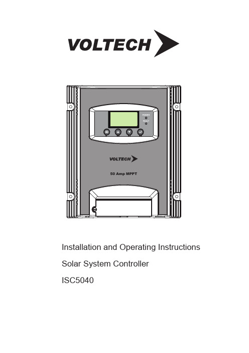
POWERFAULT50 Amp MPPTInstallation and Operating Instructions Solar System ControllerISC5040ABOUT THIS MANUALThese operating instructions come with the product and should be kept with it as a reference to all user’s of the product.Read these operating instructions carefully before use,Keep them over the entire life of the product,And pass then on to any future owner or user of this product.This manual describes the installation, function, operation and maintenance of the solar system controller ISC5040.These operating instructions are intended for end customers. A technical expert must be consulted in cases of uncertainty.SAFETY1. The solar controller may only be used in PV systems for charging Lead-Acid type batteries. This includes: SLA, VRLA, Lead-Calcium, AGM and GEL.Note; User’s should always refer to battery manufacturer/supplier’s recommended values for battery charging settings and float voltage setting.2. No energy source other than a solar panel (PV) may be connected to the solar charge controller.3. Do not connect any defective or damaged measuring equipment.4. Follow the general and national safety and accident prevention regulation.5. Never alter or remove the factory plates and identification labels.6. Keep children away from PV & Battery systems.7. Never open the device. (No user serviceable parts inside)8. One set solar module can connect with one controller only.9. Never touch bare cables.OTHER RISKSDanger of fire and explosionDo not use the solar charge controller in dusty environments, in the vicinity of solvents orwhere inflammable gases and vapors can occur.No open fires, flames or sparks in the vicinity of the batteries.Ensure that the room is adequately ventilated.Check the charging process regularly.Follow the charging instructions of the battery manufacturer.Battery acidAcid splashes on skin or clothing should be immediately treated with soap suds and rinsedwith plenty of water.If acid splashes into the eyes, immediately rinse with plenty of water. Seek medical adviceFault behaviorOperating the solar charge controller is dangerous in the following situations:The solar charge controller does not appear to function at all.The solar charge controller or connected cables are visibly damaged.Emission of smoke or fluid penetration.When parts are loose.If any of these occur, immediately disconnect the solar charge controller from the solar panels and battery.FunctionThis solar system controller is designed toMonitor the state of charge of the battery;Controls the charging process,Make sure Solar system works at proper condition.Charging Voltage is user programmable.OPERATING THE CONTROLLERThe display shows a variety of system data by symbols and digits. Both buttons control all settings and display windows.1. Display and operation elements.POWERFAULT 50 Amp MPPT LCD display for controller information and messages. Power LEDFail LEDConfirmation button in program Mode (Enter button)Pagedown buttonPageup buttonMenu button for switching display And enter setting mode.2. Display window. Change the display windows with the “Menu” button; (e.g. for 12V battery) 1. The default window will show like below, battery voltage/capacity volume of the battery.2. Press “menu” button once to check charging current.1. Charging Voltage Check & Program Press “menu” button 3 times. Window will switch to show BULK voltage setting. To change this setting; Press “enter” button once, you can program charge voltage via Pageup/Pagedown button: 12V Battery(14.0V-14.8V);24V Battery(28.0V-29.5V);36V Battery(42.0V-44.3V);48V Battery(56.0V-59.0V) Press “enter” or “menu” button to save setting.2. Press “menu” button 4 times. Window will switch to show FLOAT voltage setting. To change this setting; Press “enter” button once; you can program Float voltage via Pageup/Pagedown button: 12V Battery(13.0V-13.8V);24V Battery(26.0V-27.5V);36V Battery(39.0V-41.3V);48V Battery(52.0V-55.0V)Press “enter” or “menu” button to save setting.3.How to set up BULK/FLOAT voltage and DC load output function.3. Note :When the "Sensor Temp" port is inserted into the temperature sensor,Float voltage will vary accordingly to the ambient temperatures stated below:12V system: ≤0℃(14.1V), 0℃ - 20℃ (13.8V), ≥20℃ (13.5V);24V system: ≤0℃(28.2V), 0℃ - 20℃ (27.6V), ≥20℃ (27.0V);36V system: ≤0℃(42.3V), 0℃ - 20℃ (41.4V), ≥20℃ (40.5V);48V system: ≤0℃(56.4V), 0℃ - 20℃ (55.2V), ≥20℃ (54.0V);FEATURES1. Use with 12V/24V/36V/48V battery bank, the controller will detect voltage of battery automatically. With 3 charging stage: MPPT,constant voltage charging, and float charging, they are automatically performed.2. MPPT function - Implementing the latest MPPT technology the controller is able to harness the panels maximum available output at all times.3. Temperature CompensationISC5040 has an internal ambient temperature sensor that compensates during the float mode. INSTALLATION Install the controller in a ventilated area away from flammable materials and gases.The surface should be solid, even, dry and nonflammable.The battery to controller cable should be as short as possible (1-2mtrs is ideal) and be of a suitable diameter to minimize voltage loss.Do not assemble outdoor, the unit should be installed in the way to be protected against humidity, dripping, rainwater as well as direct and indirect heat (sunlight).To ensure the air circulation for cooling an area of 15cm on each side of the unit must be kept free.The LCD display should be protected against UV rays (e.g. sunlight). Long time exposure to UV rays can permanently discolor the LCD.The solar charge controller may only be connected to the local loads and the battery by trained personnel and in accordance with any applicable regulations.Follow the installation and operating instructions for all components of the PV system.Ensure that no cables are damaged.Ensure that polarity of Solar panel/battery/load is correct and use only insulated tools. WARNINGISC5040 can work with input voltage up to 95 Vdc maximum; when installing at this voltage, particularly with regard to module open circuit voltage (Voc), the entire solar energy system must be installed with protection class II. Cover solar modules during installation and use only insulated tools. 4. When the unit is in the default display mode, Pressing the “enter”button will turn the load ON or OFF manually.The arrow/lamp symbol will be displayed when the load terminal is ON.4. DC Load Output12/24/36/48V Max Output Current 50 A.DC load external power supply or battery is prohibited.CONNECTING / DIS-CONECTING SYSTEM SEQUENCEConnect the wires in the sequence from 1 to 6 according the above diagram; when Disconnect the wires in the REVERSE sequence from 6 to 1 according the above diagram.Use with 12V/24V/36V/48V battery bank, (controller will detect voltage of battery automatically).Never exceed the nominal ratings (see below technical data for reference).Suggested cable length, 10m solar panel connection cable/2m battery connection cable.Note : solar input is disconnecting and then reconnection, It need more than 5 seconds.1. Attention when connection:A: you need confirm the battery if it is 12V/24V36V/48V, the unit just can use 12V/24V36V/48V Lead-Acid battery and can’t for other specifications of the battery now.B: Solar panels open circuit voltage (VOC): the system of 12V battery for 16-95VDC solar panelthe system of 24V battery for 32-95VDC solar panelthe system of 36V battery for 48-95VDC solar panelthe system of 48V battery for 64-95VDC solar panel2.how to choose each connection cable:A: The requirements of PV panel to controller cable: PV1-F cable, PV TUV 2PFG 1169 length less than 8 meters, diameter 8-10 B: The requirements of battery to controller cable:UL1015 or same specification. Pure copper cable, length of 8AWG cable is 1.45 meters or length of 10AWG cable is 0.9 meter. Length tolerance of cable allowed only 5 mm. otherwise there will be big effect to charging voltage. ③④①②⑤⑥Max.650W PV array for 12V batteryMax.1300W PV array for 24V/36V/48V batteryTECHNICAL INFORMATIONCHARGING CURVEBulk: This is the first stage (MPPT) where the battery is in a low charge state. During this stage the controller delivers all of the available solar power to the Battery system.Absorption: In this stage (Constant Voltage) the controller charges at a constant voltage as the amount of current required to charge the battery is decreasing. The constant voltage regulation prevents overheating and excessive battery out-gassing; this stage will end when the battery charge current reduces to below 4 Amps OR after 4 hours of entering absorption mode.Float (Maintenance): After the battery is fully charged, the controller reduces to a lower Constant Voltage setting to maintain the Battery (also called trickle charge).PROTECTION FUNCTIONSOvercharge protectionBattery under-voltage protectionSolar panel reverse current protectionThe following installation faults do not destroy the controller. After correcting the fault, the device willcontinue to operate correctly:Overcharge protectionReverse polarity protection of panel and batteryAutomatic electronic fuseOpen circuit protection without batteryReverse current protection at nightW 056y r e t t a B V 21@ )x a m P (r e w o P y a r r A V P .x a M W 0031y r e t t a B V 84/63/42@ )x a m P (r e w o P y a r r A V P .x a M C D V 59)C O V ( e g a t l o V y a r r A V P .x a M C D V 67-61 e g n a R e g a t l o V T P P M y a r r A V P C D V 59-61y r e t t a B V 21@ e g n a R e g a t l o V t i u c r i c n e p o y a r r A V P C D V 59-23y r e t t a B V 42@ e g n a R e g a t l o V t i u c r i c n e p o y a r r A V P C D V 59-84y r e t t a B V 63@@ e g n a R e g a t l o V t i u c r i c n e p o y a r r A V P C D V 59-46yr e t t a B V 84 e g n a R e g a t l o V t i u c r i c n e p o y a r r A V P PV Input %99≥y c n e i c i f f e T P P M C D V 84/V 63/V 42/V 21e g a t l o V d e t a R y r e t t a B C D A 05t n e r r u C g n i g r a h C y r e t t a B V 21 C D A 05t n e r r u C g n i g r a h C y r e t t a B V 42 C D A 53t n e r r u C g n i g r a h C y r e t t a B V 63 C D A 52t n e r r u C g n i g r a h C y r e t t a B V 84Adjustable Charge Voltage(Bulk)14. 0-14. 8V/28. 0-29. 5V/42. 0-44. 3V/56. 0-59. 0V Output Adjustable Charge Voltage(Float)13. 0-13. 8V/26. 0-27. 5V/39. 0-41. 3V/52. 0-55. 0V A m 06t n e r r u c y b d n a t s t h g i N .x a MC °05+/C °01- e g n a R e r u t a r e p m e T g n i t a r e p O Max. Load Current DC Load output voltage Battery Voltage Over Discharge Voltage11.3/22.6/34.2/45.650A DCLoadOutputMAINTANANCEThe controller is maintenance-free. We strong suggest that all components of the PV system must be checked at least annually,Ensure adequate ventilation of the cooling elementCheck the cable strain reliefCheck that all cable connections are secureTighten screws if necessaryTerminal corrosion ERROR MESSAGESCaution! Please do not open the controller or attempt to replace components when troubleshooting. Improper maintenance can be hazardous to the user and the system.If the controller detects errors or unauthorized operating states, it shows error codes on the display. Error codes can generally be differentiated, whether there is a temporary malfunction, e.g. regulator overload or a more serious system error that can be remedied by appropriate external measures.Since not all errors can be simultaneously displayed, the error with the highest error number (priority) is displayed. If several errors are present, the second error code is displayed after remedying the more significant error.The Remark: When PV connected into the system, while battery disconnected, E1 and E2 may occur. This is normal. following meaning is assigned to the different error codes:1.Meaning: Battery reverse polarity warning, Red LED is shining.Remedy: Reconnect battery correctly. 2. 3.4. Meaning: Battery Voltage (Too high or too low), Red LED is shining.Remedy: Check battery voltage it might be too low or too high, possible recharge battery manually. If battery can’t be recharged, Replace battery & re-check.Meaning: Temperature is too high for the unit.Red LED is shiningRemedy:Stop charging for a while to cool down the unit.Meaning: Over current at the load output.Red LED is shining。
JD-200系列微机保护装置使用说明书

-3-
陕西金电电子科技有限责任公司
JD-200 系列微机保护装置使用说明书
1.概述
JL5005微机继电保护测试仪用户使用说明建议在使用JL系列继保测试系统之前请阅览本机使用说明书!

JL5005微机继电保护测试仪用户使用说明建议:在使用JL系列继保测试系统之前请阅览本机使用说明书!JL5005微机继电保护测试仪扬州金力电气有限公司目录第一章装置特点与技术参数 (1)第一节主要特点 (1)第二节技术参数 (2)第二章装置硬件结构 (6)第一节装置硬件组成 (6)第二节装置面板说明 (9)第三章快速入门 (12)第一节试验注意事项 (12)第二节开/关机步骤 (13)第三节键盘、鼠标操作使用方法 (14)第四节继电保护试验项目索引 (15)第四章软件操作方法 (18)第一节软件安装及驱动安装 (18)第二节交流试验 (21)第三节直流试验 (26)第四节频率试验 (28)第五节同期试验 (29)第六节电流电压试验 (32)第七节差动继电器 (33)第八节反时限过流继电器 (34)第九节中间继电器 (35)第十节功率方向 (36)第十一节阻抗阶梯 (38)第十二节零序保护 (41)第十三节整组试验 (43)第十四节状态系列 (47)第十五节阻抗相位特性 (49)第十六节精工电流 (50)第十七节差动试验 (51)第十八节谐波试验 (60)第十九节工频变化量 (61)第二十节故障再现 (62)第二十一节系统振荡 (63)第二十二节计量仪表 (65)第二十三节备自投试验 (66)新手指南附录A 驱动安装说明 (73)附录B USB通信常见故障排除 (75)第一章装置特点与技术参数第一节主要特点1、满足现场所有试验要求。
JL5005型具有标准的六相电流,六相电压同时输出,电流30A/相,电压125V/相。
六相并联电流可达180A。
既可对传统的各种继电器及保护装置进行试验,也可对现代各种微机保护进行各种试验,特别是对变压器差功保护和备自投装置,试验更加方便和完美。
2、各种技术指标完全达到电力部颁发的DL/T624-1997《继电保护微机型试验装置技术条件》的标准。
3、单机独立运行,内置高性能工控机,主频300--600MHz,内存128M,硬盘6--12G,运行Windows XP操作系统。
PSRC900D系列保护测控装置说明书

8 PSRC940D 备用电源自投装置 .................................. 38
8.1 基本配置及规格 ..............................................................................38 8.2 保护原理..........................................................................................39 8.3 定值设置..........................................................................................40 8.4 背板端子图 ......................................................................................41 8.5 典型接线原理图 ..............................................................................42 8.6 保护逻辑框图 ..................................................................................43
9 PSRC950D 配变保护测控装置 ..................... 基本配置及规格 ..............................................................................45 9.2 保护原理..........................................................................................46 9.3 定值设置..........................................................................................47 9.4 装置背板端子图 ..............................................................................49 9.5 典型接线原理图 ..............................................................................50 9.6 保护逻辑框图 ..................................................................................52
RCS-943TM型高压输电线路成套保护装置技术和使用说明书

RCS-943TM 型 高压输电线路成套保护装置
技术和使用司标准图标合成,确保资料名称、资料编号及其相对位置与本封面一致。
南瑞继保电气有限公司版权所有 本说明书适用于程序版本:RCS-943TM V2.10 本说明书和产品今后可能会有小的改动,请注意核对实际产品与说明书的版本是否相 符。 更多产品信息,请访问互联网:http://www.nari-relays.com
2.3.1 整组动作时间 ........................................................................................................................................................2 2.3.2 起动元件.................................................................................................................................................................2 2.3.3 距离保护.................................................................................................................................................................2 2.3.4 零序过流保护 ........................................................................................................................................................3 2.3.5 过负荷告警 ............................................................................................................................................................3 2.3.6 暂态超越.................................................................................................................................................................3 2.3.7 测距部分.................................................................................................................................................................3 2.3.8 自动重合闸 ............................................................................................................................................................3 2.3.9 电磁兼容.................................................................................................................................................................3 2.3.10 绝缘试验...............................................................................................................................................................3 2.3.11 输出接点容量......................................................................................................................................................3 2.3.12 通信接口...............................................................................................................................................................4 2.3.13 光纤接口...............................................................................................................................................................4
保护参考整定计算说明
保护参考整定计算说明注意:本说明仅供参考,所有电流、电压元件定值非特别说明均为二次值!1.MMP-5012D 电动机保护测控装置整定参考● 额定电流整定:按电动机额定电流整定:nLHIe =In ● 启动速断定值:按电动机最大启动电流整定: nLH KknqIe =Idzj KK :取1.5;Nq :为电动机启动倍数取4~7;Ie :为电动机额定电流。
● 运行速断定值:同启动速断定值整定,可靠系数Kk 取0.8。
● 启动时间:根据电动机带的负荷性质决定电动机启动时间长短,以实际为准,据运行经验提供参数:水泵启动时间为4~5s ;空压机启动时间为4~5s ;抽风机启动时间为10~16s :轧机启动时间为10s 左右。
● 过流保护定值:按电动机额定电流1.8倍整定,nLHKkIe =Idzj Kk 取1.8;Ie 电动机的额定电流。
● 过流时间定值:定时限时间定值一般取0.5s ,反时限时间一般取4~16s 。
● 正序过流定值:按电动机额定电流的1.2倍整定:nLH KkIe =Idzj Kk 取1.2;Ie 电动机的额定电流。
● 正序时间整定:一般取1s 。
● 负序过流定值:按电动机额定电流的0.25倍整定。
nLHKkIe =Idzj Kk 取0.25倍,Ie 电动机的额定电流。
●负序时间定值:一般整定为1s 。
●零序过流定值:按电动机的接地电容电流的1.5倍整定,一般整定Ic0≥5A 。
●零序过流时间定值:一般整定为0.5~1s 跳闸。
●过电压定值:按电动机的额定电压1.3倍整定。
●过电压时间整定:一般整定30s 。
● 低电压保护定值:对于不重要的电动机,电源有备自投时不允许自启动的电动机,电压定值一般按额定电压的60~70%,延时为0.5s 作用跳闸。
对于重要的电动机又要保证自启动时,电压定值按额定电压的0.45~0.55%,延时为6~10s 作用于跳闸。
对于根据安全需要保证电动机切除时间长且失压后又不允许自启动的则电压定值按额定电压的0.25~0.4倍整定,时间定值一般整定6~10s 。
保护装置说明书

篇一:保护装置说明书产品使用前请仔细阅读本说明书wtgb2000微机综合保护装置说明书使用说明书安装使用前请详细阅读本使用说明书淮南万泰荣博照明科技有限公司出版日期2014-01-11警告小心注意!通电前注意事项 ? 核对装置箱体上的出厂标签与出厂检验报告,并确认与定货一致。
? 检查装置外壳是否有明显的损伤和变形。
? 检查各插件插拔接触是否可靠。
? 装置外壳是否可靠接地。
? 装置供电电源为交流或直流220v。
? 检查输入装置的交流量各相序及极性应正确无误。
1一、概述wtgb2000微机综合保护装置(以下简称产品)是功能先进的微机型综合保护装置,主要应用于10kv及以下电压等级的高压开关柜保护中,可对进线、电容器、电动机、厂用变等设备进行保护。
1.1 保护功能配置见表1。
产品根据保护对象的不同,设有四种保护模式(可在“设置”菜单的“保护对象”一栏设定),分别适用于线路、电容器、电动机、厂变不同保护对象。
序号功能名称线路电容器电动机厂用变1 两段式电流保护√√√√2 过流反时限保护√√3 负序电流保护√4 过负荷保护√√√5 三相一次重合闸√6 后加速保护√7 过电压保护√√8 低电压保护√√√√9 零序电流保护√√√√10 零序反时限保护√11 不平衡电流保护√12 低频减载√13 启动时间过长√14 过热保护√15 控制回路异常告警√√√√16 弹簧未储能告警√√√√17 tv断线检测√√√√18 非电量保护ⅰ√19 非电量保护ⅱ√20 非电量保护ⅲ√21 重瓦斯保护√22 高温保护√23 遥信、遥控功能√√√√24 遥测√√√√表11.2 产品主要特点2a. 本产品为微机保护装置,其元器件采用工业品,稳定性、可靠性高,可以在高压开关柜等恶劣的环境中工作;宽范围使用环境温度-25℃~+55℃。
b. 单台装置通过菜单设置,轻松实现对馈线、电容器、电动机、厂用变等设备的保护,降低装置和备件储备成本。
PCS-9611D_X_说明书_国内中文_国内标准版_X_R2.13

危险! 意味着如果安全预防措施被忽视,则会导致人员死亡,严重的人身伤害,或 严重的设备损坏。
警告! 意味着如果安全预防措施被忽视,则可能导致人员死亡,严重的人身伤害, 或严重的设备损坏。
警示! 意味着如果安全预防措施被忽视,则可能导致轻微的人身伤害或设备损坏。 本条特别适用于对装置的损坏及可能对被保护设备的损坏。
特别注意,一些通用的工作于高压带电设备的工作规则必须遵守。如果不遵守可能导致严重的 人身伤亡或设备损坏。
危险!
在一次系统带电运行时,绝对不允许将与装置连接的电流互感器二次开路。该回路开路可能会 产生极端危险的高压。
南京南
警告!
曝露端子 在装置带电时不要触碰曝露的端子等,因为可能会产生危险的高电压。
我们对本文档及其中的内容具有全部的知识产权。除非特别授权,禁止复制或向第三方分发。凡侵犯本公司版权等知识产权的,本公司必 依法追究其法律责任。 我们定期仔细检查本文档中的内容,在后续版本中会有必要的修正。但不可避免会有一些错误之处,欢迎提出改进的意见。 我们保留在不事先通知的情况下进行技术改进的权利。
南京南瑞继保电气有限公司
技术支持,请联系: 电话:025-52107703、8008289967、4008289967 传真:025-52100770 或登陆网站:/ser_sup
公司总部:南京市江宁区苏源大道 69 号,邮编 211102 生产地址:南京市江宁区新丰路 18 号,邮编 211111 公司网址:
警告!
为增强或修改现有功能,装置的软硬件均可能升级,请确认此版本使用手册和您购买的产品相 兼容。
警告!
电气设备在运行时,这些装置的某些部件可能带有高压。不正确的操作可能导致严重的人身伤 害或设备损坏。
DCAP-5080D发电机监控保护装置使用说明书
湖南紫光测控有限公司 2007-2-10
DCAP-5080D 发电机监控保护装置使用说明书
目
录Leabharlann 1 装置概述 ....................................................................................................................................... 3 2 主要功能 ....................................................................................................................................... 3 3 使用说明 ....................................................................................................................................... 3 3.1 交流电压输入回路 ........................................................................................................... 3 3.2 交流电流输入回路 ........................................................................................................... 4 3.3 直流电源输入回路 .........................................
5012D保护装置说明

MMP-5012D电动机综合保护测控装置MMP-5012D电动机综合保护测控装置适用于35KV以下电压等级的中高压异步电动机作为后备保护。
1.主要功能●保护功能启动速断保护速断保护两段过流保护(定时限)反时限过流保护(一般、非常、极端)负序过电流保护零序过电流保护过负荷保护过热保护低电压保护过电压保护非电量保护●告警功能CT断线告警PT断线告警控制回路断线告警装置故障告警●测控功能遥信:14路开入量遥测:电流、电压、频率、功率、功率因数、电度量、一次值、二次值均可独立显示。
遥控:对断路器进行装置本身及远方分、合闸操作。
开出:两路跳闸输出、一路合闸输出、两路可编程信号输出、一路掉电输出。
通讯功能:采用国际标准RS485通讯接口,标准Modbus通信规约。
谐波分析:可显示15次谐波分析。
,●保护辅助功能联跳(具有现场可编逻辑功能,可灵活用于各种工艺联锁)2.保护逻辑框图IA>Izd3IB>Izd3IC>Izd3I0>I0zdUbc<Udyzd Uca<UdyzdUfx>8V Uzx<30VIA≥0.5A IB≥0.5A IC≥0.5A 过流Ⅰ段过流Ⅱ段过流Ⅲ段/反时限零序过流低电压保护PT断线CT断线控制回路异常遥控操作I2>I2zd负序过流/反时限IA>Izd1IB>Izd1IC>Izd1IA>Izd2IB>Izd2IC>Izd2启动速断IA>Izd0IB>Izd0IC>Izd0HW=1Ubc>Ugyzd Uca>Ugyzd过电压保护K1I1 +K2I2热复归过热保护2KR1KR2非电量1非电量2KR3KR4非电量3非电量4启动PSRC962D逻辑框图过负荷3.定值整定●电动机保护测控装置参数整定●电动机保护测控装置定值整定4.通讯信息表装置遥测信息表5.装置背端子图及原理图MMP-5012D装置背后接线端子及说明MP-5012D电动机综合保护测控装置典型二次接线图。
5080D保护装置说明
MMP-5080D微机电压监测及并列装置
MMP-5080D微机电压监测及并列装置适用于35KV以下电压等级的母线及PT的保护,集保护、测量和母线电压并列切换于一体。
其主要功能如下:
1.主要功能
●保护功能
过压保护
低压保护
零序过压保护
●并列功能
手动并列
自动并列
断电自保持
●告警功能
两段母线PT断线告警
装置故障告警
●测控功能
遥信:14路开入量
遥测:线电压、相电压、一次值、二次值均可独立显示。
通讯功能:采用国际标准RS485通讯接口,标准Modbus通信规约。
谐波分析:可显示15次谐波分析。
,
2.保护逻辑框图
UL1>ULzd
Ⅰ母零序过压遥控操作
Uab1<Udyzd Ubc1<Udyzd Uca1<Udyzd Ufx1>8V Uzx1<30V Ⅰ母低电压保护
Ⅰ母PT断线
Ⅰ母过电压保护UL2>ULzd Ⅱ母零序过压
Ⅱ母过电压保护Uab2<Udyzd Ubc2<Udyzd Uca2<Udyzd Ufx2>8V Uzx2<30V Ⅱ母低电压保护
Ⅱ母PT断线
PSRC982D逻辑框图
3.定值设置
●
●
●电压综合保护兼并列装置遥测信息表
●电压综合保护兼并列装置遥信信息表
5.装置背端子图及原理图
MMP-5080D微机电压监测及并列装置背后接线端子及说明
MMP-5080D微机电压监测及并列装置典型设计。
Eaton EHD3015 电路保护设备说明书

Eaton EHD3015Eaton Series C complete molded case circuit breaker, F-frame, EHD, Complete breaker, Fixed thermal, Fixed magnetic trip type, Three-pole, 15 A, Load side, 50/60 HzGeneral specificationsEaton Series C complete molded case circuit breakerEHD30157866793170443.38 in 6 in4.13 in 4.15 lb Eaton Selling Policy 25-000, one (1) year from the date of installation of the Product or eighteen (18) months from the date of shipment of the Product, whichever occurs first.UL Listed Product NameCatalog Number UPCProduct Length/Depth Product Height Product Width Product Weight WarrantyCertificationsEaton Corporation plc Eaton House30 Pembroke Road Dublin 4, Ireland © 2023 Eaton. Todos los derechos reservados. Eaton is a registered trademark.All other trademarks areproperty of their respective owners./socialmediaSeries C 18 kAIC at 240 Vac 14 kAIC at 480 Vac FEHD50/60 HzComplete breaker Load side 15 A Fixed thermal, fixed magnetic Three-poleEaton's Volume 4—Circuit Protection Types EHD and FDB 10 Amperes AB DE-ION Circuit Breakers EHD3 2D PDF EHD3 3D Inventor EHD3 2D Drawing Xchange EHD3 3D Model XchangeF-frame Molded Case Circuit Breaker DrawingTime Current Curves for Series C® F-Frame Circuit Breakers MOEM MCCB Product Selection Guide Counterfeit and Gray Market Awareness Guide Breaker service centersF-Frame 310+ Molded-case circuit breakers 15-225A Installation Instructions for EHD, EDB, EDS, ED, EDH, EDC, FDB, FD, HFD, FDC, HFDDC Circuit Breakers and Molded Case SwitchesSeries Interrupt rating Frame Circuit breaker type Frequency rating Circuit breaker frame type Terminals Amperage Rating Trip TypeNumber of poles CatálogosCurvas de corriente de tiempoDibujos FolletosGuías de especificaciones de productoInstrucciones de instalación。
- 1、下载文档前请自行甄别文档内容的完整性,平台不提供额外的编辑、内容补充、找答案等附加服务。
- 2、"仅部分预览"的文档,不可在线预览部分如存在完整性等问题,可反馈申请退款(可完整预览的文档不适用该条件!)。
- 3、如文档侵犯您的权益,请联系客服反馈,我们会尽快为您处理(人工客服工作时间:9:00-18:30)。
MMP-5040D电容器保护测控装置
MMP-5040D电容器保护测控装置适用于35KV以下电压等级的非直接接地或小电阻接地系统中,作为并联补偿电容器保护之用。
其主要功能如下:
1.主要功能
●保护功能
速断保护
两段过流保护(定时限)
反时限过流保护(一般、非常、极端)
低电压保护
过电压保护
零序过电流保护
●告警功能
CT断线告警
PT断线告警
控制回异常告警
装置故障告警
●测控功能
遥信:14路开入量
遥测:电流、电压、频率、功率、功率因数、电度量、一次值、二次值均可独立显示。
遥控:对断路器进行装置本身及远方分、合闸操作。
开出:两路跳闸输出、一路合闸输出、两路可编程信号输出、一路掉电输出。
通讯功能:采用国际标准RS485通讯接口,标准Modbus通信规约。
谐波分析:可显示15次谐波分析。
●保护辅助功能
联跳(具有现场可编逻辑功能,可灵活用于各种工艺联锁)
2.保护逻辑框图
零序过流
CT断线
控制回路异常
遥控操作
低电压保护
PT断线
过电压保护
PSRC920D逻辑框图
复压闭锁过流Ⅰ段
复压闭锁过流Ⅱ段过流Ⅲ段/反时限
3.定值设置
●电容器保护测控装置参数整定
注意:装置参数同定值一样重要,请务必按照实际情况整定。
●电容器保护测控装置定值整定
●电容器保护测控装置遥测信息表
●
5.装置背端子图及原理图
MMP-5040D电容器保护测控装置背后接线端子及说明
MMP-5040D电容器保护测控装置典型二次接线图。
