Appendix A KMS Client Setup Keys
系统管理员版本6.3 Manager(Windows版)复制设置指南(ExpressCluster
SystemManager Version 6.3 Manager (Windows Version) Duplication Setup Guide (ExpressCluster X Edition)June 2016CONTENTSChapter 1Preface (3)Chapter 2Configuration Procedure (4)2.1Setting up ExpressCluster X (4)2.2Setting up MasterScope SystemManager (10)2.3Set up the start setting of MasterScope SystemManager (12)Chapter 3Uninstalling SystemManager (16)3.1Uninstalling SystemManager (16)3.2Deleting Files (16)Chapter 4Other Notes (16)4.1Registering Licenses (16)DisclaimerThe contents of this document are subject to change without notice.NEC Corporation takes no responsibility for any technical or editorial errors, or omissions, in this document.In addition, you are responsible for installing and using the software in accordance with the descriptions in this document in order to obtain the expected results.NEC Corporation owns the copyright to the contents of this document. You are not permitted to reproduce, modify, or translate this document in whole or in part without the permission of NEC Corporation.Trademark informationCLUSTERPRO® X is a registered trademark of NEC Corporation.Microsoft and Windows are registered trademarks of Microsoft Corporation in the United States and other countries.Other product names and slogans in this document are trademarks or registered trademarks of their respective companies.Other system names, company names, and product names are trademarks or registered trademarks of their respective companies.Chapter 1 PrefaceThis document provides an example procedure for using ExpressCluster X to set up a cluster configuration that has two nodes (for duplication). ExpressCluster X is an NEC product that can be used to switch running processes between nodes in a duplicated system.In this document, a host system included in a cluster is referred to as a node.Supplemental informationUpgrading an OSIf the incorrect procedure is used to upgrade the OS on a cluster server, failovers might occur at unexpected times. In the worst case, this might damage the system.Only upgrade the OS in accordance with the procedure on the setup card.This also applies when applying a service pack.Application rangeThis document describes ExpressCluster X 1.0 for Windows.ExpressCluster X® is a registered trademark of NEC Corporation.Microsoft® and Windows®are either registered trademarks or trademarks of Microsoft Corporation in the United States and/or other countries.Other system names, company names, and product names are trademarks or registered trademarks of their respective companies.Chapter 2 Configuration ProcedureThis chapter provides a procedure for configuring a MasterScope SystemManager cluster environment.2.1 Setting up ExpressCluster XThis document assumes that ExpressCluster X is installed and that a cluster environment has been set up. For details about how to configure a cluster environment, also see the ExpressCluster X documents.* These documents can be downloaded from the following website: /en/global/prod/expresscluster/en/support/manuals.html?Creating failover groupsFor ExpressCluster X, nodes connected to the cluster are managed using units called failover groups (referred to as groups below).For details about how to create groups, see the relevant ExpressCluster X document (chapter 5 in the Installation and Creation Guide).Figure 2-1 WebManagerSetting up shared resourcesThe following describes how to set up shared resources for a failover group.Here, the following shared resources are assumed:⏹Floating IP address: 192.168.1.10⏹Shared (mirror) disk: Y drive⏹Service:Manager: MasterScope UMF Operations Manager_n (The italicized n representsa number.)Start Builder, and then select a failover group. (Here, select [MasterScope].)Figure 2-2 Group PropertiesRight click the group, and then select [Add Resource] from the displayed pop-up menu. The [Definition of a resouce] dialog box is displayed.First, set up the shared disk. For [Type], select [disk resource] or [mirror disk resource], and then enter the group name of the shared disk in the [Name] text box. Set up the disk in accordance with the instructions in the dialog box.Figure 2-3 Definition of a resouce (Shared Disk)Next, set up the floating IP address. Right click the group, select [Add Resource] from the displayed pop-up menu, select [floating ip resource] for [Type], and then enter the group name in the [Name] text box.Figure 2-4 Definition of a resouce (Floating IP Address)Specify the floating IP address in the [IP Address] text box.Figure 2-5 Floating IP Address AdditionSwitching between connected nodesTo switch between the active and standby nodes, use the following method.Open a command prompt, and then enter the following command:* A direct command can be entered because the environment variable PATH isregistered when ExpressCluster X is installed.The nodes can also be switched by right clicking the icon next to a group namedisplayed in the left WebManager pane and then selecting [Move] from the displayedpop-up menu.Figure 2-6 Switching Between Connected Nodes2.2 Setting up MasterScope SystemManagerInstall the MasterScope SystemManager manager on the Windows computers to be used as active and standby servers.For details about how to do so, see the Release Notes supplied with the product.As described in 2.1 Setting up ExpressCluster X, the following shared resources are assumed:∙Virtual host name: vhost1∙Shared disk: Y driveNotes* Install MasterScope SystemManager on the active server first, and then on the standby server.* It must be possible to reference the shared disk when installing the active server manager.* Use the same drive and folder as the installation destination for MasterScope SystemManager on the active and standby servers.* vhost1 is a host name that can be resolved to a floating IP address (192.168.1.10).The following describes the procedure for installing the MasterScope SystemManager manager.First, start up the cluster from the active node, and then install MasterScope SystemManager on the active node.In the installation settings window, specify the following settings:\Manager\sg is automatically added to the data area folder, and settings that must be shared are stored here.After installation finishes, confirm that \Manager\sg has been created in the data area folder.Next, set up the MasterScope SystemManager manager on the standby node.In the installation settings window, specify the following settings:After installation finishes, change the service startup attributes on both the active and standby nodes.In the [Start] menu, click [Administrative Tools] and then [Services]. Next, stop the [MasterScope UMF Operations Manager_1] service, and then change the [Startup type] in the properties from [Automatic] to [Manual].Figure 2-7 Service Properties* If using the bundled DB, change the [Startup type] for the bundled DB service to [Manual] in the same way.2.3 Set up the start setting of MasterScope SystemManagerSet up the service. Right click the group, select [Add Resource] from the displayed pop-up menu, select [execute resource] for [Type], and then enter the group name in the [Name] text box.Figure 2-8 Definition of a resouce (Service)Specify the Windows service name for the product in the [Service Name] text box.Figure 2-9 Service Name SpecificationThe service name varies depending on the node, so enter the following service name.* serial-number represents a number. Check the actual value in the Windows [Administrative Tools].To set up the dependencies, clear the [Follow the default dependence] check box, and then add resources that depend on the floating IP address and shared disk.Figure 2-10 Dependency SpecificationAfter specifying the settings, return to the failover group properties, and then confirm that the settings have been applied (by confirming that the window is like the one shown in Figure 2-2).* If using the bundled DB, add the resource for the bundled DB service in the same way. Set up the resource dependencies so that the bundled DB is dependent on SystemManager.Service name is [fdb_wfdbn].n indicates a service number of 1 or higher.(The value is set during installation of MasterScope products.)This manual describes startup settings for failover groups.Separately set up service monitoring in accordance with the relevant ExpressCluster X document.This concludes the ExpressCluster X setup.Chapter 3 Uninstalling SystemManager3.1 Uninstalling SystemManagerTo uninstall SystemManager, perform the procedure described in the SystemManager Release Memo (relememo.pdf).3.2 Deleting FilesAfter uninstalling SystemManager, files and directories remain on the shared disk.Manually delete directories on the shared disk specified during installation.Chapter 4 Other Notes4.1 Registering LicensesRegister licenses for a cluster environment on both the active and standby nodes.。
Klocwork培训手册K9.1

4.2 命令行分析 ........................................................................................................................... 11 4.3 KMC 分析步骤.......................................................................................................................12 4.4 TORNADO 程序分析 .................................................................................................................14
戴尔无线键盘和鼠标快速入门指南说明书

Set up the keyboard and mouse设置键盘和鼠标設定鍵盤和滑鼠Memasang keyboard dan mouseキーボードとマウスをセットアップする14Finish Windows setup完成 Windows 设置 | 完成 Windows 設定Selesaikan penataan Windows | Windows セットアップを終了するEnable security and updates启用安全和更新功能啟用安全性與更新Aktifkan pengamanan danpemutakhiranセキュリティとアップデートを有効にするSign in to your Microsoft account orcreate a local account登录 Microsoft 帐户或创建本地帐户登入您的 Microsoft 帳號或建立本機帳號Masuk ke dalam akun Microsoft Andaatau buat akun lokalMicrosoft アカウントにサインインする、またはローカルアカウントを作成するConnect to your network连接到网络連接網路Hubungkan ke jaringan Andaネットワークに接続するExplore resources浏览资源 | 探索資源Jelajahi sumber daya | リソースを検索するHelp and Tips帮助与提示 | 說明與秘訣Bantuan dan Tips | ヘルプとヒントMy Dell我的 Dell | 我的 DellDell Saya | マイデルRegister your computer注册计算机 | 註冊您的電腦Daftarkan komputer Anda | コンピュータを登録するSee the documentation that shipped with the wireless keyboardand mouse.请参阅无线键盘和鼠标随附的文档。
vistanita duplicate finder密钥 -回复
vistanita duplicate finder密钥-回复如何获取Vistanita Duplicate Finder的密钥。
第一步:了解Vistanita Duplicate FinderVistanita Duplicate Finder是一款功能强大的重复文件查找工具,可以帮助用户快速扫描计算机中的重复文件,并提供删除或移动这些文件的选项。
该软件简单易用,可以提高您电脑的整体性能,节省大量的存储空间。
第二步:下载Vistanita Duplicate Finder在您决定获取Vistanita Duplicate Finder的密钥之前,首先需要下载该软件。
您可以通过访问Vistanita Duplicate Finder的官方网站或其他可信的软件下载网站来下载安装程序。
第三步:安装Vistanita Duplicate Finder下载完成后,双击安装程序并按照提示进行安装。
这个过程通常很简单,只需点击“下一步”并接受许可协议即可完成安装。
第四步:运行Vistanita Duplicate Finder安装完成后,您可以在桌面或开始菜单中找到Vistanita Duplicate Finder的快捷方式。
双击该图标以运行该程序。
第五步:注册Vistanita Duplicate Finder当您首次运行Vistanita Duplicate Finder时,您将看到一个注册界面。
在这里,您需要输入注册信息以获取软件的完整功能和访问权限。
要获取Vistanita Duplicate Finder的密钥,您有几个选择:1. 购买正版密钥:访问Vistanita Duplicate Finder的官方网站,并按照购买流程购买正版密钥,以获取完整的使用权限和技术支持。
一旦您完成购买,您将收到一封含有密钥的电子邮件。
2. 使用试用版密钥:如果您不确定是否要购买Vistanita Duplicate Finder,也可以选择使用试用版密钥。
利用LabWindows CVI实时模块将台式计算机作为实时目标使用说明书
Using Desktop PCs as RT Targets with the LabWindows /CVI Real-Time Module The LabWindows/CVI Real-Time Module can execute applications on real-time (RT) targets running a real-time operating system, including a desktop PC converted to an RT system. This document describes the three methods you can use to configure a desktop PC as an RT target and contains information about installing software on the desktop PC.Note Refer to the Programmer Reference»Creating and Downloading DLLs to Real-Time Targets section of the LabWindows/CVI Help for more information about using LabWindows/CVI with RT targets.ContentsSystem Requirements (2)Configuring a Desktop PC Using a Utility USB Drive (2)Boot from the USB Drive (2)Format a Drive or Partition (3)Configuring a Desktop PC Using a Boot Disk (4)Configuring a Desktop PC Using a Format Disk (5)Installing Software (7)Resources (8)™™System RequirementsTo configure a desktop PC as an RT target, ensure that the PC meets thefollowing requirements:•Processor based on the x86 architecture.•Supported Ethernet chipset, the Ethernet device from the Real-TimeDeployment License Bundle for Standard PCs, or a supported Ethernetcard.•Formatted hard drive or boot partition on the desktop PC with theFAT32 file system.• 3.5 inch floppy drive or bootable USB port on the desktop PC.etspc for up-to-date information about supported hardware and the specific desktop PCspecifications that National Instruments recommends.Configuring a Desktop PC Using a Utility USB DriveYou can use a utility USB drive in the following ways:•Boot from the USB drive every time.•Use the USB drive to format the hard drive. After you format the harddrive, the RT target boots directly from the hard drive.Create a desktop PC utility USB drive using NI Measurement &Automation Explorer (MAX). Select Tools»RT Disk Utilities»CreateDesktop PC Utility USB Drive in MAX to create the utility USB drive. Boot from the USB DriveYou can use a utility USB drive to boot from the USB drive and launch theReal-Time Module software on the hard drive of the desktop PC. If there isno Real-Time Module software installed on the hard drive, the utility USBdrive boots the PC into safe mode, where you can install software.Complete the following steps to configure a desktop PC to boot using autility USB drive.1.If the desktop PC does not include a motherboard with a supportedEthernet chipset, install a supported Ethernet card or the Ethernetdevice included with the Real-Time Deployment License Bundle forStandard PCs in an available PCI slot of the PC.2.Connect a monitor and keyboard to the desktop PC to display andrespond to BIOS configuration utility prompts.Using Desktop PCs as RT © National Instruments Corporation 3Using Desktop PCs as RT TargetsNote National Instruments recommends that you remove from the desktop PC anyPCI boards not supported by the Real-Time Module to reduce the possibility of resource conflicts. For example, remove sound cards, SCSI adapters, and modems from the desktop PC.3.Turn on the desktop PC and access the BIOS configuration utility.Note BIOS configurations and configuration interfaces for desktop PCs vary among different manufacturers and system models. Consult the motherboard or system manual for information about accessing and configuring the BIOS settings of the desktop PC.4.Set the boot configuration to use a USB drive as the first boot device.5.Disable legacy USB support.6.Disable any unnecessary integrated peripherals that use an interruptrequest line (IRQ). For example, disable unused serial ports orintegrated sound on the desktop PC.7.Save the configuration changes and exit the BIOS configuration utility.8.Insert the utility USB drive into an empty USB port on the desktop PCand reboot the desktop PC.9.Select the Boot using software installed on the hard-disk optionfrom the utility USB drive menu. The desktop PC boots into thereal-time operating system or into safe mode. Refer to the InstallingSoftware section for information about installing the Real-TimeModule software on the hard drive if the PC boots into safe mode.Format a Drive or PartitionYou can use a utility USB drive to permanently install the Real-TimeModule software on the hard drive of the desktop PC. A format option ofthe utility USB drive resets a previously formatted and partitioned harddrive and installs files to the desktop PC to allow you to start the PC withouta boot disk or USB drive.Caution The format utility of the utility USB drive overwrites the hard drive boot sector and master boot record, erasing all pointers to data on the drive. If you have a dual-boot configuration, the changes to the master boot record remove the ability to boot into the secondary operating system.Complete the following steps to format the hard drive and configure adesktop PC using a utility USB drive.1.If the desktop PC does not include a motherboard with a supportedEthernet chipset, install a supported Ethernet card or the Ethernetdevice included with the Real-Time Deployment License Bundle forStandard PCsin an available PCI slot of the PC.Using Desktop PCs as RT Targets 2.Connect a monitor and keyboard to the desktop PC to display andrespond to BIOS configuration utility prompts.Note National Instruments recommends that you remove any PCI boards not supported by the Real-Time Module to reduce the possibility of resource conflicts. For example, remove sound cards, SCSI adapters, and modems from the desktop PC.3.Turn on the desktop PC and access the BIOS configuration utility.Note BIOS configurations and configuration interfaces for desktop PCs vary among different manufacturers and system models. Consult the motherboard or system manual for information about accessing and configuring the BIOS settings of the desktop PC.4.Set the boot configuration to use a USB drive as the first boot device. 5.Disable legacy USB support.6.Disable any unnecessary integrated peripherals that use an interruptrequest line (IRQ). For example, disable unused serial ports orintegrated sound on the desktop PC.7.Save the configuration changes and exit the BIOS configuration utility.8.Insert the utility USB drive into an empty USB port on the desktop PCand reboot the desktop PC.9.Select the Format hard disk option from the utility USB drive menuand follow the directions on the screen.10.Remove the utility USB drive and reboot the desktop PC to boot intothe real-time operating system. The desktop PC boots into safe modethe first time the system boots from the hard drive. Refer to theInstalling Software section for information about installing theReal-Time Module software on the hard drive if the PC boots intosafe mode.Configuring a Desktop PC Using a Boot DiskYou can use a boot disk to launch the Real-Time Module software that youinstall on the hard drive of a desktop PC. If there is no Real-Time Modulesoftware installed on the hard drive, the desktop PC boots into safe mode,where you can install software.Create a desktop PC boot disk using NI Measurement & AutomationExplorer (MAX). Select Tools»RT Disk Utilities»Create Desktop PCBoot Diskin MAX to create the desktop PC boot disk.© National Instruments Corporation 5Using Desktop PCs as RT TargetsComplete the following steps to configure a desktop PC using a boot disk.1.If the desktop PC does not include a motherboard with a supportedEthernet chipset, install a supported Ethernet card or the Ethernetdevice included with the Real-Time Deployment License Bundle forStandard PCs in an available PCI slot of the PC.2.Connect a monitor and keyboard to the desktop PC to display andrespond to BIOS configuration utility prompts.Note National Instruments recommends that you remove from the desktop PC anyPCI boards not supported by the Real-Time Module to reduce the possibility of resource conflicts. For example, remove sound cards, SCSI adapters, and modems from the desktop PC.3.Turn on the desktop PC and access the BIOS configuration utility.Note BIOS configurations and configuration interfaces for desktop PCs vary among different manufacturers and system models. Consult the motherboard or system manual for information about accessing and configuring the BIOS settings of the desktop PC.4.Set the boot configuration to use the floppy drive as the first boot device. 5.Disable legacy USB support. 6.Disable any unnecessary integrated peripherals that use an interruptrequest line (IRQ). For example, disable unused serial ports orintegrated sound on the desktop PC.7.Save the configuration changes and exit the BIOS configuration utility.8.Insert the desktop PC boot disk in the floppy drive and reboot thedesktop PC. The desktop PC boots into the real-time operating systemor into safe mode. Refer to the Installing Software section forinformation about installing the Real-Time Module software on the hard drive if the PC boots into safe mode.Configuring a Desktop PC Using a Format DiskYou can use a format disk to permanently install the Real-Time Modulesoftware on the hard drive of the desktop PC. A format disk resets apreviously formatted and partitioned hard drive and installs files to thedesktop PC to allow you to start the PC without a boot disk.Create a desktop PC format disk using NI Measurement & AutomationExplorer (MAX). Select Tools»RT Disk Utilities»Create Desktop PCFormat Hard Drive Diskin MAX to create the desktop PC format disk.Using Desktop PCs as RT Targets Caution A format disk overwrites the hard drive boot sector and master boot record, erasing all pointers to data on the drive. If you have a dual-boot configuration, the changes to the master boot record remove the ability to boot into the secondary operating system.Complete the following steps to configure a desktop PC using a formatdisk.1.If the desktop PC does not include a motherboard with a supportedEthernet chipset, install a supported Ethernet card or the Ethernetdevice included with the Real-Time Deployment License Bundle forStandard PCs in an available PCI slot of the PC.2.Connect a monitor and keyboard to the desktop PC to display andrespond to BIOS configuration utility and format prompts.Note National Instruments recommends that you remove from the desktop PC anyPCI boards not supported by the Real-Time Module to reduce the possibility of resource conflicts. For example, remove sound cards, SCSI adapters, and modems from the desktop PC.3.Turn on the desktop PC and access the BIOS configuration utility.Note BIOS configurations and configuration interfaces for desktop PCs vary among different manufacturers and system models. Consult the motherboard or system manual for information about accessing and configuring the BIOS settings of the desktop PC.4.Set the boot configuration to use the floppy drive as the first boot device. 5.Disable legacy USB support. 6.Disable any unnecessary integrated peripherals that use an interruptrequest line (IRQ). For example, disable unused serial ports orintegrated sound on the desktop PC.7.Save the configuration changes and exit the BIOS configuration utility.8.Insert the desktop PC format disk in the floppy drive and reboot the PC.9.Follow the directions that appear on the screen. 10.Remove the desktop PC format disk from the floppy drive and rebootthe desktop PC to boot into the real-time operating system. Thedesktop PC boots into safe mode the first time the system boots fromthe hard drive. Refer to the Installing Software section for informationabout installing the Real-Time Module software to the hard drive if thePC boots into safe mode.Installing SoftwareComplete the following steps to install software on the desktop PC.1.Boot the desktop PC into the real-time operating system. The desktopPC loads with the basic real-time operating system and a null IPaddress of 0.0.0.0.2.Open MAX on another computer in the same subnet and expand theRemote Systems category. MAX lists the desktop PC as 0.0.0.0 inthe Remote Systems category.3.Click on the 0.0.0.0 entry to access the Network Settings tab.4.Enter a name for the RT target in the Name text box.5.Set the network configuration options of the RT target in theIP Settings section and click the Apply button. Refer to theConfiguring Network Settings book, accessible by browsing toMAX Remote Systems Help»LabVIEW Real-Time TargetConfiguration»Configuring Network Settings from the Contentstab of the MAX Help.6.Reboot the RT target. The RT target appears in the Remote Systemscategory with the assigned name.7.Expand the RT target in the Remote Systems category and select theSoftware category.8.Click the Add/Remove Software button in the toolbar to launch theLabVIEW Real-Time Software Wizard.9.Install the LabWindows/CVI Real-Time Module software and devicedrivers that you require on the RT target. Refer to the NI Web site at/info and enter the info code etspc for the latest informationabout supported software.© National Instruments Corporation7Using Desktop PCs as RT TargetsResources•Refer to the NI Web site at /info and enter the info codeetspc for more information about using desktop PCs as RT targets.•Refer to the CVIRTreadme.html file on the LabWindows/CVIReal-Time Module installation CD for information about known issuesregarding the use of desktop PCs as RT targets.•Refer to the LabWindows/CVI Help for more information aboutthe LabWindows/ Real-Time Module features. Access theLabWindows/CVI Help from LabWindows/CVI by selectingHelp»Contents.National Instruments, NI, , and LabVIEW are trademarks of National Instruments Corporation.Refer to the Terms of Use section on /legal for more information about NationalInstruments trademarks. Other product and company names mentioned herein are trademarks or tradenames of their respective companies. For patents covering National Instruments products, refer to theappropriate location: Help»Patents in your software, the patents.txt file on your CD, or/patents.© 2007National Instruments Corporation. All rights reserved.374709A-01Jul07。
PGPSymantecEncryptionDesktop使用手册
文档编号:LWTS-Mannual-PGP-V1.0-2014-0724Symantec Encryption DesktopPGP使用手册北京朗维计算机应用技术开发有限公司2014年7月文档信息文档编号:LWTS-Mannual-PGP-V1.0-2014-0724 文档版本:V1.0版本日期:2014-07-24文档状态:第一版制作人:邱泽峰审阅人:版本变更记录目录第一章概述 (4)1.1 PGP介绍 (4)1.2 产品线 (4)1.2.1 服务器/网关级产品 (4)1.2.2 客户端/桌面级产品 (5)第二章Encryption Server(Universal)的安装 (7)2.1 PGP适用的系统环境 (7)2.2 安装PGP服务器前期准备 (8)2.3 安装PGP管理服务器 (8)2.4 PGP Cluster服务器安装 (20)2.5 PGP基础策略配置 (27)2.6 客户端全盘加密、Net Share、Message相关策略创建 (33)2.6 自动添加组,并为组设置相关匹配策略 (44)2.7 客户端导出 (54)第三章客户端安装及使用 (55)3.1客户端安装步骤 (55)3.2客户端配置及加密 (56)3.3客户端的使用 (61)3.4一般问题处理--密码忘记重置密码 (63)第一章概述1.1PGP介绍PGP是目前最优秀,最安全的加密方式。
这种软件的核心思想是利用逻辑分区保护文件,比如,逻辑分区E:是受PGP保护的硬盘分区,那么,每次打开这个分区的时候,需要输入密码才能打开这个分区,在这个分区内的文件是绝对安全的。
不再需要这个分区时,可以把这个分区关闭并使其从桌面上消失,当再次打开时,需要输入密码。
没有密码,软件开发者本人也无法解密!PGP是全世界最流行的文件夹加密软件。
它的源代码是公开的,经受住了成千上万顶尖黑客的破解挑战,事实证明PGP是目前世界上最安全的加密软件。
PGP 加密与解密不像其它传统加密的方式,而是利用所谓的公开钥匙密码学(Public Key Cryptology) 为基础。
Mitsumi Electric Co., Ltd. Wavit11 User's Manual.p

Wavit11 User’s Manual Revision 1.01Revision HistoryDecember 6, 2001 Revision 1.0 Translated from Japanese edition (Rev. 1.0) January 19, 2002 Revision 1.01 Regulatory Compliance Notice changedContentsRevision History (2)About This Guide (5)Regulatory Compliance Notices (6)1. Preface (8)1. Preface (8)2. Accompanied Accessories (8)3. Features (8)4. How to use Wavit11 (9)5. About Wireless LAN Network (10)5.1. Ad-Hoc LAN (11)5.2. IBSS LAN (12)5.3. Infrastructure LAN (13)5.4. Wireless Bridge (14)6. Installation method of Wavit11 Configuration Utility (15)6.1. Microsoft Windows Version (16)6.2. Confirm an Ethernet port (17)6.3. Confirm the TCP/IP protocol (19)6.4. Confirm an IP Address (25)6.5. Installation of the Wavit11Configuration Utility (28)7. Wavit11 Set Up (33)7.1. How to Start the Wavit11Configuration Utility (34)7.2. How to setup the Ad-Hoc mode (38)7.3. How to Setup the 802.11 Ad-Hoc mode (41)7.4. How to Setup the Infrastructure mode (44)7.5. How to Setup the Both mode (47)7.6. How to Setup the AP mode (51)7.7. How to Setup the Wireless Bridge Mode (55)7.8. How to Change the Wavit11 IP address (59)7.9. How to Change the Control Password (61)7.10. Wavit11 Initialization (63)8. Encryption Setting (65)8.1. Encryption setting (65)8.2. Original Encryption (68)8.2. 40bit WEP Encryption (71)8.3. 128bit WEP Encryption (74)8.4. Encryption Disable (77)9. Wavit11Setting up (79)9.1. Connection to personal computer (80)9.2. Connection to Printer (81)9.3. Connection to Network Equipment (82)10. Items that can be set with Configuration Utility (83)10.1. Operational Mode (84)10.2. SS ID (85)10.3. Channel (86)10.4. Data Rate (87)10.5. Roaming (88)10.6. Hidden Node Compensation (89)10.7. Details (90)10.8. RTS Threshold (91)10.9. Fragmentation Threshold (92)10.10. Short Retry Limit (93)10.11. Long Retry Limit (94)10.12. Beacon Interval (95)10.13. SSID transmission (96)10.14. Authentication Algorithm (97)10.15. Basic Rate Set (98)10.16. Encryption mode (99)10.17. Encryption Key (100)10.18. Default Key (101)10.19. Destination Address (102)11. Interoperability with third vendor wireless LAN (103)11.1. Confirmed wireless LAN card (103)11.2. Confirmed Access Point (104)11.3. Setting (105)12. Troubleshooting (106)13. Specifications (108)About This GuideAbsolutely do not do the operation when the instruction is given with this mark.Please pay attention in the case you do the operation indicated with this mark.The relevant usage is explained. Please refer, as occasion demands. This is for an explanation such as terminology.Regulatory Compliance NoticesWavit is a registered trademark of Mitsumi Electric Co., Ltd.Wi-Fi TM is a registered trademark of Wireless Ethernet Compatibility Alliance. RC4 is a registered trademark of RSA Security Inc. in United State and other country.Microsoft, Windows, and Windows NT are trademarks of Microsoft Corporation.All company names and product names are trademark of their respective companies.Mitsumi are not responsible for any damage or loss caused by the Wavit11 Wireless LAN.Mitsumi hold the copyright on this User’s Manual. Anyone cannot copy or reproduce this User’s manual unless Mitsumi grant agreement in writing form.If this product is used near the television set or radio receiver, the TV display may be sometimes disturbed or the noise may be heard in audio output. In such a situation, it will be necessary to install this product far from TV and radio set. This product may affect the medical apparatus, so you cannot install this product inside a hospital.If you install this product near the microwave oven,communication performances may degrade due to the radio waveemitted from microwave oven. Install this product far from microwave oven or prevent from the simultaneous usage.Accompanied AC adapter is designed for 117volts AC use only.The use of AC other than 117volts is dangerous and not permitted.The use of other AC adapters is prohibited. If other AC adapters were used, the product would heat or it may lead to a fire.1. PrefaceThank you for purchasing the Wavit11. This user’s manual includes various notices to allow you to use the Wavit11 safely and properly. Keep this anytime and read carefully. In this way, you can always refer to this.2. Accompanied AccessoriesThe following accessories are accompanied to Wavit11.If you could not check all accessories, contact with the distributor.AccessoriesItem QuantityNoteWavit11 Wireless LAN 1AC Adapter 1Ethernet Cable 1 Straight Cable (1m)Wall Mount Attachment 1User’s Manual 1 This documentWavit11 Configuration Utility 1 3.5 inch Floppy disk3. FeaturesThe Wavit11 is standalone wireless LAN with 10BASE-T interface. When using Wavit11, you can install wireless network not only to personal computers but also to printer and other network equipment that have 10BASE-T ports. The Wavit11 is connected to network devices with 10BASE-T cable, so you do not need to install device drivers to set up Wavit11.The Wavit11 operates as Access Point that supports up to 16 Wavit11. Also, it operates as Wireless Bridge. Wireless Bridge connects two networks that are physically separated by two Wavit11s.Wavit11Wireless LANAC Adapter EthernetCableWall MountAttachmentUsersManual ConfigurationUtility5. About Wireless LAN NetworkThere are 4 types of wireless LAN network that using Wavit11.Make a selection according to the usage of the wireless LAN network. Wireless LAN Type FunctionAd-Hoc LAN The network consists of only wireless clients.IBSS LAN The network consists of only wireless clients. Infrastructure LAN The network combined both wired and wireless clients. Wireless Bridge The network connects two networks wirelessly.5.1. Ad-Hoc LANThe Ad-Hoc LAN is a network consisting of only wireless LAN. It is the network that does not connect to the Ethernet backbone and external network such as Internet. There is not a restriction on the number of wireless LAN units in the Ad-Hoc LAN.Set the communication mode of Wavit11 to “Ad-Hoc” mode.5.2. IBSS LANThe IBSS LAN is a network of only wireless LAN. It is the network that does not communicate to the Ethernet backbone and external network such as Internet. There is not a restriction on the number of wireless LAN units in the IBSS LAN. Set the communication mode of Wavit11 to “802.11 Ad-Hoc” mode.5.3. Infrastructure LANCommunication is established via an Access Point in the infrastructure LAN, therefore direct communication with other Wavit11s is not possible. This is the network that is used in such an occasion where Ethernet is being connected to Access Point and Internet access is carried out through Ethernet.Set the communication mode of one Wavit11 to “AP” mode and set the other Wavit11 communication mode to “Infrastructure” mode.5.4. Wireless BridgeThe Wireless Bridge connects two wired network using two Wavit11. The maximum number of network equipment that can be connected to wired LAN is 16.Set the communication mode of Wavit11 to “Wireless Bridge” mode.6. Installation method of Wavit11 Configuration Utility6.1. Microsoft Windows VersionWavit11 Configuration Utility runs on Microsoft Windows of the following version.OS Status NotesWindows95 Install 4.01 or above Internet Explorer Windows95 OSR2 Install 4.01 or above Internet Explorer Windows95OSR2.5Install 4.01 or above Internet Explorer Windows98 OKWindows98 SE OKWindows Me OKWindows NT 4.0 WorkStation Install 4.01 or above Internet Explorer Windows NT SP3 is required to install Internet Explorer 4.01.Windows 2000 OK Windows XP OK6.2. Confirm an Ethernet portWavit11 Configuration Utility should be installed to the personal computer with Ethernet port. Also, the device driver needs to be set up appropriately. Confirm in accordance with the following procedure.[STEP1] Select “Start”->”Setting”->”Control Panel”.[STEP2] Click “Network” icon in the control panel.[STEP3] Check to see t hat an Ethernet adapter is installed in “Configuration” page.[STEP4] Click the “Cancel” button.6.3. Confirm the TCP/IP protocolThe TCP/IP protocol should be installed to the personal computer with Wavit11 Configuration Utility. It is necessary that Wavit11 Configuration Utility is set up appropriately. Confirm the TCP/IP protocol in accordance with the following procedure.[STEP1] Select “Start”->”Setting”->”Control Panel”[STEP2] Click “Network” icon in the “Control Panel”.[STEP3] Check to see that the relevant TCP/IP protocol is installed that corresponds to the Ethernet adapter used in the “Configuration” page. Select TCP/IP protocol corresponding to the Ethernet adapter and click the “Properties” button.[STEP4] Confirm your selection in the “IP address” page. Which one is selected, either “Obtain an IP address automatically” or “Specify an IP address”?[STEP5] Click “Cancel” button.[STEP6] Click “Cancel” button.[STEP10] In the case that “Specify an IP address” is selected in the “IP Address” page, check that the “IP Address” and “Subnet Mask” are set.[STEP11] Click the “Cancel” button.[STEP12] Click the “Cancel” button.6.4. Confirm an IP Address[STEP1] Click “Start”->”Run”[STEP2] Input “winipcfg” to “Open” and click “OK” button.[STEP3] Select Ethernet adapter at “Adapter Address” in “IP Configuration” window.[STEP4] Confirm the “IP Address” and “Subnet Mask”.[STEP5] Click “OK” button.6.5. Installation of the Wavit11Configuration Utility [STEP1] Insert Wavit11Configuration Utility disk to drive A. [STEP2] Click “My Computer” icon.[STEP3] Click “3.5 ½ floppy (A:)” icon.[STEP4] Click “Setup” icon.The “Install Shield Wizard” window appears.[STEP5] Click the “Next>” button in “Install Shield Wizard” window.[STEP6] Select “Destination Folder”. Click “Next>” button to install the Configuration Utility to the default folder. Click the “Browse” button in the case that you want to install to a different folder.[STEP7] Select Program Folder. Click “Next>” button if you agree the default folder. If you prefer to install it to another folder, select from the “Existing Folders” and click “Next” button.The “Setup Status” appears.[STEP8] Install Shield Wizard Complete appears. Click the “Finish” button.。
kmodeexceptionnothandled蓝屏解决方法
kmodeexceptionnothandled蓝屏解决方法kmode_exception_not_handled 蓝屏解决方法在使用Windows操作系统时,有时会遇到蓝屏错误,其中之一就是kmode_exception_not_handled错误。
这个错误通常会导致系统崩溃并重新启动,给用户带来不便。
本文将介绍如何解决kmode_exception_not_handled蓝屏错误。
1. 更新驱动程序:驱动程序是系统正常运行的关键组件,过时或损坏的驱动程序可能会导致蓝屏错误。
因此,我们首先应该检查并更新所有的驱动程序。
要更新驱动程序,可以按下Win + X键,并选择"设备管理器"。
在设备管理器中,展开每个设备类别,并右键单击设备,选择"更新驱动程序"。
在一些情况下,驱动程序可能无法自动更新,这时你可以去设备制造商的网站上下载最新的驱动程序。
2. 执行系统文件检查(SFC):系统文件检查是Windows操作系统提供的一项工具,它可以扫描系统文件的完整性并修复损坏的文件。
打开命令提示符(cmd)时,右键单击并选择以管理员身份运行。
在命令提示符中,输入" sfc /scannow "并按下回车键。
系统将扫描并修复任何损坏的系统文件。
3. 执行硬盘检查:硬盘错误也可能导致kmode_exception_not_handled蓝屏错误。
为了解决这个问题,我们可以使用Windows的检测工具。
打开命令提示符(cmd)时,右键单击并选择以管理员身份运行。
在命令提示符中,输入" chkdsk /f C: "并按下回车键。
Windows将启动一个检测和修复错误的过程。
请注意,这可能需要一些时间,所以请耐心等待。
4. 检查硬件兼容性:硬件兼容性问题也可能导致蓝屏错误。
如果你最近添加了新的硬件设备,建议你将其与系统的其他硬件组件进行适配测试。
Windows常用服务简单注释
alerter----错误警报器,⼀般没什么⽤ application layer gateway service----给与第三者络共享/防⽕墙⽀持的服务,有些防⽕墙/络共享软件需要。
约占⽤1.5MB内存。
application management----⽤于设定,发布和删除软件服务。
automatic updates----windows⾃动更新,可以考虑关闭,但会存在安全隐患background intelligent transfer service----这个服务原是⽤来实现http1.1服务器之间的信息传输,微软称⽀持windows更新时断点续传clipbook----⽤与局域电脑来共享剪切板的内容,存在安全隐患,建议关闭com+Event system----⼀些 COM+ 软件需要,检查你的 c:\program files\ComPlus Applications ⽬录,没东西可以把这个服务关闭.COM+Event system application----同上COmputer browser----⽤来浏览局域电脑的服务,但关了也不影响浏览!垃圾cryptographic services----windows更新时⽤来确认windows ⽂件指纹的,我更新时才开启⼀下。
Distributed link tracking client----⽤于局域更新连接信息,⽐如在电脑A有个⽂件,在B做了个连接,如果⽂件移动了,这个服务将会更新信息。
占⽤4MB内存。
Distributed Transaction coordinator----⽆聊的东西。
DNS Client----DNS解析服务。
Error reporting service----错误报告器,把windows中错误报告给微软.*Event Log----系统⽇志纪录服务,很有⽤于查找系统⽑病.Fast user switching compatibility----多⽤户快速切换服务..⽆聊help and support----帮助,⽆聊,还是⽆聊帮助..哈哈Human interface device access----⽀持"弱智“电脑配件的。
Agile e6.0.1 Windows Client 安装手册说明书
4
Repair, and Remove Options
11
Repairing the Installation
12
Uninstalling the Windows Client
12
iii
Chapter 1
Introduction
This guide describes how to install the Agile e6 Windows Client (also known as the PC Client) and the Agile e6 Java Client on a computer running Microsoft Windows 2003, Windows 2000, or Windowห้องสมุดไป่ตู้ XP.
2
Parallel Installation of Agile e5.1 and Agile e6 clients
Dell Update Packages 版本 14.11.201 用户指南说明书
Dell Update Packages 版本 14.11.201用户指南注、小心和警告注: “注”表示可以帮助您更好地使用计算机的重要信息。
小心: “小心”表示可能会损坏硬件或导致数据丢失,并说明如何避免此类问题。
警告: “警告”表示可能会造成财产损失、人身伤害甚至死亡。
版权所有© 2015 Dell Inc. 保留所有权利。
本产品受美国、国际版权和知识产权法律保护。
Dell™和 Dell 徽标是 Dell Inc. 在美国和/或其他司法管辖区的商标。
所有此处提及的其他商标和产品名称可能是其各自所属公司的商标。
2015- 04Rev. A00目录1 使用入门 (6)此版本有哪些新功能? (7)相关性 (7)支持的操作系统 (7)前提条件 (8)运行 Linux 的系统的前提条件和功能 (8)Dell 限定的和 Dell 启用的软件包 (8)OpenIPMI 要求 (8)运行 Windows 的系统的前提条件和功能 (8)下载 DUP (9)硬盘驱动器固件更新 (9)安装设备驱动程序 (10)交互模式 (10)非交互模式 (10)DUP 的安装顺序 (10)使用 DUP 时需要记住的重要提示 (10)您可能需要的其他说明文件 (11)联系 Dell (11)2 使用 Dell Update Packages (12)更新软件包组件和系统兼容性 (12)在 Linux 环境中执行 DUP (12)交互模式 (12)非交互模式 (12)验证数字签名 (13)在运行 Windows 的系统上执行 DUP (13)在运行 Windows 的系统上验证数字签名 (14)兼容性问题 (14)在运行的系统上应用更新的影响 (14)需要重新引导系统 (14)保存 Linux 控制台输出 (15)将 DUP 发送到系统 (15)更新多个系统 (15)远程终端会话 (15)独立系统和防火墙 (15)确认更新 (15)3 使用 Dell Linux 联机存储库执行 BIOS 和固件更新 (17)3设置或引导存储库 (18)创建本地镜像 (18)安装固件工具 (18)下载适用的固件 (18)对安装的固件进行资源清册 (18)更新 BIOS 和固件 (18)使用 CLI 更新 BIOS 和固件 (18)查看日志信息 (19)4 Lifecycle Controller Enabled Server 中的更新和回滚 (20)Lifecycle Controller 中的更新 (20)Lifecycle Controller 中的回滚 (20)5 命令行界面参考 (22)Linux CLI 选项 (22)Windows CLI 选项 (23)CLI 退出代码 (25)6 Linux 故障排除 (27)已知问题 (27)诊断任务在 DUP 重新引导挂起期间不会运行 (27)DUP 异常终止 (27)Mellanox 资源清册收集器失败 (27)加载共享程序库时出错 (27)可用物理内存不足造成无法加载 BIOS 映像 (28)内核在运行存储控制器固件更新软件包时发生严重错误 (28)重命名 Linux DUP 期间丢失功能 (28)Yum 存储库管理软件高速缓存不正确的存储库元数据 (28)DUP 在 64 位 Red Hat Enterprise Linux 操作系统上发生故障 (28)在 UEFI 模式下运行时,DUP 固件更新可能会失败 (28)消息 (29)DUP 消息日志 (34)消息位置 (34)消息日志文件 (34)7 针对运行 Windows 的系统的故障排除 (35)已知问题 (35)资源清册故障 (35)消息 (35)DUP 消息日志 (37)消息位置 (37)消息日志文件 (37)48 可信平台模块和 BitLocker 支持 (39)9 Microsoft Windows Server 2008 用户帐户控制 (40)远程运行 DUP 时的 UAC 限制 (41)10 常见问题 (42)51使用入门Dell 更新软件包(DUP)是标准软件包格式的独立可执行文件,可更新系统上的单个软件元素。
Symantec Encryption (PGP) Installation Guide
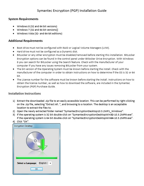
Symantec Encryption (PGP) Installation GuideSystem Requirements∙Windows 8 (32 and 64 bit versions)∙Windows 7 (32 and 64 bit versions)]∙Windows Vista (32- and 64-bit editions)Additional Requirements∙Boot drive must not be configured with RAID or Logical Volume Managers (LVM).∙Hard drive must not be configured as a Dynamic disk.∙BitLocker or any other encryption must be disabled/removed before starting this installation. BitLocker Encryption options can be found in the control panel under Bitlocker Drive Encryption. With Windows8 you can search for BitLocker using the Search feature. Check with the manufacturer of yourcomputer if you have any issues removing BitLocker from your system.∙The bit version of the Operating System must be known before starting the install. Check with the manufacturer of the computer in order to obtain instructions on how to determine if the OS is 32 or 64 bit.∙The License number for the software must be known before starting the install. Instructions on how to obtain the license number, as well as how to download the software, are included in the SymantecEncryption (PGP) Purchase Guide.Installation Instructions1)Extract the downloaded .zip file to an easily accessible location. This can be performed by right-clickingon the .zip file, selecting “Extract All..”, and browsing to a location. The desktop is an acceptablelocation to extract the files to.2)Open the newly extracted folder named “SymantecEncryptionDesktop10.3.2MP1_Windows”.3)If the operating system is 32 bit double-click on “SymantecEncryptionDesktopWin32-10.3.2MP9.exe”.If the operating system is 64 bit double-click on “SymantecEncryptionDesktopWin64-10.3.2MP9.exe”.4)Click “OK”.5)Select “I accept the license agreement” and click “Next”.6)Click “Next”.7)After the installation the following window will appear. Click “Yes” to reboot the machine in order tostart the configuration of the software.8)After the reboot is complete the following window will appear automatically. Click “Next” to regis terthe license for the Symantec Encryption Software.9)Enter in the License Number for the Symantec Encryption. Then click “Next”.10)Click “Next”.11)Make sure “I am a new user” is selected and click “Next”.12)This part of the wizard’s functionality is to setup a PGP key used to encrypt email messages. As this feature willnot be used, click “Skip” to avoid unnessesary steps in the configuration process.13)Uncheck “Automatically detect my email accounts” and click Next.14)Then click “Finish” to complete the initial configuration process.15)Now that the initial configuration is finished, a passphrase has to be created and the encryption needsto be started. In order to accomplish this, open Symantec Encryption Desktop. This can be achieved by right-clicking on the newly created icon of a lock in the bottom right corner of the screen on thetaskbar. Then click on “Open Symantec Encryption Desktop”.16)Click on “PGP Disk” and then click on “Encrypt Disk or Partition”.17)In order to setup the passphrase click “New Passphrase User…”.18)Click “Create New Passphrase” and then click “Next”.19)Click “Next”.20)Enter in a username into the “Username” field. This field may already be populated with the usernameof the Windows user that is currently logged on. This username is used to keep track of different Passphrases that can be used to logon to the system upon boot. After that is completed, proceed to the next step but do not click Next.21)It is time to fill out the Passphrase. The Passphrase is similar to a password. This Passphrase will needto be entered every time the machine is booted. Make sure that this Passphrase is not forgotten. If the Passphrase cannot be remembered the machine will not boot and the data on the hard drive will be lost. A recovery CD can only be used once to gain access to the machine in the event of a forgotten Passphrase. However, make sure that the Passphrase has a high quality as indicated by the percentage bar. After entering and re-entering the Passphrase, click “Next”.22)Click “Finish”.23)Now the hard drive can be encrypted. Click on the hard drive, or “Fixed Disk”, and then click “Encrypt”.24)Click “Yes”.25)A window appears similar to the following, except with a token unique to the machine that is beingencrypted. This token can be used with the Recovery CD in case the Passphrase is forgotten. This can only be used once. As stated, you may write this token down and store it in a safe place, but do not keep the token with the machine. Then click “OK”.26)The encryption process starts. Once you see the following window you may close the SymantecEncryption Desktop Application and the encryption process will continue in the background. The machine may be rebooted and used normally during the encryption process, which will take between 4-14 hours to complete. This step completes the installation and configuration process.When booting up the computer after the encryption process has been started, a screen similar to the one below will appear. The Passphrase that was configured will need to be entered at this point in order to continue the boot process. After inputting the Passphrase press the “Enter” key, and the system will boot into Windows.。
kmsoffline x64 v2.3.1激活教程
1、下载并安装好 kms 激活工具,进行压缩。 2、解压完后找到【kmseldi。exe】。 3、右击【以管理员身份运行】。 4、点击红色按钮。 5、按钮会变成灰色,等待激活后,重启电脑。 6、重启后,按【WIN+E 键】,打开【文件资源管理器】,选择 【此电脑】,右击【属性】。 7、在此界面可看到是否激活。 总结: 1、安装 kms 激活工具。 2、运行 kmseldi。exe。 3、点击红色按钮等待加激活。 4、在【此电脑】中确认是否激活。 Key Management Service(简称:KMS),这个功能是在 Windows Vista 之后的产品中的一种新型产品激活机制,目的是为了 Microsoft 更好的遏制非法软件授权行为(盗版)。
windows加密服务提供程序报告了错误
Windows加密服务提供程序报告了错误Windows操作系统提供了广泛的加密功能,从而保护用户的数据和隐私。
加密服务提供程序是Windows中负责处理加密相关任务的重要组件。
然而,有时候我们可能会遇到Windows加密服务提供程序报告错误的情况。
本文将指导您一步一步地解决这个问题。
步骤一:查看错误信息首先,我们需要了解具体的错误信息。
当Windows加密服务提供程序报告错误时,系统会显示相关的错误代码或错误描述。
这些信息能够帮助我们更好地理解问题的本质。
您可以在系统报错的弹窗中复制错误代码,然后在搜索引擎上进行搜索,以获得更多的解决方法和参考资料。
步骤二:重启加密服务有时候,Windows加密服务提供程序报告错误可能是由于服务本身出现了问题。
在这种情况下,重启加密服务可能是解决问题的有效办法。
1.打开“运行”对话框,可以通过按下Win+R组合键来快速打开该对话框。
2.输入“services.msc”并按下回车键,打开“服务”管理器。
3.在服务列表中,找到“加密服务”或“CryptSvc”。
4.右键点击该服务,选择“重新启动”。
现在,您可以尝试重新运行需要加密服务的应用程序,看看问题是否已经解决。
步骤三:检查依赖关系Windows加密服务提供程序依赖于其他一些系统组件和服务。
如果这些依赖关系出现了问题,可能会导致加密服务报错。
1.打开“服务”管理器。
2.找到“加密服务”或“CryptSvc”。
3.右键点击该服务,选择“属性”。
4.在属性窗口的“依赖”选项卡下,可以查看到加密服务的依赖关系列表。
确保这些依赖关系的相应服务都已启动,并且没有出现错误。
步骤四:修复系统文件有时候,加密服务报告错误可能是由于系统文件损坏引起的。
Windows操作系统提供了内置的系统文件修复工具,可以帮助我们解决这个问题。
1.打开命令提示符,可以通过按下Win+X组合键,然后选择“命令提示符”来快速打开。
2.在命令提示符窗口中,输入“sfc /scannow”并按下回车键。
关于WISPTIS.EXE进程!
关于WISPTIS.EXE进程!关于WISPTIS.EXE进程!2006-08-05 11:44 A.M.装完KAV6.0后,一打开OFFICE文档,KAV就跳出来提示有keybord键盘记录程序运行,查看一下知道是这个WISPTIS.EXE,本以为是什么木马窃听软件!上网查了下才知道是安装Micorosft Office或者Windows Update时候自带的程序。
因为程序本身不引用服务,所以无法在服务停止,如果从进程删除或直接删源文件,可能会造成下次打开OFFICE出现安装窗口,下面提供删除WISPTIS.EXE进程的解决法!WISPTIS - WISPTIS.EXE - 进程信息进程文件: WISPTIS 或者 WISPTIS.EXE进程名称:Windows Ink Services Platform Tablet Input Subsystem描述:WISPTIS.EXE是安装Micorosft Office或者Windows Update时候自带的程序。
删除该进程:把下面蓝色字的内容存为bat文件,可在记事本中另存为。
----------------------------------------rem -- UnRegister MS XP Tablet PC Ink Pen components@echo offset sys32=%SystemRoot%\System32set pfcfink=%CommonProgramFiles%\Microsoft Shared\INK "%sys32%\WispTis.exe" /unregserver"%sys32%\regsvr32.exe" /u /s "%sys32%\inked.dll" "%sys32%\regsvr32.exe" /u /s "%pfcfink%/inkobj.dll" "%sys32%\regsvr32.exe" /u /s "%pfcfink%/inkdiv.dll" "%sys32%\regsvr32.exe" /u /s "%pfcfink%/tpcps.dll" set pfcfink=set sys32=pause----------------------------------------保存后双击运行!!。
OFFICE 2010
Microsoft Office 2010 簡體中文專業版(MSDN官方正式版) 下載地址Microsoft Office 2010 簡體中文專業版(MSDN官方正式版) 下載地址 [轉貼2010-05-03 10:06:40]字號:大中小軟件大小:803 MB適用系統:WinXP (x86)/WinVista (x86)/Win7 (x86)/WinXP (x64)/WinVista (x64)/Win7 (x64)病毒檢測:該資源為微軟官方提供的MSDN 原版正式版Microsoft Office 2010 簡體中文專業版(包括32位和64位)的完整安裝包(安裝完成後,將MINI-KMS 激活軟件解壓到OFFICE 2010的根目錄下,運行激活即可。
),不是雲端軟件資源包。
請需要的朋友自行選擇下載。
安裝密鑰: 6QFDX-PYH2G-PPYFD-C7RJM-BBKQ8Microsoft Office 2010 簡介Microsoft Office 2010(以前使用代碼Office 14來提及)是Microsoft Windows下的生產力包Microsoft Office的下一個版本。
在2006年微軟完成Microsoft Office 12(也就是後來發布的Microsoft Office 2007)的時候就開始開發這套系統了。
主版本號沒有采用數字13,可能是由於恐十三癥。
之前曾經認為Office 2010(那時候叫做Office 14)會在2009年上半年發布,但是史蒂夫·巴爾默正式聲明Office 2010會在2010年發布。
根據InfoWorld在2006年4月發表的一篇文章來看,Office 2010將會比以前的版本更加“基於角色”。
文章引用了微軟企業及合作夥伴事業部副總裁Simon Witts的聲明,稱會為企業中不同的角色,如“研發人員、銷售人員和人力資源”提供定制的特性。
KMS图示激活操作过程
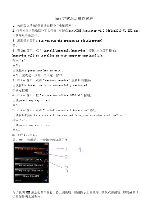
kms方式激活操作过程:1、关闭防火墙(确保激活过程中“电脑联网”)2、打开光盘内的激活补丁文件夹,右键点mini-KMS_Activator_v1.2_Office2010_VL_ENG.exe,以管理员身份运行。
3、出现提示窗口:did you run the program as administrator?是。
4、在kms窗口,点“ install/uninstall kmservice”按钮,出现窗口提示:kmservice will be installed on your computer.continue?(y/n):输入“Y”,回车;出现提示:press any key to exit...回车,完成这一步骤,关闭这一窗口。
5、在kms窗口,点击“restart service”重新启动服务;出现窗口:kmservice it is successfully restarted.按确定按钮。
6、在kms窗口,按“activation office 2010 VL”按钮,出现press any key to exit...回车。
7、在kms窗口,点击“install/uninstall kmservice”按钮。
出现窗口提示:kmservice will be removed from your computer.continue?(y/n):输入“y”,出现press any key to exit...回车。
8、关闭kms窗口。
五、KMS三步激活,一步卸载的简单图例:为了说明KMS激活的简单易行,特上图说明,请按图示上的顺序,依次点击按钮,即完成激活,但最好参照上述教程。
“迷你KMS”界面解释:1、Install/Uninstall KMService 安装/卸载KMS服务器2、Activate Office 2010 VL 激活Office 2010“大客户”版本3、Activation check Office 2010 检查Office 2010激活(状态)4、Key Manager Office 2010 VL 管理Office 2010“大客户”版本密钥5、Rearm Office 2010 重置Office 2010验证激活方法:打开一个组件例如EXCEL 2010点击文件---帮助---即可看到是显示激活的产品了。
KMS激活错误代码及解决方案
KSM激活错误代码及解决方案KSM Volume Activation 2.0 Technical Guidance当您尝试使用多个的激活密钥 (MAK) 或密钥管理服务 (KMS) 来对一个或多个基于 Windows Vista 的计算机执行批量激活时,您可能会收到错误代码。
本文讨论如何解决这些错误代码。
错误代码 0xC004C001症状尝试使用 MAK 激活一台或多台计算机时您可能会收到下面的错误信息:0xC004C001激活服务器确定指定的产品密钥无效原因如果 MAK 无效,可能会出现此问题。
解决方法要解决此问题,验证用于该密钥由 Microsoft 提供的 MAK。
要验证 MAK 有效,与宾夕法尼亚州呼叫中心。
回到顶端错误代码 0xC004C003症状尝试使用 MAK 激活一台或多台计算机时您可能会收到下面的错误信息:0xC004C003激活服务器确定指定的产品密钥被阻止。
如果 MAK 阻止激活服务器上,可能会出现此问题。
解决方法要解决此问题,与宾夕法尼亚州呼叫要获取新的 MAK 然后安装并激活系统的中心。
回到顶端错误代码 0xC004B100症状尝试使用 MAK 激活一台或多台计算机时您可能会收到下面的错误信息:0xC004B100激活服务器确定无法激活计算机。
原因如果 MAK 不受支持,可能会出现此问题。
解决方法要解决此问题,验证使用 MAK 的由 Microsoft 提供的 MAK。
要验证 MAK 有效,与宾夕法尼亚州呼叫中心。
回到顶端错误代码 0xC004C008症状尝试使用 KMS 激活一台或多台计算机时您可能会收到下面的错误信息:0xC004C008激活服务器确定无法使用指定的产品密钥。
如果 KMS 密钥已超过激活限制,可能会出现此问题。
KMS 密钥激活最多 10 次六个不同的计算机上。
解决方法如果需要更多的激活时间,请与宾夕法尼亚州呼叫中心。
回到顶端错误代码 0xC004C020症状尝试使用 MAK 激活一台或多台计算机时您可能会收到下面的错误信息:0xC004C020激活服务器报告多次激活密钥已超出限制。
“此操作只对目前安装的产品有效”的终极解决办法
“此操作只对目前安装的产品有效”的终极解决办法今天在Windows 7下安装软件新版本时,不小心误点了卸载旧版本安装进程界面的“取消”按钮。
导致再次运行安装程序的时候卡在了一个蛋疼的“此操作只对目前安装的产品有效"安装提示界面。
想到可能是刚才卸载进程中断,导致旧版本没卸载干净。
于是搜索注册表删除了大多数和SU相关的注册表信息,结果情况依然。
各种卸载软件测试一遍,均没有发现有旧版本的影子。
用谷歌搜索偶然发现这个帖子,收到启发,然后查看了msiexec这个命令的相关参数如下:msiexec /Option 〈Required Parameter> [Optional Parameter]安装选项</package | /i〉<Product.msi> 安装或配置产品/a <Product。
msi> 管理安装–在网络上安装产品/j<u|m> <Product.msi> [/t 〈Transform List>][/g 〈Language ID>] 公布产品– m 公布到所有用户,u 公布到当前用户〈/uninstall |/x〉〈Product。
msi |ProductCode> 卸载产品显示选项/quiet 安静模式,无用户交互/passive 无人参与模式–只显示进度栏/q[n|b|r|f] 设置用户界面级别n –无用户界面b –基本界面r –精简界面f –完整界面(默认值)/help 帮助信息重新启动选项/norestart 安装完成后不重新启动/promptrestart 必要时提示用户重新启动/forcerestart 安装后始终重新启动计算机日志选项/l[i|w|e|a|r|u|c|m|o|p|v|x|+|!|*]〈LogFile〉i –状态消息w –非致命警告e –所有错误消息a –操作的启动r –操作特定记录u –用户请求c –初始用户界面参数m –内存不足或致命退出信息o –磁盘空间不足消息p –终端属性v –详细输出x –额外调试信息+ –扩展到现有日志文件!–每一行刷新到日志* –记录所有信息,除了v 和x 选项/log 〈LogFile>与/l* 〈LogFile〉相同更新选项/update <Update1。
vistanita duplicate finder密钥 -回复
vistanita duplicate finder密钥-回复Vistanita Duplicate Finder密钥是一种用于授权和激活Vistanita Duplicate Finder软件的序列号。
在本文中,我们将一步一步地解释如何获取和使用Vistanita Duplicate Finder密钥。
首先,让我们先了解一下Vistanita Duplicate Finder是什么。
Vistanita Duplicate Finder是一款功能强大的文件和磁盘清理工具,旨在帮助用户在计算机上快速准确地查找和删除重复文件。
通过识别和删除重复的文件,用户可以释放磁盘空间,并提高系统的整体性能。
要使用Vistanita Duplicate Finder,用户需要先安装该软件。
可以从官方网站或其他可靠的软件下载站点下载安装程序。
一旦下载完成,用户可以双击安装程序来启动安装过程。
按照提示完成安装后,Vistanita Duplicate Finder将在计算机上成功安装并准备就绪。
现在让我们来讨论Vistanita Duplicate Finder密钥的获取和使用。
一种常见的方法是购买该软件并从官方渠道获取密钥。
用户可以在Vistanita官方网站上找到购买选项,并按照指示完成购买过程。
一旦购买完成,官方将向用户提供唯一的密钥,可用于激活Vistanita Duplicate Finder软件。
另外,用户还可以在一些第三方软件交易平台上购买Vistanita DuplicateFinder密钥。
这些平台通常提供各种软件产品的授权密钥和许可证。
但是在使用第三方平台进行购买时,用户应该特别注意选择可信赖和经过验证的平台,以确保获得合法有效的Vistanita Duplicate Finder密钥。
一旦获得了Vistanita Duplicate Finder密钥,用户可以在软件中进行激活。
首先,打开Vistanita Duplicate Finder软件。
- 1、下载文档前请自行甄别文档内容的完整性,平台不提供额外的编辑、内容补充、找答案等附加服务。
- 2、"仅部分预览"的文档,不可在线预览部分如存在完整性等问题,可反馈申请退款(可完整预览的文档不适用该条件!)。
- 3、如文档侵犯您的权益,请联系客服反馈,我们会尽快为您处理(人工客服工作时间:9:00-18:30)。
Appendix A: KMS Client Setup Keys
Computers that are running volume licensing editions of Windows 8,
Windows Server 2012, Windows 7, Windows Server 2008 R2, Windows Vista, and Windows Server 2008 are, by default, KMS clients with no
additional configuration needed. If you are converting a computer from a KMS host, MAK, or retail edition of Windows to a KMS client, install the applicable setup key (GVLK) from the following tables. Note
To install a client setup key, open an administrative command prompt on the client, type slmgr /ipk <setup key> and press ENTER. Windows Server 2012 and Windows 8
KMS Client Setup Key Windows 8 Professional NG4HW-VH26C-733KW-K6F98-J8CK4
Windows 8 Professional N XCVCF-2NXM9-723PB-MHCB7-2RYQQ
Windows 8 Enterprise 32JNW-9KQ84-P47T8-D8GGY-CWCK7
Windows 8 Enterprise N JMNMF-RHW7P-DMY6X-RF3DR-X2BQT
Windows Server 2012 Core BN3D2-R7TKB-3YPBD-8DRP2-27GG4
Windows Server 2012 Core N
8N2M2-HWPGY-7PGT9-HGDD8-GVGGY
Windows Server 2012 Core Single Language
2WN2H-YGCQR-KFX6K-CD6TF-84YXQ Windows Server 2012 Core Country Specific
4K36P-JN4VD-GDC6V-KDT89-DYFKP
Windows Server 2012 Server Standard XC9B7-NBPP2-83J2H-RHMBY-92BT4
Windows Server 2012 Standard Core XC9B7-NBPP2-83J2H-RHMBY-92BT4
Windows Server 2012 MultiPoint Standard HM7DN-YVMH3-46JC3-XYTG7-CYQJJ
Windows Server 2012 MultiPoint Premium XNH6W-2V9GX-RGJ4K-Y8X6F-QGJ2G
Windows Server 2012 Datacenter
48HP8-DN98B-MYWDG-T2DCC-8W83P
Windows Server 2012 Datacenter Core 48HP8-DN98B-MYWDG-T2DCC-8W83P
Windows 7 and Windows Server 2008 R2
KMS Client Setup Key
Windows 7 Professional FJ82H-XT6CR-J8D7P-XQJJ2-GPDD4
Windows 7 Professional N MRPKT-YTG23-K7D7T-X2JMM-QY7MG
Windows 7 Professional E W82YF-2Q76Y-63HXB-FGJG9-GF7QX
Windows 7 Enterprise 33PXH-7Y6KF-2VJC9-XBBR8-HVTHH
Windows 7 Enterprise N YDRBP-3D83W-TY26F-D46B2-XCKRJ
Windows 7 Enterprise E C29WB-22CC8-VJ326-GHFJW-H9DH4
Windows Server 2008 R2 Web 6TPJF-RBVHG-WBW2R-86QPH-6RTM4
Windows Server 2008 R2 HPC edition TT8MH-CG224-D3D7Q-498W2-9QCTX
Windows Server 2008 R2 Standard YC6KT-GKW9T-YTKYR-T4X34-R7VHC
Windows Server 2008 R2 Enterprise 489J6-VHDMP-X63PK-3K798-CPX3Y
Windows Server 2008 R2 Datacenter 74YFP-3QFB3-KQT8W-PMXWJ-7M648
Windows Server 2008 R2 for Itanium-based Systems GT63C-RJFQ3-4GMB6-BRFB9-CB83V
Windows Vista and Windows Server 2008KMS Client Setup Key
Windows Vista Business YFKBB-PQJJV-G996G-VWGXY-2V3X8
Windows Vista Business N HMBQG-8H2RH-C77VX-27R82-VMQBT
Windows Vista Enterprise VKK3X-68KWM-X2YGT-QR4M6-4BWMV
Windows Vista Enterprise N VTC42-BM838-43QHV-84HX6-XJXKV
Windows Web Server 2008 WYR28-R7TFJ-3X2YQ-YCY4H-M249D
Windows Server 2008 Standard TM24T-X9RMF-VWXK6-X8JC9-
BFGM2
Windows Server 2008 Standard without Hyper-V W7VD6-7JFBR-RX26B-YKQ3Y-6FFFJ
Windows Server 2008 Enterprise YQGMW-MPWTJ-34KDK-48M3W-X4Q6V
Windows Server 2008 Enterprise without Hyper-V 39BXF-X8Q23-P2WWT-38T2F-G3FPG
Windows Server 2008 HPC RCTX3-KWVHP-BR6TB-RB6DM-6X7HP
Windows Server 2008 Datacenter 7M67G-PC374-GR742-YH8V4-TCBY3
Windows Server 2008 Datacenter without Hyper-V 22XQ2-VRXRG-P8D42-K34TD-G3QQC
Windows Server 2008 for Itanium-Based Systems 4DWFP-JF3DJ-B7DTH-78FJB-PDRHK。
