FM8PC71AS 转CODE说明
国家工程实验室NI 9361 8通道差分计数输入模块说明书
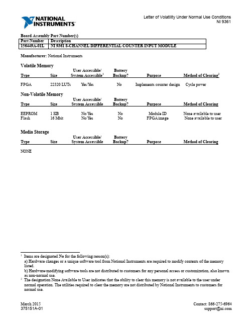
Manufacturer: National InstrumentsVolatile MemoryUser Accessible/ BatteryType Size System Accessible1Backup? Purpose Method of Clearing2 FPGA 22320 LUTs Yes/Yes No Implements counter design Cycle powerNon-Volatile MemoryUser Accessible/ BatteryType Size System Accessible Backup? Purpose Method of Clearing EEPROM 1 KB No/Yes No Module ID None available to user Flash 16 Mbit No/Yes No FPGA image None available to userMedia StorageUser Accessible/ BatteryType Size System Accessible Backup? Purpose Method of Clearing NONE1 Items are designated No for the following reason(s):a) Hardware changes or a unique software tool from National Instruments are required to modify contents of the memory listed.b) Hardware-modifying software tools are not distributed to customers for any personal access or customization, also known as non-normal use.2 The designation None Available to User indicates that the ability to clear this memory is not available to the user under normal operation. The utilities required to clear the memory are not distributed by National Instruments to customers for normal use.Terms and DefinitionsUser Accessible Allows the user to directly write or modify the contents of the memory during normal instrument operation.System Accessible Does not allow the user to access or modify the memory during normal instrument operation. However, system accessible memory may be accessed or modified by background processes. This can be something that is not deliberate by the user and can be a background driver implementation, such as storing application information in RAM to increase speed of use.Cycle Power The process of completely removing power from the device and its components. This process includes a complete shutdown of the PC and/or chassis containing the device; a reboot is not sufficient for the completion of this process. Volatile Memory Requires power to maintain the stored information. When power is removed from this memory, its contents are lost.Non-Volatile Retains its contents when power is removed. This type of memory typically contains calibration or chip configuration information, such as power up states.。
8COM中控说明书
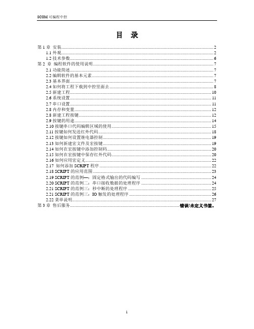
目录第1章安装 (2)1.1外观 (2)1.2技术参数 (6)第2 章编程软件的使用说明 (7)2.1功能简述 (7)2.2编辑软件的基本元素 (7)2.3基本界面 (7)2.4如何将工程下载到中控里面去 (8)2.5新建工程 (10)2.6系统设置 (11)2.7串口设置 (11)2.8内存和变量 (12)2.8新建工程按键 (12)2.9按键的用途 (14)2.10按键串口代码编辑区域的使用 (15)2.11按键如何发送红外代码 (18)2.12按键如何设置继电器控制 (19)2.13如何新建宏文件及宏按键 (19)2.14如何在宏按键中添加控制码 (20)2.15如何在宏按键中保存红外代码 (20)2.16如何应用宏定义 (22)2.17 如何添加SCRIPT程序 (22)2.18 SCRIPT的应用范围 (23)2.19 SCRIPT的范例—:固定格式输出的代码编写 (24)2.20 SCRIPT的范例二:串口接收数据的处理程序 (24)2.21 SCRIPT的范例三:秒中断的处理程序 (25)2.21 SCRIPT的范例三:IO触发的处理程序 (26)2.22菜单说明 (27)第3章售后服务.................................................................................................... 错误!未定义书签。
第1章 安装1.1外观1. 电源接口12V 的电源接口如图所示 2. COMPUTERCOMPUTER 端口为双向RS232端口,共有以下几个用途:1. 连接电脑时,通过电脑下载工程时,请使用本公司配置的白色编程线。
2. 可以用作默认的RFGW 连接端口,如果连接RFGW 的时候,请使用本公司配置的蓝色编程线,一端为9芯串行端连接COMPUTER 端口,一端是RJ45水晶头端口,连接RFGW 。
西门子SCALANCE X101-1LD IE媒体转换器用户手册说明书

Standards, specifications, approvals Standard ● for FM
● for hazardous zone ● for safety / from CSA and UL ● for hazardous zone / from CSA and UL
● for emitted interference ● for interference immunity Certificate of suitability ● CE marking ● C-Tick ● KC approval Marine classification association ● American Bureau of Shipping Europe Ltd. (ABS) ● Bureau Veritas (BV) ● Det Norske Veritas (DNV) ● Germanische Lloyd (GL) ● Lloyds Register of Shipping (LRS) ● Nippon Kaiji Kyokai (NK) ● Polski Rejestr Statkow (PRS) MTBF
字符编码之间的相互转换 UTF8与GBK
字符编码之间的相互转换UTF8与GBKC++ UTF8编码转换CChineseCode一预备知识1,字符:字符是抽象的最小文本单位。
它没有固定的形状(可能是一个字形),而且没有值。
“A”是一个字符,“€”(德国、法国和许多其他欧洲国家通用货币的标志)也是一个字符。
“中”“国”这是两个汉字字符。
字符仅仅代表一个符号,没有任何实际值的意义。
2,字符集:字符集是字符的集合。
例如,汉字字符是中国人最先发明的字符,在中文、日文、韩文和越南文的书写中使用。
这也说明了字符和字符集之间的关系,字符组成字符集(iso8859-1,GB2312/GBK,unicode)。
3,代码点:字符集中的每个字符都被分配到一个“代码点”。
每个代码点都有一个特定的唯一数值,称为标值。
该标量值通常用十六进制表示。
4,代码单元:在每种编码形式中,代码点被映射到一个或多个代码单元。
“代码单元”是各个编码方式中的单个单元。
代码单元的大小等效于特定编码方式的位数:UTF-8 :UTF-8 中的代码单元由8 位组成;在UTF-8 中,因为代码单元较小的缘故,每个代码点常常被映射到多个代码单元。
代码点将被映射到一个、两个、三个或四个代码单元;UTF-16 :UTF-16 中的代码单元由16 位组成;UTF-16 的代码单元大小是8 位代码单元的两倍。
所以,标量值小于U+10000 的代码点被编码到单个代码单元中;UTF-32:UTF-32 中的代码单元由32 位组成;UTF-32 中使用的32 位代码单元足够大,每个代码点都可编码为单个代码单元;GB18030:GB18030 中的代码单元由8 位组成;在GB18030 中,因为代码单元较小的缘故,每个代码点常常被映射到多个代码单元。
代码点将被映射到一个、两个或四个代码单元。
5,举例:“中国北京香蕉是个大笨蛋”这是我定义的aka字符集;各字符对应代码点为:北00000001京00000010香10000001蕉10000010是10000100个10001000大10010000笨10100000蛋11000000中00000100国00001000下面是我定义的zixia 编码方案(8位),可以看到它的编码中表示了aka字符集的所有字符对应的代码单元;北10000001 京10000010 香00000001 蕉00000010 是00000100 个00001000 大00010000 笨00100000 蛋01000000 中10000100 国10001000所谓文本文件就是我们按一定编码方式将二进制数据表示为对应的文本如00000001000000100000010000001000000100000010000001000000这样的文件。
FLX-MADI数字音频转换器用户手册说明书

ruUser's ManualTable of Contents1. QUICK REFERENCE (4)2. INTRODUCTION (5)2.1. Purpose (5)2.2. Box Contents (5)2.3. Conventions used in this manual (5)3. POSSIBLE SETUPS (6)3.1. Available AUX cards (6)3.2. Available FLX devices (7)3.3. FlexLink connection (7)4. AUDIO ROUTING (8)4.1. Modes and indication (8)4.2. Selecting the Route Mode (9)4.3. Remarks (9)5. CLOCK SETTINGS (10)5.1. Clock sources and indication (10)5.2. Selecting the Clock Source (10)6. ACCESSING INTERNALS (12)6.1. Opening the device (12)6.2. Inside view (12)6.3. Installing AUX cards (12)7. DIP SETTINGS (13)7.1. Base device config (DIP1..3) (13)7.2. AUX config (DIP4..6) (14)7.3. FlexLink channel mapping (DIP7..9) (15)8. SPECIAL OPERATING MODES (16)8.1. Version Display (16)8.2. LED Test (16)8.3. Interface Self-Test (16)8.4. Firmware update (17)9. SPECIFICATIONS (18)10. ACCESSORIES (18)10.1. Rack mount kits (18)10.2. Additional (redundant) power supply (18)11. APPENDIX (19)11.1. Warranty (19)11.2. Manufacturer contact (19)11.3. FCC Compliance (19)11.4. Recycling (20)FLX-MADI 11.5. Document Revision History (20)11.6. About this document (20)User's Manual1. QUICK REFERENCE➊Power switch and "power good" indicators.LEDs light up blue when power is available on the respective port.➋Mode indicators/selector. Long-press the "Select" button to change the audio routing between the interfaces. Wait four seconds to activate the selected mode.➌Clock indicators/selector. Long-press the "Select" button to change the clock source and sample-rate. Wait four seconds to activate the selected mode.➍MADI SFP port. Pre-installed 1310nm Multimode SFP, accepts any other SFPs Compatible to standard MADI optical (SC plugs) using an LC-to-SC adapter cable ➎MADI Coaxial port➏AUX slot. Accepts optional card for standalone use, or additional MADI channels ➐DIP switches, mostly to control output data format. See 7 . DIP Settings➑USB port (firmware update only, no audio)➒Redundant DC input ports➓FlexLink: optional connection to second flexiverter, or to multiverter.FLX-MADI2. INTRODUCTION2.1.PurposeThe FLX-MADI device is as digital audio converter, providing two built-in MADIinterfaces and a third one (or many other interfaces) with optional AUX cards. Itcan be used in different setups, depending on the user's needs:standalone, to convert between the built-in MADI ports (media converter),standalone, to convert between one of the built-in MADI ports and an additionalAUX card (MADI-to-anything),together with another flexiverter, connected via FlexLink (for up to 192x192channels),together with the multiverter, connected via FlexLink. This provides remotecontrol, channel-wise routing and SRC (Sample Rate Conversion).For a detailed description of possible configurations see 3 . Possible Setups.2.2.Box Contents1 FLX-MADI Converter1 HDMI cable 0.5m / 1.7 ft with locking screws1 Power supply1 Power cord (country specific)This manual2.3.Conventions used in this manualA button on the front is shown like this: Mode or ClockA LED is shown like this:◌ off / ⬤on / ❇ blinkingA section marked with an "information" icon indicatesa useful tip.User's Manual3. POSSIBLE SETUPSThe device can be used in three different setups, shown below:3.1.Available AUX cardsAt the time of writing (2021-11), the following AUX cards are available. More will come, please check www.appsys.ch for updates.FLX-MADIAUX-AVB116x16ch / 32x0ch / 0x32ch MILAN-approved AVBAUX-DAC18ch analog outputs (1xDB25)AUX-DANTE64x64ch DANTE network cardAUX-MADI-COAX64x64ch MADI for coaxial cable (BNC connectors)AUX-MADI-OPTO64x64ch MADI optical, SC connector (Multimode 125um 1310 nm)AUX-MADI-SFP64x64ch MADI for SFP (Small-Factor Pluggable) modulesAUX-WORDCLOCK BNC wordclock I/O3.2.Available FLX devicesAt the time of writing (2021-11), the following FLX devices are available. More willcome, please check www.appsys.ch for updates.3.3.FlexLink connectionThe FlexLink connection is designed to connect Flexiverters with each other, orwith the Multiverter. It provides:192x192 channels bi-directional transmission of 24-bit uncompressed audio(fully transparent to AES3 compatible metadata bits)Super-low link latency of 4 samples (ca. 83µs)Dedicated, high-quality reference clock signal with automatic configurationPower supply for connected devices (to reduce cabling), alternatively serves asredundancy scheme when both devices are powered: in case of power failure,both devices keep working from the remaining power supply.Uses standard HDMI cables (with locking screws), to provide easy fieldreplacement in case of defects.1Estimated availability: Q1/2022User's Manual4. AUDIO ROUTINGThe flexiverter can operate in various routing modes, allowing you to pass audiobetween the available interfaces (MADI SFP, MADI coaxial, AUX and FlexLink) inmany different ways. The LEDs in the "MODE" section indicate the involvedinterfaces.4.1.Modes and indication2All incoming data is also split (output) to FlexLink: MADI SFP is split to Lane 1 (ch1-64), MADI coaxial is split to Lane 2 (ch65-128) and AUX is split to Lane 3 (ch129-192). The split is not indicated on the LEDs for clarity but is always active.FLX-MADIseconds, the selected mode is applied automatically.4.2.Selecting the Route ModeLong-press the Mode button until the LEDs are blinking yellow.Current routing mode is shown by alternately yellow blinking LEDs, indicatingthe interfaces where the signal is passed between.Press the Mode button repeatedly to cycle between available modes, untilthe desired mode is shown.After four seconds without interaction, selection mode is terminated and thecurrent setting comes into effect.4.3.RemarksRouting between the selected interfaces is always bi-directional, meaning thataudio is passed between them both ways. A working bi-directional link shows⬤green for both interfaces. If the LED shows ⚪white, the correspondinginterface does only output data but no input on it has been detected. If the LEDshows ⬤ red, the interface is not connected, or the clock is invalid or missing.Channel-wise routing and splitting (crosspoint switch/matrix) between allchannels is possible when the flexiverter is connected to a multiverter. Routingis then done via the multiverter's web interface or via the command line.User's Manual5. CLOCK SETTINGS5.1.Clock sources and indicationThe flexiverter can be clocked from every interface (acting as clock slave), or canrun on its internal clock (acting as clock master).5.2.Selecting the Clock SourceLong-press the Clock button until the LEDs are blinking yellow.Current clock source/modes is shown by blinking LED(s).Press the Clock button repeatedly to cycle between the available clock sources. Depending on the source, you might need to select the desired sample rate (❇44.1 kHz or ❇48 kHz) and/or the appropriate multipliers (❇x2 /❇x4).After four seconds without interaction, clock setting is automatically terminated and the selected clock source comes into effect.6. ACCESSING INTERNALS6.1.Opening the deviceRequired: Torx T10 screwdriver.Power off the device and detach all cables to avoid short-circuit or damage.Detach the device from the rack-mount kit.Remove the four top screws and the top cover by pulling it upwards:6.2.Inside view➊Screws for AUX cover plate➋AUX card connector6.3.Installing AUX cardsRemove the screws holding the cover plate, and the blank cover plate ➊Insert the AUX card from inside, using the supplied cover plate.Make sure it is correctly fitted to the card connector➋Secure the card using two cover screws ➊The card has been installed correctly if you are able to select an audio routingmode involving AUX (long-press MODE button to enter Route Mode Selection).7. DIP SETTINGSFine-tuning of the flexiverter's built-in interface behavior and of the AUX card canbe achieved via DIP settings on the back side. Changing the DIP settings will come immediately into effect. Default setting: all switches up.7.1.Base device config (DIP1..3)The configuration below affects only the MADI outputs. The input format isautomatically detected, independent of the DIP switch settings.7.2.AUX config (DIP4..6)Many AUX card provide additional settings, which can be adjusted using theseswitches. The actual meaning depends on the type of AUX card installed:For cards not listed, refer to the manual of the respective card, or check for anewer version of this manual.3Applies to outputs only. Input format is always auto-detected, regardless of the switch setting7.3.FlexLink channel mapping (DIP7..9)The FlexLink interface can transmit 192x192 channels, organized in three laneswith 64 channels each. The channel assignment can be adjusted to meet the user's needs, particularly when the device is used in double-FLX configuration (to makesure that all interfaces and channels are mapped to the desired target on the peerFLX device.8. SPECIAL OPERATING MODESSpecial operating modes are accessible by holding down the Mode button while switching on the device. Press Mode again to switch to the next mode:Version Display ⇨ LED Test ⇨ Interface Self-Test ⇨ Normal operation 8.1.Version DisplayThe firmware version "X.Y" and the hardware version "Z" are shown on theLEDs on the front panel:- The number of ⬤pink LEDs lit indicate the major firmware number "X"- The number of ⬤orange LEDs lit indicate the minor firmware number "Y"- The number of ⬤green LEDs lit indicate the hardware version "Z"Example: One (1) ⬤pink LED and three (3) ⬤⬤⬤orange LEDs means"Firmware 1.3", zero green LEDs mean HW version 0.Blinking LEDs mean that the currently installed firmware is a "beta" version. Itis advised to upgrade to an official release version as soon as it is released.Press Mode again to proceed to LED test.8.2.LED TestAll LEDs on the front and on the back should show ⚪ white.Press Mode again to proceed to Interface Self-Test.8.3.Interface Self-TestAll built-in interfaces and the optional AUX card can be tested for correct operation by the user. This is done using the special self-test mode, in which the deviceoutputs a special random test pattern on all channels. This pattern is looped backvia an external cable into the corresponding inputs, where it is checked forconsistency.Self-test mode is indicated with "CLOCK"showing INT/48kHz in ⬤cyan color.The "MODE" LEDs indicate ⬤red (error/no connection) or ⬤green (loopbackdata received ok) for the respective interface.Connect the Output to the Input of the MADI SFP Port using an optical cable.Connect the Output to the Input of the MADI Coaxial Port using an coaxial(BNC) cable with 75 Ohms impedance.If an AUX card is installed, connect all output ports of the AUX card to therespective inputs using a loop-back cable. Note: NOT supported with AUX-ADC, AUX-AES67, AUX-AVB, AUX-DANTE.8.4.Firmware updateThe firmware can be updated from any Windows PC over the rear USB port.▶To update:Download the latest firmware from www.appsys.ch/FLX- MADIUnpack the firmware package FLX-MADI-Firmware_x.y.zipConnect your PC via USB to the flexiverterPower ON the deviceRun the FLX-MADI_Updater.bat file from the firmware package and follow theinstructions on the screen.Power cycle the device to effect the update.Thanks to the special design of the updater, it is virtuallyimpossible to damage ("brick") the device during update. Ifupdating fails or is interrupted, restart the procedure. You canalso can go back to any older firmware version at any time.9. SPECIFICATIONS10. ACCESSORIES10.1.Rack mount kitsFor integration in 19" racks, two kinds of rack mount kits / brackets are available:RM-FLX1: For mounting one FLX device into 1U 19" spaceRM-FLX2: For mounting two FLX devices into 1U 19" space10.2.Additional (redundant) power supplyPWR-FLX: Additional power supply to provide redundancy for single-FLXconfigurationsFlexLink Cable 0.5m. HDMI cable with locking screws11. APPENDIX11.1.WarrantyWe offer a full two (2) year warranty from the date of purchase. Within this period,we repair or exchange your device free of charge in case of any defect*. If youexperience any problems, please contact us first. We try hard to solve your problem as soon as possible, even after the warranty period.* Not covered by the warranty are any damages resulting out of improper use,willful damage, normal wear-out (especially of the connectors) or connection withincompatible devices.11.2.Manufacturer contactAppsys ProAudioRolf Eichenseher Bullingerstr. 63 / BK241 CH-8004 Zürich Switzerland www.appsys.ch**************Phone: +41 43 537 28 51 Mobile: +41 76 747 07 4211.3.FCC ComplianceThis equipment has been tested and found to comply with the limits for a class Bdigital device, pursuant to part 15 of the FCC Rules. These limits are designed toprovide reasonable protection against harmful interference in a residentialinstallation. This equipment generates, uses and can radiate radio frequency energy and if not installed and used in accordance with the instructions, may causeharmful interference to radio communications. However, there is no guarantee thatinterference will not occur in a particular installation. If this equipment does causeharmful interference to radio or television reception, which can be determined byturning the equipment off and on, the user is encouraged to try to correct theinterference by one or more of the following measures:Reorient or relocate the receiving antennaIncrease the separation between the equipment and receiverConnect the equipment into an outlet on a circuit different from that to whichthe receiver is connectedConsult the dealer or an experienced radio/TV technician for helpFLX-MADI This equipment has been verified to comply with the limits for a class B computingdevice, pursuant to FCC Rules. In order to maintain compliance with FCCregulations, shielded cables must be used with this equipment. Operation with non-approved equipment or unshielded cables is likely to result in interference to radioand TV reception. The user is cautioned that changes and modifications made tothe equipment without the approval of manufacturer could void the user’s authorityto operate this equipment.11.4.RecyclingAccording to EU directive 2002/96/EU, electronic devices with acrossed-out dustbin may not be disposed into normal domesticwaste. Please return the products back for environment-friendlyrecycling, we'll refund you the shipping fees.11.5.Document Revision History1: Initial release11.6.About this documentAll trademarks mentioned in this document are property of the respective owners.All information provided here is subject to change without prior notice.Document Revision: 1 · 2021-11-29Copyright © 2021 Appsys ProAudio · Printed in SwitzerlandIDENT 9.00.16146.00User's ManualDeclaration of ConformityThe manufacturer:Appsys ProAudioRolf EichenseherBullingerstr. 63 BK 241CH-8004 ZürichSwitzerlanddeclares under sole responsibility that the products mentioned below:Flexiverter FLX-MADImeet the requirements of the following standards:EN 55024:2010EN 55032:2015 Class BEN 61000-3-2:2006/A1/A2:2009EN 61000-3-3:2009EN 61000-6-3:2007/A1:2011Therefore the product fulfills the demand of the following EC directives:73/23/EWG(Directive related to electrical equipment designed for use within certain voltage limits)89/336/EWG(Directive related to electromagnetic compatibility)The devices are marked accordingly.Zürich, 21.11.2021Rolf Eichenseher (CEO)。
RocketLinx MC7001 工业级以太网到光纤媒体转换器说明书

Quick Installation GuideROCKET LINX MC7001Industrial Ethernet to Fiber Media ConverterThe RocketLinx MC7001 industrial Ethernet to fiber media converter conforms to IEEE 802.3 and IEEE 802.3u standards with one 10/100BASE-TX and one 100BASE-FX Fast Ethernet fiber port. The MC7001 features a slim and compact industrial design to save DIN rail space for compact installations. In order to perform under harsh environments, the MC7001 is housed in an industrial-grade aluminum case with IP31 standard protection.The 4-Pin DIP switch configures the MC7001 to operate in switch mode or pure converter mode.Package ChecklistMC7001 industrial media converter Quick Installation GuideMounting the RocketLinx MC7001Mount the DIN rail clip on the rear of the MC7001 to the DIN rail.Grounding the RocketLinx MC7001There is a grounding screw on the bottom side of the MC7001. As shown in the picture, connect the ground screw of the MC7001 to a grounding surface to ensure safety and prevent noise.IntroductionThe power input provides polarity reverse protection to avoid system damage. 1. Insert the positive and negative wires into the V+ and V- contact on the terminal block connector.2. Tighten the wire-clamp screws to prevent the power wires from being loosened.Note: The recommended working voltage is 24VDC (18-32VDC) or 18VAC (18-27VAC)Wiring the Power Inputsavoid system damage. 8-32VDC) or 18VAC (18-27VAC)Accepts 12-24AWG wire.The MC7001 providespolarity reverse protectionV-V+h mode or pure.RocketLinx MC7001Connecting to the Network1. Connecting the Ethernet Port: Connect one end of an Ethernet cable into the RJ45 port of the MC7001, and the other end is attached to a networking device. The RJ45 port supports Auto MDI/MDIX functionality. The TP LED will turn on and flash to indicate RJ45 port’s link and activity.2. Connecting the Fiber Port: Connect the fiber port on your MC7001 to another fiber Ethernet device, by following the figure below. Wrong connection or fiber cable type will cause the fiber port to not function properly.This is a Class 1 Laser/LED product. Don't stare into the Laser/LED Beam.Cable Wiring(SC to SC)RX A TX BTX A RX B A B3. For different link distances, the MC7001 provides Multi-Mode fiber and Single-Mode fiber models. The table below illustrates fiber transceiver specifications. The fiber connector is a standard connector or square connector (SC). To ensure your fiber converter cantransmit/receive data between the 2 nodes, the attenuation of the optical fiber cable should not exceed the fiber converter’s Link Budget.Mode Cable Type Wavelength Transmit Power(min.)TransmitPower (max.)Receive Sensitivity (max.)Receive Sensitivity (min.)Min. Launch Power –Max. Receive SensitivityDistance(km)Multi 50/125um 62.5/125um1310nm -20dBm -14dBm -31dBm 0dBm 11dBm2km Note (below)Single 8-10/125um 1310nm -15dBm -8dBm -34dBm -8dBm 19dBm30kmNote: In the IEEE standard, it suggests the available transmission distance is 2KM for 62.5/125um fiber optical cable in 1310nm wave length. Actually, the attenuation of Multi-Mode 62.5/125um optical fiber cable is 1.5dBm/km and the maximum link distance can up to 4 to 5km.IEEE organization recommends maximum optical fiber cable distances as defined in thefollowing table:Standard Data Rate (Mbps) Cable Type IEEE StandardDistance 100Base-FX 100 1310nm, 50/125um or 62.5/125umMulti-Mode optical fiber cable2km100Base-SX 100 850nm, 50/125um or 62.5/125umMulti-Mode optical fiber cable300m1000Base-SX 1000850nm, 50/125umMulti-Mode optical fiber cable850nm, 62.5/125umMulti-Mode optical fiber cable550m220m1000Base-LX 10001310nm, 50/125um or 62.5/125umMulti-Mode optical fiber cable1310nm, 9/125umSingle-Mode optical fiber cable550m5km1000Base-LH 1000 1550nm,9/125umSingle-Mode optical fiber cable70kmThe following table provides information about optical fiber cable attenuation:DIP Switch SettingNote: After adjusting the DIP-switch, reboot the MC7001 to activate the new settings.LED FunctionsComtrol Customer Service。
0832 8位模拟数字转换器说明书
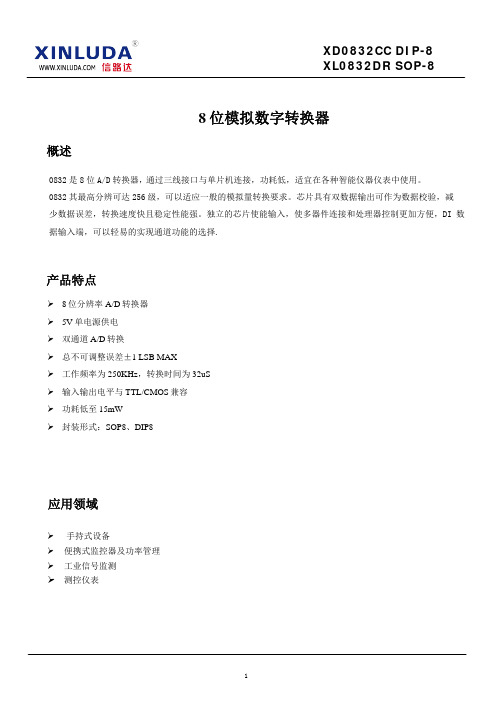
8位模拟数字转换器概述0832是8位A/D转换器,通过三线接口与单片机连接,功耗低,适宜在各种智能仪器仪表中使用。
0832其最高分辨可达256级,可以适应一般的模拟量转换要求。
芯片具有双数据输出可作为数据校验,减少数据误差,转换速度快且稳定性能强。
独立的芯片使能输入,使多器件连接和处理器控制更加方便,DI 数据输入端,可以轻易的实现通道功能的选择.产品特点8位分辨率A/D转换器5V单电源供电双通道A/D转换总不可调整误差±1 LSB MAX工作频率为250KHz,转换时间为32uS输入输出电平与TTL/CMOS兼容功耗低至15mW封装形式:SOP8、DIP8应用领域手持式设备便携式监控器及功率管理工业信号监测测控仪表引脚示意图及说明DIP-8/SOP-8(TOP VIEW)CS VCC/REFCH0CLKCH1 DOGND DI序号管脚名称管脚功能1CS 片选使能,低电平有效2CH0模拟输入通道,可作为IN+/IN-使用CH1模拟输入通道,可作为IN+/IN-使用34GND电源地5DI通道选择控制,数据信号输入端。
6DO数据转换接口输出端7CLK时钟输入端8VCC/REF电源正端输入及基准电压输入极限参数VCC端到GND 电压......................................................................................................................... -0.5V to 6.5V所有数字管脚到GND 电压...................................................................................................... -0.3V to VCC+0.3V所有模拟管脚到GND电压 ...................................................................................................... -0.3V to VCC+0.3V所有输入管脚峰值电流 .................................................................................................................................. 15mA存储温度 ....................................................................................................................................... -65℃ to +150℃工作环境温度 ................................................................................................................................. -40℃ to +85℃焊接温度(10 秒) (260)最高结温 (150)扩散功耗 ............................................................................................................................................................ 0.8WESD耐压 (2000V)电特性(除非特别说明,VDD =5.5V,T A =25o C)符号 参数说明 测试条件 最小值 典型值 最大值 单位VCC Power Supply 4.5 6.3 VICC Supply Current 0.922.5mA VIH Logical “1” Input Voltage (Min) VCC=5.25V 2 2VVIL VIN(0), Logical “0” Input Voltage (Max) VCC=4.75V 0.8VIIH IIN(1), Logical “1” Input Current (Max) VIN=5.0V 0.005 1 µA IIL IIN(0), Logical “0” Input Current (Max) VIN=0V −0.005 −1 µAVOH VOUT(1), Logical “1” Output Voltage (Min) VCC=4.75VIOUT=−360 µA 2.4V IOUT=−10 µA 4.5VVOL VOUT(0), Logical “0” Output Voltage (Max) VCC=4.75V0.4V IOUT=1.6 mAISOURCE Output Source Current (Min) VOUT=0V −14 −6.5 mA ISINK Output Sink Current (Min) VOUT=VCC 168fCLK Clock Frequency Min Max 10 400 kHztC Conversion Time Not including MUXAddressing Time8 1/fCLKClock Duty Cycle 4060%tSET-UP CS Falling Edge or Data Input Valid to CLKRising Edge250 nstHOLD Data Input Valid after CLK Rising Edge 90nstpd1, tpd0 CLK Falling Edge to Output Data Valid CL=100 pFData MSB First 650 1500 ns Data LSB First 250 600 nst1H, t0H Rising Edge of CS to Data Output and SARS Hi–ZCL=10 pF, RL=10k 125 250 nsCL=100 pf, RL=2k 500 nsC IN Capacitance of Logic Input 5 pF C OUT Capacitance of Logic Outputs 5 pF功能说明及时序图0832使用采样-数据-比较器的结构,采用逐次逼近方式进行转换,根据多路器的软件配置,单端输入方式下,要转换的输入电压连接到输入端和地端;在差分输入方式下,两个输入端可以分配为电源的正极和负极,由DI端进行配置。
atv71Modbus手册
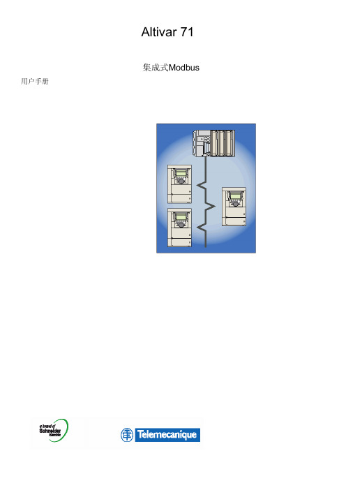
危险 危险电压 • 在安装或操作Altivar 71 变频器之前请您阅读并了解此手册。只有专业人员才能对此变频器进行安装、调节、修理与维护。 • 用户应对与所有设备的保护地有关的大量国际和国内电气标准相符合进行负责。 • 此变频器的许多零件,包括印刷电路板,在线电压下工作,不能触摸这些零件,只能使用绝缘工具。 • 不能触摸那些未受保护的元件或带电的接线螺钉。 • 不能将PA端与PC端或直流总线电容器短接。 • 在通电或启动与停止变频器之前应安装并关上所有机盖。 • 在对变频器进行维修之前
- 断开所有电源。 - 在变频器的断路器上放置一个 "严禁合闸"的标签。 - 将断路器锁定在打开位置。 • 维修变频器之前应断开所有电源,包括可能会带电的外部控制电源。直流总线电容器放电须等待15分钟,然后按照安装手册 给出的直流总线电压测量程序来检查直流电压是否小于45Vdc。变频器的LED并不是有无直流总线电压的精确指示器。
用户手册
Altivar 71
集成式Modbus
பைடு நூலகம்
目录
开始之前_________________________________________________________________________________________________4 文档结构________________________________________________________________________________________________ 5 引言____________________________________________________________________________________________________ 6
8路ASI输入综合调制器说明书
综合调制器使用说明书目录1安全注意事项 (2)2概述 (3)2.1产品功能及用途 (3)2.2外形尺寸(1U机箱) (3)3主要特点 (4)4技术规格与指标 (4)4.1ASI接口 (5)4.2射频接口 (5)4.2.1射频输出 (5)4.2.2射频测试输出 (5)4.3信号通道编码 (6)4.4网管接口 (6)4.5辐射及安全要求 (6)5系统组成及工作原理 (6)5.1系统组成 (6)5.2工作原理 (8)6安装指南 (8)6.1安装准备 (8)6.2设备安装流程 (8)6.3环境条件要求 (8)6.4接地要求 (9)6.4.1机柜接地 (9)6.4.2设备接地 (10)6.5线缆的连接 (10)6.5.1电源线的连接 (10)6.5.2信号线的连接 (10)7前面板操作指南 (10)7.1键盘功能 (10)7.2菜单选择 (11)7.2.1锁定状态显示 (11)7.2.2主菜单显示 (11)7.2.1输出设置 (11)7.2.2网络设置 (14)7.2.3保存当前设置 (14)7.2.4加载设置 (15)7.2.5版本号 (15)7.2.6选择语言种类(中文和英文) (15)7.2.7错误信息 (15)7.3系统运行错误及排除 (16)7.3.1指示灯状态 (16)7.3.2常见故障排除 (16)8网络管理器操作指南 (16)8.1NMS登陆 (18)8.2添加频点 (19)8.3添加设备 (20)8.4修改设备 (21)8.5查看和设置设备参数 (23)8.5.1调制设置 (24)8.5.2通道复用 (25)8.5.3加扰设置 (26)8.5.4NIT编辑 (27)8.5.5PID透传 (28)8.5.6PSI编辑 (29)8.6网管软件公共功能 (31)前言感谢您选用本公司的产品。
本手册详细介绍了产品的性能、安装及操作方法,无论您是第一次使用该产品,还是以前接触过很多类似产品,都必须在使用前仔细阅读本手册。
Fincoil FMP和FMPG FMP空气冷却器及FMPG液体循环空气冷却器的说明说明书

FMP air coolers and FMPG liquid circulated air coolers are designed for cold rooms where low profi le dual discharge air cooler is needed. Units are also suitable for cooling engine rooms and monitoring rooms. The range includes CA-models with copper tubes designed for refrigerants and liquids, which do not corrode copper and SA-models with stainless steel tubes suitable for NH 3 and for conditions requiring special cor-rosion protection. To applications, where adjustable air throw fi gure and isolated drip tray design is needed, we recommend Polar Bear Duo range and for special conditions AMK range air coolers with hot dip galvanized heat transfer section.Features– 12 sizes with nominal capacities from 3.06...73.1 kW (R404A, SC2, EN 328)– Performance data of air coolers according to Eurovent Rating Standard 7/C/001– Fan sizes Ø 450 mm and Ø 500 mm with four fanspeed alternatives, fan size Ø 630 mm with two fan speed alternatives– In evaporator use inside grooved Cross Hatch-tube, smooth tubes in liquid use– Hygienic construction; the casing is made of polyester coated, hot dip galvanized steel. The unit can be tightly installed to the ceiling.– Double, uninsulated drip trays, which are easy to open and remove– Product selection with the FincoilSelect program2Technical dataThe heat transfer section is made of aluminium fi ns and copper tubes (CA) with 4 mm, 7 mm or 12 mm fi n spacing or stainless steel tubes (SA) with 4 mm or 7 mm fi n spacing. As an option, aluminium fi ns with epoxy coating are also available with 4 mm fi n spacing (please check electric defrost capacity). The capacity correction factor for heat transfer capacity of epoxy-coated aluminium is 0.97. Casing material is polyester coated hot dip galvanized steel, colourwhite NCS 1002-4. CA-models are with direct expansion as standard and SA-models with pump circulation as standard. Double, uninsulated drip trays are easy to open and remove for cleaning. Units have electric defrost as well as hot gas defrost as alternative. A reliable, energy saving defrost heating element is used in the tray defrost.A manual including installation and service instructions is shipped with each unit.Options SS = electric defrost in coil and tray SSA = electric defrost in tray only KK-SSA = hot gas defrost in coil, electric defrost in tray RSt = casing of stainless steel Ep = epoxy coated fi ns, 4 mm fi n spacing only Q = fans’ safety switches mounted beside fans W = fans wired to the junction box at the cooler end Pc = pump circulation (CA)DX = direct expansion for R717 (SA)A = air suction through the coil block, blowing direction downwards Y = air suction from above, blowing sidewards (mounting minimum 300 mm from the ceiling)3FansThe standard motors are suitable for 3/400 V/50 Hz power supply. Suitability for other power supplies has to be checked separately. The minimum operating temperature for fan motors is –50°C. In the standard model the air suction is from below and blowing sidewards. Technical information for other power supplies is available separately.Fan power input in the performance data tables is givenat +20°C temperature. Full load current (FLC) is given for temperature of –30°C. The current value changes according to air density. The data may also vary due to changes in motor types; therefore the overload protectors should have a +/–20% adjustment margin. Fan speed can be regulated by changing the voltage, excluding fan Ø 630 mm, which canbe regulated by a frequency converter. The fan speed can be reduced by changing delta connection (D) into star connection (Y), excluding fan Ø 630 mm.The fans have internal thermal protectors wired to fans’ junction boxes. If they are connected to control the contactor, an external overload protector is not needed (excluding fanØ 630 mm). The protection class of fans is IP54.Performance dataThe capacities and air fl ows shown in the Polar Power selection program and in the tables in this brochure arecertifi ed with the Eurovent Certify All-certifi cation, and verifi ed by tests (EN 328) in independent laboratories.The performance data of the air coolers is given for the refrigerant R404A, with standard condition SC2 (te= -8 ºC,ΔT1= 8 K, RH = 85%). The infl uence of humidity is includedin the nominal capacities. The performance data is given at the sea level and with normal atmospheric pressure. Air throw is given with 7 mm fi n spacing, 1400 rpm fan speed andfi nal air velocity 0.5 m/s. The air throw realizes in isothermal conditions and with undisturbed fl ow. The air throw changes according to air current. The maximum air throw can vary from the middle line depending on for example location of shelves and lamps.Lwais the A-stressed sound power level [dB(A)]. Sound pressure level Lpa[dB(A)] is given in a room with absorption area of 100m2 (Sabine), with observation point at a distanceof 5 meters and 45º horizontally below the middle point of the fans.SelectionThe preliminary air cooler selection can be made using the tables in this leafl et. Capacities for the required refrigerantand temperature difference can be calculated with the helpof the correction factors. The exact selection is made by FincoilSelect software, which is available either on CD-rom or on our web page www.fi ncoil.fi .Selection of circuiting and liquid distributor for air coolers is made according to each specifi c dimensioning condition and refrigerant. If the circuiting is unknown, following informationis needed: refrigerant, cooling capacity, evaporation temperature, air inlet temperature, relative humidity and incoming liquid temperature (if lower than +20ºC). In the selection of liquid circulated air coolers is following information needed: cooling capacity, liquid / concentration, liquid temperature in/ out, air inlet temperature / relative humidity, max. allowed liquid pressure drop and allowed sound level in a nominal point. Our sales department will help you with the selection, if the needed conditions are outside of the selection program’s operations area.Performance data FMPR404A, SC2, EN 328 3/400 V/50 HzCorrection factors for evaporating capacity R404A Air throw with 7 mm fin spacingAir throw is given withfinal air velocity 0.5 m/s.Capacities for different refrigerantsInfluence of humidity on the capacityFixed ratios specified in the Eurovent Standard to convertthe standard capacity (dry capacity), which is measuredaccording to EN 328, into the nominal capacity (wetcapacity) suitable for practical conditions.Technical data of fan motors 3/400 V/50 HzElectric defrost capacities for 3/400 V and 3/230 VERC00188EN 0805Alfa Laval reserves the right to change specifi cation without prior notifi cation. www.fi ncoil.fiDimensional drawings1) J 2) S connecting lead.3) FDimensions and weight。
广播系统-LAF-C系列主机使用说明书
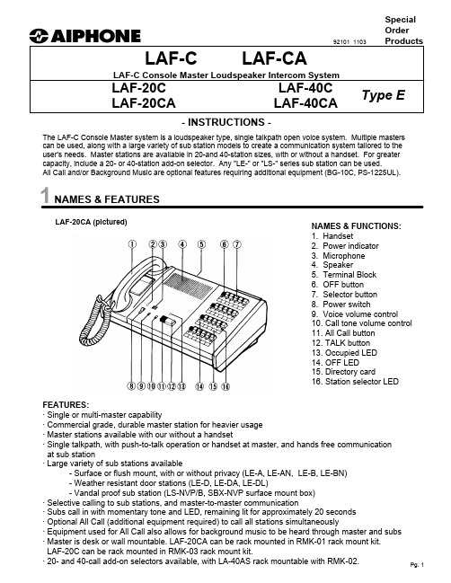
- INSTRUCTIONS -The LAF-C Console Master system is a loudspeaker type, single talkpath open voice system. Multiple masters can be used, along with a large variety of sub station models to create a communication system tailored to the user's needs. Master stations are available in 20-and 40-station sizes, with or without a handset. For greater capacity, include a 20- or 40-station add-on selector. Any "LE-" or "LS-" series sub station can be used.All Call and/or Background Music are optional features requiring additional equipment (BG-10C, PS-1225UL).LAF-C LAF-CALAF-C Console Master Loudspeaker Intercom SystemLAF-20C LAF-40C LAF-20CALAF-40CASpecial Order Products1 NAMES & FEATURESFEATURES:· Single or multi-master capability· Commercial grade, durable master station for heavier usage · Master stations available with our without a handset· Single talkpath, with push-to-talk operation or handset at master, and hands free communication at sub station· Large variety of sub stations available- Surface or flush mount, with or without privacy (LE-A, LE-AN, LE-B, LE-BN)- Weather resistant door stations (LE-D, LE-DA, LE-DL)- Vandal proof sub station (LS-NVP/B, SBX-NVP surface mount box)· Selective calling to sub stations, and master-to-master communication· Subs call in with momentary tone and LED, remaining lit for approximately 20 seconds · Optional All Call (additional equipment required) to call all stations simultaneously· Equipment used for All Call also allows for background music to be heard through master and subs · Master is desk or wall mountable. LAF-20CA can be rack mounted in RMK-01 rack mount kit. LAF-20C can be rack mounted in RMK-03 rack mount kit.NAMES & FUNCTIONS:1. Handset2. Power indicator3. Microphone4. Speaker5. Terminal Block6. OFF button7. Selector button8. Power switch9. Voice volume control 10. Call tone volume control 11. All Call button 12. TALK button 13. Occupied LED 14. OFF LED15. Directory card16. Station selector LEDLAF-20CA (pictured)Type E92101 1103Individual Components for System:LAF-20C 20-call console-style master station LAF-20CA 20-call console-style master station with handset LAF-40C 40-call console-style master station LAF-40CA 40-call console-style master station with handset LA-20AS 20-call Add-on Selector LA-40AS 40-call Add-on Selector PS-1225UL 12V DC, 2.5A Power Supply. One per system, orone per BG-10C when All Call/Music is included (also powers intercom system)LE-series Any sub station with "LE-" prefix LS-NVP/B Vandal proof sub station for LAF-C/CA system SBX-NVP Surface mount box for LS-NVP SA-1Surge Arrestor (1 per 2 wires being protected)LAF-C TERMINAL DEFINITIONS:+Positive 12V DC -Negative 1~40Station number, establishes communication to other master or sub C "CALL", for receiving a call from another masterE Common communicationR Control for Occupied light("R" is grounded when system is occupied)Y All Call override control of station in use during All Call(9V DC when system is in All Call mode)P1All Call activation control (10V DC when All Call is activated)P2, P3 Audio output for All Call initiation (Voice transmit from master initiating All Call)X1~X8Connection for add-on selector (Type E)Remove X2/X3 jumper when add-on selector is used.WIRING & INSTALLATION:Before Installation:· Make sure you have the proper power supply(ies) and all necessary and compatible equipment for the system.· All Call and/or background music are optional features which require additional equipment. See notes below.· Lay out your system in advance, assigning station numbers for all sub station locations.· Surge protection for the intercom equipment is strongly recommended. Add SA-1 surge arrestors for the power supply, plus one per two wires connected to the master station. See diagram on page 3.Wire:· Shielded wire is recommended. Use the proper gauge for the distance being run.· Wiring between masters must be a multi-conductor cable. If more than one cable is used to connect masters, the "E", "C", and number terminal wires must be in the same jacketed cable. If necessary, run multiple "E"wires, one in each cable.Wiring Method:· Run intercom cables at least 20" away from all AC wiring, fluorescent lights, dimmer switches, and other electrical or electronic devices. Wiring can cross AC wires at 90 degrees.· Sub stations may be homerun to the nearest master station, or daisy-chained. If daisy-chained, include 2 common wires plus one individual wire per station on the run.· In a SINGLE MASTER SYSTEM ONLY: Subs can be wired with 2 conductors homerun. Jumpers between "E" and "-" must be attached on all subs and at the master.Intercom Locations:· Do not install intercoms near dimmer or light switches, or other electrical wall devices.· To prevent feedback, do not place sub stations back-to-back on a common wall.All Call and Background Music:· The BG-10C adaptor and PS-1225UL power supply are required for each group of 11 stations to receive All Call and music. This equipment should be installed in an equipment room or in a cabinet. Capacitors (NP-25V) are required for each sub station on the system. See wiring diagram on page 5 for installation information.2 COMPONENTS & WIRINGX4X3X2X1E E E E -+X8X7X6X5P3P2P1Y RC1234567891011121314151617181920LAF-20C/CA terminal blockJUMPERS:In multi-master system, remove E/- jumper at master andsub stations.When add-on selector is included, remove X2/X3 jumper.INTERNAL CONTROLS:CALL TONE VOL.: SW4, located inside unit under selectswitch panel, controls call tone volume. Level is set at max. from factory. Change position to lower call tonevolume.VOX. SENSITIVITY: Potentiometer is located inside unit behind handset. Adjust for sensitivity of VOX circuit.SW5 SWITCH: In "A" position from factory, which mutescall tone from sub while system is occupied."B" position allows call tone to be heard while system isoccupied.3a. SINGLE MASTER SYSTEM, NO ALL CALL LAF-20C3c. THREE MASTER STATIONS WITH SUBS WIRED TO DIFFERENT MASTERSLAF-40CA LAF-40CA LAF-40CA3e . S I N G L E M A S T E R S Y S T E M W I T H A L L C A L LL A F -20C A B G -10C #1w i r e d t o "11" a b o v e .4. E a c h B G -10C c a n p r o v i d e m u s i c a n d /o r A l l C a l l t o a s m a n y a s 11 s u b o r m a s t e r s t a t i o n s . I n c l u d e a s m a n y a d a p t o r s a n d p o w e r s u p p l i e s a s n e c e s s a r y t o p r o v i d e e n o u g h o u t p u t s t o t h e s t a t i o n s i n t h e s y s t e m .5. D o n o t c o n n e c t "+" t e r m i n a l b e t w e e n m u l t i p l e B G -10C a d a p t o r s .4 OPERATIONS & SPECIFICATIONSOPERATIONS:* POWER SWITCH MUST BE ON FOR THE SYSTEM TO BE OPERATIONAL.Receiving a call from a sub station:1. Sub station calls in with mono-electronic tone, heard as long as call button at sub is depressed.2. LED light corresponding to calling station will light at master, staying on approximately 20 seconds.3. Depress station button with lit LED.4. Press TALK button to speak, and release to listen. With handset model (LAF-CA), speak to sub stationprivately with voice actuated (VOX) handset. TALK button is also functional on LAF-CA models.5. Press OFF button to the left of the station selector button when the call is concluded.Calling a sub or master station:1. Depress station number of the location you wish to call.2. Press TALK to speak, and release to hear reply, or use handset.3. If you wish to send a pre-announce tone to the called station, press the TALK and ALL CALL buttonssimultaneously. A mono-electronic tone will be heard at the called station.4. Press OFF button to the left of the station selector button when the call is concluded.Receiving a call from another master station:1. When one master calls another master, no station LEDs light up, and the responding master answersback hands free. The calling master uses the TALK button to speak.2. The calling master can use the handset, but the responding master must speak hands free.3. The "occupied lamp" will be on while the initiating master has a station selected.4. The responding master should not press any buttons to respond to another master's call.Initiating an ALL CALL from the master station, and features of the BG-10C:1. Press and hold the black ALL CALL button, then make an announcement.2. To conclude, simply release the button.3. All Call is a one way outgoing announcement only. If a station wishes to respond, they must press their call button, and the master station can then answer the call as described above.4. If background music is included, the music will be heard on the system while it is not occupied. When any master station selects a station to place or answer a call, the music will be muted throughout the entiresystem.5. If a door station is wired to the BG-10C to produce a chime, a 4-stroke chime will be heard through thestations selected to receive the chime (switches under plate on BG-10C). A call from a door station can only be answered by a master station.SPECIFICATIONS:Power Source:12V DC at master. Use one PS-1225UL per system,or one PS-1225UL per BG-10C when All Call is included.Communication Output:800mW at 20 ohms (receive); 500mW at 20 ohms (transmit)Communication:Push-to-talk, release-to-listen (TALK button), or VOX handset at master.Hands free at sub station.Calling:Master to sub or other master: By voice (TALK) or tone (TALK & ALL CALL simult.)Sub to master: Call button on sub activates tone and LED at master,remaining lit for approximately 20 seconds.Wiring: 2 conductors homerun to sub station (1-Master system only), 3-conductor, or loop multi-conductor with 2 common + 1 individual wire per sub station on wire run.Shielded cable is recommended.Single Master Systems without BG-10C:Aiphone #822202, 2 cond. 22AWG; #821802, 2 cond. 18AWGMulti-Master System (Can also be used in a single master system or systems with BG-10C):#822203, 3 cond. 22AWG; #822206, 6 cond. 22AWG.LAF-C to ea. BG-10C: Aiphone #822220, 20 cond. 22AWG.Wiring Distance:650' with 22AWG; 1,600' with 18AWG.Dimensions:LAF-20C: 10-1/4" x 13-1/2" x 5-1/2". LAF-20CA: 10-1/4" x 17-3/4" x 5-1/2"(H x W x D)LAF-40C: 10-1/4" x 19-1/2" x 5-1/2". LAF-40CA: 10-1/4" x 23-1/2" x 5-1/2"LA-20AS: 10-1/4" x 7" x 5-1/2". LA-40AS: 10-1/4" x 12-7/8" x 5-1/2".5 TROUBLESHOOTING GUIDEPROBLEM1. No call tone or LED when sub calls master.2. Call tone works, but no communication, orcommunication works, but no call tone.3. Call tone is too loud or too quiet.4. Master stations cannot call each other.5. LED lights don't light up when calling master-to- master.6. Occupied light is always on.7. When subs call in, multiple LEDs light up.8. All Call doesn't work.9. All call doesn't work, but adaptors are included.10. When All Call is made, all station LEDs light up.11. Feedback is heard between intercom stations in adjacent rooms.12. System has AC hum when listening to another station from a master station.SOLUTION1. Make sure jumper is installed between E & -terminals at the master and all sub stations (in 2-wire configuration).2. Same as #1 in 2-wire system. In 3 wire system, 1 &E are for communication, and 1 & - are for call-in. Check continuity and connection of wires.3. Call tone volume control is located on main PC board under select switch panel (white 3-pos. switch). Level is set to maximum. Move to mid or low position.4. The "C" terminal on the master station means "CALL", and provides master-to-master communication. Make sure the "C" of one master is connected to a designated station # on another master.5. Station LEDs only light when a sub station calls. Responding master answers hands free, therefore not having to select a station.6. Make sure all black OFF buttons on master(s) are off (pressed down). Check "R" wire for short to ground. If occupied light remains lit with "R" wire disconnected from master, internal damage has occured, and the unit must be sent in for repair.7. Make sure station number wires aren't shorted together. Remove all jumpers between E & - in multi-master or 3-wire system. Test master by taking wires off # terminals, then momentarily shorting # terminal to -(neg). If more than one light comes on, internal damage has occured, and the master must be repaired.8. All Call is an optional feature requiring a BG-10C and PS-1225UL for every 10-11 stations in the system. Make sure adaptors are wired properly. See diagram#3e.9. Check connection of P1, P2, P3 terminals between master and BG-10C's. P1 should read at least 10V DC when All Call button is pressed. Voice is carried on P2, P3 wires.10. If single-call sub stations are used, NP-25V capacitors must be installed as shown on diagram #3e.11. Intercom stations should not be mounted back-to-back on a common wall. Separate them by at least two feet, or on separate walls if possible. Adjust voice volume control to eliminate feedback.12. Intercom wiring must be at least 20" away from any AC wiring, fluorescent lights dimmer switches, or other AC devices. Cross at 90 degrees when necessary. If shielded wire was used, tie all shields together and ground at one end to an earth ground. If noise persists, isolate source of noise and separate the intercom station and wiring from the source.6 PRECAUTIONS & WARRANTYCAUTION* Do not connect any AC wires to any terminal on any unit, as fire or unit damage may occur. Connect only specified power source on +, - terminals.* Do not install more or different power sources than specified for the system.* Do not attempt to install or connect wires on LAF-C system while the system's power supply is plugged in.* LAF-C masters and related equipment, unless specified as "weather resistant", are designed for indoor use only.Door stations (LE-D, LE-DA, LE-DL) may be installed outdoors.IMPORTANT* There is no need to disassemble the equipment for installation. Call tone volume and handset vox sensitivity adjustments are inside the master station, and are the only controls to be accessed inside the unit. Do not access the PC boards inside the units unless properly qualified.* Any other manufacturer's products installed with the system (power supply, external signalling device, etc.) are not covered under Aiphone's warranty.* Do not mount LAF-C equipment in the following places, as it may cause the system to malfunction:- High or extreme cold temperature areas: under direct sunlight, near equipment that varies in temperature, in front of air conditioner, inside a refrigerated area, etc.- Places subject to moisture or humidity extremes.- Places subject to environmental conditions, such as dust, oil, chemicals, salt, etc.* LAF-C units are electronic devices, which must not be subjected to water or any other liquid.* Severe weather conditions, such as lightning storms, may cause damage to LAF-C equipment. We recommend that power surge protection be installed to minimize potential component level damage.- Install the SA-1 surge arrestor as shown to protect the power supply from a surge.- Additional SA-1 surge arrestors should be installed on all communication lines (one SA-1 for every two wires connected to master.) See diagram #3a.LAF-C MasterToll Free Technical Support1-800-692-0200TOLL FREE FAX LINE:1-800-832-3765Aiphone Communication Systems 1700 130th Ave. N.E.Bellevue, WA 98005(425) 455-0510Pg. 8LAF-C Instr. Lit #92101。
6.14康海8路串口服务器说明书

8路协议转换器使用说明书目录路协议转换器用户手册 (1)8路协议转换器用户手册前言 ...................................................................................................................................... 1一.前言技术规格 .............................................................................................................................. 1二.技术规格产品功能 ............................................................................................................................ 1三. 产品功能硬件安装 .............................................................................................................................. 3四.硬件安装路协议转换器安装指南 (6)8路协议转换器安装指南概述 ..................................................................................................................................... 6一概述二.产品简介: .......................................................................................................................... 6三.性能参数 ........................................................................................................................... 6三.性能参数四.连接器和信号 ................................................................................................................... 7四.连接器和信号五.安装及设置 : .................................................................................................................... 7五.安装及设置六.附 录:............................................................................................................................ 21六.附28 路协议转换器线序说明 (28)8路协议转换器线序说明8路协议转换器用户手册一.前言8路协议转换器也叫通讯服务器、访问服务器、异步串口服务器,是一个带有CPU 和嵌入式OS 及完整TCP/IP 协议栈的独立智能设备,主要工作是完成串行数据和网络IP 包之间的数据转换,从而完成终端登陆,扩展串口,将传统的串行设备联网,串行设备互相通信等功能。
PC7413板卡八位八路多功能DA转换说明书
目录一、概述 (2)主要技术参数 (3)二、工作原理 (3)1.工作原理图 (3)2.工作原理简述 (4)3. 调试增益及零点 (6)4. 上电检查 (6)三、使用方法 (7)1. I/O端口地址选择 (7)2. I/O端口地址定义 (7)3.D/A数据格式及控制字 (8)4. 输出接口XS插座定义 (8)5. 输出量程择 (9)6.输出量程调试 (9)四、程序举例 (11)1.初始化程序 (11)2.举例说明 (12)五.维修服务 (12)附录一:编程指导和测试软件说明 (13)1. D/A数据输出 (13)2. DOS下的测试程序功能说明 (13)3. Windows下的测试程序功能说明 (13)4. 所附磁盘文件说明 (14)5.软件I/O端口采集延时 (14)6.Windows下动态库的调用……………………………….14.PC-7413八位八路独立多功能D/A转换8路开关量DI/DO板一、概述PC-7413采用ISA(PC)总线标准,面向工业过程控制而设计的8位8路独立D/A转换输出板,D/A转换芯片采用八片DAC0832,采用多级运算放大器,电压和电流信号同时输出。
用户不需要从外部接入辅助电源。
板上有8路开关量输入,8路开关量输出,输出带锁存,输入输出范围0~5V。
本板可直接插入工业PC或兼容机品牌机中使用。
PC-7413 D/A输出信号是通过板上37芯D型孔头XS1与现场相连的,输出电压有多种量程可供选择,输出量程的改变是由板上跳线器W1~W8决定的。
设计时充分考虑了工业现场的需要,上电时每一路D/A输出自动清零;计算机对输出控制时用户既可选择单通道输出也可选择多通道同时同步输出。
PC-7413 开关量输入输出是通过板上的20芯IDC接头与现场相接的,输入输出电压范围为TTL电平。
输出上电自动清零。
PC-7413端口地址可在100~3FFH之间任选4个I/O地址作为本板的端口地址,出厂时为300~303H。
ASCII代码转换表

ASCII求助编辑ASCII(American Standard Code for Information Interchange,美国信息互换标准代码)是基于拉丁字母的一套电脑编码系统。
它主要用于显示现代英语和其他西欧语言。
它是现今最通用的单字节编码系统,并等同于国际标准ISO/IEC 646。
目录展开编辑本段名称美国信息交换标准代码( American Standard Code for Information Interchange, ASCII ) 编辑本段产生编辑本段常见ASCII码的大小规则0~9<A~Z<a~z1)数字比字母要小。
如“7”<“F”;2)数字0比数字9要小,并按0到9顺序递增。
如“3”<“8” ;3)字母A比字母Z要小,并按A到Z顺序递增。
如“A”<“Z” ;4)同个字母的大写字母比小写字母要小32。
如“A”<“a” 。
记住几个常见字母的ASCII码大小:换行LF为0x0A;回车CR为0x0D;空格为0x20;“0”为0x30;“A”为0x41;“a”为0x61。
另外还有128-255的ASCII字符编辑本段查询ASCII技巧方便查询ASCII码对应的字符:新建一个文本文档,按住ALT+要查询的码值(注意,这里是十进制)松开即可显示出对应字符。
例如:按住ALT+97,则会显示出‘a’。
编辑本段字符集简史6000年前象形文字3000年前字母表1838年到1854年 Samuel F. B. Morse发明了电报,字母表中的每个字符对应于一系列短的和长的脉冲1821年到1824年 Louis Braille发明盲文,6位代码,它把字符、常用字母组合、常用单字和标点进行编码。
一个特殊的escape代码表示后续的字符代码应解释为大写。
一个特殊的shift代码允许后续代码被解释为数字。
1931年 CCITT标准化Telex代码,包括Baudot #2的代码,都是包括字符和数字的5位代码。
8M切换台

[Key DME Wipe Modify] 菜单 ...........................................................................................................II-30 [Audio Channel] 菜单的详细信息............................II-30
4-296-436-61 (2)
多格式小型切换台
使用说明书 (高级设置 第 II 册)
操作本机前,请务必仔细通读这本手册并妥善保管以备今后查阅。
MCS-8M
软件版本 1.00
© 2011 Sony Corporation
目录 (本文档)
第 1 章 概述
简介 ................................................................................. II-5 系统配置示例...................................................................... II-5
语码转换(code-switching)
9
3.1 Markedness theory (标记理论)
Scotton: 语码代表着一组组权利和义务,语码选择既是
手段又是标志,进行无标记选择和有标记选择两个交际 目的. eg: Shopping 姐姐 弟弟 家乡话 普通话 有标记选择 无标记选择
© Copyright 2003 Dr Lubna Alsagoff
18
© Copyright 2003 Dr Lubna Alsagoff
Thank you!
2011级 学科教学
© Copyright 2003 Dr Lubna Alsagoff
19
16
5. References
[1]范琳.语码转换述要[J].青岛海洋大学学报社会科 学版,1998(4). [2]高军,戴炜华.语码转换和社会语言学因素[J].外 国语,2000(6). [3]兰萍.语码转换及其社会意义[J].西南民族学院学 报(哲学社会科学版),2003(5). [4]刘正光.语码转换的语用学研究[J].外语教学, 2000(4).
3
语码(code)是社会语 言学家用来指语言或语 言的任何一种变体 (language variety),是一 个中性词,不带有感情 色彩。
© Copyright 2003 Dr Lubna Alsagoff
1.2 Code-switching (语码转换)
在同一会话中,说双语或多语的人可能时而用这 种语言或变体,时而使用另一种语言或变体,不 断地换来换去……我们称这种现象为语码转换 (Zwicky,1995)。
© Copyright 2003 Dr Lubna Alsagoff
EBCDIC码与ASCII码相互转换VBA
A text file of data from a mainframe computer may be encoded in the EBCDIC character system. This is not directly usable by VBA, which uses the ASCII character encoding system when reading and writing text files.This article provides a function to translate between two character encoding schemes and some helper functions to build the translation table.可能对文本文件的大型机中的数据进行编码,EBCDIC 字符系统中。
这不是直接由 VBA,使用 ASCII 字符编码系统读取和写入文本文件时可用。
本文提供了两个的字符编码方案和一些 helper 函数,生成翻译表之间进行转换的函数。
Notes Regarding Character SetsVBA supports UNICODE, which is a superset of ASCII. Only characters that fall into theASCII range (Chr(0) to Chr(255)) will be translated.The translation tables supplied can be used to translate a string of text from the . EnglishEBCDIC code page (CECP 037) character set to the ISO/ANSI ASCII character set and backagain.The ISO/ANSI ASCII character set is used by Windows, but it is not the same as the IBMPC OEM ASCII character set, although the lower 128 characters are identical.Because there are several variations of both the EBCDIC and ASCII character sets,especially for international use, feel free to add customized translation tables.Here are some notable differences in the ASCII-to-EBCDIC translation for HP, IBM (asdocumented in the IBM 3780 manual), and AT&T:有关字符集的笔记VBA 支持 UNICODE,是 ASCII 的一个超集。
话音编译码器
18
前向自适应(forward adaptation)
• 根据未量化的样本值的均方根值来估算输入信号的电平, 以此来确定量化阶的大小,并对其电平进行编码作为边信 息(side information)传送到接收端
21
差分脉冲编码(DPCM)
• 差分信号d(k)是离散输入信号S(k)和预测器输出的 估算值Se(k-1)之差 • Se(k-1)是对S(k)的预测值,而不是过去样本的实 际值
• 接收端
22
自适应差分脉冲编码调制 (ADPCM)
• ADPCM(adaptive difference pulse code modulation) • 综合了APCM的自适应特性和DPCM系统的差分 特性,是一种性能比较好的波形编码。 • 核心想法::①利用自适应的思想改变量化阶的大 小,即使用小的量化阶(step-size)去编码小的差 值,使用大的量化阶去编码大的差值,②使用过 去的样本值估算下一个输入样本的预测值,使实 际样本值和预测值之间的差值总是最小。
26
• 波形编译码的基本思想
不利用生成话音信号的任何知识而企图产生 一种重构信号,它的波形与原始话音波形尽可能 地一致。
• 最简单的波形编码是脉冲编码调制,
PCM (pulse code modulation) 仅对输入信号进行采样和量化 , 优点:编译码器简单,延迟时间短,音质高。 不足:数据速率比较高,对传输通道的错误比较 敏感。
23
• 接收端的译码器使用与发送端相同的算法,利用传送来的 信号来确定量化器和逆量化器中的量化阶大小,并且用它 来预测下一个接收信号的预测值
迈巴迪音频系统指南说明书
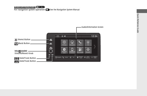
(P 262)Features About Your Audio SystemThe audio system features AM/FM radio and SiriusXM® Radio service*. It can alsoplay USB flash drives, iPod, iPhone and Bluetooth® devices.You can operate the audio system from the buttons and switches on the panel, theremote controls on the steering wheel, or the icons on the touchscreen interface.*1:Models with Display Audio1About Your Audio SystemSiriusXM® Radio* is available on a subscription basisonly. For more information on SiriusXM® Radio*,contact a dealer.2General Information on the Audio SystemP.334SiriusXM® Radio* is available in the United States andCanada, except Hawaii, Alaska, and Puerto Rico.SiriusXM®* is a registered trademark of SiriusXMRadio, Inc.iPod®, iPhone® and iTunes® are trademarks of AppleInc.State or local laws may prohibit the operation ofhandheld electronic devices while operating avehicle.Remote ControlsiPodUSB Flash Drive*2*1uu Audio System u USB Port(s)FeaturesUSB Port(s)■On the front panel ()The USB port (2.5A) is for charging devices, playing audio files and connecting compatible phones with Apple CarPlay or Android Auto.u To prevent any potential issues, be sure to use an Apple MFi Certified Lightning Connector for Apple CarPlay, and for Android Auto, the USB cables should be certified by USB-IF to be compliant with USB 2.0 Standard.■On the front panel ()*The USB port (2.5A) is only for charging devices.u You cannot play music even if you have connected music players to it.1USB Port(s)•Do not leave the iPod or USB flash drive in the vehicle. Direct sunlight and high temperatures may damage it.•We recommend that you use a USB cable if you are attaching a USB flash drive to the USB port.•Do not connect the iPod or USB flash drive using a hub.•Do not use a device such as a card reader or hard disk drive, as the device or your files may be damaged.•We recommend backing up your data before using the device in your vehicle.•Displayed messages may vary depending on the device model and software version.The USB port can supply up to 2.5A of power. It does not output 2.5A unless requested by the device.For amperage details, read the operating manual of the device that needs to be charged.Under certain conditions, a device connected to the port may generate noise to the radio station you arelistening to.USB chargeModels with color audio systemModels with Display Audiouu Audio System u USB Port(s)Features ■On the back of the consolecompartment*The USB ports (2.5A) are only for charging devices.u You cannot play music even if you haveconnected music players to them.uu Audio System u Audio System Theft ProtectionAudio System Theft ProtectionThe audio system is disabled when it is disconnected from the power source, such aswhen the battery is disconnected or goes dead. In certain conditions, the systemmay display a code entry screen. If this occurs, reactivate the audio system.■Reactivating the audio system1.Set the power mode to ON.2.Turn on the audio system.3.Press and hold the VOL/AUDIO (Volume/Power) knob for more than twoseconds.u The audio system is reactivated when the audio control unit establishes aconnection with the vehicle control unit. If the control unit fails to recognizethe audio unit, you must go to a dealer and have the audio unit checked.Featuresuu Audio System u Audio Remote ControlsFeaturesAllow you to operate the audio system while driving. The information is shown on the driver information interface.VOL +/VOL - (Volume) Switch Press Up: To increase the volume.Press Down: To decrease the volume./ (Seek/Skip) Buttons •When listening to the radioPress : To select the next preset radio station.Press : To select the previous preset radio station.Press and hold : To select the next strong station.Press and hold : To select the previous strong station.•When listening to an iPod, USB flash drive, Bluetooth ® Audio, or Smartphone ConnectionPress : To skip to the next song.Press : To go back to the beginning of the current or previous song.•When listening to a USB flash drive Press and hold : To skip to the next folder.Press and hold : To go back to the previous folder./ (Seek/Skip) ButtonsLeft Selector WheelVOL +/VOL - (Volume) Switch。
- 1、下载文档前请自行甄别文档内容的完整性,平台不提供额外的编辑、内容补充、找答案等附加服务。
- 2、"仅部分预览"的文档,不可在线预览部分如存在完整性等问题,可反馈申请退款(可完整预览的文档不适用该条件!)。
- 3、如文档侵犯您的权益,请联系客服反馈,我们会尽快为您处理(人工客服工作时间:9:00-18:30)。
一,前言
FM8PC71AS往下相容於FM8PC71A
可以使用FM8PC71A的燒錄檔案,對FM8PC71AS進行燒錄二,轉CODE說明
打開我司提供的CodeToCode程式
1,請選取”Load File”
2,選定所要轉換的FTC檔
3,按下“開啟舊檔”
4,請點選“Save as” , 此時為要存取FM8PC71AS的FTC檔
5,請指定FM8PC71AS FTC檔的檔案名,不可跟原先FM8PC71A同名6,請點選”存檔”
此時會出現,”Save File ok” , 代表己轉換成功,FM8PC71AS的FTC檔, 會存在,原先FM8PC71A的目錄中
三,燒錄FM8PC71AS
我司目前提供的FM8PC71AS燒錄軟體,為免安裝檔,請直接執行
請在IC型號上,請選取8PC71AS
點取Open File ,選取所以要燒錄的檔案
最後請檢查Config的設定,即可燒錄
四,轉Code 注意事項
1,Timer/Pwm
在Timer/Pwm 中,需注意其設定方法,需先Load Timer 的值
才能對Timer 進行打開,此為點跟fm8pc71a 不同,以下範例說明
此範例為在紅線框的指令中,己經將pwm2cr 的bit2打開,即己打開Timer 功能後 再進行設定Timer 值,此寫法在FM8PC71AS 中不接受,需進行修改
修改完的CODE 為先設定Timer 的值,再將
Timer 打開,即可正常工作
原始的code:
結論:
FM8PC71AS Timer/Pwm:應先load Timer/Pwm 值, 在打開Timer/Pwm 才能工作。
