耶尔智能锁-型号1006操作说明书
ekey home 使用说明书

ekey home zh使用说明书原版使用说明书的译文 - ID 172/494/0/611目录概述 (3)阅读提示 (3)产品责任和责任限定 (3)担保和制造商质保 (3)提示、符号和缩写 (3)安全提示 (4)电流会造成生命危险 (4)防擅自操作的安全性 (4)产品说明 (5)系统概览 (5)供货范围 (5)按规定使用和应用领域 (5)指纹扫描器 (6)控制单元 (8)技术数据 (10)安装和调试 (11)输入安全代码 (12)修改安全代码 (12)设置继电器切换时间 (13)执行测试模式 (14)设置 LED 亮度 (16)设置数字输入端 (17)存入手指 (18)应用 (20)开门 (20)删除用户 (20)展示模式 (21)调出系列号和版本号 (21)将系统恢复出厂设置 (23)软件升级 (23)错误显示和排除 (24)保养 (24)废弃处理 (24)一致性声明 (25)zh│1版权 (25)2│zh概述本说明书是产品的一部分。
请妥善保管。
如需更多关于产品的信息,请联系您的专业经销商。
在以下情况中可能会影响设备的安全运行和功能。
这种情况下,由运营商/用户承担因功能故障而导致的责任:□未按说明书安装、使用、维护和清洁系统设备;□在按规定使用的范围外使用系统设备;□在系统设备上进行未获运营商授权的修改。
本使用说明书没有修改服务。
保留光学和技术修改的权利,不完全排除内容错误、排版和打印错误。
通常参照我们的一般贸易和交货条件(购买产品时的有效版本)。
参见.提示、符号和缩写表示进一步的信息和有用的提示。
表示直接的危险情况,会导致死亡或重伤。
表示可能的财产损失,不会出现人身伤害。
阅读提示产品责任和责任限定担保和制造商质保zh│34│zh符号:1. 逐步的操作指示 参考本说明书的段落参考装配说明书 参考布线平面图□ 无固定顺序的列表,第 1层级显示值 ekey home 指纹扫描器嵌装产品名称 菜单项 菜单项 按键按键缩写和术语:AR arteFAR False Acceptance Rate 错误接受率 FRR False Rejection Rate 错误拒绝率 FS 指纹扫描器 IN integraSE 控制单元指纹图案通过指纹图案获取的生物统计信息安全提示所有ekey home设备均用保护低电压运行。
指纹门锁操作说明书

指纹门锁操作说明书本指纹锁一共可以存储 99 枚指纹,第1 枚指纹为超级指纹,前2~9 枚为管理指纹,后90 枚为普通指纹,其中第1 枚指纹具有添加删除2~99 号指纹的权限,第2~9 枚指纹具有添加删除10~99号指纹的权限。
备注:只有一个功能按键;有两个LED灯,蓝灯添加指纹指示灯,红灯删除指纹指示灯;需要和钥匙配合才能正常使用添加,删除功能.1.1 出厂状态:出厂时指纹库为空,可用备用钥匙开门.1.2 登记指纹:要使用指纹进行开锁,必须首先登记指纹1.2.1 登记第1 枚超级指纹:(指纹库为空时,自动识别第一枚指纹为超级管理员指纹)插入钥匙,开启锁→按上电键→蓝红LED同时闪烁(等待10S,若无输入则自动掉电)→按下要输入的指纹→红灯灭,蓝灯闪时拿开手指→看到蓝红LED灯继续闪烁→再次按下刚才的同一枚指纹→红页脚内容1灯灭,蓝灯闪后拿开手指→蓝灯长亮5S后自动掉电→指纹登记成功并自动记录编号为01(红灯亮表示登记指纹失败,需要重新录入指纹).1.2.2 添加第2~9 枚管理指纹:插入钥匙,开启锁→按上电键→三秒内再按上电键→蜂鸣器嘀一声后,蓝,红LED灯同时闪烁→按下第一枚超级指纹→听到嘀一声后,同时蓝色LED闪烁,表示超级指纹认证通过可以拿开手指(嘀嘀嘀三声表示指纹认证不通过,红色LED闪烁5S后,蓝红LED同时闪烁,给二次认证机会)→10 秒等待,按下要录入的手指,听到嘀一声后拿开手指→蓝色LED急促闪烁→再次听到嘀一声后蓝色LED灯继续闪烁时再次按下手指→听到嘀一声后拿开手指→蓝色LED灯急促闪烁后,蓝红LED同时闪烁(10S内可继续添加管理员指纹)→指纹登记成功/红灯闪烁表示登记指纹失败,需要重新录入指纹(系统自动编号2~9,若存满指纹,再注册时红灯长亮).1.3 添加第10~99 枚指纹:插入钥匙,开启锁→按上电键→三秒内按上电键两次→蜂鸣器嘀一声后,蓝,红LED灯同时闪烁→按下超级指纹或者普通管理员指纹→听到嘀一声后,同时蓝色LED闪烁,表示管理员指纹认证通过可以拿开手指(嘀嘀嘀三声表示指纹认证不通过,红色LED闪烁5S后,蓝红LED同时闪烁,给二次认证机会)→10 秒等待,按下要录入的手指,听到嘀一声后拿开手指→蓝色LED急促闪烁→再次听到嘀一声后蓝色LED灯继续闪烁时再次按下手指→听到嘀一声后拿开手指→蓝色LED灯急促闪烁后,蓝红LED同时闪烁(10S内可继续添加普通指纹)→指纹登记成功/红灯闪烁表示登记指纹失败,需要重新录入指纹(系统自动编号10~99,若存满指纹,再注册时红灯长亮).备注:若比对发现指纹库内有相同的指纹,蜂鸣器发出滴~滴~滴的提示,连续三次,同时蓝色闪烁5S后,蓝红LED再同时闪烁,重新输入新的指纹。
耶鲁智能锁YF1083M 智能电子锁使用者说明书

4. 低功耗模式 系统无操作超过8秒自动进入低功耗模式。
5. 低电量提示 电压低于6.8V以后,每次开锁都会自动提示“电量低,请及时 更换电池”,提示后仍可以开锁200次左右;请务必在开锁次数 归零前更新电池或充电。
外露出门平面 18-20mm
步骤 4 步骤 5
安装后底板: 将硅胶垫套入后底板(没螺柱面), 接着将后底板对准门体孔位安装到 门体室内,再用2颗M5螺丝从底板 插入,固定好锁头盖,用1颗M5螺 丝从底板插入,固定好前板,安装 成整套锁;
图1
安装后面板总成: 将方杆插入锁体方轴,再将后面板总成安装在室内门体上,安 装时锁芯方条、反锁方条、方杆、后底板螺柱必须对准各自相 应孔位,方可锁紧固定后面板总成;
类别
开门钥匙
容量
指纹 识别感应
电特性 工作环境
技术参数
内容
设计指标
管理员
9组(编号001~009) 管理员可以是人脸、指纹、密码或门卡
普通用户
191组(编号010~200) 普通用户可以是人脸、指纹、密码或门卡
机械钥匙
2把
人脸容量
50枚
开门指纹数量
开门密码数量
共200个用户
开门门卡数量
指纹模块认假率
客服电话:400-880-7858
Part of ASSA ABLOY
智能电子锁使用手册
YF 1082R / YF 1083M
* 本产品的功能和设计将会在提升质量的情况下进行更新,恕不另行通知。
目录
产品概述
智能锁使用说明书

智能锁使用说明书使用前请仔细阅读使用说明书,并妥善保管一.技术参数1.技术参数启动方式指纹/密码/卡/机械钥匙指纹传感器半导体供电方式5号碱性电池4节应急电源5V应急电源接口·MiroUSB待机功耗60uA动态功耗小于5A显示OLED键盘背光独立LED指纹容量100枚指纹识别速度小于1S指纹拒真率小于0.01%指纹认假率0.0001%密码输入防窥视密码长度6-12位用户总量300卡类型Mifare 1 高频卡工作温度-30℃ ~ 70℃开锁记录250组初始管理员密码12345623二.用户构成三.功能说明1.用户构成1.功能说明用户类型数量权限管理用户5开锁、进入管理普通开锁用户295开锁1.默认管理员密码:123456,按 + # +管理员密码进入操作系统。
2.系统初始化:初始化系统有两种方式,软件初始化和硬件初始化,软件初始化是进入系统设置后选择初始化菜单,硬件初始化是在后锁面的电池盖里面有个复位按键孔,按住复位按键5秒,屏幕提示初始化系统,按#号键确认初始化。
3.用户容量:用户总量为300个,对应300个用户编号。
每一个用户编号只可以对应一个指纹或者密码或者卡。
编号1~5为管理员用户,6~300为普通开锁用户。
指纹用户量受限于指纹模组。
比如指纹模组的指纹容量为100,则最大指纹用户量为100。
四.操作设置1.按键功能触摸唤醒屏幕指示灯亮起,按 + # 键进入功能菜单验证入口注意:所有的设置和更改都需要进入功能菜单设置。
2号键是上翻,8号键是下翻,#号键是确认, 号键是返回。
***42.设置管理员指纹/密码/智能卡3.删除开锁信息按 + # 号键,进入功能菜单验证入口;输入管理员密码,输入初始密码123456 + # 号键;进入设置界面。
进入设置界面,如图所示;先择录入开锁信息,按#号键确认。
录入管理员信息,按#号键确认;输入密码、指纹、IC 卡;管理员可以设置5位(包括指纹、卡片、密码)编号位001-005。
智能门锁管理软件使用说明

智能门锁管理软件使用手册目录一、概述 (3)二、入门操作 (4)三、主界面 (9)四、操作 (12)4.1 发客人卡 (12)4.2 续住写卡 (13)4.3 客人换房 (14)4.4 补发客人房卡 (15)4.5 客人退房 (15)4.6 查看卡片信息 (16)4.7 发行管理卡片 (17)4.8 挂失卡片 (31)4.9 注销卡片 (32)4.10 读取开门记录 (33)4.11 门锁房号设置(制安装卡) (34)4.12 管理参数设置 (35)4.13 客人预订管理 (38)五、查询 (40)5.1查询各种持卡记录 (40)5.2查询日志记录 (41)六、工具 (42)6.1修改状态 (42)6.2公共信息 (43)6.3万年历 (45)6.4世界时钟 (45)七、系统 (46)7.1重新登录 (46)7.2修改密码 (46)7.3系统参数 (47)7.4操作员设置 (53)7.5数据库维护 (54)一、概述门锁的基本设置:门锁安装完毕,在投入使用前必须使用安装卡对门锁进行系统设置。
设置过程如下:1、用安装卡设置门锁编号;2、用时钟卡设置门锁时间。
注意:安装卡不可对已有系统信息的门锁进行设置,若要重新设置门锁,先用清除卡清除门锁内信息。
卡片的使用和管理:●应急开门卡:可以开所有门,包括反锁。
使用之后,门锁状态始终为开。
此卡一般不用,只在特殊情况时才用此卡。
●总控开门卡:可以开启所有门锁,即使反锁也可以开启。
一般由酒店总经理、客房部经理等管理人员持有,总卡有挂失功能,如果发生丢失,应采用挂失功能补发总卡,并用它将所有的门锁开一遍,这样原来的总卡开门功能将失效,如需恢复已被挂失的总卡的开门功能只需在系统重新做一次总卡即可。
●楼栋开门卡:开某一区域某一栋所有门。
如:***大酒店\***栋。
如果酒店只有一栋楼,没有添加多栋,则不显示该类型。
一般由客房管理人员持有。
●楼层开门卡:开某一区域某一栋某一楼层所有门。
智能锁使用说明书
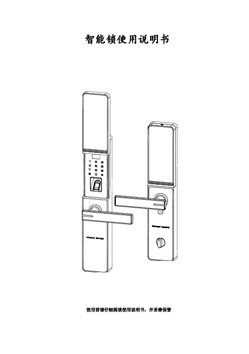
智能锁使用说明书使用前请仔细阅读使用说明书,并妥善保管第一章、概述1.简介感谢购买本公司智能锁系列产品,该系列产品采用了先进的指纹技术、非接触式刷卡、密码和钥匙作为开锁方式,并且具有多种开门模式选择,使用更灵活、更方便、更安全!开门钥匙类型用户类型数量编号范围权限指纹管理员100 0000~0099开门、管理普通用户开门密码管理员100 0000~0099开门、管理普通用户开门IC感应卡管理员100 0000~0099开门、管理普通用户开门电源供应 4.8V-6V(即4或8节干电池)典型静态电流≤90 微安(电池寿命可超过一年)工作电流<280 毫安(驱动能力强)工作温度-20℃~60℃相对湿度20% ~ 95%2.产品优势和特点开锁方式多样化:指纹、密码、刷卡、应急钥匙。
采用半导体指纹头,杜绝假指纹开锁。
有应急钥匙,电池没电或线路故障也能开锁。
应急外接电源,USB接口。
人性化设计,语音提示音量大小可调。
组合开锁,双开模式,使门锁安全更具保障。
具有防旁人窥视密码功能。
具有防撬报警功能。
具有防猫眼功能。
第二章、 产品外观图、尺寸图 1. 产品外观指纹感应卡和密把钥池盖手锁旋钮显示滑池置按键线猫眼定螺钉池定螺钉2. 尺寸图(单位mm )前面板正视图 侧视图 后面板正视图 侧视图3. 适用范围适用场所:高档住宅区、别墅、办公大楼、商务写字楼、星级酒店等。
适合门厚:40-125mm适合门类:木门、铁门及各类复合材质的防盗门。
4.开门方向室内室内左(内推)开门右(内推)开门室内室内左(外拉)开门右(外拉)开门5.更换把手方向6.键盘功说明注意:触摸面板,自动唤醒按键屏指纹锁键盘采用的是12键设计,其具体功能如下:✓ “0-9”号键:为数字键; ✓ “#”号键:进入菜单功能键; ✓ “*”号键:为清除键、返回键、退出键; ✓ “#”号键:在菜单功能状态下按“#”表示确认;注意:超过 30 秒无操作会自动退出系统,请用手背触摸按键屏唤 醒按键屏,才能继续操作(如下图)。
智能门锁说明书
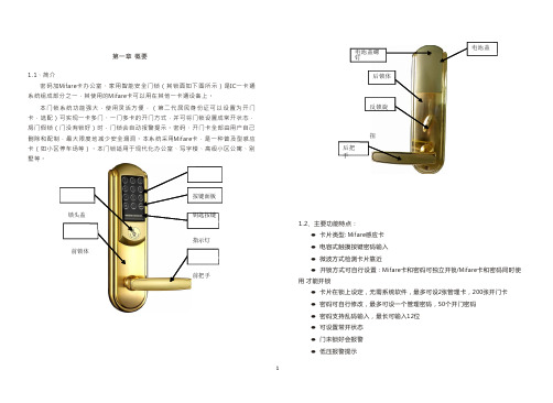
第一章概要电池盖螺钉电池盖1.1、简介密码加Mif a r e卡办公室、家用智能安全门锁(其锁面如下图所示)是I C一卡通系统组成部分之一,其使用的M if a r e卡可以用在其他一卡通设备上。
本门锁系统功能强大,使用灵活方便,(第二代居民身份证可以设置为开门卡,选配)可实现一卡多门、一门多卡的开门方式,并可将门锁设置成常开状态,房门假锁(门没有锁好)时,门锁会自动报警提示。
密码、开门卡全部由用户自己删除和配制,最大限度地减少安全漏洞。
本系统采用M i f a r e卡,是一种普及型感应卡(如小区停车场等)。
本门锁适用于现代化办公室、写字楼、高级小区公寓、别墅等。
后把手后锁体反锁旋扭锁头盖按键面板钥匙按键1.2、主要功能特点:前锁体指示灯前把手●卡片类型: M i f a r e感应卡●电容式触摸按键密码输入●微波方式检测卡片靠近●开锁方式可自行设置:M i f a r e卡和密码可独立开锁/M i f a r e卡和密码同时使用才能开锁●卡片在锁上设定,无需系统软件,最多可设2张管理卡,200张开门卡●密码可自行修改,最多可设一个管理密码,50个开门密码●密码支持乱码输入,最长可输入12位●可设置常开状态●门未锁好会报警●低压报警提示●电池供电,可外接应急电源1.3、主要技术指标●工作电压: 6.0V(4节5号碱性电池)●静态功耗: <50uA●动态功耗: <200mA●电池寿命: 12个月以上●低电压提示: 4.8V●读卡距离: <30mm●工作温度: -25℃-70℃●工作湿度: ≤80%●控制板尺寸: 40mmx60mm●按键板尺寸:50mm x90mm1.4、开门方式M i f a r e卡密码办公室、家用门锁系统有以下两种开门模式:⑴、独立式:单独使用M i f a r e卡或密码可以开门。
⑵、组合式:M i f a r e卡和密码同时使用才可以开门。
注:1.本系统的门锁出厂初始化后的管理密码为12345678,开门模式为独立式。
智能门锁N100 Zigbee版 使用说明书及三包凭证

HomeKit设置代码HomeKit Setting CodeКод установки HomeKit0109智能门锁N100 Zigbee版 使用说明书及三包凭证Smart Door Lock N100 User ManualУмный Дверной Замок N100: Руководство по эксплуатации产品介绍远程接收异常报警、远程查看开锁记录、智能联动、离家模式等相关功能,需搭配具备网关功能的设备使用。
*智能门锁N100是一款集指纹、密码、NFC、钥匙、HomeKit等多种开锁方式的智能门锁。
具备门锁状态检测,低电量提醒,撬锁报警,防猫眼开锁和指纹密码试错报警等多种功能,同时具有一键离家模式,可实现多设备智能联动。
闪烁:白色呼吸:红色闪烁:应急供电口按压盖板1智能门锁N100 使用说明书及三包凭证提示:门锁安装使用准备请务必聘请专业人员进行安装。
若所购套餐中包含上门安装服务,请扫描下方二维码预约安装服务或咨询客服。
扫码预约安装服务,或了解更多产品信息提示:普通电池长期使用时,1请打开电池盖,注意:重置成功后用户为空,2长按重置键5秒,扫描二维码,或在应用商店搜索“Aqara Home App”下载并安装;打开App首页,在页面右上角点击“+”,根据App提示方式添加设备。
**1连接Aqara Home App2添加用户提示:未添加用户状态下,门锁无法正常上锁。
进入门锁设备页面,按照App提示添加首个用户(默认为管理员)。
3HomeKit连接(针对iOS用户)使用准备提示:门锁添加成功后,将自动尝试连接账号下的网关设备,无需配置。
门锁的蓝牙通讯有效距离为10m,墙壁等障碍物可能影响蓝牙通讯距离。
打开Apple “家庭”App,点击页面右上角“+”,选择“添加配件”;根据提示扫描或手动输入门锁后盖或本手册封面的HomeKit设置代码(请妥善保存),根据提示完成添加操作。
SDC QuietDuo LR100系列电动门锁后系统使用指南说明书
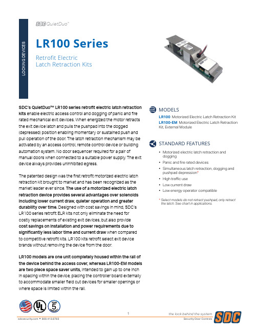
SDC’s QuietDuo™ LR100 series retrofit electric latch retraction kits enable electric access control and dogging of panic and fire rated mechanical exit devices. When energized the motor retracts the exit device latch and pulls the pushpad into the dogged(depressed) position enabling momentary or sustained push and pull operation of the door. The latch retraction mechanism may be activated by an access control, remote control device or building automation system. No door sequencer required for a pair ofmanual doors when connected to a suitable power supply. The exit device always provides uninhibited egress.The patented design was the first retrofit motorized electric latch retraction kit brought to market and has been recognized as the market leader ever since. The use of a motorized electric latch retraction device provides several advantages over solenoids including lower current draw, quieter operation and greater durability over time. Designed with cost savings in mind, SDC’s LR100 series retrofit ELR kits not only eliminate the need for costly replacements of existing exit devices, but also provide cost savings on installation and power requirements due to significantly less labor time and current draw when compared to competitive retrofit kits. LR100 kits retrofit select exit device brands without removing the device from the door.LR100 models are one unit completely housed within the rail of the device behind the access cover, whereas LR100-EM models are two piece space saver units, intended to gain up to one inch in spacing within the device, placing the controller board externally to accommodate smaller field cut devices for smaller openings or where space is limited within the rail.LR100 SeriesRetrofit Electric Latch Retraction KitsLR100 Motorized Electric Latch Retraction KitLR100-EM Motorized Electric Latch Retraction Kit, External ModuleMODELS• Motorized electric latch retraction and dogging • Panic and fire rated devices • Simultaneous latch retraction, dogging and pushpad depression *• High traffic use• Low current draw• Low energy operator compatibleSTANDARD FEATURESQuietDuo* S elect models do not retract pushpad, only retract the latch. See chart in applications.the kit at SDC’s factory. Simply send the mechanical exit device install and factory installed LR100 kits.* Models do not retract pushpad, only retract the latch.Continued on next page. ** Models require a higher 1 Amp inrush current draw.Rim SVRCVRMortisethe kit at SDC’s factory. Simply send the mechanical exit deviceinstall and factory installed LR100 kits.* For Von Duprin 22 models manufactured in 2021 or earlier.SPECIFICATIONSLR100LR100-EMType Retrofit ELR Kit Retrofit ELR Kit, External Module Input24 VDC ± 10%24 VDC ± 10%Current Draw700 mA Inrush*200 mA Continuous700 mA Inrush*200 mA ContinuousLatch Retraction Motorized Motorized* LR100FA, LR100FC and LR100JA models require a higher 1 Amp inrush.LR100 SeriesUL 10C Positive Pressure Fire T ests ULC-S104 Standard Method for Fire T ests of Door AssembliesANSI/BHMA A156.3 Grade 1FOLLOW STEPS FOR ORDERINGDesignates optional stepHOW TO ORDERUL 10C Positive Pressure Fire T ests ULC-S104 Standard Method for Fire T ests of Door AssembliesANSI/BHMA A156.3 Grade 1FOLLOW STEPS FOR ORDERINGDesignates optional stepHOW TO ORDERRELATED PRODUCTSRETROFIT MONITORING KITSIn addition to retrofit motorized electric latch retraction kits, SDC also offers a variety of retrofit monitoring kits for field installation. Request-to-exit (REX) monitoring kits can be used to monitor the pushpad/dogged status on an exit device. The table below outlines exit device compability and part numbers for bothrequest-to-exit (REX) and latch status (LS) monitoring kits.7200Yale6100ED---------------LRY61R-----* The Pamex LRPA1RL kit is both request-to-exit (REX) and latch status (LS).** Available for 33A/35A rim devices only.COMPONENT CONSIDERATIONSLOW ENERGY OPERATORSSDC’s low energy swing door operators are designed for applications requiring ADA compliance, userconvenience and touchless solutions. The state-of-the-art microprocessor-based operator is self-tuning and self-learning while offering non-handed operation, full mechanical stops, door sequencing and a variety of interface options for sensors, push-plates, fire alarms and electrified locks. A built-in 1 Amp power supply allows users to power electric latch retraction directly from the operator.CLICK TO VIEWPUSH PLATES & PANELSSDC’s push plates and panels combined with SDC’soperator s , bollards and locking devices allow for complete access and egress solutions for ADA compliant applications. Included are round and square push plates, as well as wall mount and full-size push panels. All types can be wireless or hardwired, bollard or wall mounted. ADA compliant solutions work seamlessly with low energy swing door operators like Auto EntryControl™.CLICK TO VIEWKEYPADS & READERSSDC has a variety of digital keypad and proximity card access control system equipment to meet any need. SDC’s keypads and readers are engineered to provide real-world door control of a single opening up to 100 doors, such as indoor, outdoor and PC-based systems, while ensuring fire and life safety code compliance along with superior expandability and flexibility in authorization identification, authentication, access approval and accountability of entities through login credentials.CLICK TO VIEWPOWER CONTROLLERSSDC access control power supplies have been developed specifically to support access controls and electric locking hardware. They are UL listed and provide filtered and regulated linear DC power, with optional control logic, component interface, alarm interface and battery back-up to meet the requirements of single and multiple access-controlled openings. The circuitry design is ideal for the inductive loads generated by access control hardware for high performance and longevity.CLICK TO VIEWPOWER TRANSFER DEVICESElectrified power transfer hinges (PTH Series), loops (PT Series) and mortise devices (PTM Series) provide both surface and concealed methods for running wires from the frame to transfer power and monitoring signals to doors equipped with electric locks and exit devices. Wireless power transfer devices (WPT Series) wirelessly transfer power and monitor latch bolt status, REX or data signals to electrified locks and latches.CLICK TO VIEWDOOR CONTROLS & BACKUP BATTERIESSDC’s door control relay modules ensure compatibility of access hardware components and simplify systeminstallation and troubleshooting. Different modules may be specified for one power supply. The isolated relay design allows trigger signals over small gauge cable runs of 22 gauge wire up to 1,000 feet from the trigger device to the module. SDC’s engineered system design services areavailable when you purchase SDC locks, control modules and power controllers for your door opening applications.CLICK TO VIEW。
耶魯數位電子密碼鎖 使用說明書说明书

YDM 3168-FVer. PMU-0904-01※The functions and design of this product can be changed without notice for quality improvement.※Chinese manual is from 33 page. (中文說明書從33頁起)User ManualKeep this manual safe for future reference請妥善保管此說明書及保固卡,以便於日後需要 貼心提醒:請使用原廠提供之RFID卡片、RFID貼紙、RFID手環來開啟您的門鎖,因安全上的疑慮,不建議使用其他格式的感應扣。
33請仔細閱讀以下的安全提示以避免意外發生、財物損失或你的不便,也請教導您的小孩正確操作此產品。
並將此產品說明書妥善保管以便不時之需。
重要的安全提醒:本公司產品商標、名稱、設計、著作權、專利包含產品本身及說明書之權利,均屬於製造商所有。
未經授權不得翻印或複產品各項名稱40規格表391.卡片登記2.密碼登記3.從外部上鎖4.從外部開啟5.從內部上鎖6.從內部開啟7.開啟/關閉安全把手8.自動 /手動上鎖模式9.強制上鎖模式10.入侵 / 破壞 警報11.3分鐘自動鎖死功能12.音量控制13.電池使用及更換方法14.顯示操作狀態(觸控面板)42444546484849515253545556571.緊急電源供給2.遺失卡片3.產品故障4.緊急備用鑰匙使用方法616262631.網路盒2.遙控器585964使用說明注意事項進階模式選配產品安全小幫手安全小幫手安全小幫手安全小幫手虛位密碼適合在密碼被他人窺視時使用。
Mighty Mule 自动门开关操作说明书

When a VEHICLE SENSOR is in use, the automatic gate opener could be activated by a child on a bicycle, tricycle or other metal play equipment. This product is not recom-mended for applications exposed to children.WARNINGThank You ...for purchasing the hands free VEHICLE SENSOR. This product requires no maintenance and will give you years of enjoyment by providing hands free operation of your gate. Gates That Open, LLC, has been designing and manufacturing reliable, high quality products since 1987. Our corporate headquarters and state of the art manufacturing facility is located in Tallahassee, Florida. One of our highest priorities is to provide outstanding technical service to our customers. Therefore, if you have any questions or require any technical assistance, visit or call our toll free line 800-543-1236 for technical support.The VEHICLE SENSOR you have purchased is designed with some of the most advanced technology available. In layman’s terms, the sensor detects a change in the earths magnetic field caused by a mass of metal in motion and automatically opens your gate. The range adjustment potentiometer (POT) that connects to the control box provides you with the ability to increase or decrease the sensor’s sensitivity range.If a metal object is placed directly above the sensor (with little motion) it may cause the sensor to activate, thus opening your gate. For this reason we do not recommend the VEHICLE SENSOR in environments exposed to children.Prior to installing your Sensor please read the manual thoroughly. There are important safety recommendations of which you should be aware. This product, and any accessory you purchase, should only be installed on a gate opener that meets the current safety standard (UL325). If you have a gate opener that is not listed with the current standards, please contact the GTO sales department at 800-543-4283 or 850-575-0176 for consultation on a gate opener that can meet your specific needs.Joe Kelley,President of Gates That Open, LLCContentsBefore You Start ----------------------------------------------------------------------page 1Terms and Definitions: -----------------------------------------------------------page 1How the VEHICLE SENSOR works: ------------------------------------------page 1How the Vehicle SENSOR’s RANGE ADJUSTMENT works: ------------page 1Placement of the SENSOR: -----------------------------------------------------page 1Installation Overview: ------------------------------------------------------------page 2Installing the VEHICLE SENSOR -----------------------------------------------page 3Determining SENSOR Location: -----------------------------------------------page 3Installing the WIRE CLAMP: ---------------------------------------------------page 3Wiring the SENSOR to the Mighty Mule Gate Opener: ---------------------page 4Accessory Terminal Connection ------------------------------------------------page 4Connecting the Range Adjustment Control Board: --------------------------page 5Power Supply Connection: ------------------------------------------------------page 5Powering up the SENSOR: -----------------------------------------------------page 6Adjusting the Range: ------------------------------------------------------------page 6Safety Precautions: ---------------------------------------------------------------page 6Installation on other Brand Gate Openers--------------------------------------page 7Technical Specifications -------------------------------------------------------------page 8Troubleshooting-----------------------------------------------------------------------page 8Other GTO Products ----------------------------------------------------------------page 9This product and any accessory you purchase should only be installed on a gateopener that meets the current safety standard, UL325, 4th Edition. If you havea gate opener that is not listed with the current standard please contact the GTOsales department for consultation on a gate opener that can meet your specificneeds.GTO Limited One Year Warranty:GTO gate openers and accessories are warranted by the manufacturer against defects in materials and manufacturer workmanship for a period of one (1) year from date of purchase, provided the recommended installation procedures have been followed.In the case of product failure due to defective material or manufacturer workmanship within the one (1) year warranty period, the product will be repaired or replaced (at the manufacturer’s option) at no charge to the customer, if returned freight prepaid to GTO, 3121 Hartsfield Road, Tallahassee, Florida, USA 32303. IMPORTANT: Call (800) 543-1236 for a Return Goods Authorization (RGA) number before returning accessory to factory. Products received at the factory without an RGA number will not be accepted. Replacement or repaired parts are covered by this warranty for the remainder of the one (1) year warranty period or six (6) months, whichever is greater. GTO will pay the shipping charges (equal to United Parcel Service GROUND rate) for return to the owner of items repaired under warranty.The manufacturer will not be responsible for any charges or damages incurred in the removal of the defective parts for repair, or for the reinstallation of those parts after repair. This warranty shall be considered void if damage to the product(s) was due to improper installation or use, connection to an improper power source, or if damage was caused by electrical power surge or lightning, wind, fire, flood, insects or other natural agent.After the one (1) year warranty period, GTO will make any necessary repairs for a nominal fee. Call GTO at (800) 543-1236 for more information. This warranty gives you specific legal rights, and you may also have other rights which may vary from state to state. This warranty is in lieu of all other warranties, expressed or implied. NOTE: Verification of the warranty period requires copies of receipts or other proof of purchase. Please retain these records.Before You Start ...Please read the instructions completely before you begin the installation. Terms and Definitions:• METAL OBJECT: anything that is made of iron-based metal, from a child’s toy to a car or truck.• SENSOR: the magnetic device inside the waterproof tube that detects METAL OBJECTS in motion.• MAGNETIC FIELD: an area around the SENSOR where metal in motion can be detected.• MAGNETIC DISTURBANCE: a change in the MAGNETIC FIELD which lets the SENSOR know that it needs to send a signal to the gate opener to open the gate.• RANGE: the distance from the SENSOR in which a MAGNETIC DISTURBANCE can be detected in the MAGNETIC FIELD.• RANGE ADJUSTMENT: the RANGE is adjustable from a 3 to 12 foot* radius by tuning the ADJUSTMENT POTENTIOMETER (POT) on the RANGE ADJUSTMENT CONTROL BOARD (shown on page 5). Within this RANGE, the closer you get to the SENSOR, the less metal and motion an object needs to cause a DIS-TURBANCE in the MAGNETIC FIELD.CAUTION This principle explains why a child’s tricycle, bicycle and other metal objects moving close to the SENSOR may have the same DISTURBANCE as a car or truck at a greater distance, and can cause the gate to open.• WIRE CLAMP: a device which provides a secure and weatherproof opening for the cable from the SENSOR to be brought into a control box (see Parts Identification on cover).• DOUBLE SPADE CONNECTOR: a wire connector which allows the connection of two wires to be connect-ed to a single terminal (see Parts Identification on cover).How the VEHICLE SENSOR works:• When a metal object such as a car, truck or motorcycle in motion disturbs the MAGNETIC FIELD around the SENSOR, a signal is sent to the automatic gate opener’s control board, signaling it to open the gate.• The metal object must be in motion to disturb the MAGNETIC FIELD, thus activating the gate opener.How the VEHICLE SENSOR’s RANGE ADJUSTMENT works:• The RANGE distance can be adjusted from a 3 to 12 foot* radius from the SENSOR.• The potentiometer varies the sensitivity range of the SENSOR to avoid unwanted moving metal objects from activating the gate opener, such as: other moving gates; metal play equipment; garage doors; other vehicular traffic; etc.• With the RANGE adjusted to the maximum of 12 feet*, a large metal object moving slowly will be detected12 feet* from the SENSOR, while a small metal object moving slowly might not be detected at the samedistance. As you move closer toward the SENSOR, the small moving metal object will at some point cause a DISTURBANCE in the MAGNETIC FIELD and activate the gate opener.Placement of the SENSOR:•The SENSOR comes with 50 feet of cable. A typi-cal installation will require about 5 feet of cable to come from the ground up and into the control box for connection to the power supply and control board. Check your specific installation for exact dimensions.•From the point on the ground where you will run the Sensor cable into the control box, lay the cable out on a path as far as you can from the control box. The SENSOR should be no more than 2 feet from the edge of the driveway and no closer than 25 feet from the end of the open gate.•The SENSOR’s RANGE can be adjusted to a maximum of 12 feet*. The movement of a gate in the open position could cause a DISTURBANCE in the MAGNETIC FIELD of the SENSOR if it comes within the RANGE of the SENSOR. Make sure the end of the open gate is a minimum of 25 feet from the SENSOR. If you have a situation where the SENSOR has to be buried closer than 25 feet you will need to adjust the RANGE of the SENSOR to compensate for the closeness.•The SENSOR must be buried 12” in soil to prevent direct sunlight from causing overheating. This also prevents large animals from activating the sensor due to physical vibrations.For Optimum Performance:• Locate the SENSOR as far as possible away from power transformers, power lines, underground gas line, and telephone lines.• Locate the SENSOR away from general moving traffic to prevent unwanted activation. Remember that the SENSOR detects MAGNETIC DISTURBANCES caused by a vehicle’s mass and velocity.• It is recommended that you run the Sensor cable inside PVC conduit.• Do not run Sensor cable in conduit with other wires such as AC power or other control wires.• The Sensor cable CANNOT be spliced. If you need more wire, contact the GTO Sales Department at 1-800-543-GATE (4283).Installation Overview :•underground to the control box. Connect the SENSOR wires and the RANGE ADJUSTMENT CONTROL BOARD to the gate opener control board and power supply. Adjust the RANGE if necessary. Finally, place the WARNING signs on the gate. That’s it!Step 1: Determine the optimum location for the VEHICLE SENSOR using the information found in “Placement of the SENSOR” on page 2. Then dig a hole approximately 12 inches deep and 24 inches long within 2 feet and parallel to the edge of the driveway. Next, dig a trench approximately 12 inches deep from this hole to a spot un-der the gate opener control box to run the cable from the SENSOR to the control board.Keep the SENSOR and the cable uncovered at this time, but out of direct sunlight.We recommend that the cable be run in PVC conduit to the control box to prevent damage to the cable from lawn mowers, weed eaters and grazing animals.Step 4: Unscrew and remove the lock nut from the WIRE CLAMP hub (included with hardware ). From the outside of the control box, insert the WIRE CLAMP hub and sealing nut (see illustration right ) into the new WIRE CLAMP hole . Finger tighten the lock nut onto Installing the WIRE CLAMP: The WIRE CLAMP (includ-ed) is used to secure the sensor cable where it enters the control box to prevent it from being accidently pulled out.Step 2: If you are installing the SENSOR on a Mighty MuleFM700, FM500 and the FM502 gate openers, use a screwdriver or steel punch to carefully remove the thin plastic knockout disk (see illustra-tions at right ) at the bottom of the control box. If you have a FM702 dual gate opener system, drill a 7/8” diameter hole at the bottom of the control box and install the WIRE CLAMP.Step 3: Use a sharp knife or deburring tool to clean the rough edges from the hole.board!Determining SENSOR Location:IMPORTANT: Clear an area 20 feet in all directions of metal tools, toys and automobiles,to prevent magnetic disturbance during testing and installation.Installing the Vehicle Sensor ...Mighty Mule FM500 & FM502IMPORTANT: TURN OFF the power and disconnect thebattery wires b efore you begin to connect the SENSOR wires to anygate opener.Step 5: Run the cable from the SENSOR through a WIRE CLAMP into the control box. Pull about 8 - 10 inches of cable into the control box to reach the ACCESSORY TERMINAL BLOCK and BATTERY TERMINALS in the control box. Now tighten the WIRE CLAMP nut to secure the cable in the WIRE CLAMP.Step 6: Strip about 3/8 of an inch of insulation from the YELLOW, BLACK, RED and BLUE wires in the SENSOR CABLE.Connecting the Range Adjustment Control Board:Step 9: Connect the YELLOW wire from the SENSOR CABLE to the YELLOW wire from the Range Adjustment control board using one of the WIRE NUTS provided.Step 10: Connect the BLACK wire from the Range Adjustment control board to the BLACK BATTERY CONNECTOR wire (provided), along with the SHIELD wire from the SENSOR CABLE (see Step 13 below).Step 14: Connect these wires to the DOUBLE SPADE CONNECTORS as shown.IMPORTANT: Be sure to connect both RED leads to the same DOUBLE SPADE CONNECTOR and bothAdjusting the Range:Step 16:Safety Precautions:Step 17: Place the W ARNING SIGNS on both sides of the gate using Ty-wraps included.Powering Up the SENSOR:NOTE: If you have other accessories connected to yourbattery with double spade connectors you may need to connect a double spade connector to a double spade connector in order to connect all the acces-sories.For Installation on Other Brand Gate Openers ...If you are using the VEHICLE SENSOR on any other automatic gate opener brand, use the informa-tion below for wiring the system. If you do not understand the instructions below, please call GTO’s Technical Support at 1-800-543-1236.Typical Gate Wiring Connection:• Reference Leads:o RED => Input V oltage (+)o SHIELD => Ground/Common (–)o BLACK => Relay’s Commono BLUE => Relay’s Normally Openo YELLOW => Remote SENSOR [Range adjustment potentiometer (POT)]• Terminology Definitions:o ‘FREE EXIT/ENTRY’ is defined as input terminals (2) that upon activation (momentarily connected together) will cause the gate to run in the open direction only. Note: In most gate openers, one of the two terminals is the ‘COM-MON/GND’.• Power supply connection:o DC power supply: (11-36 Vdc)ß Connect the positive (+) lead of the power supply to the RED wire.ß Connect the negative (-) lead of the power supply to the SHIELD wire.o AC power supply: (8-26 Vac)ß Connect the power supply to the RED & SHIELD wires. There is no polarity for AC power supply.• Relay output connection:o Connect the BLUE wire from the SENSOR to the ‘FREE EXIT/ENTRY’ of the gate opener.o Connect the BLACK wire from the SENSOR to the ‘COMMON/GND’ of the gate opener.• Range (POT) board connection:o Connect the YELLOW wire from the SENSOR to the YELLOW wire from the Range Adjustment Board.o Connect the BLACK wire from the Range Adjustment Board to a negative input voltage.o Turn the POT clockwise to increase range.o Turn the POT counter-clockwise to decrease range.TECHNICAL SPECIFICATIONS:• Power supply: 8-26 Vac/dc.• Current consumption: 1.5 mA typical.• Relay rating: Latching relay.Nominal switching capacity (resistive load) 1 Amp 30 Vdc, 0.5 Amp 125 VacMax. switching power (resistive load) 30 Watt, 62.5 V AMax. switching voltage 110 Vdc, 125 VacMax. switching current 1 Amp• Relay Trip Time: 2 seconds.• Operating Temperature: -25°F (-14°C) to 125°F (69°C).• Dimensions: 1-3/4” (44.5 mm) diameter x 16.5” (42 cm) long.• Adjustable range: 3 -12 feet typical installation.• Very low power consumption, ideal for battery application.Troubleshooting: Make sure all connections are correct.If the SENSOR is not working:1. Make sure the Range Adjustment is set at maximum range.2. Disconnect the power (battery) to the SENSOR.3. Reconnect the power to the SENSOR and make sure that no metal object or vehicle is movingaround the SENSOR for 60 seconds while it is calibrating.4. Test the SENSOR to verify that it is working properly.5. Check that push/pull DIP switches on Control Board are set correctly.Key Chain Two Button Transmitter (FM134)The Key Chain Mini Transmitter is a miniature version of the Mighty Mule entry transmitter and has the same adjustable code settings. Used for remote control of multiple separate gate operators, and/or garage door operator(s). (battery included)Automatic Gate Lock (FM143)A MUST for securing the gate against forced entry or exit. Solenoid driven,plated steel bolt lock with a zinc plated steel housing. Used with Mighty Mulesystems for maximum stability and security. Comes with a keyed manual release.Recommended for gates over 8 ft. (2.4m) long. Ideal for animal enclosures or high wind areas. (Not compatible with FM250, MM-SL1000B/MM-SL2000B)5 Watt Solar Panel (FM121)If your gate application is far away from an AC power outlet, or greater than 1,000 ft (304.8m), you can choose to power your Mighty Mule gate operator system with these high output Mighty Mule solar panels. Each solar panel comes with tubular steel support, mounting clips, wire connectors, and 8 ft of Low Voltage Wire (RB509).Digital Keypad (FM137)This specially designed digital keypad can be easily installed as a wireless or wired keypad. It can be programmed to use up to 25 different personal identification number (PIN) codes. This used in combination with the Mighty Mule automatic gate lock (see automatic gate lock) adds an additional layer of security for your property.Entry Transmitter (FM135)The Mighty Mule entry transmitter includes a visor clip and has adjustable code settings. This is the standard transmitter included in every Mighty Mule gate opener kit.(battery included)Push Button (Doorbell) Control (FM132)Unlit doorbell button for remote entry or exit control. Connects directly to the control board and uses 16 gauge, multi-stranded low voltage wire (not included ).For your nearest dealer, please call 1-800-543-GATE (4283)or visit Pin Lock (FM133)The pin lock substitutes for the clevis pin at the front of the opener. Helps prevent theft of theopener from the gate, while allowing quick release of the opener.Wireless Intercom / Keypad (FM136)This versatile digital intercom with keypad system is ideal for any residential application, alerting you of visitors and allowing gate operator activation from the safety of inside your home. The intercom provides superior range with crystal clear two-way communication up to 500 ft (152.4m) wireless or 1,000 ft (304.8m) wired and can support up to three additional basestations to allow access from multiple rooms.。
洁面门电子门控制器操作说明书

Product Features These controls are designed to remotely operate garage door and gate openers. The MVP receiver is compatible with Classic, MVP and Original Allstar, Allister and Pulsar type dipswitch transmitters. The MVP receiver is available in one and three-door versions and may be used as shown below.The radio frequency of the remote controls is fixed and tuned at the factory. RF adjustments are not required and should not be attempted by the end user. There are no user serviceable parts in the radio controls.
visors will affect performance.
LINEAR LIMITED WARRANTY This product is warranted to the consumer against defects in material and workmanship for one year from the date of purchase. This warranty applies to first retail buyers of new devices. Warrantor will repair, or at its option, replace, any device it finds that requires service under this warranty, and will return the repaired or replaced device to the consumer at the warrantor’s cost. For warrant service and shipping instructions contact warrantor at the address shown below. Devices must be sent to warrantor for service at owner’s expense. The remedies provided by this warranty are exclusive. Implied warranties under state law are to the one year period of this written warranty. Some states do not allow limitations on how long an implied warranty lasts, so the above limitation may not apply to you. In order to be protected by this warranty, save your proof of purchase and send copy with equipment should repair be required. This warranty gives you specific legal rights, and you may also have other rights which vary from state to state.
电子门锁手册说明书
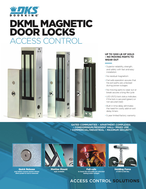
GATED COMMUNITIES • APARTMENT COMPLEXESMortise Mount style availableFail-safeto insure fire exit paths are unlockedduring power outagesHolding Forceof 300 to 600 lbs.DKML MAGNETICDOOR LOCKSACCESS CONTROLUP TO 1200 LB OF HOLD– NO MOVING PARTS TOWEAR OUT• S uperior reliability, strength,and safety with fast and easyinstallation• N o residual magnetism• F ail-safe operation assures thatfire exit paths are unlockedduring power outages• N o moving parts to wear out orbreak assures a long life cycle• L ED (R/G) lock status indicatesif the lock is secured (green) ornot secured (red)• B uilt in time delay eliminatesthe need for costly add-on exitdelay timers• 5 year limited factory warranty120 S. Glasgow Avenue,Inglewood, California 90301 U.S.A. Tel: 310-645-0023 FAX: 310-641-1586 © 2021 All Rights Reserved. Product specifications may change without notice. Rev. 4/21TECHNICAL FEATURESMECHANICALModelsLbs(force)DKML-S121200surface mount only, interior usesingle or dual doors, bracket sets available available with LED/Relay status, Delay timerDKML-S6600surface mount, interior usesingle or dual doors, bracket sets available available with LED/Relay status, Delay timer DKML-M6600mortoise mount, interior usesingle doors only, bracket sets available available with LED/Relay status, Delay timerADV ANCED FEATURESMagnetic locks have no moving parts to wear out or break which assures a locking device with an extremely long life cycleVandal resistant electromagnetic locks are vandal resistant making them ideal for practically any applicationDoor controls – a full range of exit buttons and door control devices provide easy exit capabilityMost locks are available with an LED status indicator giving a visual indication as to whether the lock is secured or notWhen wired with fire alarms, magnetic locksimmediately release the door that they are securing, assuring that fire exit paths are openMounting brackets available for the 1200 Lbs and 600 Lbs locks: armature housing and mountingbacket, L bracket, bracket set of L and Z brackets with hardware, angle bracket, and spacer barELECTRICALall models: 12 or 24 VDC field selectable dkml-S12, dkml-S6: 550 ma@12v, 275 ma@24v dkml-M6: 550 ma@12v, 275 ma@24vRelay contacts all locks: 24 VDC, 1 amp maximumMISCELLANEOUSdkml-S12-single: 10.5 lbs. (4.7kg) dual: 20 lbs. (9.07kg)dkml-S6-single: 4.5 lbs. (2.07kg) dual: 9 lbs. (4.08kg)dkml-M6: 4.5 lbs. (2.07kg)Important!1. I f power switch is not wired between DC source voltage and magnet, it will take a longer time to de-energize the magnet, simulating residualmagnetism. Refer to the installation wiring diagrams.2. Same room install - resistive.3. Installation location: Indoor dry.4. Relay output is designated as common.5. M agnetic locks should only be powered with DC voltage for proper operation. Use a UL Listed Regulated Power Limited source.DISTRIBUTED BY:MEMBER:DoorKing,®Inc.Access Control Solutions since 1948。
Philips 6100 系列推挡推杆智能门锁说明书
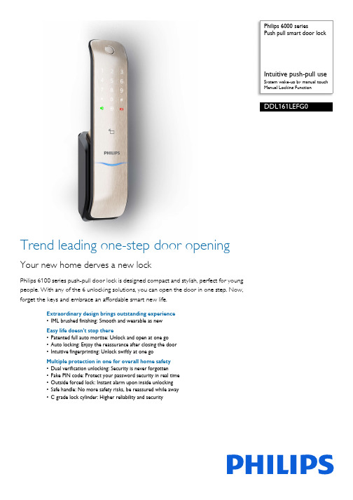
Philips 6000 seriesPush pull smart door lockIntuitive push-pull useSystem wake-up by manual touchManual Locking FunctionDDL161LEFG0Trend leading one-step door openingYour new home derves a new lockPhilips 6100 series push-pull door lock is designed compact and stylish, perfect for youngpeople. With any of the 6 unlocking solutions, you can open the door in one step. Now,forget the keys and embrace an affordable smart new life.Extraordinary design brings outstanding experience•IML brushed finishing: Smooth and wearable as newEasy life doesn't stop there•Patented full auto mortise: Unlock and open at one go•Auto locking: Enjoy the reassurance after closing the door•Intuitive fingerprinting: Unlock swiftly at one goMultiple protection in one for overall home safety•Dual verification unlocking: Security is never forgotten•Fake PIN code: Protect your password security in real time•Outside forced lock: Instant alarm upon inside unlocking•Safe handle: No more safety risks, be reassured while away•C grade lock cylinder: Higher reliability and securityHighlightsAuto locking functionPhilips 6100 series push-pull smart door lock employs full automatic mortise. Without the need for any extra action, the deadbolt will spontaneously pop out after you close the door. If the door is not locked properly, the mortise will give an alarm to remind you of the door lock status.Dual verification unlockingIn dual verification mode, you can use a combination of any two factors (fingerprint, password and card) as the unlocking solution to ensure doubled security for your home.Fake PIN codePhilips 6100 series push-pull smart door lock comes with the feature of Fake PIN Code technology which allows you to enter random number combinations to successfully getidentified as long as there is consecutive input of the real password. This feature caneffectively prevent peeping and safeguard your real password.IML brushed finishing The IML brushed surface has the hardness higher than 2H. Besides, it's waterproof, moisture proof and can keep fingerprint residue out.Intuitive fingerprintingThe fingerprint sensor is integrated in the push-pull handle so that when you hold the handle, your finger will naturally fall on the snesor. You can simply reach out andintuitively touch the sensor, then push to open after a successful fingerprint verification. The one-step unlocking feature will definately bring you a fast and convenient door opening experience.One-key outside forced lockBefore leaving home, you can touch theoutside forced lock key to enable the function.In this mode, opening the door from inside the room will trigger an alarm. This feature can effectively warn you of security risks and upgrade the level of home security.Patented full auto mortiseThe upgraded full automatic mortise makes it possible for instant unlocking right after a successful verification. Once you arerecognized, you can directly push or pull the handle to open the door, which greatlysimplifies the use of your door lock and brings you a fast and convenient in and out experience.Safe handle switchYou can enable the safe handle function before you leave home. After the door is locked, the indoor handle will be fixed to ensure that nobody could open the door by pushing the indoor handle. This feature can effectively prevents unlocking from indoor, thuseliminating security risks and improves anti-theft performance.Issue date 2023-11-28 Version: 1.2.1EAN: 69 71318 50060 2© 2023 Koninklijke Philips N.V.All Rights reserved.Specifications are subject to change without notice. Trademarks are the property of Koninklijke Philips N.V. or their respective owners.SpecificationsDesign & Appearance•Color: Champagne gold•Main Material: Zinc alloy•Surface Processing: Electroplating •Fingerprint Sensor: Semiconductor •Emergency Escape Design: Indoor fast opening mortise•Ergonomic Design: Push-pull handle design Access Solution•Fingerprint•Password/PIN Code•Card/Key Tag•Mechanical KeyLock Capacity•Fingerprint: Up to 100•Card/Key Tag: Up to 100•Master PIN Code: 1•User PIN Code: Up to 10•One-time PIN Code: 1Power Specification•Power Supply: 4 AA batteries•Battery Type: Alkaline Batteries•Time of Use: 8 months*•Maximum Batteries Capacity: 8 batteries •Emergency Power Supply: 5V power bank •Working Voltage: 4.5-6VEasy Operation•Indicator: Door locks status prompt, Low battery prompt, Mute status prompt, Outside forced lock prompt, System locking prompt•Voice Guide: Human voice guide Smart Lock Functions•Mortise: Full auto mortise, Super B-class lockcylinder•Locking Function: Electronic deadlock, Systemlocking•Safety Function: Dual verification, Fake PIN code,Outside forced lock function, Safe handle funtion•Alarm Function: Anti-dismantle alarm, Anti-pryingalarm, Outside forced lock alarmMode•Operationg Mode: Auto mode, Manual mode•System Setup Mode: Dual verification mode,Normal modeInstallation•Door Thickness: 38-60 mm, 60-90 mm, 90-120mm, Other range*•Door Opening Direction: Left inward opening, Leftoutward opening, Right inward opening, Rightoutward oepning•Door Type: Antitheft door, Copper door,Wooden doorAccessory Parts•Accessorial Battery: 4 AA alkaline batteries•Mechanical Key: 2 keys•Smart Key Tag: 2 cards•Installation Accessories•Mortise•Mounting Plate•Drilling Template•Certificate•Cleaning Pad•User Manual•Warranty Card•Quick Start Guide*May be less depending on the actual usage.*Please contact our service agents or authorized dealers for otherdoor range.。
智能门锁使用说明书_指纹锁
目录1 指纹锁介绍 (4)1.1 产品特征 (4)1.1.1 产品介绍 (5)1.1.2 产品功能介绍 (5)1.2 尺寸 (5)1.3 技术参数 (6)2 操作使用 (7)2.1 放置手指的方式 (7)2.2 操作说明 (8)2.3 警示 (8)2.4 安装/更换电池 (9)3 安装步骤图 (10)3.1 侧条和锁体尺寸图 (10)3.2 确认开门方向 (14)3.3 门板开孔图 (15)3.4 门扣盒开孔图 (15)3.5 安装步骤 (15)3.5.1 安装锁芯 (15)3.5.2 安装前后面板 (16)3.5.3 安装门框盒和扣板 (17)4 锁的维护及保养 (19)4.1 日常维护及保养 (19)4.2 使用须知 (19)5 售后服务 (20)5.1 售后服务相关说明 (21)5.2 装箱清单 (24)5.3 配件表……………………………………………………………24A/1(2016年5月)重要提示1指纹锁作为高科技产品,安装的好坏直接影响到门锁的正常操作及使用寿命,建议您聘请对锁具有相当经验的师傅进行安装,并根据产品附件中门板开孔图样板进行开孔,凿支承窝,锁扣板及锁扣盒孔;确认所开凿的孔准确无误,然后严格按照产品说明书中的步聚进行操作,如果安装后发现锁开关不灵活或不能开启,请及时和当地的经销商或本公司的售后服务部门联系,以便问题快速得以解决。
2如果您的房间正在装修中,我们建议您在产品安装及经检查没问题后将产品卸下,待装修完成后再把产品重新装上,这样做的目的是:1.避免装修过程中出现腐蚀性物质粘在锁体上,影响外观,如果门的油漆未干会影响传动不灵活;2.装修时会使用酒精、油漆等化学物质,这些化学物质在未干透时会向空气中散发腐蚀性气体或灰尘,加速产品表面处理生变,影响外观及降低产品使用寿命。
3在门锁安装前,请您先接通所有连接线并装好电池后,按门锁线路板上的初始化按钮,第一时间对门锁进行初始化,恢复到出厂状态。
门禁控制器使用说明书

CK100系列(CK100、CK1002、CK1003、CK1005、CK1006等)门禁控制器使用说明书一、产品简介CK100系列非接触式感应卡门禁控制器是现代先进的门禁系统,它选用最新中央处理器及大容量存储芯片,采用FLASH最新技术,所有资料不会因断电而丢失;具备感应卡开门、卡加密码开门、密码开门、遥控开门等多种开门方式。
门状态监视、输出报警、防拆等完善的保安措施让用户更加安全;开门按钮、遥控开门、关门提醒、门铃、可接常开或常闭锁等强大功能让用户更加方便。
CK100系列可以进入编程状态后增加或删除用户卡;为了方便操作,CK100系列设计了一种更加方便的方法,即使用授权卡或删除卡进行对用户卡的增加或删除。
二、技术参数1)工作电源:直流,电压12V,电流<0.1A2)最大负载:报警输出100mA,电锁输出5A3)外型尺寸:116mm×116mm×20mm4)重量:180g5)环境温度:-20℃- 60℃6)相对湿度:20% - 90%7)存储容量:有打卡记录机型:4000 张用户卡、4000组密码;无打卡记录机型:5500 张用户卡、5500组密码;无打卡记录、无密码、无代码机型:10000张用户卡(此机型无代码,不能按代码删除卡号)8)读卡距离:>10CM9)读卡类型:EM或EM兼容卡三、设置方法1)初始编程密码为“8888”。
2)进入编程状态:按 * 编程密码 # 进入编程状态,此时蓝灯闪烁加快。
可以输入以下介绍的“0”到“9”的命令进入不同的模式。
输入“0”到“9”的命令时蓝灯闪烁更加加快表示已经进入到设置。
3)功能设置(需在编程状态下)●按 * 编程密码 # 进入编程状态后按 0 新密码 # 重复新密码 # 注密码为1-8 位任意数字,蜂鸣器“嘀”的一声代表修改密码成功,连续“嘀嘀嘀”的三声代表失败,失败的原因一般是二个密码不一样。
●增加用户卡或开门密码(命令“1”)(1)增加用户卡:按 * 编程密码 # 进入编程状态后按 1 读卡输入该卡代码 #注:卡的代码为0001-9999 不可重复的四位数字,作为将来在该卡丢失时删除该卡的代码,可以不输入代码,但不输入代码时将来将不能单独删除该卡,如需连续增加卡则在输完四位数的代码后不必按#直接读第二张卡,不需要代码时可直接读第二张卡,第三张卡等。
