BKHTB-82I6中文资料
BYW82中文资料
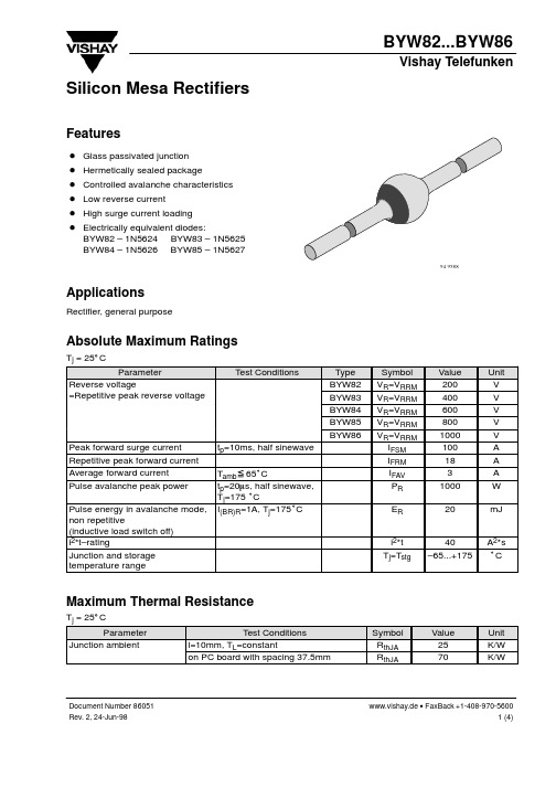
Figure 6. Typ. Diode Capacitance vs. Reverse Voltage
Z thp – Thermal Resistance for Pulse Cond. (K/W)
1000
100 tp/T=0.5 tp/T=0.2 10 tp/T=0.1 tp/T=0.05 tp/T=0.02 1 10–4 tp/T=0.01
tp=10ms, half sinewave Tamb 65°C tp=20ms, half sinewave, Tj=175 °C I(BR)R=1A, Tj=175°C
x
40 –65...+175
Maximum Thermal Resistance
Tj = 25_C Parameter Junction ambient Test Conditions l=10mm, TL=constant on PC board with spacing 37.5mm Symbol RthJA RthJA Value 25 70 Unit K/W K/W
Peak forward surge current Repetitive peak forward current Average forward current Pulse avalanche peak power Pulse energy in avalanche mode, non repetitive (inductive load switch off) i2*t–rating Junction and storage temperature range
www.vishay.de • FaxBack +1-408-970-5600 2 (4)
宏泰HTB说明书

宏泰H T B说明书集团档案编码:[YTTR-YTPT28-YTNTL98-UYTYNN08]HT-110B-6固定点防盗电话联网报警系统公司通过ISO90001国际质量管理体系认证公司产品通过公安部安全与警用电子产品质量检测中心质量认证使用说明书使用本报警器前请详细阅读此说明书一、概述:HT-110B-6固定点防盗电话联网报警系统,采用微电脑芯片技术,智能化程度高,可靠性能好。
系统由报警主机、无(有)线红外探测器、无线门磁、无线遥控等组成。
还可选配其它探测传感器。
系统利用邮电市话、移动电话和传呼网络传递报警信息,操作简便。
是智能家居安全防范精品。
二、报警工作原理:在监控区域安装好无(有)线红外探测器、无线门磁,将报警主机与电话外线联接,设定接警电话、手机或呼机号码,预先自录报警语音。
当报警器处于“布防”状态时,若盗贼闯入监控场所,报警器立即报警并自动拨打预先设定的电话、手机或传呼机,发出报警信息。
接警电话里先听到用户预录的报警语音,说明报警地点,随后转入报警现场监听,有利接警人及时掌握现场情况,作出反应。
“紧急报警”功能可应付抢劫等突发事件。
三、功能特点:1、八个无线防区,两个有线防区,电话号码键盘输入,可存贮1-7组26位电话、手机、传呼机号码。
2、自录报警语音,可重放录音效果,报警时向接警人播出报警语音。
之后主机自动转入现场监听。
有利接警人掌握现场情况,作出反应。
3、电话外线防剪报警:一旦电话外线被剪断或短路,本机每60秒响“嘀”一声提示音,表示线路故障(须通过电话线检测开关设置)。
4、无线探测器、遥控器、门磁与主机之间采用学习式自动对码,增配探测器、遥控器更加方便快捷。
5、布防1(外出布防),布防2(留守布防)两种布防方式,方便留守(主人在家或值班)人员的布/撤防选择。
6、通过遥控器控制主机“布防”、“撤防”、“紧急报警”。
7、具有优先报警功能:当电话占线时,优先拨打报警电话。
8、全新的人性化操作方法:所有功能设置为一键式快捷选择,无需记忆繁琐的操作说明,一看就会9、配备微功耗无线红外探测器、无线门磁,实现全方位监控报警。
BK2新产品培训

注:对于符合公差带E的产品制造厂应增加字母E加以指示
1
BK2M智能型
1、 主电路进线接线端子 2、 本体辅助接线端子 3、 电磁铁和脱扣器电源端子 Ⅱ 产 品 介 绍 4、 合闸、分闸指示窗口 5、 手柄断开位置锁 6、 手柄
2 3
4 5
7 8 9 10
17
6
7、 复位试验按钮
8、 智能脱扣器 9、 功能端子接线端 10、主体出线接线端子
Ⅰ
基 础 知 识
护开关电器》。
◎电气符号
2
功能特点
采用模块化单一结构型式,将断路器、接触器、 热继电器、隔离开关等多元器件集成。
◎具有远距离自动控制和就地直接人力控制功能
Ⅰ
基 础 知 识
◎具有面板指示及机电信号报警功能 ◎具有过压欠压保护功能 ◎具有断相缺相保护功能 ◎具有协调配合的时间-电流保护特性 (具有反时限、定时限和瞬时三段保护特性)
20
2
BK2附件
1、主体开关
1
3
2、隔离模块
Ⅱ 产 品 介 3、外置辅助模块 4、外挂信报模块 5、可逆模块
4
绍
(大图)
5
21
BK2隔离模块
◎实现主电路安全、可视的隔离断点,标配1组隔离 触头。
◎可与产品本体配套安装(进线侧),亦可独立安装。
Ⅱ 产 品 介 绍 ◎产品本体分断状态下,方可进行隔离模块的安全操 作,可实现与产品本体机械联锁,隔离模块连接和断 开位置均可加锁防护。 ◎订货单号:WKGL1。
不够用时,可增选此模块,固定于产品本体
Ⅱ 产 品 介 绍
左侧(上) ◎外置辅助模块提供两种形式: 两开一闭的辅助接点 一开两闭的辅助接点 ◎订货单号:WKFZ21或WKFZ12
得力 DL82、DZ82系列扫描仪用户手册 说明书

请将装置尽量靠近计算机,让接口数据线能够轻松地连接装置与计算 机。
请勿将装置或其电源适配器放置在下列环境中: 室外 靠近灰尘、水或热源 易受电击、震动、温度极高或极低、湿度高及阳光直射的位置
使用本装置时请保持手部干燥。避免造成电击伤害。 除非装置文件中另有明确说明,否则切勿自行拆卸或试图改装电源适配
保证
本书内容若有更动,本公司将不另行通知。 本公司对本文档内容不做任何保证,包括(并不限于)对某项特殊目的的适 用性的隐含保证。 对因此造成的错误,或因装修、效能或本产品使用上造成的不固定或严重 损害,本公司不负任何责任。
CCC_EMI 警告 警告: 在居住环境中,运行此设备可能会造成无线电干扰。 *本产品属于第一级 LED 产品。
5. 保养及维修扫描仪.................................................. 5-1
5.1 清理扫描仪玻璃镜片 ....................................... 5-1 5.2 清洁自动进纸装置 .......................................... 5-2 5.3 执行清洁模式 ............................................... 5-5 5.4 清洁超声波感应器 .......................................... 5-6 5.5 擦拭玻璃镜片 ............................................... 5-7 5.6 耗材更换 ..................................................... 5-8
BKM800E博康说明书_new_1(2011-08-23)
前言本公司长期以来是从事电力系统自动化系统及设备研究、开发、生产的高科技企业。
公司在电力系统自动化方面已研制成功了多种自动化系统及设备,现已推出《BKM800E微机保护测控装置》适用于6~35KV变电站及开闭所等使用环境。
BKM800E系列微机保护装置从变电站整体出发,综合考虑了保护、控制、信号、监测、通讯、防误、事件记录等多种功能,采用工业级进口贴装元件、在测量精度、稳定性、安全可靠性、电磁兼容性以及抗干扰等电气特性方面均有大幅度的改进,箱后接线方式,使装置具有安装、维修方便的特点,另外将谐波处理纳入整体成套范围,《BKM800E微机保护测控装置》包括线路保护测控装置(带进线备投)、配电变压器保护测控装置、电动机综合保护测控装置、电容器保护测控装置、母联分段保护测控装置、微机PT监测切换装置、微机所用变测控装置。
《BKM800E微机保护测控装置》配套的后台监控系统介绍及说明将另行编辑印刷。
目录第一部分 (1)液晶显示画面和操作 (1)1、液晶显示画面和操作 (2)1.1 状态指示: (2)1.2 按键 (2)1.3“主菜单”界面显示 (3)第二部分 (11)装置分类介绍 (11)■BKM800E-L线路保护测控装置 (12)1、主要功能 (12)2、保护功能 (12)3、定值参数一览表 (14)4、保护定值整定说明 (14)5、端子图 (16)6、接线图 (17)7、保护装置操作回路原理图 (18)■BKM800E-TC厂用变保护测控装置 (19)1、主要功能 (19)2、保护功能 (19)3、定值参数一览表 (20)4、端子图 (21)5、接线图 (22)6、保护装置操作回路原理图 (23)■BKM800E-MB电动机保护测控装置 (24)1、主要功能 (24)2、保护功能 (24)3、定值参数一览表 (25)4、端子图 (26)5、接线图 (27)6、保护装置操作回路原理图 (28)■BKM800E-C电容器保护测控装置 (28)1、主要功能 (29)2、保护功能 (29)3、定值参数一览表 (30)4、端子图 (30)5、接线图 (31)6、保护装置操作回路原理图 (32)■BKM800E-LBT线路保护测控装置(带进线备投) (33)1、主要功能 (34)2、保护功能 (34)3、定值参数一览表 (35)4、端子图 (36)5、接线图 (37)6、保护装置操作回路原理图 (39)■BKM800E-MJ 母线监测保护测控装置 (40)1、主要功能 (41)2、保护功能 (41)3、定值参数一览表 (41)4、端子图 (42)5、接线图 (42)6、保护装置操作回路原理图 (44)■注意事项: (44)1、现场安装及调试 (45)2、投运说明及注意事项 (46)3、运输、贮存注意事项 (47)4、常见问题 (47)附录一保护逻辑图 (48)附录二BKME800E型安装及开孔尺寸图 (51)第一部分液晶显示画面和操作1、液晶显示画面和操作装置上电后,将显示循环界面1,如下图所示。
BA5826FP资料
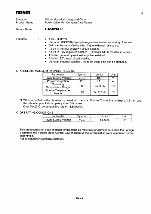
Please contact our sales offices for details ;
U.S.A / San Diego Atlanta Dallas Germany / Dusseldorf TEL : +1(858)625-3630 TEL : +1(770)754-5972 TEL : +1(972)312-8818 TEL : +49(2154)9210 FAX : +1(858)625-3670 FAX : +1(770)754-0691 FAX : +1(972)312-0330 FAX : +49(2154)921400 FAX : +44(1)908-282-528
Appendix1-Rev1.1
Contact us
Attached-1
Thank you for your accessing to ROHM product informations. More detail product informations and catalogs are available, please contact your nearest sales office.
The products listed in this document are designed to be used with ordinary electronic equipment or devices (such as audio visual equipment, office-automation equipment, communications devices, electrical appliances and electronic toys). Should you intend to use these products with equipment or devices which require an extremely high level of reliability and the malfunction of with would directly endanger human life (such as medical instruments, transportation equipment, aerospace machinery, nuclear-reactor controllers, fuel controllers and other safety devices), please be sure to consult with our sales representative in advance. About Export Control Order in Japan Products described herein are the objects of controlled goods in Annex 1 (Item 16) of Export Trade Control Order in Japan. In case of export from Japan, please confirm if it applies to "objective" criteria or an "informed" (by MITI clause) on the basis of "catch all controls for Non-Proliferation of Weapons of Mass Destruction.
BX06BK 智能PCM设备 用户手册V1.1(有标)
4.1 组网应用 .................................................................. 53 4.2 组网方式 .................................................................. 53
目录
安全使用须知 .................................................. 1 第一章 基础知识 ............................................... 1
1.1 通信网简介.................................................................. 1 1.1.1 通信网的分类 .......................................................... 1 1.1.2 通信网的基本要素 ...................................................... 1 1.1.3 通信网的发展方向 ...................................................... 1
2.2 系统工作原理................................................................ 8 2.3 硬件结构 ................................................................... 8 2.4 软件结构 ................................................................... 9 2.5 系统特点 ................................................................... 9 2.6 整机配置注意事项........................................................... 10
BK8602.8602K系列读卡器
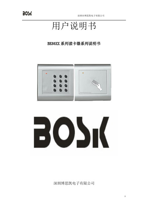
用户说明书BK86XX系列读卡器系列说明书深圳博思凯电子有限公司BK86XX系列读卡器系列说明书BK86XX系列的非接触式射频读卡器,采用先进的射频通讯电路及嵌入式微功耗微处理器设计,具有接收灵敏度高、工作电流小、抗干扰能力强、性能价格比高等特点。
其独特的外观设计、标准的86电气安装结构,使用安装更加灵活方便,被广泛适用于门禁、考勤、在线巡更等各种射频识别应用领域。
BK86XX读卡器为工作频率为125KHz的非接触式射频ID卡读卡器,它釆用先进的射频接收线路设计及嵌入式微控制器,结合高效译码算法,完成对EM兼容式ID卡的接收,具有接收灵敏度高﹑工作电流小、抗干扰能力强、性能价格比高等特点。
其新颖的外观设计、标准的86电气安装结构,使用安装更加灵活方便,被广泛适用于门禁、考勤、停车场等各种射频识别应用领域。
读卡器的使用与操作l.使用说明读卡器通电后, 黄灯常亮, 蜂鸣器鸣一声,当有效卡接近时, 黄灯转绿灯,到达设定时间后再变为黄灯;当无效卡接近时, 黄灯转红灯,然后再变为黄灯。
读卡后, 若ID卡仍在射频卡应区内读卡器将不重读该卡号。
同一ID卡,读卡后在极短时间内迅速离开射频卡应区又进入该区时,读卡器将不读该ID卡号。
不同ID卡分别进入射频卡应区范围,读卡器将连续读卡。
2.安装步骤:预先在墙面上安装标准的86电气底盒。
打开读卡器前面罩(两侧有两小孔,用螺丝刀分别撬开两侧即可 ),用螺丝将读卡器底座固定到电气底盒上。
然后按定义要求将读卡器数据线紧固到相应的接线端子上,并插装到读卡器面板上的插座上。
确认无误后将读卡器面板扣装到底座上即可。
注意事项!!:1.最大读卡距离是在无干扰环境中,读卡器按照正确方式安装,且卡片平行于读卡器表面测得,任何电磁干扰环境都将影响读卡距离。
2.严禁将读卡器安装于磁性金属物体表面,金属材料将严重影响RF信号。
3.严禁将读卡器安装于产生干扰电磁场设备附近,如:马达、AC/DC转换器、UPS、继电器、监视器等。
BK使用说明书详解
使用说明书JW-BK系列静态容量法比表面及孔径分析仪目录1.原理及方法1.1氮吸附比表面测定方法1.2静态容量法2.仪器结构与安装2.1机型及配置2.2 结构2.3硬件安装2.4软件安装3.测试界面功能详细说明3.1文件(F)3.2设置(C)3.3操作(D)3.4查看(V)3.5窗口(W)3.6帮助(H)3.7新建3.8打开3.9保存3.10设置界面的显示效果3.11设置系统固定参数3.12设置吸附、脱附参考压力3.13开始吸附3.14终止吸附3.15开始脱附3.16终止脱附3.17数据预览3.18打印3.19关于3.20阀门控制3.21予抽3.22充气3.23升降控制3.24当前气压3.25实验开始和终止时间3.26页面上实验过程的实时显示4.实验程序4.1装样和称样4.2样品管安装4.3予抽4.4预处理4.5样品条件与仪器参数设定4.6存储路径设定4.7实验项目及压力设定4.8液氮杯及密封4.9开始试验4.10实验过程实时显示4.11实验数据预览4.12实验结束4.13重量复核4.14数据保存4.15实验结果及测试报告4.16打印5. 真密度测试6.BK系列不同产品的若干差异6.1预处理位置及操作方法6.2传感器类型及显示方法6.3压力设置及平衡时间的控制方法6.4具有微孔分析功能的产品6.5双样品测试6.6多工作站7.影响测试结果的因素7.1样品本身因素7.2预处理的充分与否7.3样品称样量及精度7.4真空度7.5真空泄漏7.6温度7.7气压7.8液氮纯度7.9液氮杯的密封7.10温度延时7.11样品管的位置7.12测试条件的选择8.仪器维护及常见故排除8.1 真空系统维护8.2 充气速度调整8.3 防止样品抽飞8.4真空抽不上8.5真空阀门不密封8.6管路的污染8.7预处理系统结构与故障9.安全注意事项10.微孔测试10.1微孔测试程序10.2吸附泵的应用10.3微孔测试报告【附录1 】物理模型及分析方法使用说明书简单说明:本说明书是针对JW-BK系列比表面及孔径分析仪而编写的,该系列的仪器是采用低温氮吸附和静态容量法的原理设计的,这是国际上通用的方法,与美国康塔公司、麦克公司生产的比表面及孔隙度仪在原理和功能上都是相同的,但是在具体的结构与操作与软件细节上,各有特点,本使用说明书对本机尽量做详尽的说明,目的是帮助用户用好仪器,知其然并知其所以然,为提高中国仪器的技术水平和使用水平做出努力。
BKAE2A234MAB40101SA资料

ARINC 600 BKAD/E/F Low insertion force contacts.Both environmental and non- environmentalversions.Polarizing posts that are removable from themating face.Field replaceable inserts for size 22 andpower contacts.Up to 800 size 22 contacts in one connector.Crimp, coax, power, printed circuit and wirewrappable post style contacts.Uses standard DPX crimp, insertion/extractiontooling.Waveguide connections available.BKAD/EBKAD/E connectors represent a major milestones in presenting a new rack and panel connector for support of the air transportation market.Several important design concerns have been ad-dressed and solved in this new series. High mating forces of pluggable modules in a rack have been reduced by approximately two-thirds.The low insertion force contacts are also inter-changeable with the contacts used in the DPX series and permit retrofit of existing equipment.BKAFThis new connector is totally intermateable and intermountable with ARINC 600 connectors now in the field.The BKAF permits the user to easily replace a contact in case of problems, rather than disas-semble the entire connector--it is available with size 22 contacts in wrap post or solder-tail ver-sions. The system maintains the advantages of low insertion force technology incorporated in all ARINC 600 connectors.Rear Release/Rear Removable Size 12, 16, 20, 22 Crimp Contacts Front Release/Front RemovableSize 22 Solder Tail and Wrap Post ContactsPos-Aline Connector Construction FeatureMaterial Specifications In the ARINC 600 connector series, Size 22 con-tacts are the only size that utilize this designfeature. The hooded socket extends from its in-sulator while the pin contacts are shrouded by itsfront insulator.All other contacts used in this series employ stan-dard contact design.The result is that the complement of contacts forthe plug connectors will consist of pin contacts forsize 22 and socket contacts for all others. Thereceptacle contacts will be just the reverse, socketcontact for size 22 and pin contacts for thebalance.Shell & WaveguideBKAD BKAE BKAF SpecificationsInsulatorContactsGrommets/Seals O-Ring FinishMaterialMaterialMaterialFinishTerminationMaterialMaterial1200AlodineThermosetAluminum alloyCopper alloyGold over NickelCrimpN/AN/A1200AlodineThermosetAluminum alloyCopper alloyGold over NickelCrimpSilicone-based ElastomerSilicone-based Elastomer1200AlodineThermosetAluminum alloyCopper alloyGold over NickelP.C./Wrap PostN/AN/AMIL-C-5541N/AQQ A-591/A380QQ-C-533MIL-G-45204N/AN/AN/A* = For Polarizing Position greater then 99, add third digit. ARINC 600 BKAD/E/FCONNECTOR SERIES CLASS SHELL SIZECONNECTOR LAYOUT DESCRIPTION SIZE 1 COAX INSERT MODIFIER BOEING COAX MODIFIER SHELL STYLECONNECTOR MOUNTING MODIFIER POLARIZING POSITIONMODIFIER (Contact, Finish, Material)How to OrderBKA D 2 A234 M * 3 00 01 * F0CONNECTOR SERIESBOEING COAX MODIFIERSHELL STYLECONNECTOR MOUNTING MODIFIERCLASSNon-environmental (rear release, crimp contacts)Environmental (rear release, crimp con-tacts)Non-environmental (front release, solder and wrap post #22 contact, rear release all others)Same as E, except uses BKAD shells, and Less 0 rings on plug side.Environmental (0-ring is used to seal between connector shell and insulators)with rear release, crimp contacts.Non-environmental connector using fil-tered contacts (reference Cannon Phoe-nix)Max. contact capacity - 125Max. contact capacity - 400Max. contact capacity - 800Connector contains modified 71W1 or 2W2 insert (four MTG screw hole loca-tions and coaxial contact used in this insert are interchangeable between dif-ferent manufacturersPlug (rack side)Receptacle (box side)Standard design, .148 dia. holesWith #6-32 ESNA (#12 NCFMA2-62) clinch nuts (see chart)Size 1 receptacle only - less 3 printed circuit board mounting lugsWith #4-40 ESNA (#22 NCFMA2-40) clinch nuts (see chart)Size 2 and 3 plug and receptacle only - with #4-40 ESNA (#22 NCFMA2-40) clinch nuts (all mounting holes)Size 2 and 3 plug and receptacle only - with #6-32 ESNA (#12 NCFMA2-62) clinch nuts (all mounting holes)Same as - 00 mounting modification except with nickel finished shells .0008 - .0012 thick with EMI grounding spring for plug shells and supplied with non-environmental inserts.Same as - 00 mounting modification except with nickel finished shells .0008 - .0012 thick with EMI grounding spring for plug shells and supplied with environmental inserts not potted into shell.With floating eyelets (.048 min. radial float)4 corner holes per connector.Consult factory if other modifications are requiredSHELL SIZECONNECTOR LAYOUT DESCRIPTIONSIZE 1 COAX INSERT MODIFIERNOTE: A dash must be inserted whenever code does not apply.D BKA (Per ARINC 600)E FC ST 3 -4 -00 -01 -02 -03 -08 -09 -16 -17 -23 -M123(See page 4)----------Boeing Coax Code Connector Size1234484610Number of Clinch Nuts Plug ReceptacleITTC Code Plug Connector Receptacle Connector ITTC Coax Contacts SuppliedAA AB AC AD AE AFBlank B C D E FNo Coax Supplied 349-0013-000 349-0015-000 349-0013-000 349-0017-000 349-0015-000 349-0018-000 349-0015-000 349-0017-000No Coax Supplied 349-0014-000 349-0016-000 349-0014-000 349-0002-000 349-0016-000 349-0004-000 349-0016-000 349-0002-000AR INC 600 B K AD/E/FHow to Order (Continued)CONNECTOR LAYOUT DESCRIPTION NOTE. ANY OTHER COMBINATION OF INSERTS WITHIN A SPECIFIC SHELL IS AVAILABLE UPON REQUESTPOLARIZING POSITIONMODIFIER (Contact, Finish, Material)01 thru 99 (per ARINC 600)Blank-Polarizing posts or keys not installed but supplied with connectorBlank -SC -WC -WD -SD -WA -WB -Rear release, crimp, signal and powercontacts supplied with connector (when applicable)Contacts not supplied with connector (FO not stamped on connector)Less contacts and waveguide (FOO notstamped on connector)Front release .025(0.63) D. x .150(3.81) solder post and crimp, rear re-lease power contacts (when applica-ble) supplied with connectorFront release .025(0.63) D. x .250(6.35) solder post and crimp, rear re-lease power contacts (when applica-ble) supplied with connectorFront release .025(0.63) D. x .375(9.53) solder post and crimp, rear re-lease power contacts (when applica-ble) supplied with connectorFront release .025(0.63) D. x .500(12.7) solder post and crimp, rear re-lease power contacts (when applica-ble) supplied with connectorFront release .025(0.63) Sq. x .250(6.35) (1 wrap) wrap post and crimp,rear release power contacts (when ap-plicable) supplied with connector Front release .025(0.63 Sq. x .375(9.53) (2 wraps) wrap post and crimp,rear relase power contacts (when ap-plicable) supplied with connectorFront release .025(0.63) Sq. x 500(12.7) (3 wraps) wrap post and crimp,rear release power contacts (when ap-plicable) supplied with connector Front release .025 (0.64) Sq. x 641(16.28) (3 wraps) wrap post and crimp, rear release power contacts (when applicable) supplied with con-nectorNOTE: COAXIAL CONTACTS TO BE ORDERED SEPARATELYFO -FOO -SA -SB -Layout included in the following ARINC configurations 702, 710, 711, 712, 714, 715, 716, yout included in the following ARINC configurations 707, 718 & 730.Layout included in the following ARINC configurations 701, 702, 703, 704, 705, 706, 724, yout included in the following ARINC configurations 701, 717, 726, 729.Note: All layouts with "OPEN' insert cavity are not supplied with an insulator. If a Blank insert is required please consult factory.Shell Dimensions - Size 1PlugRetainer Plate *This dimension indicates distance from centerline of retaining screw to the centerline of first contact cavity.For further information, refer to ARINC 600 specification or consult factory.Size 1 Receptacle Panel CutoutRetainer Plate Size 1 Plug Panel CutoutReceptacleFor further information, refer to ARINC 600 specification or consult factory.* This dimension indicates distance from centerline of retaining screw to the centerline of first contact cavity.BKAE SERIES 1.550 (39.37) MAXCBABKAE SERIES 1.670 (42.42)Shell Dimensions - Size 2 Plug11550 (39.37) MAXBKAE SERIES130 (3.30.120 (3.05)1.317 (33.45).355 (9.02)1.5301.670 (42.42)Retainer Plate*This dimension indicates distance from centerline of retaining screw to the centerline of first contact cavity.For further information, refer to ARINC 600 specification or consult factory.Size 2 Receptacle Panel Cutout Retainer Plate Size 2 Plug Panel Cutout ReceptacleFor further information, refer to ARINC 600 specification or consult factory.* This dimension indicates distance from centerline of retaining screw to the centerline of first contact cavity.Shell Dimensions - Size 3BKAE SERIES 1.550 (39.37) MAX1.670 (42.42 )MAXRetainer Plate ReceptaclePlugSize 3 Plug Panel Cutout* This dimension indicates distance form centerline of retaining screw to the centerline of first contact cavity.For furter information, refer to ARINC 600 specification or consult factory.Retainer Plate Size 3 Plug Panel Cutout* This dimension indicates distance form centerline of retaining screw to the centerline of first contact cavity.For furter information, refer to ARINC 600 specification or consult factory.Contact Arrangements - Shell Size 1Contact Arrangements - Shell Sizes 2 and 3BKAD/BKAE (Plug Rear face shown)BKAD/BKAE (Plug Rear face shown)REAR SURFACE WHITE ON BLUE TO INDICATE REAR RELEASE REAR REMOVAL CONTACTS ENGAGING END SURFACE WHITE ON RED TO INDICATE FRONT RELEASE FRONT REMOVAL CONTACTS**Pending ARINC release.NOTE: In layouts using #22 contacts mixed with any other contact size (20HD, 16, 12), the size #22 contact type (pin or socket) determines the insulator as a pin insert or a socket insert.(For Contact Cavity Location and Contact Cavity Identification refer to ARINC 600 or consult factory)REAR SURFACE WHITE ON BLUE TO INDICATE REAR RELEASE, REAR REMOVAL CONTACTS FOR INSERTS CONTAINING STANDARD SIGNAL & POWER CONTACTS(For Contact Cavity Location and Contact Cavity Identification refer to ARINC 600 or consult factory)30T228 #222 #8 TWINAX/COAX (#8 Grounded toShell)6060 #226**6 #86T6**6 #8(Metallic Insert)13W24 #20, 4 #12, 3 #162 #5 COAX24T4**20 #20, 4 #8100100 #228580 #22, 4 #20, 1 #1659**50 #22, 5 #16, 4 #1234**24 #20, 10 #1844 #125W21 #122 #162 #5 COAX4040 #226060 #225W21 #122 #162 #5 COAXBKAF - Available Receptacle Shell Only (Front Release)Shell Cavity A or BShell Cavity C or FShell CavityCShell CavityCShell CavityA or BContact Arrangements - Shell Sizes 2 and 3BKAD/BKAE (Plug Rear face shown)Shell Cavity A,B,D,E2W22 #1 COAX4W44 Modified #1 COAX (Metallic Insert)10T10**10 #8 TRIAX/COAX (#8 Grounded to Shell)(Metallic Insert)24**24 #1271W170 #221 #1 COAX 71W1B 70 #221 #1 COAX60**60 #2049T2**47 #202 #8110**100 #225 #12 & 5 #20** Pending ARINC release.(For Contact Cavity Location and Contact Cavity Identification refer to ARINC 600 or consult factory)REAR SURFACE WHITE ON BLUE TO INDICATE REAR RELEASE. REAR REMOVAL CONTACTS FOR INSERTS CONTAINING STANDARD SIGNAL & POWER CONTACTS150150 #22120T2 **118 #222 #8 TWINAX/COAX (#8 Grounded to Shell)121**110 #225 #166 #20Contact Arrangements - Shell Sizes 2 and 3BKAF - Available Receptacle Shell ONLY (Front Release)SHELL CAVITY A, B, D, E,BKAF - Available Receptacle Shell ONLY (Front Release)SHELL CAVITY C, F** Pending ARINC release.NOTE #22 CONTACTS ARE SOCKETS, 20HD,16, 12 ARE PIN CONTACTS.(For Contacts Cavity Location and Contact Cavity Identification refer to ARINC 600 or Consult Factory)ENGAGING END SURFACE WHITE ON RED TO INDICATE FRONT RELEASE FRONT REMOVAL CONTACTS FOR INSERTS CONTAINING STANDARD SIGNAL & POWER CONTACTSENGAGING END SURFACE WHITE ON RED TO INDICATE FRONT RELEASE, FRONT REMOVAL CONTACTS FOR INSERTS CONTAINING STANDARD SIGNAL & POWER CONTACTS71W170 #22150150 #226T6**6 #813W24 #203 #164 #122 #5 COAX100100 #2271W1B 70 #2210T10**10 #8121F**110 #22 6 #205 #16Waveguide ConnectionsPolarization (Engaging End)WAVEGUIDE DETAIL SHOWN FULLY ENGAGEDFULLYCENTERPOSTRIGHTPOSTLEFTPOSTCENTERPOSTRIGHTPOSTLEFTPOST INSULATOR ANDWAVEGUIDE RETAININGPLATEPlugBKA*1PLUG RECEPTACLE PLUG RECEPTACLEBKA*2BKA*3ReceptaclePolarizing PositionsPOSTDark area represents postPositionPositionLeft PostCenter PostRight PostLeft PostCenter PostRight PostPositionLeft PostCenter PostRight PostPositionLeft PostCenter PostRight PostPositionLeft PostCenter PostRight PostPositionLeft PostCenter PostRight PostPlug ShellReceptacle ShellKEYKit P/N 320-1067-000Kit P/N 320-1067-0030102030405060708091011121314151617181920212223242526272829303132333435363738394041424344454647484950515253545556575859606162636465666768697071727374750102030405060708091011121314151617181920212223242526272829303132333435363738394041424344454647484950515253545556575859606162636465666768697071727374751234561234561234561234561234561234561234561234561234561234561234561234561231111111111111111111111111111111111112222222222222222222222222222222222223331111116666665 55555444444333333222222111111666666555555444444333333222222111456123456123456123456123456123456123 456123456123456123456123456123456123456444444555555666666111111222222333333444444555555666666111111222222333333444444444444444444444444444444444444444333333333333333333333333333333333333222432165432165432165432165432165432165432165432165432165432165432165432165432444555555666666111111222222333333444444555555666666111111222222333333444444222222222222222222222222222222222111111111111111111111111111111111111666666165432165432165432165432165432165432165432165432165432165432165432165432165333333333333333333333333333333333444444444444444444444444444444444444555555111666666555555444444333333222222111111666666555555444444333333222222111111123456123456123456123456123456123456123456123456123456123456123456555555555555555555555555555555666666666666666666666666666666666666666666555555444444333333222222111111666666555555444444333333222222555555666666111111222222333333444444555555666666111111222222333333666666666666666666666666666666555555555555555555555555555555555555432165432165432165432165432165432165432165432165432165432165432165151152153154155156157158159160161162163164165166167168169170171172173174175176177178179180181182183184185186187188189190191192193194195196197198199200201202203204205206207208209210211212213214215216151152153154155156157158159160161162163164165166167168169170171172173174175176177178179180181182183184185186187188189190191192193194195196197198199200201202203204205206207208209210211212213214215216767778798081828384858687888990919293949596979899100101102103104105106107108109110111112113114115116117118119120121122123124125126127128129130131132133134135136137138139140141142143144145146147148149150767778798081828384858687888990919293949596979899100101102103104105106107108109110111112113114115116117118119120121122123124125126127128129130131132133134135136137138139140141142143144145146147148149150Contact and Termination Tooling DataBKA* (LIF) Crimp ContactsBKAF-ARINC 600 Size 22 Wrap Post Socket Contacts With .025(6.35) Square Wire-Wrappable Tails-Receptacle Only.BKA* Thermocouple ContactsBKAF Printed Circuit Solder Post Socket Contacts Size 22 with .025(6.35) Dia. Printed Circuit Tails-Receptacle Only.The new low insertion force, front-insertable, front-removable #22 socket contacts with .025(6.35) dia., PC tails are now availble for use in the BKAF non-environmental receptacle version only.These contacts can be sold separately or they can be supplied with a connector (see How to Order). Use part numbers shown in the table on the right when ordering separately.BKAD/F Solder Post, Power Pin Contacts (Captive)-Receptacle Only.Contacts are captivated between two unbonded insulator halves.BKAF Solder Post Pin Contact Front ReleaseFront Release Pin Contacts Size 20 and 16The new low insertion force, front-insertable, front-removable #22 socketcontacts with .025(6.35) square wire wrappable tails are now available for use in the BKAF non-enviornmental receptacle version only.These contacts can be sold separately or they can be supplied with a connector (see How to Order). Use part numbers shown in the table on the right when ordering separately.*Applies to BKAF 13W2 and 5W2 inserts only*Consult facotry for other available lengthsSize 5 Coax Contact (Rear insertable/removable)Size 12 Shielded Contact (Rear insertable/removable)Size 1 Modified Coaxial Contacts (4W4 Layout Only)Crimp Center Contact-Conforming to ARINC 600Part Number Style Solder Type Replacement Termination KitsCrimpType CoaxCoaxReplacement Termination KitsCable AccommodationPart Number Style Solder Type CrimpType Cable AccommodationRG316 DS RG142Various349-1051-002349-1044-000349-1042-000Straight Straight SMA Adapter320-1066-008320-1066-007N/A N/A RG214AA-5886RG393ECS 311201AA-5887AA-5888RG142Various349-1043-001349-1048-000349-1051-000349-1046-000349-1049-000349-1050-000349-1047-000349-1047-001Straight Straight Straight Straight Straight Straight Straight TNC Adapter320-1066-000320-1066-002320-1066-003320-1066-001320-1066-004320-1066-005320-1066-006320-1066-016320-1066-018320-1066-019320-1066-017320-1066-013320-1066-014320-1066-015----Plug ConnectorCustomer Use Drawings:All Coax contacts (except 349-1047-001) customer use drawing #349-0000-305Crimp termination kits: Customer use drawing #320-0000-305Solder termination kits: Customer use drawing #320-0000-304Receptacle ConnectorCustomer Use Drawings:Coax contacts 349-1051-002 and 349-1044-000 are located on cusomter use drawing #349-0000-304Coax contacts 349-1042-000 is located on cusomter use drawing #320-1042-000Sizes 1 Coax Contacts (71W1 layout only)Sizes 1 Coax Contacts (To be used with connectors containing 71W1A, 71W1B and 2W2 insert modifier-"M")Same standard coax contacts as used in ITT Cannon's DPX (ARINC 404) connector series.Designed to be interchangeable with contacts made by other manufacturers.Receptacle ConnectorPlug ConnectorSize 8 Coaxial ContactsSize 8 Twinax ContactsSize 8 Ground ContactsPlug ConnectorReceptacle ConnectorPlug ConnectorReceptacle ConnectorReceptacle ConnectorPlug ConnectorContact Type Socket Part Number *Engagement**TerminationShort Long Crimp RR-RR X -----349-1087-000-----349-1087-001349-1084-000349-1084-001349-1084-002349-1084-003349-1086-000349-1086-001349-1006-000349-1081-000----X X349-1007-000349-1080-000349-1080-001349-1080-002349-1080-003349-1082-000349-1082-001349-1088-000031-3300-000--X8, 10 AWG030-3306-000030-3306-001030-3676-000---X X8, 10 AWG 8, 10 AWG 8, 10 AWGX X -X-X -X -X ----X X X-X X X-X X XXXXXX X XX X XX X XX XX Crimp FR-RRSolder .250 (6.35)FR-FR .375 (9.52)RF Cable NumberContact Type Socket Part Number *Engagement**TerminationShort Long Crimp RR-RRCrimp FR-RRFR-FR .250 (6.35)Solder .375 (9.52)RF Cable NumberContact Type Socket Part Number *Engagement**TerminationShort Long Crimp RR-RR Crimp FR-RRSolder .250 (6.35)FR-FR .375 (9.52)RF Cable Number Contact Type Socket Part Number *Engagement**TerminationShortLong Crimp RR-RR Crimp FR-RRSolder .250 (6.35)FR-FR .375 (9.52)RF Cable Number Contact Type Socket Part Number * The electrical engagement of "Long" contacts is .150 (3.81) greater than the electrical engagement of "Short" contact.**RR-RR indicates rear release, rear removal. FR-RR indicates front release, rear removal. FR-FR indicates front release, front removal.*Engagement**TerminationShortLong Crimp RR-RRCrimp FR-RRSolder .250 (6.35)FR-FR .375 (9.52)Wire Size Contact Type Socket Part Number *Engagement**TerminationShortLong Crimp RR-RRCrimp FR-RRSolder .250 (6.35)FR-FR .375 (9.52)Wire Size Adams-Russell Co. Inc.FC11Z Adams-Russell Co. Inc.FC14ZAdams-Russell Co. Inc.FC11Z Adams-Russell Co. Inc.FC14ZM17/176-00002Tensolite Co.24463/9 B017X-2 (LD)Tensolite Co.24463/9 B017X-2 (LD)Tensolite Co.24463/9 B017X-2 (LD)Tensolite Co.24463/9 B017X-2 (LD)M17/176-00002Sealing Plugs-BKAE Environmental Connnectors OnlyFiller Plugs-BKAD Non-Environmental Connectors OnlyCavity ReducerDust CapsPart Number Contact Size Color A B C Part Number #5 Coax to #12 ContactCavity reducers are available when additional circuits are required for siz 12 power contacts. These reducers, having the internal configuration of size 12 power contact, are inserted into the size 5 coaxial insulator cavity to create size 12 power contact cavity.225-0094-000225-1013-000225-0070-000225-0071-000225-0072-000225-0090-000225-0095-000225-0096-000225-0097-000225-0098-000225-0099-000025-1121-001025-1122-001025-1123-001025-1124-001PinP/N 021-8756-000SocketP/N 021-8757-000Note: Supplied as standard for BKA product line only.BKAD 1-A & B-Plug BKAD 1-C-Plug BKAD 2&3-A & B-Plug BKAD 2&3-C-Plug025-1155-001025-1156-001025-1157-001025-1158-001BKAD 1-A&B-Receptacle BKAD 1-C-Receptacle BKAD 2&3-A & B-Receptacle BKAD 2&3-C-Receptacle22201612#5 Coax (Pin)22201612#5 and #9 Coax#5 and #9 Coax(Socket)Black Red Blue Yellow White Black Red Blue Yellow White.063 (1.6).085 (2.2).115 (2.9).171 (4.3).365 (9.3).040 (1.0).065 (1.6).075 (1.9).121 (3.1).287 (7.3).469 (11.9).469 (11.9).469 (11.9).564 (14.3).835 (21.2)White.069 (1.7).083 (2.1).131 (3.3).187 (4.7).275 (7.0).275 (7.0).051 (1.3).069 (1.7).108 (2.7).156 (4.0).251 (6.4).251 (6.4).420 (10.7).350 (8.9).320 (8.1).320 (8.1).450 (11.4)1.061 (26.9)Part Number Part Number Description Description Contact Size Color A B C P/N 225-0090-000Material: Teflon(All others thermoplastic)P/N 225-0099-000Material: Teflon(All others thermoplastic)BKAF P/N 225-1058-000(Size 22 - Black)(See Customer Use Drawing for details)Conductive dust caps protect against static electricity.AAAABBBBCCCCReplaceable InsertsPart NumberSocket AssemblyPin AssemblyClassBKAD BKAE BKAE BKAD BKAE BKAD BKAE BKAF BKAE BKAD BKAE BKAF BKAD BKAE BKAD BKAE BKAF BKAD BKAE BKAD BKAE BKAE BKAE BKAE BKAD BKAE BKAF BKAD BKAE BKAF BKAD BKAE BKAF BKAD BKAE BKAF BKAD BKAE BKAF BKAD BKAE BKAF BKAE BKAD BKAE BKAF BKAD BKAE BKAD BKAE BKAF 144-2944-000144-2944-000143-1156-001177-1000-002177-1000-002143-1912-000143-1912-001143-1141-000143-1154-001228-1026-002228-1026-001N/A228-1027-002228-1027-001143-1908-000143-1908-001143-1142-000143-1173-000143-1173-001143-1159-001143-1097-005143-1171-001143-1167-001143-3714-003143-1910-000143-1910-001N/A143-1958-000143-1958-002N/A143-2085-001143-2085-000N/A143-1113-000143-114-000N/A143-3877-000143-3879-000N/A143-2015-000143-2015-001N/A143-1182-000N/A143-1165-001N/A143-1150-002143-1150-001143-1906-000143-1906-001N/A144-2945-000144-2945-000143-1157-001177-1001-004177-1001-004143-1913-000143-1913-001N/A143-1155-001228-1012-003228-1012-001228-1015-001N/A228-1014-002143-1909-000143-1909-001N/A143-1174-000143-1174-001N/A143-1098-005143-1172-001143-1170-001143-3715-003143-1911-000143-1911-001143-2065-000143-1960-000143-1960-002143-2090-000143-2086-001143-2086-000143-2066-000143-1111-000143-1112-000143-1118-000143-3878-000143-3880-000143-1178-000143-2016-000143-2016-001143-2067-000143-1183-000143-1166-002143-1166-001143-1177-000143-1158-002143-1158-001143-1907-000143-1907-001143-2068-000Layout2W2**A4W4**5W266T610T1013W230T2344059*60-#20**60-#22**71W171W1A*71W1B85100110120T2121150Consult factory for Insert Part Numbers not listed.*Modified 71W1 insert to be used with connectors containing 71W1 insert modifier "M"**"Pin Inserts' accept receptacle coax contacts. "Socket Inserts" accept plug coax contacts.AR INC 600 R ack and Panel Connectors B K AD/E/FCross Reference-Part Number/Customer-Use DrawingCOMPONENT PART NUMBER CUSTOMER USE DRAWING NUMBERCOMPONENT PART NUMBER CUSTOMER USE DRAWING NUMBERCOMPONENT PART NUMBERCUSTOMER USE DRAWING NUMBER030-1975-009030-1975-010030-2259-000030-2273-000030-2280-000030-2286-000030-2356-000030-2357-000030-2358-000031-1113-009031-1113-010031-1287-000031-1302-000031-1303-000031-1308-000031-1351-000031-1351-001031-1351-002031-1351-003031-1352-000031-1252-000031-1252-002031-1352-003143-1908-000143-1908-001143-1909-000143-1909-001143-1910-000143-1910-001143-1911-000143-1911-001143-1912-000143-1912-001143-1913-000143-1913-001143-1958-000143-1958-002143-1960-000143-1960-002143-2015-000143-2015-001143-2016-000143-2016-001143-2065-000143-2066-000143-2067-000143-2068-000143-2085-000143-2085-001143-2086-000143-2086-001249-1521-002249-1522-009249-1522-010249-1554-002249-1604-003249-1604-004249-2201-000249-2202-000249-5027-013249-5027-015249-5027-016320-0051-000320-1066-000320-1066-001320-1066-002320-1066-003320-1066-004320-1066-005320-1066-006249-1521-002249-1522-010249-1522-010249-1554-002249-1604-003249-1604-004249-1521-002249-1522-010249-5027-013249-5027-007249-5027-0161250Y320-000-305025-1121-001025-1122-001025-1123-001025-1124-001025-1155-001025-1156-001025-1157-001025-1158-001025-0000-054(Conductive Only)025-0000-055(Conductive Only)225-0000-014225-0094-000225-0095-000225-0096-000225-0097-000225-0098-000225-0099-000225-1058-000225-0072-000225-0090-000225-1013-000225-1014-000225-1015-000225-0000-006225-0090-000225-0000-008143-0000-081143-0000-077143-0000-080143-0000-079143-0000-0781247Y 143-0000-079249-1521-000249-1522-000249-1522-002249-1554-000249-1604-000249-1604-001249-5027-008249-5027-017249-5027-000249-5027-007349-0000-306249-1521-000249-1522-000249-1522-002249-1554-000249-1604-000249-1604-001249-1604-002249-1882-000249-1882-002249-1885-002249-5027-008249-5027-017249-5123-000249-5123-001349-1053-000349-1053-001349-1053-002349-1053-003349-1053-0043491053-005349-1053-006349-1053-007349-1053-008349-1053-009030-1975-009030-1975-010030-2259-000030-2273-000030-2280-000030-2286-000030-2356-000030-2357-000030-2358-000031-1113-009031-1113-010031-1287-000031-1302-000031-1303-000031-1308-000031-0000-343031-0000-344021-0144-000021-0144-001021-0144-002021-0144-003021-0144-004021-0144-006021-0144-008021-0144-011021-0144-000021-0144-001021-0144-002021-0144-003021-0144-004021-0144-006021-0144-008021-0144-011349-0013-000349-0014-000349-0015-000349-0016-000349-1003-000349-1009-000349-0000-000349-0000-001349-0000-002349-0000-001349-000-301249-1767-000249-1767-001249-1768-000249-2203-000249-1767-000249-1767-001249-1768-000249-2203-000143-1906-000143-1906-001143-1907-001143-1907-001143-0000-079ContactsReplacement Coax Termination KitDust CapsFiller PlugsSealing PlugsReplacement Coax Body AssemblySize #1 Coax ContactsSize #5 Coax ContactsSize #12 Shielded ContactReplaceable InsertsFor part numbers not listed, consult ITT Cannon for applicalbe customer-use drawing.。
BK系列称重传感器产品简介
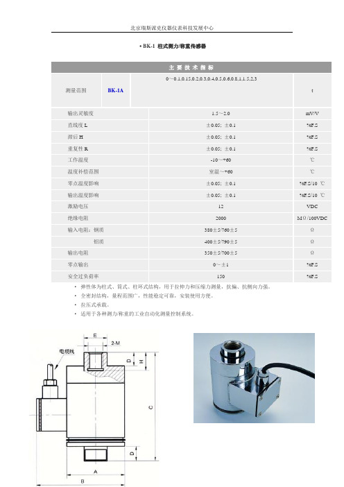
·弹性体为柱式、筒式、柱环式结构,用于拉伸力和压缩力测量,抗偏、抗侧向力强。
·全密封结构,量程范围广,性能稳定可靠,安装使用方便。
·拉压式承载。
·适用于各种测力/称重的工业自动化测量控制系统。
测量范围
BK-1A
0~0.1,0.15,0.2,0.3,0.4,0.5,0.6,0.8,1,1.5,2,3
绝缘电阻
2000
MΩ/100VDC
输入电阻:钢质
380±5/760±5
Ω
铝质
400±5/790±5
Ω
输出电阻
350±5/700±5
Ω
零点输出
0~±1
%F.S
安全过负荷率
150
%F.S
量程(t)
A
B
C
D
E
2-M
H
0.1,0.15,0.2,0.3,
0.4,0.5,0.6,0.8,1
ø63
95
120
16
ø25
t
输出灵敏度
1.5~2.0
mV/V
直线度L
±0.05;±0.1
%F.S
滞后H
±0.05;±0.1
%F.S
重复性R
±0.05;±0.1
%F.S
工作温度
-10~+60
℃
温度补偿范围
室温~+60
℃
零点温度影响
±0.05;±0.1
%F.S/10℃Βιβλιοθήκη 输出温度影响±0.05;±0.1
%F.S/10℃
激励电压
12
VDC
M16X1.5-6H
20
1.5,2,3
手持式食品安全快速检测仪
轻触参考资 料信息内容 可显示PDF 格式内详细 信息
BK-iMTⅡ软件功能介绍
长按检测任务 ,可接收本条 任务,接收后 的任务不会再 显示在任务接 收列表中
Instrument
BK-iMTⅡ软件功能介绍
任务查询
需要对已经接收的 任务的执行状态进 行查询或结果的导 出需要进行如下操 作: 在首页中选择“任 务管理”,点击“ 任务查询”
2、仪器关闭
使用完毕后,确认检测仪器内没有检测卡等物品之后,长按电源键关闭手持 式检测设备或者在“设置”选项中点击“关机”选项,即可进行关机操作。
(1)长按电源键 3-5秒关闭仪器
BK-iMTⅡ硬件操作介绍
(2)在“设置”选 项中点击“关机” 选项,即可关闭仪 器
BK-iMTⅡ食品安全检测管理系统简介
Instrument
BK-iMTⅡ快速检测项目示例
(4)样品检测
点击所接受的任 务进行任务检测
BK-iMTⅡ快速检测项目示例
在进入对应检测任 务选择“快速添加 样品”
BK-iMTⅡ快速检测项目示例
分别填写待检 测样本的样品 名称,并选择 检测项目及检 测类别,点击 “下一步”。
BK-iMTⅡ快速检测项目示例
当有新任务时,在 屏幕右上角会显示 “有新任务了”, 点击首页“任务管 理”中的“任务接 收”进行任务接收 操作。
BK-iMTⅡ软件功能介绍
点击“任务接收”后 出现右图界面,再点 击“任务获取”,即 可将服务器端新发布 的任务显示出来
BK-iMTⅡ软件功能介绍
轻触检测任务 ,可显示本检 测任务的任务 说明及参考资 料信息
BK-iMTⅡ快速检测仪简介
2.主要结构组成(快速检测仪、校准卡)
富斯I控制器中英文对照表
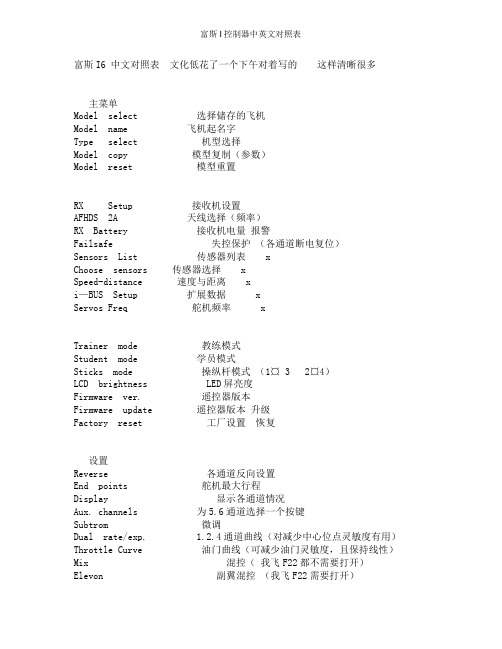
富斯I6 中文对照表文化低花了一个下午对着写的这样清晰很多主菜单Model select 选择储存的飞机Model name 飞机起名字Type select 机型选择Model copy 模型复制(参数)Model reset 模型重置RX Setup 接收机设置AFHDS 2A 天线选择(频率)RX Battery 接收机电量报警Failsafe 失控保护(各通道断电复位)Sensors List 传感器列表 xChoose sensors 传感器选择 xSpeed-distance 速度与距离 xi—BUS Setup 扩展数据 xServos Freq 舵机频率 xTrainer mode 教练模式Student mode 学员模式Sticks mode 操纵杆模式(1¤ 3 2¤4)LCD brightness LED屏亮度Firmware ver. 遥控器版本Firmware update 遥控器版本升级Factory reset 工厂设置恢复设置Reverse 各通道反向设置End points 舵机最大行程Display 显示各通道情况Aux. channels 为5.6通道选择一个按键Subtrom 微调Dual rate/exp. 1.2.4通道曲线(对减少中心位点灵敏度有用)Throttle Curve 油门曲线(可减少油门灵敏度,且保持线性)Mix 混控(我飞F22都不需要打开)Elevon 副翼混控(我飞F22需要打开)V tail V型尾翼2.4混控比例Switches assign 拨动开关分配(Fly mode飞行模式,idle mode空闲模式,Thro hold油门锁定)Throttle hold 油门锁定.开关。
VEGA导波雷达82说明书

1. 在此菜单项下可以选择应用。 VEGAFLEX 82 • 4 … 20 mA/HART - 两线制
41829-ZH-130719
参数化举例 其它步骤
快速启动
2. 在菜单项 "介质 - 介电常数"中,您可以定义介质类型 (介质)。 3. 请在菜单项 "最小调整" 和 "最大调整" 中进行调整。
3 产品简介 3.1 结构....................................................................................................................................................... 9 3.2 工作方式.............................................................................................................................................10 3.3 包装、运输和仓储............................................................................................................................10 3.4 附件与备件.........................................................................................................................................11
小型压力开关EA-BK

小型压力开关EA-BK
品牌:北方华瑞
型号:EA-BK
小型压力开关EA-BK是专门设计用来承受持久负荷用途。
此开关经工厂设定但可现场调节。
其特点是具有能和各种液体兼容的Kapton(聚酰亚胺)膜片,包括Metri-Pack(标准米制)连接器在内的各种密封接线端子的各种连接结构。
其卓越的设计优点是结构耐久,体积小及设定点稳定。
系列号EA-BK
空气、机油、变速器油、喷气燃料及其他类似碳氢工作介质
化合物
压力设定点工厂设定从0.5PSI至150PSI
最大工作压力
对于0.5-24PSI设定点范围:150PSI
对于2.5-150PSI设定点范围:1250PSI 耐压500PSI
破裂压力
对于0.5-24PSI设定点范围:750PSI
对于25-150PSI设定点范围:1250PSI 温度范围-40℃至120℃
开关类型直接动作簧片触点
电气性能阻性负载:15 AMP-6 VDC
8 AMP-12 VDC
4 AMP-24 VDC 感性负载: 1 AMP-120 VAC
0.5 AMP-240 VAC
接线端子#8-32 螺钉, 1/4"插片, Metri-Pack接插件接口1/8-27 NPT外螺纹
材料触点:镀金银合金
底座:黄铜
罩盖:玻璃纤维加强聚脂膜片:聚酰亚胺膜片
可选项电镀钢铁,塑料或不锈钢底座;各种底座连接器螺纹规格;
引线(封装密封的)
认证UL, CE。
- 1、下载文档前请自行甄别文档内容的完整性,平台不提供额外的编辑、内容补充、找答案等附加服务。
- 2、"仅部分预览"的文档,不可在线预览部分如存在完整性等问题,可反馈申请退款(可完整预览的文档不适用该条件!)。
- 3、如文档侵犯您的权益,请联系客服反馈,我们会尽快为您处理(人工客服工作时间:9:00-18:30)。
Description
• For 1/4" x 1-1/4" and 5mm x 20mm fuses • All holder bodies have the option of using 1/4" x 1-1/4" or 5mm x 20mm carriers
• Withstands 15 to 20 lbs-in torque to mounting nut when mounting fuseholder to panel • High temperature, flame retardant, Thermoplastic meets UL 94 VO
Agency Information
• UL Recognized:IZL T2, E14853• CSA Component Acceptance:Class 6225-01, File 47235
Fuseholders
HTB Panel Mount Series
Replacement Parts
Maximum Panel Thickness
Body Type
Inch Millimeters
HTB-20.307.62HTB-30.307.62HTB-40.125 3.18HTB-50.125 3.18HTB-60.307.62HTB-80.125 3.18HTB-9
0.125
3.18
SPECIFICATIONS
Product Current Voltage Fuse Quick Code Rating Rating Size Connect HTB-X2I 15A 250V 1/4" x 1-1/4"3/16"HTB-X4I 15A 250V 1/4" x 1-1/4"3/16"HTB-X6I 20A 250V 1/4" x 1-1/4"1/4"HTB-X8I 20A 250V 1/4" x 1-1/4"1/4"HTB-X2M 15A 250V 5mm x 20mm 3/16"HTB-X4M 15A 250V 5mm x 20mm 3/16"HTB-X6M 16A 250V 5mm x 20mm 1/4"HTB-X8M 16A
250V
5mm x 20mm 1/4"
Fuseholders
HTB Panel Mount Series
Visit us on the Web at
3601 Quantum Boulevard Boynton Beach, Florida 33426-8638
T el:+1-561-752-5000 T oll Free:+1-888-414-2645 Fax:+1-561-742-1178
This bulletin is intended to present product design solutions and technical information that will help the end user with design applications. Cooper Electronic Technologies reserves the right, without notice, to change design or construction of any products and to discontinue or limit distribution of any products. Cooper Electronic Technologies also reserves the right to change or update, without notice, any technical information contained in this bulletin. Once a product has been selected, it should be tested by the user in all possible applications.
OC-2580 5/02© Cooper Electronic Technologies 2002
PACKAGING CODE
Packaging Code
Description
Blank 10 pieces of fuseholders packed into a carton
BK
100 pieces of fuseholders packed into a cardboard shelf package。
