6013铝合金微裂纹分析
铝合金焊接接头产生裂纹特征及产生机理
(8)焊接接头的耐腐蚀性能低于母材
热处理强化铝合金(如硬铝)接头的耐腐蚀性的降低很明显,接头组织越不均匀,耐蚀性越易降低。焊缝金属的纯度或致密性也影响接头耐蚀性能。杂质较多、晶粒粗大以及脆性相析出等,耐蚀性就会明显下降,不仅产生局部表面腐蚀而且经常出现晶间腐蚀,此外对于铝合金,焊接应力的存在也是影响耐蚀性的一个重要因素。 为了提高焊接接头的耐蚀性,主要采取以下几个措施[5]:1、改善接头组织成分的不均匀性。主要是通过焊接材料使焊缝合金化,细化晶粒并防止缺陷;同时调整焊接工艺以减小热影响区,并防止过热,焊后热处理。2、消除焊接应力,如局部表面拉应力可以采用局部锤击办法来消除。3、采取保护措施,如采取阳极氧化处理或涂层等。
6063_H112铝合金板材加工裂纹产生的原因
收稿日期:2008-10-27 第一作者简介:李晓波(1973-),山东淄博人,助理工程师。
60632H112铝合金板材加工裂纹产生的原因李晓波,邵海霞,苏玉洁,郭 红,王美琪(东北轻合金有限责任公司,黑龙江,哈尔滨150060)摘要:厚度25mm 的60632H112铝合金板材,用户在加工过程中发现个别加工件存在裂纹。
根据用户提供的试样,从裂纹的外观形貌、断口的显微组织特征和扫描电镜特征等几个方面进行了系统地分析,并结合生产工艺的特点,判断出厚度为25mm 的60632H112铝合金板材裂纹是由于铸锭侧表面的偏析瘤压入所致。
对其形成机制和预防措施进行了阐述。
关键词:60632H112合金板材;裂纹;板材分层;偏析瘤中图分类号:TG 146121 文献标识码:A 文章编号:1007-7235(2009)02-0024-03C ausal analysis of the cracks in machining pieces of 60632H 112aluminium alloy platesLI X iao 2bo ,SHAO Hai 2xia ,S U Y u 2jie ,G UO hong ,WANG Mei 2qi(N ortheast Light Alloy Co.,Ltd.,H arbin 150060,China)Abstract :Several machining pieces of 60632H112plates with thickness 25mm were discovered s ome cracks in processing them by customers.Based on that the testing sam ples supplied by customers had been systematically observed in the ways as the shape of crack appearance ,and the features of their fracture and microscopic structures ,and of electronic scanning ,as well as combination with the features of the process of production ,the cracks in the plates of 60632H112with thickness 25mm have been analyzed and decided ,that is which were caused by the laminating at the sides of the plates into which the segregated building 2ups located in the sides of slabs had pressed.In addition ,the mechanism of forming the cracks and precautions to address them have been depicted.K ey w ords :60632H112alloy plate ;crack ;lamination of plate ;segregated building 2up 厚度为25mm 的60632H112铝合金板材,用户经过锯切、机械加工、表面处理后进行组装过程中发现,有个别零件存在裂纹,长度达8mm 。
铝合金焊接裂纹产生的原因和预防措施李修鹏谭长波
铝合金焊接裂纹产生的原因和预防措施李修鹏谭长波发布时间:2023-07-18T05:10:04.151Z 来源:《中国科技信息》2023年9期作者:李修鹏谭长波[导读] 铝合金是一种广泛应用于生活中的金属材料。
作为广泛应用于工业生产的金属原料,对人类社会的发展起着举足轻重的作用。
铝合金作为一种常用的机械加工材料广泛应用于生活中,很多管道和容器等都是用铝合金的金属材料制作而成。
但因其较高的导热系数和较快的冷却速度,导致其在焊接时极易产生裂纹。
要想更好地进行铝合金材料的生产和加工,就必须不断地对生产和加工工艺进行优化,从而生产出高质量的铝合金产品。
中国中车青岛四方机车车辆股份有限公司山东青岛 266111摘要:铝合金是一种广泛应用于生活中的金属材料。
作为广泛应用于工业生产的金属原料,对人类社会的发展起着举足轻重的作用。
铝合金作为一种常用的机械加工材料广泛应用于生活中,很多管道和容器等都是用铝合金的金属材料制作而成。
但因其较高的导热系数和较快的冷却速度,导致其在焊接时极易产生裂纹。
要想更好地进行铝合金材料的生产和加工,就必须不断地对生产和加工工艺进行优化,从而生产出高质量的铝合金产品。
关键词:铝合金;焊接;裂纹;原因;预防措施1.铝合金焊接裂纹产生的原因分析1.1焊接速度的影响高铝合金的焊接也受焊接速度的影响。
焊接速度对铝材的焊接膨胀量有影响,因此,在生产中,如果没有很好地控制好焊接速度,将会影响到铝材的焊接性能。
此外,由于焊接速度的差异,焊接电流的差异,也会对焊缝开裂有一定的影响。
目前的焊接速度有手动,机械,以及人机共同操控三种方式。
在需要高精度加工的中小型企业中,多采用手动方式。
机械操作适合于大批量定量生产的机械式作业,而当前的人机共同操控方式也较为普遍。
该模型集手工作业与机器作业的优势于一体,便于操作人员对施工工艺的控制。
1.2焊接工艺参数的影响在铝合金产品的生产与加工过程中,焊接过程也会对其造成一定的影响,特别是在使用不同型号的铝合金加工与加工设备时。
关于铝合金焊接裂纹产生的原因和预防的探讨

关于铝合金焊接裂纹产生的原因和预防的探讨摘要:铝合金材料作为一种具有较强的物理特性和力学性能的材料,常应用于工业制造和生产生活,在工业经济发展中起到了重要的作用。
随着轨道列车行业对铝合金焊接件的需求日益增加,使铝合金的焊接性研究也逐步深入。
由于铝合金的导热系数以及冷却速度等特性,使得铝合金焊接过程中容易出现裂纹。
本文分析铝合金焊接裂纹产生的原因和预防措施,通过分析、提出解决的措施有效的降低铝合金的焊接裂纹情况的出现。
关键词:铝合金;焊接;裂纹;原因;预防措施一、铝合金焊接裂纹产生的原因分析1.1金属结构的因素由于铝合金材料在焊接的过程中,容易出现裂纹的现象,因此首先要考虑的是改变金属材料的结构,通过改变金属结构的材料成分,都能够起到积极的影响。
由于金属结构的影响,会导致铝合金焊接中出现的热裂纹,需要进行材料金属特性的改变。
1.2焊接工艺参数的影响焊接工艺参数也会对铝合金的金属生产制造产生影响,尤其是当前铝合金金属制造中各种自动化焊接设备需要大量人工参与,这样就会导致焊接工艺的参数的不稳定,在生产过程中还会受到温度、湿度及粉尘等外部因素的影响,都会对焊接工艺参数造成干扰。
1.3焊接速度的影响焊接速度同样会影响铝合金的焊接,由于焊接速度会影响到铝合金的焊接的膨胀量,对于在制造过程中,焊接速度的不稳定,就会对铝合金的焊接接头成型造成影响,同时焊接速度形成的不同的焊接电流,都会成为铝合金的焊接裂纹产生的因素之一[1]。
当前焊接的速度控制分为人工操作和机械操作以及人机共同操控三种形式,人工操作的形式多见于对于加工精度要求高以及中小企业的操作中,机械操作适合大规模的量化生产,当前的人机共同操作的模式也是十分常见,这种模式集合了人工操作和机械操作的优点,同时能够方便操作者实施控制工艺的进程,选择不同的形式,都会对焊接速度造成影响。
1.4 材料的清洁度因素由于在运输、仓储以及加工的过程中,铝合金的焊接材料都会受到不同程度的污染,会对材料的表面受到影响,这样就影响到了材料的清洁度。
铝合金加工裂纹形成原因及解决措施
铝合金加工裂纹形成原因及解决措施摘要:铝合金锻件在加工过程中因种种原因会出现形式多样的裂纹,有的裂纹较深,肉眼即可辨别,有的裂纹较浅,通过检测方法可进行辨别。
在一些高精度、高可靠性的航空航天产品中,有裂纹的零件无法进行使用,成为废品,造成材料浪费,也增加了生产成本。
本文通过检测方法分析裂纹形成原因,选取有效方法进行加工,避免裂纹的产生,提高零件的合格率,提高产品的可靠性,对产品的研发生产具有重要的意义。
关键词:锻件;裂纹;检测1 背景随着航空航天事业的发展,对产品的可靠性和敏捷性也提出了更高的要求,因此,大部分航天产品都提出了轻量化要求,轻量化不仅可以提升运力、降低能耗,还能减少成本,带来直接的经济利润。
因此,在零件轻量化方向,选用较高的比强度材料,能大幅度减小结构体本身的重量。
铝合金凭借密度小、比强度高、易加工成形、耐腐蚀性强等优点,被广泛应用与航空航天中。
2 铝合金裂纹及检测2.1铝合金加工铝合金进行加工前,需对铝合金进行强化处理,通过锻造消除材料在冶炼过程中产生的疏松等缺陷,优化微观结构,提升材料的强度和刚度,并保持不错的材料韧性,锻造后需进行热处理,消除工件的内应力,并进行超声波探伤,确保工件内部无裂纹等缺陷。
之后选用合格的铝合金锻件分别采用电火花线切割工艺和普铣工艺对锻件进行粗加工,去除零件外多余材料,之后再选用相同的工艺对工件进行精加工,最终得到合格零件。
2.2裂纹宏观分析通过对比两种不同工艺方法加工得到的零件,结果如下图1所示,从图中可以看出,采用电火花线切割方式得到零件切割路径上会有大小不一的锯齿状裂纹,有些裂纹甚至贯穿整个薄壁,而选用普铣加工的产品,表面光滑,无明显裂纹。
图2.零件裂纹示意图2.3裂纹渗透探伤分析在肉眼下,我们无法清晰的看出裂纹的大小与形状,需对工件进行无损探伤。
工件无损探伤的方法较多,分别有射线探伤方法、超声波探伤方法、磁粉探伤方法、涡流探伤方法和渗透探伤方法等,其中渗透探伤方法是用一种带色或带有荧光的、渗透性很强的液体,涂覆与待探工件的表面,利用毛细现象将表面的液体渗透至裂纹根部,然后将表面的渗透液洗去,在荧光灯的照射下对裂纹进行查看,由于裂纹很窄,毛细现象作用显著,会在裂纹处显示出较粗的实线。
铝板裂纹特征及产生机理分析
铝板裂纹特征及产生机理分析虽然已经应用铝及其合金焊成许多重要产品,但实际焊接生产中并不是没有困难,主要的问题有:焊缝中的气\孔、焊接热裂纹、接头“等强性”等。
由于铝及其合金的化学活泼性很强,表面极易形成氧化膜,且多具有难熔性质(如Al2O3的熔点为2050℃,MgO 熔点为2500℃),加之铝及其合金导热性强,焊接时容易造成不熔合现象。
由于氧化膜密度同铝的密度极其接近,所以也容易成为焊缝金属中夹杂物。
同时,氧化膜(特别是有MgO 存在的,不很致密的氧化膜)可以吸收较多水分而常常成为焊缝气孔的重要原因之一。
此外,铝及其合金的线胀系数大,导热性又强,焊接时容易产生翘曲变形。
这些也都是焊接生产中颇感困难的问题。
下面,对在试验过程中产生比较严重的裂纹进行深入的分析。
1铝合金焊接接头中的裂纹及其特征在铝合金焊接过程中,由于材料的种类、性质和焊接结构的不同,焊接接头中可以出现各种裂纹,裂纹的形态和分布特征都很复杂,根据其产生的部位可分为以下两种裂纹形式:(1)焊缝金属中的裂纹:纵向裂纹、横向裂纹、弧坑裂纹、发状或弧状裂纹、焊根裂纹和显微裂纹(尤其在多层焊时)。
(2)热影响区的裂纹:焊趾裂纹、层状裂纹和熔合线附近的显微热裂纹。
按裂纹产生的温度区间分为热裂纹和冷裂纹,热裂纹是在焊接时高温下产生的,它主要是由晶界上的合金元素偏析或低熔点物质的存在所引起的。
根据所焊金属的材料不同,产生热裂纹的形态、温度区间和主要原因也各有不同,热裂纹又可分为结晶裂纹、液化裂纹和多边化裂纹3类。
热裂纹中主要产生结晶裂纹,它是在焊缝结晶过程中,在固相线附近,由于凝固金属的收缩,残余液体金属不足不能及时填充,在凝固收缩应力或外力的作用下发生沿晶开裂,这种裂纹主要产生在含杂质较多的碳钢、低合金钢焊缝和某些铝合金;液化裂纹是在热影响区中被加热到高温的晶界凝固时的收缩应力作用下产生的。
在试验过程中发现,当填充材料表面清理不够充分时,焊接后焊缝中仍存在较多的夹杂和少量的气孔。
铝合金焊接裂纹产生的原因和预防措施
铝合金焊接裂纹产生的原因和预防措施摘要:我国是全球最大的钢铁和铝材生产国。
铝合金是现代工业生产中不可缺少的原材料,在工业生产中起着举足轻重的作用。
铝合金是一种广泛应用于生活中的金属,也是一种广泛应用于工业生产的金属原料,对人类社会的发展起着举足轻重的作用。
铝合金作为一种常用的机械加工材料广泛应用于生活中,很多管道和容器等都是用铝合金制作而成。
但因其较高的导热系数和较快的冷却速率,导致其在焊接时极易产生裂纹。
要想更好地进行铝合金的生产和加工,就必须不断地对生产和加工工艺进行优化,从而生产出高质量的铝合金产品。
关键词:铝合金;焊接裂纹;原因措施1铝合金焊缝裂纹类型与成因分析铝合金焊接时,因其材质、性能及焊接组织的差异,会产生多种形式的裂纹。
裂纹不仅会影响到结构的强度,还会导致结构的突然失效。
所以,在焊接的时候,是不能有裂缝的。
1.1热裂机理分析为了对铝合金焊接热裂纹的形成机制进行精确的研究,将其焊接熔池的结晶过程划分为3个阶段。
①液固阶段。
在熔化过程中,由于熔化温度较高,在熔化过程中,只有少量的晶核。
在较低的温度下,较长的降温时间下,结晶核不断生长,形成新的结晶核。
但在此过程中,液相所占比例很大,而且颗粒间并无直接接触,因此,不会影响尚未凝固的液态铝的自由流动。
这样的话,即便是在拉应力的作用下,这些裂口也会很快被液态金属所填充。
所以,在液固相中,几乎没有开裂的可能。
②固液阶段。
随着熔池的不断结晶,熔池中的固体越来越多,之前的结晶也越来越大,等到温度降到一定程度后,这些结晶便会开始接触,然后相互挤压。
此时,液体铝的流动受阻,也就意味着,液体铝变成了固体和液体。
此时,因为只有少量的液态铝,其自身的形变可以得到很大的发展,残余的液相在晶粒之间难以流动,甚至不能填补因拉应力而形成的细小空隙。
在这种情况下,只要有一点点的张应力,就会出现裂缝。
所以,这一阶段也被称为“脆温度区”。
③完全凝固阶段。
熔池中的金属完全固化后,焊接接头在受拉状态下仍具有很高的力学性能,因此,焊接接头断裂的概率很低。
铝合金部件焊接接头裂纹分析
铝合金部件焊接接头裂纹分析发布时间:2022-08-28T07:12:09.149Z 来源:《科学与技术》2022年4月第8期作者:卢小浪[导读] 本文以实际工件设计结构和焊接工艺为依据,探讨分析了铝合金部件焊接接头点焊工艺完成后发生裂纹问题的主要影响因素卢小浪贵州航天乌江机电设备有限责任公司563003【摘要】本文以实际工件设计结构和焊接工艺为依据,探讨分析了铝合金部件焊接接头点焊工艺完成后发生裂纹问题的主要影响因素,从多角度全年考虑分析,对铝合金部件焊接接头纹裂产生的因素影响进行逐一排除。
其研究结果显示,造成铝合金部件焊接接头部位出现裂纹的主要因素是工件结构设计的强度较弱;而次要因素主要是:焊接的热能输入过高,进而造成了焊接热应力的增大,诱发了铝合金部件焊接接头裂纹现象的产生。
以问题为导向,提出了改进设计结构、优化焊接参数的措施手段,有效的解决了铝合金接地端子部件焊接裂纹问题。
【关键词】铝合金;焊接接头裂纹;工艺改进措施某车辆车型在进行制造生产过程中,发现在接地端子与型材处角焊缝连接部位出现了裂纹问题。
基于此,本文针对造成铝合金部件焊接接头发生裂纹现象的主要原因进行综合性、全面分析,对造成裂纹产生的主要和次要因素进行明确,以问题问导向,提出工艺操作优化策略,进而消除车辆铝合金接地端子部件焊接裂纹问题,保障车辆生产的整体质量。
1、实验材料与方法1.1 实验材料为确保实验结果的精准性,本实验采取了与实验车型一致的工件制造材料,在接头焊接工艺和形式上,也是与所选取案例车型一致。
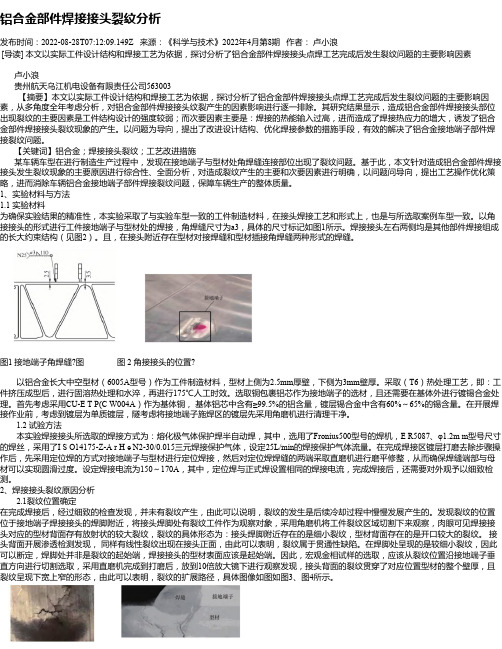
以角接接头的形式进行工件接地端子与型材处的焊接,角焊缝尺寸为a3,具体的尺寸标记如图1所示。
焊接接头左右两侧均是其他部件焊接组成的长大约束结构(见图2)。
且,在接头附近存在型材对接焊缝和型材插接角焊缝两种形式的焊缝。
图1 接地端子角焊缝?图图 2 角接接头的位置?以铝合金长大中空型材(6005A型号)作为工件制造材料,型材上侧为2.5mm厚壁,下侧为3mm壁厚。
铝合金制造业中常见的裂纹缺陷 黄有广
铝合金制造业中常见的裂纹缺陷黄有广摘要:近 40 年来,由于焊接技术的进步,高效率和高性能的焊接方法得到了推广,铝及铝合金在车辆、船舶、建筑、桥梁、化工机械、低温工程和宇航工业等各种结构方面被广泛应用,由于材料本身的特殊性,也给焊接工人带来了较大的困难,除了要掌握铝合金的焊接技术,还要注意避免在焊接过程中出现的焊接缺陷。
如:裂纹、气孔、未融合、咬边等等。
他们的存在不仅影响了焊接强度,更是为应用安全埋下了隐患。
关键词:铝合金制造业;裂纹缺陷;焊缝裂纹焊接缺陷分为工艺缺陷和设计缺陷两部分。
工艺缺陷主要受生产中的人、机、料、法、环、测六大因素影响,如裂纹、气孔、未融合、尺寸偏差等;设计缺陷是指结构产生的缺陷,如由于焊缝过密、交叉过多、材料匹配不良导致的裂纹、未融合等。
在这里我们重点介绍裂纹缺陷。
1裂纹缺陷裂纹通常分为焊缝裂纹和母材裂纹。
1.1焊缝裂纹1.1.1焊缝裂纹产生的过程焊缝裂纹也叫热裂纹,通常发生在焊接完成后,在焊缝纵向中间部位开裂。
目前关于焊接热裂纹理论,国内外认为较完善的是普洛霍洛夫理论。
概括地讲,该理论认为结晶裂纹的产生与否主要取决于以下3方面:脆性温度区间的大小;在此温度区间内合金所具有的延性以及在脆性温度区间金属的变形率大小。
通常人们将脆性温度区间的大小及在此温度区间内具有的延性值称之为产生焊接裂纹的冶金因素,而把脆性温度区间内金属的变形率大小称之为力学因素。
在焊接过程中,焊接接头的冶金因素和力学因素有着较为密切的联系,其作用归结为强化金属联系与弱化金属联系。
如果在冷却时,焊接接头金属中正在建立强度联系,在一定刚性约束条件下能够顺从的应变,当焊缝余近焊缝区金属能够承受外加约束应力与内在的残余应力的作用时,焊接接头的金属裂纹敏感性低,裂纹就不容易产生,反之,当承受不住应力作用时,金属中的强度连接容易中断,就容易产生裂纹。
其次,在焊接过程中,随着温度的降低与冷却速度的变化,冶金因素和力学因素也都随之变化,在不同的温度区间对焊接接头金属的强度联系作用各不相同,如果结晶温度区间大,固相线温度低,在晶粒间残存的低熔液态金属处更容易引起应力集中,导致固相金属产生裂纹;同样,随着温度降低,如果收缩量大,特别是在快速冷却条件下,当收缩应变速率高,应力应变状态比较苛刻时也容易产生裂纹。
铝合金型材的断裂失效表征及结构验证
铝合金型材的断裂失效表征及结构验证铝合金型材在现代工业中被广泛应用,然而型材的断裂失效可能会导致严重事故,因此需要开展相关的研究。
本文将讨论铝合金型材的断裂失效表征以及结构验证。
首先,铝合金型材的断裂失效可以通过断口形貌表征。
根据断口形貌可以得到断裂机理、载荷、应力集中位置等信息。
传统上,铝合金型材的断口形貌可以分为韧窝形和脆窝形两种,其中韧窝形属于延性断裂,一般是由于长时间的应力作用导致的断裂。
而脆窝形属于脆性断裂,通常是由于在高应力条件下的瞬间断裂或者疲劳断裂。
近年来,随着断口表征技术的进步,如扫描电镜、X射线衍射等,铝合金型材断口形貌表征的精度和准确性得到了进一步提高。
其次,铝合金型材的结构验证可以通过应力分析和实验验证两种方式。
应力分析是铝合金型材结构设计和性能改进中必不可少的步骤。
通过有限元分析和材料塑性流动分析等方法可以预测铝合金型材在载荷下的响应和损伤行为。
实验验证是验证应力分析结果的重要手段,也是研究铝合金型材断裂失效机理的途径之一。
常用的实验方法包括拉伸试验、压缩试验、扭转试验、冲击试验等。
通过实验验证可以得到真实的断裂模式、最大载荷、断裂强度、断裂韧度等参数,进一步提高应力分析的准确性。
最后,铝合金型材的断裂失效可以通过材料质量控制和结构设计优化来预防和避免。
在材料质量控制方面,需要严格遵循相关标准和要求,对铝合金型材的成分、结晶度、晶粒尺寸等进行控制和监测。
在结构设计方面,应注重载荷分配均衡、应力集中缓解、材料应力性能优化等。
同时,可以借鉴非传统的结构材料和设计思路,如纳米结构材料、天然材料、仿生设计等,来提高铝合金型材的性能和韧性。
综上所述,铝合金型材的断裂失效是工业生产中不可避免的问题,因此需要开展相关的研究。
通过断口形貌表征、应力分析和实验验证、材料质量控制和结构设计优化等方法,可以预防和避免铝合金型材的断裂失效,提高铝合金型材的使用寿命和安全性。
铝合金焊接接头产生裂纹特征及产生机理分析
铝合金焊接接头产生裂纹特征及产生机理分析近40 年来,由于焊接技术的进步,高效率和高性能的焊接方法得到了推广,铝及铝合金在车辆、船舶、建筑、桥梁、化工机械、低温工程和宇航工业等各种结构方面的应用在不断扩大,但国产化的铝合金和铝合金焊接材料均还存在着一定的差距。
对铝合金焊接接头产生裂纹的特征及产生机理进行了分析,提出了几点防范措施。
标签:铝合金;焊接接头;裂纹;机理虽然已经应用铝及其合金焊成许多重要产品,但实际焊接生产中并不是没有困难,主要的问题有:焊缝中的气孔、焊接热裂纹、接头“等强性”等。
由于铝及其合金的化学活泼性很强,表面极易形成氧化膜,且多具有难熔性质(如Al2O3的熔点为2050℃,MgO 熔点为2500℃),加之铝及其合金导热性强,焊接时容易造成不熔合现象。
由于氧化膜密度同铝的密度极其接近,所以也容易成为焊缝金属中夹杂物。
同时,氧化膜(特别是有MgO 存在的,不很致密的氧化膜)可以吸收较多水分而常常成为焊缝气孔的重要原因之一。
此外,铝及其合金的线胀系数大,导热性又强,焊接时容易产生翘曲变形。
这些也都是焊接生产中颇感困难的问题。
下面,对在试验过程中产生比较严重的裂纹进行深入的分析。
1铝合金焊接接头中的裂纹及其特征在铝合金焊接过程中,由于材料的种类、性质和焊接结构的不同,焊接接头中可以出现各种裂纹,裂纹的形态和分布特征都很复杂,根据其产生的部位可分为以下两种裂纹形式:(1)焊缝金属中的裂纹:纵向裂纹、横向裂纹、弧坑裂纹、发状或弧状裂纹、焊根裂纹和显微裂纹(尤其在多层焊时)。
(2)热影响区的裂纹:焊趾裂纹、层状裂纹和熔合线附近的显微热裂纹。
按裂纹产生的温度区间分为热裂纹和冷裂纹,热裂纹是在焊接时高温下产生的,它主要是由晶界上的合金元素偏析或低熔点物质的存在所引起的。
根据所焊金属的材料不同,产生热裂纹的形态、温度区间和主要原因也各有不同,热裂纹又可分为结晶裂纹、液化裂纹和多边化裂纹3类。
热裂纹中主要产生结晶裂纹,它是在焊缝结晶过程中,在固相线附近,由于凝固金属的收缩,残余液体金属不足不能及时填充,在凝固收缩应力或外力的作用下发生沿晶开裂,这种裂纹主要产生在含杂质较多的碳钢、低合金钢焊缝和某些铝合金;液化裂纹是在热影响区中被加热到高温的晶界凝固时的收缩应力作用下产生的。
大塑性变形(SPD)超细晶6013铝合金后时效特性及其微观结构表征
大塑性变形(SPD)超细晶6013铝合金后时效特性及其微观结构表征近年来,随着中国工业化的发展,交通、电子信息等行业对于铝合金材料的需求呈上升的趋势。
其中,汽车轻量化是铝合金在工业生产上最为广泛的应用。
另外,研究高强度高韧性的铝合金新材料,以满足航空航天、兵器等军事工业的需要也是铝合金未来发展的主要方向。
大塑性变形(SPD)技术中的等通道转角挤压技术(ECAP)可以有效地制备超细晶材料,进而显著地提高6000系铝合金的力学性能,被认为是制备块状超细晶材料极具前景的方法。
但是仅通过SPD技术并不能完全发挥6000系铝合金的强化潜力,因此,将SPD技术与时效处理相结合,进一步研究ECAP后时效处理对6000系铝合金性能的影响具有十分重要的意义。
本文以6013(Al-Mg-Si-Cu)铝合金为研究对象,对不同室温ECAP道次的试样进行后时效处理,并选用显微硬度实验、拉伸实验和电导率实验来表征其性能。
并通过差示扫描量热法(DSC)、X射线衍射(XRD)、扫描电子显微镜(SEM)和透射电子显微镜(TEM)分析6013铝合金经ECAP后时效处理后材料的微观结构变化,探讨微观结构对性能的影响,并进一步对其强韧化机制变化作出预测。
所得结果总结如下:(1)DSC分析表明,室温一道次ECAP试样在110℃下进行后时效时,析出相主要为GP区,在191℃下时效时,有β″相出现。
室温二道次试样在两种温度下进行后时效时,析出相主要为大量的GP区和少量的β″相,室温三道次试样在两种温度的后时效过程中,析出相主要为大量的GP区和β″相以及少量的β′相。
(2)XRD实验结果证实,ECAP道次的增加提高了材料在后时效过程中析出相出现的速度和数量。
同道次条件下,后时效温度的提高会加速析出相出现的产生。
同时效时间条件下,随ECAP道次的增加,同道次材料在不同时效温度下晶粒尺寸差距逐渐降低。
高温时效在加速应变降低的同时也在加剧应变降低的程度。
6013铝合金动态压缩变形行为研究

学校代号***** 学号S********* 分类号TG146.2 密级公开硕士学位论文6013铝合金动态压缩变形行为研究学位申请人姓名唐徐培养单位机械与运载工程学院导师姓名及职称李落星教授学科专业机械工程研究方向汽车轻量化论文提交日期2018年 4 月23 日学校代号:10532学号:S150200243密级:公开湖南大学硕士学位论文6013铝合金动态压缩变形行为研究学位申请人姓名:唐徐导师姓名及职称:李落星教授培养单位:机械与运载工程学院专业名称:机械工程论文提交日期:2018年 4 月23 日论文答辩日期:2018年 5 月26 日答辩委员会主席:金湘中教授Dynamic Compression Deformation Behavior of 6013 AluminumAlloybyTANG XuB. E. (Hunan University) 2015A thesis submitted in partial satisfaction of therequirements for the degree ofMaster of engineeringinMechanical engineeringin theGraduate SchoolofHunan UniversitySupervisorProfessor LI LuoxingMay, 2018湖南大学学位论文原创性声明本人郑重声明:所呈交的论文是本人在导师的指导下独立进行研究所取得的研究成果。
除了文中特别加以标注引用的内容外,本论文不包含任何其他个人或集体已经发表或撰写的成果作品。
对本文的研究做出重要贡献的个人和集体,均已在文中以明确方式标明。
本人完全意识到本声明的法律后果由本人承担。
作者签名:日期:年月日学位论文版权使用授权书本学位论文作者完全了解学校有关保留、使用学位论文的规定,同意学校保留并向国家有关部门或机构送交论文的复印件和电子版,允许论文被查阅和借阅。
铝合金产品检验裂纹的方法__概述说明
铝合金产品检验裂纹的方法概述说明1. 引言1.1 概述铝合金作为一种常用的材料,广泛应用于各行各业。
然而,在铝合金产品的生产过程中,裂纹的出现是一个普遍存在的问题。
裂纹如果未能及时检测和控制,将严重影响产品的质量和性能,甚至引发安全隐患。
因此,对于铝合金产品进行有效的裂纹检验是非常重要的。
本文将介绍铝合金产品检验裂纹的方法,并对传统方法和现代方法进行对比和评价。
同时,还将详细讲解检验裂纹的一般流程及步骤,并解释判定标准和结果处理方式。
最后,通过典型案例分析与实际应用探讨,展示不同策略和方法在铝合金产品裂纹检测中的有效性和适用性。
1.2 文章结构本文共分为五个部分:引言、铝合金产品检验裂纹的方法、检验裂纹的一般流程及步骤详解、典型案例分析与实际应用探讨以及结论与展望。
在“铝合金产品检验裂纹的方法”部分,我们将介绍传统方法和现代方法,并对它们的优缺点进行对比和评价,帮助读者了解不同方法的特点和适用性。
在“检验裂纹的一般流程及步骤详解”部分,将详细介绍裂纹检查前的准备工作和设备要求,并阐述裂纹检查技术的应用步骤。
同时,我们还会讨论判定标准和结果处理方式,确保有效地识别和处理裂纹。
在“典型案例分析与实际应用探讨”部分,我们将提供三个具体案例来展示铝合金产品裂纹检测中的策略选择、方法比较以及自动化裂纹检测系统对质量提升的情况说明。
通过真实案例的分析,读者可以更好地理解并应用所学知识。
在“结论与展望”部分,我们将对全文进行总结,并对未来铝合金产品检验裂纹的发展方向和改进探讨。
这将为相关领域的研究人员提供一些启示和建议。
1.3 目的本文旨在系统介绍铝合金产品检验裂纹的方法以及相关技术。
通过本文的阐述和案例分析,读者可以全面了解不同方法的优缺点、裂纹检查的流程和步骤,以及如何应对不同情况下的裂纹检测需求。
同时,本文还将展望未来铝合金产品检验裂纹的发展方向,为改进和完善相关技术提供参考依据。
2. 铝合金产品检验裂纹的方法:铝合金产品是一种常见的结构材料,广泛应用于航空航天、汽车制造和建筑等领域。
铝合金压铸产品不良认识和分析
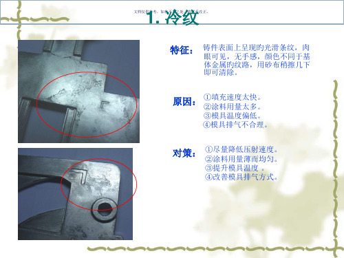
7. 变形 文档仅供参考,如有不当之处,请联系改正。
特征: 铸件几何形状与设计要求不符
原因: ①铸件构造设计不良,引起不均匀旳收缩。
②开模过早,铸件刚性不够。 ③铸件斜度太小。 ④取置铸件旳操作不当。 ⑤推杆位置布置不当。 ⑥堆放不合理或清除浇口措施不当。
对策: ①改善铸件构造,使壁厚均匀。
②拟定最佳开模时间,加强铸件刚性。 ③放大铸造斜度。 ④取放铸件应小心轻取轻放。 ⑤改善推杆位置,使其合理分布。 ⑥铸件堆放应用专用箱,清除浇口措施应 恰当。 ⑦有旳变形铸件可经整形消除。
3. 气泡 文档仅供参考,如有不当之处,请联系改正。
特征: 铸件表皮下,汇集气体鼓胀所形成旳泡。
①模具温度、合金熔炼温度太高。
原因:②填充速度太高,金属液流卷入气体过多。
③涂料发气量大,用量过多,使挥发气体 被包在铸件表层。
④排气不畅。 ⑤开模过早。
对策 ①降低模具、合金溶液至工作温度。
②降低压射速度,防止涡流包气。 ③选用发气量小旳涂料,用量薄而均匀,
模板产生抖动。 ②压射冲头与压室配合不好,在压射中 迈进速度不平稳。 ③浇注系统设计不当。
对策:①加强模具刚度,紧固模具部件。
②调整压射冲头与压射,确保配合良好。 ③合理设计内浇口
8. 碰、压伤 文档仅供参考,如有不当之处,请联系改正。
特征: 铸件表面因外力作用而造成旳伤痕。
原因:
①冲剪、整平、铆合时产品与治具贴合面 有异物造成压伤。
②去浇口、清理和搬运流转过程中不小心
碰伤。
对策: ①针对产品与治具表面定时清理,治具表
面尽量大旳避空。
②清理铸件要小心,存储及搬运铸件,不 应堆叠或相互撞击。
属液进入型腔产生旋涡。 ②浇道形状设计不良。 ③排气不畅。 ④涂料过多,填充前未燃尽。 ⑤压铸成型条件不合理。 ⑥机械加工余量太大。
铝冷轧加工表面的微裂纹分析
铝冷轧加工表面的微裂纹分析张朝辉;刘思思;孙跃涛【摘要】微乳液润滑的铝冷轧过程中常会在铝合金表面出现与轧制方向垂直的规则微裂纹.规则裂纹的产生是由于新生金属表层氧化膜与体相金属具有不同的拉伸性能.考虑氧化膜拉伸强度极限与其厚度、体相材料的屈服极限及边界润滑的摩擦系数等因素,建立了理论模型,预测微裂纹分布间隔.通过对两种不同轧机冷轧加工后的铝合金表面分析,验证了分析模型的正确性,研究结果将对铝冷轧特性的分析起到促进作用.%Regularly distributed micro-cracks which are perpendicular to the rolling direction are usually formed on the surface of aluminium sheet during cold rolling lubricated with micro emulsions. Experiments show that micro-cracks occur after cold rolling process, which is attributed to various parameters, for instance, the thin oxide film formed at the sheet surface. The micro-crack spacing thus becomes an important parameter that should deserve more attention. By taking into consideration of the oxide fracture process, the aspect ratio of these micro-cracks is analyzed theoretically. The good agreement between the observations and the theoretical predictions validates these analyses. This approach can shed some new lights on the mechanical process of aluminium sheet during cold rolling.【期刊名称】《北京交通大学学报》【年(卷),期】2012(036)001【总页数】4页(P108-111)【关键词】摩擦学;冷轧;微裂纹;微乳液;铝板【作者】张朝辉;刘思思;孙跃涛【作者单位】北京交通大学机械与电子控制工程学院,北京 100044;北京交通大学机械与电子控制工程学院,北京 100044;北京交通大学机械与电子控制工程学院,北京 100044【正文语种】中文【中图分类】TH117铝合金板材广泛应用于汽车、船体和空间器等制造业中代替钢板以减轻重量.冷轧加工是获得优质铝板的有效手段.正确润滑是冷轧加工中保证加工质量和效率的重要手段.摩擦与冷轧铝材表面质量和滚子的表面粗糙度密切相关[1-2],一般而言,平均摩擦系数还依赖于很多其他因素,其中速度是关键因素[3].在金属冷轧过程中常用摩擦模型通过在线或离线控制来增加产量、改善表面质量.Sutcliffe等[4-5]测量了混合润滑状态下冷轧表面的粗糙度变化,发现短波分量存在于冷轧件表面,体现了干摩擦的一种镜像效果,由此提出一个二维摩擦模型[6].Cambiella等[7]发现金属表面与乳化剂分子间的相互作用在乳化液润滑中起到关键作用.当黏度和滑动速度足够时,嵌入微坑的润滑剂可以被吸入到界面间,因而轧制过程至少存在3个机理:①入口区油的流体动力作用;②由于滑动速度引起的微坑内流体动力效应;③存在于分离微坑内的流体产生的静力效应.在轧制金属和合金时会形成某种形式的迁移层(transfer layer),比如冷轧中轧辊表面常有颜色的改变[8].它的出现常与润滑剂有关(平均膜厚和添加剂的效果),也与被轧制的合金特性相关.这是因为硬质迁移层研磨粒子的存在,或者是脆性或韧性氧化层的存在所导致的[9].这种迁移层也出现在铝的冷轧中,比如Chambat等通过检查用过的冷轧润滑剂,发现了铝冷轧形成的铝和边界润滑添加物的化学反应物[10],这是由于表面氧化层断裂和新生成金属表层暴露在空气中(容易再次被氧化),当新生成的铝金属暴露在空气中时,其氧化的速度很快,而氧化表层性质和体相层不同,所以会萌生出微裂纹.在铝冷轧加工中常用微乳液来提供润滑和冷却能力.微乳液主要成分有油、水和乳化剂.在大多数金属加工中常用的微乳化液是水包油(oil-in-water,O/W)型,即油为分散相,水为连续相[11].乳化剂是一种表面活性剂,表面活性剂一般为具有亲水与疏水基团的有机两性分子,可溶于有机溶液和水溶液.表面活性剂通常分为阴离子、阳离子、非离子和两性离子(双电子)4大类.水基微乳液中连续相(水)的比重很大,其润滑能力取决于微乳和水的特性.由于水的黏度和黏压指数很低,微乳液润滑的铝冷轧常处于边界润滑或混合润滑状态下,冷轧件的表面就常能被加工到与光滑的轧辊一致.在铝合金的冷轧中,新生成表面迅速被氧化,表层氧化膜与体相金属(铝基体)对外加应力的响应有很大不同,因而导致了冷轧后铝表面规则微裂纹的形成.本文作者分析了微乳润滑下铝冷轧过程中微裂纹的形成特性,并建立相应的理论模型,并通过对5052铝合金板冷轧加工得到的表面进行分析,验证了分析模型.1 分析模型冷轧铝合金表面微裂纹的产生与分布特性根源是表层氧化膜与体相的性质差异.假定体相材料处在塑性状态,且不可压缩,服从塑性流动的von Mises准则,铝板外表层的氧化膜被认为无伸展性.另外,冷轧轧辊具有纵向的粗糙度,轧辊和铝板表面具有相似的自相关长度,但相互无关联.裂纹间隙决定了新生铝暴露于润滑剂中添加剂和新生铝与轧辊表面接触的方式,因而需要仔细分析.分析模型可分为两个步骤:1)微裂纹在入口区的萌生阶段.分析过程类似于Le和Sutcliffe对干摩擦工况的分析[12],其原理如图1所示.铝板的弹塑性特性引起铝板在接触前产生变形和氧化层被拉伸.假定厚度为tc的氧化层(扫描电子显微镜检测结果表明其典型值为约1 μ m)内有一微裂纹位于PP′平面,当它向前移动时,分析氧化膜内的应力发展可以预测下一个微裂纹的出现及裂纹间的间隔.当PP′接近咬合处时,由于铝板表面的弹性拉伸,氧化层内的纵向应力增大.氧化层内最大纵向应力出现于平面OO′,它距离PP′的距离为d,在此界面处剪切应力改变符号.图1 裂纹萌生分析Fig.1 Crack initiation analysis当最大应力达到氧化膜的强度极限σf时,在氧化膜内最大应力处将出现初始裂纹,这一微裂纹将在入口释放应力,当进入咬合处后应力又将增大.最大应力与前一裂纹间的相应距离即是微裂纹的间隔大小.当氧化层强度一定时,降低氧化膜厚度将减小微裂纹间隔.对氧化膜应力的分析将有助于建立微裂纹间隔与氧化膜厚度及材料特性之间的联系.2)轧辊咬合区内的裂纹阶段.如图2所示,在轧辊和铝板界面处的氧化膜碎片的长度为λ,这一长度值远小于轧辊半径,轧辊和氧化膜表面可简化为平面.作用于氧化膜上表面和下表面上的法向压力沿氧化膜碎片为常数,等于体相金属(铝材)的平面应变屈服极限应力Y.图2 体相金属的延展导致氧化膜的断裂Fig.2 Oxidation film crack due to the extension of bulk phase metal在铝和轧辊的咬合区内,底层金属(铝板)在轧制方向上塑性延展,而脆性的氧化层碎片在咬合区内的伸长可以忽略.因此,在氧化膜与底层体相之间产生相对滑移,导致产生界面上的剪切应力τi.如果氧化膜牢固结合在底层材料上,其剪切强度等于体相底层的剪切强度k(=Y/2).尽管氧化膜与基底间的中部可能有一黏结区,但由于应变的巨大差异,这一区域很小,因此在整个界面上存在滑移,其界面上剪切应力τi就等于极限值k.另外,摩擦应力τr作用在轧辊和氧化膜的上表面间,因为在入口区轧辊表面速度比铝板大,它作用在整个氧化膜碎片面上.为简单起见,考虑到微乳液润滑时润滑状态处于边界润滑状态,假定接触区的摩擦服从Coulomb摩擦定律,即有:τr=μp=μ Y,其中μ为摩擦系数.表面上牵引力在氧化膜片内引起的纵向拉伸应力为σ,如图2所示,存在一位置,在此处氧化膜与基底的速度相等,在此点处界面剪切应力τi的符号改为负方向.从两端到此中点处的长度分别用ξA和ξB表示.由氧化膜片的横向力平衡关系有注意到,中点位置为假定氧化膜平整,氧化膜内横向应力不沿厚度变化.氧化膜内最大拉伸应力σm出现在中点处,其值为当它达到氧化膜的拉伸极限σf时氧化膜将分裂为更小碎片,此时氧化膜裂纹达到临界值λc.利用式(1)~式(3),再考虑到界面应力关系τr=k=μ Y,氧化膜的最大纵横比λc/tc可以推导为式(4)表明纵横比由氧化膜的拉伸强度对体相材料的剪切屈服极限比决定.另外,式(4)还表明摩擦应力因素不突出,因为有效摩擦系数通常都远小于0.5.2 模型验证实验中轧制铝板为5052合金板,宽度为1~1.5 m,其化学组成Si,Fe,Cu,Mn,Mg,Cr,Zn,Ti的质量分数依次为0.25%,0.4%,0.1%,0.1%,2.8%,0.25%,0.1%,0.15%,其余为Al[13].轧制使用的润滑剂是微乳液,水为连续相,油为分散相以形成水包油的微乳液.最大乳液供应速率为220 L/min,出口液体压力为2 kg/mm,压下力为500~700 t.微乳液的基础油包括合成脂和矿物油及其他添加剂.实验中采用的微乳液,黏度(20℃)为2.02×10⁻⁶m2/s(质量分数为95%),轧制的总压下率为50%.实验分别在1400型和2800型轧机上进行,轧制后的5052铝合金表面的扫描电子显微镜(SEM)照片如图3(1400轧机)和图4(2800轧机)所示.从图3与图4可以看出,轧制后的铝合金表面有明显的规则裂纹,裂纹方向与轧制方向垂直.比较图3和图4的微裂纹分布还可以看出微裂纹之间的间隔几乎一致,这也表明摩擦系数(不同轧机冷轧时有不同的摩擦系数)对氧化膜的纵横比影响不大,与之前分析一致.图3 1400轧机轧制后的铝合金表面Fig.3 SEM image of aluminium alloy surface after rolling by 1400 rolling mill图4 2800轧机轧制后的铝合金表面Fig.4 SEM image of aluminium alloy surface after rolling by 2800 rolling mill3 结论1)铝合金冷轧加工表面常出现与轧制方向垂直的规则微裂纹,这主要是由于在铝合金表面形成的氧化层与体相层的性质不同造成的.氧化膜层脆而延展性差,不能承受拉应力,拉应力由裂纹释放.2)分析得出氧化层裂纹间隔与氧化膜厚度的关系由式(4)给出,即最大纵横比由氧化膜拉伸强度、体相层剪切屈服极限及摩擦系数等因素决定(由于实际有效摩擦系数远小于0.5而使得前两个因素为主要因素).3)通过对在 1400轧机和 2800轧机上冷轧5052铝合金表面的分析证实了本文结论的正确性.参考文献(References):[1]SCHEY J A.Surface roughnesseffects in metalworkinglubrication[J].Lubrication Engineering,1983(39):376-382.[2]SUN J L,LU W,SHI Q B,et al.Surface quality of cold rolling aluminium strips under lubrication condition[J].Journal of University of Science and Technology Beijing,2008,15:335-338.[3]SENG L L,LENARD J G.Study of friction in cold strip rolling[J].Journal of Engineering Material Technology,1984(106):139-146.[4]SUTCLIFFE M P F.Flattening of random rough surfaces in metal forming processes[J].Journal of Tribology,1999,121:433-440.[5]SUTCLIFFE M P F,LE H R.Measurements of surface roughness in cold metal in the mixed lubrication regime[J].STLE Tribology Transactions,2000,43:39-44.[6]LE H R,SUTCLIFFE M P F.A friction model for cold strip rolling with two-wavelength surface roughness in the“mixed” lubricationregime[J].Journal of Tribology,2003,125:670-677.[7]CAMBIELLA A,BENITO J M,PAZOS C,et al.The effect of emulsifier concentration on the lubrication properties of oil-in-wateremulsions[J].Tribology Letters,2006,22:53-65.[8]SUTCLIFFE M P F,COMBARIEU R,REPOUX M,et al.Tribology of plane strain compression tests on aluminium strip using tof-sims analysis of transfer films[J].Wear,2003(254):65-79.[9]MONTMITONNET P,DELAMARE F,RIZOULIERES B.Transfer layer and friction in cold metal strip rolling processes[J].Wear,2000(245):125-135. [10]CHAMBATF,LASHERMES M,anometallic compounds produced during aluminium cold rolling[J].LubricationTechnology,1987,43:522-527.[11]张康夫,王余高,屠伟刚,等.水基金属加工液[M].北京:化学工业出版社,2008:48-60.ZHANG Kangfu,WANG Yugao,TU Weigang,et al.Water based metal working fluid[M].Beijing:Chemical Industry Press,2008:48-60.(in Chinese) [12]LE H R,SUTCLIFFE M P F,WANG P Z,et al.Surface oxide fracture in cold aluminium rolling[J].Acta Materialia,2004,52:911-920.[13]徐帮学.铝与铝合金产品国内外最新标准及其工程应用技术全书[M].北京:银声音像出版社,2004:69-78.XU Bangxue.Pandect of the newest standard at home and abroad and engineering applied technology on aluminum and aluminum alloy[M].Beijing:Yin Sheng Audio and Video Press,2004:69-78.(in Chinese)。
铝合金部件焊接接头裂纹分析
铝合金部件焊接接头裂纹分析摘要:本文以铝合金部件焊接接头裂纹分析为研究对象,对焊接接头裂纹的形成机理、检测方法和控制技术进行了深入探讨。
通过对焊接参数、焊接材料和焊接后热处理方法的优化研究,可以降低焊接接头裂纹的发生率,提高接头的质量和可靠性。
关键词:铝合金部件;焊接;接头裂纹焊接接头是铝合金部件中最常见的连接方式之一,但是由于焊接过程中的热应力、残余应力和变形等因素,焊接接头很容易出现裂纹。
焊接接头裂纹的出现会严重影响铝合金部件的性能和安全性,因此对焊接接头裂纹的分析、检测和控制具有重要意义。
本文从焊接接头裂纹的形成机理、检测方法和控制技术等方面进行了深入探讨,旨在为焊接接头裂纹的分析和控制提供参考。
1焊接接头裂纹形成机理分析焊接接头裂纹形成机理分析是铝合金部件焊接接头裂纹分析学术论文的一个重要部分。
在这部分中,我们需要对焊接接头裂纹的形成机理进行深入的分析,以便更好地理解裂纹形成的原因和机制。
具体来说,焊接接头裂纹形成机理分析可以从以下几个方面展开:1.1焊接过程的热力学分析焊接过程是产生焊接接头裂纹的主要原因之一。
焊接过程中产生的高温和应力容易导致铝合金材料的微观组织发生变化,从而产生裂纹。
因此,我们需要进行热力学分析,了解焊接过程中的温度分布、热应力分布等参数,以便更好地理解焊接接头裂纹的形成机理。
1.2焊接接头应力分析焊接接头的应力是产生焊接接头裂纹的另一个主要原因。
焊接接头在焊接后会受到内部应力的影响,这些应力会导致接头的变形和裂纹。
因此,我们需要进行应力分析,了解焊接接头中各个部位的应力情况,以便更好地预测焊接接头裂纹的形成位置和形态。
1.3焊接接头金相组织分析铝合金部件的微观组织是决定其力学性能和耐腐蚀性能的重要因素。
焊接接头的金相组织分析可以帮助我们了解焊接接头中的晶粒结构、相组成、缺陷分布等信息,从而更好地理解焊接接头裂纹的形成机理。
综上所述,焊接接头裂纹形成机理分析是铝合金部件焊接接头裂纹分析学术论文的重要内容之一。
铝合金部件焊接接头裂纹分析_1
铝合金部件焊接接头裂纹分析发布时间:2022-09-14T03:32:46.031Z 来源:《科学与技术》2022年第30卷9期作者:刘细红代媛媛[导读] 6005A是中等强度的Al-Mg-Si系铝合金,具有良好的热挤压性和耐蚀性,被用于高速列车、地铁列车、双层列车和汽车车体所需的薄壁中空大型铝合金壁板型材以及其他工业用结构型材,欧洲大量采用6005A铝合金制造高速列车的车体。
刘细红代媛媛中车青岛四方机车车辆股份有限公司山东青岛 266111摘要:6005A是中等强度的Al-Mg-Si系铝合金,具有良好的热挤压性和耐蚀性,被用于高速列车、地铁列车、双层列车和汽车车体所需的薄壁中空大型铝合金壁板型材以及其他工业用结构型材,欧洲大量采用6005A铝合金制造高速列车的车体。
这就给车辆的电气设备提出了新的要求:若采用铜合金材料作为接地点,则铜材料如何与铝材料连接的问题不好解决;若采用铝合金材料作为接地点,则影响导电性能,且存在电化学腐蚀。
在此背景下,铜包铝复合材料接地块作为接地材料被广泛应用在铝合金车辆上。
关键词:铝合金部件;焊接接头;裂纹;措施在某车型试制生产中,接地端子与型材处角焊缝连接部位出现裂纹。
本文结合具体的焊接结构和现车生产工艺,通过对影响裂纹产生的各项因素分别进行分析,最终确定了导致裂纹产生的主要因素,并提出了避免该部位产生焊接裂纹的措施。
1试验材料及方法1.1试验材料试验采用实际工件所用的原材料,同时接头形式与实际焊接接头相同。
该焊接接头形式为角接接头。
焊接接头左右两侧均是其他部件焊接组成的长大约束结构。
该接头附近有两种焊缝:一是型材对接焊缝,焊缝形式为4V;二是型材插接角焊缝。
型材为铝合金长大中空型材,型号为6005A,内设加强筋,上侧壁厚2.5mm,下侧壁厚3mm。
T6供货状态,即挤压成形后进行固溶处理和水淬,之后再进行175℃人工时效。
接地端子材质采用铜包裹铝芯,并在铜基体外镀锡合金。
- 1、下载文档前请自行甄别文档内容的完整性,平台不提供额外的编辑、内容补充、找答案等附加服务。
- 2、"仅部分预览"的文档,不可在线预览部分如存在完整性等问题,可反馈申请退款(可完整预览的文档不适用该条件!)。
- 3、如文档侵犯您的权益,请联系客服反馈,我们会尽快为您处理(人工客服工作时间:9:00-18:30)。
Journal of Materials Processing Technology 231(2016)18–26Contents lists available at ScienceDirectJournal of Materials ProcessingTechnologyj o u r n a l h o m e p a g e :w w w.e l s e v i e r.c o m /l o c a t e /j m a t p r o t ecMicro-scale model based study of solidification cracking formation mechanism in Al fiber laser weldsXiaojie Wang a ,d ,Fenggui Lu a ,b ,∗,Hui-Ping Wang c ,∗,Zhaoxia Qu d ,Liqian Xia daShanghai Key Laboratory of Materials Laser Processing and Modification,School of Materials Science and Engineering,Shanghai Jiao Tong University,Shanghai 200240,PR China bCollaborative Innovation Center for Advanced Ship and Deep-Sea Exploration,Shanghai 200240,PR China cManufacturing System Research,GM Global R&D,Warren,MI 48090,USA dWelding and Corrosion Protection Technology Department Research Institute,Baoshan Iron &Steel Co.Ltd.,Shanghai 201900,PR Chinaa r t i c l ei n f oArticle history:Received 27September 2015Received in revised form 19November 2015Accepted 11December 2015Available online 15December 2015Keywords:Micro-scale model Solidification cracking Welding speed Pressure drop Micro structurea b s t r a c tEffect of welding speed on solidification cracking susceptibility in fiber laser welding of 6013aluminum alloy was investigated by considering both mechanical and metallurgical factors.A finite element model was developed at columnar grain scale to calculate the strain localization in the mushy zone.Based on the Rappaz-Drezet-Gremaud (RDG)criterion and study from the developed micro-scale model,the pressure drop in the inter-dendritic liquid film was used as cracking index to investigate the formation of solidification cracking.Cooling rate,solid fraction,local strain rate and microstructure characteristic resulted from different welding speeds were examined.Cracking sensitivity was shown to decrease with the increase of welding speed in the range between 2.5m/min and 3.5m/min in fiber laser welding of 6013aluminum alloy.Numerical calculations showed that mechanical tensile strain in the solid grain was in the order of magnitude of 10−4while the strain in the liquid film is in the order of magnitude of 10−2.The total pressure drop at the root of columnar grains was more than 150kPa,which was deemed as the critical pressure drop to form a crack in this study.The transverse solidification cracking was prone to initiate in the second half of mushy zone where the solid fraction was between 90%and 94%.©2015Elsevier B.V.All rights reserved.1.IntroductionAluminum alloys have been widely employed in body con-struction of automobiles and aircraft due to their outstanding mechanical properties and formability.Fusion-based welding pro-cesses such as arc welding and laser welding are commonly used in joining the Al materials.However,solidification crack,which is harmful to structural integrity,could easily exist in the welded Al joints (Kou 2003).The solidification cracking occurs in the mushy zone when insufficient amount of liquid flows back to heal the tear-ing of inter-dendritic liquid film during the material’s solidification processes (Hatami et al.,2008and Sheikhi et al.,2014).For high manufacturing productivity,welding speed is usually set to be as large as possible in practical applications.It is generally accepted in welding community that large welding speed would lead to hot cracking (Niel et al.,2013).Cicala et al.(2005),Fabregue∗Corresponding authors.E-mail addresses:Lfg119@ (F.Lu),hui-ping.wang@ (H.-P.Wang).et al.(2008a)and Tirand et al.(2013)independently investigated the effect of welding speed on hot cracking during Nd:YAG laser welding of AA6056aluminum alloy with welding speed in the range between 3m/min and 6m/min,4m/min and 6m/min,and 1.2m/min and 3.5m/min,respectively.They all observed that high welding speed resulted in high hot cracking susceptibility,which was explained by the resulted high weld pool instability,high cool-ing rate and high solidification rate.El-Batahgy and Kutsuna (2009)reported that the hot cracking started to occur in AA6061,AA5083and AA5052aluminum alloys during CO 2laser welding when the welding speed increased from 3m/min to 6m/min.Haboudou et al.(2003)showed that use of a second beam to decrease the cooling rate of molten pool would effectively prevent hot cracking.However,positive influence of welding speed on hot cracking of aluminum alloys was also reported.Chihoski (1972)indicated an improvement in weldability when increasing the welding speed to 0.8m/min in the gas tungsten arc (GTA)welding of AA2014alu-minum alloy.The high welding speed would induce a compressive loading zone at the tail of molten pool that helped suppress-ing hot cracking.Abbaschian and Lima (2003)studied the hot cracking sensitivity of Al–Cu alloy with various welding speeds/10.1016/j.jmatprotec.2015.12.0060924-0136/©2015Elsevier B.V.All rights reserved.X.Wang et al./Journal of Materials Processing Technology231(2016)18–2619 in continuous-wave CO2laser welding.With increasing weldingspeed from0.06m/min to3m/min,the cracking susceptibilityincreasedfirst and then dropped due to the refinement of porositiesand changes of liquid fraction.As discussed above,the influence of welding speed on hotcracking varies for different welding processes and at differentwelding speed.The cooling rate,solidification rate,stress state andmicrostructure characteristic all would influence the hot crack-ing susceptibility.Eskin and Katgerman(2004)stated that the hotcracking was a physical phenomenon affected jointly by thermal,mechanical and metallurgical features.Hence,a comprehensiveunderstanding of hot cracking sensitivity at different welding speedshould take into account all the factors mentioned above.Rappaz et al.(1999)proposed a hot cracking model,namedas RDG(Rappaz-Drezet-Gremaud)model,which considered theeffects of liquid feeding,permeability of microstructure,solid frac-tion and deformation of the grains on the hot cracking initiation.Wang et al.(2004)analyzed the effect of grain boundary misorien-tation on hot cracking tendency based on the RDG model.Drezetand Allehaux(2008)systematically analyzed the application ofRDG model in the prediction of hot cracking phenomenon in thewelds.Niel et al.(2013)extended the RDG model by introducingmicrostructure prediction and investigated the effect of weldingcurrent on hot cracking in the GTA welding.Sheikhi et al.(2014)used the RDG model to calculate the hot cracking sensitivity insuccessive laser weld spots considering preheating effect.In this study,the effect of welding speed on solidification crack-ing infiber laser welding of6013aluminum alloy was investigatedexperimentallyfirst.Next,a micro-scalefinite element model of acolumnar grain in mushy zone was developed which mainly inves-tigated the strain rate of grains with the existence of liquidfilm.Based on the RDG model and the corresponding pressure drop,theeffect of welding speed on hot cracking sensitivity was analyzed.Other important state variables such as cooling rate,solid fraction,stress state and microstructure characteristic were also examined.Also,the possible initiation site of solidification cracking infiberlaser welding of aluminum alloy was predicted.2.Weld solidification cracking model2.1.RDG criterionDue to large temperature gradient existing near fusion line of themolten pool in laser welding,columnar dendrite structure wouldappear near the fusion line while equiaxed grains exist in the centerof fusion zone where temperature gradient decreases(Niel et al.,2013).According to the study of Fabregue et al.(2008b),solid-ification cracking initiates near the fusion line where columnargrains exist.To investigate the formation of solidification crack-ing in columnar dendrite structure,Rappaz et al.(1999)proposedthe RDG model and deemed crack as a result betweenflow rate andthe deformation and shrinkage of columnar grains,as shown in Eq.(1):f l v l,x=−(1+ˇ)Lf s˙εdx−v Tˇf l(1)v T=V cos˛(2) where f l is the liquid fraction,v l,x is the velocity of thefluid along the x-axis which is parallel to columnar grain growth direction,ˇis the shrinkage factor,L is the mushy zone length along x-axis,f s is the solid fraction,˙εis the deformation rate of grain boundary per-pendicular to the grain growth direction,and v T is the solidification rate.Thefirst term on the right-hand side of Eq.(1)is theflow rate caused by the tensile deformation of mushy zone,and the second term on the right-hand side of Eq.(1)is theflow rate associated with the solidification shrinkage of mushy zone.Rai et al.(2008) provided the relationship between the solidification rate and the welding speed in Eq.(2),where V is the welding speed and␣is the angle between the normal of solid-liquid interface and the direction of welding velocity.The permeability of microstructure reflects the degree of microstructure in beingfilled back by liquidflow.Niel et al.(2013) defined the permeability of mushy zone in Al welds as follows:K=22180(1−f s)3f2s(3)where 2is the secondary dendrite arm spacing.Theflow rate is related to the pressure gradient in the liquid,the permeabil-ity of the mushy zone and viscosity of the liquid( )by f l v l,x=−(K/ )(dp/dx),which cited from the study of Kubo and Pehlke (1985).Substituting thisflow rate calculation into Eq.(1),the pres-sure drop in the interdendritic liquid could be calculated as follows (Rappaz et al.,1999):P=18022(1+ˇ)LE(x)f2s(1−f s)3dx+18022v Tˇ×Lf s1−f s2dx(4)In the RDG model,the interdendritic liquid pressure drop between the tip and root of the dentrite is required to ensure that adequate liquid feeding back occurs to compensate the deforma-tion and shrinkage of mushy zone.If the pressure drop reaches the critical pressure drop that a cavity forms,hot cracking initiates.Eq.(4)tells us that the solidification rate at columnar grain tip,solid fraction,deformation rate of the columnar grain,length of mushy zone and secondary dendrite arm spacing all would affect the pres-sure drop,hence the susceptibility of solidification cracking.Based on the work of Rappaz et al.(1999),shrinkage factor and viscosity were taken as0.06and0.001Pa s for Al welds,respec-tively.The secondary dendrite arm spacing 2could be obtained by experimental observation.The others,such as mushy zone length, solid fraction,solidification rate and strain rate,are taken from calculated results.2.2.Thermal-mechanical simulation of welding processWe now know that hot cracking susceptibility is affected by many factors and these factors are determined by the thermal field and mechanical deformation in the process.In order to obtain temperature and strain/stress distribution in the weld,a thermal-mechanical simulation of the laser welding process is performed.The heat conduction and the thermal-elastic-plastic deformation are considered in the simulation to calculate the tem-perature and strain/stress.To increase calculation precision t,a three dimension’s(3D)thermal-mechanical model is developed with the model size of60mm×35mm×2.5mm.In addition,the model considers temperature-dependent material physical param-eters,a volumetric heat source model,strain/stress relaxation in the weld molten pool and solidification shrinkage of the weld metal. The temperature-dependent material physical parameters of6013 aluminum alloy used in the model are given in Fig.1.Thefiber laser heat input was modeled by a cylindrical Gaussian distribution heat model,which was proposed by Kong et al.(2011). It is described by Feng(1994)to represent the stress/strain relax-ation of liquid metal in weld pool and the element rebirth method was adopted.Elements whose temperatures are over the liquidus point would be killed(zero stress)in the model,and re-birthed again as their temperatures drop to be lower than the liquidus20X.Wang et al./Journal of Materials Processing Technology231(2016)18–26Fig.1.Temperature-dependent material physical parameters of6013aluminum alloy:(a)physical parameters and(b)mechanical properties.point.The solidification shrinkage of weld metal was considered in the model by setting the reference temperature of solidified metal to liquidus point and adding the volume shrinkage of solidified metal to thermal expansion.2.3.Micro-scale model for local strain in the mushy zoneAccording to the solidification theory,David and Vitek(1989) indicated that the columnar to equiaxed transition(CET)meant that the rapid growth of equiaxed grains in the center of fusion zone inhibited the columnar grain growth.For weld microstruc-ture,the possible location of crack initiation,which is surrounded by liquidus line(T L),solidus line(T coalescence)and CET line,would be subdivided into two regions,as shown in Fig.2.Region A is defined as location where columnar grain tip connects with molten pool while Region B is defined as location where columnar grain growth is prevented by equiaxed grain.Microstructure in Region A has a similar columnar morphology as one discussed in RDG model.How-ever,the solidification rate at the columnar grain tip is zero due to the columnar to equiaxed transition in Region B,and the required flow rate in Part B is only to compensate the deformation of mushy zone if no crack forms.Prediction of the cracking susceptibility and possible initiation location requires knowledge of microstructure characteristic and local strain rate perpendicular to columnar grain.The microstruc-ture characteristic,which includes the columnar grain length, primary dendrite arm spacing of columnar grain and orientation of the grain boundary in the macroscopic frame,can be obtainedbyFig.2.The schematic of weldmicrostructure.Fig.3.Size and boundary condition of the FEM model on columnar grains. experimental observations.The local strain rate on columnar grain is calculated by a FEM model on columnar grains in this study.As shown in Fig.3,the dimensions of FEM model on columnar grains are determined by mushy zone length(L),primary den-drite arm spacing( )and thickness of liquidfilm(d).Based on the temperature distribution obtained from the thermal-mechanical welding process simulation,the mushy zone length is taken as dis-tance between liquidus point line(921K)and fusion line in Region A,and the columnar grain length is deemed as mushy zone length in Region B.Thickness of liquidfilm between columnar grains is cal-culated by Eq.(5)where is primary dendrite arm spacing and f s is the solid fraction,which is calculated with the help of Thermo-Calc software.d= (1−f s)(5) The FEM model on columnar grains consists of solid and liq-uid phases at the same time,and a continuum-level modeling is employed to calculate the local strain rate perpendicular to colum-nar grain by special treatment of liquid physical parameters.The solid and liquid physical parameters used in the model are given in Fig.1(b)and Fig.4,respectively.The mechanical properties of liquid phase were treated as one-twentieth of the solid by a trial-and-error iterative process based on the reportedfindings by Coniglio and Cross(2009)and Bordreuil and Niel(2014).Their work showed that the local strain in liquid was about102-103times of local strain in solid.The boundary condition of temperature and displacement were obtained from process simulation and linearly interpolated from the process domain to the columnar grain domain.Temper-ature along the columnar grain is used to calculate solid fraction,X.Wang et al./Journal of Materials Processing Technology231(2016)18–2621Fig.4.Temperature-dependent material physical parameters used in the FEM model on columnar grains.and the calculated local strain rate of the solid-liquid interface is adopted as the deformation rate of solids in Eq.(4).The RDG criterion simplifies the feeding back of liquidflows only along the growth direction of columnar grain.Therefore,only strain on grain boundary perpendicular to the growth direction of grain is required.Considering the orientation of columnar grain boundary in macroscopic frame,Bordreuil and Niel(2014)proposed the for-mulation for the strain perpendicular to columnar grain as follows:ε=εx sin2Â+εy cos2Â+2 xy sinÂcosÂ(6)whereεx is mechanical strain in horizontal direction,εy is mechan-ical strain in vertical direction andÂis the angle between the columnar grain direction and the welding velocity.Once the strain was obtained,the strain rate can be easily calculated and it varies from location to location in the mushy zone.3.Welding experimentAA6013aluminum alloy specimens with the dimension of 150mm×125mm×2.5mm were used in the welding test.The chemical composition of AA6013is0.95Mg,0.62Si,0.95Cu,0.22 Fe,0.37Mn(wt.%),balanced by Al.YLS-10000fiber laser system was taken as heating source with spot diameter being0.8mm.To investigate the effect of welding speed on solidification cracking in fiber laser welding of AA6013aluminum alloy,we tested with the welding velocity being2.5m/min,2.7m/min,3.0m/min,3.3m/min and3.5m/min.The laser power was3.3kW,and argon shielding gasflow rate was15L/min.Experimental test system was set up referring to the test of Ploshikhin et al.(2007)that the mechanical clamping was applied on one side of the weld line while the other side is free.In this study,the distance between weld centerline and closest free edge was7.5mm,and the distance from the weld cen-terline to the clamping edge was20mm.Bead-on-plate weld was adopted in the experiment to avoid the influence of gap between two overlap sheets on the cracking susceptibility.The Al specimen surfaces were cleaned prior to welding test to remove any oils and contaminations.The welding test showed that transverse crack appeared when the welding speeds were2.5m/min,2.7m/min and3.0m/min. That is,the transverse solidification cracking is prone to initiate when the welding speed is relatively low forfiber laser welding of6013aluminum alloy.Fig.5gives pictures of the weld’s top surface.Fig.5(a)shows the weld surface for V=2.7m/min while Fig.5(b)gives the weld surface for V=3.3m/min.At the low welding speed of V=2.7m/min,the weld beam is wide and the transverse solidification cracking was observed to initiate near the fusion line,as shown in Fig.5(a).When the welding speed increased to3.3m/min,the transverse solidification cracking disappeared. Therefore,the experimental results indicated that the low welding speed increased solidification cracking susceptibility in thefiber laser welding of6013aluminum alloys.4.Results and discussion4.1.Metallographic analysisGrain structure characteristic plays a significant role in solidification cracking behavior.The metallographic pictures of microstructure for two different welding speeds are given in Fig.6(a–d).The pictures show that the columnar dendrite grains grow near two sides of fusion zone and the equiaxed dendrite grains appear in the middle of fusion zone for both cases.Since the weld-ing speed determines the temperature gradient and solidification rate,the resultant microstructure in Fig.6(a,b)exhibit obvious dis-tinction.The columnar to equiaxed transition was advanced when the welding speed increased from2.7m/min to3.3m/min.The length of columnar grain was about500m with welding speed of2.7m/min and300m with welding speed of3.3m/min.Fig.6 (c)and(d)shows the local amplification of columnar grains for two cases.The columnar grain boundaries are plotted by black dotted lines.As a simple estimation,the primary dendrite arm spacing is about51m for the speed of2.7m/min and60m for the speed of3.3m/min.Based on the study of Kimura et al.(2009)that afiner grain size led to lower susceptibility to cracking,grain morphol-ogy induced by the lower welding speed in this study had less equiaxed grains and more columnar grains,hence a higher solidifi-cation cracking susceptibility.From the metallurgical point ofview, Fig.5.The top surfaces of weld generated with welding speed of:(a)V=2.7m/min and(b)V=3.3m/min.22X.Wang et al./Journal of Materials Processing Technology231(2016)18–26Fig.6.The microstructure characteristics of weld for different welding speeds:(a)V=2.7m/min;(b)V=3.3m/min;(c)and(d)are local amplification of columnar grains.Fig.7.Calculated temperature evolution versus the welding time at a point of the weld centerline.Fig.8.The calculated longitudinal mechanical strain distribution on top surface of test plates for two cases:(a)V=2.7m/min and(b)V=3.3m/min.X.Wang et al./Journal of Materials Processing Technology231(2016)18–2623Fig.9.The local mechanical strain perpendicular to columnar grains on top surface:(a)V=2.7m/min and(b)V=3.3m/min.24X.Wang et al./Journal of Materials Processing Technology231(2016)18–26the long mushy zone increases the difficulty of liquid metal toflow back,and small primary dendrite arm spacing increases the degree of stress concentration.4.2.Thermal-mechanicalfield during welding processFig.7illustrates the temperature evolution versus the welding time at a point of the weld centerline.The cooling rate between the liquidus and solidus points is investigated.Due to the fast welding speed in laser welding,the cooling rates for both cases are very high with3380K/s for2.7m/min and4770K/s for3.3m/min.The higher the welding speed,the higher the cooling rate.Solidification cracking occurs in mushy zone where liquid and solid phases coexist.In this study,the temperature range between liquidus point and coalescence point is defined as mushy zone. The longitudinal mechanical strain,which is related to transverse solidification cracking,is shown in Fig.8.The tensile longitudi-nal strain appears in later part of mushy zone for both cases, which promotes cracking.The maximum longitudinal mechanical strain in mushy zone is1.4%for2.7m/min and0.9%for3.3m/min, respectively.Based on the results of welding process simulation, relatively small cooling rate and large deformation are induced at low welding speed.In order to determine the cracking sensitivity, we still need to know local strain rate in addition to the cooling rate and deformation of the mushy zone we have calculated from the thermal-mechanical analysis.4.3.Distribution of local strain rateFig.9gives the contour of local mechanical strain perpendic-ular to columnar grains at different positions in mushy zone.The liquidfilm sits in the middle of columnar grains.The differences of columnar grains are the thickness of liquidfilm,which presents the different solid-liquid fraction during the solidification process.For positions a and b,which sits in the early part of mushy zone,the compressive mechanical strain occurs.From position c to position e,the tensile mechanical strain distributes in the whole columnar grain.It is noted that the local mechanical strain in solid columnar grain is much smaller than mechanical strain in liquid film,and the extent of difference increases with the decreasing of liquidfilm thickness.For the case with welding speed of2.7m/min, the magnitude order of local mechanical strain is about10−4in solid grain and the order of local mechanical strain in liquidfilm is10−2, which is about102–103times than the mechanical strain in solid. The same characteristic is also found in case with welding speed of 3.3m/min.In addition,the local mechanical strain of solid–liquid interface is relatively large in the case of low welding speed.For the test case with welding speed being2.7m/min,the rate of mechanical strain perpendicular to the solid-liquid interface along columnar grain is shown in Fig.10.The black dotted line represents initiation of the columnar grain and the x-coordinate represents the location along the length of grain.In the early part of mushy zone such as positions a,b and c,the mechanical strain rate on the solid-liquid interface is lower than the mechanical strain rate in the latter part of mushy zone such as positions d and e.The maximum local mechanical strain rate occurs in the latter part of mushy zone with the magnitude order of10−1under the test condition.4.4.Analysis of solidification cracking susceptibilityThe feeding back of liquidflow plays a significant role in the solidification cracking behavior.Fig.11shows the requiredflow rate to compensate deformation and shrinkage of columnar grains in the mushy zone.The requiredflow rate is same at position a and position b since the solidification shrinkage is the dominant effect in this region,whereas the contribution of strain rate isvery Fig.10.The perpendicular strain rates on the solid-liquid interface along columnargrain.Fig.11.The requiredflow rate to compensate deformation and shrinkage of colum-nar grain in mushy zone.little.At position c,the effect of solidification shrinkage disappears because the columnar grains stop growth already and the effect of strain rate is still small at this moment.Hence,the requiredflow rate reaches the smallest values at position c.With the increase of solid fraction,the strain rate grows significantly,as shown in Fig.10. As a result,the requiredflow rate is high at position d.The columnar grain length decreases from position d to position e while the strain rate does not increase too much,and the competing results is that the requiredflow rate decreases again from position d to position paring two different welding speeds,we note that the low welding speed needs relatively highflow rate to compensate grain deformation and shrinkage,which is mainly induced by the high strain rate and large columnar grain length at low welding speed.Fig.12shows the shrinkage and deformation contributions to the pressure drop in the interdendritic liquid.Under the condition of this test,the magnitude of pressure drop induced by deforma-tion is obviously higher than pressure drop induced by shrinkage, which indicates that the strain rate is more significant than solid-ification rate in controlling the solidification cracking initiation in this test.Fig.13shows the solidification cracking susceptibility for different welding speeds based on the pressure drop at the root of columnar grains.Drezet et al.(2008)used150kPa as the criti-cal pressure drop for cracking initiation in Al welds and this value is also adopted in this study.The calculated result indicates that the test case with welding speed being2.7m/min is susceptible toX.Wang et al./Journal of Materials Processing Technology231(2016)18–2625Fig.12.(a)Mechanical contribution to the pressure drop and(b)shrinkage contribution to the pressure drop at the root of columnargrains.Fig.13.The total pressure drop at the root of columnar grains and the potential location of solidification cracking in mushy zone.solidification cracking,which agrees well with the experimental tests.The susceptible location of cracking initiation is also revealed in Fig.13where thefirst half of mushy zone was not sensitive to cracking and the risky region of cracking initiation mainly con-centrated on the second half of mushy zone near position d.In this study,the different positions could be deemed as different solid fractions during solidification process.Based on the calculated results,solid fraction of90%could be deemed as the critical solid fraction at which pressure drop exceeds the critical value for crack formation.5.ConclusionsIn this study,effect of welding speed on solidification cracking susceptibility duringfiber laser welding of6013aluminum alloy was investigated considering both the mechanical and metallurgi-cal factors.First,afinite element model was developed at columnar grain scale to calculate the strain localization in the mushy zone. The RDG criterion was used for the study of effect of welding parameters on cracking susceptibility.The main conclusions are as follows:1.During thefiber laser welding of6013aluminum alloy,increas-ing welding speed from2.5m/min to3.5m/min would increase the susceptibility of transverse solidification cracking.2.Over the range of experiments considered,the order of mag-nitude of local tensile mechanical strain is about10−4in solid grain while the order of magnitude of strain in liquidfilm is10−2,which is almost102–103times of the local mechanical strain in solid.3.Pressure drop exceeding the critical value for crack formationmainly occurs in the second half of mushy zone where the solid fraction is between90%and94%.The solid fraction of90%could be deemed as the critical solid fraction at which crack initiates.4.The model developed in this study deems the crack as a result ofthe fracture by liquidfilm among columnar grains.So,the pro-posed microscale model could be extended to other Al-based alloys when solidification cracking initiation relates with the liquidfilm.AcknowledgmentsThis work was carried out in the framework of the project “Investigation on laser welding of aluminum alloys through pro-cess simulation”sponsored by General Motors Global Research& Development.The authors also gratefully acknowledge thefinan-cial support by the National Natural Science Foundation of China (Grant No.51204109).ReferencesAbbaschian,L.,Lima,M.S.F.,2003.Cracking susceptibility of aluminum alloys during laser welding.Mater.Res.6,273–278.Bordreuil,C.,Niel,A.,2014.Modeling of hot cracking in welding with a cellular automaton combined with an intergranularfluidflow p.Mater.Sci.82,442–450.Cicala,E.,Duffet,G.,Andrzejewski,H.,Grevey,D.,Ignat,S.,2005.Hot cracking in Al–Mg–Si alloy laser welding–operating parameters and their effects.Mater.Sci.Eng.A395,1–9.Chihoski,R.A.,1972.The character of stressfields around a weld arc moving on aluminum sheet.Weld.J.51,9–18.Coniglio,N.,Cross,C.E.,2009.Mechanisms for solidification crack initiation and growth in aluminum welding.Metal.Mater.Trans.A40,2718–2728.David,S.,Vitek,J.,1989.Correlation between solidification parameters and weld microstructures.Int.Mater.Rev.34,213–245.Drezet,J.,Lima,M.,Wagniere,J.,Rappaz,M.,Kurz,W.,2008.Crack-free aluminum alloy welds using a twin laser process.Proceedings of International Conference on Safety and Reliability of Welded Components in Energy and ProcessingIndustry,87–94.Drezet,J.M.,Allehaux,D.,2008.Application of the Rappaz-Drezet-Gremaud Hot Tearing Criterion to Welding of Aluminium Alloys Hot Cracking Phenomena in Welds II.Springer,pp.27–45.Eskin,D.,Katgerman,L.,2004.Mechanical properties in the semi-solid state and hot tearing of aluminium alloys.Prog.Mater.Sci.49,629–711.El-Batahgy,A.,Kutsuna,M.,ser beam welding of AA5052,AA5083,and AA6061aluminum alloys.Adv.Mater.Sci.Eng.2009,1–9.Fabregue,D.,Deschamps,A.,Suery,M.,Proudhon,H.,2008a.Hot Tearing During Laser Butt Welding of6xxx Aluminium Alloys:Process Optimisation and2D/3D Characterisation of Hot Tears Hot Cracking Phenomena in Welds II.Springer,pp.241–255.。
