JITS Training Module-6.9 (4.0-Setup) JITS-1.7 v0.05e
微软 DevOps 培训-持续部署 实验手册说明书

动手实验手册四TFS持续部署Contents1.概述 (1)1.1.必要条件 (1)1.2.虚拟场景 (2)1.3.实验内容 (2)1.4.实验时间 (2)2.动手实验 (2)2.1.练习1:配置基本发布定义 (2)2.2.练习2:部署样例网站到服务器 (17)2.3.练习3:在发布过程中运行自动化测试 (21)1.概述在这个实验中,你将学习到如何使用TFS 2015来实现持续集成,并在生成过程中运行单元测试,计算代码覆盖率,源代码检查(SonarQube)等。
1.1.必要条件●连接服务器环境为了使你顺利完成本文档中的所有实验课程,你必须能够使用自己的计算机连接到为本次实验提供的服务环境。
我们在培训环境中部署了一套TFS服务器环境,你可以使用浏览器IE 9(或以上版本,或最新版本的FireFox、Chrome浏览器)访问服务器地址http://tfs2015/或者http://192.168.20.242/●用于连接TFS服务器的账户和密码在培训开始前,我们按照已经按照签到册的名单,为所有参训人员创建了账户。
账户的命名规则是:”tfs\<姓名拼音>”,所有账户的密码都为“123”。
例如张三的账户是”tfs\zhangsan”。
如果出现同名账户,请与培训老师联系。
1.2.虚拟场景本次培训中的系列动手实验,都是围绕一个虚拟的研发场景展开的,即某企业随着业务的拓展,需要开发一个包含企业产品展示,订单提交、资讯管理等功能的企业门户。
根据这一业务场景,我们组建研发团队,模拟研发过程的不同阶段,包括项目计划、需求管理,代码开发、构建管理、发布管理、软件监控等,并且模拟开发人员在不同阶段使用的不同的开发工具完成特定的工作。
1.3.实验内容本次实验包含下面的几个练习:1.配置发布定义。
2.部署样例网站到服务器。
3.在发布过程中运行自动化测试。
1.4.实验时间预计完成本次实验需要耗时60分钟2.动手实验在这个练习中,你将学会如何使用TFS 2015来实现持续部署,并在部署过程中运行自动化测试等。
gcc的jit库用法

gcc的jit库用法“gcc的jit库用法”是指gcc (GNU Compiler Collection)所提供的动态即时编译(Just-In-Time Compilation,JIT)库的使用方法。
JIT是一种在程序运行时将模块编译为机器代码的技术,可以提供比静态编译更高的性能和灵活性。
本文将一步一步回答关于gcc 的JIT库的使用方法,以帮助读者更好地理解和应用这个功能。
第一步:准备环境在开始使用gcc的JIT库之前,您需要确保您的系统上已经正确安装了gcc。
您可以在终端上运行“gcc version”命令来验证gcc 是否已经安装,并且可以查看安装的版本号。
接下来,您需要为JIT编译准备一个源代码文件。
假设我们将使用C语言编写示例程序,您可以使用任何文本编辑器来创建一个新的源代码文件。
在本例中,我们将创建一个名为“example.c”的文件。
第二步:定义和编写代码在示例代码中,我们将使用一个简单的函数来说明JIT库的用法。
下面是一个示例代码的例子,我们可以将其添加到“example.c”文件中:include<stdio.h>int square(int num) {return num * num;}int main() {int result = square(5);printf("The result is: d\n", result);return 0;}在上述示例代码中,我们定义了一个名为“square”的函数,它接受一个整数作为参数并返回该整数的平方。
在“main”函数中,我们调用了“square”函数,并打印出结果。
第三步:使用gcc编译代码在准备好代码后,我们需要使用gcc编译器来将源代码文件编译成可执行文件。
在终端中,切换到保存了源代码文件的目录,并执行以下命令:gcc -c -O3 -o example.o example.c在这个命令中,我们使用了一些选项:- “-c”:指示gcc只编译源代码文件,而不进行链接操作。
如何训练gpt执行测试用例

如何训练gpt执行测试用例1.引言1.1 概述概述部分应该简要介绍本文的主题以及讨论的背景。
以下是关于如何训练GPT执行测试用例的概述内容:在软件开发过程中,测试用例是一种非常重要的工具,用于验证软件的正确性和稳定性。
然而,传统的测试方法往往需要手动编写测试用例,这不仅费时费力,而且容易出错。
近年来,随着深度学习模型的不断发展,一种名为GPT(生成式预训练)的技术逐渐流行起来。
GPT是一种基于Transformer架构的深度学习模型,它可以自动学习语言模式和上下文,并生成具有逻辑和连贯性的文本。
本篇文章旨在探讨如何利用GPT训练模型,使其能够执行测试用例。
通过训练GPT模型,我们可以提供一系列测试步骤和输入条件,然后GPT 模型将会生成相应的测试输出。
这样做的好处是可以大大减少手动编写测试用例的工作量,并且可以扩展到较大规模的测试集。
在接下来的文章中,我们将介绍如何训练GPT模型以及如何使用训练好的模型执行测试用例。
我们还将讨论训练GPT模型的重要性,以及一些建议和结论。
通过本文的阐述,读者将能够了解如何利用GPT模型来执行测试用例,并在软件开发中提高测试效率和质量。
接下来,我们将详细介绍本文的结构和目的。
1.2文章结构文章结构是指文章的组织架构和内容安排方式。
一个良好的文章结构能够使文章逻辑清晰、条理分明,便于读者理解和把握文章的主旨。
在本篇文章中,我们将讨论如何训练GPT执行测试用例。
文章结构如下:1. 引言1.1 概述1.2 文章结构1.3 目的2. 正文2.1 训练GPT模型2.2 执行测试用例3. 结论3.1 总结训练GPT模型的重要性3.2 结论和建议在引言部分后,我们的正文将包括两个主要部分。
首先,我们将详细介绍训练GPT模型的步骤和方法,重点是如何使用大量的训练数据和合适的算法来构建一个高效的GPT模型。
其次,我们将探讨如何利用训练好的GPT模型执行测试用例,包括输入数据的准备、测试用例的设计和GPT 模型的输出结果的评估。
Synopsys OptoDesigner 2020.09安装指南说明书
3. Troubleshooting scanning issues........................................................25
Accidental full scan proliferation by folder paths which include build or commit ID............................ 25 Solution......................................................................................................................................25
Contents
Contents
Preface....................................................................................................5
1. Scanning best practices......................................................................... 8
LTP使用说明
LTP工具说明1LTP测试套件 (3)1.1简介 (3)1.2源目录结构 (3)2LTP安装 (4)2.1下载 (4)2.2编译 (4)2.3安装说明 (5)3LTP测试套件结构说明 (6)3.1概述 (6)3.2目录介绍 (6)3.3LTP执行原理 (6)4LTP测试套件测试内容 (7)4.1LTP测试套件测试内容 (7)4.1.1commands (7)4.1.2kernel (7)4.1.3kdump (8)4.1.4network (8)4.1.5realtime (8)4.1.6open_posix_testsuite (8)4.1.7misc (8)4.2测试方法说明 (8)4.2.1commands模块内容描述及实现方法 (8)4.2.2kernel (10)4.2.3network (15)4.2.4open_posix_testsuite (17)4.2.5realtime (18)5LTP测试套件配置详细 (19)5.1networktests.sh脚本配置 (19)5.2networkstress.sh配置 (23)5.3open_posix_testsuite测试套件 (28)5.4realtime配置 (29)5.5mm脚本的配置 (30)5.6io脚本配置 (30)5.7filecaps的配置 (30)5.8tpm_tools的配置 (31)5.9tcore的配置 (31)5.10io_floppy的配置 (31)5.11io_cd 的配置 (32)5.12cpuhotplug的配置 (32)5.13adp.sh的配置 (33)5.14autofs1.sh和autofs4.sh的配置 (34)5.15exportfs.sh的配置 (34)5.16isofs.sh的配置 (34)5.17ltpdmmapper.sh的配置 (35)5.18ltpfslvm.sh的配置及要求 (36)5.19ltpfsnolvn.sh的配置及要求 (36)5.20ltp-scsi_debug.sh的配置及要求 (37)5.21sysfs.sh的配置及要求 (37)5.22rpctirpc的配置及要求 (37)5.23test_selinux.sh的配置及要求 (39)5.24smack的配置和要求 (40)5.25perfcounters的配置及要求 (41)5.26can的配置及要求 (41)5.27test_robind.sh的配置 (42)6LTP测试套件使用说明 (43)6.1概述 (43)6.2测试方法 (44)6.2.1初始测试 (44)6.2.2压力测试 (47)1LTP测试套件1.1简介LTP(Linux Test Project)是SGI、IBM、OSDL和Bull合作的项目,目的是为开源社区提供一个测试套件,用来验证Linux系统可靠性、健壮性和稳定性。
(文档库)解码位置代码

解码位置代码在一个设备显现故障时,您需要明白该设备在系统中的物理位置,以即能够改换它。
errpt或lscfg命令提供了一个位置代码,指定了故障设备所在的位置。
有了位置代码和效劳器手册,或包括您的型号的IBM® Redbooks®,乃至您能够访问IBM Web 信息中心取得更有效的信息,您就能够够识别设备所在的确切位置。
简介碰到设备故障确信是一件麻烦事。
故障设备的类型可能是热插拔硬件,比如风扇冷却装置或热插拔外设组件互连(PCI)卡。
在这两种情形下,都需要明白设备的物理位置,然后才能改换它。
因此,您需要明白设备的位置代码。
故障设备会显示在错误报告中(利用 errpt 命令),该报告还会发布物理位置代码。
另外,利用 lscfg 命令能够取得您设备的物理位置。
在取得该位置后,应该如何定位设备?AIX 内部代码和物理代码AIX 提供了两种不同的代码,它们别离是:IBM AIX®(内部)位置系统代码物理位置代码AIX 内部位置代码可与物理代码配合利用来识别设备,咱们稍后会在本文这了解这种用法。
利用AIX 生成的那些代码引用了某些特定的设备,例如:10-80-00-3,0 SCSI CD Drive10-80-00-2,0 SCSI disk02-08-00 SAS disk上面的代码是访问实际设备的内部途径,能够利用 lsdev 命令来查看它们。
另一个咱们专门感爱好的位置代码是物理类型的,由固件生成。
例如:U789C.001.DQD3F62-P2-D3 SAS Disk Drive自从几年前发布了IBM POWER5 处置器以后,物理位置代码就成了定位设备的首选方式。
作为一项体会法那么,您需要的一般是物理代码。
这也是本文的重点。
表1 中提供的命令使您能够取得有关设备的各类信息。
表1. 取得有关您的设备的信息的命令命令描述lsdev -C -H -F "name status physloc location description"获得AIX(如果存在)和物理位置代码。
sentaurus-trainning

LIST OF FIGURES: Figure 1. Starting a Web Browser......................................................................................................................................................................................... 6 Figure 2: Open a file in a Web Browser............................................................................................................................................................................... 6 Figure 3: Open a file (File system). ....................................................................................................................................................................................... 7 Figure 4: Location of Sentaurus Training. .......................................................................................
易语言yolo4训练方法
易语言yolo4训练方法英文回答:To train a YOLOv4 model using EasyLanguage, you will need to follow several steps. Here is a step-by-step guide:1. Data preparation: Collect a dataset of images that contain the objects you want to detect. Label the objectsin each image with bounding boxes using a labeling toollike LabelImg. Make sure to have a good balance of positive and negative examples.2. Data augmentation: Augment your dataset by applying various transformations to the images, such as rotation, scaling, and flipping. This will help increase thediversity of your training data and improve the model's performance.3. Model configuration: Create a configuration filethat specifies the architecture and hyperparameters of theYOLOv4 model. This file will define the number of classes, the size of the input image, the number of filters in each convolutional layer, and other important settings.4. Training: Use the prepared dataset and the model configuration file to train your YOLOv4 model. This process involves feeding the labeled images into the model, adjusting the model's weights based on the prediction errors, and repeating this process for multiple epochs. You can use EasyLanguage's built-in training functions or libraries like Darknet to train the model.5. Evaluation: After training, evaluate the performance of your model using a separate validation dataset. Calculate metrics such as precision, recall, and mean average precision (mAP) to assess the model's accuracy and effectiveness.6. Fine-tuning: If the model's performance is not satisfactory, you can fine-tune the model by adjusting the hyperparameters, increasing the training data, or using more advanced techniques like transfer learning.7. Deployment: Once you are satisfied with the model's performance, you can deploy it for real-time object detection. This involves loading the trained weights into the model, processing input images or video frames, and generating bounding box predictions for the detected objects.中文回答:要使用EasyLanguage训练YOLOv4模型,您需要按照以下几个步骤进行操作:1. 数据准备,收集一组包含您想要检测的物体的图像数据集。
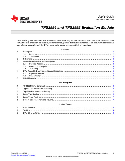
TPS2554 and TPS2555 Evaluation Module User's Guide
User's GuideSLVU462–June2011TPS2554and TPS2555Evaluation Module This user’s guide describes the evaluation module(EVM)for the TPS2554and TPS2555.TPS2554and TPS2555are precision-adjustable,current-limited,power-distribution switches.The document contains an operational description of the EVM,schematic,board layout,and bill of materials.Contents1Description (2)1.1Features (2)1.2Applications (2)2Schematic (3)3General Configuration and Description (4)3.1Physical Access (4)3.2Current-Limit Setpoint (4)3.3Test Setup (4)4EVM Assembly Drawings and Layout Guidelines (5)4.1Layout Guidelines (5)4.2PCB Drawings (5)5Bill of Materials (8)List of Figures1TPS2554/5EVM Schematic (3)2Typical TPS2554/5EVM Test Setup (5)3Top-Side Placement and Routing (6)4Layer-Two Routing (6)5Layer-Three Routing (7)6Bottom-Side Placement and Routing (7)List of Tables1User Interface (4)2Test Points (4)3EVM Bill of Materials (8)1 SLVU462–June2011TPS2554and TPS2555Evaluation Module Submit Documentation FeedbackCopyright©2011,Texas Instruments IncorporatedDescription 1DescriptionThe TPS2554EVM-010evaluation module allows reference circuit evaluation of the Texas Instruments TPS2554and TPS2555power-distribution switches.1.1Features•Precision adjustable,current-limited,power-distribution switch•Fast overcurrent response–1µs typical•80-mΩ,high-side MOSFET•Operating range:4.5V to5.5V1.2Applications•USB ports/hubs•Notebook personal computers(PC)2TPS2554and TPS2555Evaluation Module SLVU462–June2011Submit Documentation FeedbackCopyright©2011,Texas Instruments IncorporatedGeneral Configuration and Description 3General Configuration and Description3.1Physical AccessTable1lists the TPS2554/5EVM connector functionality,and Table2describes the test point availability.er InterfaceConnector Label DescriptionJ1VIN Input connectorJ2VOUT Output connectorJ3J3Input voltage jumper.Shunt can be removed to measure input current.J4J4Output voltage jumper.Shunt can be removed to measure output current.J5EN Enable jumper.Leave open to enable TPS2554and install shunt to enable TPS2555.J6ILIM_SEL Current limit select.Install shunt to select ILIM0(2.4A nominal),and remove shunt toselect ILIM1(1.2A nominal).D1(RED)FLT Fault LEDTable2.Test PointsTest Point Color Label DescriptionTP3RED IN Power switch input(IC side of J3shunt)TP4BLK GND Power switch input groundTP1WHT FLT Fault pin outputTP2RED VOUT Power switch outputTP5BLK GND Power switch output groundTP6WHT EN Enable pin input3.2Current-Limit SetpointR4and R5configure the current-limit setpoint for ILIM0and ILIM1,respectively(see J6in Table1).ILIM0or ILIM1setpoint can be adjusted using the following example by substituting R4or R5for RILIMx .In thisexample IOS=2A.The following example is an approximation only and does not take into account the resistor tolerance or the variation of ILIM.For exact variation of ILIM,see the TPS2554/TPS2555data sheet,SLVSAM0.IOS=48000/RILIMx=2ARILIMx=48000/IOS=48000/2=24000ΩChoose RILIMx=23.7kΩIOS=48000/23700=2.03A3.3Test SetupFigure2shows a typical test setup for TPS2554/5EVM.4TPS2554and TPS2555Evaluation Module SLVU462–June2011Submit Documentation FeedbackCopyright©2011,Texas Instruments IncorporatedV INOscilloscope EVM Assembly Drawings and Layout GuidelinesFigure2.Typical TPS2554/5EVM Test Setup4EVM Assembly Drawings and Layout Guidelines4.1Layout Guidelines•TPS2554/55placement:Place the TPS2554/55near the USB output connector and the150-µF OUT pin filter capacitor.Connect the exposed pad to the GND pin and the system ground plane using a viaarray.•IN pin bypass capacitance:Place the100-nF bypass capacitor near the IN and GND pins,and make the connection using a low-inductance trace.•ILIM0and ILIM1pin connections:Current-limit accuracy can be compromised by stray current leakage from a higher voltage source to the ILIM0or ILIM1pins.Ensure that adequate spacing existsbetween IN pin copper/trace and ILIM0pin trace to prevent contaminate buildup during the PCBassembly process.If a low-current-limit setpoint is required(RILIMx >200kΩ),use ILIM1for this case,as it is further away from the IN pin.4.2PCB DrawingsThe Figure3through Figure6show component placement and layout of the EVM.5 SLVU462–June2011TPS2554and TPS2555Evaluation Module Submit Documentation FeedbackCopyright©2011,Texas Instruments IncorporatedEVM Assembly Drawings and Layout Guidelines Figure 3.Top-Side Placement and RoutingFigure yer-Two Routing6TPS2554and TPS2555Evaluation ModuleSLVU462–June 2011Submit Documentation FeedbackCopyright ©2011,Texas Instruments Incorporated EVM Assembly Drawings and Layout Guidelinesyer-Three RoutingFigure6.Bottom-Side Placement and Routing7 SLVU462–June2011TPS2554and TPS2555Evaluation Module Submit Documentation FeedbackCopyright©2011,Texas Instruments IncorporatedEvaluation Board/Kit Important NoticeTexas Instruments(TI)provides the enclosed product(s)under the following conditions:This evaluation board/kit is intended for use for ENGINEERING DEVELOPMENT,DEMONSTRATION,OR EVALUATION PURPOSES ONLY and is not considered by TI to be a finished end-product fit for general consumer use.Persons handling the product(s)must have electronics training and observe good engineering practice standards.As such,the goods being provided are not intended to be complete in terms of required design-,marketing-,and/or manufacturing-related protective considerations, including product safety and environmental measures typically found in end products that incorporate such semiconductor components or circuit boards.This evaluation board/kit does not fall within the scope of the European Union directives regarding electromagnetic compatibility,restricted substances(RoHS),recycling(WEEE),FCC,CE or UL,and therefore may not meet the technical requirements of these directives or other related directives.Should this evaluation board/kit not meet the specifications indicated in the User’s Guide,the board/kit may be returned within30 days from the date of delivery for a full refund.THE FOREGOING WARRANTY IS THE EXCLUSIVE WARRANTY MADE BY SELLER TO BUYER AND IS IN LIEU OF ALL OTHER WARRANTIES,EXPRESSED,IMPLIED,OR STATUTORY,INCLUDING ANY WARRANTY OF MERCHANTABILITY OR FITNESS FOR ANY PARTICULAR PURPOSE.The user assumes all responsibility and liability for proper and safe handling of the goods.Further,the user indemnifies TI from all claims arising from the handling or use of the goods.Due to the open construction of the product,it is the user’s responsibility to take any and all appropriate precautions with regard to electrostatic discharge.EXCEPT TO THE EXTENT OF THE INDEMNITY SET FORTH ABOVE,NEITHER PARTY SHALL BE LIABLE TO THE OTHER FOR ANY INDIRECT,SPECIAL,INCIDENTAL,OR CONSEQUENTIAL DAMAGES.TI currently deals with a variety of customers for products,and therefore our arrangement with the user is not exclusive.TI assumes no liability for applications assistance,customer product design,software performance,or infringement of patents or services described herein.Please read the User’s Guide and,specifically,the Warnings and Restrictions notice in the User’s Guide prior to handling the product.This notice contains important safety information about temperatures and voltages.For additional information on TI’s environmental and/or safety programs,please contact the TI application engineer or visit /esh.No license is granted under any patent right or other intellectual property right of TI covering or relating to any machine,process,or combination in which such TI products or services might be or are used.FCC WarningThis evaluation board/kit is intended for use for ENGINEERING DEVELOPMENT,DEMONSTRATION,OR EVALUATION PURPOSES ONLY and is not considered by TI to be a finished end-product fit for general consumer use.It generates,uses,and can radiate radio frequency energy and has not been tested for compliance with the limits of computing devices pursuant to part15 of FCC rules,which are designed to provide reasonable protection against radio frequency interference.Operation of this equipment in other environments may cause interference with radio communications,in which case the user at his own expense will be required to take whatever measures may be required to correct this interference.EVM Warnings and RestrictionsIt is important to operate this EVM within the input voltage range of0V to5.5V and the output voltage range of0V to5.5V. Exceeding the specified input range may cause unexpected operation and/or irreversible damage to the EVM.If there are questions concerning the input range,please contact a TI field representative prior to connecting the input power.Applying loads outside of the specified output range may result in unintended operation and/or possible permanent damage to the EVM.Please consult the EVM User's Guide prior to connecting any load to the EVM output.If there is uncertainty as to the load specification,please contact a TI field representative.During normal operation,some circuit components may have case temperatures greater than85°C.The EVM is designed to operate properly with certain components above85°C as long as the input and output ranges are maintained.These components include but are not limited to linear regulators,switching transistors,pass transistors,and current sense resistors.These types of devices can be identified using the EVM schematic located in the EVM User's Guide.When placing measurement probes near these devices during operation,please be aware that these devices may be very warm to the touch.Mailing Address:Texas Instruments,Post Office Box655303,Dallas,Texas75265Copyright©2011,Texas Instruments IncorporatedIMPORTANT NOTICETexas Instruments Incorporated and its subsidiaries(TI)reserve the right to make corrections,modifications,enhancements,improvements, and other changes to its products and services at any time and to discontinue any product or service without notice.Customers should obtain the latest relevant information before placing orders and should verify that such information is current and complete.All products are sold subject to TI’s terms and conditions of sale supplied at the time of order acknowledgment.TI warrants performance of its hardware products to the specifications applicable at the time of sale in accordance with TI’s standard warranty.Testing and other quality control techniques are used to the extent TI deems necessary to support this warranty.Except where mandated by government requirements,testing of all parameters of each product is not necessarily performed.TI assumes no liability for applications assistance or customer product design.Customers are responsible for their products and applications using TI components.To minimize the risks associated with customer products and applications,customers should provide adequate design and operating safeguards.TI does not warrant or represent that any license,either express or implied,is granted under any TI patent right,copyright,mask work right, or other TI intellectual property right relating to any combination,machine,or process in which TI products or services are rmation published by TI regarding third-party products or services does not constitute a license from TI to use such products or services or a warranty or endorsement e of such information may require a license from a third party under the patents or other intellectual property of the third party,or a license from TI under the patents or other intellectual property of TI.Reproduction of TI information in TI data books or data sheets is permissible only if reproduction is without alteration and is accompanied by all associated warranties,conditions,limitations,and notices.Reproduction of this information with alteration is an unfair and deceptive business practice.TI is not responsible or liable for such altered rmation of third parties may be subject to additional restrictions.Resale of TI products or services with statements different from or beyond the parameters stated by TI for that product or service voids all express and any implied warranties for the associated TI product or service and is an unfair and deceptive business practice.TI is not responsible or liable for any such statements.TI products are not authorized for use in safety-critical applications(such as life support)where a failure of the TI product would reasonably be expected to cause severe personal injury or death,unless officers of the parties have executed an agreement specifically governing such use.Buyers represent that they have all necessary expertise in the safety and regulatory ramifications of their applications,and acknowledge and agree that they are solely responsible for all legal,regulatory and safety-related requirements concerning their products and any use of TI products in such safety-critical applications,notwithstanding any applications-related information or support that may be provided by TI.Further,Buyers must fully indemnify TI and its representatives against any damages arising out of the use of TI products in such safety-critical applications.TI products are neither designed nor intended for use in military/aerospace applications or environments unless the TI products are specifically designated by TI as military-grade or"enhanced plastic."Only products designated by TI as military-grade meet military specifications.Buyers acknowledge and agree that any such use of TI products which TI has not designated as military-grade is solely at the Buyer's risk,and that they are solely responsible for compliance with all legal and regulatory requirements in connection with such use. TI products are neither designed nor intended for use in automotive applications or environments unless the specific TI products are designated by TI as compliant with ISO/TS16949requirements.Buyers acknowledge and agree that,if they use any non-designated products in automotive applications,TI will not be responsible for any failure to meet such requirements.Following are URLs where you can obtain information on other Texas Instruments products and application solutions:Products ApplicationsAudio /audio Communications and Telecom /communicationsAmplifiers Computers and Peripherals /computersData Converters Consumer Electronics /consumer-appsDLP®Products Energy and Lighting /energyDSP Industrial /industrialClocks and Timers /clocks Medical /medicalInterface Security /securityLogic Space,Avionics and Defense /space-avionics-defense Power Mgmt Transportation and /automotiveAutomotiveMicrocontrollers Video and Imaging /videoRFID Wireless /wireless-appsRF/IF and ZigBee®Solutions /lprfTI E2E Community Home Page Mailing Address:Texas Instruments,Post Office Box655303,Dallas,Texas75265Copyright©2011,Texas Instruments Incorporated。
instruction-tuned models

指令调优模型(Instruction-tuned models)是一种机器学习模型,它通过调整模型的参数来提高其性能。
这种调整是基于特定任务或应用场景的需求和要求,例如对于一个需要识别图像中特定物体的任务,可以通过调整模型参数来提高其对特定物体的识别准确率。
指令调优模型通常采用深度学习技术,通过对大量数据进行训练和学习,从而实现对特定任务的优化。
在训练过程中,模型会根据输入数据和目标输出之间的差异来调整其参数,以最小化预测误差。
指令调优模型的优势在于其可以根据特定任务的需求进行定制化优化,从而提高模型的性能和准确性。
此外,由于模型参数的调整是基于数据的,因此它可以更好地适应不同的数据分布和场景,具有更好的泛化能力。
然而,指令调优模型也存在一些挑战和限制。
例如,对于一些复杂的任务或场景,可能需要更高级的优化算法和技术来实现更好的性能。
此外,由于模型参数的调整是基于数据的,因此对于一些数据量较小或数据质量较差的任务,可能无法获得理想的优化效果。
总之,指令调优模型是一种基于深度学习的机器学习技术,它可以根据特定任务的需求进行定制化优化,从而提高模型的性能和准确性。
然而,在实际应用中需要考虑其挑战和限制,并选择合适的优化算法和技术来实现更好的性能。
NXP silicon tuner Training

NXP Deployment Workshop January 2008 25
TDA18273 应用电路详解
只需4个电感 用于RF选择
无需LNA
NXP Deployment Workshop January 2008 26
电路图的关键点(1)
• 晶体部分
电容值 (18pF) 可能会根据使用的晶 体的参数不同而做修改。 18pF的容值是基于如下晶体的规格
NXP Deployment Workshop January 20模拟电视制式 (PAL, SECAM, NTSC) 和 数字电视 制式(DVB-T, DVB-T2, DVB-C/C2, ATSC, ISDB-T, DTMB)
NXP Deployment Workshop January 2008 17
fr4twolay板厚16mm43?线宽约13mm50mil?以尽量多的过孔包围rf线周围的地晶体周围的地也要用过孔包围?ifn和ifp走线尽量一致等长?用地将ifagc走线与if走线隔开并在地上打上过孔?电源走线i2c走线agc走线xtral走线等不要与rfif走线相交29nxpdeploymentworkshopjanuary2008pcb布版建议230电源退耦电容要尽量靠近芯片接地的引脚在向芯片外部地连接时也要同时向芯片底部的地连接这样可以加强接地并改善芯片散热电源退耦电容要尽量靠近芯片晶体走线及iic走线周围用地隔开并打上通孔芯片底部铺地且可焊接芯片底部铺地上打通孔在接地脚附近打孔加强与地层的接地nxpdeploymentworkshopjanuary2008pcb布版建议3跟踪滤波器部分31pcbsmdcoilsmdcapacitorhvqfn40packagebondingsactivedie请完全按照应用指导来布版nxpdeploymentworkshopjanuary200832pcb布版建议4建议芯片外部安装屏蔽壳建议金属屏蔽壳离芯片顶部高度大于3mm否则可能会影响到电感组件的品质因数nxpdeploymentworkshopjanuary2008tda18273评估板om3912om3910om3911单单tuner评估板可用于模拟和数字含解调部分的评估板针对于欧洲的应用模拟dvbtdvbc含解调部分的评估板针对于美洲市场模拟atscqam33nxpdeploymentworkshopjanuary2008工具及软件34?提供评估板用测试软件?提供驱动软件?提供软件集成指导书nxpdeploymentworkshopjanuary2008tda18273通过的各项测试报告35美国的数字电视国家标准欧盟电子标准欧盟数字电视标准丹麦芬兰冰岛挪威瑞典等北欧国家英国数字电视标准nxpdeploymentworkshopjanuary200836tda18273各项测试结果解析nxpdeploymentworkshopjanuary2008抗16mhz寄生谐波能力37测试条件
软件集成测试流程
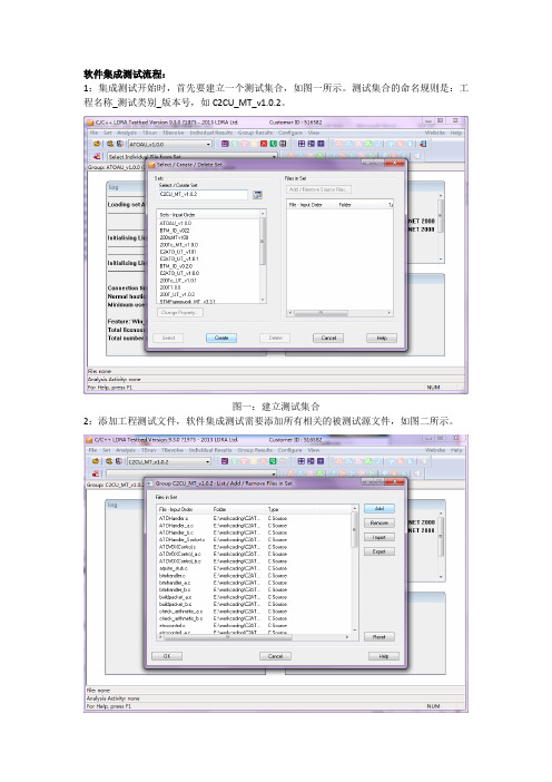
软件集成测试流程:
1:集成测试开始时,首先要建立一个测试集合,如图一所示。
测试集合的命名规则是:工程名称_测试类别_版本号,如C2CU_MT_v1.0.2。
图一:建立测试集合
2:添加工程测试文件,软件集成测试需要添加所有相关的被测试源文件,如图二所示。
图二:添加测试源文件3:添加测试头文件目录,如图三所示。
图三:添加头文件目录4:进行静态分析,如图四所示:
图四:进行静态分析
5:选择进入TBrun集成测试。
根据测试类别选择集成测试的测试项Integration Uint/Module Test,启动tbrun进入动态测试界面。
如图五所示。
图五:进入集成测试
6:建立测试序列。
为函数建立测试序列,命名规则为seq_MT_函数名。
图六:建立测试序列
7:配置测试环境。
建立完测试序列后要配置集成测试环境,操作步骤为:点击Configure->Instrumentation Options->Module Testing(第三项)->确定。
如图七所示。
图七:配置测试环境
8:添加被测试函数,如图八所示。
图八:添加被测试函数9:添加被调用函数,如图九所示。
图九:添加被调用函数10:创建测试案例,如图十所示。
图十:创建测试案例
11:执行测试案例,如图十一所示。
图十一:执行测试案例
12:导出测试报告,保存测试用例的regression报告和Dynamic Coverage Analysis报告。
如图十二所示。
图十二:导出测试报告。
Momentus 安装指南说明书

Momentus Installation GuideST94011A, ST94811A, ST92011A, and ST92811AATA Interface Disc DrivesPublication Number: 100271723, Rev. B, April 2004The easiest way to install your driveMany of today’s mobile computers have been designed to make it possible for the end user to replace the hard drive. Refer to your system’s user man-ual for the location of the hard drive compartment and the specific instruc-tions regarding replacement.Some mobile systems are sealed and require specialized tools to gain access to the hard drive.Caution.Special training or tools may be needed to service some mobile computers. In some cases, opening the case may void your war-ranty. Consult your system documentation.Seagate recommends taking your system to an authorized service techni-cian to replace your hard drive.Refer to your system manufacturer’s support website for the most up-to-date information. Read and follow all instructions regarding the proper steps to be taken when replacing the systems hard drive.What you need• A Phillips screwdriver•Existing drive mounting screws (reuse)•Existing drive mounting framework, cage or tray (reuse)•A TA interface adapter (built into notebook and laptop systems) Handling precautions/electrostatic discharge protection •Disc drives are fragile. Do not drop or jar the drive. Handle the drive only by the edges or frame. Keep the drive in the electrostatic discharge (ESD) bag until you are ready to install it to minimize handling damage.•Drive electronics are extremely sensitive to static electricity. While installing the drive, wear a wrist strap and cable connected to ground.•T urn off the power to the host system during installation.•Do not disassemble the drive. Doing so voids the warranty. See the war-ranty information on page 2.•Do not apply pressure or attach labels to the circuit board or to the top of the drive.Drive characteristicsST94011A ST92011A Formatted capacity 40 Gbytes20 GbytesT otal number of sectors* 78,140,16039,070,080Cache size 2 Mbytes 2 MbytesST94811A ST92811A Formatted capacity 40 Gbytes20 GbytesT otal number of sectors* 78,140,16039,070,080Cache size8 Mbytes8 Mbytes*One sector equals 512 bytes.Replacing the existing hard driveEach system has its own unique hard drive compartment. Refer to your system manual to locate the hard drive compartment and for instructions on removing and replacing the hard drive.Warning.T urn off the computer. If you have a notebook or laptop com-puter, disconnect the power charger/adapter and remove thebattery before you open the case or touch any internal compo-nents.Note.This drive is designed for a host computer that supplies interface signals and +5V power through a single 44-pin connector. Most mobile computers have a fixed connector that attaches directly to the drive.Setting the jumpersRefer to the jumper settings in Figure 1 or on your drive label to configure the drive for your system. Jumper settings can also be accessed online from our web site at .Master or single drive: Use the options jumper block shown in Figure 1 to configure the drive for operation. This jumper block is the 4-pin header adjacent to pins 1 and 2 of the I/O signal pins.Note.For mobile system operation, use cable select (default) or master. Figure 1.Yfour screws in the bottom-mounting holes. See Figure 2 for drive mounting dimensions. Follow these important mounting precautions when mounting the drive:•Allow a minimum clearance of 0.030 inches (0.76 mm) around the entire perimeter of the drive for cooling.•Use only M3 UNC mounting screws. (Reusing the existing screws may be acceptable provided the maximum screw penetration depth of 0.098 inches is not exceeded.)•Gently tighten the mounting screws (maximum torque: 4.0 in-lb).•Four (4) threads (0.080 inches) minimum screw engagement recom-mended.Figure 2.Mounting dimensions—end, top, side, and bottom views Configuring the BIOSAfter completing the drive installation, restart your computer. Y our com-puter may automatically detect your new drive. If your computer does not automatically detect your new drive, follow the steps below.1.Restart your computer. While the computer restarts, run the systemsetup program (sometimes called BIOS or CMOS setup). This is usu-ally done by pressing a special key, such as DELETE, ESC, or F1 dur-ing the startup process.2.Within the system setup program, instruct the system to auto detectyour new drive.3.Save the settings and exit the setup program.When your computer restarts, it should recognize your new drive. If your system still doesn’t recognize your new drive, see the troubleshootingsection on this sheet.System manufacturer’s operating system restore CDRefer to your mobile system documentation for specific instructions on restoring the operating system on your newly installed hard drive. Many computers require the use of an operating system restore CD, originally shipped with the system, to reload the operating system on the hard drive. Microsoft operating system installation instructionsFor detailed information about installing a Microsoft operating system on your new Seagate drive, refer to the Microsoft Knowledgebase article refer-ences below. To locate an article, go to and enter the article number in any search box on the Microsoft web site. For example, to view the Knowledgebase article for installing Windows XP on your new Seagate drive:1.Open your browser.2.Go to .3.Enter 313348 in the Microsoft web site search box.4.Press Enter.The article is displayed on your screen.Operating system Microsoft Knowledgebase article numbers Windows XP313348Windows 2000/NT308209 (see also: 175761)Windows Me/98/95255867 (see also: 166172)Preparing the drive using DiscWizardWe recommend using DiscWizard Starter Edition to automatically partition and format your drive. DiscWizard software is available at and is free. T o run DiscWizard:1.Insert your bootable DiscWizard Starter Edition diskette or CD and fol-low the instructions. DiscWizard will guide you through the installation process.2.Boot your computer from the Windows operating system CD-ROM orfrom your system startup diskette with the Windows CD loaded. Follow the instructions provided on your screen.TroubleshootingIf your drive is not working properly, these troubleshooting tips may help solve the problem.1.Does the drive spin up? A spinning drive produces a faint whine andclicking noise. If your drive does not spin, check that the power con-nector and interface cable are securely attached.2.Does the computer recognize the drive? Verify that the drive isenabled in the system CMOS or setup program. If not, select the auto detect option and enable it. If your drive has a problem, it may not be recognized by the system. If the operating system does not recognize the drive, you need to load your host adapter drivers.3.Does FDISK detect the drive? Run the FDISK program located onyour Windows startup diskette. Type fdisk/status to verify that your hard drive is present and recognized by the system.4.I’m running Windows 98 and FDISK is not reporting the fullcapacity of my drive. Why? Y ou need to upgrade your version of FDISK if you are using the diskettes or CD that came with your original Windows 95 or 98 operating system. Microsoft provides a free down-loadable FDISK upgrade. See Microsoft Knowledgebase article num-ber: 263044 located at .5.Does ScanDisk find the drive defect-free? ScanDisk is a utilitylocated on your Windows startup diskette that scans the drive for defects. If defects are detected, this may be an indication of a problem.6.Why does my computer hang on startup? Verify that your system isA TA compatible. Y ou need either an A TA-compatible motherboard con-nector or AT A host adapter to use this drive.Note.If these tips do not answer your question or solve the problem, con-tact your dealer or visit to download SeaTools™ disc diagnostics software and more troubleshooting advice.Seagate support servicesFor online information about Seagate products, visit or e-mail your **************************************.If you need help installing your drive, consult your dealer first. If you need additional help, call a Seagate technical support specialist. Before calling, note your system configuration and drive model number.Africa+1-405-324-4714Netherlands00 800-47324283 Australia1800-14-7201New Zealand0800-443988Austria0 800-20 12 90Norway00 800-47324283 Belgium00 800-47324283Poland00 800-311 12 38 China*800-810-9668Spain00 800-47324283 Denmark00 800-47324283Sweden00 800-47324283 France00 800-47324283Switzerland00 800-47324283 Germany00 800-47324283Singapore800-1101-150Hong Kong800-90-0474Taiwan*00-800-0830-1730 Hong Kong†001-800-0830-1730Thailand001-800-11-0032165 India1-600-33-1104Turkey00 800-31 92 91 40 Indonesia001-803-1-003-2165United Kingdom00 800-47324283 Ireland00 800-47324283USA/Canada/1-800 SEAGATE or Italy00 800-47324283Latin America+1-405-324-4700 Japan0034 800 400 554Other EuropeanMalaysia1-800-80-2335countries+1-405-324-4714 Middle East+1-405-324-4714*Mandarin†CantoneseWarranty.T o determine the warranty status of your Seagate disc drive, contact your place of purchase or visit our web site at for more information. Return Merchandise Authorization (RMA). Run SeaT ools to diagnose your drive before requesting a return authorization. In addition, please verify that your drive is defective by following the troubleshooting checklist in this guide. Seagate offers com-prehensive customer support for all Seagate drives worldwide. Seagate customer service centers are the only facilities authorized to service Seagate drives. Drive return procedures vary depending on geographical location and are subject to current international trade regulations.Shipping the driveCaution.Back up the data before shipping. Seagate assumes no responsibility for data lost during shipping or service.Shipping drive in an unapproved container voids the warranty. Pack the drive with original box and packing materials. Use no other materials. This prevents electrical and physical damage in transit.Electromagnetic compliance for the European Union. This model complies with the European Union requirements of the Electromagnetic Compatibility Directive 89/ 336/EEC of 03 May 1989 as amended by Directive 92/31/EEC of 28 April 1992 and Directive 93/68/EEC of 22 July 1993. Compliance of this drive, as a system compo-nent, was confirmed with a test system. We cannot guarantee that your system will comply. The drive is not meant for external use (without properly designed enclosure, shielded I/O cable, etc.).Sicherheitsanleitung 1. Das Gerrät ist ein Einbaugerät, das für eine maximale Umgebungstempeatur von 60°C vorgesehen ist. 2. Zur Befestigung des Lufwerks werden 4 Schrauben 6-32 UNC-2A benötigt. Bei seitlicher Befestigung darf die maxi-male Länge der Schrauben im Chassis nicht merh als 3,3 mm und bei Befestigung an der Unterseite nicht mehr als 5,08 mm betragen. 3. Als Versorgungsspannugen wer-den benötigt: +5V +/- 5% 0,74A; +12V +/- 5% 2,8A 4. Die Versorgungsspannung muss SELV entsprechen. 5. Alle Arbeiten auf dem Festplattte dürfen nur von Ausgebi-letem Serciepersonal durchgeführt werden. Bitte entfernen Sie nicht die Aufschriften-schilder des Laufwerkes. 6. Der Einbau des Laufwerkes muss den Anforderungen gemäss DIN IEC 950 VDE 0805/05.90 entspreche.© 2003, 2004 Seagate Technology LLC. All rights reservedPublication number: 100271723, Rev. B, April 2004, Printed in U.S.A.Seagate, Seagate Technology, and the Seagate logo are registered trademarks or trademarks of Seagate Technology LLC. DiscWizard, Momentus, and SeaTools are trademarks of Seagate Technology LLC. Other product names are registered trade-marks or trademarks of their owners. Seagate reserves the right to change, without notice, product offerings or specifications.。
Nsight Eclipse Plugins Edition DG-06450-001 _v9.1

Getting Started GuideTABLE OF CONTENTS Chapter 1. Introduction (1)1.1. About Nsight Eclipse Plugins Edition (1)Chapter 2. Using Nsight Eclipse Edition (2)2.1. Installing Nsight Eclipse Edition (2)2.1.1. Installing CUDA T oolkit (2)2.1.2. Configure CUDA T oolkit Path (2)2.2. Nsight Eclipse Main Window (4)2.3. Creating a New Project (5)2.4. Importing CUDA Samples (6)2.4.1. cuHook Sample (6)2.5. Configure Build Settings (7)2.6. Debugging CUDA Applications (8)2.7. Remote development of CUDA Applications (10)2.8. Debugging Remote CUDA Applications (12)2.9. Profiling CUDA applications (18)2.10. Importing Nsight Eclipse Projects (19)2.11. More Information (21)LIST OF FIGURESFigure 1 Nsight main window after creating a new project (5)Figure 2 Debugging CUDA application (9)Figure 3 Debugging CUDA application (10)Figure 4 Debugging remote CUDA application (18)Figure 5 Profiling CUDA Application (19)This guide introduces Nsight Eclipse Plugins Edition and provides instructions necessary to start using this tool. Nsight Eclipse is based on Eclipse CDT project. Fora detailed description of Eclipse CDT features consult the integrated help "C/C++ Development User Guide" available from inside Nsight (through Help->Help Contents menu).1.1. About Nsight Eclipse Plugins EditionNVIDIA® Nsight™ Eclipse Edition is a unified CPU plus GPU integrated development environment (IDE) for developing CUDA® applications on Linux and Mac OS X for the x86, POWER and ARM platforms. It is designed to help developers on all stages of the software development process. Nsight Eclipse Plugins can be installed on vanilla Eclipse 4.4 or later using the standard Help->Install New Software.. Menu. The principal features are as follows:‣Edit, build, debug and profile CUDA-C applications‣CUDA aware source code editor – syntax highlighting, code completion and inline help‣Graphical user interface for debugging heterogeneous applications‣Profiler integration – Launch visual profiler as an external application with the CUDA application built in this IDE to easily identify performance bottlenecksFor more information about Eclipse Platform, visit 2.1. Installing Nsight Eclipse EditionNsight Eclipse Plugins archive is part of the CUDA Toolkit. Nsight Eclipse Plugins archive can be installed using the Help -> Install New Software... Menu on Eclipse 4.4 or later2.1.1. Installing CUDA T oolkitTo install CUDA Toolkit:1.Visit the NVIDIA CUDA Zone download page:/object/cuda_get.html2.Select appropriate operating system. Nsight Eclipse Edition is available in Mac OS X and Linux toolkit packages.3.Download and install the CUDA Driver.4.Download and install the CUDA Toolkit.5.Follow instructions to configure CUDA Driver and Toolkit on your system.2.1.2. Configure CUDA T oolkit PathTo get started, CUDA Toolkit path must be configured in Eclipse with Nsight Plugins:1.Open the Preferences page, Window > Preferences.2.Go to CUDA toolkit section.3.Select the CUDA toolkit path to be used by Nsight. CUDA tookits that are installed in the default location will automatically appear.4.CUDA toolkit path can be also specified in the project properties page in order to use different toolkit for a project.5.For QNX: When QNX is selected as Target OS, a dialog will be displayed to set theQNX_HOST and QNX_TARGET environment variables if they were not already set.QNX_HOST environment variable identifies the directory that holds the host-related components:QNX_TARGET environment variable identifies the directory that holds the target-related components:2.2. Nsight Eclipse Main WindowOn the first run Eclipse will ask to pick a workspace location. The workspace is a folder where Nsight will store its settings, local files history and caches. An empty folder should be selected to avoid overwriting existing files.The main Nsight window will open after the workspace location is selected. The main window is divided into the following areas:‣Editor - displays source files that are opened for editing.‣Project Explorer - displays project files‣Outline - displays structure of the source file in the current editor.‣Problems - displays errors and warnings detected by static code analysis in IDE or bya compiler during the build.‣Console - displays make output during the build or output from the running application.2.3. Creating a New Project1.From the main menu, open the new project wizard - File > New... > C/C++ Project2.Specify the project name and project files location.3.Specify the project type like executable project.4.Specify the CUDA toolchain from the list of toolchains.5.Specify the project configurations on the next wizard page.plete the wizard.The project will be shown in the Project Explorer view and source editor will be opened.7.Build the project by clicking on the hammer button on the main toolbar.Figure 1 Nsight main window after creating a new project2.4. Importing CUDA SamplesThe CUDA samples are an optional component of the CUDA Toolkit installation. Nsight provides a mechanism to import these samples and work with them easily: Samples that use the CUDA driver API (suffixed with "Drv") are not supported byNsight.1.From the main menu, open the new project wizard - File > New... > C/C++ Project2.Specify the project name and project files location.3.Select Import CUDA Sample under Executable in the Project type tree.4.Select CUDA toolchain from the Toolchains option. location.5.On the next wizard page select project sample you want to import. Also select the target CPU architecture. Press Next...6.Specify the project parameters on the next wizard page.plete the wizard.The project will be shown in the Project Explorer view and source editor will be opened.8.Build the project by clicking on the hammer button on the main toolbar.2.4.1. cuHook SamplecuHook sample builds both the library and the executable. cuHook sample should be imported as the "makefile" project using the following steps.1.From the main menu, open the new project wizard - File > New... > C/C++ Project2.Select project type "Makefile project" and choose "Empty Project"3.Specify the project name and project files location.plete the wizard.The project will be shown in the Project Explorer view.5.Right click on the project - Import... > General > File System6.On the next wizard page, select the location of cuHooksample(Samples/7_CUDALibraries/cuHook)7.Select all the source files and makefile and Finish the wizard8.Build the project by clicking on the hammer button on the main toolbar.9.To run the sample, from the main menu - Run > Run Configurations... > Select the executable > Go to Environment tab > New... > enter Name=LD_PRELOAD, Value=./ libcuhook.so.1 > Run will execute the sample2.5. Configure Build SettingsTo define build settings: In the C/C++ Projects view, right-click your project, and select Properties. Select C/C++ Build, Settings from the list.The following are the categories of Nvcc linker settings that can be configured for the selected project.All options field in the main page is not editable and it's the collection of options setin the child categories.‣Libraries - Configure library search path(-L) and to include linker libraries(-l). When you are cross compiling for different target os, the library search path should point to the appropriate location where the target os libraries are present.‣Miscellaneous - Set additional linker options and option to link with OpenGL libraries.‣Shared Library Settings - Set option to build a shared library.The following are the categories of Nvcc Compiler settings that can be configured for the selected project.All options field in the main page is not editable and it's the collection of options set‣Dialect - Select the language standard and dialect options.‣Preprocessor - Add the defined and undefined symbols for the preprocessor.‣Includes - Set include paths and include files for the compiler.‣Optimization - Set the compiler optimization level.‣Debugging - Set the options to generate debug information.‣Warnings - Set inhibit all warning messages.‣CUDA - Generate code for different real architectures with the PTX for the same vitrual architectures.2.6. Debugging CUDA ApplicationsNsight must be running and at least one project must exist.1.In the Project Explorer view, select project you want to debug. Make sure the project executable is compiled and no error markers are shown on the project.2.Right click on the project and go to Debug As > NVIDIA CUDA GDB Debugger menu.3.You will be offered to switch perspective when you run debugger for the first time. Click "Yes".Perspective is a window layout preset specifically designed for a particular task.4.Application will suspend in the main function. At this point there is no GPU code running.5.Add a breakpoint in the device code. Resume the application.Debugger will break when application reaches the breakpoint. You can now explore your CUDA device state, step through your GPU code or resume the application.Figure 2 Debugging CUDA applicationAdditional debugger options can be set in the debug configuration dialog through Run > Debug Configurations .. menu..Figure 3 Debugging CUDA application2.7. Remote development of CUDA ApplicationsNsight Eclipse Edition also supports remote development of CUDA application starting with CUDA Toolkit 6.0. The picture below shows how Nsight Eclipse Edition can beused for local as well as remote development:For remote development you do not need any NVIDIA GPU on your host system. The remote target system can be a Linux x86 or POWER system with an NVIDIA GPU or an Tegra-based ARM system. Nsight IDE and UI tools can only be hosted on x86 and POWER systems.Nsight Eclipse Plugins supports the cross compilation mode for remote devices.In the cross compilation mode the project resides on the host system and the cross compilation is also done on the host system. The cross compilation mode is only supported on an Ubuntu x86 host system.To cross compile select the target cross compile architecture in CPU architecture dropdown in the project properties page:2.8. Debugging Remote CUDA Applications Remote debugging is available starting with CUDA Toolkit 5.5. A dedicated GPU is not required to use Nsight remote debugging UI. A dedicated GPU is still required on the debug target. Only Linux targets are supported. Debug host and target may run different operating systems or have different CPU architectures. The remote machine must be accessible via SSH and CUDA Toolkit must be installed on both machines.If there is a firewall between the host and the target, it must be set up to let RSP1.Select the project and right click then go to Debug As...>NVIDIA CUDA GDBDebugger(Remote) menu item.2.Type the full path to a local executable or select one using the Local file... button.3.Select a remote connection from a drop-down list or press the Add connection... button to create a new one.4.If you are creating a new remote connection, select the SSH Only connection type, press Next, and type the host name(or IP address) as well as the connection name anddescription (both are optional) and then press Finish.5.For Android devices: To configure the remote connection using Android debug bridge, select the Android debug bridge from the Remote Connection drop-downlist, Android device must be connected to the host system using USB port.Press Manage button, and enter or select the path to adb utility. You need to install Android SDK platform tools to use Android debug bridge. press Detect button tofind the android device available through ADB.6.Optional: Press Connect to verify the selected remote connection.7.Press the Next button.8.Type the full path to cuda-gdbserver on the remote system or select one using theBrowse... button.9.Click on "Add new path" or on the Browse... button to specify the path to the shared libraries the remote application depends on.10.C lick on the Finish button to finish the new debug configuration wizard and start debugging the application.11.Y ou will be offered to switch perspective when you run the debugger for the first time. Click Yes.Perspective is a window layout preset specifically designed for a particular task. The debugger will stop at the application main routine. You can now set breakpoints, orresume the application.Figure 4 Debugging remote CUDA application2.9. Profiling CUDA applicationsNsight must be running and at least one project must exist. Profiler cannot be used when debugging session is in progress.Nsight Eclipse Edition profiling features are based on the NVIDIA Visual Profiler ( nvvp ) code. Nsight Eclipse Plugins Edition will launch the Visual Profiler as an external tool with the executable and other information from the selected project.1.In the Project Explorer view, select project you want to profile. Make sure the project executable is compiled and no error markers are shown on the project.2.Select the project and right click and go to Profile As>NVIDIA Visual Profiler menu.Nsight Eclipse will launch the Visual Profiler to specify extra profiler options with the executable information already passed from the selected project.Figure 5 Profiling CUDA Application2.10. Importing Nsight Eclipse ProjectsThe projects that are created with Nsight Eclipse Edition can be imported into the Eclipse workbench with Nsight Eclipse plugins.1.Open Nsight Eclipse edition and select the project that needs to be exported.2.Right click on the Nsight Eclipse project and go to - Export > C/C++ > C/C++ Project Settings > Next menu.3.Select the project and settings to export.4.Specify the "Export to file" location.5.Settings will be stored in the given XML file.6.Go to Eclipse workbench where the project settings needs to be imported.7.Create a C/C++ Project from the main menu File > New > C/C++ Project8.Specify the project name and choose Empty project type with CUDA toolchains.9.Right click on the project to import the source files. Import > General > File System >(From directory) or copy the source files from the existing project.10.I mport the project settings like include paths and symbols using the following right click menu Import > C/C++ > C/C++ Project Settings >Next...11.S elect the location of the project settigns file and select the project and configurationon the next wizard page.12.C omplete the wizard.The project settings will be imported from the file exported from Nsight Eclipse Edition.13.B uild the project by clicking on the hammer button on the main toolbar.2.11. More InformationMore information about the Eclipse CDT features and other topics is available in the Help contents. To access Help contents select Help->Help Contents from the Nsight main menu.More information about CUDA, CUDA Toolkit and other tools is available on CUDAweb page at /cudaNoticeALL NVIDIA DESIGN SPECIFICATIONS, REFERENCE BOARDS, FILES, DRAWINGS, DIAGNOSTICS, LISTS, AND OTHER DOCUMENTS (TOGETHER AND SEPARATEL Y, "MATERIALS") ARE BEING PROVIDED "AS IS." NVIDIA MAKES NO WARRANTIES, EXPRESSED, IMPLIED, STATUTORY, OR OTHERWISE WITH RESPECT TO THE MATERIALS, AND EXPRESSL Y DISCLAIMS ALL IMPLIED WARRANTIES OF NONINFRINGEMENT, MERCHANTABILITY, AND FITNESS FOR A PARTICULAR PURPOSE.Information furnished is believed to be accurate and reliable. However, NVIDIA Corporation assumes no responsibility for the consequences of use of such information or for any infringement of patents or other rights of third parties that may result from its use. No license is granted by implication of otherwise under any patent rights of NVIDIA Corporation. Specifications mentioned in this publication are subject to change without notice. This publication supersedes and replaces all other information previously supplied. NVIDIA Corporation products are not authorized as critical components in life support devices or systems without express written approval of NVIDIA Corporation.TrademarksNVIDIA and the NVIDIA logo are trademarks or registered trademarks of NVIDIA Corporation in the U.S. and other countries. Other company and product names may be trademarks of the respective companies with which they are associated. Copyright© 2007-2018 NVIDIA Corporation. All rights reserved.。
人工智能训练师考核模块需求说明

人工智能训练师考核模块需求说明
15、开发语言:Python、C/C++;
16、超声波测距传感器:接口:≥2个,具有语音播报功能
“识别到前超声波”、“识别到后超声波”;
17 开关接口:不少于1路启动开关、不少于1路紧急停止
按钮;
18.人工智能车类型:阿克曼结构(前轮转向,后轮驱动);
19.人工智能车尺寸要求:长度≥400mm;宽度≥260mm,高
度≥190mm;
20.最小转弯直径:≤1100mm(人工智能车转一周,测量小车
两外侧之间的距离,如下图所示);
21.车轮数量:4个;
22.轴距≥140mm, 轮距≥230mm (轴距是指前轴中心到后轴中心的距离,轮距是左右两车轮两个中心平面之间的距离);
23.舵机数量:不少于1个;
24:开盖形式:为了方便学生对硬件设备进行装调实验,要求小车采用翻盖设计,方便操作,铰链开合,开合角度≥160度;
25.遥控形式:支持PS2无线手柄控制,通过遥杆对速度无级调节;
4、人工智能训练沙盘车道按照下图轨道线定制。
5、人工智能训练沙盘提供14类交通标志、可变交通灯等,道路表面交通标志、标线符合交通线路设计规范,如斑马线、转弯线等,用于验证和应用智能避障、路径规划等人工智能算法。
6、人工智能监测终端:
1)分辨率3840*2160;
2)终端显示尺寸:长度≥2200mm,宽度≥1250mm;
3)CPU:CortexA73 四核;
4)内存:4GB;
5)GPU:GMCI;
6)存储:64G;
7)WiFi6;
8)蓝牙5.2;
9)HDMI:3个;
10)USB:2个;
11)以太网:1个;。
6-sigma trainiing(六西格码培训资料)

-7 -6 -5 -4 -3 -2 -1 0 1 2 3 4 5 6 7
68.27 % 95.45 % 99.73 % 99.9937 % 99.999943 % 99.9999998 %
Axis graduated in Sigma
result: 317300 ppm outside (deviation)
6-Sigma Training
2
COURSE ABSTRACT
This course is to introduce the ways of Process Control System targeting to 6-sigma Quality in the manufacturing areas. The benchmark of Six Sigma will be shared during the course. In order to achieve it, series of measurement system capabilities, performance metrics and process control methodology will be discussed.
45500 ppm 2700 ppm
63 ppm 0.57 ppm 0.002 ppm
11
Six Sigma...And the Statistics
Lower spec. limit
-1.5 Sigma +1.5 Sigma
Upper spec. limit
3.4 ppm or Zero
-7.0 -6.0 -5.0 -4.0 -3.0 -2.0 -1.0 0.0 1.0 2.0 3.0 4.0 5.0 6.0 7.0
osrm-text-instructions 使用方法 -回复

osrm-text-instructions 使用方法-回复OSRM 是一个开源的路由引擎,用于计算最短路径和路线指导。
它是基于OpenStreetMap(OSM)数据构建的,可用于各种应用程序,包括导航系统、配送服务、地图分析等。
本文将逐步解释如何使用OSRM,包括数据准备、安装和配置,以及如何计算路由和获取路线指导。
第一步:准备数据在开始使用OSRM 之前,您需要准备地图数据。
OSRM 支持OpenStreetMap 的.pbf 格式数据。
您可以通过以下步骤获取地图数据:1. 访问OpenStreetMap 网站(2. 在地图上导航到您感兴趣的区域。
3. 点击左上角的“导出”按钮。
4. 在导出选项中,选择“OSM数据”作为导出格式,并选择您想要的区域范围。
5. 点击“导出”按钮,保存地图数据的.pbf 文件到本地计算机。
第二步:安装和配置OSRM在准备好地图数据后,您需要安装和配置OSRM。
以下是安装和配置OSRM 的步骤:1. 访问OSRM 的GitHub 页面(2. 根据您的操作系统,按照指示下载和安装OSRM。
3. 安装完成后,打开命令行界面。
4. 使用命令行进入到OSRM 的安装目录。
5. 运行以下命令以处理地图数据并生成OSRM 文件:osrm-extract、osrm-partition、osrm-customize 和osrm-prepare。
这些命令将生成包含路网数据的.osrm 文件。
第三步:计算路由和获取路线指导一旦您完成了数据准备和OSRM 的安装配置,您可以开始计算路由和获取路线指导。
以下是一些常见的操作:1. 单点路由:使用osrm-routed 命令来启动OSRM 的服务器,并提供起点和终点的经纬度坐标。
服务器将返回最短路径和路线指导信息。
2. 多点路由:如果您需要计算多个点之间的最短路径,可以使用osrm-tools 提供的命令行工具。
这些工具包括osrm-contract 和osrm-route。
- 1、下载文档前请自行甄别文档内容的完整性,平台不提供额外的编辑、内容补充、找答案等附加服务。
- 2、"仅部分预览"的文档,不可在线预览部分如存在完整性等问题,可反馈申请退款(可完整预览的文档不适用该条件!)。
- 3、如文档侵犯您的权益,请联系客服反馈,我们会尽快为您处理(人工客服工作时间:9:00-18:30)。
scheduler
• DAT uses the due date and due time • SEQ uses the sequence number • E.g. DAT, SEQ uses the due date + due time + sequence
Process Setup: Order Processor (OP)
yes
no no
HigherPointAction Site SalesOrder ZeroQuantity ValidateAgainst AutoAdd AutoObsolete UseCounter
SKIP NODSITE SONOD NO Sales Order Yes None Yes
6 Opvalidatio n Opvalidatio n opcreate 7 8
Create the Rule Group <add a record>
– – – – – Rule Group: Description: Rule Group Type: Execute Events Sequentially: Execute Rules Sequentially: S00_OP_RG Create with parts Order Processor <unchecked> <checked>
no no no no no
Parameter ID Minval Maxval IncrVal Skiplist addwrap TwinAction
Value 1000 3000 1
Opvalidatio n Opvalidatio n Opvalidatio n opvalidatio n
2 3 4 5
• • Assign the rule group Assign values to the process parameters
– – – – – – BroadcastPoint Log Debug Trace StopOnError OPErrorEmailList
Rule Group - hierarchy
OR-1 OR-2
OP-1 OP-2
PSK1
OS-1 (SAU 1)
PSK2 COVH COVD WO
OS-2 (SAU 2)
JIT/S: Concepts - Processes
REVIEW REVIEW REVIEW SLIDE SLIDE SLIDE
Processes: Rule-based processes consist of groups of rules that act on data. For example, the specific functions of the Order Processor and Order Scheduler are controlled by rules and their parameters. Although the Order Receiver is a process, it is not rule-based. Creation Rule Group Rule 1 Rule 2 Deletion Rule Group How Process Parameters and Rule Parameters control a process.
Each Rule has 0..many parameters
Also - each Rule Group has 0..many parameters Rule Group consists of 1..many rules
Process Setup: Order Processor (continued)
1. 2. 3. 4. Create rule group (e.g. S00_OP_RG) Link rules to a rule group Assign Parameters for the rules of that rule group Create the order processor process
• Validation rules based on broadcast point • Validation rules based on action type (i.e. add, change, delete)
– Creates product family orders – Creates the pre-schedule-key (PSK) for use by the order
OPValidateAttributes
OP Validate Atts
Order Receiver
Read Channel Write to db Read COVH & COVD
REVIEW REVIEW REVIEW SLIDE SLIDE SLIDE
Order Processor
Order Scheduler
Validate Info Write CO Write PFO Write WO Update PSK •Generate labels •Generate shopping Lists
JIT/S Setup Training (Module 6.9) continued
November 9th 2005 Version 0.05e Section 4
QAD Confidential - not for re-use
Here data..data..
Goals of this Chapter
Order Scheduler
The order scheduler creates firm work orders for each shippable assembly unit (SAU). One (1) order scheduler is for one (1) SAU
Order Receiver, Processor, Scheduler
Process Parameters Debug BRD PT PROCESS
e.g. Order Processor
Rule Parameters Seq Incr High value
JIT/S: Process Setup
Process Parameters
10054 - Training Material v01.vsd - (Processes) Aug 18, 2004 10:05
OPValidateTwins OPValDuplicate OPHigherPoint OPValidateParts
OP Check twins
Check if it is already processed Check higher point Part Validation
yes
no no
Ignore
What are we going to learn?
– Setting up JIT/S processes:
• Order Receiver (see chapter 3) • Order Processor • Order Scheduler
The JIT/S System
Order Processor Order Receiver
Order Processor
The order processor detects the COVs generated by the order receiver invokes different rules—depending on the type (e.g. new, deletion, amendment) and the broadcast point—to process them.
Analysis of how the Order Processor should be setup:
– Determine if the order processor should run continuously – Determine if the order processor should continue when it finds an error – Determine which broadcast point(s) will be handled by this order processor
Order Scheduler
Packaging, Shipping
Creating a Relationship – Customer line to JIT/S processes
Customer Production Line EW Channel1 Channel2 LW
Pre-Schedule-Key
Process Setup: Order Processor (continued)
Link the rules to the Rule Group
OP-NOD-CREATE-WITH-PARTS - Class 3 (creation)
Class Code Opvalidatio n 1 Sort Order Rule Name OPCheckSeq Description OP Check Sequence Num ber Continu e Process Disab. yes
Process
Process Order Receiver Parameters
– Parameters for the process e.g. Broadcast Point.
Create Rule Group
Link Rules
Rule Group Parameters
