831B中文资料
3843B资料
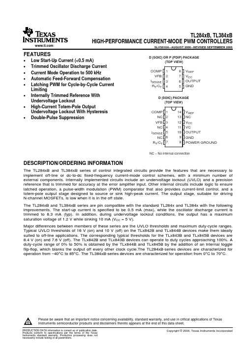
TL3843BD-8
SOIC – D (8 pin)
Reel of 2500 Tube of 75
TL3843BDTL3844BDR-8
Tube of 75
TL3845BD-8
Reel of 2500
TL3845BDR-8
Tube of 75
TL3842BD
Copyright © 2006, Texas Instruments Incorporated
元器件交易网
TL284xB, TL384xB HIGH-PERFORMANCE CURRENT-MODE PWM CONTROLLERS
SLVS610A – AUGUST 2006 – REVISED SEPTEMBER 2006
S
R
CurrentSense
Comparator
PWM Latch
Submit Documentation Feedback
3
元器件交易网
TL284xB, TL384xB HIGH-PERFORMANCE CURRENT-MODE PWM CONTROLLERS
Reel of 2500
TL3842BDR
Tube of 75
TL3843BD
SOIC – D (14 pin)
Reel of 2500 Tube of 75
TL3843BDR TL3844BD
Reel of 2500
TL3844BDR
Tube of 75
TL3845BD
Reel of 2500
TL3845BDR
RT/CT 7
14 VREF 13 NC 12 VCC 11 VC 10 OUTPUT 9 GND 8 POWER GROUND
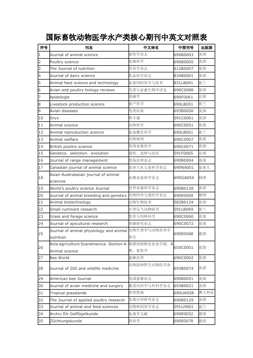
国际畜牧动物医学水产类核心期刊中英文对照表
序号
刊名
中文译名
中图刊号
出版国
1
Journal of animal science
畜牧学杂志
690B0003
美国
2
Poultry science
家禽科学
690B0005
美国
3
The Journal of nutrition
营养学杂志
612B0007
美国
4
Journal of dairy science
兽医诊断研究杂志
693B0086
美国
25
Canadian journal of veterinary research
加拿大兽医研究杂志
693NA051
加拿大
26
The Canadian veterinary journal
加拿大兽医杂志
693NA052
加拿大
27
Medical and veterinary entomology
1124-5352
意大利
Feed Compounder
831C0055
0950-771X
英国
Feed International
831B0070
0274-5771
美国
Feed Management
831B0060
0014-956X
美国
Grassland Science
690D0103
日本
Journal of Animal Science and Technology
世界家禽科学杂志
690B0128
美国
20
Journal of animal breeding and genetics
832B中文资料
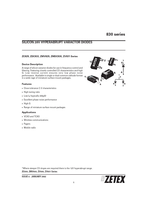
ZC829, ZDC833, ZMV829, ZMDC830, ZV831 Series Device DescriptionA range of silicon varactor diodes for use in frequency control and filtering.Featuring closely controlled CV characteristics and high Q.Low reverse current ensures very low phase noise performance.Available in single or dual common cathode format in a wide rage of miniature surface mount packages.Features·Close tolerance C-V characteristics ·High tuning ratio ·Low I R (typically 200pA)·Excellent phase noise performance ·High Q·Range of miniature surface mount packagesApplications·VCXO and TCXO·Wireless communications ·Pagers ·Mobile radio*Where steeper CV slopes are required there is the 12V hyperabrupt range.ZC930, ZMV930, ZV930, ZV931 Series 830 seriesISSUE 6 - JANUARY 20021SILICON 28V HYPERABRUPT VARACTOR DIODES830 seriesISSUE 6 - JANUARY 20022PARTCapacitance (pF)V R =2V,f=1MHzMin Q V R =3V f=50MHzCapacitance RatioC 2/C 20at f=1MHzMIN.NOM.MAX.MIN.MAX.829A 7.388.29.02250 4.3 5.8829B 7.798.28.61250 4.3 5.8830A 9.010.011.0300 4.5 6.0830B 9.510.010.5300 4.5 6.0831A 13.515.016.5300 4.5 6.0831B 14.2515.015.75300 4.5 6.0832A 19.822.024.2200 5.0 6.5832B 20.922.023.1200 5.0 6.5833A 29.733.036.3200 5.0 6.5833B 31.3533.034.65200 5.0 6.5834A 42.347.051.7200 5.0 6.5834B 44.6547.049.35200 5.0 6.5835A 61.268.074.8100 5.0 6.5835B 64.668.071.4100 5.0 6.5836A 90.0100.0110.0100 5.0 6.5836B95.0100.0105.0100 5.06.5TUNING CHARACTERISTICS at Tamb = 25°CPARAMETER SYMBOLMAX UNIT Forward currentI F 200mA Power dissipation at T amb =25ЊC SOT23P tot 330mW Power dissipation at T amb =25ЊC SOD323P tot 330mW Power dissipation at T amb =25ЊC SOD523P tot250mW Operating and storage temperature range-55to +150ЊCABSOLUTE MAXIMUM RATINGSPARAMETERCONDITIONS MIN.TYP.MAX.UNIT Reverse breakdown voltage I R =10uA 25V Reverse voltage leakageV R =20V 0.220nA Temperature coefficient of capacitanceV R =3V,f =1MHz300400ppCm/ЊCELECTRICAL CHARACTERISTICS at Tamb = 25°C830 seriesTYPICAL CHARACTERISTICSISSUE 6 - JANUARY 20023830 seriesISSUE 6 - JANUARY 20024O R D E R C O D E S A N D P A R T M A R K I N GR E E L C O D ER E E L S I Z ET A P E W I D T HQ U A N T I T Y P E R R E E LT A7i n c h (180m m )8m m3000T C13i n c h (330m m )8m m 10000T A P E A N D R E E L I N F O R M A T I O NT h e o r d e r c o d e s a r e s h o w n a s T A w h i c h i s f o r 7i n c h r e e l s .F o r 13i n c h r e e l s s u b s t i t u t e T C i n p l a c e o f T A i n t h e o r d e r c o d e .ISSUE 6 - JANUARY 20025830 seriesSOT23 PACKAGE DIMENSIONSSOD323 PACKAGE DIMENSIONSZetex plcFields New Road ChaddertonOldham, OL9 8NP United KingdomTelephone (44) 161 622 4422Fax: (44) 161 622 4420Zetex GmbHStreitfeldstraße 19D-81673 München GermanyTelefon: (49) 89 45 49 49 0Fax: (49) 89 45 49 49 49Zetex Inc700 Veterans Memorial Hwy Hauppauge, NY11788USATelephone: (631) 360 2222Fax: (631) 360 8222Zetex (Asia) Ltd3701-04Metroplaza, Tower 1Hing Fong Road Kwai Fong Hong KongTelephone: (852) 26100 611Fax: (852) 24250 494These offices are supported by agents and distributors in major countries world-wide.This publication is issued to provide outline information only which (unless agreed by the Company in writing)may not be used,applied or reproduced for any purpose or form part of any order or contract or be regarded as a representation relating to the products or services concerned.The Company reserves the right to alter without notice the specification,design,price or conditions of supply of any product or service.For the latest product information,log on to©Zetex plc 2001830 series6ISSUE 6 - JANUARY 2002DIM MILLIMETRES MIN.MAX A ᎏ0.800A10.0000.100A20.6000.800b10.1600.300c 0.0800.220D 0.7000.900E 1.500 1.700E1 1.100 1.300L 0.2000.400L10.1700.230⍜1Њ4Њ10ЊSOD523 PACKAGE DIMENSIONSSOD323 PACKAGE DIMENSIONS。
8312;中文规格书,Datasheet资料

Nominal data
Type 8312 VDC VDC min-1 W °C °C m3/h B dB(A) 12 6 .. 15 3300 2.6 -20 75 54 5.2 36
Nominal voltage Nominal voltage range Speed Power input Min. ambient temperature Max. ambient temperature Air flow Sound power level Sound pressure level
Connection line Locked-rotor protection Direction of rotation Direction of air flow Bearing Lifetime L10 at 40 °C Lifetime L10 at maximum temperature Mass Housing material Material of impeller Motor protection Approval
8312
DC axial compact fan
ebm-papst St. Georgen GmbH & Co. KG Hermann-Papst-Straße 1 D-78112 St. Georgen Phone +49 7724 81-0 Fax +49 7724 81-1309 info2@
ml = max. load · me = max. efficiency · rfa = running at free air · cs = customer specs · cu = customer unit Subject to alterations
sy8301abc中文规格书
sy8301abc中文规格书一、产品简介sy8301abc是一款高性能的数字信号处理芯片,具有多种功能和先进的技术特点。
该芯片广泛应用于各类电子产品中,包括智能手机、平板电脑、数码相机、无人机等。
二、技术特点1. 高速运算能力:sy8301abc芯片采用先进的数字信号处理技术,具有高速运算能力,能够实现复杂的信号处理算法。
2. 低功耗设计:该芯片采用先进的低功耗设计,有效延长电子产品的续航时间。
3. 宽工作电压范围:sy8301abc芯片能够适应不同的工作电压,具有较大的电压适应范围。
4. 多种接口支持:该芯片支持多种常见接口,包括I2C、SPI、UART 等,方便用户在不同系统中的应用。
5. 丰富的功能模块:sy8301abc芯片具有丰富的功能模块,包括AD 转换、数字滤波、时序控制等,能够满足不同应用的需求。
三、性能参数1. 工作频率:1GHz2. 工作电压:1.8V-3.3V3. 工作温度:-40℃~85℃4. 封装形式:QFN48四、应用领域sy8301abc芯片广泛应用于以下领域:1. 通信设备:包括基站、无线路由器、通信模块等。
2. 智能终端:智能手机、平板电脑、智能手表等。
3. 消费类电子产品:数码相机、音频设备、游戏机等。
4. 工业控制:工业自动化设备、传感器、运动控制系统等。
五、安全与可靠性sy8301abc芯片具有严格的安全与可靠性设计,能够满足各种复杂环境下的工作需求,具有较高的稳定性和可靠性。
六、结论sy8301abc是一款功能丰富、性能卓越的数字信号处理芯片,具有广泛的应用领域和可靠的安全性能,可为电子产品的设计提供强大的支持和保障。
期待sy8301abc芯片在各个领域得到更广泛的应用,为用户带来更好的产品体验。
七、市场前景随着科技的不断进步和消费电子产品的不断普及,数字信号处理芯片作为电子产品的核心部件之一,其市场需求也在不断增长。
sy8301abc作为一款性能卓越的芯片,具有广泛的应用领域和稳定可靠的特性,将会在未来的市场中拥有很好的发展前景。
834B中文资料
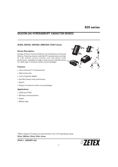
ZC829, ZDC833, ZMV829, ZMDC830, ZV831 Series Device DescriptionA range of silicon varactor diodes for use in frequency control and filtering.Featuring closely controlled CV characteristics and high Q.Low reverse current ensures very low phase noise performance.Available in single or dual common cathode format in a wide rage of miniature surface mount packages.Features·Close tolerance C-V characteristics ·High tuning ratio ·Low I R (typically 200pA)·Excellent phase noise performance ·High Q·Range of miniature surface mount packagesApplications·VCXO and TCXO·Wireless communications ·Pagers ·Mobile radio*Where steeper CV slopes are required there is the 12V hyperabrupt range.ZC930, ZMV930, ZV930, ZV931 Series 830 seriesISSUE 6 - JANUARY 20021SILICON 28V HYPERABRUPT VARACTOR DIODES830 seriesISSUE 6 - JANUARY 20022PARTCapacitance (pF)V R =2V,f=1MHzMin Q V R =3V f=50MHzCapacitance RatioC 2/C 20at f=1MHzMIN.NOM.MAX.MIN.MAX.829A 7.388.29.02250 4.3 5.8829B 7.798.28.61250 4.3 5.8830A 9.010.011.0300 4.5 6.0830B 9.510.010.5300 4.5 6.0831A 13.515.016.5300 4.5 6.0831B 14.2515.015.75300 4.5 6.0832A 19.822.024.2200 5.0 6.5832B 20.922.023.1200 5.0 6.5833A 29.733.036.3200 5.0 6.5833B 31.3533.034.65200 5.0 6.5834A 42.347.051.7200 5.0 6.5834B 44.6547.049.35200 5.0 6.5835A 61.268.074.8100 5.0 6.5835B 64.668.071.4100 5.0 6.5836A 90.0100.0110.0100 5.0 6.5836B95.0100.0105.0100 5.06.5TUNING CHARACTERISTICS at Tamb = 25°CPARAMETER SYMBOLMAX UNIT Forward currentI F 200mA Power dissipation at T amb =25ЊC SOT23P tot 330mW Power dissipation at T amb =25ЊC SOD323P tot 330mW Power dissipation at T amb =25ЊC SOD523P tot250mW Operating and storage temperature range-55to +150ЊCABSOLUTE MAXIMUM RATINGSPARAMETERCONDITIONS MIN.TYP.MAX.UNIT Reverse breakdown voltage I R =10uA 25V Reverse voltage leakageV R =20V 0.220nA Temperature coefficient of capacitanceV R =3V,f =1MHz300400ppCm/ЊCELECTRICAL CHARACTERISTICS at Tamb = 25°C830 seriesTYPICAL CHARACTERISTICSISSUE 6 - JANUARY 20023830 seriesISSUE 6 - JANUARY 20024O R D E R C O D E S A N D P A R T M A R K I N GR E E L C O D ER E E L S I Z ET A P E W I D T HQ U A N T I T Y P E R R E E LT A7i n c h (180m m )8m m3000T C13i n c h (330m m )8m m 10000T A P E A N D R E E L I N F O R M A T I O NT h e o r d e r c o d e s a r e s h o w n a s T A w h i c h i s f o r 7i n c h r e e l s .F o r 13i n c h r e e l s s u b s t i t u t e T C i n p l a c e o f T A i n t h e o r d e r c o d e .ISSUE 6 - JANUARY 20025830 seriesSOT23 PACKAGE DIMENSIONSSOD323 PACKAGE DIMENSIONSZetex plcFields New Road ChaddertonOldham, OL9 8NP United KingdomTelephone (44) 161 622 4422Fax: (44) 161 622 4420Zetex GmbHStreitfeldstraße 19D-81673 München GermanyTelefon: (49) 89 45 49 49 0Fax: (49) 89 45 49 49 49Zetex Inc700 Veterans Memorial Hwy Hauppauge, NY11788USATelephone: (631) 360 2222Fax: (631) 360 8222Zetex (Asia) Ltd3701-04Metroplaza, Tower 1Hing Fong Road Kwai Fong Hong KongTelephone: (852) 26100 611Fax: (852) 24250 494These offices are supported by agents and distributors in major countries world-wide.This publication is issued to provide outline information only which (unless agreed by the Company in writing)may not be used,applied or reproduced for any purpose or form part of any order or contract or be regarded as a representation relating to the products or services concerned.The Company reserves the right to alter without notice the specification,design,price or conditions of supply of any product or service.For the latest product information,log on to©Zetex plc 2001830 series6ISSUE 6 - JANUARY 2002DIM MILLIMETRES MIN.MAX A ᎏ0.800A10.0000.100A20.6000.800b10.1600.300c 0.0800.220D 0.7000.900E 1.500 1.700E1 1.100 1.300L 0.2000.400L10.1700.230⍜1Њ4Њ10ЊSOD523 PACKAGE DIMENSIONSSOD323 PACKAGE DIMENSIONS。
stm32f103中文资料

深圳市迪通科技有限公司 TEL:0755-83312947 83313941 83317488FAX:0755-83311568
STM32F103x8, STM32F103xB数据手册
目录
1 介绍......................................................................................................................................................... 4 2 规格说明.................................................................................................................................................. 5
− 2个看门狗定时器(独立的和窗口型的) − 系统时间定时器:24位自减型计数器
■ 多达9个通信接口 − 多达2个I2C接口(支持SMBus/PMBus) − 多达3个USART接口(支持ISO7816接口, LIN,IrDA接口和调制解调控制) − 多达2个SPI接口(18M位/秒) − CAN接口(2.0B 主动) − USB 2.0全速接口
2.3.1 ARM®的Cortex™-M3核心并内嵌闪存和SRAM .................................................................. 6 2.3.2 内置闪存存储器....................................................................................
可控硅参数说明及中英文对照表

VDRM
Repetitive peak off-state voltage
断态重复峰值电压
断态重复峰值电压是在门极断路而结温为额定值时,允许重复加在器件上的正向峰值电压.国标规定重复频率为50H,每次持续时间不超高10ms。规定断态重复峰值电压DRM为断态不重复峰值电压(即断态最大瞬时电压)UDSM的90%.断态不重复峰值电压应低于正向转折电压bo,所留裕量大小由生产厂家自行规定。UU
A
IGM
Forward Peak Gate Current
门极峰值电流
-
A
I2T
Circuit Fusing Consideration
周期电流平方时间积
-
A2ses
dIT/dt
Repetitive rate of rise of on-state current after triggering (IGT1~IGT3)
mA
IH
Holding Current
维持电流
维持可控硅维持通态所必需的最小主电流,它与结温有关,结温越高,则IH越小。
mA
IL
Latching Current (IGT3)
接入电流(第三象限)/擎住电流
擎住电流是晶闸管刚从断态转入通态并移除触发信号后,能维持导通所需的最小电流。对同一晶闸管来说,通常IL约为IH的2--4倍。
mA
ID
Off-state leakage current
断态漏电流
-
mA
VGT
Triggering gate voltage
门极触发电压
—可以选择Vgt 25度时max值的β倍。β为门极触发电压—结温特性系数,查数据手册可得,取特性曲线中最低工作温度时的系数。若对器件工作环境温度无特殊需要,通常选择时β取1~倍即可。
B8313
s Unbalanced to unbalanced operation s Very low insertion attenuation s High out of band selectivity s Low amplitude ripple s Filter impedance 50 Ω s No matching network required for operation at 50 Ω
S_6001
RoHS-compatible means that products are compatible with the requirements according to Art. 4 (substance restrictions) of Directive 2011/65/EU of the European Parliament and of the Council of June 8th, 2011, on the restriction of the use of certain hazardous substances in electrical and electronic equipment ("Directive") with due regard to the application of exemptions as per Annex III of the Directive in certain cases.
Moldability Matching coils
AD8318中文资料
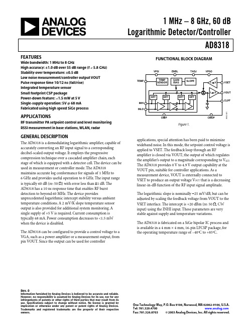
The AD8318 is fabricated on a SiGe bipolar IC process and is available in a 4 mm × 4 mm, 16-pin LFCSP package, for the operating temperature range of –40oC to +85oC.
Basic Connections ................................................................... 12 Enable ........................................................................................ 12 Input Signal Coupling ............................................................. 12 Output Interface....................................................................... 13 Setpoint Interface..................................................................... 13 Temperature Compensation of Output Voltage .................. 13 Temperature Sensor................................................................. 14
835A中文资料

ZC829, ZDC833, ZMV829, ZMDC830, ZV831 Series Device DescriptionA range of silicon varactor diodes for use in frequency control and filtering.Featuring closely controlled CV characteristics and high Q.Low reverse current ensures very low phase noise performance.Available in single or dual common cathode format in a wide rage of miniature surface mount packages.Features·Close tolerance C-V characteristics ·High tuning ratio ·Low I R (typically 200pA)·Excellent phase noise performance ·High Q·Range of miniature surface mount packagesApplications·VCXO and TCXO·Wireless communications ·Pagers ·Mobile radio*Where steeper CV slopes are required there is the 12V hyperabrupt range.ZC930, ZMV930, ZV930, ZV931 Series 830 seriesISSUE 6 - JANUARY 20021SILICON 28V HYPERABRUPT VARACTOR DIODES830 seriesISSUE 6 - JANUARY 20022PARTCapacitance (pF)V R =2V,f=1MHzMin Q V R =3V f=50MHzCapacitance RatioC 2/C 20at f=1MHzMIN.NOM.MAX.MIN.MAX.829A 7.388.29.02250 4.3 5.8829B 7.798.28.61250 4.3 5.8830A 9.010.011.0300 4.5 6.0830B 9.510.010.5300 4.5 6.0831A 13.515.016.5300 4.5 6.0831B 14.2515.015.75300 4.5 6.0832A 19.822.024.2200 5.0 6.5832B 20.922.023.1200 5.0 6.5833A 29.733.036.3200 5.0 6.5833B 31.3533.034.65200 5.0 6.5834A 42.347.051.7200 5.0 6.5834B 44.6547.049.35200 5.0 6.5835A 61.268.074.8100 5.0 6.5835B 64.668.071.4100 5.0 6.5836A 90.0100.0110.0100 5.0 6.5836B95.0100.0105.0100 5.06.5TUNING CHARACTERISTICS at Tamb = 25°CPARAMETER SYMBOLMAX UNIT Forward currentI F 200mA Power dissipation at T amb =25ЊC SOT23P tot 330mW Power dissipation at T amb =25ЊC SOD323P tot 330mW Power dissipation at T amb =25ЊC SOD523P tot250mW Operating and storage temperature range-55to +150ЊCABSOLUTE MAXIMUM RATINGSPARAMETERCONDITIONS MIN.TYP.MAX.UNIT Reverse breakdown voltage I R =10uA 25V Reverse voltage leakageV R =20V 0.220nA Temperature coefficient of capacitanceV R =3V,f =1MHz300400ppCm/ЊCELECTRICAL CHARACTERISTICS at Tamb = 25°C830 seriesTYPICAL CHARACTERISTICSISSUE 6 - JANUARY 20023830 seriesISSUE 6 - JANUARY 20024O R D E R C O D E S A N D P A R T M A R K I N GR E E L C O D ER E E L S I Z ET A P E W I D T HQ U A N T I T Y P E R R E E LT A7i n c h (180m m )8m m3000T C13i n c h (330m m )8m m 10000T A P E A N D R E E L I N F O R M A T I O NT h e o r d e r c o d e s a r e s h o w n a s T A w h i c h i s f o r 7i n c h r e e l s .F o r 13i n c h r e e l s s u b s t i t u t e T C i n p l a c e o f T A i n t h e o r d e r c o d e .ISSUE 6 - JANUARY 20025830 seriesSOT23 PACKAGE DIMENSIONSSOD323 PACKAGE DIMENSIONSZetex plcFields New Road ChaddertonOldham, OL9 8NP United KingdomTelephone (44) 161 622 4422Fax: (44) 161 622 4420Zetex GmbHStreitfeldstraße 19D-81673 München GermanyTelefon: (49) 89 45 49 49 0Fax: (49) 89 45 49 49 49Zetex Inc700 Veterans Memorial Hwy Hauppauge, NY11788USATelephone: (631) 360 2222Fax: (631) 360 8222Zetex (Asia) Ltd3701-04Metroplaza, Tower 1Hing Fong Road Kwai Fong Hong KongTelephone: (852) 26100 611Fax: (852) 24250 494These offices are supported by agents and distributors in major countries world-wide.This publication is issued to provide outline information only which (unless agreed by the Company in writing)may not be used,applied or reproduced for any purpose or form part of any order or contract or be regarded as a representation relating to the products or services concerned.The Company reserves the right to alter without notice the specification,design,price or conditions of supply of any product or service.For the latest product information,log on to©Zetex plc 2001830 series6ISSUE 6 - JANUARY 2002DIM MILLIMETRES MIN.MAX A ᎏ0.800A10.0000.100A20.6000.800b10.1600.300c 0.0800.220D 0.7000.900E 1.500 1.700E1 1.100 1.300L 0.2000.400L10.1700.230⍜1Њ4Њ10ЊSOD523 PACKAGE DIMENSIONSSOD323 PACKAGE DIMENSIONS。
829B中文资料

ZC829, ZDC833, ZMV829, ZMDC830, ZV831 Series Device DescriptionA range of silicon varactor diodes for use in frequency control and filtering.Featuring closely controlled CV characteristics and high Q.Low reverse current ensures very low phase noise performance.Available in single or dual common cathode format in a wide rage of miniature surface mount packages.Features·Close tolerance C-V characteristics ·High tuning ratio ·Low I R (typically 200pA)·Excellent phase noise performance ·High Q·Range of miniature surface mount packagesApplications·VCXO and TCXO·Wireless communications ·Pagers ·Mobile radio*Where steeper CV slopes are required there is the 12V hyperabrupt range.ZC930, ZMV930, ZV930, ZV931 Series 830 seriesISSUE 6 - JANUARY 20021SILICON 28V HYPERABRUPT VARACTOR DIODES830 seriesISSUE 6 - JANUARY 20022PARTCapacitance (pF)V R =2V,f=1MHzMin Q V R =3V f=50MHzCapacitance RatioC 2/C 20at f=1MHzMIN.NOM.MAX.MIN.MAX.829A 7.388.29.02250 4.3 5.8829B 7.798.28.61250 4.3 5.8830A 9.010.011.0300 4.5 6.0830B 9.510.010.5300 4.5 6.0831A 13.515.016.5300 4.5 6.0831B 14.2515.015.75300 4.5 6.0832A 19.822.024.2200 5.0 6.5832B 20.922.023.1200 5.0 6.5833A 29.733.036.3200 5.0 6.5833B 31.3533.034.65200 5.0 6.5834A 42.347.051.7200 5.0 6.5834B 44.6547.049.35200 5.0 6.5835A 61.268.074.8100 5.0 6.5835B 64.668.071.4100 5.0 6.5836A 90.0100.0110.0100 5.0 6.5836B95.0100.0105.0100 5.06.5TUNING CHARACTERISTICS at Tamb = 25°CPARAMETER SYMBOLMAX UNIT Forward currentI F 200mA Power dissipation at T amb =25ЊC SOT23P tot 330mW Power dissipation at T amb =25ЊC SOD323P tot 330mW Power dissipation at T amb =25ЊC SOD523P tot250mW Operating and storage temperature range-55to +150ЊCABSOLUTE MAXIMUM RATINGSPARAMETERCONDITIONS MIN.TYP.MAX.UNIT Reverse breakdown voltage I R =10uA 25V Reverse voltage leakageV R =20V 0.220nA Temperature coefficient of capacitanceV R =3V,f =1MHz300400ppCm/ЊCELECTRICAL CHARACTERISTICS at Tamb = 25°C830 seriesTYPICAL CHARACTERISTICSISSUE 6 - JANUARY 20023830 seriesISSUE 6 - JANUARY 20024O R D E R C O D E S A N D P A R T M A R K I N GR E E L C O D ER E E L S I Z ET A P E W I D T HQ U A N T I T Y P E R R E E LT A7i n c h (180m m )8m m3000T C13i n c h (330m m )8m m 10000T A P E A N D R E E L I N F O R M A T I O NT h e o r d e r c o d e s a r e s h o w n a s T A w h i c h i s f o r 7i n c h r e e l s .F o r 13i n c h r e e l s s u b s t i t u t e T C i n p l a c e o f T A i n t h e o r d e r c o d e .ISSUE 6 - JANUARY 20025830 seriesSOT23 PACKAGE DIMENSIONSSOD323 PACKAGE DIMENSIONSZetex plcFields New Road ChaddertonOldham, OL9 8NP United KingdomTelephone (44) 161 622 4422Fax: (44) 161 622 4420Zetex GmbHStreitfeldstraße 19D-81673 München GermanyTelefon: (49) 89 45 49 49 0Fax: (49) 89 45 49 49 49Zetex Inc700 Veterans Memorial Hwy Hauppauge, NY11788USATelephone: (631) 360 2222Fax: (631) 360 8222Zetex (Asia) Ltd3701-04Metroplaza, Tower 1Hing Fong Road Kwai Fong Hong KongTelephone: (852) 26100 611Fax: (852) 24250 494These offices are supported by agents and distributors in major countries world-wide.This publication is issued to provide outline information only which (unless agreed by the Company in writing)may not be used,applied or reproduced for any purpose or form part of any order or contract or be regarded as a representation relating to the products or services concerned.The Company reserves the right to alter without notice the specification,design,price or conditions of supply of any product or service.For the latest product information,log on to©Zetex plc 2001830 series6ISSUE 6 - JANUARY 2002DIM MILLIMETRES MIN.MAX A ᎏ0.800A10.0000.100A20.6000.800b10.1600.300c 0.0800.220D 0.7000.900E 1.500 1.700E1 1.100 1.300L 0.2000.400L10.1700.230⍜1Њ4Њ10ЊSOD523 PACKAGE DIMENSIONSSOD323 PACKAGE DIMENSIONS。
FT830A规格书
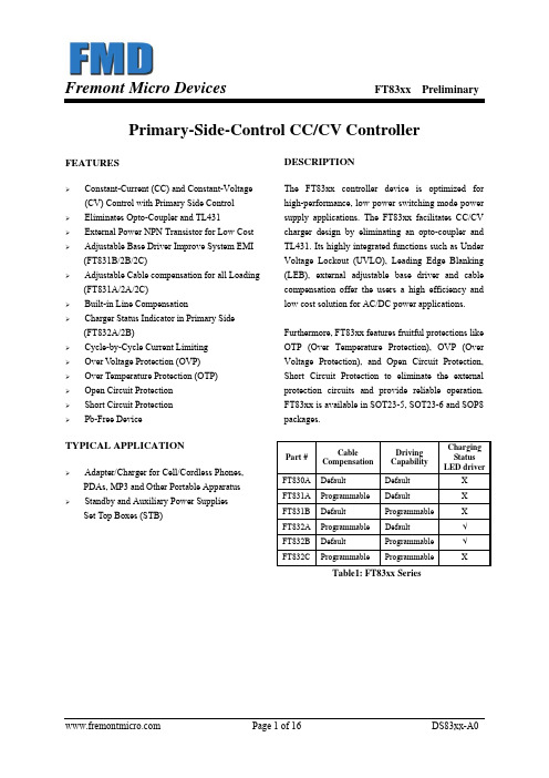
Furthermore, FT83xx features fruitful protections like OTP (Over Temperature Protection), OVP (Over Voltage Protection), and Open Circuit Protection, Short Circuit Protection to eliminate the external protection circuits and provide reliable operation. FT83xx is available in SOT23-5, SOT23-6 and SOP8 packages.
DESCRIPTION
The FT83xx controller device is optimized for high-performance, low power switching mode power supply applications. The FT83xx facilitates CC/CV charger design by eliminating an opto-coupler and TL431. Its highly integrated functions such as Under Voltage Lockout (UVLO), Leading Edge Blanking (LEB), external adjustable base driver and cable compensation offer the users a high efficiency and low cost solution for AC/DC power applications.
Hale Waihona Puke Part #Cable Compensation
MA44631B中文资料
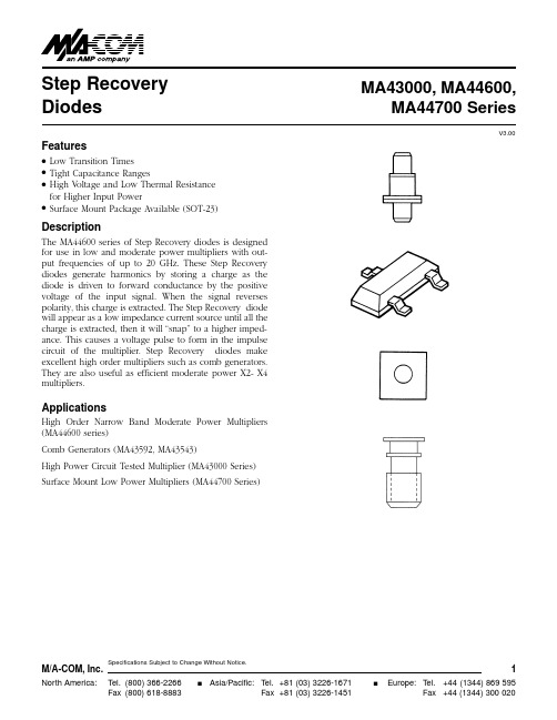
V3.00Step Recovery DiodesMA43000,MA44600,MA44700 SeriesFeaturesq Low Transition Times q Tight Capacitance RangesqHigh Voltage and Low Thermal Resistance for Higher Input PowerqSurface Mount Package Available (SOT-23)DescriptionThe MA44600 series of Step Recovery diodes is designed for use in low and moderate power multipliers with out-put frequencies of up to 20 GHz. These Step Recovery diodes generate harmonics by storing a charge as the diode is driven to forward conductance by the positive voltage of the input signal. When the signal reverses polarity, this charge is extracted. The Step Recovery diode will appear as a low impedance current source until all the charge is extracted, then it will “snap” to a higher imped-ance. This causes a voltage pulse to form in the impulse circuit of the multiplier. Step Recovery diodes make excellent high order multipliers such as comb generators.They are also useful as efficient moderate power X2- X4multipliers.ApplicationsHigh Order Narrow Band Moderate Power Multipliers (MA44600 series)Comb Generators (MA43592, MA43543)High Power Circuit Tested Multiplier (MA43000 Series)Surface Mount Low Power Multipliers (MA44700 Series)V3.00 Electrical Specifications @ 25°CSnap VaractorsNotes:1.When ordering, specify the desired case style by adding the case des-ignation as a suffix to the model number.Case styles for the MA44600series are 30, 91 and 93.To order in chip form, add the suffix “134”tothe model number.The nominal chip size for the MA44600 series is15 mils.2.Reverse voltage (V R) is measured at a reverse bias current of 10 µA.3.Junction capacitance is measured at a reverse voltage of 6 volts and afrequency of 1 MHz.4.Transition time is measured between 20% and 80% points on the volt-age recovery trace.Test conditions are +10 mA and -10 volts. Case Styles (See appendix for complete dimensions)309193134Notes:1.The standard case styles are indicated for each model number.Other case styles are available.Consult the factory for information.High Power Circuit Tested Step Recovery DiodesMin./Max.3Junction Min./Max.Maximum Maximum CapacitanceLifetime,T L Snap Time,T S Thermal Model C j 10 mA/6 mA-10V/10 mAResistance,jcNumber (pF)(ns)(ps)(C/W)MA43000 3 - 4.50250 - 50060012MA43002 1.60 - 2.4075 - 22525025MA430040.45 - 0.8520 - 5015045Surface Mount Step Recovery Diodes (SOT-23)2.Reverse voltage is measured at reverse bias current of 10 µA.3.Junction capacitance is measured at a reverse bias of 6 volts and a frequency of 1 MHz.Case styles (See appendix for complete dimensions)91103SOT -23 (High Profile)Notes:1.The standard case styles are indicated for each model number.For other available case styles, consult the factory.2.This is an operable output frequency range and does not imply instan-taneous bandwidth.Min./Max.4Maximum 2Min./Max.3Junction Min./Max.Maximum Maximum Nominal 2Input Reverse CapacitanceCarrier Snap Time,T S Thermal Output Model Case 1Power Voltage V R Cj Lifetime,T L-10V/10 mAResistance Frequency Number Style (Watts)(Volts)(pF)(ps)(ps)jc(C/W)(GHz)MA4359230 1.025 - 400.2 - 0.309 - 279070 1 - 12MA43543931.520 - 500.2 - 0.5510 - 25601252 - 20Absolute Maximum Ratings @ 25°CEnvironmental PerformanceThe MA44600 and MA43000 series of diodes in ceramic packages are capable of meeting the tests dictated by the methods and procedures of the latest revisions of MIL-S-19500, MIL-STD-202 and MIL-STD-750 which specify mechanical, electrical, thermal and other environmental tests common to military semiconductor products.High Order Step Recovery Diode Varactors for Use in Comb GenerationCase Styles (See appendix for complete dimensions)3.Breakdown voltage is measured at a reverse bias voltage of 10 µA.4.Junction capacitance is measured at a reverse bias voltage of 6 volts and a frequency of 1 MHz.3093。
8B10B中文资料

Ma y 20001© 2000 Actel Corporationv2.08b10b MacroProduct Sum m ary•Gigabit Ethernet 8b10b Function •125 MHz Operation•Transmit and Receive Function •Disparity and Illegal Code Error Checking•Connects directly to industry-standard Gigabit Ethernet Transceiver devices.•Supports either single or dual channel transceiver in a single device.Versi onThis data sheet defines the functionality of Version 1.0 of the 8b10b macro.General D escripti onThe 8b10b macro implements the function for the physical coding sublayer for Gigabit Ethernet as defined in the IEEE 802.3z specification. The 8b10b is a marriage of two sub-blocks, the 5b6b and the 3b4b encoder/decoders (ENDECs). The purpose of the ENDEC is to convert 8-bit datainto a 10-bit code that contains an equal number of 0’s and 1’s. In addition, the code is built so that no more than five consecutive 0’s or 1’s are ever transmitted. The 8b10b macro is designed to work with a variety of standard transceiver devices. A set of generic signals provides a data and command interface with the system logic. A system-level block diagram describing the use of the 8b10b macro is shown in Figure 1.The 8b10b macro provides a user interface and a transceiver interface. The user interface consists of transmit data,receive data, and several control and status signals used to qualify the data. To simplify the timing of the user interface,the data transmission is word-wide (16-bits) and operates at 62.5 MHz. This strategy provides a simplified timing interface for system logic yet still meets the 125 megabyte per second requirements for Gigabit Ethernet.The transceiver interface is designed to connect directly to most commercially-available Gigabit Ethernet transceiver devices. The transceiver is responsible for serializing transmit data and deserializing receive data. In addition, the receiver is designed to resynchronize the serial stream whenever an external device detects illegal coding errors.Figure 1•System Block Diagram Depicting 8b10b Macro Usage28b10b Dev ice RequirementsPerformance requirements of the 8b10b macro drives device selection. Table 1 defines the minimum device requirements for the A54SXA family.I/O Signal Des criptionsThe 8b10b macro signals are defined in Tables 2 and 3. 8b10b Trans m itter Detailed OperationThe 8b10b transmitter is a pipelined structure that converts 16-bit command or data information into two 10-bit encoded values. Command and data information are qualified by the TX_K_CHAR[1:0] bus. TX_K_CHAR[1] corresponds to the upper data byte on TX_WORD[15:0] and TX_K_CHAR[0] is for the lower byte. The data on the TX_WORD bus is continuously registered into the transmitter; however, this data is only transferred to the encoder when the TX_WRn signal is driven low for a single cycle. The transmitter will encode and send the upper byte first followed by the lower byte. Because of the pipelined nature of the transmitter, the first encoded data will be driven on the TX_DATA bus several cycles after the TX_WRn pulse. All data input information is valid, though command possibilities are limited. If the transmitter detects a bad command, then it will assert the INVALID_K signal. When the TX_WRn input is inactive, the transmitter will continuously send an IDLE2 (K28.5/D16.2)command defined in the 802.3 specification. Figure 2on page 3 illustrates the implementation of the transmitter function.The core of the transmitter consists of a data encoder, a command encoder, and a disparity calculator. Each encoder calculates a 4B and 6B code for the input data. The correct code, command or data, is then selected based on the original input value of TX_K_CHAR. The disparity calculatordetermines whether encoded values need to be inverted to maintain the correct running disparity. Finally, the code is registered and sent to the transceiver on the TX_DATA bus.8b10b Receiv er D etailed OperationThe 8b10 receiver is also a pipelined structure that converts two 10-bit encoded values qualified by the clocks RBC0 and RBC1 and converts them to 16-bit command or data information. Command information is indicated by the RX_K_CHAR[1:0] bus signals asserted high. The data on the upper byte of the RX_WORD bus is the first decoded value in the sequence.Several signals qualify the validity of the information on RX_WORD. RX_WORD contains good information whenever CODE_ERRORn is inactive (high) and WORD_SYN Cn is active (low). If WORD_SYN Cn is high or CODE_ERRORn is low, this indicates some problem in transmission. Whenever the receiver loses sync (WORD_SYNCn is high), it asserts the COMMA_DET_E Noutput so that the transceiver resynchronizes the data on subsequent K28.5 commands.When sync is reestablished, the WORD_SYNCn will again be driven low after the pipeline has been flushed of potentially bad data. Figure 3on page 4 illustrates the implementation of the 8b10b receive function.Receive data is first loaded into two parallel registers. The first register is active on the rising edge of RBC0 and the second on the rising edge of RBC1. The RBC0 data is thenTable 1•Device Statistics for the 8b10b MacroDevice Speed Grade Utilization A54SX08A Standard 96%A54SX16A Standard48%A54SX32A-124%Table 2•Transceiver Interface SignalsName 1Type DescriptionCOMMA_DETECTInputActive high pulse from the transceiver indicating that a comma character has been detected and the received data is aligned with the rising edge of the RBC1clock.RBC0,RBC1Input Clock signals recovered from the received data stream.These clocks are 180degrees out of phase and the rising edge of each clock qualifies receive data.RX_DA TA[9:0]Input 10-bit encoded input data from the transceiver qualified by the rising edges of RBC0and RBC1.COMMA_DET_ENOutputActive high signal indicating that the transceiver should align the data stream with the rising edge of RBC1.This output is asserted when the 8b10b detects multiple consecutive encoding errors.TX_DA TA[9:0]Output10-bit encoded output data to the transceiver.Note:1.Active LOW signals are designated with a trailing lower-case n.38b10b M a croresynchronized with RBC1 on the next RBC1 rising clock edge. From this point, the two codes are decoded in parallel and move from stage to stage based on the RBC1 clock input.The error check block monitors the incoming codes and checks for illegal codes and/or bad running disparity. Whenan error in the 8b10b code is detected, the CODE_ERRORn is asserted. If several codes in a row are received with errors,then the 8b10b will assume that synchronization with the transceiver has been lost and will deactivate WORD_SYNCn and assert the COMMA_DET_EN signal. The number ofTable 3•System Interface SignalsName 1Type DescriptionCLK125Input Primary 125MHz clock signal for the transmit block of the 8b10b macro.RSTnInput Asynchronous reset signal for the macro.TX_K_CHAR[1:0]InputActive high signal indicating that the TX_WORD[15:0]contains command informa-tion.Bit 0corresponds to the lower byte (bits 7:0)and bit 1corresponds to the upper byte (bits 15:8)of TX_WORD.TX_WORD[15:0]Input 16-bit input data to the transmitter.Byte 1is transmitted first followed by byte 0.TX_WRnInputActive low signal that qualifies the TX_WORD data.When this signal is asserted,the data defined on TX_WORD will be registered into the 8b10b macro,encoded,and sent to the transceiver intwo consecutive 10-bit transfers.CODE_ERRORn[1:0]OutputActive low signal indicating that the ENDEC has detected an error in the received data stream.Bit 0corresponds to the lower byte (bits 7:0)and bit 1corresponds to the upper byte (bits 15:8)of RX_WORD.INVALID_K OutputActive high signal indicating that the upstream device requested the ENDEC to transmit an invalid command character.This signal is asserted when either of the TX_K_CHAR[1:0]is active,but the associated don on the byte lane of TX_WORD[15:0]does not correspond to a valid command character.RX_CLKOutput The receive clock.The rising edge of this clock qualifies RX_WORD[15:0],RX_K_CHAR[1:0],WORD_SYNCn,and CODE_ERRORn[1:0].RX_K_CHAR[1:0]Output Output from the ENDEC to the transceiver indicating that the received data is a command code.RX_WORD[15:0]Output 16-bit decoded receive data.The upper byte was received first and the lower byte was received second in the data sequence.WORD_SYNCnOutputActive low signal indicating that the received data is correctly aligned.Note:1.Active LOW signals are designated with a trailing lower-case n.Figure 2•8b10b Transmitter Block Diagram4consecutive errors required to force a resynchronization is programmable, from 2 to 16 (default is 6). The transceiver then resynchronizes the data on the rising edge of RBC1 using K28.5 codes. A pulse on the COMMA_DETECT input indicatesthat the transceiver has reacquired sync. The 8b10b responds by deasserting COMMA_DET_E Nand asserting WORD_SYNCn.Figure 3•8b10b Receiver Block Diagram58b10b M a croHierarchy of the 8b10b M odelThe hierarchy of the 8b10b model is shown in Figure 4. The transmitter is the encoder. The encoder is subdivided into the data encoder (enc_d), command encoder (enc_k), and the running disparity calculator (enc_flip). The enc_d is composed of the mux32x6, mux32x1, and mux4x1 modules that create a ROM for data encoding. The receiver is the decoder, which is subdivided into the data decoder (dec_data), running disparity decoder (dec_rd), and the synchronization state machine (sync_fsm).Utiliz ation StatisticsThe 8b10b macro uses approximately 250 sequential modules and 350 combinatorial modules in the A54SX-A devices. The macro also uses approximately 70 I/Os and requires two clock networks for the CLK125 and RBC1 inputs. Because of the light loading, the clock input RBC0 can use a regular input. It is possible to implement a dual channel 8b10b in either the A54SX16A or A54SX32A device.Sy stem Tim ingThe 8b10b macro is divided into two functions, the transmitter and the receiver. The transmitter is designed to operate at 125 MHz, the receiver at 62.5 MHz. The input setup time for transmitter signals (TX_WORD, TX_K_CHAR, and TX_WRn) are measured with respect to the rising edge of CLK125. The input setup time for the receiver signal RX_DATA is measured with respect to the rising edge of both RBC0 and RBC1. The input setup time for the COMMA_DETECT signal is measured with respect to RBC1only. Receiver output timing is defined with respect to the rising edge of RX_CLK, an inverted version of RBC1 (refer to Figure 5 and Figure 6).Table 4 defines the internal register-to-register delays for the CLK125MHZ domain (transmitter) and the RBC1 domain (receiver). RBC0 domain to RBC1 domain timing is providedfor reference. Input setup requirements are defined in Table 5. Output valid times are defined in Table 6 and Table 7.8B10B W aveform sThe operation of the 8b10b macro is illustrated in the following waveforms. The function of the 8b10b can be illustrated using 5 different waveforms:•Normal transmission•Transmission with an invalid K command •Normal receive•Loss of synchronization with the transceiver •Synchronization with the transceiverFigure 4•Hierarchy of the 8b10b ENDEC.Figure 5•Input Timing for 8b10b SignalsFigure 6•Output Timing for 8b10b Signals Table 4•Internal Reg-Reg Delays (ns max)Name SX08A SX16A SX32A-1CLK125MHZ 7.57.57.0RBC113.515.012.5RBC0->RBC12.02.02Notes:1.All timing is for worst-case commercial conditions.2.Expected values from commercially available synthesis toolsusing standard design practices.6A normal transmission begins by placing valid data/command information on TX_WORD and TX_K_CHAR while simultaneously asserting the TX_WRn signal. After several cycles, the encoded data is driven onto the TX_DATA bus. If command information is illegal, the IN VALID_K signal will assert for one cycle. Normal 8b10b transmission is illustrated in Figure 7 and an invalid command waveform is shown in Figure 8on page 7.A normal receive assumes that the 8b10b encoded data on RX_DATA is aligned with RBC1. Encoded data is registered into the 8b10b off the rising edge of both RBC1 and RBC0.After several cycles, the unencoded data or command isdriven onto the RX_WORD and RX_K_CHAR buses. Thisinformation is qualified by the rising edge of RX_CLK. Thenormal 8b10b receive is depicted in Figure 9on page 7.In some cases, the 8b10b detects an error condition on the incoming data stream. When this occurs, the output CODE_ERRORn is asserted. If several consecutive errors are found, the 8b10b will assume that it has lost synchronization with the transceiver and will attempt to resynchronize by asserting the COMMA_DET_E Noutput as shown in Figure 10on page 7.When the COMMA_DET_E output is asserted, the transceiver will scan the incoming data stream for a K28.5command code and will resynchronize RX_DATA on the rising edge of RBC1. If the data stream is synchronized and a K28.5command is detected, then the transceiver will indicate synchronization by asserting the COMMA_DETECT signal.After two pulses, the 8b10b will again be synchronized as indicated by the WORD_SYNCn signal in Figure 11on page 8.Table 5• Input Required Set-Up Times (ns max)NameSX08A SX16A SX32A-1COMMA_DETECT 0.50.50.5RX_DA TA[9:0] 1.0 1.00.5TX_WRn 0.50.50.5TX_K_CHAR 1.0 1.00.5TX_WORD[15:0]1.01.00.5Notes:1.All timing is for worst-case commercial conditions.2.Expected va lues from commercia lly a va ila ble synthesis toolsusing standard design practices.Table 6•Output Valid Times (ns max)NameSX08A SX16A SX32A-1COMMA_DET_EN 6.0 6.0 6.0INVALID_K 6.0 6.0 6.0TX_DAT A[9:0] 5.5 5.5 5.5RX_CLK6.06.06.0Notes:1.All timing is for worst-case commercial conditions.2.Expected va lues from commercia lly a va ila ble synthesis toolsusing standard design practices.Table 7•Receive Data Valid Prior to RX_CLK (ns max)NameSX08A SX16A SX32A-1CODE_ERRORn 6.0 6.0 6.0RX_K_CHAR 6.0 6.0 6.0RX_WORD[15:0] 6.0 6.0 6.0WORD_SYNCn6.06.06.0Notes:1.All timing is for worst-case commercial conditions.2.Expected va lues from commercia lly a va ila ble synthesis toolsusing standard design practices.3.Hold times for all signals is at least 2ns after the rising edge ofRX_CLK.Figure 7•Normal Transmit8b10b M a croFigure 8•Invalid CommandFigure 9•Normal ReceiveFigure 10•Receive Error7Figure 11•Synchronization with the Transceiver 8Actel and the Actel logo are registered trademarks of Actel Corporation.All other trademarks are the property of their owners.Actel Europe Ltd.Daneshill House,Lutyens Close Basingstoke,Hampshire RG248AG United KingdomTel:+44-(0)125-630-5600Fax:+44-(0)125-635-5420Actel Corporation955East Arques AvenueSunnyvale,California94086USATel:(408)739-1010Fax:(408)739-1540Actel Asia-PacificEXOS Ebisu Bldg.4F1-24-14Ebisu Shibuya-kuT okyo150JapanTel:+81-(0)3-3445-7671Fax:+81-(0)3-3445-76685172155-0/5.00。
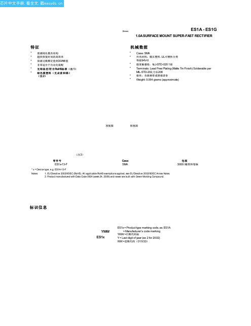
ES1B中文资料(Diodes)中文数据手册「EasyDatasheet - 矽搜」
公司产品是专门未经授权未经生命支持设备或系统的关键组件公司的
首席执行官的书面批准 .如本文所用:
A.生命支持设备或系统的设备或系统,其中:
生命保障
1.旨在植入到体内,或 2.支持或维持生命,其未履行正确使用时按照所提供的使用说明
机械数据
• Case: SMA • 外壳材料:模压塑料. UL可燃性分类
等级94V-0 • 湿度敏感度:每J-STD-020 1级 • Terminals: Lead Free Plating (Matte Tin Finish) Solderable per
MIL-STD-202,方法208 • 极性:负极频带或阴极诺奇 • Weight: 0.064 grams (approximate)
公司不保证或任何接受任何通过非授权渠道购买的任何产品承担任何责任 . 如果客户购买或使用Diodes公司产品的任何意外或未经授权的应用程序,客户应赔偿并Diodes公司及其代表的所有索赔,损害赔偿,费用和律师直接或间接引起 的,费用无害,人身伤害的任何索赔或与此类意外或未经授权的应用程序死亡.
本文描述的产品可能受一个或多个美国,国际或外国专利正在申请中.产品名称和标记.本文中也可以包含在一个或多个美国,国际或涉外商标.
A 2.29 2.92 B 4.00 4.60 C 1.27 1.63 D 0.15 0.31 E 4.80 5.59 G 0.05 0.20 H 0.76 1.52 J 2.01 2.30
在毫米所有尺寸
芯片中文手册,看全文,戳
建议焊盘布局
C
X
Y
G
Z
ES1A - ES1G
尺寸值(单位 mm)
Z
6.5
G
1.5
BAS321中文资料

MAM406
Fig.1 Simplified outline (SOD323) and symbol.
LIMITING VALUES In accordance with the Absolute Maximum Rating System (IEC 60134). SYMBOL VRRM VR IF IFRM IFSM PARAMETER repetitive peak reverse voltage continuous reverse voltage continuous forward current repetitive peak forward current non-repetitive peak forward current see Fig.2; note 1 tp < 0.5 ms; δ ≤ 0.25 square wave; Tj = 25 °C prior to surge; see Fig.4 t = 1 µs t = 100 µs t = 10 ms Ptot Tstg Tj Note 1. Device mounted on an FR4 printed circuit-board. total power dissipation storage temperature junction temperature Tamb = 25 °C; note 1 − − − − −65 − 9 3 1.7 300 +150 150 A A A mW °C °C CONDITIONS − − − − MIN. MAX. 250 200 250 625 V V mA mA UNIT
kn831b使用手册

kn831b使用手册摘要:一、前言二、KN831B 使用手册简介1.手册的目的和适用对象2.手册的结构和内容三、KN831B 设备概述1.设备外观和主要部件2.设备性能参数四、KN831B 操作步骤1.准备工作2.设备开启与关闭3.功能模块操作3.1 数据采集3.2 数据分析与处理3.3 数据存储与传输4.设备维护与故障排除五、KN831B 使用注意事项六、附录1.设备规格参数2.技术支持联系方式正文:【前言】KN831B 使用手册旨在帮助用户了解KN831B 设备的使用方法、操作步骤以及注意事项。
本手册适用于所有使用KN831B 的用户,包括设备操作人员和管理人员。
请在使用KN831B 之前,详细阅读本手册,以确保正确、安全地使用设备。
【KN831B 使用手册简介】本手册分为六个部分,分别是前言、KN831B 使用手册简介、KN831B 设备概述、KN831B 操作步骤、KN831B 使用注意事项和附录。
【KN831B 设备概述】KN831B 是一款集数据采集、分析和处理于一体的设备。
在外观方面,KN831B 采用紧凑的设计,便于携带和安装。
主要部件包括传感器、数据处理器、显示屏、操作按键等。
在性能参数方面,KN831B 具有高精度、高速度的数据采集能力,适用于各种复杂环境。
【KN831B 操作步骤】在操作KN831B 之前,请确保设备已经充满电,并安装相应的软件。
设备开启与关闭的步骤分别为:1.按下设备侧面的电源键,开启设备。
2.设备启动后,显示屏会显示设备型号和版本信息。
3.完成数据采集后,可按下设备侧面的确认键,保存数据并关闭设备。
功能模块操作包括数据采集、数据分析和处理、数据存储与传输。
具体操作步骤请参考设备使用说明书。
【设备维护与故障排除】设备维护方面,建议定期对设备进行清洁,避免灰尘和污垢影响设备性能。
如遇故障,请先按照设备使用说明书进行排查,如无法解决,请联系售后服务人员。
【KN831B 使用注意事项】1.在使用KN831B 时,请确保设备处于稳定的环境中,避免高温、潮湿、强磁场等恶劣条件。
Omron K8AB-PW三相过电压报警电源控制器说明书

Measuring & Monitoring Relay
English Instructions Manual
Thank you for purchasing an OMRON pridyct. In this Instructions Manual, you will find information about this product’s features, capabilities, and operating instructions. Please observe the following when using this product. ɾThis product is designed for use by qualified electrical engi
c All Rights Reserved
9419064-3 C
Precautions for Safe Use
Make sure to follow the instructions below to ensure safety.
1. Do not use or keep this product in the following environments.
install switches or circuit breakers that conform to relevant requirements of IEC60947-1 and IEC60947-3, and label them appropriately. 11. For DC input, use a SELV power-supply capable of overcurrent protection. Specifically, a SELV powersupply has a double or reinforced insulation for input and output, and output voltage of 30Vr.m.s with 42.4V at peak or DC60V maximum. Recommended power-supply : Model S8VS-06024˘ (Omron product) 12. Do not turn a setting volume beyond the scope of movement.
- 1、下载文档前请自行甄别文档内容的完整性,平台不提供额外的编辑、内容补充、找答案等附加服务。
- 2、"仅部分预览"的文档,不可在线预览部分如存在完整性等问题,可反馈申请退款(可完整预览的文档不适用该条件!)。
- 3、如文档侵犯您的权益,请联系客服反馈,我们会尽快为您处理(人工客服工作时间:9:00-18:30)。
ZC829, ZDC833, ZMV829, ZMDC830, ZV831 Series Device Description
A range of silicon varactor diodes for use in frequency control and filtering.Featuring closely controlled CV characteristics and high Q.Low reverse current ensures very low phase noise performance.Available in single or dual common cathode format in a wide rage of miniature surface mount packages.
Features
·Close tolerance C-V characteristics ·High tuning ratio ·Low I R (typically 200pA)
·Excellent phase noise performance ·High Q
·Range of miniature surface mount packages
Applications
·VCXO and TCXO
·Wireless communications ·Pagers ·Mobile radio
*Where steeper CV slopes are required there is the 12V hyperabrupt range.ZC930, ZMV930, ZV930, ZV931 Series 830 series
ISSUE 6 - JANUARY 2002
1
SILICON 28V HYPERABRUPT VARACTOR DIODES
830 series
ISSUE 6 - JANUARY 2002
2
PART
Capacitance (pF)V R =2V,f=1MHz
Min Q V R =3V f=50MHz
Capacitance Ratio
C 2/C 20at f=1MHz
MIN.
NOM.MAX.MIN.MAX.829A 7.388.29.02250 4.3 5.8829B 7.798.28.61250 4.3 5.8830A 9.010.011.0300 4.5 6.0830B 9.510.010.5300 4.5 6.0831A 13.515.016.5300 4.5 6.0831B 14.2515.015.75300 4.5 6.0832A 19.822.024.2200 5.0 6.5832B 20.922.023.1200 5.0 6.5833A 29.733.036.3200 5.0 6.5833B 31.3533.034.65200 5.0 6.5834A 42.347.051.7200 5.0 6.5834B 44.6547.049.35200 5.0 6.5835A 61.268.074.8100 5.0 6.5835B 64.668.071.4100 5.0 6.5836A 90.0100.0110.0100 5.0 6.5836B
95.0
100.0
105.0
100 5.0
6.5
TUNING CHARACTERISTICS at Tamb = 25°C
PARAMETER SYMBOL
MAX UNIT Forward current
I F 200mA Power dissipation at T amb =25ЊC SOT23P tot 330mW Power dissipation at T amb =25ЊC SOD323P tot 330mW Power dissipation at T amb =25ЊC SOD523P tot
250mW Operating and storage temperature range
-55to +150
ЊC
ABSOLUTE MAXIMUM RATINGS
PARAMETER
CONDITIONS MIN.TYP.
MAX.
UNIT Reverse breakdown voltage I R =10uA 25
V Reverse voltage leakage
V R =20V 0.220nA Temperature coefficient of capacitance
V R =3V,f =1MHz
300
400
ppCm/ЊC
ELECTRICAL CHARACTERISTICS at Tamb = 25°C
830 series
TYPICAL CHARACTERISTICS
ISSUE 6 - JANUARY 2002
3
830 series
ISSUE 6 - JANUARY 2002
4
O R D E R C O D E S A N D P A R T M A R K I N G
R E E L C O D E
R E E L S I Z E
T A P E W I D T H
Q U A N T I T Y P E R R E E L
T A
7i n c h (180m m )
8m m
3000
T C
13i n c h (330m m )
8m m 10000
T A P E A N D R E E L I N F O R M A T I O N
T h e o r d e r c o d e s a r e s h o w n a s T A w h i c h i s f o r 7i n c h r e e l s .F o r 13i n c h r e e l s s u b s t i t u t e T C i n p l a c e o f T A i n t h e o r d e r c o d e .
ISSUE 6 - JANUARY 2002
5
830 series
SOT23 PACKAGE DIMENSIONS
SOD323 PACKAGE DIMENSIONS
Zetex plc
Fields New Road Chadderton
Oldham, OL9 8NP United Kingdom
Telephone (44) 161 622 4422Fax: (44) 161 622 4420
Zetex GmbH
Streitfeldstraße 19D-81673 München Germany
Telefon: (49) 89 45 49 49 0Fax: (49) 89 45 49 49 49
Zetex Inc
700 Veterans Memorial Hwy Hauppauge, NY11788USA
Telephone: (631) 360 2222Fax: (631) 360 8222
Zetex (Asia) Ltd
3701-04Metroplaza, Tower 1Hing Fong Road Kwai Fong Hong Kong
Telephone: (852) 26100 611Fax: (852) 24250 494
These offices are supported by agents and distributors in major countries world-wide.
This publication is issued to provide outline information only which (unless agreed by the Company in writing)may not be used,applied or reproduced for any purpose or form part of any order or contract or be regarded as a representation relating to the products or services concerned.The Company reserves the right to alter without notice the specification,design,price or conditions of supply of any product or service.For the latest product information,log on to
©Zetex plc 2001
830 series
6
ISSUE 6 - JANUARY 2002
DIM MILLIMETRES MIN.MAX A ᎏ0.800A10.0000.100A20.6000.800
b10.1600.300c 0.0800.220D 0.7000.900E 1.500 1.700E1 1.100 1.300L 0.2000.400L10.1700.230⍜1Њ
4Њ
10
Њ
SOD523 PACKAGE DIMENSIONS
SOD323 PACKAGE DIMENSIONS。
