66163-3中文资料
EN50363-3
des VDE, Frankfurt am Main, gestattet.Einzelverkauf und Abonnements durch VDE VERLAG GMBH, 10625 Berlin Einzelverkauf auch durch Beuth Verlag GmbH, 10772 Berlin · 10.06 vwuDIN EN 50363-3 (VDE 0207-363-3):2006-102Beginn der GültigkeitDie von CENELEC am 2005-11-01 angenommene EN 50363-3 gilt als DIN-Norm ab 2006-10-01.Nationales VorwortVorausgegangener Norm-Entwurf: E DIN EN 50363-3 (VDE 0207-363-3):2004-03.Für diese Norm ist das nationale Arbeitsgremium UK 411.2 …Isolierte Starkstromleitungen“ der DKE Deutsche Kommission Elektrotechnik Elektronik Informationstechnik im DIN und VDE (http://www.dke.de) zuständig.Nationaler Anhang NA(informativ)Zusammenhang mit Europäischen und Internationalen NormenFür den Fall einer undatierten Verweisung im normativen Text (Verweisung auf eine Norm ohne Angabe des Ausgabedatums und ohne Hinweis auf eine Abschnittsnummer, eine Tabelle, ein Bild usw.) bezieht sich die Verweisung auf die jeweils neueste gültige Ausgabe der in Bezug genommenen Norm.Für den Fall einer datierten Verweisung im normativen Text bezieht sich die Verweisung immer auf die in Bezug genommene Ausgabe der Norm.Eine Information über den Zusammenhang der zitierten Normen mit den entsprechenden Deutschen Normen ist in Tabelle NA.1 wiedergegeben.Tabelle NA.1Europäische Norm Internationale Norm Deutsche NormKlassifikation im VDE-Vorschriftenwerk EN 50363-0:2005 – DIN EN 50363-0(VDE 0207-363-0):2006-10VDE 0207-363-0 EN 50395:2005 –DIN EN 50395(VDE 0481-395):2006-07VDE 0481-395 Normen der Reihe EN 60811Normen der Reihe IEC 60811Normen der ReiheDIN EN 60811 (VDE 0473-811) Normen der Reihe VDE 0473-811 EN 60811-1-1:1995 + A1:2001IEC 60811-1-1:1993 + A1:2001DIN EN 60811-1-1(VDE 0473-811-1-1):2002-05VDE 0473-811-1-1 EN 60811-1-2:1995 + A2:2000IEC 60811-1-2:1985 + Corr.:1996-05 + A1:1989+ A2:2000DIN EN 60811-1-2(VDE 0473-811-1-2):2001-11VDE 0473-811-1-2EN 60811-1-4:1995 + A2:2001 IEC 60811-1-4:1985 + Corr.:1986-05 + A1:1993 + A2:2001DIN EN 60811-1-4(VDE 0473-811-1-4):2002-09VDE 0473-811-1-4DIN EN 50363-3 (VDE 0207-363-3):2006-103Europäische Norm Internationale Norm Deutsche NormKlassifikation im VDE-Vorschriftenwerk EN 60811-3-1:1995 + A1:1996 + A2:2001IEC 60811-3-1:1985 + Corr.:1986 + A1:1994 + A2:2001DIN EN 60811-3-1(VDE 0473-811-3-1):2002-07VDE 0473-811-3-1EN 60811-3-2:1995 + A2:2004IEC 60811-3-2:1985 + Corr.:1986 + A1:1993 + A2:2003 DIN EN 60811-3-2(VDE 0473-811-3-2):2004-12VDE 0473-811-3-2HD 21.1 S4:2002 – DIN VDE 0281-1(VDE 0281-1):2003-09VDE 0281-1 HD 21.14 S1:2003–DIN VDE 0281-14(VDE 0281-14):2004-05VDE 0281-14 prHD 21.15 S1:2004 ersetzt durch:– E DIN VDE 0281-15 (VDE 0281-15):2005-02 VDE 0281-15 prHD 21.15 S1:2006 – ––HD 22.1 S4:2002 – DIN VDE 0282-1(VDE 0282-1):2003-09VDE 0282-1 HD 22.10 S1:1994 + A1:1999 –DIN VDE 0282-10(VDE 0282-10):2000-07VDE 0282-10 HD 22.14 S2:2002–DIN VDE 0282-14(VDE 0282-14):2003-09VDE 0282-14Nationaler Anhang NB(informativ) LiteraturhinweiseDIN EN 50363-0 (VDE 0207-363-0):2006-10, Isolier-, Mantel- und Umhüllungswerkstoffe für Nieder-spannungskabel und -leitungen – Teil 0: Allgemeine Einführung; Deutsche Fassung EN 50363-0:2005.DIN EN 50395 (VDE 0481-395):2006-07, Elektrische Prüfverfahren für Niederspannungskabel und -leitungen; Deutsche Fassung prEN 50395:2005.DIN EN 60811 (VDE 0473-811) (Normen der Reihe), Isolier- und Mantelwerkstoffe für Kabel und isolierte Leitungen – Allgemeine Prüfverfahren.DIN EN 60811-1-1 (VDE 0473-811-1-1):2002-05, Isolier- und Mantelwerkstoffe für Kabel und isolierte Leitun-gen – Allgemeine Prüfverfahren – Teil 1-1: Allgemeine Anwendung – Messung der Wanddicke und der Außenmaße – Verfahren zur Bestimmung der mechanischen Eigenschaften (IEC 60811-1-1:1993 + A1:2001); Deutsche Fassung EN 60811-1-1:1995 + A1:2001.DIN EN 60811-1-2 (VDE 0473-811-1-2):2001-11, Isolier- und Mantelwerkstoffe für Kabel und isolierte Leitun-gen – Allgemeine Prüfverfahren – Teil 1: Allgemeine Anwendung – Hauptabschnitt 2: Thermische Alterung (IEC 60811-1-2:1985 + Corr.:1996-05 + A1:1989 + A2:2000); Deutsche Fassung EN 60811-1-2:1995 + A2:2000.DIN EN 60811-1-4 (VDE 0473-811-1-4):2002-09, Isolier- und Mantelwerkstoffe für Kabel und isolierte Leitun-gen – Allgemeine Prüfverfahren – Teil 1-4: Allgemeine Anwendung – Prüfungen bei niedriger Temperatur (IEC 60811-1-4:1985 + Corr.:1986-05 + A1:1993 + A2:2001); Deutsche Fassung EN-60811-1-4:1995 + A2:2001.DIN EN 50363-3 (VDE 0207-363-3):2006-10DIN EN 60811-3-1 (VDE 0473-811-3-1):2002-07, Isolier- und Mantelwerkstoffe für Kabel und isolierte Leitun-gen – Allgemeine Prüfverfahren – Teil 3-1: Verfahren für PVC-Mischungen – Wärmedruckprüfung, Prüfung der Rissbeständigkeit (IEC 60811-3-1:1985 + Corr.:1986 + A1:1994 + A2:2001); Deutsche FassungEN 60811-3-1:1995 + A1:1996 + A2:2001.DIN EN 60811-3-2 (VDE 0473-811-3-2):2004-12, Isolier- und Mantelwerkstoffe für Kabel und isolierte Leitun-gen – Allgemeine Prüfverfahren – Teil 3-2: Verfahren für PVC- Mischungen – Prüfung des Masseverlustes – Prüfung der thermischen Stabilität (IEC 60811-3-2:1985 + Corr.:1986 + A1:1993 + A2:2003); Deutsche Fassung EN 60811-3-2:1995 + A2:2004.DIN VDE 0281-1 (VDE 0281-1):2003-09, Starkstromleitungen mit thermoplastischer Isolierhülle für Nenn-spannungen bis 450/750 V – Teil 1: Allgemeine Anforderungen; Deutsche Fassung HD 21.1 S4:2002.DIN VDE 0281-14 (VDE 0281-14):2004-05, Leitungen mit thermoplastischer Isolierhülle für Nennspannungen bis 450/750 V – Teil 14: Flexible Leitungen, Schlauchleitung mit thermoplastischen halogenfreien Werk-stoffen; Deutsche Fassung HD 21.14 S1:2003.DIN VDE 0282-1 (VDE 0282-1):2003-09, Starkstromleitungen mit vernetzter Isolierhülle für Nennspannungen bis 450/750 V – Teil 1: Allgemeine Anforderungen; Deutsche Fassung HD 22.1 S4:2002.DIN VDE 0282-10 (VDE 0282-10):2000-07, Gummi-isolierte Leitungen mit Nennspannungen bis 450/750 V – Teil 10: EPR-isolierte flexible Starkstromleitungen mit Polyurethanmantel; Deutsche FassungHD 22.10 S1:1994 + A1:1999.DIN VDE 0282-14 (VDE 0282-14):2003-09, Starkstromleitungen mit vernetzter Isolierhülle für Nenn-spannungen bis 450/750 V – Teil 14: Leitungen für Anwendungen, die hohe Flexibilität erfordern; Deutsche Fassung HD 22.14 S2:2002.E DIN VDE 0281-15 (VDE 0281-15):2005-02, Starkstromleitungen mit thermoplastischer Isolierhülle für Nennspannungen bis 450/750 V – Teil 15: Halogenfreie Aderleitungen mit thermoplastischen Werkstoffen für feste Verlegung; Deutsche Fassung prHD 21.15 S1:2004.4EUROPÄISCHE NORM EUROPEAN STANDARD NORME EUROPÉENNE EN 50363-3 November 2005ICS 29.035.20Deutsche FassungIsolier-, Mantel- und Umhüllungswerkstoffefür Niederspannungskabel und -leitungen –Teil 3: PVC-IsoliermischungenInsulating, sheathing and covering materials for low voltage energy cables –Part 3: PVC insulating compounds Matériaux pour enveloppe isolante, gainage et revêtement pour les câbles d'énergie basse tension –Partie 3: Mélanges PVC pour enveloppe isolanteDiese Europäische Norm wurde von CENELEC am 2005-11-01 angenommen. Die CENELEC-Mitgliedersind gehalten, die CEN/CENELEC-Geschäftsordnung zu erfüllen, in der die Bedingungen festgelegt sind,unter denen dieser Europäischen Norm ohne jede Änderung der Status einer nationalen Norm zu gebenist.Auf dem letzten Stand befindliche Listen dieser nationalen Normen mit ihren bibliographischen Angabensind beim Zentralsekretariat oder bei jedem CENELEC-Mitglied auf Anfrage erhältlich.Diese Europäische Norm besteht in drei offiziellen Fassungen (Deutsch, Englisch, Französisch). EineFassung in einer anderen Sprache, die von einem CENELEC-Mitglied in eigener Verantwortung durchÜbersetzung in seine Landessprache gemacht und dem Zentralsekretariat mitgeteilt worden ist, hat dengleichen Status wie die offiziellen Fassungen.CENELEC-Mitglieder sind die nationalen elektrotechnischen Komitees von Belgien, Dänemark,Deutschland, Estland, Finnland, Frankreich, Griechenland, Irland, Island, Italien, Lettland, Litauen,Luxemburg, Malta, den Niederlanden, Norwegen, Österreich, Polen, Portugal, Schweden, der Schweiz,der Slowakei, Slowenien, Spanien, der Tschechischen Republik, Ungarn, dem Vereinigten Königreichund Zypern.CENELECEuropäisches Komitee für Elektrotechnische NormungEuropean Committee for Electrotechnical StandardizationComité Européen de Normalisation ElectrotechniqueZentralsekretariat: rue de Stassart 35, B-1050 Brüssel© 2005 CENELEC – Alle Rechte der Verwertung, gleich in welcher Form und in welchem Verfahren,sind weltweit den Mitgliedern von CENELEC vorbehalten.Ref. Nr. EN 50363-3:2005 DEN 50363-3:20052VorwortDiese Europäische Norm wurde ausgearbeitet von dem Technischen Komitee CENELEC TC 20 …Kabel und isolierte Leitungen“.Der Text des Entwurfs wurde der formellen Abstimmung unterworfen und von CENELEC am 2005-11-01 als EN 50363-3 angenommen.EN 50363 (mit allen ihren Teilen) ersetzt die entsprechenden Informationen, die momentan in HD 21.1 S4, HD 21.14 S1, HD 22.1 S4, HD 22.10 S1, HD 22.14 S2 und prHD 21.15 S1 enthalten sind. Die in diesen HD vorhandenen Informationen werden im nächsten Pflegezyklus entfernt.EN 50363-3 sollte in Verbindung mit EN 50363-0 gelesen werden.Nachstehende Daten wurden festgelegt:– spätestes Datum, zu dem die EN auf nationaler Ebenedurch Veröffentlichung einer identischen nationalenNorm oder durch Anerkennung übernommen werdenmuss (dop): 2006-11-01– spätestes Datum, zu dem nationale Normen, dieder EN entgegenstehen, zurückgezogen werdenmüssen (dow): 2007-11-01EN 50363-3:2005InhaltSeite Vorwort (2)1Anwendungsbereich (4)2Normative Verweisungen (4)3Begriffe (4)4Eigenschaften (4)Tabelle 1 – PVC-Isoliermischungen (4)Tabelle 2 – Anforderungen an PVC-Isoliermischungen (5)3EN 50363-3:200541 AnwendungsbereichDieser Teil der EN 50363 legt die Anforderungen an PVC-Isoliermischungen fest, die in Tabelle 1 aufgeführt sind. Die entsprechenden Prüfverfahren sind in den Normen der Reihe EN 60811 und in EN 50395 beschrie-ben.ANMERKUNGDieser Teil der EN 50363 ist in Verbindung mit EN 50363-0 zu lesen.Tabelle 1 – PVC-IsoliermischungenMischungstypHöchstzulässige Betriebstemperatur°CAllgemeine AnwendungTI 1 70 StandardanwendungTI 2 70 Flexibel, einschließlich transparent TI 3 90 WärmebeständigTI 4 70 Für Verlegung bei tiefen TemperaturenTI 570Flexible Standardanwendung für Gebrauch bei tieferen Temperaturen2 Normative VerweisungenFür die Anwendung dieses Teils der EN 50363 gelten die Anforderungen in Abschnitt 2 der EN 50363-0.3 BegriffeFür die Anwendung dieses Teils der EN 50363 gelten die Begriffe in Abschnitt 3 der EN 50363-0.4 EigenschaftenJeder Mischungstyp muss die besonderen Anforderungen nach Tabelle 2 unter Berücksichtigung der Prüf-verfahren in den Spalten 4 und 5 erfüllen.ANMERKUNG Für Querverweise auf die letzten Ausgaben der Vorschriften für Prüfverfahren siehe Tabelle 2 derEN 50363-0.EN 50363-3:20055Tabelle 2 – Anforderungen an PVC-Isoliermischungen12345678910Prüfverfahren nachEN 60811b MischungstypLfd.Nr.Prüfung aEinheitTeilAbschnitt TI 1 TI 2 TI 3 TI 4 TI 5 1 Mechanische Eigenschaften 1.1 Eigenschaften vor Alterung 1-19.1 1.1.1 Zu erzielende Werte für die Zugfestigkeit: – Medianwert, min.N/mm 2 12,5 10,0 15,0 12,5 10,0 1.1.2 Zu erzielende Werte für die Reißdehnung: – Medianwert, min.%125 150 150 125 150 1.2 Eigenschaften nach Alterung im Wärmeschrank 1-28.1 1.2.1 Alterungsbedingungen:– Prüftemperatur °C 80± 280 ± 2 135 ± 2 80 ± 2 80 ± 2 – Prüfdauerh 7× 24 7 × 24 14 × 24 7 × 24 7 × 24 1.2.2 Zu erzielende Werte für die Zugfestigkeit: – Medianwert, min.N/mm 2 12,5 10,0 15,0 12,5 10,0 – Änderung, max.% ± 20 ± 20 ± 25 ± 20 ± 20 1.2.3 Zu erzielende Werte für die Reißdehnung: – Medianwert, min.% 125 150 150 125 150 – Änderung, max.%± 20 ± 20 ± 25 ± 20 ± 20 2 Masseverlustprüfung 3-28.1 2.1 Alterungsbedingungen:– Prüftemperatur °C 80± 2 80 ± 2 115 ± 2 80 ± 2 80 ± 2 – Prüfdauerh 7× 24 7 × 24 14 × 24 7 × 24 7 × 24 2.2 Zu erzielende Werte für den Masseverlust, max.mg/cm 22,0 2,0 1,5 2,0 2,0 3 Wärmeschockprüfung 3-19.1 3.1 Prüfbedingungen:– Prüftemperatur °C 150± 2 150 ± 2 150 ± 2 150 ± 2 150 ± 2 – Prüfdauerh 111113.2 Zu erzielendes Ergebnisccccc4 Wärmedruckprüfung 3-18.1 4.1 Prüfbedingungen:– Kraft, ausgeübt durch die Schneide N 3-18.1.4 ddddd– Prüfdauer unter Belastung h 3-18.1.5d d d d d– Prüftemperatur °C 80± 2 70 ± 2 90 ± 2 80 ± 2 70 ± 2 4.2 Zu erzielender Wert:– Eindrucktiefe Medianwert, max.%5050505050EN 50363-3:2005612345678910Prüfverfahren nachEN 60811bMischungstypLfd.Nr.Prüfung a EinheitTeil Abschnitt TI 1 TI 2 TI 3 TI 4 TI 55 Kältewickelprüfung1-48.15.1 Prüfbedingungen:– Prüftemperatur°C–15± 2 –15 ± 2 –15 ± 2 –40 ± 2 –30 ± 2 – Prüfdauer h1-48.1.4 d d d d d5.2 Zu erzielendes Ergebnis c c c c c6 Kältedehnungsprüfung1-48.36.1 Prüfbedingungen:– Prüftemperatur°C–15± 2 –15 ± 2 –15 ± 2 –40 ± 2 –30 ± 2– Prüfdauer h1-48.3.4 d d d d d6.2 Zu erzielender Wert:– Reißdehnung, min.% 30 30 30 30 307 Thermische Stabilität bei200 °C, min.min3-29– – 240 – –8 Isolationswiderstandsprüfung EN503958– Prüftemperatur°C70± 2 70 ± 2 90 ± 2 70 ± 2 70 ± 2a Informationen zu anderen Prüfverfahren enthält Abschnitt 5 der EN 50363-0.b Falls nicht anders festgelegt.c Keine Risse.d Siehe Prüfverfahren in den Spalten 4 und 5.。
66164;66166;66167;66168;66169;中文规格书,Datasheet资料

COMMON POINT GROUND
Per ANSI/ESD S6.1, Grounding section 4.1.1 “Every element to be grounded at an ESD protected station shall be connected to the same common point ground.” ESD Handbook ESD TR20.20 section 5.1.3 Basic Grounding Requirements “The first step in ensuring that everything in an EPA is at the same electrical potential is to ground all conductive components of the work area (worksurfaces, people, equipment, etc.) to the same electrical ground point. This point is called the common point ground. The next step in completing the ground circuit is to connect the common point ground to the equipment ground (third wire, green).”
General Grounding Guidelines
1. ANSI/ESD S20.20 requires that all conductors in an ESD protected area, including personnel, must be grounded. 2. The ESD ground must be tied directly to and at the same potential as the building or “green wire” equipment ground. 3. Per ANSI/ESD S20.20, the ESD control program can in no way replace or supercede any requirements for personnel safety. Ground fault circuit interrupters (GFCI) and other safety protection should be considered wherever personnel might come into contact with electrical sources. 4. All electrical outlets should be verified for proper wiring configuration, resistance or impedance and GFCI function when the mat is installed and periodically thereafter.
不锈钢减压器

最大进气压力30PSI 输出压力30PSI Cv=0.054 流道EP
不锈钢减压器
U53高纯净减压器
阀杆处有弹簧
不锈钢减压器
U57高纯净减压器
最大进气压力300PSI 输出压力30PSI CV=0.054 流道EP
不锈钢减压器
U57高纯净减压器
工作温度-200~250℃,化学稳定性最好,材料偏软,有冷流性, 有微屑脱落
聚三氟乙烯—PCTFE(Kel-F®,3M)
工作温度-200~120℃,化学抗力仅次于PTFE,材料强度高, 用于压力高,洁净要求高的地方
氟橡胶—Viton®(杜邦)
工作温度-40~200℃,化学稳定性好
不锈钢减压器中常用的材料
输出压力25PSI、50PSI、 100PSI、 250PSI、
Cv=1.8
不锈钢减压器
U23高纯净减压器
CONTROL KNOB BONNET
VALVE SEAT FILTER
BODY
LOAD SPRING 316L DIAPHRAGM
FSR NUT
FSR CONNECTION
不锈钢减压器
25 m3/h 40 m3/h 100 m3/h 160 m3/h 600 m3/h
不锈钢减压器
R31 双级式减压器 为金属膜片,硬密
封结构形式 可用于钢瓶或管路,
最大进气压力可到 4000psi 进气压力波动时, 可最大限度保持出 口压力稳定
R31 双级式减压器
不锈钢减压器
静态出口压力(PSIG)
R21减压器
R22减压器
R23减压器
OUTLET
INLET
ASTM A363-03
Designation:A 363–03Standard Specification forZinc-Coated (Galvanized)Steel Overhead Ground Wire Strand 1This standard is issued under the fixed designation A 363;the number immediately following the designation indicates the year of original adoption or,in the case of revision,the year of last revision.A number in parentheses indicates the year of last reapproval.A superscript epsilon (e )indicates an editorial change since the last revision or reapproval.1.Scope*1.1This specification covers high-strength,extra-high-strength,and utilities grades of concentric lay steel wire strand composed of three wires or seven wires with Class A,Class B,or Class C zinc coatings specifically intended for use as overhead ground wires or static wires for electric power transmission lines.1.2The values stated in inch-pound units are to be regarded as the standard.The SI units given in brackets are for information only.2.Referenced Documents 2.1ASTM Standards:A 90/A 90M Test Method for Weight [Mass]of Coating on Iron and Steel Articles with Zinc or Zinc-Alloy Coatings A 902Terminology Relating to Metallic-Coated Steel Prod-uctsB 6Specification for Zinc 3.Terminology3.1Definitions —For definitions of terms used in this specification,refer to Terminology A 902.4.Ordering Information4.1Orders for strand purchased under this specification shall include the following information:4.1.1Quantity of each size,4.1.2Size and grade of strand (Table 1),and4.1.3Class of zinc coating (Section 11and Table 2).4.1.4ASTM designation and year of issue.5.Materials and Manufacture5.1The base metal shall be steel produced by any commer-cially accepted steel making process and shall be of such quality and purity that when drawn to the size of wire specifiedand coated with zinc,the finished strand will have the properties and characteristics prescribed in this specification.5.2The slab zinc when used for the coating shall be any grade of zinc conforming to Specification B 6.6.Stranding6.1The strand shall have a left lay with a uniform pitch of not more than 16times the nominal diameter of the strand.A left lay is defined as a counter-clockwise twist away from the observer.Stranding shall be sufficiently close to ensure no significant reduction in diameter when stressed to 10%of the minimum breaking strength.7.Preforming Strand7.1Preformed strand shall be supplied when so specified by the purchaser.Strand is preformed when the component wires are set to the helical form which they assume in the product by any means of process other than by merely laying them about the strand core.8.Breaking Strength and Weight8.1The approximate weight per unit length of strand and the minimum breaking strength of the finished strand shall be as specified in Table 1.8.2A test in which the breaking strength is below the minimum specified and which may have been caused by the slipping of the specimen in the jaws of the testing machine,by breaking within the jaws or within 1in.[25.4mm]of the jaws,or by the improper socketing of a specimen shall be disre-garded and another sample from the same coil or reel shall be tested.9.Elongation9.1The elongation of the strand in 24in.[610mm],determined as specified in 9.2,shall be not less than 5%for the high-strength and for the 5⁄16-in.[7.94-mm],3-wire utilities grades,and 4%for the extra-high-strength and for the "-in.[9.52-mm],7-wire Utilities grades.9.2The elongation shall be measured as the percentage increase in separation between the jaws of the testing machine from the position after application of the initial load,to the position at initial failure in the test specimen.The separation of1This specification is under the jurisdiction of ASTM Committee A05on Metallic Coated Iron and Steel Products and is the direct responsibility of Subcommittee A05.12on Wire Specifications.Current edition approved October 1,2003.Published December 2003.Originally approved in st previous edition approved in 1998as A 363–98.1*A Summary of Changes section appears at the end of this standard.Copyright ©ASTM International,100Barr Harbor Drive,PO Box C700,West Conshohocken,PA 19428-2959,United States.the jaws of the testing machine shall be approximately2ft [0.61m]when under an initial load equal to10%of the required minimum breaking strength of the strand.The elon-gation values shall be recorded only for specimens that break over1in.[25.4mm]from jaws of the testing machine. 10.Ductility of Steel10.1The individual wires of the completed strand shall not fracture when wrapped at a rate not exceeding15turns per minute in a close helix of at least two turns around a cylindrical mandrel equal to three times the nominal diameter of the wire under test.11.Weight of Coating11.1The weight of zinc coating shall not be less than that specified in Table2.11.2Weight of Coating Test—The zinc coating shall be tested for weight by a stripping test in accordance with Test Method A90/A90M.12.Adherence of Coating12.1The zinc coating shall adhere to the wire without delaminating and without being removable by rubbing with the barefingers after the individual wires have been wrapped at a rate not exceeding15turns per minute,in a close helix of at least two turns around a cylindrical mandrel equal to three times the nominal diameter of the wire under test.Loosening or detachment during the adhesion tests of superficial,small particles of zinc formed by mechanical polishing of the surface of zinc-coated wire shall not be considered cause for rejection.13.Joints and Splices13.1There shall be no joints of any kind made in the finished wire entering into the construction of the strand.13.2Electric-welded butt joints made prior to the start of cold drawing of the wire are permitted;however,no electric-welded butt joints of the wire shall be made during the cold drawing application.13.3There shall be no strand joints or strand splices in any length of the completed strand.14.Permissible Variations in Wire Size14.1The diameter of the zinc-coated wire forming the strand shall conform to the nominal diameter shown in Table1 within a tolerance of60.004in.[0.102mm]for Wire Sizes 0.104in.[2.642mm]and0.120in.[3.048mm]and60.005in.[0.127mm]for Wire Sizes0.145in.[3.683mm]and0.165in.[4.191mm].15.Workmanship,Finish,and Appearance15.1The zinc-coated wire shall be uniform in diameter and shall be free from splints,scales,inequalities,flaws,and other imperfections not consistent with good commercial practice. The coating shall be continuous and reasonably uniform. 16.Sampling16.1The number of samples to be taken shall be determined by lot size as follows:Lot Size Number of Samples1to3reels1from each reel4to30reels3min31reels or greater4min16.2Each sample taken shall be subjected to all tests prescribed in Sections6,8,and9.16.3In addition to the strand testing in16.2the individual wires from the strand samples shall be tested for compliance with Sections10,11,12,and14.Select all three wires in three-wire strand,and four of the wires in seven-wire strand. Individual wire samples selected for compliance to Section14 shall be discarded if any distortion of the wire occurred during the stranding operation.16.4Instead of testing the wires from the completed strand in accordance with16.3,the producer may elect to establish compliance with Sections10,11,12,and14of this specifica-tion by tests made on the wires prior to stranding,unless otherwise stipulated by the purchaser.However,if the producer makes this election,the purchaser shall still reserve the right to test wires from the completed strand for compliance.TABLE1Physical Properties of Zinc-Coated Steel Overhead Ground Wire StrandNominal Diameter of Strand,in.[mm]Number ofWires inStrandNominal Diameterof Coated Wirein Strand,in.[mm]AApproximateWeight of Strand,lb/1000ft[kg/km]Minimum Breaking Strength of Strand,lbf[kN]High-Strength Grade Extra-High-Strength Grade Utilities Grade5⁄16[7.94]30.145[3.68]171[255]......6500[28.9] 5⁄16[7.94]70.104[2.64]205[305]8000[35.6]11200[49.8]...3⁄8[9.52]70.120[3.05]273[407]10800[48.0]15400[68.4]11500[51.2] 7⁄16[11.11]70.145[3.68]399[595]14500[64.5]20800[92.5]...1⁄2[12.7]70.165[4.19]517[770]18800[83.6]26900[119.6]...A It is recognized that the surfaces of heavy zinc coating,particularly those produced by hot galvanizing,are not perfectly smooth and devoid of irregularities.If the tolerances shown above are rigidly applied to such irregularities that are inherent to the product,unjustified rejections of wire that would actually be satisfactory for use could occur.Therefore,it is intended that these tolerances be used in gaging the uniform areas of the galvanized wire.TABLE2Minimum Weights of CoatingNominal Diameter of Coated Wire,in.[mm]Minimum Weight of Coating,oz/ft2[kg/m2]ofUncoated WireSurfaceClass A Class B Class C0.104[2.64]0.80[0.24] 1.60[0.49] 2.40[0.73] 0.120[3.05]0.85[0.26] 1.70[0.52] 2.55[0.78] 0.145[3.68]0.90[0.27] 1.80[0.55] 2.70[0.82] 0.165[4.19]0.90[0.27] 1.80[0.55] 2.70[0.82]17.Inspection17.1The manufacturer shall afford the inspector represent-ing the purchaser all reasonable facilities to satisfy him that the material is being furnished in accordance with this specifica-tion.All tests and inspection shall be made on the finished strand at the place of manufacture prior to shipment and shall be so conducted as not to interfere unnecessarily with the operation of the works.18.Rejection18.1In case there is a reasonable doubt in the first trial as to the failure of the wire or strand to meet any requirement of this specification,two additional tests shall be made on samples of wire or strand from the same coil or reel,and if failure occurs in either of these tests,the strand shall be rejected.19.Packaging and Package Marking19.1The completed strand shall be furnished on reels sufficiently sturdy to withstand normal service incident to shipping,hauling,and field erection.19.2The completed strand shall be furnished in random lengths.At least 95%of the lengths shall be within the minimum and maximum limits shown in Table 3.Not more than 5%of a total length ordered may be furnished in lengthswhich are below the minimum limits shown in Table 3but which are not less than 1500ft [457m]long.Each reel shall be clearly marked to show the length of the strand contained thereon.19.3Each reel shall have a strong tag securely fastened to it showing the name of the material “ground wire strand,”the length,size,grade of the strand,class of coating,ASTM Specification A 363,and the name or mark of the manufacturer.20.Keywords20.1coated overhead strand;steel wire strand;zinc-coated overhead strandSUMMARY OF CHANGESCommittee A05has identified the location of selected changes to this standard since the last issue (A 363-98)that may impact the use of this standard.A 363-03:(1)Renumbered sections to meet Form &Style requirements.(2)Deleted “Size of Strand”section.(3)Added paragraph 4.1.4.(4)Changed base metal in 5.1to any commercially accepted steel making process.(5)Combined old “Physical Properties”section into newSection 8(Breaking Strength and Weight).(6)Editorial changes in sections 11.1-12.1-18.(7)Made Note 1part of 12.1.(8)Made Note 2part of 16.3.(9)Changed kg/m to kg/km in Table 1.(10)Added Summary of Changes section.ASTM International takes no position respecting the validity of any patent rights asserted in connection with any item mentioned in this ers of this standard are expressly advised that determination of the validity of any such patent rights,and the risk of infringement of such rights,are entirely their own responsibility.This standard is subject to revision at any time by the responsible technical committee and must be reviewed every five years and if not revised,either reapproved or withdrawn.Your comments are invited either for revision of this standard or for additional standards and should be addressed to ASTM International Headquarters.Your comments will receive careful consideration at a meeting of the responsible technical committee,which you may attend.If you feel that your comments have not received a fair hearing you should make your views known to the ASTM Committee on Standards,at the address shown below.This standard is copyrighted by ASTM International,100Barr Harbor Drive,PO Box C700,West Conshohocken,PA 19428-2959,United States.Individual reprints (single or multiple copies)of this standard may be obtained by contacting ASTM at the above address or at 610-832-9585(phone),610-832-9555(fax),or service@ (e-mail);or through the ASTM website ().TABLE 3Range of Strand Lengths per Reel for at Least 95%ofthe Completed StrandNominal Diameterof Strand,in.[mm]Number of Wires in StrandLength in Feet [metres]of Strand PerReel for at Least 95%of the OrderMin Max 5⁄16[7.94]34700[1430]7900[2410]5⁄16[7.94]74800[1460]7700[2350]A 3⁄8[9.52]73600[1100]5800[1770]A 7⁄16[11.11]74700[1430]7900[2410]1⁄2[12.7]73600[1100]6100[1860]APurchasers may procure maximum lengths upto 12000ft [3660m]for 5⁄16-in.[7.94-mm]diameter strand and up to 9400ft [2860m]for 3⁄8-in.[9.52-mm]diameter strand.。
psr661说明书

psr661说明书PSR60系列数字式综合测控装置技术说明书国电南京自动化股份有限公司GUODIAN NANJING AUTOMATION CO.,LTDPSR60系列数字式综合测控装置技术说明书编写审核批准V :1.1国电南京自动化股份有限公司2005年12月安全声明注意:对装置进行测试时,请使用可靠精确的测试仪进行测试。
有些模块的输入量程是通过板上跳线实现的,请在接线前仔细核对跳线,以免损坏模块。
危险:请不要用手触摸装置除机壳外的裸露带电部分和印制板上的器件管脚。
其他:出厂时,运行密码为1000,检修密码为2000,请用户重设。
请注意密码管理,以免由于越权使用密码,造成误操作。
版本声明本说明书适用于PSR60系列数字式综合测控装置主CPU 模块V1.49版本,详见下表。
1.软件本说明书对应的各模件最新版本号分别如下表:2.硬件初始版本。
产品说明书版本修改记录表* 技术支持电话:83537292传真:83537201* 本说明书可能会被修改,请注意核对实际产品与说明书的版本是否相符 * 005年12月第2版第1次印刷 * 国电南自技术部监制目录安全声明版本声明 1 概述 ................................................ ....................... 1 1.1 适用范围 ................................................ ................. 1. 性能特点 ................................................ ................. 技术参数 ....................................................................1 额定电气参数 ................................................ .............. 主要技术指标 ................................................ .............. 环境条件 ................................................ .................. 绝缘性能 ................................................ .................. 耐湿热性能 ................................................ ................ 电磁兼容性 ................................................ .............. 10. 机械性能 ................................................ ................ 10 装置硬件简介 ................................................ .............. 11.1 机箱结构 ................................................ ................ 11. 关于校准 ................................................ ................ 1 典型配置方案 .............................................................. 14.1 单模块类型定值简介 ................................................ ...... 14. 装置典型配置方案 ................................................ ........ 1 定值整定简介 ................................................ .............. 1 输入输出数据 ................................................ .............. 1 模块说明 ................................................ .................. 18.1 智能交流采集模块 ....................... 18.1.1 交流模块硬件说明 ................................................ ...... 18.1. 交流模块典型配置 ................................................ ...... 19.1. 交流模块定值及整定说明 ................................................2.1. 交流模块输入输出数据 ................................................ ..0. 管理主模块 ................................................ ..7.2.1 管理主模块硬件说....7.2. 管理主模块定值及整定说明 ..............................................8.2. 管理主模块输入输出数据 ................................................2. 电源模块 ................................................ .......5.3.1 电源模块硬件说明 ................................................ ......5. 智能开入模块 ................................................ ......5.4.1 开入模块硬件说明 ................................................ ......5.4. 开入模块典型配置 ................................................ ......6.4. 开入模块定值及整定说明 ................................................7.4. 开入模块输入输出数据 ................................................ ..1. 智能控制模块 ................................................ .....2.5.1 控制模块硬件说......2.5. 控制模块定值及整定说明 (3)PSRC1900系列微机式保护测控装置 PSRC1900系列保护控制自动化系统技术使用说明书杭州博瑞电气有限公司2012年2月目录1 概述 ................................................ . (1)1.1 产品特点 ................................................ ............................................... 1 1. PSRC1900系列装置分类 ................................................ ...................... 1 1. PSRC1900系列装置用途及主要功能 ................................................ .. 技术指....2.1 额定数据 ................................................ ................................................ 功率消耗 ................................................ ................................................ 过载能力 ................................................ ................................................ 测量及精度 ................................................ ............................................ 绝缘性能 ................................................ ................................................ 触点性能 ................................................ ................................................ 电磁兼容性 ................................................ ............................................ 环境条................................................ 应用标准 ................................................ ............................................... 装置硬件 ................................................ ....3.1 机械结构图 ................................................ ............................................ 电源插件 ................................................ ...................................... 操作插件 ................................................ ...................................... 遥信插件 ................................................ ...................................... 交流插件 ................................................ ...................................... CPU 板 ................................................ .................................................... 面板显示及操作说明 ..........................................4.1 面板显示 ................................................ ................................................ 菜单级别及说明 ................................................ .................................... 装置参数设定 ................................................ ..................................... 1 PSRC1910线路保护测控装置 . (14)5.1 基本配置及规格 ................................................ ................................. 14. 保护原理 ................................................ ............................................. 15. 定值设置 ................................................ ............................................. 15. 背板端子图111 ............................................... ................................... 18. 典型接线原理图 ................................................................................. 19. 保护逻辑框图 ................................................ .....................................1 PSRC1913线路自投保护测控装置 (2)6.1 基本配置及规格 ................................................ .................................6. 保护原理 ................................................ .............................................6. 定值设置 ................................................ .............................................6. 背板端子图 ................................................ .........................................6. 典型接线原理图 ................................................ .................................6. 保护逻辑框图 ................................................ ..................................... PSRC1920电容器保护测控装置 .. 07.1 基本配置及规 0机式保护测控装置7. 保护原理 ................................................ .............................................1. 定值设置 ................................................ .............................................2. 背板端子图 ................................................ .........................................3. 典型接线原理图 ................................................ .................................4. 保护逻辑框图 ................................................ ..................................... PSRC1950配变保护测控装置 . (7)8.1 基本配置及规格 ................................................ .................................8. 保护原理 ................................................值设置 ................................................ .............................................9. 装置背板端子图 ................................................ .................................0. 典型接线原理图 ................................................ .................................1. 保护逻辑框图 ................................................ ..................................... PSRC1960电动机保护测控装置 .. (4)9.1 基本配置及规格 ................................................ .................................9. 保护原理 ................................................ .............................................9. 定值设置 ................................................ .............................................6. 背板端子图 ................................................线原理图 ................................................ .................................9. 保护逻辑框图 ................................................ .....................................1 10 PSRC1982电压综合保护兼并列装置 (2)10.1 基本配置及规格 ................................................ ...............................10. 保护原理 ................................................ ...........................................10. 定值设置 ................................................ ...........................................10. 背板端子图 ................................................ .......................................10. 典型接线原理图 ................................................ ...............................10. 保护逻辑框图 ...................................................................................11 保护参考整定计算说明 ......................................1 用户安装调试说明 ..........................................1 通讯规约 ................................................ ..1 订货须知 ................................................ ..2PSRC1900系列微机式保护测控装置1 概述PSRC1900系列数字式保护测控装置是公司积累多年研发、生产数字式保护测控装置的基础上,经过大量的市场调研、配置方案论证所推出的面向35KV及以下电压等级的输配电元件及线路的保护、测量及控制系统。
票据托收的规范操作要求
遇到保险纠纷问题?赢了网律师为你免费解惑!访问>>票据托收的规范操作要求票据托收的规范操作要求是怎样?异地票据的托收和同城票据的托收。
异地票据的托收又是怎样?下文为您一一介绍。
票据托收的规范操作要求据托收的规范操作可分为异地托收和同城托收两种方式,其要求分别是:1.异地票据的托收(1)经办。
在票据到期前匡算邮程,提前5-10天办理委托收款。
票据到期前应做成背书并复印保存:①背书。
汇票到期前,由会计部门在汇票背面栏加盖结算专用章和授权的经办人员章,注明委托收款”字样,委托收款银行全称。
②复印,为了有效证实票据权利,必须在发出托收前将已做成背书的票据进行复印,按发出托收日由专人妥善保管。
③编制委托收款凭证,根据已背书,复印的票据编制委托收款凭证。
④银行承兑汇票的付款人栏内应填写承兑行名称,账号或地址。
⑤第二联委托收款凭证做成托收卡片,原贴现凭证第五联做附件,卡片专夹保管,第三,四,五联随票据邮寄。
(2)复核。
对委托收款凭证各要素与所附票据进行全面复核,第二联委托收款凭证与所附原贴现凭证第五联必须配对相符。
托收卡片笔数,金额与表外应托收款项科目贷方凭证金额相符。
(3)签章。
在委托收款第三联凭证上加盖结算专用章。
(4)填写EMS快递信封。
①信封封面,寄信单位地址,单位全称,邮编,联系电话;收件人即承兑行地址,全称(如:xx省xx市xx路xx行会计科,县城及以下不作要求)。
②信件内容。
委托收款份数。
③装入信封前审核。
委托收款凭证上的承兑行与信封收件人必须为同一人;委托收款凭证第三联上加盖专用章,票据笔数与信封笔数一致;经审核无误后将票据装入信封。
轧计信封上笔数与【凭证笔数相符,并按日建立笔数统计登记簿。
(5)填写邮件汇总清单(一式两联)。
①收件人地址(市,县名称)。
②同一地址信件份数。
③信件总数与邮件清单核对相符,捆扎。
(6)与邮局交接。
会计部门专人与邮局收件人办理书面交接手续,以明确责任。
次日,邮局返回信件回单,要当面逐张清点份数,查看是否有邮局印章,并与隔日交接的登记簿记载的份数核对一致,专人专夹保管,以备查考。
1,1,2-三氯三氟乙烷(CFC-113)76-13-1
https:// 3/5
化学品安全技术说明书
无数据资料
潜在的健康影响
吸入
可能引起眼睛刺激。
吞咽
无数据资料(1,1,2-Trichlorotrifluoroethane)
皮肤
无数据资料
豚鼠最大反应试验(GPMT)-豚鼠-未引起试验动物过敏。(1,1,2-
眼睛
Trichlorotrifluoroethane)
1.2 鉴别的其他方法
无数据资料
1.3 有关的确定了的物质或混合物的用途和建议不适合的用途
仅供科研用途,不作为药物、家庭备用药或其它用途。
2 危险性概述
2.1 GHS分类
健康危害 严重损伤/刺激眼睛:EyeIrrit.2 皮肤腐蚀/刺激:SkinIrrit.2 环境危害 急性水生毒性:AquaticAcute1 慢性水生毒性:AquaticChronic2
12.2 持久存留性和降解性
生物降解能力好氧的-暴露时间27d(1,1,2-Trichlorotrifluoroethane)结果:<10%-不易快速生物降解的。
12.3 生物积累的潜在可能性
无数据资料
12.4 土壤中的迁移
无数据资料 (1,1,2-Trichlorotrifluoroethane)
hPa (821 mmHg) at 50 °C (122 °F)
l) 相对蒸气密度
无数据资料
m) 相对密度
1.57 g/cm3 at 25 °C (77 °F)
n) 溶解性 / 水溶性 0.17 g/l at 20 °C (68 °F)
o) 辛醇/水分配系数的对数值 3.16 at 20 °C (68 °F)
化学品安全技术说明书
66193-001中文资料

66193 SINGLE CHANNEL OPTOCOUPLERS REPLACEMENT FOR 3C91CMii OPTOELECTRONIC PRODUCTSDIVISIONFeatures:• HighReliability•Base lead eliminated for improved noise immunity • Ruggedpackage•Stability over wide temperature•+500V electrical isolation A pplications:•Eliminate ground loops • Levelshifting• Linereceiver •Switching power supplies • MotorcontrolDESCRIPTIONThe 66193 contains a proton tolerant LED optically coupled to a silicon planar phototransistor. The optocoupler is built on a TO-46 header. The anode of the LED is electrically connected to the case. This optocoupler is capable of transmitting signals between two galvanic sources. The potential difference between transmitter and receiver should not go over the maximum isolation voltage. The internal base connection has been eliminated for improved noise immunity.ABSOLUTE MAXIMUM RATINGSInput to Output Voltage (500V)Emitter-Collector Voltage (5V)Collector-Emitter Voltage (Value applies to emitter-base open-circuited & the input-diode equal to zero) (60V)Reverse Input Voltage (7V)Input Diode Continuous Forward Current at (or below) 65°C Free-Air Temperature (see note 1) .....................................50mA Peak Forward Input Current (Value applies for tw < 1µs, PRR < 300 pps) .........................................................................50mA Continuous Collector Current.....................................................................................................................................................1A Continuous Transistor Power Dissipation at (or below) 25°C Free-Air Temperature (see Note 2) .................................300mW Storage Temperature.......................................................................................................................................... -65°C to +150°C Operating Free-Air Temperature Range.............................................................................................................-55°C to +100°C66193SINGLE CHANNEL OPTOCOUPLER (Replacement for 3C91C)ELECTRICAL CHARACTERISTICST A = 25°C unless otherwise specified.PARAMETERSYMBOLMIN TYP MAXUNITSTEST CONDITIONSInput Diode Static Reverse Current I R 1µA V R = 3V Input Diode Static Forward Voltage V F 2.0V I F = 10mA Input Diode Static Forward Voltage V F 2.2V I F = 20mA Reverse Breakdown Voltage B VR 712V I R = 100µA Input Diode CapacitanceC IN25PFV = 0V, f = 1MHzOUTPUT TRANSISTORT A = 25°C unless otherwise specified.PARAMETERSYMBOLMINTYP MAX UNITSTEST CONDITIONSCollector-Emitter Breakdown Voltage V (BR)CEO 50V I C = 1mA, I B = 0, I F = 0Emitter-Collector Breakdown Voltage V (BR)ECO 7VI C = 10µA Collector-Emitter Dark CurrentI CEO1I CEO210010nA nAV CE = 50V, I F = 0mA V CE = 5V, I F = 0mACOUPLED CHARACTERISTICST A = 25°C unless otherwise specified.PARAMETERSYMBOLMINTYP MAX UNITSTEST CONDITIONSOn State Collector Current I C(ON)4mA V CE = 5V, I F = 10mA On State Collector CurrentI C(ON)3mA V CE = 0.4V, I F = 10mA On State Collector Current -55°C I C(ON)2mAV CE = 5V, I F = 10mA Collector-Emitter Saturation Voltage V CE(SAT)0.4VI F = 50mA, I C = 10mA Isolation Resistance R ISO 109ΩV IN-OUT = 500V Input to Output Capacitance C IO 2 2.5pFf = 1MHzDelay Time t d 24µs V CE = 5V, I F = 2mA, R L = 100ΩStorage Time t s 0.20.5µs V CE = 5V, I F = 2mA, R L = 100ΩRise Time t r 35µs V CE = 5V, I F = 2mA, R L = 100ΩFall Timet f45µsV CE = 5V, I F = 2mA, R L = 100ΩRECOMMENDED OPERATING CONDITIONS:PARAMETERSYMBOLMIN MAX UNITS Input Current, Low Level IFL01µA Input Current, High Level I FH 220mA Supply Voltage V CE 550VOperating TemperatureT A-55100°CSELECTION GUIDEPART NUMBER PART DESCRIPTION66193-001Single Channel optocoupler, commercial (0° to 70°C)66193-011Single Channel optocoupler –55 to +100°C66193-101Single Channel optocoupler –55 to+100°C with 100% device screening。
收录好的500个论坛
/forumdisplay.php?fid=58&page= 1&sid=S6fjpZ / /forum-164-1.html /index.php / /index.php /discuz/index.php / /index.php /forum-37-1.html 5617 / /showforum-36.aspx /forumdisplay.php?fid=6 /forumdisplay.php?fid=32 /index.php /mainframe.php /index.php
中国家装家居网 杀毒者 新北仑 天一论坛 东方热线论坛
/index.aspx /forum-14-1.html /index.php /bbs/ / / /index.php / / /forumdisplay.php?fid=5 4 /index.php /postList/101.html /index.php /forumdisplay.php?fid=55 /index.asp?boardid=22 /forum-31-1.html / /index.asp /index.aspx /index.php?&t=1 /thesis.jsp?thesisid=92
/index.aspx /index.php /forum-2-1.html /forum-116-1.html /default.asp?boardid=193 /forum-18-1.html /index.php?m=bbs / / /index.php?gid=174 / /showforum-76.aspx#none /index.php /index.asp /forumdisplay.php?fid=6 /index.php /bbs/forum-168-1.html /forum-86-1.html / / /forum-181-1.html
40岁以上中老年用户行为分析

40岁以上中老年网络用户行为分析
与老年人相比,年龄在18到33岁之间的年轻人更可能从事于多种网络活动,如社交网站、使用网络分类服务、即时通信、玩网络游戏、听音乐、参与虚拟社区活动和阅读博客等。
与此相比,年龄在34到45岁之间的中年人更加倾向于访问政府网站或从网上获取金融信息等。
一、目标用户关注网站类型
通过iusertracker进行数据分析,如按照用户覆盖度来看,目标用户主要关注的媒体类型为:综合门户、搜索引擎、在线视频、网上购物、网站导航、社区交友、企业网站、社区博客、新闻门户、生活网站、网络游戏、财经网站等;
但目标用户集中度高的媒体类型是:军事网站、财经网站、数字杂志、网站导航、电子邮件、新闻门户、房产网站、健康网站、B2B网站、企业网站、网络游戏、综合门户
可以看出无论从用户覆盖还是用户集中度来看,综合门户、财经网站、网站导航、新闻门户、企业网站、网络游戏均是目标用户关注的媒体类型
二、具体网站分析
1、综合门户
明显看出目标用户覆盖及集中度都高的媒体有:新浪、搜狐、网易、凤凰网
可以明显看出,目标用户关注的财经网站非常多,且所有财经网站目标用户的集中度都偏高,可得出财经网站是目标用户主要关注的网站类型之一。
财经网站目标用户覆盖最多的5家网站:
财经网站目标用户集中度最高的5家网站:
3、网站导航
此导航媒体是我们锁定目标用户的媒体类型之一导航类媒体目标用户覆盖度前5名:
导航类媒体集中度最高的前5名:
目标用户覆盖度较高的前6名媒体为:
目标用户集中度较高的前6名媒体为:
可以明显看出,中老年更关注棋牌类游戏、页游及小游戏,大型网络游戏关注较少。
Fluke 321, 322 ClampMeters Calibration Information
®PN 1631636 October 2001 Rev.1, 12/03© 2001-2003 Fluke Corporation. All rights reserved. Printed in U.S.A.32XClampMeters Calibration InformationIntroductionW WarningTo avoid electric shock or injury, do not perform the performance tests orcalibration procedures unless you are qualified to do so.The information provided in this manual is for the use of qualified personnelonly.The 32X Calibration Information provides the information necessary to verify the performance and adjust the calibration of the Fluke 321 and 322 ClampMeters, hereafter known as the Meter(s).The following information is included in this document:•Safety Information and International Electrical Symbols•Specifications•Replacing the Batteries•Cleaning•Performance Tests•Calibration Adjustment•User-Replaceable Parts and Accessories•Warranty StatementSee the 321,322 Instruction Card for complete operating instructions.Contact InformationTo contact Fluke, call:1-888-99-FLUKE (1-888-993-5853) in USA1-800-36-FLUKE (1-800-363-5853) in Canada+31 402-675-200 in Europe+81-3-3434-0181 Japan+65-738-5655 Singapore+1-425-446-5500 in other countries32xCalibration InformationSafety InformationW Warnings and PrecautionsTo avoid possible electric shock or personal injury, and to avoid possible damage to the Meter or the equipment under test, adhere to the following practices:•Avoid working alone so assistance can be rendered.•Never use the Meter on a circuit with voltages higher than 600 V or a frequency higher than 400 Hz fundamental. The meter may be damaged.•Do not use the Meter or test leads if they look damaged.•Use extreme caution when working around bare conductors or bus bars. Contact with the conductor could result in electric shock.•Read the instruction card and safety sheet before use and follow all safety instructions.•Use the Meter only as specified in the instruction card; otherwise, the Meter’s safety features may be impaired.•Use caution when working with voltages above 60 V dc or 30 V ac. Such voltages pose a shock hazard.•Before using the Meter, inspect the case. Do not use the Meter if it is damaged. Look for cracks or missing plastic. Pay particular attention to the insulation around the connectors.•Verify the Meter’s operation by measuring a known voltage. Do not use the Meter if it operates abnormally. Protection may be impaired. When in doubt, have the Meter serviced.•Do not apply more than the rated current or voltage, as marked on the Meter.•Use the proper terminals, function, and range for your measurements.•Do not operate the Meter with the case (or part of the case) removed.•When servicing the Meter, use only specified replacement parts.International Electrical SymbolsThe following international symbols appear in this document and on the Meter.Risk of electric shockRisk of danger. Important Information. See manual.Equipment protected by double or reinforced InsulationBatteryConforms to CSA C22.2 No 1010. 2.032-96Conforms to EU directivesEarthDC measurementAC measurementConforms to relevant Australian standardsN10140Conforms to UL 3111-1 and UL 3111-2-032Inspected and licensed by TÜV Product ServicesClampMeters SpecificationsSpecifications*@ 23 °C ± 5 °C, 0 - 90% RH321322Range 0 - 400.0 A0 - 40.0 A40 .0 - 400.0 AAccuracy 50 Hz - 60 Hz 1.8 % ± 5 counts 60 Hz - 400 Hz 3.0 % ± 5 counts(50/60 Hz)AC ResponseAvgRange 0 - 400.0 V, 400 - 600 V KAccuracy50 Hz - 400 Hz 1.2 % ± 5 counts Range 0 - 400.0 V, 400 - 600 V LAccuracy_1 % ± 5 counts Range 0 - 400.0 ΩeAccuracy1.0 % ± 5 countsContinuity R≤ 30 ΩJaw Opening 1 inch (26 mm)IP Rating40Storage Temperature -40 °C to 60 °C Operating Temperature -10 °C to 50 °C Altitude 2000 mEMC - EN61326CAT III 600 V, pollution degree II:CAT III equipment is designed to protect against transients in equipment in fixed-equipment installations, such as distribution panels, feeders and short branch circuits, and lighting systems in large buildings.* < 18 °C, > 28 °C add 0.1 x (specified accuracy)/ °C32xCalibration InformationReplacing the BatteriesW WarningTo avoid false readings, that could lead to possible electric shock or personalinjury, replace the batteries as soon as the low battery indicator ( b) appears.Disconnect the test leads before replacing the batteries.To replace the batteries (refer to Figure 1):1.Turn the rotary switch to OFF and remove the test leads from the terminals.2.Loosen the battery compartment door screw, and remove the door from the case bottom.3.Remove the batteries.4.Replace the batteries with 2 new AAA batteries.5.Reattach the battery compartment door to the case bottom and tighten the screw.ade02.epsFigure 1. Replacing the BatteriesCleaningW WarningTo avoid electrical shock, remove any input signals before cleaning.CautionTo avoid damaging the Meter, do not use aromatic hydrocarbons or chlorinatedsolvents for cleaning. These solutions will react with the plastics used in theinstruments.Clean the instrument case with a damp cloth and mild detergent.ClampMetersPerformance Tests Performance TestsW WarningTo avoid electric shock, do not perform the performance test procedures unlessthe Meter is fully assembled.The following performance tests verify the complete operation of the Meter and check the accuracy of each meter function against the Meter’s specifications. If the Meter fails any part of the test, calibration adjustment and/or repair is indicated.In the performance tests, the Meter is referred to as the unit under test (UUT).Table 1. Required EquipmentEquipment Minimum Specifications Recommended Model AC Calibrator DC Voltage: 0 to ±1020 VAC Voltage: 1 mV to 1020 V, 10 Hz to 500 kHz, SineAC Current: 29 µA to 20.5 A, 10 Hz to 30 kHz, SineOhms: 0 to 1100 MΩFluke 5520A50-Turn Current Coil Uncertainty due to Clampmeter/ Coil Interaction: ± (0.25% of effectiveoutput + 0.5A), for toroidal-wound current clamps, such as the Fluke80I and 80I-1000.± (0.50% of effective output + 0.5A), for current clamps like the Fluke80i-kw, 80i-400, 80i-410, 80i-500, 80i-1010, Fluke 31, Fluke 33, orequivalent.Fluke 5500A/CoilMirrorTesting the DisplayTest the display by turning the Meter on while holding down the HOLD button. Check all segments for clarity and contrast. Refer to Figure 2.ade01f.epsFigure 2. Testing the Display32xCalibration InformationHold Button TestTo test the HOLD button, turn the Meter on and push the hold button. Each button push will cause the Meter to beep.Preparing for the Performance TestW WarningTo avoid possible electric shock or personal injury:•Do not perform the following procedures unless qualified to do so. Someprocedures involve the use of high voltages.•Before handling the test connections and in between tests, make sure thecalibrator is in standby mode (STBY).To prepare for the performance test:1.Make sure that you have the required equipment, see Table 1.2.Warm up the calibrator as required by its specifications.3.Allow the temperature of the UUT to stabilize at room temperature ( 23 °C ± 5 °C [73 °F ± 9 °F] ).ClampMetersPerformance TestsPerformance Test ProcedureTo test each of the Meter’s functions and operating ranges, do the following:1.Connect the source to the Meter’s VΩ and COM input jacks.2.Referring to Table 2 for the 321 and Table 3 for the 322, put the Meter in the desired function andrange for each test.3.Apply the indicated output from the 5520A Calibrator.4.When using the amp function on the 5520A, make sure LCOMP on the 5520A is ON.5.The reading on the Meter display should be within the low and high limits shown in the table.6.Repeat steps 1-4 for each function and range in Table 2 or Table 3.If the Meter fails to perform within the low-high range indicated for each test in Table 2 or Table 3, the Meter needs to be calibrated and adjusted, or requires some repair.ade07f.epsFigure 3. 32x Amps/Hz Verification Setup32xCalibration InformationTable 2. Performance Tests 321Functional Test5520 output Nominal Low Limit High Limit AC Amps0.7 A @ 50 Hz35 A @ 50 Hz33.836.20.7 A @ 400 Hz35 A @ 400 Hz33.436.66 A @ 60 Hz300 A @ 60 Hz294.1305.97 A @ 50 Hz350 A @ 50 Hz343.2356.87 A @ 400 Hz350 A @ 400 Hz339.0361.0Ohms30 Ohm30 Ohms29.230.8Beeper must be on50 Ohm50 Ohms49.051.0Beeper must be off350 Ohm350 Ohms346.0354.0AC Volts35 V @ 50 Hz35 V @ 50 Hz34.036.0350 V @ 60 Hz350 V @ 60 Hz345.3354.7600 V @ 60 Hz600 V @ 60 Hz592.3607.735 V @ 400 Hz35 V @ 400 Hz34.036.0350 V @ 400 Hz350 V @ 400 Hz345.3354.7600 V @ 400 Hz600 V @ 400 Hz592.3607.7ClampMetersPerformance TestsTable 3. Performance Tests 322FunctionalTest5520A Output Nominal Low Limit High Limit0.6 A @ 60 Hz30 A @ 60 Hz28.931.1AC Amps0.07 A @ 50 Hz 3.5 A @ 50 Hz 2.9 4.10.7 A @ 50 Hz35 A @ 50 Hz33.436.60.07 A @ 400 Hz 3.5 A @ 400 Hz 2.9 4.10.7 A @ 400 Hz35 A @ 400 Hz33.436.61 A @ 50 Hz50 A @ 50 Hz48.651.47 A @ 50 Hz350 A @ 50 Hz343.2356.87 A @ 400 Hz350 A @ 400 Hz339.0361.01 A @ 400 Hz50 A @ 400 Hz48.052.0Ohms30 Ohm30 Ohms29.230.8Beeper must be on50 Ohm50 Ohms49.051.0Beeper must be off350 Ohm350 Ohms346.0354.035 V @ 50 Hz35 V @ 50 Hz34.036.0AC Volts350 V @ 60 Hz350 V @ 60 Hz345.3354.7600 V @ 60 Hz600 V @ 60 Hz592.3607.735 V @ 400 Hz35 V @ 400 Hz34.036.0350 V @ 400 Hz350 V @ 400 Hz345.3354.7600 V @ 400 Hz600 V @ 400 Hz592.3607.7-350 V-350V-355.8-344.2DC Volts35 V35V33.936.1350 V350V344.2355.8600 V600V590.5609.532xCalibration Information321 Calibration AdjustmentUse the following steps to adjust the calibration of the 321 (refer to Figure 4):1.Remove the screws on the bottom of the Meter.2.Lift off the top case.3.Apply 600.0 V 50 Hz from the 5520A.4.Adjust VR1 until display reads within 1.0 V.5.Apply 4 A 50 Hz from the 5520A to the 50-turn coil. The 50-turn coil will make the meter read 200.0A 50 Hz .6.Adjust VR2 until the display reads within 0.5 A. A mirror will need to be used because the calibrationpoint cannot be seen from the top side of the meter.7.Replace the top case.8.Replace the case screws.9.Verify the calibration by going through the performance test procedures.Performance Testsade05f.eps Figure 4. Calibration Adjustment Points (321)Calibration Information322 Calibration AdjustmentUse the following steps to adjust the calibration of the meter (refer to Figure 5):1.Turn the meter to DC V.2.Remove the screws on the bottom of the Meter.3.Lift off the top case.4.Apply 300.0 V DC from the 5520A to the Meter..5.Adjust VR1 until the UUT (Unit Under Test) display reads within 0.1 V.6.Change the meter to the V AC function.7.Apply 300 V @ 60 Hz.8.Adjust VR2 until the UUT display reads within 0.1. V.9.Change to the A AC function.10.Apply 6 A 60 Hz to the 50-turn coil. The 50-turn coil will cause the Meter read this as 300.0 A 60Hz.11.Adjust VR3 until this difference between steps 8 and 11 is within 0.1 A. A mirror will need to be usedbecause the calibration point cannot be seen from the top side of the meter.12.Replace top case.13.Verify the calibration by going through the Performance Test procedures.Performance Testsade06f.eps Figure 5. Calibration Adjustment Points 322Calibration InformationUser-Replaceable Parts and AccessoriesFigure 6. User-Replaceable Parts and AccessoriesUser-Replaceable Parts and AccessoriesLIMITED WARRANTY AND LIMITATION OF LIABILITYThis Fluke product is warranted to be free from defects in material and workmanship under normal use and service. The warranty period is 2 years and begins on the date of shipment. Parts, product repairs, and services are warranted for 90 days. This warranty extends only to the original buyer or end-user customer of a Fluke authorized reseller, and does not apply to fuses, disposable batteries, or to any product which, in Fluke’s opinion, has been misused, altered, neglected, contaminated, or damaged by accident or abnormal conditionsof operation or handling. Fluke warrants that software will operate substantially in accordance with its functional specifications for 90 days and that it has been properly recorded on non-defective media. Fluke does not warrant that software will be error free or operate without interruption.Fluke authorized resellers shall extend this warranty on new and unused products to end-user customers only but have no authority to extend a greater or different warranty on behalf of Fluke. Warranty support is available only if product is purchased through a Fluke authorized sales outlet or Buyer has paid the applicable international price. Fluke reserves the right to invoice Buyer for importation costs of repair/replacement parts when product purchased in one country is submitted for repair in another country.Fluke’s warranty obligation is limited, at Fluke’s option, to refund of the purchase price, free of charge repair, or replacement of a defective product which is returned to a Fluke authorized service center within the warranty period.To obtain warranty service, contact your nearest Fluke authorized service center to obtain return authorization information, then send the product to that service center, with a description of the difficulty, postage and insurance prepaid (FOB Destination). Fluke assumes no risk for damage in transit. Following warranty repair, the product will be returned to Buyer, transportation prepaid (FOB Destination). If Fluke determines that failure was caused by neglect, misuse, contamination, alteration, accident, or abnormal condition of operation or handling, including overvoltage failures caused by use outside the product’s specified rating, or normal wear and tear of mechanical components, Fluke will provide an estimate of repair costs and obtain authorization before commencing the work. Following repair, the product will be returned to the Buyer transportation prepaid and the Buyer will be billed for the repair and return transportation charges (FOB Shipping Point).THIS WARRANTY IS BUYER'S SOLE AND EXCLUSIVE REMEDY AND IS IN LIEU OF ALL OTHER WARRANTIES, EXPRESS OR IMPLIED, INCLUDING BUT NOT LIMITED TO ANY IMPLIED WARRANTY OF MERCHANTABILITY OR FITNESS FOR A PARTICULAR PURPOSE. FLUKE SHALL NOT BE LIABLE FOR ANY SPECIAL, INDIRECT, INCIDENTAL OR CONSEQUENTIAL DAMAGES OR LOSSES, INCLUDING LOSS OF DATA, ARISING FROM ANY CAUSE OR THEORY.Since some countries or states do not allow limitation of the term of an implied warranty, or exclusion or limitation of incidental or consequential damages, the limitations and exclusions of this warranty may not apply to every buyer. If any provision of this Warranty is held invalid or unenforceable by a court or other decision-maker of competent jurisdiction, such holding will not affect the validity or enforceability of any other provision.Fluke CorporationP.O. Box 9090 Everett, WA 98206-9090 U.S.A.Fluke Europe B.V. P.O. Box 1186 5602 BD Eindhoven The Netherlands11/99To register this product, go to Calibration Information。
ASTM-A663 Standard Specification for Steel Bars, Carbon
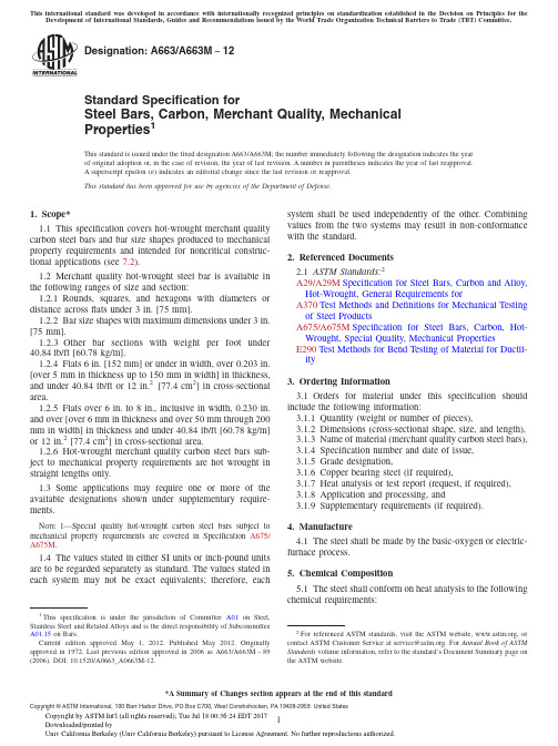
Designation:A663/A663M −12Standard Specification forSteel Bars,Carbon,Merchant Quality,Mechanical Properties 1This standard is issued under the fixed designation A663/A663M;the number immediately following the designation indicates the year of original adoption or,in the case of revision,the year of last revision.A number in parentheses indicates the year of last reapproval.A superscript epsilon (´)indicates an editorial change since the last revision or reapproval.This standard has been approved for use by agencies of the Department of Defense.1.Scope*1.1This specification covers hot-wrought merchant quality carbon steel bars and bar size shapes produced to mechanical property requirements and intended for noncritical construc-tional applications (see 7.2).1.2Merchant quality hot-wrought steel bar is available in the following ranges of size and section:1.2.1Rounds,squares,and hexagons with diameters or distance across flats under 3in.[75mm].1.2.2Bar size shapes with maximum dimensions under 3in.[75mm].1.2.3Other bar sections with weight per foot under 40.84lb/ft [60.78kg/m].1.2.4Flats 6in.[152mm]or under in width,over 0.203in.[over 5mm in thickness up to 150mm in width]in thickness,and under 40.84lb/ft or 12in.2[77.4cm 2]in cross-sectional area.1.2.5Flats over 6in.to 8in.,inclusive in width,0.230in.and over [over 6mm in thickness and over 50mm through 200mm in width]in thickness and under 40.84lb/ft [60.78kg/m]or 12in.2[77.4cm 2]in cross-sectional area.1.2.6Hot-wrought merchant quality carbon steel bars sub-ject to mechanical property requirements are hot wrought in straight lengths only.1.3Some applications may require one or more of the available designations shown under supplementary require-ments.N OTE 1—Special quality hot-wrought carbon steel bars subject to mechanical property requirements are covered in Specification A675/A675M .1.4The values stated in either SI units or inch-pound units are to be regarded separately as standard.The values stated in each system may not be exact equivalents;therefore,eachsystem shall be used independently of the bining values from the two systems may result in non-conformance with the standard.2.Referenced Documents2.1ASTM Standards:2A29/A29M Specification for Steel Bars,Carbon and Alloy,Hot-Wrought,General Requirements forA370Test Methods and Definitions for Mechanical Testing of Steel ProductsA675/A675M Specification for Steel Bars,Carbon,Hot-Wrought,Special Quality,Mechanical PropertiesE290Test Methods for Bend Testing of Material for Ductil-ity3.Ordering Information3.1Orders for material under this specification should include the following information:3.1.1Quantity (weight or number of pieces),3.1.2Dimensions (cross-sectional shape,size,and length),3.1.3Name of material (merchant quality carbon steel bars),3.1.4Specification number and date of issue,3.1.5Grade designation,3.1.6Copper bearing steel (if required),3.1.7Heat analysis or test report (request,if required),3.1.8Application and processing,and3.1.9Supplementary requirements (if required).4.Manufacture4.1The steel shall be made by the basic-oxygen or electric-furnace process.5.Chemical Composition5.1The steel shall conform on heat analysis to the following chemical requirements:1This specification is under the jurisdiction of Committee A01on Steel,Stainless Steel and Related Alloys and is the direct responsibility of Subcommittee A01.15on Bars.Current edition approved May 1,2012.Published May 2012.Originally approved in st previous edition approved in 2006as A663/A663M –89(2006).DOI:10.1520/A0663_A0663M-12.2For referenced ASTM standards,visit the ASTM website,,or contact ASTM Customer Service at service@.For Annual Book of ASTM Standards volume information,refer to the standard’s Document Summary page on the ASTM website.*A Summary of Changes section appears at the end of this standardCopyright ©ASTM International,100Barr Harbor Drive,PO Box C700,West Conshohocken,PA 19428-2959.United StatesThis international standard was developed in accordance with internationally recognized principles on standardization established in the Decision on Principles for theDevelopment of International Standards,Guides and Recommendations issued by the World Trade Organization Technical Barriers to Trade (TBT)Committee.Phosphorus,max,percent 0.04Sulfur,max,percent0.05Copper,when copper steel is specified,min,percent0.206.Mechanical Properties6.1Tensile Requirements:6.1.1The material as represented by the test specimen shall conform to the applicable requirements in Table 1.6.1.2Test specimens shall be prepared for testing from the material in its as-rolled condition.The tension specimen may be aged as described in Test Methods and Definitions A370.6.1.3Test specimens shall be taken longitudinally and may be tested in full thickness or section,or they may be machined to the dimensions shown in Figs.4or 5of Test Methods and Definitions A370.If test specimens are selected conforming to the dimensions of Fig.5,they shall be machined from a position midway between the center and the surface of the bar.6.1.4Test specimens for shapes and flats may be machined to the form and dimensions shown in Fig.4of Test Methods and Definitions A370or with both edges parallel.Test speci-mens for material over 11⁄2in.[40mm]in thickness or diameter may be machined to a thickness or diameter of at least 3⁄4in.[20mm]for a length of at least 9in.[230mm],or they may conform to the dimensions shown in Fig.5of Test Methods and Definitions A370.6.1.5Tensile requirements shall be determined in accor-dance with Test Methods and Definitions A370.6.1.6For material over 3⁄4in.[19mm]in thickness or diameter,a deduction from the percentage of elongation in 8in.[200mm]specified in Table 1of 0.25%shall be made for each increase of 1⁄32in.[0.8mm]in the specified thickness or diameter above 3⁄4in.[19mm].6.1.7For material under 5⁄16in.[8mm]in thickness or diameter,a deduction from the percentage of elongation in 8in.[200mm]specified in Table 1of 2.00%shall be made for eachdecrease of 1⁄32in.[0.8mm]in the specified thickness or diameter below 5⁄16in.[8mm].6.1.8For material over 2in.[50mm]in thickness or diameter,a deduction from the percentage of elongation in 2in.[50mm]specified in Table 1of 1.00%shall be made for each 1in.[25mm]of specified thickness or diameter or fraction thereof over 2in.[50mm]in thickness or diameter.6.2Number of Tests:6.2.1Two tension tests shall be made from each heat,unless the finished material from a heat is less than 50tons [45Mg],when one tension test will be sufficient.However,for material 2in.[50mm]and under in thickness,when the material from one heat differs 3⁄8in.[9.5mm]or more in thickness,one tension test shall be made from both the thickest and the thinnest material rolled,regardless of weight represented.For material over 2in.[50mm]thick,when the material from one heat differs 1in.[25mm]or more in thickness,one tension test shall be made from both the thickest and the thinnest material rolled that is more than 2in.[50mm]thick regardless of the weight represented.6.3Test Reports:6.3.1When test reports are required by the purchase order,the report shall show the results of each test required by 6.2,except that only one test need be reported when the amount of material from a heat in a shipment is less than 10tons [9Mg]and when the thickness variations described in 6.2are not exceeded.6.3.2The thickness of the product tested may not necessar-ily be the same as an individual ordered thickness since it is the heat that is tested rather than each ordered item.6.3.3When Supplementary Requirements are specified,the report shall include a statement of compliance with the requirement or the results of tests when the requirement involves measured test values.7.General Requirements7.1Material furnished under this specification shall con-form to the requirements of the current edition of Specification A29/A29M ,except as stated in 1.2and 3.2.7.2Merchant quality bars shall be free from visible pipe;however,they may contain pronounced chemical segregation.Internal porosity,surface seams,and other surface irregularities may be present in this quality.Deoxidation practice and grain size are at the manufacturer’s option.7.3Unless otherwise specified,the bars shall be furnished as rolled and not pickled,blast cleaned,or oiled.8.Keywords8.1carbon steel bars;merchant quality steel bars;steel barsTABLE 1Tensile RequirementsElongation,min,%Grade Designation Tensile Strength,ksi [MPa]Yield Point,Amin,ksi [MPa]8-in.or [200-mm]Gage Length2-in.or [50-mm]Gage Length45[310]45–55[310–380]25.0[175]273350[345]50–60[345–415]28.0[195]253055[380]55–65[380–450]30.0[210]232660[415]60–72[415–495]33.0[230]212265[450]65–77[450–530]36.0[250]172070[485]70–85[485–585]39.0[270]141875[515]75–90[515–620]41.0[285]141880[550]80min [550min]44.0[305]1317AWhen the tension test does not show a yield point (drop of the beam,halt of the pointer or sharp-kneed stress-strain diagram),yield strength shall be deter-mined by either 0.5%extension-under-load or 0.2%offset.The minimum ksi (MPa)requirement does not change.The test report,if required,shall show yieldstrength.SUPPLEMENTARY REQUIREMENTSOne or more of the following supplementary requirements shall apply when specified by the purchaser.S1.Special StraightnessS1.1Bars may be specified to special straightness tolerance (refer to Specification A29/A29M ).S2.CleaningS2.1The purchaser may specify that the surface of bars be descaled by pickling or blast cleaning.S3.CoatingS3.1The purchaser may specify oil on bars which have been descaled.S4.Bend TestsS4.1Requirements:S4.1.1The bend test specimen shall stand being bent at room temperature through 180°without cracking on the outside of the bent portion,to an inside diameter which shall have the relation to the thickness or diameter of the specimen as given in Table S4.1.S4.2Test Specimens:S4.2.1Bend test specimens for material 11⁄2in.[40mm]and under in diameter or thickness may be the full thickness of the section.For flat bars over 2in.[50mm]in width,the width may be reduced by milling to 11⁄2in.[40mm].S4.2.2Bend test specimens for material over 11⁄2in.[40mm]in diameter or thickness may be machined to a thickness or diameter of at least 3⁄4in.[20mm]or to 1in.by 1⁄2in.[25by 12.5mm]in section.Machined sides of bend test specimens may have the corners rounded to a radius of not over 1⁄16in.[1.6mm]for material 2in.[50mm]and under inthickness,and not over 1⁄8in.[3.2mm]in radius for material over 2in.[50mm]in thickness.S4.3Number of Tests:S4.3.1Two bend tests shall be made from each heat unless the finished material from a heat is less than 50tons [45Mg]when one bend test will be sufficient.However,for material 2in.[50mm]and under in thickness,when the material from one heat differs 3⁄8in.[9.5mm]or more in thickness,one bend test shall be made from the thickest and the thinnest material rolled,regardless of weight represented.For material over 2in.[50mm]thick,when the material from one heat differs 1in.[25mm]or more in thickness,one bend test shall be made from both the thickest and the thinnest material rolled that is more than 2in.[50mm]thick regardless of the weight represented.S4.4Test Methods:S4.4.1Bend tests shall be made in accordance with Test Methods E290.SUMMARY OF CHANGESCommittee A01has identified the location of selected changes to this standard since the last issue (A663/A663M –89(2006))that may impact the use of this standard.(Approved May 1,2012.)(1)Removed previous subsection 6.1.6.TABLE S4.1Bend RequirementsRatio of Bend Diameter to Thickness of Specimenfor Thickness or Diameter of Bar,in.(mm)Grade Designation 3⁄4[20]andUnder Over 3⁄4[20]to1[25],inclOver 1[25]to 11⁄2[40],inclOver 11⁄2[40]to 2[50],incl Over 2[50]to under 3[75]45[310]flat flat 1⁄21150[345]flat 1⁄2111⁄221⁄255[380]1⁄2111⁄2221⁄260[415]1⁄2111⁄221⁄2365[450]111⁄22331⁄270[485]11⁄2221⁄2331⁄275[515]22331⁄2480[550]221⁄2331⁄24ASTM International takes no position respecting the validity of any patent rights asserted in connection with any item mentioned in this ers of this standard are expressly advised that determination of the validity of any such patent rights,and the risk of infringement of such rights,are entirely their own responsibility.This standard is subject to revision at any time by the responsible technical committee and must be reviewed everyfive years and if not revised,either reapproved or withdrawn.Your comments are invited either for revision of this standard or for additional standards and should be addressed to ASTM International Headquarters.Your comments will receive careful consideration at a meeting of the responsible technical committee,which you may attend.If you feel that your comments have not received a fair hearing you should make your views known to the ASTM Committee on Standards,at the address shown below.This standard is copyrighted by ASTM International,100Barr Harbor Drive,PO Box C700,West Conshohocken,PA19428-2959, United States.Individual reprints(single or multiple copies)of this standard may be obtained by contacting ASTM at the above address or at610-832-9585(phone),610-832-9555(fax),or service@(e-mail);or through the ASTM website ().Permission rights to photocopy the standard may also be secured from the ASTM website(/ COPYRIGHT/).。
68crnimo3-3 标准
68crnimo3-3标准
"68CrNiMo3-3"通常是一种钢材牌号,这可能与DIN EN10083标准相关。
这个标准规定了热轧和锻造的钢材,包括合金钢,用于制造机械零件,例如轴承、齿轮、曲轴等。
具体而言,"68CrNiMo3-3"中的数字和字母代表了以下含义:
-68:钢中碳含量的近似百分比。
-Cr:合金元素铬(Chromium)。
-Ni:合金元素镍(Nickel)。
-Mo:合金元素钼(Molybdenum)。
-3:合金元素的数量或者其他特殊标记,可能表示特殊的处理条件或者特殊的合金配方。
具体的技术要求和化学成分会根据具体的标准而有所不同。
要获取准确的信息,建议查阅相应的DIN EN10083标准文件,该标准规定了这类合金钢的要求、检验和标志等。
请注意,具体的标准版本可能影响到相关的规范和要求。
IEC62133讲解
1.概述1.1范围本国际标准规定了便携式密封式二次电池包括碱性的或非酸性电解液电池芯和电池(不包含扣式电池)在正常使用和可能的误操作下的安全性要求和试验方法。
1.2引用标准下列标准化文件所包含的条文,通过在本国际标准的引用而构成本标准的条文,有时效规定的引用,引用标准在本标准颁布后的改编、修正版不在引用之列。
当然本国际标准制定委员会鼓励去探讨引用下列所示标准最新版本的可能性。
无时效的引用,最新版本的内容将被采用。
IEC和ISO委员将继续登记最新的有效的国际标准。
IEC 60285 碱性二次电池芯和电池——密封式镍镉圆柱型可充单个电池芯IEC 60664(全部章节)有低压系统的设备的绝缘配置IEC 61436二次电池芯和电池包括碱性或非酸性电解液电池——密封式镍氢可充单个电池芯IEC 61440二次电池包括碱性或非酸性电解液电池——密封式镍镉小棱形可充单个电池芯IEC 61809 二次电池包括碱性或非酸性电解液电池——便携式密封式碱性二次电池芯和电池安全要求IEC 61951-1二次电池包括碱性或非酸性电解液电池——便携式密封可充电电池芯第一部分:镍—镉电池IEC 61951-2二次电池包括碱性或非酸性电解液电池——便携式密封可充电电池芯第一部分:镍氢电池IEC 61960-1 and 61960-2便携式二次锂电池芯和电池1.二次锂电池芯2.二次锂电池1.3定义本国际标准采用的IEC60050-486和IEC/ISO导则5.1的术语和下列概念。
1.3.1安全性不会发生不可接受的危险1.3.2危险包括发生伤害的可能性和伤害的严重性1.3.3伤害包括人身伤害,对人类健康的危害,对财产的损害及对环境的破坏1.3.4隐患发生伤害的潜在的源由1.3.5正常使用产品的使用过程和服务完全按供应商所提供的规格和使用说明书和文件执行1.3.6可能发生的误操作产品使用不当,没按供应商的要求做,但可能是人类习惯行为导致的结果1.3.7二次电池芯厂家生产出来的电能和化学能转化的基本单元,包含电极、隔膜、电解液、电池壳、接线终端1.3.8二次电池二次电池芯的装配体:有它自己的电压、尺寸、终端设计、容量和额定功能1.3.9漏液目测可见的电解液液体的渗出1.3.10 泄放电池芯或电池内部过剩压力在设计的安全阀处释放造成的破裂或爆炸1.3.11破裂由于内部或外面的原因,电池芯的壳或电池壳发生机械破坏,导致爆炸或漏液1.3.12爆炸电池壳炸裂,主要元件猛然冲出来的现象1.3.13起火电池芯或电池喷射出火焰1.3.14便携式电池安装在手提式用具上的电池1.3.15便携式电池芯可以装配到便携式电池上的电池芯1.3.16额定容量生产厂标明的C5Ah (安时)容量,是指电池在规定条件下,充电、储存、放电后,在20℃以0.2I t A的参考试验电流放电到终止电压1.0V所释放的放电容量1.4 参数测量公差对于所有的规定的参数或实际参数的精度控制和测量值,都应满足下列公差:a)±1%——电压b)±1%——电流c)±2℃——温度d)±0.1%——时间e)±1%——尺寸f)±1%——容量这些公差包含系统误差和人为误差。
对称三硝基苯化学品安全技术说明书MSDS

中文名称:对称三硝基苯中文别名:1,3,5-三硝基苯(干的或含水<30%)英文名称:1,3,5-trinitrobenzene(dry orwetted with less than 30%water,by mass)英文别名:TNBCAS号:99-35-4技术说明书编码:MSDS#1第二部分:危险性概述危险性类别:第1类 爆炸品侵入途径:吸入 食入对称三硝基苯化学品安全技术说明书编码:MSDS#1编制日期:_____________然后收集回收或运至废物处理场所处置。
第七部分:操作处置与储存操作注意事项:密闭操作,提供充分的局部排风。
操作人员必须经过专门培训,严格遵守操作规程。
建议操作人员佩戴自吸过滤式防尘口罩,戴化学安全防护眼镜,穿紧袖工作服,长筒胶鞋,戴橡胶手套。
远离火种、热源,工作场所严禁吸烟。
使用防爆型的通风系统和设备。
避免产生粉尘。
避免与氧化剂、还原剂、活性金属粉末、碱类接触。
搬运时要轻装轻卸,防止包装及容器损坏。
禁止震动、撞击和摩擦。
配备相应品种和数量的消防器材及泄漏应急处理设备。
储存注意事项:储存于阴凉、干燥、通风的专用爆炸品库房。
远离火种、热源。
应与氧化剂、还原剂、活性金属粉末、碱类分开存放,切忌混储。
采用防爆型照明、通风设施。
禁止使用易产生火花的机械设备和工具。
储区应备有合适的材料收容泄漏物。
禁止震动、撞击和摩擦。
第八部分:接触控制/个体防护中国MAC(mg/m3):1[皮]前苏联MAC(mg/m3):未制定标准燃烧热(kJ/mol):2774.3临界压力(MPa):无资料爆炸上限%(V/V):无资料爆炸下限%(V/V):无资料外观与性状:白色或黄色斜方结晶。
主要用途:用于制造猛性炸药。
其它理化性质:无资料第十部分:稳定性和反应活性稳定性:稳定禁配物:强氧化剂、强还原剂、活性金属粉末、强碱。
避免接触的条件:受热。
聚合危害:不能出现分解产物:无资料IMDG规则页码:1104包装标志:1包装类别:O52包装方法:螺纹口玻璃瓶、铁盖压口玻璃瓶、塑料瓶或金属桶(罐)外普通木箱。
- 1、下载文档前请自行甄别文档内容的完整性,平台不提供额外的编辑、内容补充、找答案等附加服务。
- 2、"仅部分预览"的文档,不可在线预览部分如存在完整性等问题,可反馈申请退款(可完整预览的文档不适用该条件!)。
- 3、如文档侵犯您的权益,请联系客服反馈,我们会尽快为您处理(人工客服工作时间:9:00-18:30)。
66163-3 Product Details
Home | Customer Support | Suppliers | Site Map | Privacy Policy | Browser Support
© 2008 Tyco Electronics Corporation All Rights Reserved Search
Products Documentation Resources My Account Customer Support Home > Products > By Type > Product Feature Selector > Product Details
No Image Available
66163-3
Active Taper Pins and Blocks
Not reviewed for RoHS Compliance
Product Highlights:
?Taper Pins
?Pin Type = Solid
?Pin Style = Round Nose (NASA)
?53 Series
?Loose Piece
View all Features | Find Similar
Products
Check Pricing &
Availability
Search for Tooling
Product Feature
Selector
Contact Us About
This Product
Quick Links
Documentation & Additional Information
Product Drawings:
?pin taper 53 series non insulated support(PDF, English)
Catalog Pages/Data Sheets:
?None Available
Product Specifications:
?Contact, TAYP-AIR Pins and Blocks(PDF, English)
?Contact, Taper Pins(PDF, English)
Application Specifications:
?None Available
Instruction Sheets:
?None Available
CAD Files:
?None Available
List all Documents Additional Information:
?Product Line Information
Related Products:
?Tooling
Product Features (Please use the Product Drawing for all design activity)
Product Type Features:
?Product Type = Taper Pins
?Insulation Support = Non-Insulation Support ?Finish = Gold (30)
?Comment = For Stranded Wire Only.
Body Related Features:
?Pin Type = Solid
?Pin Style = Round Nose (NASA)
?Series = 53
?Wire Range (mm [AWG]) = 1.25-1.40²[16] ?Overall Length (mm [in]) = 19.81 [0.780]
?Mates With = 53 Series Connector Block Industry Standards:
?RoHS/ELV Compliance = Not reviewed for
ELV/RoHS compliance
?Lead Free Solder Processes = Not reviewed for
lead free solder process
Packaging Related Features:
?Packaging Method = Loose Piece
Other:
?Brand = AMP
Provide Website Feedback | Contact Customer Support。