B12P-SHF-1AA中文资料
HDD50-12S12P中文资料
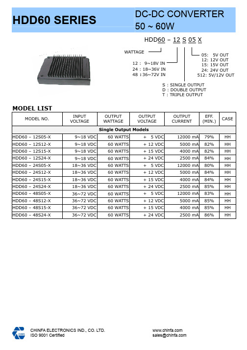
HDD60 – 12 S 05 XMODEL LISTMODEL NO.INPUT VOLTAGEOUTPUT WATTAGEOUTPUT VOLTAGEOUTPUT CURRENTEFF . (MIN.)CASESingle Output ModelsHDD60 – 12S05-X 9~18 VDC 60 WATTS + 5 VDC 12000 mA 79% HH HDD60 – 12S12-X 9~18 VDC 60 WATTS + 12 VDC 5000 mA 82% HH HDD60 – 12S15-X 9~18 VDC 60 WATTS + 15 VDC 4000 mA 82% HH HDD60 – 12S24-X 9~18 VDC 60 WATTS + 24 VDC 2500 mA 84% HH HDD60 – 24S05-X 18~36 VDC 60 WATTS + 5 VDC 12000 mA 80% HH HDD60 – 24S12-X 18~36 VDC 60 WATTS + 12 VDC 5000 mA 84% HH HDD60 – 24S15-X 18~36 VDC 60 WATTS + 15 VDC 4000 mA 84% HH HDD60 – 24S24-X 18~36 VDC 60 WATTS + 24 VDC 2500 mA 85% HH HDD60 – 48S05-X 36~72 VDC 60 WATTS + 5 VDC 12000 mA 83% HH HDD60 – 48S12-X 36~72 VDC 60 WATTS + 12 VDC 5000 mA 85% HH HDD60 – 48S15-X 36~72 VDC 60 WATTS + 15 VDC 4000 mA 85% HH HDD60 – 48S24-X36~72 VDC60 WATTS+ 24 VDC2500 mA86%HH12 : 9~18V IN 24 : 18~36V IN 48 :36~72V INS : SINGLE OUTPUT D : DOUBLE OUTPUTT : TRIPLE OUTPUT WATTAGE 05: 5V OUT 12: 12V OUT 15: 15V OUT 24: 24V OUT 512: 5V/12V OUTMODEL NO. INPUTVOLTAGEOUTPUTWATTAGEOUTPUTVOLTAGEOUTPUTCURRENTEFF.(MIN.) CASE Double Output ModelsHDD50 – 12D05-X 9~18 VDC50 WATTS5V / 5V5A / 5A78% HH HDD60 – 12D12-X 9~18 VDC60 WATTS12V / 12V 2.5A / 2.5A80% HH HDD60 – 12D15-X 9~18 VDC60 WATTS15V / 15V2A / 2A80% HH HDD60 – 12D512-X 9~18 VDC55 WATTS5V / 12V5A / 2.5A79% HH HDD50 – 24D05-X 18~36 VDC50 WATTS5V / 5V5A / 5A80% HH HDD60 – 24D12-X 18~36 VDC60 WATTS12V / 12V 2.5A / 2.5A82% HH HDD60 – 24D15-X 18~36 VDC60 WATTS15V / 15V2A / 2A82% HH HDD60 – 24D512-X 18~36 VDC60 WATTS5V / 12V6A / 2.5A80% HH HDD50 – 48D12-X 36~72 VDC50 WATTS5V / 5V5A / 5A80% HH HDD60 – 48D12-X 36~72 VDC60 WATTS12V / 12V 2.5A / 2.5A84% HH HDD60 – 48D15-X 36~72 VDC60 WATTS15V / 15V2A / 2A84% HH HDD60 – 48D512-X 36~72 VDC60 WATTS5V / 12V6A / 2.5A81% HHTriple Output ModelsHDD55 – 12T512-X 9~18 VDC55 WATTS+5V / ±12V+5A / ±1.25A78% HH HDD55 – 24T512-X 18~36 VDC55 WATTS+5V / ±12V+5A / ±1.25A79% HH HDD55 – 48T512-X 36~72 VDC55 WATTS+5V / ±12V+5A / ±1.25A80% HH--SUFFIX “X=P” : PCB MOUNTING TYPE, HEATSINK WILL BE ADDED ON MODULE.--SUFFIX “X=T” : CHASSIS MOUNTING TYPE:(TERMINAL BLOCK), NO HEATSINK. USE CHASSIS AS HEATSINK OR FAN FORCE COOLING. INDICATE SUFFIX WHEN ORDER.--SPECIFICATIONS SUBJECT TO CHANGE WITHOUT NOTICED.FEATURES* 50W to 60W DC/DC CONVERTER* 2:1 INPUT RANGE, PI INPUT FILTER* ISOLATION INPUT AND OUTPUT* HIGH PERFORMANCE UP TO 86%* SHORT CIRCUIT PROTECTION* 2 YEARS WARRANTYSPECIFICATIONAll Specifications Typical At Nominal Line, Full Load, 25 Unless Otherwise Noticed ℃GENERAL SPECIFICATION* Switching frequency: ......................... * Isolation voltage: .............................. * Isolation resistance: .......................... * Operating ambient temperature: ......... * Storage temperature: ........................ * Max. Case temperature: ..................... * M.T .B.F .: .......................................... * Cooling: ........................................... * Transient recovery time: .................... * Temperature coefficient: .................... * Dimension: ......................................>80KHz (typ.) 1,500VDC >1G Ω(min.) -25 to +71℃ -25 to +100℃ 95℃122,500Hrs at @ GF40, according to MIL-HDBK-217F Free air convection500µS, 25% load step change ±0.02% / ℃88.9 X 140 X 22.4mm INPUT SPECIFICATIONS* Input voltage range / frequency: ........ * Input filter: .......................................9 ~ 18VDC for 12V 18 ~ 36VDC for 24V 36 ~ 72VDC for 48V Pi type OUTPUT SPECIFICATIONS* Output voltage accuracy: ................... * Minimum load: ................................. * Line regulation: ................................ * Load regulation: ............................... * Ripple & noise: ................................. * Efficiency: ........................................ * Voltage trim range: ........................... * Derating: ......................................... * Case material: ..................................±1% at Vo_nomNo load for +5V , 20% for ±12V for triple ±1% at Vo_nom±2% at Vo_nom for single output models ±2% at Vo_nom for dual output models ±1% mV (max.)Up to 86%, see model list ±10% at Vo_nom See table 1 Metal CONTROL AND PROTECTION* Remote on/off: ................................. * Output short circuit: ..........................ON : Open or +5.5VDC(Min.) OFF : +1.8VDC(Max.) Continuous90-25Ambient Temperture [℃]7060100Powerout[%]MECHANISM & PIN CONFIGURATION PHYSICAL CHARACTERISTICSDerating: [TABLE 1]CASE SIZE 88.9 X 140 X 22.4mm5.5 x 3.5 x 0.88inchesCASE MATERIAL MetalWEIGHT 550g。
IXA12IF1200PB IGBT模块说明书

Copack
Part number
IXA12IF1200PB
IXA12IF1200PB
VCES =
I C25
=
V = CE(sat)
preliminary
1200 V 20 A 1.8 V
(G) 1
2 (C) 3 (E)
Backside: collector
Features / Advantages:
* on die level
IGBT
1.1 153
T VJ = 150 °C
Diode
1.25
V
85 mΩ
IXYS reserves the right to change limits, conditions and dimensions.
© 2011 IXYS all rights reserved
● Thin wafer technology combined with the XPT design results in a competitive low VCE(sat)
● SONIC™ diode - fast and soft reverse recovery - low operating forward voltage
IXA12IF1200PB
preliminary
Conditions
IC = 10A; VGE = 15 V IC = 0.3mA; VGE = VCE VCE = VCES; VGE = 0 V VGE = ±20 V VCE = 600 V; VGE = 15 V; IC =
inductive load VCE = 600 V; IC = 10 A VGE = ±15 V; RG=100 Ω
FORCE 12 Powered Mixer 操作手册和用户指南说明书
FORCE 12 Powered Mixer OPERATING MANUAL AND USER GUIDEFORCE 12Powered MixerTABLE OF CONTENTSTABLE OF CONTENTS (1)IMPORTANT WARNINGS & SAFETY INFORMATIONS (2)INTRODUCTION (3)ABOUT THE FORCE 12 (3)FORCE 12 FEATURES (3)CHANNEL CH1-6 (4)CHANNEL CH7-8 (5)CHANNEL CH9/10 (6)CHANNEL CH11/12 (7)FORCE 12 MASTER SECTION (8)FORCE 12 MASTER SECTION (9)FORCE 12 REAR PANEL (10)DIMENSIONS (11)USB INTERFACE (12)QUICK START GUIDE (12)WIRING DIAGRAMS (13)BLOCK DIAGRAM (14)SPECIFICATIONS (15)WHARFEDALE PRO LIMITED WARRANTY (16)1FORCE 12Powered Mixer INTRODUCTIONCongratulations on your purchase of the FORCE 12 portable powered mixer. The Wharfedale Pro FORCE 12is the result of many years of experience in the use, design and manufacture of professional audio equipment.We take great pride in engineering and building every Wharfedale Pro product and wish to thank you forentrusting us with your sound solutions.From the time Gilbert Briggs built his first loudspeaker in 1932, to the present day, Wharfedale have maintained the same standard of quality in components, workmanship and performance.Please take the time to read this manual completely in order to ensure that you get the most from your FORCE12 portable powered mixer.ABOUT THE FORCE 12Designed to be a perfect balance of portability and power the FORCE 12 is suitable for use in a wide rangeof portable sound applications. Everything you need to mix and amplify microphones and line level sources isincluded in one box, with an ergonomic carry handle to aid transportation.The one box concept speeds up your setup time and allows you to start your performance quicker than everbefore.All models feature built in digital FX processing, expanding your creativity and improving your sound qualitywithout the need for additional expensive and often cumbersome processors. A graphic EQ allows fine tuningof the overall mix.FORCE 12 FEATURES• 500W*2@4Ohms(RMS), 300W*2@8Ohms(RMS), 1300W*2@4Ohms(Peak)• 12 channels (8 mono & 2 stereo, play & record)• 10 Line inputs (6 Line, 2 Hi-z, 2 stereo)• 8 Mic inputs with switchable global +48V phantom power• Optional RCA&USB connections for 1 stereo channel• Parallel RCA& Line connections for 1 stereo channel• 3-band EQ control for each mono channel• 2-band EQ control for each stereo channel• Dual 7-band Graphic EQs with routing switch• 10 channel peak LED indicators and 1 Effects peak LED indicator• Dual 7-band Master Level LED indicators and 2 Limit LED indicators• Mute button for all the Mic channels• FX bypass button and FX Foot Switch to mute FX function• 56 sorts of stereo effects with LED digital display• Insert balanced/unbalanced 1/4” TRS jacks for the built-in stereo amplifiers• 5 low level outputs (Main L/R, Mon Send, FX Send, and Sub Out-80Hz LPF with 1/4” TRS jacks,and Record Output with RCA jacks)• Thermal protect, over current protect, DC protect, and output short protect• Speakon outputs for speakers• Light weight with 11kg31415-----Illuminates when the Effects clippingLED Digital Display -----56 sorts of stereo effects can be displayed via LED digital display -----Allows for master adjustment of the FX send bus.-----Selects the effect type.13579OPERATING MANUAL AND USER GUIDE12The USB connector enables computers with USB connectivity to interface directly with the FORCE 12 mixer for full duplex recording and playback. In recent years the introduction of USB connectivity has ushered a new appreciation of the capabilities of computer audio, helping to fuse both digital and analogue and open up endless possibilities for the recording musician.The internal AD (Analogue to Digital) and DA (Digital to Analogue) converters are 16-bit/48KHz enabling recording and playback above CD quality, ensuring that recordings that you make with a FORCE 12 have outstanding quality.The FORCE 12 is fully class compliant and requires no drivers when used with modern operating systems. Mac OSX, Windows XP, Vista and 7 will require no additional driver software.Windows XP InstallationSimply choose the device in the following location: Start/Settings/Control Panel/Sounds and Audio Devices/AudioMac OSX InstallationSimply select as an input and output device using the "Audio MIDI Setup" page, you can find this easily using the spotlight function.USB INTERFACEIn order to get up and running with your FORCE 12 follow the steps below:1.Zero the mixer. This involves setting all level and send controls to minimum and all EQ controls to 0dB.2.Make all connections for audio and power as per the wiring diagrams:• Ensure that the power switch is on the off position before connecting the AC supply.3.If your microphones require phantom power, use the rear panel switch to activate +48V supply.4.Turn the power switch on.5.Raise the level control for each of your connected sources, ensure that the Peak LED does not constantly illuminate.6.Raise the Mix Level control until you achieve the desired Sound Pressure Level (SPL).NOTEIf the sound becomes distorted at higher volumes you may need to add extra equipment to achieve the desired SPL, otherwise you may cause permanent damage to your system by overloading it. QUICK START GUIDEFORCE 12Powered Mixer15Model FORCE 12Power Output500W*2 RMS into 4 ohms(THD=1%@ 1KHz)550W*2 RMS into 4 ohms(THD=5%@ 1KHz)260W*2 RMS into 8 ohms(THD=1%@ 1KHz)290W*2 RMS into 8 ohms(THD=5%@ 1KHz)1300W*2 Peak into 4 ohms700W*2 Peak into 8 ohmsMaximum output levelMain L/R Mon Send +25dBu (14V) @THD=0.12%Sub Out(60Hz)+25dBu (14V) @THD=0.12%Fx Send +10dBu (2.5V) @THD=0.12%REC OUTPUT(Unbal out)+5dBu (1.4V) @THD=0.12%THD+NSpeakon out <0.13% @ 40Hz-20KHz 300W/4ohmMix/monitor out <0.005% @ 20Hz-30KHz MIC/LINE monoMix/monitor out <0.01% @ 20Hz-30KHz LINE stereoHum & NoiseSpeakon out -61dBu (All channel level 0dB, Main level 0dB)Mix/monitor out -87dBu (All channel level 0dB, Main level 0dB)MON-SEND out -95dBu (All channel level 0dB, Main level 0dB)Fx Send out -98dBu (All channel level 0dB, Main level 0dB)Frequency Response 20Hz-40kHz +1dB/-3dB (Mic/Line mono, Line stereo)Maximum voltage gain 97dB input mic to Speakon out67dB input mic to Mix/Mon47dB input mic to Rec out67dB input line to Speakon out59dB input tape/USB to speakon outInput channel equalisations High 12KHz shelvingMid 2KHz shelvingLow 100Hz shelvingMaximum: +/-15dB "Graphic equaliser Dual 7-band (60Hz, 120Hz, 480Hz, 1KHz, 4KHz,8KHz, 16KHz)Maximum: +/-12dB"Digital effects 56 EffectsROOM: r1 Closet; r2 Small ambient room;r3 Small bathroom; r4 Medium bathroom;r5 Large bathroom; r6 Small empty room;r7 Medium empty room ;r8 Large empty roomPLATE: P1 - P5HALL: h1 Medium hall 1; h2 Medium hall 2h3 Medium hall 3; h4 Large hall 1h5 Large hall 2; h6 Large hall 3h7 Church; h8 CathedralGATED REVERB: g1 - g3CHORUS: c1 - c4 Chorus 1-4c5 - c8 Chorus with reverb 1-4FLANGER: F1 - F6 Flanger 1-6F7 - F9 Flanger with reverb 1-2ROTARY SPEAKER: S1 - S7DELAY: D1 - D9Protection Power ON/OFF Mute; DC detection; Overload andshort detection; Temperature detectionPower AC100-120V~ 50/60Hz or AC220-240V~ 50/60Hz Product dimension(H*W*D)540*330*330mm (22*13*13 in)Net weight 11Kg (24lbs)SPECIFICATIONSWharfedale ProfessionalIAG House, 13/14 Glebe Road, Huntingdon, Cambridgeshire, PE29 7DL, UKWharfedale Professional reserves the right to alter or improve specifications without notice. All rights reserved © 2011 Wharfedale Pro. Wharfedale Pro is a member of the IAG Group.。
viper12

目前开关电源大量使用于各种电器设备中,且开关电源直接接在市电电网上,电源设备与电网之间有着双向的电磁干扰影响,对于较高频率的开关电源在设计中都需要考虑电磁兼容问题。
用VIPER12A芯片设计的开关电源具有节能特性,而且电磁兼容性较强,外围电路也很简单。
芯片VIPER12A简介芯片VIPER12A是意法半导体有限公司于2002年出的单片小功率开关电源。
具有固定60kHz的开关频率,芯片的电源电压范围很宽(9V-38V):具有电流控制型PWM调制器;具有滞后特性的欠压、过压、过流及过热保护功能等。
芯片外围电路很简单并具有节能特性。
由于VIPER12A内部的功率MOSFET管是一种特殊的“灵敏场效应管”如图1所示,有两个源极S1、S2,其中S1接外部参考地,S2用于电流检测,且IS1>>IS2,因此,能无损检测出漏极电流ID,从而达到节能。
而其他类型开关电源的漏极电流都是百分之百地通过检测电阻,这必然增加功耗,导致电源效率降低。
图2为系统整体框图,电网电源经过整流滤波后可得到峰值约为31OV的直流高压,同时还设有保护电路及抗电磁干扰电路,然后经过功率转化为+5V脉动直流电压,再经二次滤波后得到+5V恒压源。
为了适应不同电压和负载的变化,从输出回路取样反馈,通过开关集成器控制输入回路,从而得到+5V稳压输出。
本系统重点是电磁兼容(EMC)的设计。
电磁兼容(EMC)设计开关电源是较强的电磁干扰发射源。
这是因为开关电源的整流桥是非线性器件,其形成的电流是严重失真的正弦半波,含有丰富的高次谐波。
同时,功率开关管等半导体元件也会生产电磁干扰。
因此在设计中必须考虑电磁兼容性,主要抑制电磁干扰(EMI)和电磁脉冲(EMP)。
(1)抑制电磁干扰(EMI)电磁干扰(EMI)又叫噪声干扰,要抑制EMI关键是噪声滤波器的设计。
采用噪声滤波器能有效地抑制电网中的噪声进入设备,也可以抑制设备产生的噪声污染电网。
噪声有两种,一种是共模噪声,另一种是差模噪声。
Connector list(端子图表)
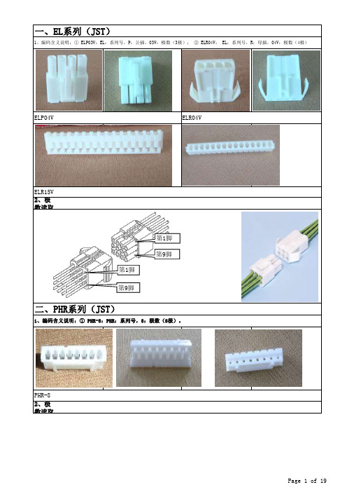
2、极数读取方法示意图:左图为母插,右图为公插(逆时针方向计数)。
2、极数读取方法示意图(逆时针方向计数)。
ELR04VELR15V二、PHR系列(JST)1、编码含义说明:① PHR-8:PHR:系列号,8:极数(8极)。
PHR-8一、EL系列(JST)1、编码含义说明:① ELP03V:EL:系列号,P:公插,03V:极数(3极); ② ELR04V: EL:系列号,R:母插,04V:极数(4极)ELP04V 第1脚第9脚第1脚第9脚第7脚第1 脚三、RA系列(JST)①类 1、编码含义说明:① RA-5011:RA:系列号,50:极数(50极),11:颜色(黑)。
RA50112、极数读取方法示意图。
第1脚第49脚②类 1、编码含义说明:① RA-H161TD-1190:RA:系列号,16:极数(16极),TD:直立型胶座,SD:侧边型胶座。
RA-H161TD-1190* RA-H161TD-1190使用于电路板中.按电路板实际要求使用即可.四、VL系列(JST)1、编码含义说明:① VLP02V:VL:系列号,P:公插,02V:极数(2极); ② VLR12V: VL:系列号,R:母插,12V:极数(12极)③ 个别特殊命名如: VLR-01VF,VLP-04V-1,其基本命名规则相同,只是结构尺寸不同。
VLP02V VLP04V-1VLR-12V VLR-01VF2、极数读取方法示意图。
第4第1第4第1五、XHP系列(JST)1、编码含义说明:① XHP-6:XHP:系列号,6:极数(6极)。
第5脚第1脚XHP-6极数判定示意图六、YL系列(JST)1、编码含义说明:① YLP12V:YL:系列号,P:公插,12V:极数(12极); ② YLR03V: YL:系列号,R:母插,03V:极数(3极)③ 个别特殊命名如: YLP-12VA,YLP-12VA,其基本命名规则相同,只是结构尺寸不同。
1 2英寸数字扭力适配器说明书

1/2"Drive Digital TorqueAdapterWhen unpacking your new digital torque adapter and related parts &accessories,please inspect it carefully for any damage that may haveoccurred during transit.If you have any questions,or require assistance with damaged or missing parts,please contact our factorycustomer servicedepartmentat:1-800-386-0191Pleasehavethe serialnumber,modelnumberand dateofpurchaseavailableforreferencewhencalling.This instruction manual is intended for your benefit.Please read and follow the safety,installation,maintenance and troubleshooting steps described within to ensure your safety and satisfaction.The contents of this instruction manual are based upon the latest product information available at the time of publication.Due to continuing improvements,actual product may differ slightly from the prod-uct described herein.Tools required for assembly and servicing are not included.INTRODUCTIONAfter opening the carton,unpack your new digital torque wrench adapter and related parts &acces-sories.Please inspect it carefully for any damage that may have occurred during transit.Please check it against the photograph on carton.If any parts are missing,please call factory customer ser-vice at 1-800-386-0191.UNPACKING &INSPECTIONDo not operate this tool if damaged during shipment,handling or misuse.Do not operate the tool until the parts have been replaced or the fault rectified.Failure to do so may result in serious per-sonal injury or property damage.All damaged parts must be repaired or replaced asneeded prior to operating this tool.Check to see that all nuts,bolts and fittings are secure before putting this tool into service.If you have any questions,or require assistance with damaged or missing parts,please contact our factory customer service department at:1-800-386-0191Please have the serial number,model number and date of purchase available for reference whencalling.WARNING -RISK OF FLYING PARTICLESREAD THIS MANUAL COMPLETELY BEFORE USING THE DIGITAL TORQUE ADAPTER•To insure accuracy,work must not move in angle mode.•For personal safety and to avoid wrench damage,follow good professional tool and fas-tener installation practices.•Periodic recalibration is necessary to maintain tool accuracy.USERS AND BYSTANDERS SHOULD ALWAYS WEAREYE PROTECTION•Besure all components,including adapters,extensions,drivers and sockets are rated to match or exceed the torque being applied with tool.•Observe all equipment,system and manufacturer’s warnings,cautions and procedures when using this adapter•Always use the correct size socket for the fastener being torqued.•Do not use damaged sockets,showing signs of wear or cracks.•Always replace damaged fasteners before applying torque.WARNING -Electrical Shock Hazard•Electrical shock can cause injury.•Plastic handle is not insulated.•Do not use on live electrical circuits.Over-torquing can cause breakage.An out of calibration torque wrench can cause part or tool breakage.Broken hand tools,sockets or accessories can cause injury.Excess force can cause crow foot or flare nut wrench slippage.IMPORTANT SAFEGUARDSIMPORTANT SAFEGUARDSto applying torque.•Never use this digital torque adapter to loosen fasteners as damage may occur.•Do not exceed the rated maximum torque value for the digital torque adapter as break-age and/or a loss of accuracy could occur.•Always verify the calibration of the digital torque adapter if you know or suspect its capac-ity has been exceeded.•Always pull-do not push-on the drive tool(ratchet)handle that is connected to the digi-tal torque adapter.•Adjust your stance to prevent a possible fall while applying torque.•Apply torque slowly and grasp the center of the handle.Do not apply load to the end ofthe handle.•Avoid applying excessive torque,turn the ratchet slowly and steadily as you apply torque.Pay attention to the LED light and sound indicators.•Never submerge the digital torque adapter in water or any other liquid.•If the tool gets wet,immediately wipe it dry with a soft,clean towel.•Do not expose this wrench to dust or sand as this could cause serious damage.•Use the digital torque adapter only for its intended purpose as described in this manual.•Do not use the digital torque adapter if it is not working properly or if it has suffered anydamage.•Do not disassemble the digital torque adapter.•Do not expose the digital torque adapter to extreme temperatures,humidity,direct sun-light.•Do not shake violently or drop digital torque adapter.•Do not use this tool as a hammer.•Position batteries in proper polarity.•Do not mix batteries of different type.•Never clean the digital torque adapter with soap or solvents.•Use a soft,dry,clean cloth to clean the digital torque adapter and LCD panel.•Do not apply excessive force to the LCD display panel.•Store in a clean dry place.•Keep this tool away from magnets.PRODUCT SPECIFICATIONSDrive size:1/2inchAccuracy:CW:±1%CCW:±2%Memory presets:10Display resolution:0.1NmOperation mode:Peak/TraceUnit selection:kg-cm,kg-m,lb-in,lb-ft,N-mBattery:(1)DC3V,CR2032Ambient temperature range:Operating:-10°C–60°C(13.9°F–139.9°F)Storage:-20°C-70°C(-4°F–157.9°F)Auto shut-off:80secondsTorque range:30-150Ft-lbs(41-203N-m)PRODUCT FEATURES•Digital torque readout.•Selectable for five torque units of measure:lb-ft,lb-in,kg-cm,kg-m and N-m.•+/-1%CW and +/-2%accuracy•Clockwise (CC)and counterclockwise (CCW)operation indicated on display.•Peak torque hold mode and Tracking torque mode selectable.•White LED backlight for easy reading.•Reverisble LCD display viewing orientation.•Multiple preset torque value indicators:audible buzzer,vibration alarm,red LED warning light.•Displays percentage of preset torque value attained.•Power saving automatic sleep mode activates after 3minues of inactivity.•Uses one (1)DC 3V,CR2032battery.•Batteries,storage case and calibration adapter included.displaybacklight barMain keyboardCONTROLSThe Titan Digital Torque Adapter displays fastener torque specification settings,torque readings and peak hold measurements.Mode key Warning buzzerpreset torque battery icon value of measure LCD DISPLAY INDICATORSWhen battery voltage drops below 2.6volts,a low battery warning icon willappear on the LCD display.When the battery voltage drops below 2.4volts,the low battery warning icon will begin to flash,indicating that immediate battery replacement isrequired.LOW BATTERY VOLTAGE INDICATIONBattery voltage under 2.4V POWERING ON DIGITAL TORQUE ADAPTERPress Mode button to turn digital torque adapter on and activate auto-zeroing process.Auto-zeroing processNormal mode(Preset number 0shown)CAUTION:Make sure the displayed applied torque value is zero during the auto-zeroing period.Otherwise a torque offset will be included.Select 1of 10user programable memory presets.SELECTING MEMORY PRESETSSETTING PRESET VALUES4.Five different unit selections are available:kg-cm,k-gm,in-lb,ft-lb,and N-m.SELECTING UNITS OF MEASURENOTE:When you change units,any target torque setting you have already entered will now be displayed in the new unit value.SELECTING PEAK HOLD/TRACKING MODESPressIn Track mode -The display will register “real-time”torque as it is applied.This is useful when you are able to observe the digital display while applying torque to a fastener.Watching the torque value increase can assist you in applying torque evenly and safely,especially as you approach your target torque setting.FullyreleaseDisplay retains peak torque achieved.PEAK HOLD MODE OPERATIONPeak Hold ModePercent of Target torqueApplytorque activatesRelease torque to zero-out torquereading and then apply torque again.Select pre-setting:200kg-cm(in this example)Applytorque and hold2sec.Toggle screen from Auto mode to Manual mode.Continue applying torque until preset torque value In Peak hold mode,the digital display shows the maximum torque applied,which can be helpful for verifying that the correct torque was applied when the digital display is not visible during use.This mode is also handy when using the adapter to calibrate a torque wrench.TRACKING MODE OPERATIONTracking ModeAt50%of Target torque:•Percentage of preset torque value is displayed•Buzzer sounds:Bi---Bi---Bi---•Select pre-setting:200kg-cmApply torque to reach preset torque value(200kg-cm in this example)At70%of target torque:At90%of target torque:At100%of target torque:•Percentage of preset torque value is displayed•Buzzer sounds:Bi-Bi-Bi-Bi•Red LED flashes:alert•Percentage of preset torque value is displayed•Buzzer sounds:BiBiBiBiBiBiBi•Percentage of preset torque value is displayedApplytorqueApplytorqueApplytorqueIn Tracking mode,the display will register torque as it is applied in real-time.This allows you to observe the digital display while applying torque to a fastener.Watching the torque value increase can assist you in applying torque evenly and safely,especially as you approach your target torque setting.Press and hold Mode button for 2seconds to turn unit off.NOTE:This tool will automatically enter sleep mode after 3minutes of inactivity.BATTERY INSTALLATION AND REPLACEMENT POWERING OFF DIGITAL TORQUEADAPTERPress and for 2seconds to toggle the orientation of the display readout.CHANGING ORIENTATION OFDISPLAYPress1.Requires one (1)DC 3V,CR2032.2.Unscrew battery cover fastener with a jewelers’phillips screwdriver.3.Remove the battery cover.4.Remove the old battery.5.Clean battery terminals.6.Install fresh battery in the digital torque adapter (with the “+”sign end facing upward).7.Replace the battery cover and screw tight.Note•Remove battery if stored for a long period of time.•Oil,water,dirt and sweat can prevent a battery’s terminals from making electrical contact.Wipe both terminals before installing batteries.Battery disposalOnly dispose of battery when fully discharged.DO NOT dispose of battery in a fire.Dispose of expended batteries andpackagingmaterialsinan environmentallyresponsiblemanner.1.Set your torque wrench to a value of approxi-mately 25%of its maximum capacity.Forexample,if your torque wrench has a maximumcapacity of 150lb-ft,set it to 40lb-ft.2.Program the digital torque adapter for a torquevalue that matches the torque wrench setting.In our example,you would set the adapter for40lb-ft.Ensure the adapter is in the “peak”mode as this will make it easy to referenceactual torque versus the torque indicated onthe wrench.3.Connect the pre-set torque wrench and theincluded calibration adapter to the digital torqueadapter.Secure the calibration adapter in abench vise.Ensure the calibration adapter issecurely tightened in the vise.4.Turn the torque wrench smoothly and steadily,applying torque to the calibration adapter untilyour torque wrench reaches the preset value,either by “clicking”(micrometer style torquewrench),or displaying the desired setting(digital or dial torque wrench).5.Read the peak torque value shown on the digi-tal torque adapter.Adjust your torque wrenchand repeat the procedure until the trquewrench and digital torque adapter show identi-cal torque values.DisposalDo not dispose of this device in normal domestic waste.Observe the currently valid regulations.In case of doubt,consult your waste disposal facility.CALIBRATING A TORQUE WRENCH USING DIGITAL ADAPTERIMPORTANT -Service,repair and calibration are to be performed by Star-Asia USA,LLC only.Cali-bration by the user is recorded in the wrench and voids factory certification.Contact Star-Asia USA,LLC for information on calibration service.PLEASENOTEUSER QUICK REFERENCE GUIDEMeasure Torque Presetting Target Torque90DAY LIMITED WARRANTY-STAR ASIA-USA,LLC POWER TOOLSStar Asia-USA,LLC(hereinafter“seller”)warrants to the original purchaser only,that this product will be free from defects in material or workmanship for a period of one year from date of purchase for home domestic use. Warranty PerformanceWarranty coverage is conditioned upon purchaser furnishing seller or its authorized service center with adequate written proof of the original purchase date.Products returned,freight prepaid and insured,to our factory or to an Authorized Service Center will be inspected and repaired or replaced,at seller‘s option,free of charge if found to be defective and subject to warranty.Defective parts not subject to normal wear and tear will be repaired or replaced,at our option during the above stated warranty periods.In any event,reimbursement is limited to the pur-chase price paid.Other than the postage and insurance requirement,no charge will be made for repairs or replacements covered by this warranty.Under no circumstances shall the manufacturer bear any responsibility for loss of the unit,loss of time or rental,inconvenience,commercial loss or consequential damages.There are no warranties which extend beyond the description of the face hereof.ExclusionsThis warranty does not cover parts damaged due to normal wear,abnormal conditions,misapplication,misuse, abuse,accidents,operation at other than recommended pressures or temperatures,improper storage or freight damage.Parts damaged or worn by operation in dusty environments are not warranted.Failure to follow recom-mended operating and maintenance procedures also voids warranty.Additional items not covered under this warranty:product failure caused by rain,excessive humidity,corrosive environments or other contaminants;cosmetic defects that do not interfere with product‘s functionality.This warranty shall not apply when:the product has been used for commercial or rental purposes;defects in mate-rials or workmanship or damages result from repairs or alterations which have been made or attempted by others or the unauthorized use of nonconforming parts;this damage is due to abuse,improper maintenance,neglect or accident;or the damage is due to use of the product after partial failure or use with improper accessories.Warran-ty does not apply to accessory items such as batteries.Seller will not be liable for:labor charges,loss or damage resulting from improper operation,maintenance or repairs made by persons other than a Star Asia-USA,LLC Authorized Service Center.The use of other than genuine Star Asia-USA,LLC Repair Parts will void warranty.Warranty DisclaimersNO WARRANTY,ORAL OR WRITTEN,OTHER THAN THE ABOVE WARRANTY IS MADE WITH REGARD TO THIS PRODUCT,ANY IMPLIED WARRANTIES OF SELLER REGARDING THIS PRODUCT INCLUDING BUT NOT LIMITED TO,THE IMPLIED WARRANTIES OF MERCHANTABILITY OR FITNESS FOR A PARTICULAR PURPOSE,ARE EXCLUDED.BUYER‘S OR USER‘S REMEDIES ARE SOLELY AND EXCLUSIVELY AS STATED ABOVE.STAR ASIA-USA,LLC SHALL IN NO EVENT BE LIABLE FOR INCIDENTAL,CONSEQUENTIAL,INDI-RECT,OR SPECIAL DAMAGES.IN NO EVENT,WHETHER AS A RESULT OF A BREACH OF CONTRACT, WARRANTY,TORT(INCLUDING NEGLIGENCE)OR OTHERWISE,SHALL SELLER‘S LIABILITY EXCEED THE PRICE OF THE PRODUCT WHICH HAS GIVEN RISE TO THE CLAIM OR LIABILITY.ANY LIABILITY CON-NECTED WITH THE USE OF THIS PRODUCT SHALL TERMINATE UPON THE EXPIRATION OF THE WAR-RANTY PERIODS SPECIFIED ABOVE.Limitations on Warranty DisclaimersAny implied warranties shall be limited in duration to one year from the date of purchase.In some states of the U.S.A.and in some provinces of Canada there is no limitation for how long an implied warranty is valid,so the aforementioned limitation may not apply to you.Star Asia-USA,LLC(hereinafter“seller”)warrants to the original purchaser only,that this product will be free from defects in material or workmanship for a period of one year from date of purchase for home domestic use. Distributed by Star Asia-USA,LLCP.O.Box58399,Renton,WA98058Consumer Service:800-386-0191e-mail:*****************©2013Star Asia-USA,LLC。
12V4A 电源适配器 2010-12-03承认书

变更履历表 ......................................................................................................................................................................3 1. 导言 Introducti.o..n...................................................................................................................................................4
1.1 电源概况 Power Supply Overvi..e..w.................................................................................................................4 1.2 描述 Descriptio..n..............................................................................................................................................4 2. 电气规格 Electrical Specifi.c..a..t..i..o..n......................................................................................4 2.1
海利普变频器A、M、F、H说明书中文版

● 在变频器输入前端接入接触器,控制变频器的起动或停止会影响 变频器的寿命,一般要求 通过 F OR或R E V端子来控制,在起、停 较为频繁场所,应特别注意使用。
● 变频器电源,请使用独立电源,绝对避免与电焊机等强干扰设备 共用同一电源,否则会引起变频器保护或变频器损坏。
2、送电中
危险
● 送电中绝不可插拔变频器上的连接器(CONNECTOR)以避免控 制主板因插拔所产生突波进入,造成变频器损坏。
HLPA009023B 单三相220V 50Hz 90 137.2
HLPA0D7543C 3Φ380V 50Hz 0.75 2.2
HLPA01D543C 3Φ380V 50Hz 1.5 3.2
HLPA02D243C 3Φ380V 50Hz 2.2 4.0
HLPA03D743B 3Φ380V 50Hz 3.7 6.8
功率 (KW)
驱动器 容量 (KVA)
18.5 32
输出 电流 (A)
40
22 37
47
30
52
65
37 64 80
4பைடு நூலகம் 72
91
55 84 110
75 116 152
90 134 176
110 160 210
132 193 253
160 230 304
185 260 340
200 290 380
220 325 426
HLPA0D7523C 单三相220V 50Hz 0.75 2.0
HLPA01D523C 单三相220V 50Hz 1.5 2.8
HLPA02D223B 单三相220V 50Hz 2.2 4.4
HLPA03D723B 单三相220V 50Hz 3.7 6.8
伺服驱动器12A8中文资料说明书

-
外部的
-
电流模式、IR 补偿模式、测速发电机模式、电压模式
-
有刷直流电机、音圈
-
过流、过温、过压、短路(相间和相地)
机械规格
单位
值
mm(in) 129.3×75.8×2280(9.9)
℃(℉) ℃(℉)
-
0-65 (32-149) -40-85(-40-185) 独立式
路、过压和过温,关掉所有功率开关器件并输出高电平。
无连接(保留)
-
无连接(保留)
-
引脚 1 2 3 4 5
名称 -MOT +MOT POWER GND POWER GND HIGH VOLTAGE
负电机输出 正电机输出
功率接口 P2 描述/注意点
功率地(与信号地相连)
直流电源输入
I/O O O GND GND I
限制电流的最大值,但不影响最大峰值限制电流值。
TTL 电平(+5V)禁止或使能输入。悬空时使能驱动器,接地时禁止驱动器。 I
JST连接器库存清单--精电连接

PCS PCS PCS PCS PCS PCS PCS PCS PCS PCS PCS PCS PCS PCS PCS PCS PCS PCS PCS PCS PCS PCS PCS PCS PCS PCS PCS PCS PCS PCS PCS PCS PCS PCS PCS PCS PCS PCS PCS PCS PCS PCS PCS PCS
85 86 87 88 89 90 91 92 93 94 95 96 97 98 99 100 101 102 103 104 105 106 107 108 109 110 111 112 113 114 115 116 117 118 119 120 121 122 123 124 125 126 127 128
VHR-8N XHP-10 XHP-2 XHP-3 XHP-4 XHP-6 XHP-8 XHP-9 YLR-02V ZHR-5 SLV04-30HGA A2006H00-2*15P-HK A2502H02-6P A1001HS0-30P-46 BHSMR-02VS SHR-04V-S-B SHR-13V-S-B SHDR-20V-S-B 10SSR-32H GHR 02V-S GHR-12V-S 16SUR-32S 22SUR-32S BM04B-ACHKS-A-GAN-TF BM40B-SHLDS-G-TFT SHLP-06V-BKHF-B SHLDP-30V-S-1(B) DCC20-30SA SSL20-30SB-1 USL20-40 SA SHR-10V-S-B SHDR-20V-S-B 04SUR-32S 12XSR-36S XHP-3 XHP-6 EHR-3 ZHR-2 ZHR-5 BHR-03VS-1 BHR-04VS-1 PHR-2 PHR-3 PHR-4
十二面体扬声器套件用户手册说明书

十二面体扬声器套件由十二面体声源 DS3 和 PA3 功放组成,它能发出声学频谱平坦的声学信号。
注意 进行此类声学测试时一定要佩戴听力保护装置。
标准操作流程1. 用附带的 Speakon 缆线连接 PA3 和十二面体扬声器;2. 接通 PA3 电源并打开开关 => “信号开(Signal ON)”按钮发出红光 (功放静音);3. 将遥控器天线与 PA3 连接;4. 按“信号源(Signal Source)”按钮选择所需的测试信号 => 被选中的信号源 LED 指示灯显示绿色 ;5. 按下“信号开(Signal ON)”按钮,或者遥控器按钮以实现 PA3 的发声 / 静音 => “信号开(Signal ON)”按钮显示绿色 (发声) /红色 (静音);6. 通过“音量调节(Level)”控制声源音量。
信号选择• EQ Pink 内置的经均衡的粉噪声信号,声源发出声学平坦的声音(见第三页,注脚 3)• EQ Line 为外部输入(Line IN)的信号应用内置均衡• Preset 3 内置的未均衡的粉噪声(用于最大化输出功率)• Preset 4 仅放大外部输入的信号,不应用均衡• Preset 5 预留(用于客户定制需求)外部输入(Line IN)使用 XLR 缆线将外部信号发生器与 PA3 功放连接,并 选择信号源为“EQ Line”或“Preset 4”低音炮操作流程用 XLR 缆线将 PA3 功放和有源低音炮连接,按下“启用低音炮(Subwoofer ON)”按钮 => “启用低音炮(Subwoofer ON)”按钮显示绿色功率放大器 PA3十二面体扬声器套件全指向性声源和功放PA3 遥控器十二面体扬声器 DS3LED 提示,除错电源开关电源接口十二面体扬声器输出接口外部信号发生器接口PA3 前面板PA3 技术指标最大短时输出功率 2 x 260 W 输入至 2x 4 Ω (@ 1 % THD)最大持续输出功率1) 2 x 150 W 输入至 2x 4 Ω (内置粉噪声 @ 最大声压级)负载电阻≥ 3 Ω(四脚连接)或 ≥ 8 Ω(两脚连接 / 桥接模式)保护动态压缩,温度,过流,直流,过载截断输出接口4-脚 Speakon(通道 1:1+/1– | 通道 2:2+/2– 或桥接模式:1+/2– )THD典型 0.017 % @ 2 x 120 W 输入至 2 x 4 Ω,1 kHz电平平坦度+0 / –3.3 dB2) @ 20 Hz 至 20 kHz信噪比≥ 86 dB,带宽 22 kHz阻尼因子≥ 120 @ 负载 ≥ 3 Ω 且频率 < 2 kHz电压增益静音 | 音量控制从 –18 dB 至 29.0 dB输入接口电平灵敏度最大输入电平阻抗XLR 平衡0 dBu 特定输出功率输入至 2 x 3 Ω / 2 x 4 Ω(最大增益)20 dBu / ±11 Vp10 kW 平衡低音输出接口增益最大输出电平阻抗截止滤波器XLR 平衡3 dB18 dBu / ±8.72 Vp≤ 600 Ω 平衡120 Hz 巴特沃斯低通滤波器,24 dB/倍频(四阶);辅助高通滤波器在低音炮激活时自动打开信号(可选)EQ Pink3) EQ Line Preset 3 Preset 4 Preset 5内置信号发生器,经均衡的粉噪声(Cf = 3.05)外部信号,经均衡内置信号发生器,未均衡的粉噪声(Cf = 3.4)外部信号,未均衡预留(视客户需求)十二面体声源 DS3 均衡1/3 倍频程1/1 倍频程100 Hz 至 8 kHz 平坦的声学响应100 dB re 1 pW ±3 dB 105 dB re 1 pW ±3 dBLED 提示截断(Clip)保护(Protect)外部输入信号在高温,过流等情况下功放自动关闭输出,具备自动重试功能控制信号开(Signal ON)音量(Level)信号源(Signal Source)启用低音炮(Subwoofer ON)开关信号并带有绿色 / 红色指示灯增益控制选择输出信号开关输出并带有绿色指示灯遥控功放输出开关认证• 欧洲:EMC 2014/30/EU,EN 61326-1:2013,EN 61000-3/4-x,EN 55011+A1:2009,R&TTE 标准 1999/5/EG• 中国:符合无线电管理要求• 日本:ARIB STD-T 67• 美国:FCC.15重量 5 kg (11 lbs)尺寸(长x宽x高)358 x 173 x 245 mm(14.1” x 6.8” x 9.7”)电源100 至 240 VAC,50/60 Hz,850 W保险丝T6.3 A(5 x 20 mm)温度和湿度范围0° 至 +50°C(32° 至 122°F)@ ≤ 90% RH(非冷凝),风扇主动降温配件(自带)• 无线遥控器• 便携包订购信息600 000 506(433 MHz) / 600 000 510(315 MHz,美国)/ 600 000 511(426 MHz,日本)1): 无滤波2): 非均衡,20 kHz 巴特沃斯高通滤波器(24 dB 阻尼因子)3): 非均衡,20 kHz 巴特沃斯高通滤波器(24 dB 阻尼因子)ISO16283-1:2014 标准对连续 1/3 倍频程段间的最小声压级能量差有要求。
MAA50-2K121212SBP中文资料
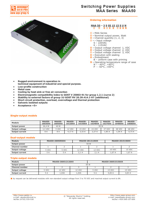
Single-output modelsModule МАА50- 1S03S ХХ МАА50- 1S05S ХХ МАА50- 1S12S ХХ МАА50- 1S15S ХХ МАА50- 1S24S ХХ МАА50- 1S27S ХХМАА50- 1S48S ХХ МАА50- 1S68S ХХ Output power 26,4 W 40 W 50 W Output voltage 3,3 VDC 5 VDC12 VDC15 VDC24 VDC27 VDC48 VDC68 VDCOutput current8 A8 А 4,17 А 3,33 А 2,27 А 1,85 А 1,04 А 0,73 АDual-output modelsModule МАА50-2S0505S ХХ МАА50-2S1212S ХХМАА50-2S1515S ХХOutput power 50 WChannel number 1 2 1 2 1 2 Output voltage 5 VDC 5 VDC 12 VDC 12 VDC15 VDC 15 VDC Output current5 А 5 А 2,1 А 2,1 А 1,67 А 1,67 АTriple-output modelsModule МАА50-3S051212S ХХМАА50-3S051515S ХХOutput power 50 WChannel number 1 2 3 1 2 3Output voltage 5 VDC12 VDC12 VDC5 VDC15 VDC15 VDCOutput current5 А 1,04А 1,04А 5 А 0,83 А 0,83 Аby request can be delivered modules with non-standard output voltage from 3 to 70 VDC and maximal output current to 8А.Ordering informationМАА 50 – 3 S 05 15 15 S U Nc d e f g h i j k lc - MAA Seriesd - Nominal output power, Watte - Channel quantity (1, 2, 3)f - - Input voltageS – 220VAC K – 115VACg - Output voltage channel 1, VDC h - Output voltage channel 2, VDC i - Output voltage channel 3, VDC j - Execution with sealing k - EmbodimentB – uniform case with primingl - Operating temperature range of caseN - - 40°С…+85°С P - - 50°С…+85°С• Rugged environment in operation intechnical equipment of industrial and special purpose. • Low-profile construction • Metal case• Cooling by heat sink or free air convection• Electromagnetic compatibility index to GOST V 25803-91 for group 1.2.1 (curve 2) • Stability to external factors of group 1U GOST RV 20.39.414.1-97 (additional) • Short circuit protection, overload, overvoltage and thermal protection • Galvanic isolated outputs •Acceptance «5»Температура окружающей среды Токр, С9080706050403020100-10-20-30-40-50Выходная мощность, Вт6050403020100Input specificationsParameter Conditions of dimensions MIN NOM MAX UnitS 187 220 242 VACSteady-state deviationК 80 115 140 VAC S 176 264 VACInput voltageTransient deflection, 1 secК 80 150 VAC SInput frequencyК47 400 440 HzOutput specificationsParameterConditions of dimensions MIN NOM MAX Unit Single-output execution (Inom 10 – 100%) ±3 % Output 1 multi-output execution(Inom 10 – 100%) ±3 %Uout2&3 differs from Uout1 less than 20% Output 2 and 3 multi-output execution(Inom 10 – 100%)±13 %Output 1 multi-output execution (Inom 30 – 100%) ±3 %Total output voltage instabilityUout2&3differs fromUout1 more than 20% Output 2 and 3 multi-output execution(Inom 50-100%) ±15 %Output voltage pulsations ripple(peak-to-peak)Dimension by device for pulsation control2% Uout.nom.Current overload protection actuation level110 % Iout.nom. Short circuit protection Autorepair 150 % Iout.nom. Overvoltage protection 120 % Uout.nom.Thermal protection90-95°CGeneral specificationsParameterConditions of dimensions MIN NOM MAX Unit- operating of case N P – 40 – 50 +85+85°C– power loss See diagram Temperature– storage – 50 +85 °CEfficiency 78 % Conversion frequency 50 kHz~ in/out 1500 VAC ~ in/case 1500 VAC~ out/case 500 VDC Isolation~ out/out 500 VDCInsulation resistance Voltage 500VDC 20 Ohm High humidity Temperature 35°С 98 % Cyclic overpatching of temperature – 60 +85 °C Multiple mechanical shocks Speeding-up 15g 2 15 ms Sinusoidal vibration Speeding-up 5g 50 500 Hz Atmosphere pressure 6х104 1,2х105 Pa Time to failure Temperature 35°C 105 hour Mass 0,4 kg all specifications redused for normal climatic conditions, Uin.nom., Iout.nom., if it is not specified differently.Power loss diagramFree airconvectionWith heat sinkAmbient temperature Tamb, °CO u t p u t p o w e r , WOutput settings№ pin1 2 3 4 5 6 7 8 9 Single-channel case ~IN (N) ~IN (L) +out1 +out1 +out1 -out1 -out1 -out1 Dual-channel case ~IN (N) ~IN (L) +out1 +out1 -out1 -out1 -out2 +out2 Triple-channelcase~IN (N)~IN (L)-out3+out3+out1-out1-out2+out2Switching on standart diagramFU in – current safety device 1A for input voltage 220VAC, 2A for input voltage 115VAC.S out – ceramic condenser capacity 0,47-15 mcF with corresponding operating voltage to decrease high-frequency noise level.S out2 – electronic condenser capacity 22-100 mcF in consideration with operating voltage and polarity. It makes for purpose to decrease dynamic instability when module work at dynamic load.+Out -Out ~In (L) ~In (N) Power module R heat CaseСout1 Сout2~In (L)~In (N)ground FU inSingle, Dual, and Triple-output execution SBNSingle, Dual, and Triple-output execution SVN (with flexible erection joints)The Flexible erection fjoints by length (100±5)mm is executed by wire section (0,5...1,5)mm2.。
PA12A中文资料

TC = –55 to +125°C, F > 60Hz TC = –55 to +125°C TC = –55 to +125°C Meets full range specification
PA12 MIN TYP
±VS –5 74
EQUIVALENT SCHEMATIC
3 D1
Q2A Q2B
4 A1
5 C1
6
Q1
2
Q3
1
7 Q4 Q5
8
Q6B Q6A
POWER RATING
Not all vendors use the same method to rate the power handling capability of a Power Op Amp. APEX rates the internal dissipation, which is consistent with rating methods used by transistor manufacturers and gives conservative results. Rating delivered power is highly application dependent and therefore can be misleading. For example, the 125W internal dissipation rating of the PA12 could be expressed as an output rating of 250W for audio (sine wave) or as 440W if using a single ended DC load. Please note that all vendors rate maximum power using an infinite heatsink.
JE12A6HTF1资料

*549}*9 +}9}
BfekXZk XiiXe^\d\ek TfckX^\ [ifg BfekXZk dXk\i`Xc BfekXZk iXk`e^ .P\j2 cfX[/ KXo2 jn`kZ_`e^ mfckX^\ KXo2 jn`kZ_`e^ Zlii\ek KXo2 jn`kZ_`e^ gfn\i K\Z_Xe`ZXc \e[liXeZ\ Dc\Zki`ZXc \e[liXeZ\ 5@ Rpg2> 94dT .Xk 54@/ KXo2> 694dT .Xk 54@/ Q`cm\i Xccfp 564@ 6;;T@B36<TCB 884T@B 564@ 77684T@377:4U 6 o 54 5 o 54
T`YiXk`fe i\j`jkXeZ\ Gld`[`kp @dY`\ek k\dg\iXkli\ R\id`eXk`fe Se`k n\`^_k BfejkilZk`fe
GMLFE@ PDJ@W HQM=445QHQM3RQ5:=8= QHQM58445 QMGQ@Q5<445 BDPRHEHDC 6:<
582: 61P52:
428
428
62=
427
7829
428
Lf k_`j k\id`eXc kf j`e^c\ Zf`c m\ij`fe
54 9
427
429 427
54 9
427
429 427
72:
72:
428
429
428
428
6152:
428
428
96
:2;
96
428
427
6152:
427
7;25
元器件交易网
优质闪烁不易碎透明纳米塑料灯泡说明书

Key Features & Benefits—Shatterproof Frosted Nano Plastic lamps do not break in the manner of glass LED or fluorescent lamps—Optimized Nano Plastic optics available in:– Non-dimmable 4ft 15W – N SF Listed: NSF/ANSI Standard 2 – Food Equipment —4ft 13W – Dimmable down to 10% with compatible 0-10V ballast —CCT: 3000K, 3500K, 4100K, 5000K —Beam angle: 220° for glass and 160° for frosted plastic Light emitting angle: 340° for all —Compatible with instant start and select programmed rapid start electronic T8 ballasts with input voltage of 120-277V and 347V —THD <20%, power factor >0.90—G13 medium bi-pin base—Long life: up to 60,000 hour life (L 70) —5 year limited lamp warranty(24/7 operation) —No warm-up time, instant-on withfull light output and stable lamp to lamp color—No UV emission —Suitable for dry and damp locations (cannot come in direct contact with water) —Maximize energy savings with occupancy sensors —Suitable for open and enclosedfixtures—Glass lamps are suitable for use with tube guards —BAA (Buy American Act) COTS compliant models availableSubstiTUBE IPS LED T8 lamps are an energy saving alternative, designedto replace traditional fluorescent T8 lamps. These LED T8 lamps contain no mercury, provide instant light and a uniform light distribution.Engineered to operate on existing instant start and select programmed rapid start electronic T8 ballasts, these lamps minimize labor and recycling costs. Because the SubstiTUBE IPS LED T8 is not affected by switching cycles, the use of occupancy or vacancy sensors can be installed with the existing instant start ballasts for optimal energy savings.Install a new QHE instant start ballast with the SubstiTUBE IPS LED T8 lamp for optimal performance and to take advantage of the QUICK 72SUB+ system warranty. (See website for details.)Application InformationApplications—Cove lighting —Display case—Food prep and service —General illumination —Grocery—Parking garageSubstiTUBE ® IPS LED T8Compatible LED T8 for use with instant start and select programmed rapid start electronic T8 ballastsProduct OfferingLength Color TemperatureCRI 48in. 3000K, 3500K, 4100K, 5000K up to 8336in. 3000K, 3500K, 4100K, 5000K up to 8324in.3000K, 3500K, 4100K, 5000K up to 83Selected models*LED498R6 5-19* B AA COTS T8: Available in the United States including Puerto Rico and the District of Columbia (not available in the US Virgin Islands).Ordering InformationItem Ordering Lens LampLampColor Life (L 70) Beam P ackage DLCNumber AbbreviationLength Material* Power (W)1 Lumens (lm)1 Temp. CRI Hours Angle (°) Quantity (Y/N)75508 LED13T8/L48/DIM/830/SUB/G 8 4ft G lass 13 2000 3000K 82 60,000 220 25 Y 75509 LED13T8/L48/DIM/835/SUB/G 8 4ft G lass 13 2000 3500K 82 60,000 220 25 Y 75510 LED13T8/L48/DIM/841/SUB/G 8 4ft G lass 13 2100 4100K 82 60,000 220 25 Y 75511 LED13T8/L48/DIM/850/SUB/G 8 4ft G lass 13 2100 5000K 82 60,000 220 25 Y TBD LED10T8/L48/FP/DIM/830/SUB/G8 4ft Nano Plastic 10.5 1600 3000K 82 50,000 160 25 –TBD LED10T8/L48/FP/DIM/835/SUB/G8 4ft Nano Plastic 10.5 1600 3500K 82 50,000 160 25 –TBD LED10T8/L48/FP/DIM/841/SUB/G8 4ft Nano Plastic 10.5 1600 4100K 82 50,000 160 25 –TBD LED10T8/L48/FP/DIM/850/SUB/G8 4ft Nano Plastic 10.5 1600 5000K 82 50,000 160 25 –40591 LED13T8/L48/FP/DIM/830/SUB/G8 4ft Nano Plastic 13 2100 3000K 83 50,000 160 25 –40592 LED13T8/L48/FP/DIM/835/SUB/G8 4ft Nano Plastic 13 2100 3500K 83 50,000 160 25 –40593 LED13T8/L48/FP/DIM/841/SUB/G8 4ft Nano Plastic 13 2200 4100K 83 50,000 160 25 –40594 LED13T8/L48/FP/DIM/850/SUB/G8 4ft Nano Plastic 13 2200 5000K 83 50,000 160 25 –75524 LED15T8/L48/FP/830/SUB/G8 4ft Nano Plastic 15 2100 3000K 83 50,000 160 25 Y 75525 LED15T8/L48/FP/835/SUB/G8 4ft Nano Plastic 15 2100 3500K 83 50,000 160 25 Y 75526 LED15T8/L48/FP/841/SUB/G8 4ft Nano Plastic 15 2200 4100K 83 50,000 160 25 Y 75527 LED15T8/L48/FP/850/SUB/G8 4ft Nano Plastic 15 2200 5000K 83 50,000 160 25 Y 40491 LED8T8/L24/FP/830/SUB/G8 2ft Nano Plastic 8 1250 3000K 83 50,000 160 25 –40492 LED8T8/L24/FP/835/SUB/G8 2ft Nano Plastic 8 1250 3500K 83 50,000 160 25 –40493 LED8T8/L24/FP/841/SUB/G8 2ft Nano Plastic 8 1250 4100K 83 50,000 160 25 –40494 LED8T8/L24/FP/850/SUB/G8 2ft Nano Plastic 8 1250 5000K 83 50,000 160 25 –40495 LED11T8/L36/FP/830/SUB/G8 3ft Nano Plastic 11 1625 3000K 83 50,000 160 25 –40496 LED11T8/L36/FP/835/SUB/G8 3ft Nano Plastic 11 1625 3500K 83 50,000 160 25 –40497 LED11T8/L36/FP/841/SUB/G8 3ft Nano Plastic 11 1625 4100K 83 50,000 160 25 –40498 LED11T8/L36/FP/850/SUB/G83ft Nano Plastic 11 1625 5000K 83 50,000 160 25 –TBD LED10T8/L48/FP/DIM/830/SUB/G8/BAA 4ft Nano Plastic 10.5 1600 3000K 82 50,000 160 25 –TBD LED10T8/L48/FP/DIM/835/SUB/G8/BAA 4ft Nano Plastic 10.5 1600 3500K 82 50,000 160 25 –TBD LED10T8/L48/FP/DIM/841/SUB/G8/BAA 4ft Nano Plastic 10.5 1600 4100K 82 50,000 160 25 –TBD LED10T8/L48/FP/DIM/850/SUB/G8/BAA 4ft Nano Plastic 10.5 1600 5000K 82 50,000 160 25 –40568 LED13T8/L48/FP/DIM/830/SUB/G8/BAA 4ft Nano Plastic 13 2100 3000K 83 50,000 160 25 Y 40569 LED13T8/L48/FP/DIM/835/SUB/G8/BAA 4ft Nano Plastic 13 2100 3500K 83 50,000 160 25 Y 40570 LED13T8/L48/FP/DIM/841/SUB/G8/BAA 4ft Nano Plastic 13 2200 4100K 83 50,000 160 25 Y 40571 LED13T8/L48/FP/DIM/850/SUB/G8/BAA 4ft Nano Plastic 13 2200 5000K 83 50,000 160 25 Y 40507 LED15T8/L48/FP/830/SUB/G8/BAA 4ft Nano Plastic 15 2100 3000K 83 50,000 160 25 Y 40508 LED15T8/L48/FP/835/SUB/G8/BAA 4ft Nano Plastic 15 2100 3500K 83 50,000 160 25 Y 40358 LED15T8/L48/FP/841/SUB/G8/BAA 4ft Nano Plastic 15 2200 4100K 83 50,000 160 25 Y 40509 LED15T8/L48/FP/850/SUB/G8/BAA 4ft Nano Plastic 15 2200 5000K 83 50,000 160 25 Y 40564 LED8T8/L24/FP/830/SUB/G8/BAA 2ft Nano Plastic 8 1250 3000K 83 50,000 160 25 Y 40565 LED8T8/L24/FP/835/SUB/G8/BAA 2ft Nano Plastic 8 1250 3500K 83 50,000 160 25 Y 40566 LED8T8/L24/FP/841/SUB/G8/BAA 2ft Nano Plastic 8 1250 4100K 83 50,000 160 25 Y 40567 LED8T8/L24/FP/850/SUB/G8/BAA 2ft Nano Plastic 8 1250 5000K 83 50,000 160 25 Y 40513 LED11T8/L36/FP/830/SUB/G8/BAA 3ft Nano Plastic 11 1625 3000K 83 50,000 160 25 Y 40514 LED11T8/L36/FP/835/SUB/G8/BAA 3ft Nano Plastic 11 1625 3500K 83 50,000 160 25 Y 40515 LED11T8/L36/FP/841/SUB/G8/BAA 3ft Nano Plastic 11 1625 4100K 83 50,000 160 25 Y 40516LED11T8/L36/FP/850/SUB/G8/BAA3ft Nano Plastic1116255000K 8350,000 160 25 Y* Frosted1. Average Lamp Power and Average Lamp Lumens rated on QHE2x32T8/UNV ISN.Specifications Energy DataAmbient Operating Temperature: -4°F to 113°F (-20°C to 45°C)EMI/RFI: FCC Title 47 CFR, Part 18, Non-Consumer Max Case Temperature: L ED8/L24/FP = 140°F (60°C)LED11/L36/FP = 149°F (65°C) LED13T8/L48 = 167°F (75°C) LED10/L48/FP/DIM = TBDLED13/L48/FP/DIM = 140°F (60°C) LED15/L48/FP = 185°F (85°C)Lighting DataLumen Output: See specification table (output is dependent on operating ballast)Lumens per Watt: Up to 162Correlated Color Temperature (CCT): 3000K, 3500K, 4100K, 5000K Color Rendering Index (CRI): Up to 83Specification DataOrdering GuideLED 15 T8 / L 48 / DIM/F P/ 8 41 / SUB / G8 / BAALED Wattage Lamp Length 48 Inches DIM = frosted CRI = 83 Color SubstiTUBE® IPS Generation BAA (ISN ballast) Type glass dimmable Temperature (Compatible LED T8 for (Buy AmericanFP = Frosted 41 = 4100K use with instant start Act)Nano Plastic, 30 = 3000K and select programmednon-dimmable 35 = 3500K rapid start T8 electronic50 = 5000K ballasts)Application InformationApplication Notes1. Due to numerous ballast designs and topologies, this lamp should be tested on existing ballasts before mass quantities are installed.2. N ot intended for use with older dedicated voltage (120V or 277V) ballasts. These ballasts have electronic components that degrade over time and maybecome unsuitable for the new LED T8 lamp.3. A ll installation, inspection, and maintenance of lighting fixtures should be done with the power to the fixture turned off. Lamps should be installed andoperated in compliance with the National Electrical Code (NEC), Underwriters Laboratories Inc. (UL) requirements, and all applicable codes and regulations. 4. I nsert and align tubes properly in lamp holders. Partial insertion results in a poor or intermittent electrical contact that can result in short lamp life and arcing.Arcing at the lamp holder can result in localized overheating.5. For instant start ballasts, use lamp holders with an internal shunt or ensure that lamp holders are wired in a shunt configuration.6. For Programmed Rapid Start ballasts, use rapid-start lamp holders (non-shunted lamp holders).7. D e-lamp is not allowed for ISH ballasts. For approved ISN and ISL ballasts, de-lamp is allowed for only 1 lamp so long as the ballast factor remainsbelow 1.20 (for example, 4 lamp ballast can de-lamp to 3 lamps).8. Operating temperature range between -4°F and 113°F (-20°C and 45°C).9. Suitable for use in dry and damp environments.10. Maximum mounting distance between tube and ballast is 20 feet.11. Not for use with other LED or fluorescent lamps on the same ballast.12. Not for use with magnetic ballasts.13. Please read all installation instructions before attempting installation.14. For detailed warranty information, please see .Specifications & Lighting DataCurrent System System System No. of Lamp Ballast (AMPS) Power (W) Lumens (lm) Efficacy (lm/W) Lamps LED8T8/L24/FP QHE 2X32T8/UNV ISN 0.17/0.08 20 2400 120 2LED11T8/L36/FP QHE 2X32T8/UNV ISN 0.22/0.10 26 3300 127 2LED10T8/L48/FP/DIM QHE 2X32T8/UNV ISN TBD TBD 3200 TBD 2LED13T8/L48/DIM QHE 2X32T8/UNV ISN 0.26/0.12 32 4200 130 2LED13T8/L48/FP/DIM QHE 2X32T8/UNV ISN 0.26/0.12 32 4400 138 2LED15T8/L48/FP QHE 2X32T8/UNV ISN 0.30/0.13 35 4400 126 2Note: For complete system information refer to LED495–SubstiTUBE System Information.Assembly DiagramWarrantySubstiTUBE® IPS LED T8 lamps are covered by the LED T8 Lamp Limited Warranty and the QUICK 72SUB+ System Warranty, a comprehensive system warranty. For additional details, please visit /warranty.LEDVANCE LLC200 Ballardvale StreetWilmington, MA 01887 USAPhone 1-800-LIGHTBULB (1-800-544-4828)SYLVANIA and LEDVANCE are registered trademarks.All other trademarks are those of their respective owners.Licensee of product trademark SYLVANIA in general lighting.Specifications subject to change without notice./sylvania /sylvania© 2019 LEDVANCE LLC。
AB罗克韦尔产品和选型

小于(包括)90A的单独安装需加安装适配器,与AB接 触器配合使用则不需要。 193-EC?ZZ需要配合安装适配器使用。
的产品
断路器 接触器 电机保护设备 软启动 变频器 电源 控制与指示单元 可编程程序控制器 操作界面 运动控制 150-A:SMC Plus 150-B:SMC Dialog Plus 150-C:SMC 3 150-D:SMC-Delta 150-F:SMC Flex
罗克韦尔自动化的型号
Reliance 和 Dodge 的型号构成。
921. 41.00 921 .55.01 921 .59.00 921 .59.01 701819 -100BF 701819 -102AY 701819 -103AG 20C 57 20C 58
SPRING ELEMENT, 70KG BUFFER GRID COVER THYRISTOR POWER CUBE DIODE BRIDGE MAXPAK PLUS 20HP BASIC CONTROLLER 230VAC MAXPAK PLUS 20HP BASIC & DB CONTROLLER 230VAC
断路器产品选型
应用场合 额定电压 电机保护 380 额定电流或功率 3KW 辅助触点 其他
Allen-Bradley 的产品
断路器 接触器 电机保护设备 软启动 变频器 电源 控制与指示单元 可编程程序控制器 操作界面 运动控制 100C 系列:9至85A 100D 系列:95A至860A 100G 系列:550A至1200A
功能性
尺寸
故障报警
• 可为以下故障设置报警:
– – – – – – – 热过载 接地故障 堵转 欠载 热敏保护 (PTC) 过压 欠压
- 1、下载文档前请自行甄别文档内容的完整性,平台不提供额外的编辑、内容补充、找答案等附加服务。
- 2、"仅部分预览"的文档,不可在线预览部分如存在完整性等问题,可反馈申请退款(可完整预览的文档不适用该条件!)。
- 3、如文档侵犯您的权益,请联系客服反馈,我们会尽快为您处理(人工客服工作时间:9:00-18:30)。
439
This 2.5mm (.098") pitch connector is used to interconnect printed circuit boards in parallel, vertically or horizontally.
Features ––––––––––––––––––––––––
• Superior folded beam construction
(1) This sturdy construction withstands repeated stress, resists permanent deformation, and offers a very long service life.(2) This contact design has a large tolerance for variations in mating post thickness and resists deformation when pried.
• Whisker prevention
The header post is copper-undercoated and tin/lead-plated to prevent whiskers from being generated and to provide good solderability.
• Wide, sturdy post
The post has a large cross-sectional area to resist prying during insertion into printed circuit boards and mating with connector housings.
• Molded-in header
The posts are molded into the insulator to provide stability when mounted on printed circuit boards. This also prevents flux from entering the connector during soldering.
Specifications –––––––––––––––––––
• Current rating:3A AC, DC • Voltage rating:250V AC, DC
• Temperature range:-25˚C to +85˚C
(including temperature rise in applying electrical current)
• Contact resistance:Initial value/10m Ωmax.
After environmental testing/20m Ωmax.
• Insulation resistance:500M Ωmin.
• Withstanding voltage:1,500V AC/minute • Applicable PC board thickness: 1.6mm(.063")*Contact JST if Lead-Free product is required.
*Refer to "General Instruction and Notice when using Terminals and Connectors" at the end of this catalog.* Contact JST for details.
Standards ––––––––––––––––––––––0Recognized E60389
1
Certified LR20812
HVQ CONNECTOR
Board-to-board connectors
HVQ CONNECTOR
Receptacle–––––––––––––––––––––––––––––––––––––––––––––––––––––––––––––––
440
HVQ CONNECTOR Shrouded header–––––––––––––––––––––––––––––––––––––––––––––––––––––––––
441
HVQ CONNECTOR
PC board layout (viewed from soldering side)––––––––––––––––––––––––––––––––––––––
Note:
1. Tolerances are non-cumulative: ±0.05mm(±.002" ) for all centers.
2. Hole dimensions differ according to the kind of PC board and piercing method. The dimensions above should serve as a guideline. Contact JST for details. Assembly layout––––––––––––––––––––––––––––––––––––––––––––––––––––––––––
442。