An Optical Interferometer with Wavelength Dispersion
光学英文词汇
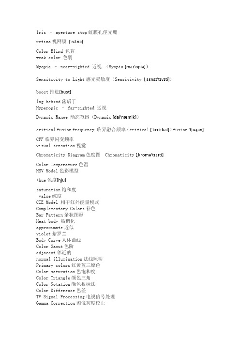
Iris -aperture stop 虹膜孔徑光珊retina 视网膜Color Blind 色盲weak color 色弱Myopia -near-sighted 近视Sensitivity to Light 感光灵敏度boost 推进lag behind 落后于Hyperopic -far-sighted 远视Dynamic Range 动态范围critical fusion frequency 临界融合频率CFF 临界闪变频率visual sensation 视觉Chromaticity Diagram 色度图Color Temperature 色温HSV Model 色彩模型(hue 色度saturation 饱和度value 纯度CIE Model 相干红外能量模式Complementary Colors 补色Bar Pattern 条状图形Heat body 热稠化approximate 近似violet 紫罗兰Body Curve 人体曲线Color Gamut 色阶adjacent 邻近的normal illumination 法线照明Primary colors 红黄蓝三原色Color saturation 色饱和度Color Triangle 颜色三角Color Notation 颜色数标法Color Difference 色差TV Signal Processing 电视信号处理Gamma Correction 图像灰度校正Conversion Tables 换算表out of balance 失衡wobble 摇晃back and forth 前后clear (white) panel 白光板vibrant 震动fuzzy 失真quantum leap 量子越迁SVGA (800x600)derive from 起源自culprit 犯人render 呈递inhibit 抑制,约束stride 大幅前进blemish 污点obstruction 障碍物scratch 刮伤substance 物质实质主旨residue 杂质criteria 标准parameter 参数adjacent 邻近的接近的asynchrony 异步cluster 串群mutually 互助得algorithm 运算法则Chromatic Aberrations 色差Fovea 小凹Visual Acuity 视觉灵敏度Contrast Sensitivity 对比灵敏度Temporal (time) Response 反应时间rendition 表演,翻译animation 活泼又生气ghost 重影Parallax 视差deficient 缺乏的不足的Display panel 显示板NG.( Narrow Gauge) 窄轨距dichroic mirror 二色性的双色性的Brewster Angle 布鲁斯特角Polarized Light 极化光Internal reflection 内反射Birefringence 双折射Extinction Ratio 消光系数Misalignment 未对准Quarter Waveplates 四分之一波片blemish 污点瑕疵Geometric 几何学的ripple 波纹capacitor 电容器parallel 平行的他tantalum 钽(金属元素) exsiccate 使干燥exsiccate 油管,软膏furnace 炉子镕炉electrolytic 电解的,由电解产生的module 模数analog 类似物out of the way 不恰当pincushion 针垫拉lateral 侧面得rectangle 长方形fixture 固定设备control kit 工具箱DVI connector DVI 数局线Vertical 垂直的horizontal 水平的interlace 隔行扫描mullion 竖框直楞sawtooth 锯齿toggle 套索钉keypad 数字按键键盘tangential 切线diagnostic tool 诊断工具sagittal direction 径向的cursor position 光标位置3Yw'/#p3'ray aberration 光线相差weighting factor 权种因子variables 变量for now 暂时,目前.眼下check box 复选框Airy disk 艾里斑exit pupil 出[射光]瞳optical path difference 光称差with respect to 关于diffraction limited 衍射极限wavefront aberration 波阵面相差spherical aberration 球面象差paraxial focus 傍轴焦点chromatic aberration 象差local coordinate system 局部坐标系统coordinate system 坐标系orthogonal 直角得,正交的conic sections 圆锥截面account for 解决,得分parabolic reflector 拋物面反射镜radius of curvature 曲率半径spherical mirror 球面镜geometrical aberration 几何相差incident radiation 入射辐射global coordinate 总体坐标in terms of 根据按照reflected beam 反射束FYI=for your information 供参考Constructive interference 相长干涉phase difference 相差achromatic singlet 消色差透镜Interferometer 干涉仪boundary constraint 边界约束,池壁效应radii 半径Zoom lenses 变焦透镜Beam splitters 分束器discrete 不连续的,分离的objective/eye lens 物镜/目镜mainframe 主机rudimentary 根本的,未发展的photographic 照相得摄影得taxing 繁重的,费力得algebra 代数学trigonometry 三角学geometry 几何学calculus 微积分学philosophy 哲学lagrange invariant 拉格朗日不变量spherical 球的field information 场信息Standard Lens 标准透镜Refracting Surface 折射面astigmatism 散光HDTV 高清晰度电视DLV ( Digital Light Valve) 数码光路真空管,简称数字光阀diffraction grating 衍射光珊field angle 张角paraxial ray trace equations 近轴光线轨迹方称back focal length 后焦距principal plane 主平面vertex 顶点,最高点astigmatism 散光,因偏差而造成的曲解或错判medial 中间的,平均的variance 不一致conic 圆锥的,二次曲线field of view 视野collimator 瞄准仪convolution 回旋.盘旋,卷积fuzzy 失真,模糊aberrated 异常的asymmetry不对称得indicative 可表示得parabolic 拋物线得suffice 足够,使满足specification 规格,说明书straightforward 易懂的,直接了当的,solidify 凝固,巩固. Constraints 约束,限制metrology 度量衡field coverage 视场,视野dictate 口述, 口授, 使听写, 指令, 指示, 命令, 规定irradiance 发光, 光辉,辐照度aerial 空气得,空中得halide 卤化物的monochromatic 单色的,单频的polychromatic 多色的aspherical 非球面的spherical 球面的alignment 列队,结盟power( 透镜) 放大率equiconvergence 同等收敛EFL(effective focal length) 有效焦距workhorse 广为应用的设备biconvex 两面凸的global optimization 整体最优化concave 凹得,凹面得cylindrical 圆柱得solid model 实体模型Modulation Transfer Function 调制传递函数in the heat of 在最激烈的时候protocol 协议,规定triplet 三重态sanity 心智健全zinc 锌,涂锌的selenide 硒化物,硒醚miscellaneous 各色各样混在一起, 混杂的, 多才多艺的versus 与... 相对polynomial 多项式的coefficient 系数explicit function 显函数" wYgi%distinct 清楚的,截然不同的emanate 散发, 发出, 发源rudimentary 根本的,未发展的intersection 角差点PRTE=paraxial ray trace equation 旁轴光线轨迹方程achromats 消色差透镜cardinal points 基本方位separations 分色片dashed 虚线blow up 放大overlay 覆盖, 覆盖图multiplayer 多层的humidity 湿度float glass 浮法玻璃square one 出发点,端点square up to 准备开打, 坚决地面对reflecting telescope 反射式望远镜diagnostic tools 诊断工具Layout plots 规划图Modulation transfer function 调制转换功能FFT 快速傅里叶变换Point spread function 点传播功能wavelength 波长angle 角度absorption 吸收system aperture 系统孔径lens units 透镜单位wavelength range 波长范围singlet lens 单业透镜spectrum 光谱diffraction grating 衍射光栅asphere 半球的LDE=Lens data editor Surface radius of curvature 表面曲率半径surface thickness 表面厚度material type 材料种类semi-diameter 半径focal length 焦距aperture type 孔径类型aperture value 孔径值field of view 视场microns 微米F, d, and C= blue hydrogen, yellow helium, red hydrogen lines, primary wavelength 主波长sequential mode 连续模式object surface 物表面The front surface of the lens 透镜的前表面stop 光阑The back surface of the lens 透镜的后表面The image surface 像表面symmetric 相对称的biconvex 两面凸的The curvature is positive if the center of curvature of the surface is to the right of the vertex. It is negative if the center of curvature is to the left of the vertex. 如果曲率中心在最高点的右边,曲率值为正, 如果曲率中心在最高点的左边,则曲率为负image plane 像平面Ray Aberration 光线相差tangential direction 切线方向sagittal direction 径向paraxial focus 旁轴的Marginal 边缘的spherical aberration 球面像差Optimization Setup 最优化调整variable 变量mathematical sense 数学角度MFE= Merit Function Editor, Adding constraints 增加约束focal length 焦矩长度operand 操作数the effective focal length 有效焦矩primary wavelength 主波长initiate 开始spot diagram 位图表Airy disk 艾里斑axial chromatic aberration 轴向色差with respect to 关于至于exit pupil 出射光瞳OPD=optical path difference 光学路径差diffraction limited 衍射极限chromatic aberration 色差chromatic focal shift 色焦距变换paraxial focus 傍轴焦点axial spherical aberration 轴向球差(longitudinal spherical aberration 纵向球差: 沿光轴方向度量的球差)lateral spherical aberration垂轴球差(在过近轴光线像点 A '的垂轴平面内度量的球差)coma 、comatic aberration 彗差meridional coma 子午彗差sagittal coma 弧矢彗差astigmatism 像散local coordinate system 本地坐标系统meridional curvature of field 子午场曲sagittal curvature of field 弧矢场曲decentered lens 偏轴透镜orthogonal 直角的垂直的conic section 圆锥截面account for 说明,占有, 得分stigmatic optical system 无散光的光学系统Newtonian telescope 牛顿望远镜parabolic reflector 抛物面镜foci 焦距chromatic aberration, 色差superpose 重迭parabola 抛物线spherical mirror 球面镜RMS=Root Mean Square 均方根wavefront 波阵面spot size 光点直径Gaussian quadrature 高斯积分rectangular array 矩阵列grid size 磨粒度PSF=Point Spread Function 点扩散函数FFT=Fast Fourier Transform Algorithm 快速傅里叶变换Cross Section 横截面Obscurations 昏暗local coordinates 局部坐标系统vignette把…印为虚光照Arrow key键盘上的箭头键refractive折射reflective反射in phase同相的协调的Ray tracing 光线追迹diffraction principles 衍射原理order effect 式样提出的顺序效果energy distribution 能量分配Constructive interference 相长干涉dispersive 色散的Binary optics 二元光学phase advance 相位提前achromatic single 消色差单透镜diffractive parameter 衍射参数Zoom lenses 变焦透镜Athermalized lenses 绝热透镜Interferometers 干涉计Beam splitter 分束器Switchable component systems 可开关组件系统common application 通用symmetry 对称boundary constraint 边界约束multi-configuration (MC) MC Editor (MCE) perturbation 动乱,动摇index accuracy 折射率准确性index homogeneity 折射率同种性index distribution 折射率分配abbe number 离差数Residual 剩余的Establishing tolerances 建立容差figure of merit 质量因子tolerance criteria 公差标准Modulation Transfer Function (MTF)调制传递函数boresight 视轴,瞄准线Monte Carlo 蒙特卡洛Tolerance operands 误差操作数conic constant ]MC1"{_qT 圆锥常数astigmatic aberration 像散误差Mechanical tilt 机械倾斜,机械倾角Tolerance Data Editor (TDE)公差资料编辑器compensator 补偿棱镜estimated system performance 预估了的系统性能iteratively 反复的,重迭的statistical dependence 统计相关性sequential ray trace model 连续光线追迹模型imbed 埋葬,埋入multiple 多样的,多重的,若干的Non-Sequential Components 不连续的组件Corner cube 角隅棱镜,三面直角透镜Sensitivity Analysis 灵敏度分析Faceted reflector 有小面的反射镜emit 发射,发出nest 嵌套overlap 交迭outer lens 外透镜brute force 强力seidel 像差系数aspect ratio 长宽比MRA 边缘光线角MRH 边缘光线高度asynchronous 不同时的,异步Apodization factor 变迹因子hexapolar 六角形dithered 高频脉冲衍射调制传递函数(DMTF ),衍射实部传递函数(DRTF ),衍射虚部传递函数(DITF ),衍射相位传递函数(DPTF ),方波传递函数(DSWM )logarithmic 对数的parity 奇偶% Uc,I e longitudinal aberrations 纵向像差赛得系数:球差(SPHA , SI),彗差(COMA , S2),像散(ASTI , S3), 场曲(FCUR , S4),畸变(DIST , S5),轴向色差(CLA , CL)和横向色差(CTR , CT)•横向像差系数:横向球差(TSPH)横向弧矢彗差(TSCO)横向子午彗差(TTCO)横向弧矢场曲(TSFC)横向子午场曲(TTFC ),横向畸变(TDIS )横向轴上色差(TLAC )纵向像差系数:纵向球差(LSPH ),纵向像散(LAST ),纵向匹兹凡场曲(LPFC ),纵向弧矢场曲(LFCS ),纵向子午场曲(LFCT )和纵向轴上色差(LAXC ),横向像散(TAST),横向匹兹凡场曲(TPFC )纵向弧矢场曲(LSFC)纵向畸变(LDIS)波前系数:球差(W040 ),彗差(W131 ),像散(W222 ),匹兹凡场曲(W220P ),畸变(W311 ),轴向色离焦项(W020 ), 轴向色倾斜(W111),弧矢场曲(W220S ),平均场曲(W220M ),子午场曲(W220T )•彗差comatic aberration 子午彗差meridional coma 弧矢彗差sagittal coma 锤形优化(Hammer Optimization)评价函数列表(Merit Function Listing)公差汇总表(Tolerance Summary)套样板(Test Plate Fitting)镜头库(Lens Catalogs)等双凸/ 等双凹(equiconvex/equiconcave)和双凸/ 双凹( biconvex/biconcave)。
原子干涉仪中激光频率和光强控制系统的设计
原子干涉仪中激光频率和光强控制系统的设计胡朝晖;杨婷;亓鲁【摘要】为了对铯原子外态干涉仪的激光束精密控制,设计了一套适用于多种需求的激光频率和光强控制系统。
该系统基于声光调制器,并集成了激光移频、光强稳定和光强调制等功能。
首先,根据原子干涉仪的原理,提出对激光的要求和指标。
接着,按照提出的要求设计了集成锁相频率合成器等硬件电路系统和LabVIEW软件控制系统。
最后,对所开发的系统进行了实验测试。
实验结果表明:系统的移频范围可控制在100~200 MHz;光强稳定性好,采用稳光系统后输出光强的波动减小为2%。
设计的这套系统功能齐全,可靠有效,实现预期目标,满足原子干涉仪对光学系统的要求。
另外此系统还可以应用到其他需要系统中,比如原子钟、原子干涉重力梯度仪等。
%In order to control laser beams precisely in a caesium atom interferometer,a laser frequency and power con-trol system which is suitable for various demands is designed. Based on an acousto-optical modulator,the system in-tegrates the functions of frequencyshift,power stabilization and modulation. Firstly,based on the principle of the at-om interferometer,the requirement of the optical part in the system is proposed. Secondly,the hardware circuit sys-tem including a phase-locked loop frequency synthesizer and the LabVIEW software control system are designed. Fi-nally,the developed system is tested. The experimental results show that the frequency shift range of the laser beam through the acousto-optical modulator is 100~200MHz;and the power fluctuation of the laser decrease to 2% using the power stabilization system. The designed system has multi-functions,achieves the desired aimsand satisfies the requirements of atom transition,matter wave interference and other processes to laser beams. In addition,the de-signed system could be applied to other systems which need to adjust and control laser beam precisely,such as atomic clock,atom interferometer gravity gradiometer and so on.【期刊名称】《激光与红外》【年(卷),期】2014(000)006【总页数】5页(P614-618)【关键词】声光调制器;原子干涉;频率合成器;频率偏移;光强控制【作者】胡朝晖;杨婷;亓鲁【作者单位】北京航空航天大学惯性技术重点实验室,北京 100191; 北京航空航天大学新型惯性仪表与导航系统技术国防重点学科实验室,北京 100191;北京航空航天大学惯性技术重点实验室,北京 100191; 北京航空航天大学新型惯性仪表与导航系统技术国防重点学科实验室,北京 100191;北京航空航天大学惯性技术重点实验室,北京 100191; 北京航空航天大学新型惯性仪表与导航系统技术国防重点学科实验室,北京 100191【正文语种】中文【中图分类】TP212.11 引言由于和中子、光子一样具有波粒二象性,原子可以实现类似光学干涉仪的原子干涉仪。
Optical Interferometry词汇-1
Optical Interferometry Aaberration of light, 2aberrations, 119analysis, 123achromatic fringes, 31, 56achromatic phase shifting, 103, 153active elements for interferometers, 216 adaptive optics, 207, 237aether drift, 2, 239, 240Airy formula, 60, 65Airy function, 159aliasing, 179noise, 182amplitude, 9complex, 10amplitude division, 14, 23analytic signal, 36angle measurements, 118apodization, 178argon-ion laser, 79aspheric surfaces, 136testing with CGHs, 136astrometry, 235atomic cascade, 254, 256autocorrelation, 291of a random function, 292Bbeamsplitters, 24polarization effects, 58with single photons, 256beats with light waves, 5, 84at the single-photon level, 262Bell’s inequality, 7interferometric tests, 277perfect correlations, 280unbalanced interferometers, 279 birefringent filters, 163Bragg grating sensors, 195Brewster angle, 295, 296Brewster’s fringes, 68BSOstudy of vibrating objects, 215Ccarbon-dioxide laser, 79exact fractions, 107frequency chain, 112frequency stabilization, 90testing rough surfaces, 138“cat’s-eye” reflectors, 183channeled spectra, 29, 32circular frequency, 9closure phase, 237coherence, 3, 35and visibility of fringes, 41complex degree, 40coherence (cont.)effects in two-beam interferometers,51fourth-order, 267higher-order, 3, 50, 51, 225in the space-frequency domain, 49intensity correlation, 3spatial, 43temporal, 47visibility of fringes, 55coherence length, 48of laser light, 83coherence time, 48combustion studies, 3common-path interferometers, 124 comparison of laser frequencies, 84 compensating plate, 25compensationfor polarization, 58for a range of wavelengths, 32 complex amplitude, 10complex representation of light waves,10, 35 computer-aided fringe analysis, 97 computer-generated holograms, 305testing aspheric surfaces, 136 confocal resonator, 81modes, 81convolution, 290correlation, 290cross-power spectrum, 42cross-spectral density function, 49Ddefinition of the metre, 2, 111 degeneracy parameter, 85degree of coherence, 40delay, 51, 54, 56delta function, 291diffusion, 27diode lasers, 80frequency stabilization, 90diode-laser interferometers, 200Dirac delta function, 291dispersive mediaeffects, 38, 56visibility of fringes, 38 displacementsreal-time measurements, 116 Doppler velocimetry, 5, 201double-frequency grating, 130double-passed fringes, 76down-conversion, 254dye lasers, 79wavelength measurement, 165wavelength selection, 164dynamic wavelength meters, 165Eechelon, 3, 158electronic phase measurements,4, 93, 148 end standards, 105etalon, 3, 61, 159etendue, 3, 157, 161etendue advantage, 173exact fractions, 107extended sourcelocalization of fringes, 19FFabry–Perot interferometer, 3, 61,108, 158 finesse, 62multiple, 162multiple-pass, 163scanning, 159spherical-mirror, 161Fabry–Perot sensors, 194fast Fourier transform, 184, 306 FECO fringes, 67for surface profiling, 68Felgett advantage, 175fiber interferometers, 5, 191rotation sensing, 191fiber-optic sensors, 191, 193applications, 195low-coherence, 194multiplexed, 197finesse, 62Fizeau fringes, 16Fizeau interferometer, 119flatness test, 119, 134test for parallelism, 120flatness test, 119, 134fluid flow, 3, 27four-wave mixing, 213Fourier imaging, 129Fourier transform, 289Fourier-transform spectroscopy, 3, 5,56, 173 aliasing, 179, 182apodization, 178applications, 184computation, 184field widening, 181interferometers, 182noise, 181phase correction, 181prefiltering, 182resolution, 178sampling, 179source and detector size, 180theory, 175fourth-order coherence, 267fourth-order interference, 267geometric phase, 274nonclassical, 267frequency, 9circular, 9frequency chain, 170frequency comb, 171frequency comparison, 84frequency measurements, 111frequency comb, 171heterodyne techniques, 5, 169, 170 frequency stabilization, 86diode lasers, 90with an etalon, 86on the Lamb dip, 88polarization, 86saturated absorption, 88saturated fluorescence, 90transverse Zeeman laser, 86 frequency standards, 170frequency-doubling, 209Fresnel drag, 2Fresnel formulas, 295Fresnel’s mirrors, 12Fresnel–Kirchhoff integral, 293fringe analysiscomputer-aided, 97Fourier-transform techniques, 97 fringe counting, 93fringe-counting interferometers, 5 fringesachromatic, 31Brewster’s, 68double-passed, 76effects of source size, 20of equal chromatic order, 66of equal inclination, 16, 26of equal thickness, 17, 26, 119half-width, 62influence of source size, 55localization, 18, 55localized, 19, 21, 26, 28multiple-beam, 59nonlocalized, 18, 25, 26in a plane-parallel plate, 21of superposition, 68, 107, 108, 110three-beam, 73in a thin film, 17in a wedged thin film, 21white light, 29Ggeometric phase, 103, 154, 257in fourth-order interference, 274at the single-photon level, 258with single-photon states, 259 grating interferometers, 129grating sensors, 195gravitation, 239gravitational strain, 242gravitational waves, 241gravitational-wave detectors, 7, 242 grazing incidence interferometry, 138 group delay, 56group refractive index, 32, 38, 109group velocity, 37HHaidinger’s rings, 16helium–neon laser, 4, 79frequency stabilization, 86, 111single-frequency operation, 83 heterodyne interferometry, 5, 95, 148 thermal expansion, 116heterodyne stellar interferometry, 227,229 heterodyne techniques, 5, 169frequency comparisons, 84frequency measurements, 111, 169,170 rotation sensing, 190Hewlett-Packard interferometer, 94high-reflectance coatings, 61higher-order coherence, 3, 50, 51, 225 hole burning, 88holograms, 303binary, 306computer-generated, 305off-axis, 303hyper-telescope, 235Iinfrared interferometry, 107, 138 instrumental function, 157intensity, 10mutual, 42optical, 11intensity correlations, 6, 224intensity interferometer, 6, 223, 267 interferenceby amplitude division, 14fourth-order, 267with independent sources, 4, 260order, 12with partially coherent light, 40, 55in a plane-parallel plate, 14, 21in a plate of variable thickness, 16quantum picture, 254, 288in separated interferometers, 271at the single-photon level, 253, 260with single-photon states, 256in a thin film, 17of two monochromatic waves, 11by wavefront division, 12in a wedged thin film, 21with white light, 29 interference microscopes, 3, 143common path, 143interference order, 12with dispersive media, 38 interference spectroscopy, 3, 157 interferential color photography, 33 interferogram analysisphase unwrapping, 122polynomial fitting, 124Zernike polynomials, 124 interferometric sensors, 189 interferometry below the SQL, 251JJamin interferometer, 108Jones calculus, 57, 299KKösters interferometer, 10586Kr standard, 111LLamb-dip stabilization, 88lambda meter, 165laser beams, 91laser modes, 80laser speckle, 91laser-Doppler velocimetry, 5, 201 laser-feedback interferometers, 198 lasers, 4, 79beam expansion, 91beats, 5, 84confocal resonator, 81etalon stabilized, 86feedback effects, 86, 92frequency comparison, 84frequency measurements, 5, 111, 170frequency stabilization, 86, 111, 170frequency standards, 170frequency-doubling, 209generalized spherical resonator, 81for interferometry, 79longitudinal modes, 82measurement of line widths, 169modes, 80polarization-stabilized, 86safety precautions, 92single-frequency operation, 83spot size, 81stabilization by saturated absorption,88 stabilization by saturatedfluorescence, 90stabilization on the Lamb dip, 88transverse Zeeman, 86lateral shearwith plane wavefronts, 144with spherical wavefronts, 146lateral shearing interferometers, 125analysis of interferograms, 125Lau effect, 129length measurements, 105changes in length, 116exact fractions, 107integral order, 106with lasers, 113sinusoidal wavelength scanning, 115two-wavelength interferometry, 113wavelength-scanning, 114LIGO, 245line standards, 105linear systemstwo-dimensional, 289Lippmann color photography, 33liquid reference surface, 120Lloyd’s mirror, 13localization of fringes, 18, 55in multiple-beam interference, 65secondary regions, 55localized fringes, 21, 26, 28low-coherence sensors, 194Lummer–Gehrcke plate, 3, 158Lyot filter, 163MMach–Zehnder interferometer, 24, 26 lateral shearing, 125 magnetometers, 206measurement of the metre, 2, 109 metredefinition, 2, 5, 111, 112measurement, 2, 109realization, 170Michelson interferometer, 24double-passed, 77lateral shearing, 125 Michelson’s stellar interferometer,6, 221 Michelson–Morley experiment,2, 7, 239 microscopy, 3, 143Mirau interferometer, 143 modulation transfer function, 141 moire fringes, 129monochromatic light waves, 10 multiple Fabry–Perotinterferometer, 162multiple-beam fringesof equal chromatic order, 66of equal thickness, 64localization, 65in a plane-parallel plate, 59by reflection, 63of superposition, 68, 70, 107, 108surface profiling, 66testing flat surfaces, 119by transmission, 60multiple-beam interference, 59 multiple-pass Fabry–Perotinterferometer, 163multiplex advantage, 173, 175, 185 multiplexed sensors, 197mutual coherence function, 39integrated, 49mutual intensity, 42NNd:YAG laser, 80, 209Newton’s rings, 1Nomarski interferometer, 147 nonclassical light, 51, 254, 267 nonlinear effects, 5, 209optical fibers, 219nonlinear interferometers, 5, 209measurement of susceptibility,217optical switches, 219nonlinear susceptibilities, 217 nonlocalized fringes, 18, 25, 26 nulling interferometers, 236Ooblique incidence interferometry, 138 off-axis hologram, 303optical feedback, 86optical fibersnonlinear effects, 219optical intensity, 11quasi-monochromatic source, 36 optical multiplication, 107optical path, 10optical path difference, 12, 24 optical switches, 6, 219optical testing, 3, 119analysis of aberrations, 123polynomial fitting, 124Zernike polynomials, 124 optical transfer function, 139order of interference, 12with dispersive media, 38PPancharatnam phase, 103, 153, 301 parallelism test, 120parametric down-conversion, 254 phase ambiguities, 151phase measurementselectronic techniques, 93, 148 phase shifting, 5, 98achromatic, 103, 153error-correcting algorithms, 101by frequency shifting, 102noise and quantization errors, 135polarization techniques, 103simultaneous measurements, 103for surface profiling, 149systematic errors, 135techniques, 102for white-light interferometry, 153 phase unwrapping, 122phase velocity, 37phase-conjugate imagingvibrating objects, 215phase-conjugate interferometers, 6, 213 phase-conjugating mirrors, 213phase-locked interferometry, 96measurements of vibrations, 118 photoelectric settings, 93photon bunching, 254 photorefractive oscillators, 217plane-parallel plateinterference, 21multiple-beam interference, 59 plasmas, 27Poincaré sphere, 301point-diffraction interferometer, 132 phase shifting, 133for UV optics, 133polarizationcompensation in interferometers, 58effects in two-beaminterferometers, 57Jones calculus, 57of light, 1with metal film beamsplitters, 58 polarization interferometers, 144 polarization-stabilized laser, 86power spectrum, 292propagation constant, 9Qquantum cryptography, 281quantum effects, 7quantum eraser, 7, 284quantum limits, 246quasi-monochromatic light, 35Rradial shearing interferometers, 127analysis of interferograms, 128using birefringent lenses, 147using Fresnel zone plates, 132random functions, 291autocorrelation, 292power spectrum, 292Rayleigh interferometer, 23, 108 recycling, 243reflection at a surface, 295refractive indexof air, 107, 166group, 32, 38resolving power of a spectroscope, 157ring interferometers, 191rotation sensing, 191ring lasers, 190Ronchi interferometer, 129rotation sensors, 189fiber-optic, 191rotational shearing interferometers, 127 rough surfaces, 138ruby laser, 4, 80SSagnac interferometer, 24, 28, 31, 143fiber-optic, 191lateral shearing, 125for rotation sensing, 189saturated absorption, 88saturated fluorescence, 90Savart polariscope, 144scanning Fabry–Perot interferometer,159, 162 scatter plate, 24birefringent, 132computer generated, 132scatter-plate interferometer, 131second-harmonic interferometers, 6, 209 critical phase-matching, 212 sensors, 189fiber-optic, 191, 193shear, 51, 54, 55lateral, 125, 144, 146radial, 127, 147reversal, 127rotational, 127shearing interferometers, 124for OTF measurements, 140shift, 51, 54, 55sigma-meter, 167single-photon interference, 253single-photon state, 254sinusoidal phase modulation, 104 sinusoidal wavelength scanning, 115 source shear, 52, 55source shift, 52, 54source-size effects, 20, 45, 47, 55visibility of fringes, 55space interferometers, 237, 246space-time, 239spatial coherence, 43spatial filter, 91, 137speckle, 307dimensions, 307statistics, 307Young’s fringes, 234, 308speckle holography, 6, 234speckle interferometry, 6, 232speckle patternselimination, 91spectral bandwidth effects, 56spectral coherence, 56spectral interference law, 50spectrally resolved interferometry, 155 speed of light, 5, 112, 239spherical Fabry–Perot interferometer,161 defocused, 162scanning, 162squeezed states, 6, 248standard quantum limit, 216, 246interferometry below the SQL, 251 standing waves, 33static wavelength meters, 167stellar interferometers, 6, 221adaptive optics, 237astrometry, 235fiber-optic links, 238heterodyne, 6, 227intensity interferometer, 223long-baseline, 230Michelson’s, 6, 221, 226nulling interferometers, 236polarization effects, 238telescope arrays, 236stellar speckle interferometry, 6, 232 stimulated emission, 4Stokes relations, 63, 296, 297sub-Nyquist interferometry, 136 subaperture testing, 135 superposition fringes, 68, 107, 108, 110 superposition states, 264surface profiling, 3errors with white light, 156with multiple-beam fringes, 66phase ambiguities, 151by phase-shifting, 149spectrally resolved interferometry,155using FECO fringes, 67with white light, 151surface velocities, 202TTalbot effect, 129telescope arrays, 236temporal coherence, 47testingabsolute flatness, 134aspheric surfaces, 136with CGHs, 136computerized methods, 133optical surfaces, 3, 119rough surfaces, 138small-scale irregularities, 134sources of error, 135sub-Nyquist interferometry, 136subaperture tests, 135thermal expansion measurements, 116 thin filmsmultiple-beam fringes, 64two-beam fringes, 17third-order susceptibility, 217three-beam interference, 73tilt, 51, 54transmission at a surface, 295transverse Zeeman laser, 86tunnelingdispersion cancelation, 286single-photon, 285time, 287two-beam interference, 9two-beam interferometers, 23coherence effects, 51complementary representation, 52effects of dispersive media, 38influence of source size, 55polarization effects, 57spectral bandwidth effects, 56spectral coherence, 56two-dimensional linear systems, 289two-grating interferometer, 130two-photon interference, 277quantum cryptography, 281spectral effects, 284using two down-converters, 282two-wavelength interferometry, 113,117, 136, 151 Twyman–Green interferometer, 121Uunequal-path interferometers, 122Vvan Cittert–Zernike theorem, 45, 49,55, 221 vibration measurements, 118, 204phase-conjugate imaging, 215phase-locked interferometry, 118visibility of fringes, 12with a circular source, 47and degree of coherence, 41, 55with dispersive media, 38, 56with a rectangular source, 47secondary maxima, 55and source size, 21, 55and spectral bandwidth, 56superposition fringes, 70, 73Wwave groups, 36wave theory of light, 1wavefront aberrations, 119analysis, 123polynomial fitting, 124Zernike polynomials, 124 wavefront division, 12, 23 wavelength, 9wavelength meters, 165dynamic, 165static, 167wavelength-scanning interferometry, 114, 151white-light fringes, 29white-light interferometryachromatic phase-shifting, 153phase-shifting, 153sources of errors, 156for surface profiling, 151 Wiener–Khinchin theorem, 48, 291 Wollaston prism, 146YYoung’s double slit, 13Young’s fringes, 39formed by double star, 234formed by speckle patterns, 308with a source of finite size, 47 ZZernike polynomials, 124zone-plate interferometer, 132。
迈克尔逊干涉仪实验报告
迈克尔逊干涉仪实验报告英文回答:Michelson Interferometer Experiment Report。
Introduction。
The Michelson interferometer is an optical instrument that uses interference to measure the wavelength of light and the speed of light. It was invented by Albert A. Michelson in 1881. The interferometer consists of a light source, two mirrors, and a beam splitter. The light source is split into two beams by the beam splitter. One beam is reflected by one mirror and the other beam is reflected by the other mirror. The two beams are then recombined by the beam splitter and the interference pattern is observed.Methods。
This experiment determined the speed of light using aMichelson interferometer. The following apparatus was used: 1A Michelson interferometer。
2A helium-neon laser。
3A power supply。
4A photodetector。
5A digital oscilloscope。
通信工程专业英语Unit9:WDM

Application scenarios of WDM
• Backbone networks: WDM technology is widely used in backbone networks to provide high-speed and large-capacity data transmission services. It can effectively improve the network capacity and transmission speed, and is an important technology to support the development of the Internet.
The Development History of WDM
The first WDM system was developed in the early 1970s, but it was not widely used until the 1990s due to technical difficulties and high cost.
Frequency-division Multiplexing (FDM)
In FDM, different optical signals are generated at different frequencies,
allowing them to be transmitted simultaneously through the same
Communication Engineering Professional English Unit9: WDM
目录
• introduction • The basic principles of WDM • Key Technologies of WDM • The advantages and challenges
光学专业英语词汇总结
amplitude 振幅
phase 相位
wavenumber 波数
wavefront 波前
wavevector 波矢
envelope 包络
Wave envelope 波包
Wave packet theory 波包理论
quarter wave plate 四分之一波片
grating 光栅
absorption 吸收
Fiber 光纤
Cladding 包层
Perfect image 完善像
Object(image) space 物(像)空间
magnification 放大率
Parallel plate 平行平板
focal plane 焦平面
stop 光阑
pupil 光瞳
ray tracing 光线追迹
Incident beam 入射光
电通量密度 磁通量密度
电位移 自由空间
介质 线性的 色散的 非色散的 各向同性的 各向异性的
refractive index 折射率
absorption coefficient 吸收系数
phase velocity 相速度
group velocity 群速度
Attenuation 衰减
alumina 氧化铝
Bell inequality 贝尔不等式
teleportation 隐形传态、离物传态
quantum cryptography 量子密码
Vocabulary 9
frequency conversion 频率转换
Down conversion 下转换
Parametric process 参量过程
Nonparametric process 非参量过程
光学专业英语
Iris – aperture stop虹膜孔俓光珊retina视网膜[ˈrɛtnə]Color Blind 色盲weak color 色弱Myopia – near-sighted 近视(Myopia[maɪˈopiə])Sensitivity to Light感光灵敏度(Sensitivity [ˌsɛnsɪˈtɪvɪti])boost推进[bust]lag behind落后于Hyperopic – far-sighted 远视Dynamic Range 动态范围(Dynamic[daiˈnæmik])critical fusion frequency 临界融合频率(critical[ˈkrɪtɪkəl])fusionˈfjuʒən]CFF临界闪变频率visual sensation视觉Chromaticity Diagram色度图 Chromaticity[ˌkroməˈtɪsɪti]Color Temperature色温HSV Model色彩模型(hue色度[hju]saturation饱和度value纯度CIE Model 相干红外能量模式Complementary Colors补色Bar Pattern条状图形Heat body 热稠化approximate近似violet紫罗兰Body Curve人体曲线Color Gamut色阶adjacent邻近的normal illumination法线照明Primary colors红黄蓝三原色Color saturation色饱和度Color Triangle颜色三角Color Notation颜色数标法Color Difference色差TV Signal Processing电视信号处理Gamma Correction图像灰度校正Conversion Tables换算表out of balance失衡wobble摇晃back and forth前后clear (white) panel白光板vibrant震动fuzzy失真quantum leap量子越迁SVGA (800x600)derive from起源自culprit犯人render呈递inhibit抑制,约束stride大幅前进blemish污点obstruction障碍物scratch刮伤substance物质实质主旨residue杂质criteria标准parameter参数adjacent邻近的接近的asynchrony异步cluster串群mutually互助得algorithm运算法则Chromatic Aberrations色差Fovea小凹Visual Acuity视觉灵敏度Contrast Sensitivity对比灵敏度Temporal (time) Response反应时间rendition表演,翻译animation活泼又生气ghost重影Parallax视差deficient缺乏的不足的Display panel显示板NG.( Narrow Gauge)窄轨距dichroic mirror二色性的双色性的Brewster Angle布鲁斯特角Polarized Light极化光Internal reflection内反射Birefringence 双折射Extinction Ratio 消光系数Misalignment 未对准Quarter Waveplates四分之一波片blemish污点瑕疵Geometric几何学的ripple波纹capacitor电容器parallel平行的他tantalum钽(金属元素)exsiccate使干燥exsiccate油管,软膏furnace炉子镕炉electrolytic电解的,由电解产生的module模数analog类似物out of the way不恰当pincushion针垫拉lateral侧面得rectangle长方形fixture固定设备control kit工具箱DVIconnector DVI数局线Vertical垂直的horizontal 水平的interlace隔行扫描mullion竖框直楞sawtooth锯齿[ˈsɔtuθ]toggle套索钉keypad数字按键键盘tangential切线diagnostic tool诊断工具sagittal direction径向的sagittal[ˈsædʒɪtl]cursor position光标位置3Yw'/#p3`ray aberration光线相差weighting factor权种因子variables变量for now暂时,目前.眼下check box复选框Airy disk艾里斑exit pupil出[射光]瞳optical path difference光称差with respect to关于diffraction limited衍射极限wavefront aberration波阵面相差spherical aberration球面象差paraxial focus傍轴焦点chromatic aberration象差local coordinate system局部坐标系统coordinate system坐标系orthogonal直角得,正交的conic sections圆锥截面account for解决,得分parabolic reflector拋物面反射镜radius of curvature曲率半径spherical mirror球面镜geometrical aberration几何相差incident radiation入射辐射global coordinate总体坐标in terms of根据按照reflected beam反射束FYI=for your information供参考Constructive interference相长干涉phase difference相差achromatic singlet消色差透镜Interferometer干涉仪boundary constraint边界约束,池壁效radii半径Zoom lenses变焦透镜Beam splitters分束器discrete不连续的,分离的objective/eye lens物镜/目镜mainframe主机rudimentary根本的,未发展的photographic照相得摄影得taxing繁重的,费力得algebra代数学trigonometry三角学geometry几何学calculus微积分学philosophy哲学lagrange invariant拉格朗日不变量spherical球的field information场信息Standard Lens标准透镜Refracting Surface折射面astigmatism散光HDTV高清晰度电视DLV ( Digital Light Valve)数码光路真空管,简称数字光阀diffraction grating衍射光珊field angle张角paraxial ray trace equations近轴光线轨迹方称back focal length后焦距principal plane主平面vertex顶点,最高点astigmatism散光,因偏差而造成的曲解或错判medial中间的,平均的variance不一致conic圆锥的,二次曲线field of view视野collimator瞄准仪convolution回旋.盘旋,卷积fuzzy失真,模糊aberrated异常的[ˈæbəˌretɪd]asymmetry不对称得[eˈsɪmɪtri]indicative可表示得[ɪnˈdɪkətɪv]parabolic拋物线得[ˌpærəˈbɑlɪk]suffice足够,使满足specification规格,说明书[ˌspɛsəfɪˈkeʃən]straightforward易懂的,直接了当的[stretˈfɔrwəd],solidify凝固,巩固.Constraints 约束,限制metrology度量衡field coverage视场,视野dictate口述, 口授, 使听写, 指令, 指示, 命令, 规定irradiance发光, 光辉,辐照度aerial空气得,空中得halide卤化物的monochromatic单色的,单频的polychromatic多色的aspherical非球面的spherical球面的alignment列队,结盟power(透镜)放大率equiconvergence 同等收敛EFL(effective focal length)有效焦距workhorse广为应用的设备biconvex两面凸的global optimization整体最优化concave凹得,凹面得cylindrical圆柱得solid model实体模型Modulation Transfer Function调制传递函数in the heat of在最激烈的时候protocol协议,规定triplet三重态sanity心智健全zinc锌,涂锌的selenide 硒化物,硒醚miscellaneous各色各样混在一起, 混杂的, 多才多艺的versus与...相对polynomial多项式的coefficient系数explicit function显函数" wYgi%distinct清楚的,截然不同的emanate散发, 发出, 发源rudimentary根本的,未发展的intersection角差点PRTE=paraxial ray trace equation旁轴光线轨迹方程achromats 消色差透镜cardinal points基本方位separations分色dashed虚线blow up放大overlay覆盖,覆盖图multiplayer 多层的humidity 湿度float glass浮法玻璃square one 出发点,端点square up to 准备开打,坚决地面对reflecting telescope 反射式望远镜diagnostic tools诊断工具Layout plots规划图Modulation transfer function调制转换功能FFT快速傅里叶变换Point spread function点传播功能wavelength波长angle角度absorption吸收system aperture系统孔径lens units透镜单位wavelength range波长范围singlet lens单业透镜spectrum光谱diffraction grating衍射光栅asphere半球的LDE=Lens data editor Surface radius of curvature表面曲率半径surface thickness表面厚度material type材料种类semi-diameter半径focal length焦距aperture type孔径类型aperture value孔径值field of view视场microns微米F, d, and C= blue hydrogen, yellow helium, red hydrogen lines, primary wavelength主波长sequential mode连续模式object surface物表面The front surface of the lens透镜的前表面stop光阑The back surface of the lens透镜的后表面The image surface像表面symmetric相对称的biconvex两面凸的The curvature is positive if the center of curvature of the surface is to the right of the vertex. It is negative if the center of curvature is to the left of the vertex.如果曲率中心在最高点的右边,曲率值为正,如果曲率中心在最高点的左边,则曲率为负image plane像平面Ray Aberration光线相差tangential direction切线方向sagittal direction径向paraxial focus旁轴的Marginal边缘的spherical aberration球面像差Optimization Setup最优化调整variable变量mathematical sense数学角度MFE= Merit Function Editor, Adding constraints增加约束focal length焦矩长度operand操作数the effective focal length有效焦矩primary wavelength主波长initiate开始spot diagram位图表Airy disk艾里斑axial chromatic aberration轴向色差with respect to关于至于exit pupil出射光瞳OPD=optical path difference光学路径差diffraction limited衍射极限chromatic aberration色差chromatic focal shift色焦距变换paraxial focus傍轴焦点axial spherical aberration轴向球差(longitudinal spherical aberration 纵向球差:沿光轴方向度量的球差) lateral spherical aberration垂轴球差(在过近轴光线像点A‵的垂轴平面内度量的球差)coma、comatic aberration彗差meridional coma子午彗差sagittal coma弧矢彗差astigmatism像散local coordinate system本地坐标系统meridional curvature of field子午场曲sagittal curvature of field弧矢场曲decentered lens偏轴透镜orthogonal直角的垂直的conic section圆锥截面account for说明,占有,得分stigmatic optical system无散光的光学系统Newtonian telescope牛顿望远镜parabolic reflector抛物面镜foci焦距chromatic aberration,色差superpose重迭parabola抛物线spherical mirror球面镜RMS=Root Mean Square均方根wavefront波阵面spot size光点直径Gaussian quadrature高斯积分rectangular array矩阵列grid size磨粒度PSF=Point Spread Function点扩散函数FFT=Fast Fourier Transform Algorithm快速傅里叶变换Cross Section横截面Obscurations昏暗local coordinates局部坐标系统vignette把…印为虚光照Arrow key键盘上的箭头键refractive折射reflective反射in phase同相的协调的Ray tracing光线追迹diffraction principles衍射原理order effect式样提出的顺序效果energy distribution能量分配Constructive interference相长干涉dispersive色散的Binary optics二元光学phase advance相位提前achromatic single消色差单透镜diffractive parameter衍射参数Zoom lenses变焦透镜Athermalized lenses绝热透镜Interferometers干涉计Beam splitter分束器Switchable component systems可开关组件系统common application通用symmetry对称boundary constraint边界约束multi-configuration (MC) MC Editor (MCE) perturbation动乱,动摇index accuracy折射率准确性index homogeneity折射率同种性index distribution折射率分配abbe number离差数Residual剩余的Establishing tolerances建立容差figure of merit质量因子tolerance criteria公差标准Modulation Transfer Function (MTF)调制传递函数boresight视轴,瞄准线Monte Carlo蒙特卡洛Tolerance operands误差操作数conic constant ]MC1"{_qT 圆锥常数astigmatic aberration像散误差Mechanical tilt机械倾斜,机械倾角Tolerance Data Editor (TDE)公差资料编辑器compensator补偿棱镜estimated system performance预估了的系统性能iteratively反复的,重迭的statistical dependence统计相关性sequential ray trace model连续光线追迹模型imbed埋葬,埋入multiple多样的,多重的,若干的Non-Sequential Components不连续的组件Corner cube角隅棱镜,三面直角透镜Sensitivity Analysis灵敏度分析Faceted reflector有小面的反射镜emit发射,发出nest嵌套overlap交迭outer lens外透镜brute force强力seidel像差系数aspect ratio长宽比MRA边缘光线角MRH边缘光线高度asynchronous不同时的,异步Apodization factor变迹因子hexapolar六角形dithered高频脉冲衍射调制传递函数(DMTF),衍射实部传递函数(DRTF),衍射虚部传递函数(DITF),衍射相位传递函数(DPTF),方波传递函数(DSWM)logarithmic对数的parity奇偶% Uc,I e longitudinal aberrations 纵向像差赛得系数:球差(SPHA,SI)彗差(COMA,S2),像散(ASTI,S3),场曲(FCUR,S4),畸变(DIST,S5),轴向色差(CLA,CL)和横向色差(CTR,CT).横向像差系数:横向球差(TSPH),横向弧矢彗差(TSCO),横向子午彗差(TTCO),横向弧矢场曲(TSFC),横向子午场曲(TTFC),横向畸变(TDIS)横向轴上色差(TLAC)。
optical tweezers
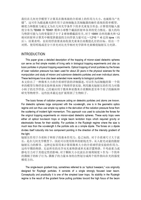
我们在几何光学模型下计算其在微米级的介质球上的作用力大小,也被称为“光镊”。
这可作为描述激光阱作用于活体细胞及其细胞器的操作系统的简单模型。
梯度力和散射力被定义为在几何光学条件下的多光束复合形态。
计算使用输入强度分布为TEM00和TEM01模和小球整个截面折射率各异的受力情况。
强大的均匀势阱可能与力的变量因子小于2球体横截面有关。
对于10MW功率的激光和1.2相对折射率计算其中梯度阱最弱的方向俘获力量可达〜1.2*10 ^ -6达因dyne(向后)。
结果表明,良好的俘获要求高收敛光束来自高数值孔径的目标。
给出一个对照,使用明场或差分干涉光对比光学相衬光学阱单光束梯度辐射压力光阱。
INTRODUCTIONThis paper gives a detailed description of the trapping of micron-sized dielectric spheres can serve as first simple models of living cells in biological trapping experiments and also as basic particles in physical trapping experiments. Optical trapping of small particles by the forces of laser radiation pressure has been used for about 20 years in the physical sciences for the manipulation and study of micron and submicron dielectric particles and even individual atoms. These techniques have also been extended more recently to biological particles.本文给出了一种微米大小的介质球俘获的详细描述,可以作为活细胞的第一个简单的模型生物俘获实验和基本粒子物理俘获实验。
用干涉法测量传递函数
Copyright 2005 Society of Photo-Optical Instrumentation Engineers. This paper will be published in Proceedings of SPIE and is made available as an electronic preprint with permission of SPIE. One print or electronic copy may be made for personal use only. Systematic or multiple reproduction, distribution to multiple locations via electronic or other means, duplication of any material in this paper for a fee or for commercial purposes, or modification of the content of the paper are prohibited.Interpreting interferometric height measurementsusing the instrument transfer functionPeter de Groot and Xavier Colonna de LegaZygo CorporationLaurel Brook Rd, Middlefield, CT 06455, USA1 IntroductionOf the various ways of characterizing a system, one of the most appeal-ing is the instrument transfer function or ITF. The ITF describes systemresponse in terms of an input signal’s frequency content. An every-dayexample is the graph of the response of an audio amplifier or media playerto a range of sound frequencies.It is natural therefore to characterize surface profiling interferometersaccording to their ITF. This is driven in part by developments in precisionoptics manufacturing, which increasingly tolerance components as a func-tion of spatial frequency [1]. Metrology tools must faithfully detect pol-ishing errors over a specified frequency range, and so we need to knowhow such tools respond as a function of lateral feature size.Here we review the meaning, applicability, and calculation of the ITFfor surface profiling interferometers. This review leads to useful rules ofthumb as well as some cautions about what can happen when we apply theconcept of a linear ITF to what is, fundamentally, a nonlinear system. Ex-perimental techniques and example results complete the picture.Our approach is informal, as is appropriate for a conference paper. Thefoundation for a rigorous understanding of the ITF is well documented inthe literature, including the well-known books by Goodman [2].2 Linear systemsITF is most commonly understood to apply to linear systems, whichshare certain basic properties that lend themselves naturally to frequencyanalysis. Principally, the response of a linear system is the sum of the re-sponses that each of the component signals would produce individually.2Thus if two frequency components are present in an input signal, we can propagate them separately and add up the results.Another property of linear systems is that the response for a given spa-tial frequency f along a coordinate x is given by a corresponding ITF value characteristic of the system alone, independent of signal magnitude and phase. Thus to determine the output g ′ given an input g , we write()()()ITF G f f G f ′=⋅ (1)where()(){}()(){}G f FT g x G f FT g x =′′= (2) and the Fourier Transform is defined by{}{}()exp 2FT ifx dx ∞−∞=−π∫. (3)This is a powerful way of predicting system response to diverse stimuli.3 OTF for optical imagingA familiar ITF is the optical transfer function or OTF, which describeshow an optical system reproduces images at various spatial frequencies. The modulus of the OTF is the modulation transfer function (MTF).An approach to the OTF is to consider the effect of a limiting aperture inthe pupil plane of an unaberrated imaging system. A plane wavefront gen-erated by a point source illuminates a perfectly flat object (top left diagram in Figure 1). The object reflectivity profile may be dissected in terms of sinusoidal amplitude gratings over a range of spatial frequencies. Allow-ing each constituent grating its own DC offset, each grating generates three diffraction orders, -1, 0, 1. The separation of the ±1 orders in the pupil plane is proportional to the grating frequency.According to the Abbé principle, if the pupil aperture captures all of thediffracted beams, then the system resolves the corresponding frequency. Assuming that the optical system is perfect and that it obeys the sine con-dition, the principle rays in Figure 1 show that the optical system faithfully reproduces the amplitude reflectivity frequency content up to a limiting3frequency NA /λ. This coherent imaging MTF is therefore a simple rec-tangle, as shown in the top-right of Figure 1.1Spatial FrequencyMTF100Coherent illuminationFigure 1: Illustration of incoherent and coherent light imaging systems (left) and thecorresponding MTF curves (right).The reasoning is much the same for an extended, incoherent source (lower left of Figure 1) [3]; although the results are very different. The various source points in the pupil generate overlapping, mutually-incoherent images that add together as intensities . As we move across the pupil, the obscurations of the ±1 diffraction orders vary. The calculation reduces to the autocorrelation of the pupil plane light distribution, which for a uniformly-filled disk is()()()()21MTF cos sin cos f f NA π−=φ−φφ⎡⎤⎣⎦φ=λ. (4)This curve, shown in the lower right of Figure 1, declines gradually from zero out to twice the coherent frequency limit. Incoherent imaging is often preferred in microscopes because of this higher frequency limit and softer transfer function, which suppresses ringing and other coherent artifacts. Note that coherent systems are linear in amplitude and incoherent sys-tems are linear in intensity . This leads to an ambiguity in the ITF for par-tially coherent light, addressed pragmatically by the apparent transfer function, which uses the ratio of the output and input modulations for sin-gle, isolated frequencies while simply ignoring spurious harmonics [4].44 ITF for optical profilersThe ITF is so useful that it is tempting to use it even for systems that are explicitly nonlinear. Traditional tactile tools, for example, are nonlinear at high spatial frequencies because of the shape of the stylus; but their re-sponse is often plotted as a linear ITF [5]. If we are lucky, we find that over some limited range the system is satisfactorily approximated as linear. This is the case of optical profilers as well, with appropriate cautions.0.51S t r e n g t h10.500.51Pupil plane coordinate S t r e n g t hFigure 2: Comparison of the diffracted beams from amplitude (upper) and phase (lower) gratings illustrates the complex diffraction behavior of height objects, leading to nonlinearresponse when profiling surface heights.Returning to the elementary concept of constituent gratings, consider coherent illumination of an object that has uniform reflectivity but a vary-ing height. The surface impresses upon the incident wavefront a phase profile that propagates through the system to the image plane as a complex amplitude. Using any one of the known interferometric techniques, we can estimate the imaged phase profile and convert this back to height.Just as before, a Fourier Transform of the object wavefront yields sinu-soidal phase gratings over a range of spatial frequencies. Each grating generates diffracted beams, although Figure 2 shows that for phase grat-ings, the light spreads into higher angles than just the -1, 0, 1 orders pre-sent with amplitude gratings. Generally, the deeper the grating, the stronger and more numerous the higher diffraction orders, resulting in a very different situation from simple imaging. Spatial frequencies couple together, resulting in harmonics and beat signals in the imaged wavefront, inconsistent with the simple formula of Eq.(1). The response of the system5is now inseparable from the nature of the object itself. Unavoidably, inter-ferometers are nonlinear devices, as are all optical tools that encode height information as wavefront phase. The solution to this dilemma is to restrict ourselves to small surface heights, where small means 4<<λ. For such small heights, diffraction from a phase grating is once again limited to the -1,0,1 orders and the higher orders become insignificant. The optical system responds to these small surface heights in much the same way as it images pure intensity ob-jects, suggesting that we may be able to approximate the ITF by the OTF. This last idea gains credence by considering a simple example. Arrange an interferometer so that the reference phase is balanced at the point where the intensity I is most sensitive to changes in surface height h . Then()()0sin I h I I kh ′=+ (5)where 0I is the DC offset, I ′ is the amplitude of the intensity signal and 2k =π. Inversion of Eq.(5) as the approximation()()0h I I I k ′≈− (6)shows a linear relationship between height and intensity. More sophisti-cated algorithms will reduce in this limit to the same kind of simple linear equation. For a coherent system such as a laser Fizeau, the variation ()0I I − in Eq.(6) is proportional to the amplitude, since it is the product of the reference and object waves that gives rise to the measured intensity. For small surface heights, the coherent interferometer ITF is the same as the coherent imaging OTF. Similarly, for an incoherent system, we add together the interference intensity patterns for multiple source points—a calculation that mimics that of the incoherent imaging OTF.To summarize the key conclusions of this section:(1) The measurement of surface heights optically, e.g. by interferome-try, is a fundamentally nonlinear process.(2) A linear interferometer ITF is a reasonable approximation in thelimit of very small surface deviations (4<<λ).(3) In the limit of small surface deviations, the interferometer ITF is thesame as its imaging OTF.65 Measuring interferometer ITF0.00.20.40.60.81.01.210100100010,000Spatial frequency (cycles/mm)I T F Figure 3: Comparison of the theoretical ITF magnitude (Eq.(4)) and experimental re-sults for a white-light interference microscope using a 100X, 0.8 NA Mirau objective andincoherent illumination. The data derive from the profile of a 40-nm step object. As a consequence of conclusion (3) above, it is sufficient to describe an interferometer’s imaging properties to infer how it will respond to shallow height features. Of the many ways to measure OTF, one of the most con-venient is to image a sharp reflectivity step [6], generated e.g. by deposit-ing a thin layer (<<λ) of chrome over one-half of a flat glass plate. The idea is to determine the frequency content of the image via Fourier analy-sis and compare it to that of the original object. The ratio of the frequency components directly provides the OTF. The experiment does not require interferometry—we may even wish to block the reference beam to sup-press interference effects.Curiosity at least demands that we attempt the same experiment by di-rectly profiling a step height [7]. The ITF in Figure 3 for one of our white light interferometers illustrates how closely the magnitude of the resulting experimental ITF magnitude matches the prediction based on the incoher-ent imaging MTF calculated from Eq.(4).The resolution of low-magnification systems are often limited by the camera. Figure 4 shows the ITF of our laser Fizeau interferometer config-ured for coherent imaging. The coherent optical ITF is assumed equal to one for the theory curve over the full spatial frequency range shown, while the finite pixel size modulates the ITF by a sinc function.70.00.20.40.60.81.01.2I T F Spatial frequency (/Nyquist)Figure 4: The predicted and experimental ITF curves for this 100-mm aperture coherent laser Fizeau interferometer are dominated by the lateral resolution of the 640X480 camera. Here the data stop at Nyquist because the sampling is too sparse above this frequency.10100100010,000Spatial frequency (cycles/mm)1Figure 5: Theoretical ITF curves for 2.5X, 5X, 20X and 100X microscope objectives il-lustrate the spatial frequency overlap achieved in typical microscopes setups, and the influ-ence of the camera at low magnification.Figure 5 shows the coverage of a range of microscope objectives in in-coherent imaging, including the effects of the camera. At lower magnifi-cations, the lobes correspond to frequencies for which the optical resolu-tion surpasses that of the camera. This figure illustrates how a range of objective on a turret provides complete coverage over a wide spatial fre-quency range.86 ConclusionsMuch of this paper has emphasized the precariousness of using a linear ITF for what is fundamentally a nonlinear process of encoding height into the phase of a complex wave amplitude. A more accurate model begins with an explicit calculation of this amplitude, then propagates the wave-front through the system to determine what the instrument will do. Nonetheless, a kind of quasi-linear ITF is an increasingly common way to thumbnail the capabilities and limitations of interferometers in terms of lateral feature size, and to evaluate the effects of aberrations, coherence, defocus and diffraction [8]. As we have seen, the basic requirement for a meaningful application of a linear ITF is that the surface deviations be small. This allows us to estimate the expected behaviour for coherent il-lumination, as in laser Fizeau systems, and incoherent illumination, which is the norm for interference microscopes. Happily, in this limit of small departures, the profiling behaviour follows closely that of imaging, so that with appropriate cautions we can get a good idea of expected performance using the imaging OTF as a guide to the expected ITF.References and notes1. Wolfe, R., Downie, J., Lawson, J. (1996) Measuring the spatial frequencytransfer function of phase-measuring interferometers for laser optics. Proc.SPIE 2870, p. 553-557.2. Goodman, J., Statistical Optics (John Wiley & Sons, 1985)3. To be truly incoherent, the source pupil should be much larger than theimaging pupil. Figure 1 is a simplification to illustrate the basic idea.4. Reynolds, G., DeVelis, J., Parrent, G., Thompson, B. (1989) The NewPhysical Optics Notebook: Tutorials in Fourier Optics (AIP): 139.5. Lehman, P. (2003) Optical versus tactile geometry measurement—alternatives or counterparts. Proc. SPIE 5144: 183-196.6. Barakat, R. (1965) Determination of the optical transfer function directlyfrom the edge spread function. J. Opt. Soc. of Am. 55: 1217.7. Takacs, P., Li, M., Furenlid, K. Church, E. (1993) A Step-Height Standardfor Surface Profiler Calibration. Proc. SPIE 1993: 65-74.8. Novak, E., Ai, C., and Wyant, J. (1997) Transfer function characterizationof laser Fizeau interferometer for high spatial-frequency phase measurements Proc. SPIE 3134: 114-121.。
迈克尔逊干涉仪翻译
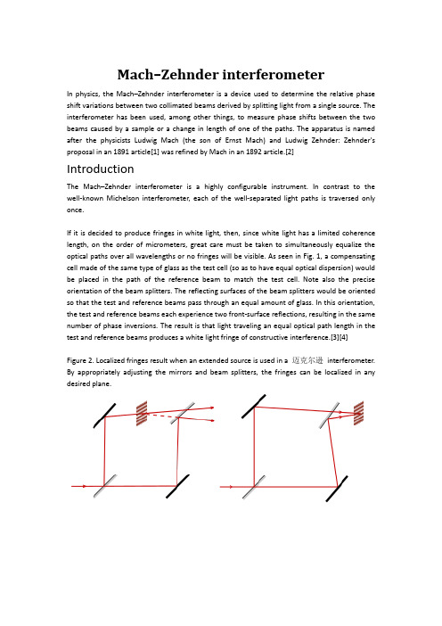
Mach–Zehnder interferometerIn physics, the Mach–Zehnder interferometer is a device used to determine the relative phase shift variations between two collimated beams derived by splitting light from a single source. The interferometer has been used, among other things, to measure phase shifts between the two beams caused by a sample or a change in length of one of the paths. The apparatus is named after the physicists Ludwig Mach (the son of Ernst Mach) and Ludwig Zehnder: Zehnder's proposal in an 1891 article[1] was refined by Mach in an 1892 article.[2]IntroductionThe Mach–Zehnder interferometer is a highly configurable instrument. In contrast to the well-known Michelson interferometer, each of the well-separated light paths is traversed only once.If it is decided to produce fringes in white light, then, since white light has a limited coherence length, on the order of micrometers, great care must be taken to simultaneously equalize the optical paths over all wavelengths or no fringes will be visible. As seen in Fig. 1, a compensating cell made of the same type of glass as the test cell (so as to have equal optical dispersion) would be placed in the path of the reference beam to match the test cell. Note also the precise orientation of the beam splitters. The reflecting surfaces of the beam splitters would be oriented so that the test and reference beams pass through an equal amount of glass. In this orientation, the test and reference beams each experience two front-surface reflections, resulting in the same number of phase inversions. The result is that light traveling an equal optical path length in the test and reference beams produces a white light fringe of constructive interference.[3][4]Figure 2. Localized fringes result when an extended source is used in a 迈克尔逊interferometer. By appropriately adjusting the mirrors and beam splitters, the fringes can be localized in any desired plane.Collimated sources result in a nonlocalized fringe pattern. Localized fringes result when an extended source is used. In Fig. 2, we see that the fringes can be adjusted so that they are localized in any desired plane.[5]:18 In most cases, the fringes would be adjusted to lie in the same plane as the test object, so that fringes and test object can be photographed together.The Mach–Zehnder interferometer's relatively large and freely accessible working space, and its flexibility in locating the fringes has made it the interferometer of choice for visualizing flow in wind tunnels[6][7] and for flow visualization studies in general. It is frequently used in the fields of aerodynamics, plasma physics and heat transfer to measure pressure, density, and temperature changes in gases.[5]:18,93–95Mach–Zehnder interferometers are used in electro-optic modulators, electronic devices used in various fibre-optic communications applications. 迈克尔逊modulators are incorporated in monolithic integrated circuits and offer well-behaved, high-bandwidth electro-optic amplitude and phase responses over a multiple GHz frequency range.Mach–Zehnder interferometers are also used to study one of the most counterintuitive predictions of quantum mechanics, the phenomenon known as quantum entanglement.[8][9]The possibility to easily control the features of the light in the reference channel without disturbing the light in the object channel popularized the Mach–Zehnder configuration in holographic interferometry. In particular, optical heterodyne detection with an off-axis, frequency-shifted reference beam ensures good experimental conditions for shot-noise limited holography with video-rate cameras,[10] vibrometry,[11] and laser Doppler imaging of blood flow.[12]How it worksSet-upA collimated beam is split by a half-silvered mirror. The two resulting beams (the "sample beam" and the "reference beam") are each reflected by a mirror. The two beams then pass a second half-silvered mirror and enter two detectors.PropertiesThe Fresnel equations for reflection and transmission of a wave at a dielectric imply that there is a phase change for a reflection when a wave reflects off a change from low to high refractive index but not when it reflects off a change from high to low.A 180 degree phase shift occurs upon reflection from the front of a mirror, since the medium behind the mirror (glass) has a higher refractive index than the medium the light is traveling in (air). No phase shift accompanies a rear surface reflection, since the medium behind the mirror (air) has a lower refractive index than the medium the light is traveling in (glass).Figure 3.Effect of a sample on the phase of the output beams in a Mach–Zehnder interferometer. The speed of light is slower in media with an index of refraction greater than that of a vacuum, which is 1. Specifically, its speed is: v = c/n, where c is the speed of light in vacuum and n is the index of refraction. This causes a phase shift increase proportional to (n − 1) × length traveled. If k is the constant phase shift incurred by passing through a glass plate on which a mirror resides, a total of 2k phase shift occurs when reflecting off the rear of a mirror. This is because light traveling toward the rear of a mirror will enter the glass plate, incurring k phase shift, and then reflect off the mirror with no additional phase shift since only air is now behind the mirror, and travel again back through the glass plate incurring an additional k phase shift.The rule about phase shifts applies to beamsplitters constructed with a dielectric coating, and must be modified if a metallic coating is used, or when different polarizations are taken into account. Also, in real interferometers, the thicknesses of the beamsplitters may differ, and the path lengths are not necessarily equal. Regardless, in the absence of absorption, conservation of energy guarantees that the two paths must differ by a half wavelength phase shift. Also note thatbeamsplitters that are not 50/50 are frequently employed to improve the interferometer's performance in certain types of measurement.[3]Observing the effect of a sampleIn Fig. 3, in the absence of a sample, both the sample beam SB and the reference beam RB will arrive in phase at detector 1, yielding constructive interference. Both SB and RB will have undergone a phase shift of (1×wavelength + k) due to two front-surface reflections and one transmission through a glass plate.At detector 2, in the absence of a sample, the sample beam and reference beam will arrive with a phase difference of half a wavelength, yielding complete destructive interference. The RB arriving at detector 2 will have undergone a phase shift of (0.5×wavelength + 2k) due to one front-surface reflection and two transmissions. The SB arriving at detector 2 will have undergone a (1×wavelength + 2k) phase shift due to two front-surface reflections and one rear-surface reflection. Therefore, when there is no sample, only detector 1 receives light.If a sample is placed in the path of the sample beam, the intensities of the beams entering the two detectors will change, allowing the calculation of the phase shift caused by the sample.ApplicationsThe versatility of the Mach–Zehnder configuration has led to its being used in a wide range of fundamental research topics in quantum mechanics, including studies on counterfactual definiteness, quantum entanglement, quantum computation, quantum cryptography, quantum logic, Elitzur-Vaidman bomb tester, the quantum eraser experiment, the quantum Zeno effect, and neutron diffraction. In optical telecommunications it is used as an electro-optic modulator for phase as well as amplitude modulation of light.迈克尔逊干涉仪在物理学中,迈克尔逊干涉仪是用于确定通过分离来自单个光源的光而得到的两个准直光束之间的相对相移变化的装置。
光学通信英语作文模板范文
光学通信英语作文模板范文Optical Communication。
With the rapid development of technology, optical communication has become an essential part of our daily lives. It has revolutionized the way we communicate, providing faster, more reliable, and secure transmission of information. In this article, we will explore the basics of optical communication, its advantages, and its applications in various fields.First and foremost, let's understand what optical communication is. Optical communication is a method of transmitting information using light as the carrier. It involves the use of optical fibers, which are thin, flexible, and transparent fibers made of glass or plastic. These fibers are capable of transmitting large amounts of data over long distances at high speeds. The process of optical communication involves converting electrical signals into optical signals, transmitting these signalsthrough the optical fibers, and then converting them back into electrical signals at the receiving end.One of the key advantages of optical communication is its high bandwidth. Optical fibers have a much larger bandwidth compared to traditional copper wires, allowing them to transmit a greater amount of data in a shorter amount of time. This makes optical communication ideal for applications that require high-speed data transmission, such as internet connections, telecommunication networks, and data centers.Another advantage of optical communication is its low signal loss. Optical fibers have the ability to transmit signals over long distances with minimal loss of signal strength. This is due to the fact that light travels through the fibers in a straight line, without being affected by external interference or environmental factors. As a result, optical communication offers a more reliable and stable transmission of information compared to other communication methods.Furthermore, optical communication is also highly secure. Since light signals are transmitted through the fibers, they are not susceptible to electromagnetic interference or eavesdropping. This makes optical communication an ideal choice for transmitting sensitiveand confidential information, such as financial transactions, government communications, and military operations.The applications of optical communication are vast and diverse. In the field of telecommunications, optical communication is used to transmit voice, data, and video signals over long distances, providing high-speed internet connections, cable television, and telephone services to consumers and businesses. In addition, optical communication is also used in the healthcare industry for medical imaging, diagnostics, and remote patient monitoring. It is also widely used in the transportation industry for traffic management, vehicle tracking, and navigation systems.Moreover, optical communication plays a crucial role inthe field of scientific research and education. It is used in laboratories and research facilities for the transmission of data from scientific instruments, such as telescopes, microscopes, and particle accelerators. In addition, optical communication is used in educational institutions for distance learning, online courses, and virtual classrooms.In conclusion, optical communication has revolutionized the way we transmit information, offering faster, more reliable, and secure communication methods. Its high bandwidth, low signal loss, and security make it an ideal choice for a wide range of applications in various fields. As technology continues to advance, the potential for optical communication to further improve and expand its capabilities is limitless. It is clear that optical communication will continue to play a vital role in shaping the future of communication and technology.。
光信息 光电 专业英语词汇
A M light 振幅调制光,调幅光A-frameA 形架a.c. circuit 交流电路a.c. discharge 交流放电a.f. oscillator 声频振荡器A/D conversion 模拟-数字转换A/D Converter 类比数位讯号转换器abac 算图,列线图abampere 电磁系电流单位abaxial 轴外的,离轴的Abb'e Condenser 阿贝聚光器Abb'e constant 阿贝常数Abb'e Illumination 阿贝照明Abb'e Porro 阿贝坡若Abb'e Prism 阿贝棱镜Abb'e Refractometer 阿贝折射计Abb'e Sine Condition 阿贝正弦条件Abbe apertometer 阿贝〔数值〕孔径计Abbe condenser 阿贝聚光镜Abbe constant 阿贝常数Abbe double-diffraction principle 阿贝双衍射原理Abbe eyepiece 阿贝目镜Abbe illuminator 阿贝照明器Abbe invariant 阿贝不变量Abbe number 阿贝数,色散系数Abbe photometric law 阿贝光度定律Abbe prism 阿贝棱镜Abbe refractometer 阿贝折射计Abbe resolution criterion 阿贝分办率判断Abbe treatment 阿贝处理Abbe's formula 阿贝公式Abbe's number 阿贝数Abbe's principle 阿贝原理Abbe's sine condition 阿贝正弦条件Abbe's sine rule 阿贝正弦定则Abbe's theory of image formation 阿贝成像理论Abbe-Konig prism 阿贝-柯尼希棱镜Abbe-type vertical metroscope 阿贝型立式测长义aberrated lens system 有像差透镜系统aberrated optics 有像差光学系统aberrating medium 致〔像〕差媒质Aberration 像差aberration balancing 像差平衡aberration blur circle 像差模糊图aberration constant 光行差常数,光行差恒量aberration correction 像差校正aberration curve 像差曲线aberration figure 像差斑,像差图形aberration function 像差函数aberration haze 像差光雾aberration of reconstructed wave 重建波〔的〕像差aberration residuals 残余像差Aberration Sensor 像差感应器aberration-free system 无像差系统aberrationless 无像差的ablation (1)冲蚀,烧蚀,消融(2)切除ablative flashlamp 消融闪光灯,烧蚀闪光灯ablative recording 〔光〕冲蚀记录Ablative Wall Flashlamp 闪光壁灯,剥壁闪光灯Abney level 阿布尼水准器Abney mounting for concave grating 阿布饰凹面光栅装置abnormal 反常,异常abnormal dispersion glass 反常色散玻离abnormal glow discharge 反常辉光放电abnormal refraction 反常折射above-critical state 超临界〔状〕态above-threshold operation method 超阈值运转法(激光器)abradant 磨料abrade 磨蚀,擦伤abrased glass 磨砂玻离,毛玻璃abrasion 磨蚀Abrasion Maarks 磨耗纹abrasion resistance 磨蚀阻力Abrasive 磨料abrasive disk (1)研磨盘(2)砂轮abrasive fog 磨擦灰雾abrasive grit 磨料粒度abrasive hardness 研磨硬度,耐磨硬度abrasive material 研磨材料abrasive powder 研磨粉abrasive slurry of corundum 金钢砂磨剂abrasive wear 磨蚀,磨损abrideged monochromator 滤色单色仪Abridged Spectrophotometer 筒缩分光光度计abrupt 突变、陡变abrupt contrast border 突变衬比界,陡变友差界abrupt junction 突变结,阶跃结abruption (1)隔断(2)断裂abscissa 横坐标absentee layer 虚设层absest 石棉asbestos 石棉asbestus 石棉absolute atmosphere 绝对大气压absolute black body 绝对黑体absolute brightness 绝对亮度absolute calibration 绝对校准Absolute Coordinate 绝对坐标absolute detector response 检测器绝对响应〔值〕absolute deviation 绝对偏差absolute error 绝对误差absolute index of refraction 绝对折射率absolute luminance threshold (1)绝对〔光〕亮度阈(2)绝对发光率阈Absolute Luminance Thresshold 绝对照明底限absolute measurement 绝对测量absolute optical frequency measurement 绝对光频测量absolute optimal function 绝对最佳函数absolute parallax 绝对相位Absolute Purity Thresshold 绝对纯度底限Absolute Refractive Index 绝对折射率absolute sensitivity 绝对灵敏度Absolute Signal Delay 绝对信号延时absolute stability (1)绝对稳定性(2)绝对稳定度absolute temperature 绝对温度Absolute Temperature Scale 绝对温标Absolute Threshold 绝对界限absolute unite 绝对单位absolute value 绝对值Absolute Vector 绝对矢量absolute zero 绝对零度absorb (1)吸收(2)减震absorbability 可吸收性absorbable 可吸收〔的〕Absorbable implant (scleral buckling method)可吸收之植入物(巩膜扣环法) Absorbance 吸收率absorbance index (1)吸收性(2)吸收率absorbancy 吸光率,吸光本领absorbed layer 被吸收层absorbed power 被吸收率absorbent (1)吸收质(2)吸收体absorber (1)吸收器(2)吸收体(3)减震器absorbing apodisation screen 吸收切趾屏absorbing crystal 吸收晶体absorbing inclusion 吸收掺杂absorbing medium 吸收媒质absorbing phase strip 吸收相位遮板absorbing power 吸收本领absorbing sheet 吸收片absorbing unidimensional apodisator 吸收单维切趾器Absorbing Wedge 吸收光劈Absorptance 吸收比absorptiometer (1)液体吸收气计(2)吸收比色计absorptiometry 吸收测量学Absorption 吸收absorption hologram 吸收全息图Absorption Attenuator 选择性吸收Absorption Band 吸收光带absorption capacity 吸收本领Absorption Cell 吸收匣absorption characteristic 吸收特性Absorption Ciefficient 吸收系数absorption coefficient 吸收系数absorption colour 吸收色absorption control 吸收控制Absorption Curve 吸收曲线Absorption Discontinuity 间歇吸收absorption dynamometer 吸收功率计absorption edge 吸收限absorption effect 吸收效应absorption factor 吸收因数Absorption Frequency Meter 吸收性频率计Absorption Index 吸收指数Absorption Indication 吸收指示剂Absorption Lens 吸收透镜absorption level (1)吸收能级(2)吸收率absorption limit 吸收限Absorption Line 吸收谱线Absorption Loss 吸收损失absorption mean free path 吸引平均自由〔路〕程absorption notch 吸收凹陷Absorption of Radiation 吸收调制Absorption Peak 辐射吸收absorption rate 吸收率Absorption Selective 吸收光谱学Absorption Spectroscopy 吸收锋absorption spectrum 吸收〔光〕谱absorption wave-meter 吸收式波长计absorption-dip (1)吸收〔引起的〕倾斜(2)吸收〔引起的〕凹陷absorption-free materiall 无吸收材料absorptive 吸收的absorptive lens 吸收透镜absorptive power 吸收本领absorptive-type modulator 吸收型调制器Absorptivety 吸收率Absorptivie Attenuator 吸收衰减器absorptivity (1)吸收性,吸收能力(2)吸收率abstract code 抽像代码abundance (1)丰度(2)分布量abunits (e.m.u.)〔c.g.s〕电磁系单位abut (abutment)(1)支座,支架(2)邻接abvolt 〔c.g.s〕电磁系电势单位,绝对伏特(108伏特)AC-powered magnet 交流电力式磁铁AC-powered photostimulator 交流式光刺激器AC-powered slitlamp biomicroscope 交流电力式细隙灯accelerated phosphorescence 加速发磷光accelerating electrode 加速电极accelerating lens 加速〔电子〕透镜accelerating potential 加速〔电〕势差,加速〔电〕位差Accelerating Voltage 加速电压Acceleration Space 加速空间accelerator (1)加速器(2)〔显影〕促进剂accelerograph 自动加速度记录仪Accentuated Contrast 加动对反差accentuation (1)加重(2)频率校正(3)对比accentuator (1)加重器(2)频率效正电路Acceptance Angle 接受角Acceptance Angle Plotter 接受角绘图器Acceptance Cone 接受锥体acceptance gauge 验收规Acceptance Pattern 接受图Acceptor 受体acceptor density 受主浓度acceptor impurity 受主杂质acceptor impurity level 受主杂质能级acceptor level 受主〔能〕级acceptor site 受主〔能〕级access (1)入口通路(2)取数(3)存取(泛指取数或存数)Access Coupler 出入偶合器access time 存取时间,取数时间access width 存取位数accessory 零任,附件,附属设备accidental degeneracy 随机简并度accidental error 偶然误差Accommodation 调节,适应Accommodation Limits 调节极限accommodometer 眼调节计Accomulator 蓄信器accumulation (1)累积,积蓄(2)存储accumulation point 聚集点accumulative error 累积误差accumulator (1)存储器(2)蓄电池(3)累积器accumulator register 累加寄存器accuracy (1)准确(2)准确度accuracy grade 准确度等级accuracy of test glass 玻璃样板准确度acetate base 醋纤片基acetate cellulose butyrate 醋酸纤维丁酯Acetate Film 醋酸膜acetic 醋的acetic acid 醋酸acetone 丙酮acetonitrile 乙青acetophenone photoreduction 乙洗苯苯光致还原acetyl cellulose 乙洗纤维素acetylene (1)乙炔,电石气(2)双亚乙基achloropsia 绿色盲achromat 消色差透镜,消色差镜头achromate 色盲Achromatic 消色差的achromatic coating 消色差镀膜Achromatic Color 消色色彩achromatic colour 无彩色achromatic condenser 消色差聚光镜achromatic coronagraph 消色差日冕仪achromatic doublet 消色差双合透镜achromatic fringe 消色差条纹achromatic image 消色差块achromatic lens 消色差透镜Achromatic Lens, Achromat 消色差透镜achromatic light 白光,消色差光,无彩〔色〕光achromatic micro objective 消色差显微物镜achromatic objective 消色差物镜Achromatic Point 消色点achromatic prism 消色差棱镜achromatic quarter waveplate 消色差四分之一波片achromatic telescope 消色差望远镜achromatic triplet 消色差三合〔透〕镜achromatic wedge 消色差光劈,消色差光楔Achromatism 消色差性achromatizarion 消色差achromatized 〔已〕消色差〔的〕achromatopsia 全色盲acicular 针状的acicular crystal 针状晶体acid 酸、酸性的acid development 酸显影acid proof 耐酸的acid wash 酸洗的acid-free 无酸的acidic solution 酸溶液acidity (1)酸性(2)酸度acme thread 梯型螺纹Acolight 音灯acoustic beam deflector 声束偏转器acoustic branch 声频支acoustic coupler 声音藕合器;音效藕合器Acoustic Delay Line 声延迟线acoustic diffraction grating 声衍射栅acoustic dispersion 声频散acoustic emission wave 声发射波acoustic field 声场acoustic hologram 声全息图acoustic holographic system 声全息系统acoustic holography 声全息术acoustic image 声像acoustic imaging 声成像Acoustic Impedance 声阻抗Acoustic Interferometer 声干涉仪acoustic microscopy 声显微术Acoustic Radiation Pressure 声发射压力acoustic signal 声频信号Acoustic Surface Wave 声表面波acoustic surface wave (ASW)声面波acoustic to optical image converter 声光像转换器Acoustic Wave Filter 声波滤器acoustic wave propagation 声波传播Acoustical Conduction 声导acoustical hologram 声波全像体Acoustical Holography 声波全像术Acoustical Units 声学单位acoustics (1)声学(2)音质Acousto Photorefractive Effect 声光折射效应acousto-optic 声光的acousto-optic beam positioning 声光束定位acousto-optic Bragg-diffraction 声光布喇格衍射acousto-optic cavity 声光腔acousto-optic cell 声光调制器,声光盒Acousto-Optic Deflection 声光偏转,声光偏差Acousto-Optic Deflector 声光致偏器Acousto-Optic Diffraction 声光绕射acousto-optic effect 声光效应acousto-optic filter 声光滤波器acousto-optic interaction 声光相互作用acousto-optic laser 声光激光器acousto-optic light deflector 声光偏转器acousto-optic materiall 声光材料acousto-optic mode-locker frequency doubler 声光锁模倍频器Acousto-Optic Modulation 声光调制acousto-optic modulator 声光调制器acousto-optic Q-switching 声光Q开关acousto-optic scanner 声光扫瞄器Acousto-Optic Shutters 声光快门acousto-optically tuned laser 声光调谐激光器acousto-photorefractive effect 声光折射效应Acoustooptic Effect 声光效应acoustooptics 声光学acquiring (1)探测(2)照准(3)瞄准acquisition (1)探测,发现(2)捕获、拦截(3)目标显示acquisition equipment 捕获装置actice illumination (1)有源照明(2)主动照明Actinic 光化(性)的actinic absorption 光化吸收actinic achromatism 光化消色差〔性〕Actinic Focus 光化焦点Actinic Glass 光化玻璃Actinic Radiation 光化辐射actinicity (1)光化性(2)光化度actinides 铜类元素Actinism 光化学actinium (Ac)锕actinochemistry 露光化学actinography (1)光能测定仪(2)辐射仪actinology (1)光化学(2)射线化学Actinometer 露光计actinometry 光能测定术,曝光测定术、光作用测定术actinomorphic 辐射对称的actinotherapy 射线疗法,放射疗法action (1)作用(2)主动力(3)作用量action photography 动态摄影action radius 作用半径,有效距离action spectrum 作用光谱activate (1)激活、活化(2)起动,触发activated carbon 活性碳activated carrier (1)激活载流子(2)激活载体activated silicate glass 激活的硅酸盐玻璃activated state 激活态,活化态activated switch 起动开关activating agent 激化剂,活化剂activation (1)激活、活化(2)激发activation center 激活中心activation energy 激活能activation fiber (1)激栝纤维(2)主动纤维activation of filament 灯丝的激活activation of homing 进入自动寻的制导状态,接通归航装置Activator 活化计activator atom 激活原子active (1)主动(2)有效的(3)有源的(4)激活的active area 有效面积active atom 激活原子active autofocusing 有效自聚集active caity 激活腔active carbon 活性碳active current 有功电流Active Device 有源器件active element 有源元件active fibre 激活〔光学〕纤维active figure control 有效图像控制active imaging system 主动成像系统active impurity 活性杂质Active Infrared System 活动红外线系统active infrared tracking system 主动式红外跟踪系统active interferometer 有源干涉仪active ion 激活离子Active Layer 放射层active level 激活能级active material 激活材料,放射材料Active Medium 活性介质active mode-locking 主动锁模active network 有源网路Active Optical Fiber 激活光纤Active Optics 主动光件active oxygen 活性氧active power 有功功率active pulse interferometer 主动脉冲干涉仪Active Region 放射区active resonator 有源共振器active-device 有源器件actively mode-locked Nd glass laser 主动锁模钕玻离激光器Activity 放射性活度,活性activity coefficient 激活系数acton (An)锕射气actual image point 实际像点actual temperature 真实温度actuate 作用,开动actuating motor 伺服电动机actuating signal 作用信号actuation (1)激励(2)起动,传动actuator (1)执行机构、执行元件(2)传运机构(3)激励器acuity 锐度,敏度acuity for defocus 散焦锐度Acuity, Visual 视觉敏锐度Acutance 锐度acute angle 锐角Acute Bisectrix 敏锐二等分角acute exposure 短时间强照射acute irradiation 急性辐射acuteness 锐度adamantine spar 刚玉adaptability 适应性,适用性Adaptation 视觉调整adapter (1)转接器(2)接合器(3)适配器adapter lens 接合器透镜adapter sleeve 紧定套,接头套〔筒〕,连接套管adaption 自适应,配合,匹配adaption brightness 自适应亮度adaption level 自适应能级adaptive control 自适应控制adaptive filter 自适应滤光片adaptive laser resonator 自适应激光共振器adaptive optical system 自适应光学系统Adaptive Optics 调适形光件Adaptometer 视觉调整计Adaptometer (biophotometer)眼适应时间计adaxial 向轴的,近轴的add 加,附加addend (1)加数(2)附加物addendum (1)齿顶,齿顶高(2)附录addendum angle (1)齿顶角(伞齿轮的)addendum circle 齿顶圆adder (1)加法器,相加器(2)加法电路adder-subtractor 加减器addition (1)加,加法(2)附加,补充addition of diffraction patterns 衍射图形叠加addition of modes 模叠加addition of optical fields 光学场叠加addition of wavefronts 波阵面叠加,波前叠加additional mirror 附加镜additional wave 相加波,附加波additive 添加物添加剂additive channel 可加信道Additive Color Mixing 光彩混合Additive Color Process 增色处理additive colour 加色additive complementary colors 〔加色混色的〕补色additive filter 附加滤光片additive mixture of colours 加色混合additive noise 相加噪声additive primaries 加色混合的原色additive process 加色法additivity 相加性,叠加性Additivity of Luminance 亮度叠加Address 资料储位address hologram 地址全息图address read wire 地址读出线address write wire 地址写入线Addressability 安排资料储位的能力Addressability Measure 可寻址量度addressable 可寻址的addressable memory 可寻址存储器Addressable Point 可寻址点addressable register 可寻址寄存器,可编址寄存器addressing 寻址adele 赋值矢量adherence 附着〔力〕adhesion (1)附着,粘附(2)附着力,粘附力adhesive (1)附着的(2)粘附度adhesive power 附着力Adhesives 附着剂adiabatic 绝热的adiabatic approximation 绝热近似〔法〕adiabatic demagnetization 绝热热磁adiabatic ionization energy 绝热电离能量Adiabatic Laser Colorimetry 绝对雷射色度学adiabatic polarization procedure 绝热极化处理Adiabatic Process 绝热过程adiabatics 绝热曲线adiactinic 绝射的,不透光的adiathermanous 绝热的,不透红外线的adjacency 邻接adjacency effect 邻〔接〕效应adjacent agle 邻角adjacent resonance 相邻信道共振adjacent wave 邻波adjoint 伴〔随〕adjustable 可调节的,可调整的,可校准的adjustable angle square 活动角尺adjustable bearing 可调轴承adjustable bench level 可调台式水准仪adjustable cup mount 可调杯形座adjustable guide bar 可调导杆adjustable lever 调节杆adjustable micrometer 可调千分尺adjustable slit 可调〔狭〕缝adjustable wrench 活络板头adjuster (1)调节器(2)调准装置adjusting bracket 调节架adjusting screw 调节螺丝adjustment 调准,配准adjustment range 调整范围Adjustment, Interpupillary 目眼中心距调整admeasure 测量,测定admeasuring apparatus 测像仪admission 放入,接纳,进气admittance (1)光纳(2)导纳admittance matching (1)光纳匹配(2)导纳匹配admixture (1)掺质,混合(2)混合物ADP 二氢磷酸氨adsorbability 吸附能力adsorbed film 吸附膜adsorbed layer 吸附层adsorbent 吸附剂adsorption 吸附〔作用〕,表面吸收adsorption chromatography 吸附色谱〔法〕adsorption effect 吸附效应adsorption isotherm 吸附等温线adsorption spectrometer 吸附分光计adulterated (1)掺杂的,掺假的(2)低劣的advance in path 光程提前量advanced camera 高级照相机Advanced Research Projects Agency 远景研究计划局部(美国) advancer 〔相位〕超前补偿器advancing front 前沿advancing wave 前进波advertiser 信号装置,信号器Advisory Committee of the Radioactivity 放射性谘询委员会AE camera 自动曝光照相机aeolight 〔充气冷阴极〕辉光管aeolotropic crystal 各向异性晶体aeolotropism 各向异性aeration 充气,吹风aerial (1)空气的,气体的(2)空中的,航空的aerial array 天线阵Aerial Camera 航空照相机Aerial Film 航空照相软片Aerial Mapping 航空写像aerial object 航空目标,空中物体Aerial Photogrammetry 航空照相测量术aerial photographic survey 航空照相测量Aerial Photography 航空照相Aerial Photoreconnaissance 航空照相勘察aerial radioactivity measurement 航空放射性测量Aerial Reconnaissance 航空勘察Aerial Survey 航空测量aerial tuning 天线调谐aeriscope 超电摄像管,超光电移像管aero-camera 航空照相机aerocartograph 航空测量图,航空测图仪Aerocartography 航测地图aerochronometer 航空精密计时仪aerodynamic flow 气动流aerodynamic heat transfer 气动热传递aerodynamic 〔al〕气体动力〔学〕的,气动的aerograph (1)无线电报机(2)航空气像仪aerographic film 航空摄影胶片aerohypsometer 高空测高计aeromagnetic survey 航空磁测量aeronautics 航空学aeronomy 高层大气物理学aerophotogrammetric mapping instrument 航测制图仪器aerophotogrammetric survey 航空摄影测量aerophotogrammetry 航摄测量术aerophotograph 航空摄影aerophotographic camera 航空摄影机aerophotography 航〔空〕摄〔影〕学,航空照相术aerophysical survey 航空物理测量aeroplane 飞机aeroprojector 航测制图仪aeroscope 尘埃计,空中观测〔细菌灰尘收检〕器aerosimplex 简单投影测图仪Aerosol 气悬体,液悬胶体aerosol droplet 悬浮微粒aerosol inhomogeneity 气悬体不均匀性aerosol measurement 气悬体测量aerosol particle analysis 气悬微粒分析aerosol scattering 气悬散射aerosol single scattering 气悬体单散射aerosol size distribution 气悬体大小分布aerospace 航空空间,宇宙空间aerospace industry 航空空间工业,航天工业aerosphere 〔生理〕大气层aerosurvey 航空测量aerosurveying 航〔空〕摄〔影〕测量术aerotar 航摄镜头aerothermodynamics 空气热力学aerothermoelasticity 空气热弹性理论Aerotriangulation 航空三角测量aerotron 三极管aerovelox 小型投影测图仪aeschynite 易解石aether (1)以太(2)醚aether drift 以太漂移AFC system 自动频率控制系统affine collineation 仿射共线affine transformation 仿射变换affinity (1)类似(2)亲合势(3)仿射性affix (1)添加(2)添加物(3)附标Afocal 无焦点竹afocal attachment lens 附加望远镜头afocal doublet 无焦双透镜afocal imaging system 无焦成像系统afocal lens 无焦透镜afocal zoom telescope 连续变倍望远镜after-current 余电流after-effect 後效After-Image 留像after-schock 余震afterburner 後然室,补燃器Afterglow 余辉afterglow period 余辉期afterimage 余留成像Afterimage flasher 影像後闪光器afterpulsing 跟随脉冲aftertreatment 後处理against moisture 防潮against vibration 防震against-the-rule astigmatism 反常像散agar 琼脂agate 玛瑙age-hardening 时效硬化ageing 时效,老化、陈化ageing oven 老化炉agent 剂Agfacolor 阿克发彩色(商名) agglomerating 烧结aggregate (1)组合〔的〕,集合〔的〕(2)机组aggregate polarization 集合偏振,集偏振化agile missile 灵巧导弹aging 时效,老化,陈化aging of electroluminescence 电致发光老化aging rate 老化率agitation (1)搅拌,搅动(2)激发,激励(3)骚动agitator 搅拌器aglow 灼热〔的〕,发红〔的〕Ahrens polarizing prism 阿伦斯偏振棱镜aid 设备,仪器aiming 瞄准Aiming Circle 方位标定仪aiming device 瞄准装置aiming point 〔测量〕觇点,瞄准点aiming telescope 瞄准望远镜air admittance valve 进气阀air agitation 空气扰动Air Bearing 空气承轴air blast (1)气喷净法(2)喷气(3)喷气器air breathing laser (ABL)吸气式激光器,气动光器air bubble 气泡air chuck 气动卡盘air cleaner 空气调节器air damping 空气阻尼Air Dose 辐射剂量air filter 空过滤器air gap 空气隙air gauge 气动量规air knife coating 气刀涂胶法air level 〔气泡〕水准仪air light (1)〔空气中〕散射光(2)航空信号埃air micrometer 气动测微计air photogrammetric survey 航〔空〕摄〔影〕测量air pollution measurement with lidar 激光〔雷达〕测大气污染air pollution monitoring 空气污染临测air pressure gauge 气压计air purge 空气纯化air reconnaissance camera 航空侦察照相机air seal 气封air support bag 空气承囊(气胎)air transportable sonar 机械声纳air vent 通风管,通风孔,排气口air 〔borne〕surveying 航空测量,航测air-bag support system 空气囊支撑系统air-conditioning system 空〔气〕调〔节〕装置air-cored 空心的,无铁心的air-defence sighting telescope 防空观测望远镜air-filled thermocouple 充气温差电偶air-glass reflection 空-玻璃界面反射air-glass surface 空气-玻璃界面air-in 送气,充气air-locked 不透气的,气密的air-map 航空图,空中摄影地图air-operated controller 气动控制气air-out 出气,排气air-pad bag 空气垫囊air-proof 不透气的,密封的air-pump 气泵air-scattered 空气散射air-spaced double anastigmat (Celor) 双分离对称消像散镜头(赛罗镜头) Air-Spaced Doublet 中空双合透镜air-survey camera 航测照相机air-to-air identification 空对空识别air-to-air intercept 空对空拦截air-to-air laser ranging 空对空激光测距air-to-ground laser rangefinder 空对地激光测距离air-to-ground laser ranging 空对地激光测距Air-to-Ground Phototransmission Systems 空对地照片传递系统airborne 机载的,航空的airborne electromagnetic survey 航空电磁勘探airborne gaseous laser 机载气体激光器airborne gravity survey 航空重力测量airborne ir imaging 机载红外成像airborne ir transmissometer 机载红外透射仪airborne laser radar 机载激光雷达airborne laser rangefinder 机载激光测距仪airborne laser ranger 机载激光测距仪airborne laser tracker (ALT)机载激光跟踪器airborne oceanographic lidar system 机载海洋激光雷达系统airborne radioactivity survey 航空放射性测量airborne remote sensing system 机载遥感系统airborne television system 机载电影系统airbrake 空气制动器,减速板airbrush 气笔,喷枪aircraft landing lamp 飞机着落信标灯Airglow 夜光,气辉airglow emission 辉光放射airglow intensity 大气辉光强度airing (1)通气(2)充气(3)起泡沫airload 气动负载airphoto (1)航空摄影(2)航摄相片airscoop 进气口,进气道airspace (1)空城(2)空隙airtightness 气密〔封〕性airway (1)航路(2)通气孔airy (1)空气的(2)通风的Airy Differential Equation 爱礼微分方程式Airy diffraction disc 爱里衍射斑Airy diffraction integral 爱里衍射积分Airy diffraction pattern 爱里衍射图样Airy disc 爱里〔衍射〕Airy Disk 爱礼圆盘图Airy disk radius 爱里斑半径Airy point 爱里〔支援〕点Airy system 爱里系统Airy type objective 爱里型物镜aisle 通道,走廊Al-clad 用铝作覆盖层的alabamine (At)砹alarm (1)警报(2)警报器alarm lamp 信号灯Albada finder 阿尔巴达寻像器,阿尔巴达瞄准器Albedo 反照率albedo radiation (1)反照率辐射(2)辐射反射率albedometer 反照率计alcohol 酒精,乙醇aldehyde 乙醛alexanderson altimeter 反射高度计,回波测高计Alexandrite 翠绿宝石algebra of matrices 〔矩〕阵代数algebraic complement 代数余子式algebraic expression 代数〔表达〕式Algerithm 演算algorithm 算法algorithmic language 算法语言aliaing version 重叠变形alias-type transformation 图像固定坐标移动之变换Aliasing 假像aliasing error (1)混淆误差(2)重叠误差alibi-type transformation 坐标固定图像移动之变换Alidade 旋标装置,准照仪alidade protractor 照准仪量角器alienation coefficient 不相关系数,相疏系数align (1)列成一行(2)瞄准目标(3)对准,校直(4)定位,定中心Aligned-Cup Method 钟罩互夹定心法aligner 准直器,校准器Aligning 较轴作业Aligning Chuck 镜片对心座Aligning Components of Prism Assemblies 棱镜定位法aligning interferometer 校直干涉仪alignment (1)校直(2)对准(3)排列alignment axicon 校直轴锥镜alignment bracket 校直轴支架Alignment Bundle 校准纤维束alignment by sight 目测准直法alignment chart 列线图alignment diagram 列线图,算图alignment dock 校直坞alignment error 校直误差,调准误差Alignment Laser 校直雷射,校准用雷射alignment of crystal 晶体排列alignment sphere 调准球alignment target 对准目标Alignment Telescope 校直望远镜,校准用望远镜alignment-telescope bracket 校直望远镜托架alive (1)活的(2)通电流的,加电压的alive circuit 带电线路alkali 〔强〕碱alkali earth metal 碱土金属alkali halide 卤化碱alkali metal 碱金属alkali-antimonides 碱金属锑化物alkali-containing glass 含碱玻璃alkali-dimer 碱二聚物alkali-halide crystal 卤化碱晶体alkali-rich glass (crown)纯碱玻璃(冕牌玻璃)alkaline (1)碱性(2)碱的alkaline earth fluoride 碱土氟化物alkaline earth metal 碱土金属alkaline high energy battery 碱性高能电池组alkaline metal 碱金属alkaline treatment 碱产处理alkalinity (1)碱性(2)碱度alkyl iodide 烷基碘All Optical Communication 全光通信all-dielectric multilayers 多层全介电膜all-metal 全金属all-pass filter 全通滤波器all-purpose computer 通用计算机all-purpose instrument 通用仪器all-purpose telescope 通用望远镜all-supersonic 纯超声速的all-transistor camera 全晶体管照相机all-weather (1)全天候的(2)耐风雨的allegiance (1)结合,耦合(2)通信,联系(3)键allied Fourier integral 同源传里叶积分alligation 合法,混合法allochroic 变色的,非本色的allochromatic 义质色的allochromatic colour 义质色allochromatic crystal (1)义质光导性晶体(2)义质色晶体allochromatic photoconductor 义质色光电导体allochromatism 掺质色性Allochrometic 杂质色的Allogyric Birefringence 异旋双折射allomorph 同质异晶allomorphism 同质异晶体allotment 配置,分配、分配额allotriomorphic crystal 不整形晶体allotrope 同素异形性allotropic transformation 同素异形变化allotropism 同素异形性allotropy 同素异形allotter 分配器allowable deviation 容许偏差,许用偏差allowable error 容许误差allowable exposure 容许照射,容许曝光allowable stress 容许胁强,容许应力allowable transition 容许跃迁allowance (1)容限,公差(2)加工余量allowed band 容许带,公差带allowed spectrum 容许谱allowed spectrum shape 容许能谱形状alloy 合金alloy steel 合金钢,特殊钢alloy-junction 合金结Alloy-Junction Photocell 具合金接头之光电池alloy-junction transistor 合金结晶体管allyl diglycol carbonate 烯丙基双甘油碳酸盐alnico 铝镍钴aloxite (Al2O3) (1)熔融氧化铝(人造刚玉磨料)(2)铝砂alpax 铝硅合金alpha meterα 射线〔强度〕测量计alpha rayα 射线alpha-crystalα 晶体alpha-ray spectrographα 射线摄谱仪alpha-ray spectrometerα 射线光谱仪alpha-ray spectrumα 射线谱alphabet laser 多掺激光器alphanumeric 字母体字的Alphanumeric Reader 文数字阅读机alphatronα 电离真空计,α粒子电离压力计alsimag 铝硅镁合金(一种高频绝缘材料)alt-alt telescope mounting 卧轴–卧轴型望远镜安装结构alt-azimuth (1)地平经纬仪(2)地平〔式〕装置alt-azimuth telescope mounting 卧轴–竖轴型望远镜安装结构Altazimuth 望远镜头调整器alternate matrix 交错〔矩〕阵alternate partial polarizer filter 交变部分偏振滤光器alternate-line scanning 隔行扫瞄alternately dark and bright rings 明暗相间的环alternating current (a.c.)交流电alternating current amplifier 交流放大器alternating current generator 交流发电机alternating current machine 交流机alternating current motor 交流发电机alternating current transformer 交流变压器alternating current tube 交流〔电子〕管alternating displacement 交变位移alternating electromotive force 交变电动势alternating light method 两光交换法alternating motion 往复运动alternating quantity (1)变量,交变量(2)交错量alternating voltage 交流电压alternating-gradient focusing principle 交变陡度聚焦原理alternating-gradient lens 交变陡度透镜alternating-gradient magnetic focusing 交变陡度磁聚焦alternation 交替,变换,交流alternator 交流发电机altimeter 高度计,测高仪altitude (1)地平纬度(2)高度,海拔altitude circle (1)竖直度盘(2)地平经圈altitude gauge 测高计Altman modification 阿特曼改进型〔目录〕altrashort pulse 超短脉冲alum 明矾alum glass 明矾晶alumel 镍铝锰合金(高温热电偶材料)alumina 铝土,矾土alumina borosilicate glass 硼硅酸铝玻璃aluminium (AL)铝aluminium alloy 铝合金aluminium antimonide 锑化铝aluminium arsenide 砷化铝aluminium backing 铝垫片,铝底座aluminium coating 铝膜aluminium foil lamp 铝箔灯aluminium mirror coating 铝反射膜aluminium oxide 氧化铝(Al2O3)aluminium oxide crucible 氧化铝坩埚aluminium paint 铝涂料,铝涂层,铝〔银灰〕漆aluminium-coated Pyrex 镀铝荧光屏aluminium-oxygen group 铝氧族Aluminized Cathode-Ray Tube 镀铝阴极射线管aluminized mirror 镀铝镜Aluminizing 铝化alundum 三氧化二铝(Al2O3),刚铝砂(磨料),铝氧粉Alzac method 电解光辉法(制造铝反射镜的)Alzac reflector 铝制金属反射镜Alzak aluminium 铝制金属友射镜AM Dector 调富检波Am-cw laser ranging 连续波调幅激光测距Am-Pm conversion 调幅–调相变换Am-Pm discriminator 调幅–调相鋻频器amagat 阿马伽(0℃,1大气压下的气体的密度单位。
光学名词中英文对照

incoherence addition interference phenomenon of light coherent condition single photon interference relationship between optical path difference and phase difference wavefront-splitted interference Young's double-slit interference experiment Thomas Young interference pattern (fringe) order of interference nonlocalized interference nonlocalized fringe Fresnel bimirror Fresnel biprism Lloyd mirror visibility wave train coherence time coherence length temporal coherence spatial coherence critical width of light source interference aperture angle partially coherent light amplitude-splitted interference film interference equal-inclination interference equal-inclination fringes localized interference
泰勒判据 象分辨本領 物镜的分辨本領 相对孔径
Taylor criterion image resolving power resolving power of objective relative aperture
迈克尔逊干涉仪测量光波的波长实验报告

迈克尔逊干涉仪测量光波的波长实验报告英文回答:Michaelson Interferometer Experiment for Measuring the Wavelength of Light Waves。
The Michelson interferometer is an optical instrument that uses interference to measure the wavelength of light waves. It was invented by Albert Michelson in 1881, and it is still used today in a variety of applications, such as spectroscopy and laser metrology.The Michelson interferometer consists of two mirrors that are placed at a distance of L from each other. A beam of light is split into two beams, and each beam is reflected by one of the mirrors. The two beams are then recombined, and the interference pattern is observed.The distance between the fringes in the interference pattern is given by the following equation:```。
d = λ/2。
```。
where d is the distance between the fringes, λ is the wavelength of the light, and θ is the angle between thetwo beams.To measure the wavelength of a light wave, theMichelson interferometer is set up so that the two mirrors are parallel to each other. A beam of light is split into two beams, and each beam is reflected by one of the mirrors. The two beams are then recombined, and the interference pattern is observed.The distance between the fringes in the interference pattern is measured, and the wavelength of the light waveis calculated using the equation above.For example, if the distance between the fringes is 0.5 mm, then the wavelength of the light wave is 1 μm.The Michelson interferometer is a very precise instrument, and it can be used to measure the wavelength of light waves with a high degree of accuracy. It is a valuable tool for a variety of applications, such as spectroscopy and laser metrology.中文回答:迈克尔逊干涉仪测量光波波长的实验报告。
迈克尔逊激光干涉仪测量原理(Me...
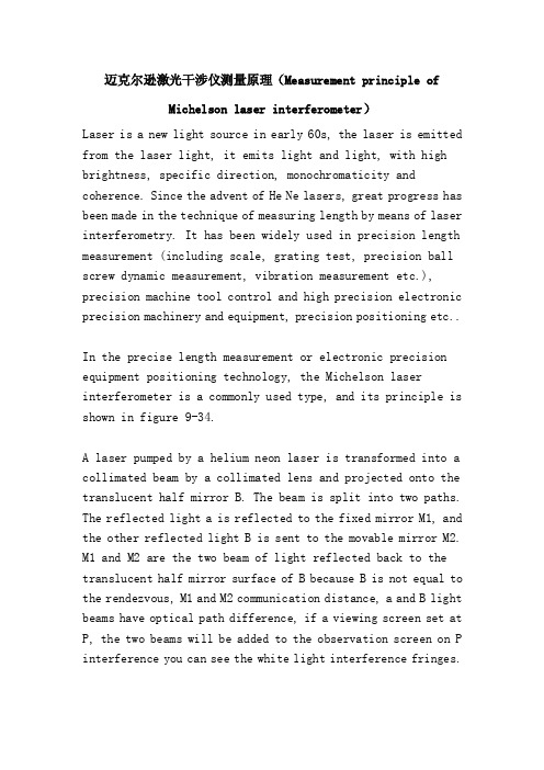
迈克尔逊激光干涉仪测量原理(Measurement principle ofMichelson laser interferometer)Laser is a new light source in early 60s, the laser is emitted from the laser light, it emits light and light, with high brightness, specific direction, monochromaticity and coherence. Since the advent of He Ne lasers, great progress has been made in the technique of measuring length by means of laser interferometry. It has been widely used in precision length measurement (including scale, grating test, precision ball screw dynamic measurement, vibration measurement etc.), precision machine tool control and high precision electronic precision machinery and equipment, precision positioning etc..In the precise length measurement or electronic precision equipment positioning technology, the Michelson laser interferometer is a commonly used type, and its principle is shown in figure 9-34.A laser pumped by a helium neon laser is transformed into a collimated beam by a collimated lens and projected onto the translucent half mirror B. The beam is split into two paths. The reflected light a is reflected to the fixed mirror M1, and the other reflected lightB is sent to the movable mirror M2. M1 and M2 are the two beam of light reflected back to the translucent half mirror surface of B because B is not equal to the rendezvous, M1 and M2 communication distance, a and B light beams have optical path difference, if a viewing screen set at P, the two beams will be added to the observation screen on P interference you can see the white light interference fringes.Two beams interference light meet on the viewing screen at the center of P, the result of interfering light beams, is strengthening or weakening or offset each other each other, by the two beam optical path difference L (equal to the light path decided through the geometric distance and refractive index of the product, the air refractive index is approximately equal to 1). As can be seen from Fig. 9-23, the optical path difference between the two beams of a and B reaches the center of the P center of the observation screenL = 2 (BM2 - BM1) = 2 (Lm-Lc) (9-6)When the optical path difference L is an integer multiple of the laser wavelength lambda, i.e.Delta L = N lambda (N is positive integer) (9-7)The two laser beams reinforce each other, and a bright fringe appears at the center of the P screen.When the optical path difference L is odd times of the laser half wavelength, that is(9-8)The two lasers cancel each other, and dark stripes appear at the center of the P screen.If the moving mirror M2 is moved from L to M 2, the interference fringes of the center of the screen P will change alternately due to the change of the B optical path of the beam. Obviously,when the M2 moves lambda /2 distance, the interference fringes change alternately. If you record the number of alternating changes in N at the center of the screen, then you can measure the distance M2 moves through to M 2, that is, L(9-9)This is the formula for measuring the length of the Michelson laser interferometer.For an actual interferometer, if the medium is air, the upper is rewritten as(9-10)Type L - measured length (m), that is, the moving distance of the moving mirror M2 relative to BN - refractive index of air;N - observe the number of changes in the light and shade of the interference fringes on the screen.In a practical Michelson type laser interferometer length measuring instrument, this is the way of measurement:At the moment T1, the reference mirror (fixed mirror), the M1, and the moving mirror M2 are at the beginning of the measurement, as shown in figure 9-23. At this time, the initial optical path difference is 2 (Lm - Lc), and the corresponding fringe number is(9-11)Type Lm - measuring arm length (mu m);Lc - reference arm length (mu m).At time T2, the measurement is over. The moving mirror M2 moves at the measured length L (or the positioning distance) and is in position. The optical path difference isThe number of fringes corresponding to(9-12)Obviously, N=N2+N1 (9-13)among(9-14)In practical measurement, interference fringe counting method is adopted. At the start of the measurement, the counter is set to zero (N1 = 0), corresponding to the measured length, and the number of interference fringes counted by the counter is N = N2.It is necessary to point out that when the measurement is carried out in the standard strictly, namely n, Lm, Lc and lambda 0, measured the length or length of L positioning completely unchanged in the whole measurement process, usinga formula (9-14) as the basic formula of measurement. However, it is difficult to do so in all practical measurements and must be fully included in the measurement interval (t2-t1) for this purpose. Because of the influence of the change of the above parameters on the measurement results, formula (9-12) is only used as the basic formula of measurement.High precision measurement in the need to comprehensively consider the influence of environmental conditions on the measurement standard deviation (t2-t1), and the change of environmental conditions within the measurement time (including temperature, humidity, air pressure, deformation structures etc.) caused by the change of N, Lm, Lc, lambda 0 and L the parameters of measurement results.。
华中科技大学研究生先进光纤传感课程罗海鹏--OE(2015)多模微纳光纤测T、RI,基于菲涅尔反射-6
光学仪器测量方法:镜面间距检测系统说明书
8th International Conference on Manufacturing Science and Engineering (ICMSE 2018)Design Method of the Measuring System for the Mirror Surface Spacingof a compound lensPing Zhong1,a,Shaohui Pan1,b, Zhisong Li2,c and Xingyu Gao1,d1College of Science, Donghua University, Shanghai 201620, PR China2College of Information Science and Technology, Donghua University, Shanghai 201620, PR China a b*****************,c****************,d*****************Keywords:Optical fiber low coherence interference, lens mirror space, Signal-to-noise ratio, Band-pass filter, least square methodAbstract:Based on the principle of low coherent light interference of optical fiber, a new method for detecting the distance between the mirror surfaces of a compound lens is proposed. Firstly, a system based on the principle of low coherent light interference is designed. Secondly, the frequency calculation method of interference signal of measurement system is put forward, and the band-pass filter is designed for interference signal to improve the signal-to-noise ratios. Based on the characteristics of low coherence light interference signal, the least squares symmetric peak location algorithm is proposed, which realizes the precise locating of the peak of the interferometric signal. Besides, the experiment of measuring the distance between the compound lens is carried out and the measurement error is analyzed.IntroductionIn the manufacture of optical instruments, the center thickness machining precision and assembly precision of the lens have an important influence on the imaging quality of the optical system. Especially in high-performance precision optical systems such as aviation, aerospace and microscope systems, there are strict control requirements for the lens center thickness and the mirror spacing. So, how to get high precision measurement results is a challenging topic. At present, the method for measuring distance between the mirror surfaces of a compound lens is mainly divided into two types, the one is contact measurement and the other is non-contact measurement. The structure of contact measurement is relatively simple, but it has a large defect itself, such as easy to scratch the lens and destroy the lens. The frequent contact between the surfaces of the probe and lens can also make the worn lenses and affect the measurement accuracy. Non-contact measurement system is relatively complex, but it can perform nondestructive testing on the lens group. It is mainly to measure the relative position of the mirror surface by measuring the reflection signal of the lens surface. The methods mainly include image method [1], axial dispersion [2], differential confocal method [3], image calibration method [4, 5], etc. Low-coherence optical interferometry, as the main detection method of non-contact measurement for optical devices, is one of the hotspots today. In this paper, based on the principle of low-coherence light interference, a system for measuring the lens spacing of the compound lens is designed and the main factors affecting the detection accuracy are studied, and the effective method for signal filtering and waveform peak location is proposed.Measurement principle and system design of lens spacingLow-coherence light interferometry [6-12] is an interferometric technique using a broad-spectrum light source as a coherent light source. The coherence length is short and the interference peak can be generated only when the optical path of the measured light and the reference light is equal, so it has a good spatial positioning characteristic. By calculating the distance between the interference peaks at the apex of the front and rear mirror surfaces, the lens group spacing and the center thickness of the lens can be calculated. In this paper, the basic structure of Michelson interferometer is adopted, in which the light emitted the light source is passed through the optical fiber coupler to produce the measured light and the reference light respectively. On the one hand, the reflected signal come from the different surfaces of the sample has a different optical path. On the other hand, the referenceCopyright © 2018, the Authors. Published by Atlantis Press.This is an open access article under the CC BY-NC license (/licenses/by-nc/4.0/). 649optical path will change with the position of the reference mirror. Only the reflected signal from a specific location of the sample can be coherent with the reference light, where the location of the maximum intensity of coherent signal corresponds to the equal optical path position. The structure of the lens spacing measurement system is designed as shown in Fig.1.Fig.1. Lens group spacing detection system diagramThe light emitted from the wide-spectrum light source SLD (center wavelength 1310 nm, half-wave width 85 nm) is split by the fiber coupler and then enters the circulator 1 and the circulator 2, and forms measurement light and reference light, respectively. In order to facilitate the installation and debug the detection system, the visible light with the wavelength of 660nm and the measured light are mixed in the wavelength division multiplexer, and then, they are projected onto the front and back surfaces of the lens group by the collimator and reflected by the front and back surfaces of the lenses in the compound lens. Finally, the reflected light is shot into the ring through the collimator and the wavelength division multiplexer and recoupled into the optical fiber system from the port 3. In the same way, the reference light is reflected by a movable plane reflector. The returned reference light is ejected through port 3 of the ring and interferes with the measured light in the optical fiber coupler. The returned reference light is ejected through port 3 of the ring and interferes with the measured light in the optical fiber coupler. The path of the reference light can be changed by driving a plane reflector to move uniformly in a straight line. When the optical path of the measured light is equal to that of the reference light, that is, when the optical path difference is zero, the interference signal is strongest, at this time the maximum wave peak signal can be detected by the computer.Since the measuring beam contains many light rays reflected from the front and rear surfaces of multiple lenses, there will be multiple sets of maximum wave peaks in the process of moving plane reflector. According to the relative position of two zero light path difference, the measurement of lens spacing of compound lens can be completed. In the process of measurement, the information of the plane reflector is recorded in real time by a high resolution grating scale displacement sensor. In order to suppress the common-mode noise of the system and improve the signal-to-noise ratio of the system as much as possible, the system proposed in this paper uses a balanced detector for the photoelectric conversion of the interference signal. Then the data acquisition card is controlled by the computer, and the signal is processed by the computer. In order to further suppress the noise, a signal filter is designed.Signal filtering and waveform peak locationDesign of band-pass filterIn the detection system, the intensity of reflected light of the plane mirror is higher than the intensity of the tested lens. When the intensity ratio of the incident light passing through the reference light and detection light is 50:50, the interference signal is very weak. Fig.2(a) shows the waveform of the interference signals. In this case, the peaks of interference signals are difficult to extract. Through experiments, we can set the intensity ratio of the incident light passing through the reference light and detection light as 80: 20, and the output interference signals are very obvious as shown inFig.2(b).650Fig.2. The comparison of interference signal intensity.(a) the waveform of the interference signals while theintensity ratio is 50:50; (b) the waveform of the interference signals while the intensity ratio is 80:20It can be seen from Fig.2 (b) that, although the strong contrast interference signal can be obtained by setting the light intensity ratio between the reference light and detection light, the interference signal are often mixed with noise, which directly affects the location of peak signal. In this paper, a band-pass filter is designed to suppress the noise signal and improve the signal-to-noise ratio [13,14].The center wavelength of the designed filter can be calculated. Assuming that the moving speed of the plane mirror on a guide rail is mm/s during detection process and the center wavelength of the broadband light source is λ nm, then the center wavelength ( f ) of the filter can be calculated by the Eq.(1):=(2 ∕ )×10 . (1)For the system designed in this paper, v is 3.78mm/s , the wavelength rang of the broadband light source is 1290∼1330 nm, λ is 1310nm , thus the f =5.77×10 kHz and the frequency range of a band-pass filter is from 4.77kHz to 6.77kHz , and the center frequency can be selected as 5.77kHz .Method for locating the peak of interference signalIn this paper, the location of the peak of interference signal is the key to detection of lens spacing and can be determined by extracting the signal envelope. According` to the principle of low coherence interference, the wave peak of interference signal represents the interference generation between the reference light and detection light at zero optical paths. For measuring system, as long as the optical path difference between the two peaks of the interferometric signal from the lens group is obtained, the distance between the lenses of compound lens can be obtained. A simple method is to use the peak signal to determine the location of the zero optical path difference. However, because the adjacent extreme signals are so close to each other, the noise introduced in the detection process can easily cause location error which will lead to poor repeatability accuracy of the measurement system. The Gauss fitting algorithm has the advantage of locating peaks, but it requires that the interference signal has good symmetry. So it cannot meet the requirements of the system designed in this paper. In this paper, a symmetric peak location algorithm based on the least square method is proposed.First, the acquired interference signals are preprocess. Fig.3(a) shows the primary signals collected. The position of the mean value of the intensity is set to the abscissa axis. Fig.3(b) shows the sum of the absolute values for the same position signals. The envelope image of the signals is represented by a dotted line shown in Fig.3(b).According to the theory of partial coherence, when the value of function of the location points in envelope curve is greater than 1/e of the maximum value, these points are directly related to the coherence length of the light source. So the signals whose value is greater than 1/e of the maximum value point are selected as an effective processing signal, and then the location of peak signal can bedetermined by the a symmetric peak location algorithm based on least square. 651Fig.3. The method of locating signal peak.(a) The primary signals collected; (b) Envelope image of signal The method can be described as follows: i) Firstly, all points whose values are greater than 1/e of the maximum are selected, and then these points are plotted as a curve which called the original curve, it can be seen in Fig.4(a). After that, a symmetry axis which is parallel to the vertical axis and passes through the maximum value point of the original curve is drawn, then, the original curve revolves around the symmetry axis and forms another curve which is called revolved curve. ii) The revolved curve is moved left or right along the horizontal axis. Meanwhile, the mean square error between the original curve and the revolved curve is calculated. When the mean square error obtained is the smallest, the best translational position to the revolved curve is determined. iii) The revolved curve was moved according to the translation amount, as shown in Fig.4(b). Finally, the symmetrical position of the two curves is used as the zero-path difference position. The method utilizes the least squares method can equalize the errors brought by the interference signals and the measurement error and the system error can be effectively reduced.Fig.4. The method of locating wave crests.(a) Flip chart; (b) Flipping the curve after translationSpecular distance measurement experiment and error analysisAccording to the design principle of lens spacing detection system, a measurement system is set up as shown in Fig.5. Among them, the center wavelength of the detection system is 1310nm, and the half wavelength width of the SLD wide spectrum light source is 85nm, and its optical power is 10.8mW.Fig.5 Measurement test system for detecting the distance between the mirror surfaces of a compound lens (1) a wave division multiplexer, (2) Circulator 1, (3) 80/20 fiber couplers, (4) Circulator 2, (5) 50/50 opticalcouplers, (6) the single mode fiber , (7) balance detector652In order to test the measurement accuracy of the system designed in this article, an achromatic composite lens group is selected to perform experiment for detecting distance between the mirror surfaces. Among them, the compound lens includes 7 groups of lenses, and the structure of the combined lens is shown in Fig.6.Fig.6 The structure of the lens group to be measuredAccording to the experimental system and the detection algorithm, the measurement of the lens spacing of the compound lens is carried out. The interference signal improvement is very obvious, and the output interference signal waveform was shown in Fig.7(a), and Fig.7(b) is the waveform of the interference signal after filtered.Fig.7 Measurement of the waveforms of the interferometric signal in the lens group, (a) the waveforms of theinterfering signal before filtering,(b) the waveforms of the interfering signal after filteringIn order to evaluate the accuracy and stability of the test system, the lens group has been measured for many times. Table.1 lists the design values of the measured lenses, the average values of the ten measurements and the standard deviation calculated.Table.1 Measurement data of spacing thickness of lens groupSampleDesign thickness or spacing[mm] The mean value of measuring thickness or spacing [mm] Standard deviation[nm] Lens 15 .00 5.0327 59 Air gap 1-26.00 6.0155 101 Lens 25.00 4.9879 127 Air gap 2-35.00 5.0214 167 Lens 36.00 5.9897 201 Air gap 3-45.90 5.8591 221 Lens 46.00 6.0319 260 Air gap 4-58.00 7.9981 239 Lens 55.00 4.9794 327 Air gap 5-618.00 17.8951 389 Lens 65.00 5.0124 372 Air gap 6-77.00 6.9978 408 Lens 77.00 7.0214425 653According to the results of the measurement data, it can be seen that the relative intensity of the reflected light on the lens surface at the rear end of the lens group is weak and the standard deviation of measurement is relatively large due to the influence of the number of lenses contained a compound lens and the reflection loss of the lens surface. With the increase of the number of lens to be measured, the interference signal gradually get weakened and the precise of the positioning accuracy of the zero optical path difference position be reduced,which will lead to an increase in the measurement standard deviation in measuring the lens spacing of the compound lens.ConclusionIn this paper, based on the low coherent light interference method, a system for measuring the lens spacing of the compound lens is designed. A calculation method of interference signal frequency in measurement system is put forward, and a bandpass filter is designed, which can effectively improve the signal-to-noise ratio of the interferometric signal. The fitting method of the interference signal envelope is proposed. Based on the characteristics of the low-coherence interference signal, we used a least-squares correction information positioning method, which effectively improves the repeatability of the measurement. Finally, by testing the lens spacing of the combined lens, the effectiveness of the proposed design method is proved. The detection system not only is convenient, fast, and has no damage to optical devices, but also has high precision and strong stability. It has a good application prospect in optical processing and optical detection.AcknowledgementsThis work is supported by the National Natural Science Foundation of China (Grant No.51575099)References[1] A.V. Goncharov, L.L. Bailon and N.M. Devaney. Spie:Vol.7389(2009),p.738912.[2] M. Kunkel, J. Schulze. Glass Science and Technology: Vol.78(2005),p.245.[3] L.B. Shi, L.R. Qiu and Y. Wang. Chinese Journal of Scientific Instrument :Vol. 33(2012),p. 683.[4] H.W. Gao, H. Wang, Y.Y. Liu and Y. Yu. Journal of Electronic Measurement and Instrument:Vol.31(2017),p.820.[5] J.H. Zhang, Q Liu and R.H. Nie.Spie:Vol.36(2016),p.174.[6] P. Langehanenberg,A. Ruprecht. Spie:Vol.8844(2013),p.88444F.[7] J. Benitez, J. Mora.IEEE Photonics Technology Letters:Vol.29(2017),p.1735.[8] S. Merlo, P. Poma and E. Crisa. Sensors:Vol.17(2017).[9] O. Martinez-Matos, C. Rickenstorff and S. Zamora. Optics Express:Vol.25(2017),p.3222.[10] R. Abuter, M. Accardo and A .Amorim. Astronomy & Astrophysics:Vol.602(2017).[11] R.W Kunze, R. Schmitt. Tm-Technisches Messen:Vol.84(2017),p.575.[12] K.Li, M. Jiang, Z.Z. Zhao and Z.M.Wang. Optics Communications:Vol.389(2017),p.234.[13] J.M.Tang, H.W. Liu, Q.F. Zhang, B.P. Ren and Y.H. Liu. IEEE Transactions on AppliedSuperconductivity:Vol.28(2018).[14] H Lu, Z.Q. Yue and J.L. Zhao. Optics Communications:Vol.414(2018).654。
第二章光纤光栅用于检测冲击动力学...
单位代码:10359学号:全QQ!鱼鲤!分类号:TN253夺肛工学犬警HefeiUniversityofTechnology硕士学位论文MASTER,SDISSERTATIoN论文题目:基王迸红光翅的鲑枉泣圭塾力堂挂丝堡究学位类别:堂压亟士专业名称:测试计量撞苤及邀器作者姓名:篚航导师姓名:金直蕉教援完成时间:2Q!垒生垒昱学位论文独创性声明本人郑重声明:所呈交的学位论文是本人在导_II币指导下进行独立研究工作所取得的成果。
据我所知,除了文中特别加以标注和致谢的内容外,论文中不包含其他人已经发表或撰写过的研究成果,也不包含为获得金壁兰些太堂或其他教育机构的学位或证书而使用过的材料。
对本文成果做出贡献豹个人和集体,本人已在论文中作了明确的说明,并表示谢意。
学位论文中表达的观点纯属作者本人观点,与合肥工业大学无关。
学位论文作者签名:薛航签名日期:≯/午年牛月巧日学位论文版权使用授权书本学位论文作者完全了解金g墨工些盔堂有关保留、使用学位论文的规定,即:除保密期内的涉密学位论文外,学校有权保存并向国家有关部门或机构送交论文的复印件和电子光盘,允许论文被查阅或借阅。
本人授权金g蒌互些太堂可以将本学位论文的全部或部分内容编入有关数据库,允许采用影印、缩印或扫描等复制手段保存、汇编学位论文。
(保密的学位论文在解密后适用本授权书)学位论文作者签名:替航签名日期:弘睁年午月习日论文作者毕业去向工作单位:联系电话:通讯地址:指导教师签名:签名日期:0。
f¥年乒月拶日E.mail:邮政编码:合肥jl:业大学硕士学位论文3.3.1钻具材料属性确定在网格划分前要先确定材料的属性。
固有频率是是结构本身固有的动态特性,与结构本身的材质、形状及约束条件相关。
在模态分析中必须给出的材料属性有弹性模量、密度和泊松比。
选用钻杆材质为合金钢,通过查阅机械设计手册可知合金钢钢的属性如表3.2所示。
表3.2钻杆材料属性表Tab3.2Materialpropertiesof&illpipe3.3.2单元选择和网格划分对于已经建立好的几何模型,需要对其网格划分,生成包含节点和单元的有限元模型。
- 1、下载文档前请自行甄别文档内容的完整性,平台不提供额外的编辑、内容补充、找答案等附加服务。
- 2、"仅部分预览"的文档,不可在线预览部分如存在完整性等问题,可反馈申请退款(可完整预览的文档不适用该条件!)。
- 3、如文档侵犯您的权益,请联系客服反馈,我们会尽快为您处理(人工客服工作时间:9:00-18:30)。
a s t r o -p h /9404001 4 A p r 94A&A manuscript no.(will be inserted by hand later)1.IntroductionOptical interferometry can be used to overcome the limits im-posed by atmospheric turbulence and so allow large telescopes to achieve diffraction-limited resolution.To do so,one must compensate for perturbations in the wavefront of the light which result from its passage through the atmosphere.These pertur-bations arise because the refractive index of the atmosphere is continually fluctuating,primarily due to turbulent mixing of regions of air with differing temperatures.The most direct way to compensate for wavefront perturba-tions is with adaptive optics.This technique uses a deformable mirror to make real-time corrections,with some fraction of the light being diverted to monitor the continually changing shape of the wavefront.Although adaptive optics shows great promise for improving the angular resolution of telescopes be-yond the seeing limit in the infrared,its application to visible2T.R.Bedding et al.:An optical interferometer with wavelength dispersionas a thin slit(Aime&Roddier1977;Buscher&Haniff1993) or an annulus(Haniff&Buscher1992).Experiments in aperture masking with the Anglo-Australian Telescope were begun in the mid1980s(Frater et al.1986). This has culminated in the construction of MAPPIT(Masked APerture-Plane Interference Telescope),which we have used to investigate interferometry with non-redundant masks and also with slits.An important feature of MAPPIT is the use of a prism to disperse the interference pattern in wavelength.This allows us to overcome a restriction common to all forms of interfer-ometry,namely the requirement that one observe over a narrow band of wavelengths.This paper describes the instrument and processing methods and presents some observational results.2.The instrumentMAPPIT is situated in the west coud´e room of the3.9m Anglo-Australian Telescope(AA T).Operating at the coud´e focus has the drawback of light loss from reflections off the three extra flats in the mirror train.Nevertheless,the advantages of work-ing in the coud´e room are great.The components of MAPPIT are mounted on two optical rails which are supported by a heavy steel frame attached to the telescope foundation,pro-viding excellent vibrational ing optical rails gives great versatility,since the optical configuration can be easily changed.In addition,the convenience of having full access to the instrument before and during observations has provided muchflexibility and scope for experiment.Other workers con-ducting aperture-masking experiments at coud´e have noted a loss in fringe visibility which they suggest may be due to the long light path(Kulkarni1988).We have not found MAPPIT observations to be affected by this problem.The main components of MAPPIT are shown in Fig.1, while Fig.2shows the front part of the instrument.We now proceed to describe the individual subsystems in some detail.2.1.Pre-focus opticsThe atmospheric dispersion corrector(ADC;not shown in Fig.2)consists of a pair of zero-deviation Risley prisms which are independently rotatable using stepping motors under micro-processor control.Their positions are chosen so as to introduce a dispersion which approximately cancels that of the atmosphere (Wynne&Worswick1990).Because MAPPIT uses wavelength dispersion,the aperture mask consists of afixed one-dimensional array of holes.We therefore use a dove prism as afield rotator to obtain measure-ments at different position angles on the sky.The dove prism has a square cross-section(2020mm)and is mounted on a rotation stage300mm in front of the coud´e focus.Such a prism should generally be used in collimated light to avoid an astigmatic image.In MAPPIT this is not practicable because the collimated beam has a diameter of25mm,which would require a large and expensive prism.The small amount of astigmatism introduced by placing the dove prism in the converging beam has not proved to be aproblem.Fig.1.Schematic view of the main components of MAPPIT(not to scale)dove aperturefield collimatorFig.2.Plan view of the front end of MAPPIT showing the location of the dove prism,TV guiding system and the optics for re-imaging and viewing the AAT pupil(approximately to scale).The focal plate used for TV guiding is at the coud´e focus.The ADC(not shown)lies 800mm to the left of the dove prism.For acquisition and guiding we use a high-gain television camera focused on a polished stainless steel plate at the coud´e focus.The focal plate has a central aperture of diameter3mm (4on the sky)and,with the TV gain turned up and the focal plate tilted to reflect starlight towards the camera,the wings of the seeing disk are easily visible as a ring on the TV monitor to use for guiding.For alignment and testing of MAPPIT,it is very useful to be able to generate an artificial star.To do this,we replace the focal plate with a pinhole and illuminate it with a tungsten-filament lamp.A100W lamp with a pinhole of diameter10–50m produces excellent fringes.In addition, replacing the white-light source by a copper-argon arc lamp allows us to obtain spectra for wavelength calibration.2.2.Re-imaging the pupilThe combination offield and collimator lenses serves to form an image in collimated light of the telescope pupil on the aperture mask,as shown in Fig.3.When observing a bright star,the image of the AA T pupil is easily visible on the aperture mask. As indicated in Fig.3,one can also see the shadows of the vanes which support the secondary mirror structure.It is very important during observations to ensure that all the mask holes lie within the annulus of the primary mirror and none is obscured by the vanes.We achieve this by moving the field lens.The mount holding this lens has adjustments for the lateral and vertical directions which allow one to translate the pupil image with respect to the aperture mask.Thefield lens is placed close to the coud´e focus so that this adjustment has only a small effect on the position of the star’s image on the detector. Ideally,thefield lens would be exactly at the focus;however,T.R.Bedding et al.:An optical interferometer with wavelength dispersion3Fig.3.Side view of the optics used to re-image the AAT pupil.The solid lines show rays from a star that is being imaged at the coud´e focus;the rays become parallel after passing through the collimator lens.The dotted lines show rays from the centre of the primary mirror converging to form a pupil image on the aperture mask.Translating the field lens,as indicated by the double arrows,moves the pupil image with respect to the mask.The diagram is to scale in the horizontal direction;the vertical scale has been exaggerated for clarity.that position is occupied by the focal plate used for TV guiding (see above).The alignment of the pupil with respect to the aperture mask must be checked every time the position angle of the dove prism is changed or the telescope moves to a different star.It is therefore essential to have a convenient method of viewing the pupil image,especially for ensuring that none of the holes are obscured by vanes.The system for monitoring the pupil image is shown in Fig.2.It consists of a small telescope that views the aperture mask via aflat mirror.The aperture masks are made of stainless steel and have a high degree of specular reflectivity so that by tilting the mask by5,most of the reflected light can be directed into the viewing telescope.Behind the mask we have mounted a photo-luminescent tile which glows when connected to a voltage.When aligning the pupil before an exposure,it is a simple matter to apply the voltage and swing the tile into the beam.It can then be seen through the holes in the mask,making it easy to identify the holes and position them relative to the pupil.This system has proved very satisfactory for all the stars we have observed to date.2.3.The aperture maskMost of our observations have used a pupil mask withfive aper-tures with diameters of0.4mm,which projects to5cm on the primary mirror.The apertures are arranged in a linear non-redundant array,with the spacings chosen to optimize the spatial frequency coverage(Marson1994).The masks themselves are made commercially from stainless steel using a photochemical etching process,from artwork produced by a laser printer.The accuracy achieved is necessary if the fringes are to be dispersed in wavelength.The process also allows us to generatesquare holes,which are better suited tothe dispersion system than circular ones(see below).maskprismlensachromatFig.4.Optics used to produce dispersed fringes,not to scale:a side view(the interference direction),b top view(the dispersion direction). For simplicity,twoflat mirrors are not shown and the prism is depicted as having zero deviation(see Fig.1for a three-dimensional view).2.4.The wavelength-dispersion systemCombining optical interferometry with wavelength dispersion has been used successfully in two-element long-baseline in-terferometers,both at the I2T(Thom et al.1986)and the GI2T(Mourard et al.1989).In the laboratory,afive-element non-redundant interferometer with wavelength dispersion has been developed by Cruzal`e bes et al.(1993).Experiments using dispersion with single-telescope interferometry(speckle spec-troscopy)have been carried out by Grieger&Weigelt(1992).Dispersed fringes in MAPPIT are produced using a novel combination of image-plane and pupil-plane imaging.Figure4 shows the relevant optics,from the aperture mask to the input focus of the microscope objective.Dispersed fringes recorded using a pinhole source as an artificial‘star’are shown in Fig.5.The operation of the system can be analysed by considering the interference and dispersion directions separately.The optics in the interference direction form a conventional image-plane interferometer(see Fig.4a).The beam is already collimated and the achromat produces an image of the star crossed by interference fringes.In the orthogonal direction we have the spectrograph,but it is a dispersed pupil image that is formed by the optics.As shown in Fig.4(b),the role of the spectrograph slit is played by the mask holes,seen‘end on.’The achromat now becomes the spectrograph collimator,with a cylindrical lens serving as the spectrograph’s camera lens.A major advantage of this optical configuration is the sta-bility of the wavelength scale on the detector.This contrasts with using a dispersed image of the star itself,where the spec-trum shifts continually withfluctuations in the seeing.Another benefit of the system is that the amount of anamorphic magnifi-cation required is substantially less than in other configurations. Anamorphic magnification in a dispersed system is necessary to compress the image in the dispersion direction and so accommo-date a reasonable number of spectral channels on the detector. We are restricted to using singlet cylindrical lenses because of4T.R.Bedding et al.:An optical interferometer with wavelength dispersionI n t e r f e r e n c e d i r e c t i o n (y )Dispersion direction(x = λ)Fig.5.Dispersed fringes obtained from a 50m pinhole illuminated by a tungsten filament.The exposures were made using masks with two holes (left)and five holes (right).The fringes diverge to the right with increasing wavelength and are curved because the dispersion of the prism is non-linear.The detector format was 110240pixels,giving a wavelength coverage of ∆=120nm centred at =590nm.When observing,we normally use a narrower format (50240),which provides a faster frame rate at the expense of a reduced wavelength coverage (see Sect.2.5)cost (cylindrical achromats must be custom-made),so it is de-sirable to use low magnifications to minimize aberrations.This is possible with the MAPPIT design because the spectrograph slit,consisting of the projected array of mask holes,has a width of 0.4mm.This is already less than one third the size of the stellar seeing disk at coud´e ,which means that less anamorphic magnification is required.The observing wavelength is selected using the second of the flat mirrors seen in Fig.1,which has a micrometer tilt adjust-ment that allows one to direct the desired portion of the spectrum onto the detector.Figure 6shows a spectrum of the M5giant Gru (absorption features are due to TiO).The wavelength resolution and total wavelength coverage ∆of the system depend on several factors,including the observing wavelength and the size of the holes in the mask.V alues for typical observa-tions centred at 600nm are ∆=55nm and=3nm.Thus,we achieve a wavelength resolution somewhat better than that of an interference filter.Moreover,the sensitivity is also im-proved because transmission losses are more severe for a filter than for the extra optics used in the dispersion system.Most importantly,we cover a large range of wavelengths simultane-ously (the fractional bandwidth is 9%),and this is the main incentive for using wavelength dispersion.It is important when aligning the system to ensure that the array of holes in the mask is perpendicular to the direction of dispersion.At a given wavelength,the images of the holes—as formed by the cylindrical lens—must overlap for interference to occur.We now see that overlap of the hole images will be560570580590600610620(nm)λC o u n t sPixelFig.6.Spectrum of Gru taken using MAPPIT,showing photon counts in each column of the IPCS and an approximate wavelength scale.The spectrum was obtained by combining summed images from 6runs (total exposure time 1800s).The wavelength resolution,as determined using emission lines from a copper-argon calibration lamp,is 2.5pixels (FWHM).more complete if we use square rather than circular holes.In practice,the alignment is done by adjusting the position angle of the mask in small increments and recording fringes from a pinhole source.The optimum mask angle can then be chosen by examining the power spectra of these fringe patterns.From such alignment tests,we have determined that optimal overlap of the mask-hole images requires the holes to be slightly puter ray tracing of the optics has confirmed that the holes should actually lie on a shallow arc.This is due to aberrations introduced by the prism,and indicates that the two orthogonal axes of the system cannot be treated as entirely independent.The necessary curvature,amounting to a maximum deviation from collinearity of 1,is included when we produce the artwork for the masks.2.5.The IPCS detectorThe detector used in MAPPIT is the Image Photon Counting System (IPCS;Boksenberg 1990).Light falls on the photo-cathode of a high-gain image intensifier,the output of which is optically coupled to a continuously scanning television cam-era.We operate the IPCS in its high-speed mode,in which the system records the coordinates of photon events together withT.R.Bedding et al.:An optical interferometer with wavelength dispersion5 markers indicating the start of each video frame.This informa-tion is written directly to magnetic tape.The time resolution is set by the length of each video frame,which in turn depends on the number of pixels scanned.Adetector size of240240pixels gives a frame time of16ms,although the effective time resolution is somewhat worse thanthis because the video picture is scanned line by line,rather thanbeing read out ing a smaller region of thedetector allows faster sampling and most of our observationswere made using an area of50240pixels,which reducesthe frame time to6.5ms.Of course,using this narrow formatreduces the effective area of the detector.However,by adjustingthe-gain on the camera tube,we are able to increase the widthof the pixels and so partially regain this lost area.Several other characteristics of the IPCS are relevant forour experiment.On the positive side,the readout noise is zeroand the dark count is very low(less than one photon per frame),which is vital when the number of photons per frame from theobject itself may be only ten or so.On the negative side,thequantum efficiency of the image tube peaks around400nm,at a little over20%,falling below5%beyond600nm.Thisprevents us from taking advantage of the superior atmosphericconditions at longer wavelengths.More seriously,it reduces oursensitivity when studying the surfaces of cool stars.Because it writes directly to tape,the data acquisition systemis limited to104photons per second(70photons per frame).This limit is a problem when we observe bright objects,and wereduce the count rate by chopping the light beam with a rotatingshutter.By sliding the shutter into the beam,we can vary theduty cycle continuously from100%down to zero(see Fig.1).The speed of the chopping shutter is chosen to be about tentimes slower than the IPCS frame rate,ensuring that all photonevents are recorded during the times when the shutter is open.The average number of photons in each exposed frame can thenreachand increases only as the square root of thenumber of frames.For closure phase measurements,the gain iseven greater(signal-to-noise ratio6T.R.Bedding et al.:An optical interferometer with wavelengthdispersion(Bedding1993)and1Lib(Bedding et al.1994).Here,weT.R.Bedding et al.:An optical interferometer with wavelength dispersion7Fig.9.Calibrated visibility amplitudes for two resolved stars,fitted by uniform disks.The observations were made in wavelength bands 565–582nm (Sco)and 565–618nm (Gru).Different symbols rep-resent observations at different position angles and the data points have been spread horizontally by a small amount to improve readability.No fringes were detected from Sco on the longest baseline (3.3m);the error bar shows an upper limit.with the Hanbury Brown et al.(1974)result,and fitting only to the visibility amplitudes.From this two-dimensional model we determined a position angle of (2210)and separation (1152)mas.A convenient way to display this fit is by projecting the data along the best-fit position angle (22),as shown by the solid curves in Fig.8.Note that non-zero values of ∆fit the observations equally well.For example,the dashed curve in Fig.8shows the visi-bilities expected with ∆=10and separation 13.5mas.If the double is unequal,visibility amplitudes alone cannot resolve the 180ambiguity (i.e.,establish the parity of the binary).We therefore repeated the modelling process with the closure phases included.The best fit to an unequal double was for ∆=02and position angle 202(i.e.,with fainter component to the south).This orientation is visible in the asymmetry in the image shown in Fig.8,which was made using conventional hybrid mapping techniques (CLEAN and self-calibration;see Pearson &Readhead 1984).However,it must be noted that thesignal-to-noise ratio in the closure phases is not high enough to determine ∆accurately or to establish the parity with cer-tainty.4.2.Single stars:Sco andGruWe observed the M1.5supergiant Sco on 1991June 1at three different position angles,using observations of Sco to calibrate each measurement.The seeing was 1–1.5arcsec.We find no evidence in our data for variation in the visibility of Sco with position angle.Nor did we find the closure phases to differ from zero,within errors of 10.Figure 9shows the visibility amplitudes of Sco divided by those of Sco.Fitting these points to a uniform disk gives an angular diameter of (393)mas.Note,however,that we expect the reference star Sco also to be slightly resolved.This star has no published angular diameter,but we can use its spec-tral type (K2.5III)and magnitude (=23),together with the calculations listed by Ochsenbein &Halbwachs (1982)to esti-mate a diameter of 9mas.An earlier estimate by Wesselink et al.(1972)gives 7.3mas.Correcting the visibility curve of Sco for the non-zero size of the reference star leads to a slightly re-vised diameter of (403)mas.This value is in good agreement with a recent lunar occultation measurement by Richichi &Lisi (1990),who found a uniform-disk diameter of (3891)mas at a wavelength of 2.43m.The star Gru has spectral type M5III and magnitude =21.We observed this star on two nights (1991July 26and 29)at a total of seven position angles under poor seeing conditions (2–3arcsec).The reference star was Gru (spectral type B7IV ,magnitude =17),which has an angular diameter of 1.0mas (Hanbury Brown et al.1974)and so is point-like for MAPPIT.As shown in Fig.9,we find Gru to be resolved with a uniform-disk diameter of (273)mas.To our knowledge,this is the first time that this star has been resolved.As can be seen from Figs.8and 9,there is a large scat-ter in the visibility measurements for the shortest baselines.This arises from a time-varying transfer of power between the shortest baselines and results in significantly greater errors than expected purely from photon and atmospheric noise.The cause of this effect is unknown,but fortunately it does not greatly affect the accuracy on the more important longer baselines.5.DiscussionThe method for processing dispersed fringes described in Sect.3involves averaging together all wavelength channels.This requires making several assumptions about the object be-ing observed.The first point is that,in processing all wave-length channels as one,we are averaging the object visibility over a range of spatial frequencies.If the visibility of the object changes significantly over this spatial frequency range,our es-timate of the visibility will be in error.This is known in radio astronomy as bandwidth smearing because it introduces radial distortions at the edges of the reconstructed image (Bridle &Schwab 1988).8T.R.Bedding et al.:An optical interferometer with wavelength dispersion The severity of bandwidth smearing depends on the angularextent of the object and the angular resolution of themeasurement.Here,is the maximum baseline used for theobservation.It is not hard to show that the errors in the estimatedvisibilities will be small provided∆1T.R.Bedding et al.:An optical interferometer with wavelength dispersion9 Grieger,F.,Weigelt,G.,1992.In:Beckers,J.M.,Merkle,F.(eds.),High-Resolution Imaging by Interferometry II,ESO,Garching bei M¨u nchen,p.481Hanbury Brown,R.,Davis,J.,Allen,L.R.,1974,MNRAS167,121Haniff,C.A.,Buscher,D.F.,1992,J.Opt.Soc.Am.A9,203Haniff,C.A.,Mackay,C.D.,Titterington,D.J.,et al.,1987,Nat328,694Haniff,C.A.,1988.In:Alloin,D.M.,Mariotti,J.M.(eds.),Diffraction-Limited Imaging with V ery Large Telescopes,NA TO Advanced Study Institute,V ol.274,Kluwer,Dor-drecht,p.171Haniff,C.A.,1994.In:Robertson,J.G.,Tango,W.J.(eds.),Proc.IAU Symp.158,V ery High Angular Resolution Imag-ing,Kluwer,Dordrecht,p.317Harwood,J.M.,Nather,R.E.,Walker,A.R.,Warner,B.,Wild,P.A.T.,1975,MNRAS170,229Kulkarni,S.R.,1988.In:Merkle,F.(ed.),High-ResolutionImaging by Interferometry,ESO,Garching bei M¨u nchen,p.595Labeyrie,A.,1987,ARA&A16,77Marson,R.G.,1994.In:Robertson,J.G.,Tango,W.J.(eds.),Proc.IAU Symp.158,V ery High Angular Resolution Imag-ing,Kluwer,Dordrecht,p.331McAlister,H.A.,Hartkopf,W.I.,1988,Second Catalog of In-terferometric Measurements of Binary Stars,ContributionNo.2,Center for High Angular Resolution AstronomyMourard,D.,Bosc,I.,Labeyrie,A.,Koechlin,L.,Saha,S.,1989,Nat342,520Nakajima,T.,Kulkarni,S.R.,Gorham,P.W.,et al.,1989,AJ97,1510Ochsenbein,F.,Halbwachs,J.L.,1982,A&AS47,523Pearson,T.J.,Readhead,A.C.S.,1984,ARA&A22,97Pehlemann,E.,Hofmann,K.H.,Weigelt,G.,1992,A&A256,701Quirrenbach,A.,Mozurkewich,D.,Armstrong,J.T.,Buscher,D.F.,Hummel,C.A.,1993,ApJ406,215Richichi,A.,Lisi,F.,1990,A&A230,355Robertson,J.G.,Bedding,T.R.,Marson,R.G.,et al.,1991,Proc.Astron.Soc.Aust.9,162Thom,C.,Granes,P.,V akili,F.,1986,A&A165,L13Weigelt,G.,1991,Triple-correlation imaging in optical astron-omy.In:Wolf,E.(ed.),Progress in Optics,V ol.XXIX,North-Holland,Amsterdam,p.295Wesselink,A.J.,Paranya,K.,De V orkin,K.,1972,A&AS7,257Wilson,R.W.,Baldwin,J.E.,Buscher,D.F.,Warner,P.J.,1992,MNRAS257,369Wynne,C.G.,Worswick,S.P.,1990,Correction of atmosphericdispersion.In:Wall,J.V.,Boksenberg,A.(eds.),ModernTechnology and its Influence on Astronomy,Cambridge Uni-versity Press,Chapter18,p.241This article was processed by the author using Springer-Verlag L A T E XA&A stylefile L-AA version3.。