101PHR-ST中文资料
催化剂危险特性表

泄漏
处理
确保足够的通风。如果空气中含有尘埃,应使用自给式呼气装置。使用个人防护设备。不要将冲洗水排至地表水体和生活污水管道内。机械收集,避免产生粉尘。将其收集在适当的容器内。彻底清洁污染表面。
手防护:佩戴防化手套。
身体防护:采用医生仍可的工作服和工作鞋。
呼吸系统防护:应按照通过的标准使用尺寸合适的空气进化型或者自给式呼吸器。建议:多重-气体/蒸汽过滤器。不建议:除颗粒口罩,颗粒过滤器。
其他防护:从通风系统和工艺设备的排风应进行检测,并确保它们满足环保规范的要求。在某些情况下,应采用烟气的清洗器,过滤器和对工艺设备的工程改造来减少排放,以满足接触限值。
临界温度℃:无
沸点℃:无
相对密度(空气=1):
临界压力MPa:无
饱和蒸汽压kPa:无
燃烧热(kJ/mol):
溶解性:
燃烧
爆炸
危险
性
燃烧性:不燃
火灾危险分类:戊
闪点℃:无
爆炸极限V%:无
自燃温度℃:无
稳定性:稳定
燃烧分解产物:无
聚合危害:无
禁忌物:无
危险特性:不燃固体。
灭火方法:与环境相适应的灭火方法。
聚合危害:无
禁忌物:甘油,金属锂,还原剂,强氧化剂,碱,酸
危险特性:本品不燃。
灭火方法:与周围环境要求相同。
灭火剂:与周围环境使用的灭火剂相同。
接触
限值
无
毒性
对水生生物毒性较大,且影响时间很长。
RP101中文资料

Reverse Voltage, (Volts) FIGURE 4. TYPICAL JUNCTION CAPACITANCE
TRR 0.5
(+)
25 VDC (APPROX)
D.U.T.
(-)
PULSE GENERATOR (Note 2)
SYMBOL
RATINGS
RP100 RP101 RP102 RP104 RP106 RP108 RP110
UNITS
VRM VRMS VRRM IO IFSM VFM TRR IRM RθJA CJ TJ, TSTG
50 35 50
100 70 100
200 140 200
400 280 400 1
10
100
T J = 25 oC
1.0
f = 1 MHz
10
0.1
TJ = 25 oC Pulse Width = 300 µS 1% Duty Cycle
0.01
0.1 0.1
1
10
Instantaneous Forward Voltage (Volts) FIGURE 3. TYPICAL FORWARD CHARACTERISTIC
20
10
Ambient Temperature, oC FIGURE 1. FORWARD CURRENT DERATING CURVE
0 1 10 100
Number of Cycles at 60 Hz FIGURE 2. MAXIMUM NON-REPETITIVE SURGE CURRENT
H23
DIOTEC ELECTRONICS CORP.
101/102PHR—ST功率铝电容器新增三种外形尺寸
1 11 2P —T 电 容 器 在+ 5 下 的 额 定 纹 波 电流 为 4 . A. + 5℃ 下的 使 用寿 命 长达 1 0 ~ 50 0h 器件 采 用标 0 /0 HR S 8 91 在 8 0 0 0 1 0 。
牛 一个 差 异 值 .经 过 软 件 换 算 确 定 需 要 的 R、 B 幅度 再 送 G、
3 结束 语
本 文 介 绍 A C 电路 存 彩 色 电 视 接 收 机 中 的 应 用 分 析[ G 4 1 。 针 对 所 出 现 的 故 障 进 行 详 细 分 析 . 给 m 相应 的 解 决 方 法 和 并 措 施 。这 样 大 大 提 高 了彩 色 电 视机 的生 产质 量 和 效 率 。 因
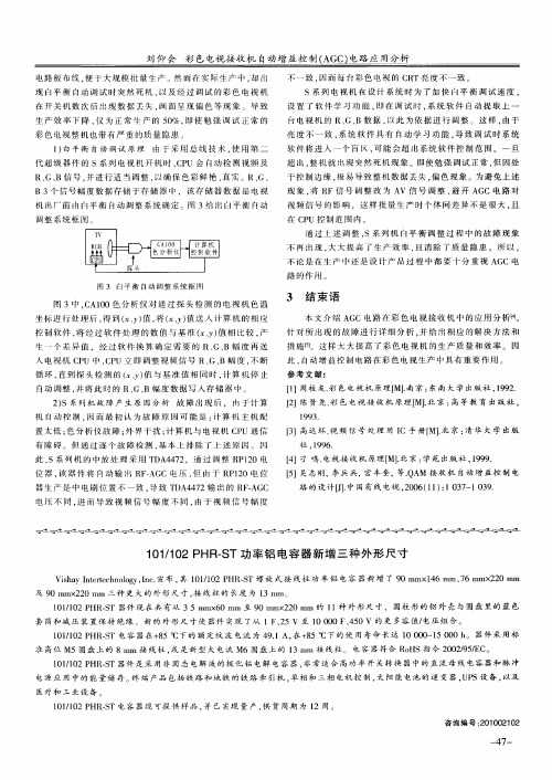
图 3 白平 衡 自动 调 整 系 统 框 图
图 3中 . A1 0色 分 析 仪 对 通 过 探 头 检 测 的 电视 机 色 温 C 0 坐 标 进行 处理 后 , 到 ( y 值 , ( y 值 送 人 计 算 机 的相 应 得 、) 将 、 ) 控 制 软 件 , 经 过 软 件 处 理 的数 值 与基 准 ( Y 值 相 比较 , 将 、 ) 产
调 整 系 统 框 图
通 过上述调整 , S系 列 机 自平 衡 调 整 过 程 中 的 故 障 现 象
不 再 } 现 . 大 提 高 r生 产 效 率 , 消 除 了质 量 隐 患 。所 以 , } _ 大 5 且
不 论 是 在 生 产 巾 还 是 设 计 产 品过 程 中 都 要 十 分 重 视 A C电 G 路 的作 用 。
SMC产品说明书:PPA100 PPA101 PPA102型号的Compact Manometer

Instruction Manual Compact ManometerPPA100 / PPA101 / PPA102The intended use of this product is for pressure measurement.These safety instructions are intended to prevent hazardous situations and/or equipment damage. These instructions indicate the level of potential hazard with the labels of “Caution,” “Warning” or “Danger.”They are all important notes for safety and must be followed in addition to International Standards (ISO/IEC) *1), and other safety regulations. *1)ISO 4414: Pneumatic fluid power - General rules relating to systems. ISO 4413: Hydraulic fluid power - General rules relating to systems.IEC 60204-1: Safety of machinery - Electrical equipment of machines. (Part 1: General requirements)ISO 10218-1: Robots and robotic devices - Safety requirements for industrial robots - Part 1: Robots.• Refer to product catalogue, Operation Manual and Handling Precautions for SMC Products for additional information. • Keep this manual in a safe place for future reference.CautionCaution indicates a hazard with a low level of risk which, if not avoided, could result in minor or moderate injury.WarningWarning indicates a hazard with a medium level of riskwhich, if not avoided, could result in death or serious injury.DangerDanger indicates a hazard with a high level of risk which, ifnot avoided, will result in death or serious injury.Warning• Always ensure compliance with relevant safety laws and standards.• All work must be carried out in a safe manner by a qualified person in compliance with applicable national regulations.• Refer to the operation manual or catalogue on the SMC website (URL: https://) for further Safety Instructions.2 Specifications2.1General specificationsModelPPA100 High pressure PPA101 Vacuum PPA102 Low pressure Rated pressure range-0.1 to 1 MPa -101 to 10 kPa -10 to 100kPaDisplay method 3 digit LCD with backlight Pressure displaydiscrimination1/100Minimum display unit kPa - 1 1 MPa 0.01 - -mmHg- 5 - kgf/cm 20.1 0.01 0.01 inHg - 0.2 -psi 1 0.1 0.1 bar 0.1 0.01 0.01Error displayOver pressure, Memory data error,Change battery signFunctionPeak / bottom display, backlight, Auto powerOFF, Zero clear, Units display switchingWithstand pressure 1.5 MPa 200 kPa 200 kPa Applicable fluid Air, Non-corrosive gases, non-flammable gas Power supply voltage 3 VDC, Type AA dry cell x 2 pcs.Battery life12 months continuous operation(without backlight, at 25°C)Response speed 250 ms Display accuracy ±2% F.S. (at 25°C) Repeatability ±1% F.S. (at 25°C) Temperaturecharacteristics±3% F.S. (0 to 50°C with 25°C standard)Connection port size M5 x 0.8 Operatingtemperature range 0 to 50°C (no condensation)Operating humidityrange35 to 85% RH (no condensation)Enclosure rating IP40 Weight 100 g (Unit: 50 g, Battery: 50 g) *1) Batteries (manganese R6 or alkaline LR6) not included.*2) For the type without the unit switching function are fixed to SI units (kPa or MPa.*3) With regard to the compatibility condition for EMC, the pressure display value variation is ±15% F.S. or less.WarningSpecial products (-X) might have specifications different from those shown in this section. Contact SMC for specific drawings.3 Installation3.1 InstallationWarning• Do not install the product unless the safety instructions have been read and understood.3.2 EnvironmentWarning• Do not use in an environment where corrosive gases, chemicals, salt water or steam are present.• Do not use in an explosive atmosphere.• Do not expose to direct sunlight. Use a suitable protective cover.• Do not install in a location subject to vibration or impact in excess of the product’s specifications.• Do not operate in a location exposed to radiant heat that would result in temperatures in excess of the product’s specifications.3.3 PipingCaution• Before connecting piping be sure to clean up chips, cutting oil, dust etc. • When installing piping or fittings, ensure sealant material does not enter inside the port. When using seal tape, leave 1 thread exposed on the end of the pipe/fitting.• Tighten fittings to the specified tightening torque.3.4 LubricationCaution• SMC products have been lubricated for life at manufacture, and do not require lubrication in service.• If a lubricant is to be used in the system, refer to catalogue for details.4 Settings4.1 Initial SettingPerform initial setting when using for the first time and after changing the batteries, as the unit will display a memory data error.1. Confirmation of displayWhen power is applied, if there is nothing on the display, proceed to step 2.If “Err” Is displayed on the LCD, switch the power OFF and ON again. The display should clear. Proceed to step 2.2. Press and hold the POWER button for 6 seconds or more.The unit will move into the zero-clear mode. When this happens “CAL” will be displayed.3. Release the POWER button.When zero clear is finished, the unit will operate.4.2 Power ONPress the POWER button. The power will turn ON.When pressed and held for 6 seconds or more the unit will move into zero-clear mode.4.3 Power OFFPress and hold the POWER button for 3 seconds or more.The power will turn OFF.The power will also turn OFF If there is no button operation for 5 minutes or more (auto power OFF function).4.4 Units Display Switching1. Press and hold the POWER and LIGHTbuttons for 3 seconds or more.The units on the LCD display will flash.2. Press the LIGHT buttonThe units will change (refer to the units table).3. Press the POWER buttonThe units are set and the units display setting is complete.(For products with units switching function).Units availableHigh pressure (PPA100) Vacuum pressure(PPA101) Low pressure (PPA102) MPa > bar > psi > kgfkPa > bar > psi > inHg > mmHgkPa > bar > psi > kgf4.5 Peak / Bottom displayPress the POWER button. • For Peak displayTo display the maximum pressure value, with “P” displayed on the LCD. The display will change if the pressure exceeds the pressure being held.Press the POWER button. • For Bottom displayTo display the minimum pressure value, with “b” displayed on the LCD. The display will change if the pressure falls below the pressure being held. Press the POWER to complete the setting.Since this function is combined with the power OFF operation, the button should be released when the “P” or “b” is displayed.4.6 Auto Power OFF functionThe power is turned OFF when there has been no button operation for 5 minutes.(To cancel this function refer to the lock mode function below).4.7 Lock mode functionPress and hold the POWER and LIGHT buttons for 6 seconds or more.The lock mode is activated and the auto power OFF function is cancelled.“L” is displayed on the LCD display.When the power is turned OFF the lock mode is released.4.8 Turning ON the BacklightPress the LIGHT button.The display lights up when the button is pressed. In lock mode it lights up when pressed and turns OFF when pressed again.However the maximum lighting time is approximately one minute.4.9 Zero clear functionPress the POWER button for 6 seconds or more.The zero displayed at atmospheric pressure can be automatically adjusted.This means it is possible to eliminate a display discrepancy at atmospheric pressure. 1. Turn the power OFF.2. Release the supply pressure to atmosphere.3. When the POWER button is pressed and held for 6 seconds or more the zero clear function is performed and “CAL” is displayed on the LCD.ORIGINAL INSTRUCTIONSRefer to the operation manual or catalogue on the SMC website (URL: https:// ) for the How to Order information.Refer to the operation manual or catalogue on the SMC website (URL: https:// ) for outline dimensions.7.1 General maintenanceCaution•Not following proper maintenance procedures could cause the productto malfunction and lead to equipment damage.• If handled improperly, compressed air can be dangerous.Maintenance of pneumatic systems should be performed only by qualified personnel.• Before performing maintenance, turn off the power supply and be sure to cut off the supply pressure. Confirm that the air is released to atmosphere.• After installation and maintenance, apply operating pressure and power to the equipment and perform appropriate functional and leakage tests to make sure the equipment is installed correctly.• If any electrical connections are disturbed during maintenance, ensure they are reconnected correctly and safety checks are carried out as required to ensure continued compliance with applicable national regulations.• Do not make any modification to the product.• Do not disassemble the product, unless required by installation or maintenance instructions. 7.2 Span calibrationWarning• Do not touch the span calibration trimmer except when performing a span calibration.1. Perform zero clear at atmospheric pressure.2. Apply the maximum rated pressure and calibrate the span while comparing with a standard pressure gauge.3. If the displayed value of the compact manometer is “0” after returning to atmospheric pressure, then calibration is complete. If the displayed value is not “0” calibrate again by repeating steps 1 and 2.7.3 Replacing the batteriesWhen the battery voltage becomes low the entire LCD display will flash. When the LCD is flashing, replace the batteries. Use 2 x AA dry cell batteries.Caution• To replace the batteries, turn OFF the power and replace them within approximately 30 seconds.• If not completed within 30 seconds “Err” will be displayed. • In that case perform zero clear once again.• In the event that the display runs out of control, remove the batteries for one minute or longer and then perform zero clear again before inserting the batteries and turning ON the power.8.1 Limited warranty and disclaimer/compliance requirements Refer to Handling Precautions for SMC Products.This product shall not be disposed of as municipal waste. Check your local regulations and guidelines to dispose of this product correctly, in order to reduce the impact on human health and the environment.10 ContactsRefer to or www.smc.eu for your local distributor / importer.URL: https:// (Global) https://www.smc.eu (Europe) SMC Corporation, 4-14-1, Sotokanda, Chiyoda-ku, Tokyo 101-0021, Japan Specifications are subject to change without prior notice from the manufacturer. © 2021 SMC Corporation All Rights Reserved. Template DKP50047-F-085M。
Extech温湿仪+红外线温度计型号RH101用户手册说明书
用户手册温湿仪+红外线温度计型号 RH101专利申请中简介感谢您购买Extech 温湿仪和红外线温度计。
该仪表测量相对湿度,气温(通过探针测量)和表面温度(通过红外线功能)。
这款仪表的直观背光式大液晶屏由一级和二级显示器以及很多状态指示灯构成。
红外线功能是激光实现的,方便瞄准目标。
如精心使用,本仪表可稳定地工作多年。
功能量程精确度湿度 10.0到95.0% RH ± 3.5% RH到140o F (-20 到60o C) ± 3.0o F (± 2.0o C) 气温 -4红外线温度-58.0 到-4.0o F (-50.0 到-20.0o C) ± 9o F (± 5o C)-4.0 到199.9o F (-20.0 到93.3o C)± 读数的2% 或 ± 4o F (± 2o C)200 到400o F (93o C 到204o C)读数的3%400 到932o F (204o C 到500o C) ±技术规范显示双液晶屏,背光灯和状态指示灯传感器类型湿度:精确电容传感器温度:电热调节器(探针)和红外线响应时间红外线温度: 0.5秒; 探针温度和相对湿度: 3 分钟精度说明精度是针对下列范围64 到82°F (18 到28°C)规定的采样率每秒采样2.5次红外线发射率0.95 (固定)红外线视野范围D/S = 大约 8:1 (D = 距离, S = 点)激光功率低于1mW红外线光谱响应 6 到14 μm (波长)到122o F (0 到50o C); < 80% RH 非冷凝工作条件 32到140o F (-10 到60o C); <80% RH 非冷凝存储条件 14电源9V 电池,10分钟后自动关机电池工作期限大约24小时(如果背光灯和激光同时使用,那么电池寿命将降低到2到3小时)尺寸/重量 5.9 x 2.8 x 1.4” (150 x 72 x 35mm); 8.3 oz. (235g)安全性∙当打出激光光束时应谨慎行事。
HT101
GMPT Materials Engineering Group
9
Heat Treating 101 & CQI-9
Heat Treating of Metallic Materials/金属材料热处理
Principal of heat treating/热处理基本原理: During heating: Formation of Austenite/加热阶段:奧氏体形成 Austenite will be formed from original microstructure of ferrite and pearlite or tempered martensite. /奧氏体由铁素体, 珠光体或回火马氏体转变而成 During cooling: Decomposition of Austenite: CCT diagram /冷却阶段:奧氏体分解-连续冷却转变曲线
GMPT Materials Engineering Group 6
Crystal Structure of phase/晶体结构 Bcc/体心立方晶体 Bcc/体心立方晶体 Fcc/面心立方晶体 Complex orthorhombic / 斜方晶体 Hexagonal /六边形
bct
bct
Heat Treating 101 & CQI-9
3.
CQI-9 (Heat Treat System Assessment)/热 处理系统评估 • What is CQI-9/CQI-9内容 Why is CQI-9 needed/为什么需要CQI-9 • What are CQI-9 requirements/要求 • What heat treatment processes are covered/所涉及的热处理工艺 • What approach should be used in implementing CQI-9/CQI-9实施方法
曼标表面处理讲解
3 防腐蚀涂层表1中是本标准规定的标准符号,用来定义和规范性能和技术要求,这些处理有些可以用不同的不含六价铬表面防腐涂层方式代替。
这样电镀表面处理与锌基铝盐表面防腐处理(锌鳞片粉在工件表面生成很薄的鳞片状锌铝防护层——译者注)系统可以平行使用。
表2是为允许使用不含六价铬的表面防腐涂层的,有特殊应用特征的应用范围规定的。
4 表面处理的标识- 在技术资料(图纸中): 比如防腐蚀- MAN 183-B1或者MAN 183-PHR- 在标准间的名称中: 比如6角螺栓DIN 931-M10x40-10.9- MAN 183-B1本标准编号按照表1符号–OS颜色,仅对根据6.11表1注脚的解释2要注意第1 和第6节规定。
0) 非高强度结构件,强度FK < 8.8/8 且Rm< 800 N/mm1) 机械连接件,强度FK ≥ 8.8/8 符合VDA 235-104.10。
2/ FK 12.9。
2) 仅适用于强度Rm≥ 1200 N/mm3) 按照表2 和OS表面处理方式,又或者没有润滑。
2/ FK 12.9.有要求。
4) 只对材料强度为Rm≥1200 N/mm5) 只允许B4型表面处理,如果外观设计上有要求用黑色。
6) B2类表面处理= Geomet 500 只在特殊情况下要求使用,如果对摩擦系数需要多次拧紧后仍有要求,比如车轮轮枢螺栓。
最大表面处理的厚度参见6.8节规定。
7) 对于B1, B2, B4类型的表面处理,尤其是内螺纹,较小的螺纹外径和带摩擦损耗部位(比如螺纹受力齿面——译者注)表面处理方法,有必要采用合适的表面处理方法。
8) 锌片处理的连接件与黄铜结构件的的配对由于接触腐蚀的原因不允许使用。
9) 强度等级在12/12.9的连接件不允许采用电镀表面处理。
第 2 页共20 页第 3 页共20 页续表2,第 4 页共20 页第 5 页共20 页5 实施程序由于旧汽车规定方面的有原因许多供应商没有能力提供不含六价铬的表面锌鳞片涂层防腐处理,所以这些供应商要被其他有能力的取代。
菲尼克斯电源说明书
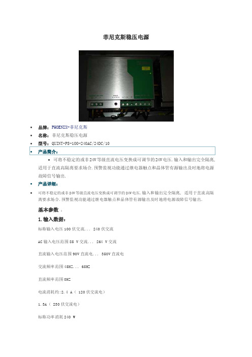
菲尼克斯稳压电源∙品牌:PHOENIX-菲尼克斯∙名称:菲尼克斯稳压电源∙可将不稳定的或非24V等级直流电压变换成可调节的24V电压.输入和输出完全隔离, 适用于直流高隔离要求场合.预警监视功能通过继电器触点和晶体管有源输出及时地将电源故障信号输出.∙产品详细:∙可将不稳定的或非24V等级直流电压变换成可调节的24V电压.输入和输出完全隔离, 适用于直流高隔离要求场合.预警监视功能通过继电器触点和晶体管有源输出及时地将电源故障信号输出.基本参数:1.输入数据:标称输入电压100伏交流... 240伏交流AC输入电压范围85 V交流... 264 V交流直流输入电压范围90V直流电... 350V直流电交流频率范围45HZ... 65HZ直流频率范围0HZ电流消耗约:2.4 A( 120伏交流电)1.3A( 230伏交流电)标称功率消耗240 W瞬间冲击电流“ 15 ”(典型值)电力故障旁路“ 50毫秒”( 120伏交流电)“ 50毫秒”( 230伏交流电)输入保险丝6.3 A备用保险丝推荐10A(16A)2.输出数据:额定输出电压:24伏直流± 1 %设置输出的电压范围:22.5V直流电... 28.5V直流电输出电流:10 A (最多至60 ° C ),15 A(电力升压时)并联:是,当有剩余且增加负载的时候串联:是剩余波值:“ 30 mVPP ”峰值开关电压额定负载:“ 50 mVPP ( 20MHZ)空转最大功耗:4W标称功率损耗最大负荷: 33 W3.普通参数:宽度85mm高度130mm深度130mm重量1.3kg工作电压显示方式:绿屏LED效率:88 %输入/输出绝缘电压值:2kv(常规测试)4kv(模范试验)保护程度:IP20保护等级:1级.用PE连接时平均无故障工作时间:> 500 000 h in acc. wi th IEC 61709 (SN 29500)操作环境温度:-25 ℃ ... 70 ℃(>60 ℃降额值)环境温度(储存/运输):-40 ℃ ... 85 ℃操作环境可允许的最大湿度值:100 %(允许冷凝)组装说明:水平0c m,垂直5c m。
菲尼克斯电气开关电源中文样本
INTERFACE创新电源——系统的可靠保证菲尼克斯电气中国公司地址:南京市江宁开发区菲尼克斯路36号南京江宁236信箱电话:(025)52121888传真:(025)52121555/800 8289722邮编:211100h t t p: //e-mail: phoenix@ CN 11/12 INTERFACE 创新电源TNR 5768710/10.2011-01 Printed In China© PHOENIX CONTACT2011突破性技术——电源解决方案创新促进发展。
菲尼克斯电气的电源产品无疑印证了这一宗旨。
在对理想的电源探索中,我们洞悉市场,与客户密切合作,坚持与执着,不断创造出卓越的新产品技术。
我们的目标是最大程度提高您的设备和系统的可用性。
QUINT电源提供最优产品功能,三个新产品系列在各自领域里树立了新的标杆。
新产品采用ACB技术的冗余模块ACB(自动电流平衡)技术可使您的冗余电源系统的使用寿命翻倍。
该技术确保一定范围内所有的电源平衡输出。
QUINT ORING冗余模块的ACB技术还可检测临界工作状态,并为您提供提前预警。
新产品采用IQ技术的不间断电源具有持续电池监控和智能管理功能的IQ技术可随时为您提供电池的充电状态、剩余工作时间和使用寿命等相关信息。
智能通信功能将预警您危险工况的出现。
这可减少维护工作量,提升系统可用性。
新产品采用SFB技术的DC/DC变换器SFB(选择性触发)技术可在一旦输出回路出现短路时,可靠地切断故障回路。
在短路情况下,将能提供6倍额定输出电流,维持12ms时间。
因此,SFB技术能够可靠地触发标准断路器。
您可快速地进行故障定位,并确保系统的重要设备继续工作。
——采用SFB技术为系统有效性提供最高保证新一代紧凑型QUINT电源,将最大程度地保证系统的有效性。
该电源采用SFB技术(选择性触发技术),能在12ms内输出6倍的额定电流,可靠快速地触发标准断路器脱扣。
MRF101BN和MRF101AN RF 设备数据手册说明书

MRF101BN MRF101ANMRF101AN MRF101BN1RF Power LDMOS TransistorsHigh Ruggedness N--ChannelEnhancement--Mode Lateral MOSFETsThese devices are designed for use in VHF/UHF communications,VHF TV broadcast and aerospaceapplications as well as industrial,scientific and medical applications.The devices are exceptionally rugged and exhibit high performance up to 250MHz.Typical Performance:V DD =50VdcFrequency (MHz)Signal TypeP out (W)G ps (dB)ηD (%)13.56CW 130CW 27.179.627CW 130CW 24.081.540.68(1)CW 120CW 23.881.550CW 115CW 23.079.581.36CW 130CW 23.280.887.5–108CW 110CW 21.377.1136–174(2,3)CW104CW 21.276.5230(4)Pulse(100μsec,20%Duty Cycle)115Peak21.176.7Load Mismatch/RuggednessFrequency (MHz)Signal TypeVSWR P in (W)Test Voltage Result 40.68CW>65:1at all Phase Angles 0.64Peak (3dB Overdrive)50No Device Degradation 230Pulse(100μsec,20%Duty Cycle)>65:1at all Phase Angles1.8Peak (3dB Overdrive)50No Device Degradation1.Measured in 40.68MHz reference circuit (page 5).2.Measured in 136–174MHz VHF broadband reference circuit (page3.The values shown are the center band performance numbers across the indicated frequency range.4.Measured in 230MHz fixture (page 13).Features ∙Mirror pinout versions (A and B)to simplify use in a push--pull,two--up configuration∙Characterized from 30to 50V ∙Suitable for linear application∙Integrated ESD protection with greater negative gate--source voltage range for improved Class C operation∙Included in NXP product longevity program with assured supply for a minimum of 15years after launchTypical Applications∙Industrial,scientific,medical (ISM)–Laser generation –Plasma etching –Particle accelerators–MRI and other medical applications–Industrial heating,welding and drying systems∙Radio and VHF TV broadcast ∙HF and VHF communications ∙Switch mode power supplies Document Number:MRF101ANRev.0,11/2018Technical Data1.8–250MHz,100W CW,50VWIDEBANDRF POWER LDMOS TRANSISTORSMRF101AN MRF101BNTO--220--3LMRF101BNTO--220--3LMRF101ANGSDDS GNote:Exposed backside of the packageand tab also serves as a source terminal for the transistor.BacksideSS2RF Device Data NXP SemiconductorsMRF101AN MRF101BN Table 1.Maximum RatingsRatingSymbol Value Unit Drain--Source Voltage V DSS –0.5,+133Vdc Gate--Source Voltage V GS –6.0,+10Vdc Operating VoltageV DD 50Vdc Storage Temperature Range T stg –65to +150︒C Case Operating Temperature Range T C –40to +150︒C Operating Junction Temperature Range (1,2)T J –40to +175︒C Total Device Dissipation @T C =25︒C Derate above 25︒CP D1820.91W W/︒CTable 2.Thermal CharacteristicsCharacteristicSymbol Value (2,3)Unit Thermal Resistance,Junction to CaseCW:Case Temperature 77︒C,150W CW,50Vdc,I DQ =100mA,40.68MHz R θJC 1.1︒C/W Thermal Impedance,Junction to CasePulse:Case Temperature 73︒C,113W Peak,100μsec Pulse Width,20%Duty Cycle,50Vdc,I DQ =100mA,230MHzZ θJC0.37︒C/WTable 3.ESD Protection CharacteristicsTest MethodologyClass Human Body Model (per JS--001--2017)1B,passes 1000V Charge Device Model (per JS--002--2014)C3,passes 1200VTable 4.Electrical Characteristics (T A =25︒C unless otherwise noted)CharacteristicSymbolMinTypMaxUnitOff CharacteristicsGate--Source Leakage Current (V GS =5Vdc,V DS =0Vdc)I GSS ——1μAdc Drain--Source Breakdown Voltage (V GS =0Vdc,I D =50mAdc)V (BR)DSS 133——Vdc Zero Gate Voltage Drain Leakage Current (V DS =100Vdc,V GS =0Vdc)I DSS——10μAdcOn CharacteristicsGate Threshold Voltage(V DS =10Vdc,I D =290μAdc)V GS(th) 1.7 2.2 2.7Vdc Gate Quiescent Voltage(V DS =50Vdc,I D =100mAdc)V GS(Q)— 2.5—Vdc Drain--Source On--Voltage (V GS =10Vdc,I D =1Adc)V DS(on)—0.45—Vdc Forward Transconductance (V DS =10Vdc,I D =8.8Adc)g fs—7.1—S1.Continuous use at maximum temperature will affect MTTF.2.MTTF calculator available at /RF/calculators .3.Refer to AN1955,Thermal Measurement Methodology of RF Power Amplifiers.Go to /RF and search for AN1955.(continued)MRF101AN MRF101BN3RF Device DataNXP SemiconductorsTable 4.Electrical Characteristics (T A =25︒C unless otherwise noted)(continued)CharacteristicSymbolMinTypMaxUnitDynamic CharacteristicsReverse Transfer Capacitance(V DS =50Vdc ±30mV(rms)ac @1MHz,V GS =0Vdc)C rss —0.96—pF Output Capacitance(V DS =50Vdc ±30mV(rms)ac @1MHz,V GS =0Vdc)C oss —43.4—pF Input Capacitance(V DS =50Vdc,V GS =0Vdc ±30mV(rms)ac @1MHz)C iss—149—pFTypical Performance —230MHz (In NXP 230MHz Fixture,50ohm system)V DD =50Vdc,I DQ =100mA,P in =0.9W,f =230MHz,100μsec Pulse Width,20%Duty Cycle Common--Source Amplifier Output Power P out —115—W Power Gain G ps —21.1—dB Drain EfficiencyηD—76.7—%Table 5.Load Mismatch/Ruggedness (In NXP 230MHz Fixture,50ohm system)I DQ =100mAFrequency (MHz)Signal TypeVSWR P in (W)Test Voltage,V DDResult230Pulse(100μsec,20%Duty Cycle)>65:1at all Phase Angles1.8Peak (3dB Overdrive)50No Device DegradationTable 6.Ordering InformationDeviceShipping InformationPackageMRF101AN MPQ =250devices (50devices per tube,5tubes per box)TO--220--3L (Pin 1:Gate,Pin 2:Source,Pin 3:Drain)MRF101BNTO--220--3L (Pin 1:Drain,Pin 2:Source,Pin 3:Gate)4RF Device Data NXP SemiconductorsMRF101AN MRF101BNTYPICAL CHARACTERISTICS1100V DS,DRAIN--SOURCE VOLTAGE(VOLTS)Figure1.Capacitance versus Drain--Source Voltage C,CAPACITANCE(pF)1010000.1MRF101AN MRF101BN5RF Device DataNXP Semiconductors40.68MHz COMPACT REFERENCE CIRCUIT (MRF101AN)—0.7"⨯2.0"(1.8cm ⨯5.0cm)Table 7.40.68MHz Performance (In NXP Reference Circuit,50ohm system)V DD =50Vdc,I DQ =100mA,P in =0.50W,CWFrequency (MHz)P out (W)G ps (dB)ηD (%)40.6812023.881.56RF Device Data NXP SemiconductorsMRF101AN MRF101BN 40.68MHz COMPACT REFERENCE CIRCUIT (MRF101AN)—0.7"⨯2.0"(1.8cm ⨯5.0cm)Figure 2.MRF101AN Compact Reference Circuit Component Layout and Assembly Example —40.68MHzFigure 3.MRF101AN Compact Reference CircuitBoardaaa--032274Table 8.MRF101AN Compact Reference Circuit Component Designations and Values —40.68MHzPartDescriptionPart NumberManufacturer B1Short RF Bead 2743019447Fair-Rite C1,C582pF Chip Capacitor GQM2195C2E820GB12D Murata C2,C4200pF Chip Capacitor GQM2195C2A201GB12D Murata C333pF Chip Capacitor GQM2195C2E330GB12D Murata C6,C7,C8,C9,C101000pF Chip Capacitor GRM2165C2A102JA01D Murata C111μF Chip Capacitor GJ821BR71H105KA12L Murata C12,C1310nF Chip Capacitor GRM21BR72A103KA01B Murata C141μF Chip Capacitor C3216X7R2A105K160AA TDK L1150nH Chip Inductor 0805WL151JT ATC L217.5nH,4Turn Inductor GA3095-ACL Coilcraft L3160nH Square Air Core Inductor 2222SQ-161JEC Coilcraft L4110nH Square Air Core Inductor 2222SQ-111JEB Coilcraft Q1RF Power LDMOS Transistor MRF101ANNXP R175Ω,1/4W Chip Resistor SG73P2ATTD75R0F KOA Speer PCBFR40.09",εr =4.8,2oz.CopperD113958MTLMRF101AN MRF101BN7RF Device DataNXP SemiconductorsTYPICAL CHARACTERISTICS —40.68MHz COMPACT REFERENCE CIRCUIT (MRF101AN)V GS ,GATE--SOURCE VOLTAGE (VOLTS)8060P o u t ,O U T P U T P O W E R (W A T T S )40 3.52.51.51100120014020Figure 4.CW Output Power versus Gate--SourceVoltage at a Constant Input PowerP in ,INPUT POWER (WATTS)8060P o u t ,O U T P U T P O W E R (W A T T S )40010012001402040.68101121f (MHz)P1dB (W)P3dB (W)Figure 5.CW Output Power versus Input PowerP out ,OUTPUT POWER (WATTS)Figure 6.Power Gain and Drain Efficiencyversus CW Output PowerG p s ,P O W E R G A I N (d B )ηD ,D R A I N E F F I C I E N C Y (%)25242802090705030302223262729806040201004060801001201400.5230.10.20.30.40.50.60.721201008RF Device Data NXP SemiconductorsMRF101AN MRF101BN40.68MHz COMPACT REFERENCE CIRCUIT(MRF101AN)fMHzZ sourceΩZ loadΩ40.6824.0+j12.614.2–j2.5Z source=Testcircuit impedance as measured fromgate to ground.Z load=Test circuit impedance as measuredfromdrain toground.Figure7.Series Equivalent Source and Load Impedance—40.68MHzZ source Z load50Ω50ΩMRF101AN MRF101BN9RF Device DataNXP Semiconductors136–174MHz COMPACT VHF BROADBAND REFERENCE CIRCUIT (MRF101AN)—0.7"⨯2.0"(1.8cm ⨯5.0cm)Table 9.136–174MHz VHF Broadband Performance (In NXP Reference Circuit,50ohm system)V DD =50Vdc,I DQ =100mA,P in =0.79W,CWFrequency (MHz)P out (W)G ps (dB)ηD (%)13511721.780.015510421.276.517510721.375.4136–174MHz COMPACT VHF BROADBAND REFERENCE CIRCUIT(MRF101AN)—0.7"⨯2.0"(1.8cm⨯5.0cm)Figure8.MRF101AN Compact Reference Circuit Component Layout and Assembly Example—136–174MHzFigure9.MRF101AN Compact Reference Circuit BoardTable10.MRF101AN Compact VHF Broadband Reference Circuit Component Designations and Values—136–174MHz Part Description Part Number ManufacturerB1Short RF Bead2743019447Fair-RiteC139pF Chip Capacitor GQM2195C2E390GB12D MurataC2,C5,C6,C7,C8,C12510pF Chip Capacitor GRM2165C2A511JA01D MurataC368pF Chip Capacitor GQM2195C2E680GB12D MurataC427pF Chip Capacitor GQM2195C2E270GB12D MurataC910pF Chip Capacitor GQM2195C2E100FB12D MurataC111μF Chip Capacitor GJ821BR71H105KA12L MurataC1310nF Chip Capacitor GRM21BR72A103KA01B MurataC141μF Chip Capacitor C3216X7R2A105K160AA TDKL122nH Chip Inductor0805WL220JT ATCL212nH Chip Inductor0805WL120JT ATCL3,L4,L668nH Air Core Inductor1812SMS-68NJLC CoilcraftL512nH,3Turn Inductor GA3094-ALC CoilcraftQ1RF Power LDMOS Transistor MRF101AN NXPR175Ω,1/4W Chip Resistor SG73P2ATTD75R0F KOA SpeerPCB FR40.09",εr=4.8,2oz.Copper D113958MTLTYPICAL CHARACTERISTICS —136–174MHzCOMPACT VHF BROADBAND REFERENCE CIRCUIT (MRF101AN)20150f,FREQUENCY (MHz)26259085807565130120ηD ,D R A I N E F F I C I E N C Y (%)G p s ,P O W E R G A I N (d B )242322211715516016517070110P o u t ,O U T P U T P O W E R (W A T T S )14514017513519100180P in,INPUT POWER (WATTS)0P o u t ,O U T P U T P O W E R (W A T T S )806040200.40.61201000.20.8140 1.027202422807570G p s ,P O W E R G A I N (d B )20406026858025232110012014065605550ηD ,D R A I N E F F I C I E N C Y (%)Figure 10.Power Gain,Drain Efficiency and CW Output Power versus Frequency at a Constant Input PowerFigure 11.CW Output Power versus Input Power and FrequencyP out ,OUTPUT POWER (WATTS)Figure 12.Power Gain and Drain Efficiency versusCW Output Power and Frequency191817454035136–174MHz COMPACT VHF BROADBAND REFERENCE CIRCUIT(MRF101AN)f MHz Z sourceΩZ loadΩ135 6.8+j10.29.5+j5.2145 6.2+j10.29.9+j5.9155 5.3+j10.810.2+j6.2165 4.4+j11.910.0+j5.9175 3.9+j13.48.8+j5.0Z source=Test circuit impedance as measured fromgate to ground.Z load=Test circuit impedance as measured fromdrain to ground.Figure13.Series Equivalent Source and Load Impedance—136–174MHzZ source Z load50Ω50Ω230MHz FIXTURE(MRF101AN)—4.0"⨯5.0"(10.2cm⨯12.7cm)aaa--031939Figure14.MRF101AN Fixture Component Layout—230MHzTable11.MRF101AN Fixture Component Designations and Values—230MHzPart Description Part Number Manufacturer B1Long Ferrite Bead2743021447Fair-RiteC1,C2,C1018pF Chip Capacitor ATC100B180JT500XT ATCC343pF Chip Capacitor ATC100B430JT500XT ATCC4,C131000pF Chip Capacitor ATC800B102JT50XT ATCC50.1μF Chip Capacitor GRM319R72A104KA01D MurataC610nF Chip Capacitor C1210C103J5GACTU KemetC7 2.2μF Chip Capacitor C3225X7R1H225K TDKC847μF,16V Tantalum Capacitor T491D476K016AT KemetC951pF Chip Capacitor ATC100B510JT500XT ATCC1116pF Chip Capacitor ATC100B160JT500XT ATCC12470pF Chip Capacitor ATC800B471JW50XT ATCC140.1μF Chip Capacitor C1812104K1RACTU KemetC15 2.2μF Chip Capacitor C3225X7R2A225K TDKC16 2.2μF Chip Capacitor HMK432B7225KM-T Taiyo YudenC17220μF,100V Electrolytic Capacitor MCGPR100V227M16X26MulticompL139nH Chip Inductor1812SMS-39NJLC CoilcraftL246nH Chip Inductor1010VS-46NME CoilcraftL317.5nH,4Turn Inductor GA3095-ALC CoilcraftR1470Ω,1/4W Chip Resistor CRCW1206470RFKEA VishayPCB Rogers AD255C,0.030",εr=2.55,2oz.Copper D113651MTLTYPICAL CHARACTERISTICS —230MHz FIXTURE,T C =25_C (MRF101AN)0V GS ,GATE--SOURCE VOLTAGE (VOLTS)Figure 15.Output Power versus Gate--SourceVoltage at a Constant Input PowerP o u t ,O U T P U T P O W E R (W A T T S )P E A K755025 1.52 2.531251000.51P in ,INPUT POWER (dBm)PEAK 514943P o u t ,O U T P U T P O W E R (d B m )P E A K4733302127245318230110128f (MHz)P1dB (W)P3dB (W)Figure 16.Output Power versus Input PowerP out ,OUTPUT POWER(WATTS)PEAKFigure 17.Power Gain and Drain Efficiency versus Output Power and Quiescent CurrentG p s ,P O W E R G A I N (d B )ηD ,D R A I N E F F I C I E N C Y (%)3300806040203301080706050403020P out ,OUTPUT POWER (WATTS)PEAKFigure 18.Power Gain and Drain Efficiencyversus Output PowerG p s ,P O W E R G A I N (d B )ηD ,D R A I N E F F I C I E N C Y (%)0P out ,OUTPUT POWER (WATTS)PEAKFigure 19.Power Gain versus Output Powerand Drain--Source Voltage20G p s ,P O W E R G A I N (d B )16145075100182522150451001251503003002441393715230MHz FIXTURE (MRF101AN)f MHz Z sourceΩZ load Ω2302.1+j5.95.5+j3.2Z source =Test circuitimpedance as measured fromgate to ground.Z load=Test circuit impedance asmeasured from drain toground.Figure 20.Series Equivalent Source and Load Impedance —230MHzZ source Z load50Ω50ΩPACKAGE DIMENSIONSPRODUCT DOCUMENTATION,SOFTWARE AND TOOLS Refer to the following resources to aid your design process.Application Notes∙AN1955:Thermal Measurement Methodology of RF Power AmplifiersEngineering Bulletins∙EB212:Using Data Sheet Impedances for RF LDMOS DevicesSoftware∙Electromigration MTTF Calculator∙RF High Power Model∙.s2p FileDevelopment Tools∙Printed Circuit BoardsTo Download Resources Specific to a Given Part Number:1.Go to /RF2.Search by part number3.Click part number link4.Choose the desired resource from the drop down menuREVISION HISTORYThe following table summarizes revisions to this document.Revision Date Description 0Nov.2018∙Initial release of data sheetRF Device DataNXP Semiconductors How to Reach Us:Home Page: Web Support:/support Information in this document is provided solely to enable system and software implementers to use NXP products.There are no express or implied copyright licenses granted hereunder to design or fabricate any integrated circuits based on the information in this document.NXP reserves the right to make changes without further notice to any products herein.NXP makes no warranty,representation,or guarantee regarding the suitability of its products for any particular purpose,nor does NXP assume any liability arising out of the application or use of any product or circuit,and specifically disclaims any and all liability,including without limitation consequential or incidental damages.“Typical”parameters that may be provided in NXP data sheets and/or specifications can and do vary in different applications,and actual performance may vary over time.All operating parameters,including “typicals,”must be validated for each customer application by customer’s technical experts.NXP does not convey any license under its patent rights nor the rights of others.NXP sells products pursuant to standard terms and conditions of sale,which can be found at the following address:/SalesTermsandConditions .NXP and the NXP logo are trademarks of NXP B.V.All other product or service names are the property of their respective owners.E 2018NXP B.V.MRF101BN MRF101AN。
卡梅伦液压数据手册(第 20 版)说明书
iv
⌂
CONTENTS OF SECTION 1
☰ Hydraulics
⌂ Cameron Hydraulic Data ☰
Introduction. . . . . . . . . . . . . ................................................................ 1-3 Liquids. . . . . . . . . . . . . . . . . . . ...................................... .......................... 1-3
4
Viscosity etc.
Steam data....................................................................................................................................................................................... 6
1 Liquid Flow.............................................................................. 1-4
Viscosity. . . . . . . . . . . . . . . . . ...................................... .......................... 1-5 Pumping. . . . . . . . . . . . . . . . . ...................................... .......................... 1-6 Volume-System Head Calculations-Suction Head. ........................... 1-6, 1-7 Suction Lift-Total Discharge Head-Velocity Head............................. 1-7, 1-8 Total Sys. Head-Pump Head-Pressure-Spec. Gravity. ...................... 1-9, 1-10 Net Positive Suction Head. .......................................................... 1-11 NPSH-Suction Head-Life; Examples:....................... ............... 1-11 to 1-16 NPSH-Hydrocarbon Corrections.................................................... 1-16 NPSH-Reciprocating Pumps. ....................................................... 1-17 Acceleration Head-Reciprocating Pumps. ........................................ 1-18 Entrance Losses-Specific Speed. .................................................. 1-19 Specific Speed-Impeller. .................................... ........................ 1-19 Specific Speed-Suction...................................... ................. 1-20, 1-21 Submergence.. . . . . . . . . ....................................... ................. 1-21, 1-22 Intake Design-Vertical Wet Pit Pumps....................................... 1-22, 1-27 Work Performed in Pumping. ............................... ........................ 1-27 Temperature Rise. . . . . . . ...................................... ........................ 1-28 Characteristic Curves. . ...................................... ........................ 1-29 Affinity Laws-Stepping Curves. ..................................................... 1-30 System Curves.. . . . . . . . ....................................... ........................ 1-31 Parallel and Series Operation. .............................. ................. 1-32, 1-33 Water Hammer. . . . . . . . . . ...................................... ........................ 1-34 Reciprocating Pumps-Performance. ............................................... 1-35 Recip. Pumps-Pulsation Analysis & System Piping...................... 1-36 to 1-45 Pump Drivers-Speed Torque Curves. ....................................... 1-45, 1-46 Engine Drivers-Impeller Profiles. ................................................... 1-47 Hydraulic Institute Charts.................................... ............... 1-48 to 1-52 Bibliography.. . . . . . . . . . . . ...................................... ........................ 1-53
TSG101
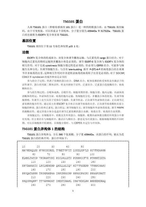
TSG101蛋白人源TSG101蛋白(肿瘤易感基因101蛋白)是一种四跨膜蛋白质,由TSG101基因编码,由于可变剪接,可以形成2个异构体,分子量分别为43944Da和31732Da。
TSG101蛋白质也被称为ESCRT-I复合体亚基TSG101。
基因位置TSG101基因位于第11号染色体短臂p15. 1处。
功能ESCRT-I复合体的组成部分,该复合体调节囊泡运输。
与泛素化的cargo蛋白结合,对于细胞内泛素化的物质运输到多囊泡小体是必须的,调节ESCRT-0复合体与ESCRT-I复合体的相互作用,对于完成cytokinesis细胞分裂过程是必须的,但必须与CEP55结合。
可能参与细胞生长和分化,负调节细胞生长。
与含有late-budding 基序P-[ST]-A-P的病毒蛋白结合来调节许多病毒的出芽,这种相互作用对许多逆转录病毒的病毒粒子出芽是必须的,对于SDCBP, CD63和syndecan的胞外释放是必须的参与的分子过程:钙离子依赖的蛋白结合,DNA结合,配体依赖的核受体转录共激活子的活性调节,蛋白质同源二聚体活性,转录共抑制子活性,泛素结合,泛素蛋白连接酶结合,病毒颗粒结合。
参与的生物过程:自噬体成熟,自噬作用,细胞周期停滞,细胞分裂,胞内运输,内涵体到溶酶体的转运,外泌体的分泌,病毒的胞内运输,角细胞的分化,多囊泡小体的组装,负调节细胞增殖,负调节上皮生长因子受体信号通路,负调节转录,正向调节外泌体的分泌,正向调节泛素依赖的胞吞作用,通过宿主的ESCRT复合体正向调节病毒的出芽,正向调节病毒颗粒从宿主细胞的释放,蛋白的单泛素化,蛋白转运,调节细胞生长,调节细胞外外泌体的组装,调节MAPK 的激酶活性,通过多泡小体分选途径调节泛素依赖的蛋白水解,病毒出芽,病毒的生命周期。
亚细胞定位:在细胞质中,质膜及其外周蛋白,细胞核,晚期内涵体膜及膜的外周蛋白中都有发现,但主要存在与细胞质中,激活后与膜结合,静息是为可溶蛋白,根据细胞周期的不同时期,可以在细胞核中检测到。
ASHCROFT

OPERATIONThe ASHCROFT ®pressure control is a precision device which features a snap action switch.Fixed deadband is available with single or dual SPDT independently adjustable switches with various electrical ratings.Adjustable deadband is available with SPDT switch with various electrical ratings.Several wettedmaterial constructions for compatibility with pressure media may be obtained.Series LP-S switches have a fixed deadband which will be within the limits noted on the nameplate.Series LP-D switches may be set to operate simultaneously or up to 85 percent of the range apart.The deadband of each switch will be within the limits noted on the nameplate.Series LP-A switches may be set to operate with any deadband within the limits shown on the nameplate.MOUNTINGThe “L ”Series ASHCROFT snap action pressure switch has a NEMA-4 enclosure which is an epoxy coated aluminum casting.T wo holes in the integral bracket are used to surface mount the control.Location of these holes is shown on the general dimension drawings.An optional pipe mounting bracket is also available.Mount on a vibration free surface or pipe in any orien-tation.When tightening control to pressure line, always use the wrench flats or hex on the pressure connection.NEVER TIGHTEN BY TWISTING THE CASE.CONDUIT CONNECTIONSOne 3⁄4NPT hole fitted with a shipping plug, and two additional knock outs are provided.The knockouts may be removed by placing a screwdriver in the slot and rapping sharply with a hammer It is recommended that T eflon tape or other sealant be used on conduit bushings or plug threads to ensure integrity of the enclosure.ELECTRICAL CONNECTIONRemove cover, held in place by two screws.On all units except one with terminal blocks – wire directly to the switch according to circuit requirements.Units with terminal blocks – wire directly to terminal blocks as required.T erminals are marked common (C), normally open (NO) and normally closed (NC).4.126.091/2NPT MALE &1/4NPT FEMALE8psi Rangesin.H 2O RangesLEFT SWITCH RIGHT SWITCH TERMINAL BLOCKSERVICE LEADS TO THESE TERMINALSSTANDARD RANGES15, 30, 60, 100, 200, 400, 600 psi *1000, 2000, 3000 psi 30˝Hg vac.-0 psiSTANDARD RANGES 30, 60, 100, 150 in.H 2O 15 in.H 2O-15 in.H 2O2.7 lbs.3.4 lbs.SETPOINT ADJUSTMENTSSetpoints are changed by means of the setpoint adjusters The LP-S single switch has one adjuster and the LP-A adjustable deadband and LP-D dual switch each have two adjusters.On switches with two adjusters, the one on the left is referred to as “A”and the right one is referred to as “B”;see illustration.Setpoints can be adjusted from 15 to 100 percent of full range on increasing pressure.SERIES LP-S SINGLE SWITCHRemove cover.For setpoint adjustment on either increasing or decreasing pressure to within ±1% of nominal range, mount the switch on a calibration stand and use a suitable reference such as an ASHCROFT ®Duragauge or test gauge.Monitor switch with a light or meter.Pressurize the system to the required set-point pressure.If setpoint is on increasing pressure, turn adjuster so that switch operates (if common – normally closed circuit is being monitored light goes off).If setpoint is on decreasing pressure, turn adjuster so that switch resets (if common – normally closed circuit is being monitored light comes on).When the setpoint has been achieved, raise and lower the pressure to ensure that the setpoint is correct.The deadband (difference between the operate and resetpressures) may be verified at this time to be between the values noted on the nameplate label.SERIES LP-D DUAL SWITCHRemove cover.For setpoint adjustment on either increasing or decreasing pressure to within ±1% of nominal range, mount the switch on a calibration stand and use a suitable reference such as an ASHCROFT ®Duragauge or test gauge.Monitor switch with a light or meter.Pressurize the system to the required higher setpoint pressure and turn adjuster “B”until the switch operates or resets as required.See discussion of increasing or decreasing pressure setpoints and deadband verification under Series LP-S Single Switch.When the setpoint has been achieved, raise and lower the pressure to ensure that the setpoint is correct.Then reduce system pressure to the required lower setpoint pressure and turn adjuster “A”until the switch operates or resets as required.Verify this setpoint by raising and lowering pressure.Now increase system pressure to higher setpoint and make final adjustment on “B.”AB02040600204060SERIES LP-A ADJUSTABLE DEADBAND SWITCHRemove cover.Adjuster “B”controls the operating point of the switch on increasing pressure.Adjuster “A”controls the re-setpoint of the switch on decreasing pressure.For accurate setpoint adjustment, mount the switch on a calibration stand and use a suitable reference such as an ASHCROFT ®Duragauge or test gauge.Monitor switch with a light or meter.Pressurize the system to the required setpoint pressure.T urn adjuster “B”until switch operates.Then lower pressure to the re-setpoint, turn adjuster “A”until the switch resets.Now increase pressure to the operating point and make final adjustment on “B”.Raise and lower pressure to ensure that the setpoint and re-setpoint are correct.SOME PRECAUTIONS TO OBSERVEDo not loosen the screws holding the precision switch element(s)or mounting bracket in place.Nameplate PROOF pressure should not be exceeded.Inter-mittent operation up to proof pressure is permissible, however,some change of setpoint may be noted.Operation and correct setpoint actuation should be routinely tested.Note –Since vacuum models are already above setpoint atatmosphere, the Normally Open (NO) circuit will be closed as received.。
HD 101 保火漏Model A(铑铁)保火漏保护有限公司技术数据说明书
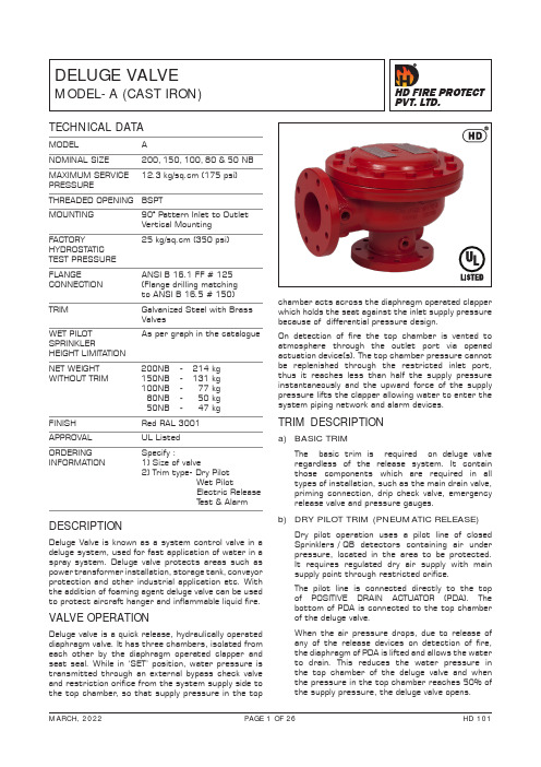
DELUGE VALVE MODEL- A (CAST IRON)TECHNICAL DATAMODEL ANOMINAL SIZE 200, 150, 100, 80 & 50 NB MAXIMUM SERVICE 12.3 kg/sq.cm (175 psi)PRESSURE THREADED OPENING BSPTMOUNTING 90° Pattern Inlet to OutletVertical MountingFACTORY25 kg/sq.cm (350 psi) HYDROSTATIC TEST PRESSUREFLANGEANSI B 16.1 FF # 125 CONNECTION (Flange drilling matchingto ANSI B 16.5 # 150)TRIM Galvanized Steel with Brass Valves WET PILOT As per graph in the catalogue SPRINKLERHEIGHT LIMITATION NET WEIGHT 200NB - 214 kg WITHOUT TRIM 150NB - 131 kg 100NB - 77 kg 80NB - 50 kg 50NB - 47 kg FINISH Red RAL 3001APPROVAL UL ListedORDERING Specify : INFORMATION 1) Size of valve2) Trim type- Dry Pilot Wet Pilot Electric ReleaseT est & AlarmDESCRIPTIONDeluge Valve is known as a system control valve in a deluge system, used for fast application of water in a spray system. Deluge valve protects areas such as power transformer installation, storage tank, conveyor protection and other industrial application etc. With the addition of foaming agent deluge valve can be used to protect aircraft hanger and inflammable liquid fire.VALVE OPERATIONDeluge valve is a quick release, hydraulically operated diaphragm valve. It has three chambers, isolated from each other by the diaphragm operated clapper and seat seal. While in ‘SET’ position, water pressure is transmitted through an external bypass check valve and restriction orifice from the system supply side to the top chamber , so that supply pressure in the topchamber acts across the diaphragm operated clapperwhich holds the seat against the inlet supply pressure because of differential pressure design.On detection of fire the top chamber is vented to atmosphere through the outlet port via opened actuation device(s). The top chamber pressure cannot be replenished through the restricted inlet port, thus it reaches less than half the supply pressure instantaneously and the upward force of the supply pressure lifts the clapper allowing water to enter the system piping network and alarm devices.TRIM DESCRIPTIONa) BASIC TRIMThe basic trim is required on deluge valve regardless of the release system. It contain those components which are required in all types of installation, such as the main drain valve, priming connection, drip check valve, emergencyrelease valve and pressure gauges.b) DRY PILOT TRIM (PNEUMATIC RELEASE)Dry pilot operation uses a pilot line of closed Sprinklers / QB detectors containing air under pressure, located in the area to be protected. It requires regulated dry air supply with main supply point through restricted orifice.The pilot line is connected directly to the top of POSITIVE DRAIN ACTUATOR (PDA). The bottom of PDA is connected to the top chamber of the deluge valve.When the air pressure drops, due to release of any of the release devices on detection of fire, the diaphragm of PDA is lifted and allows the water to drain. This reduces the water pressure in the top chamber of the deluge valve and when the pressure in the top chamber reaches 50% ofthe supply pressure, the deluge valve opens.The direct drain of PDA start when the top chamber pressure of deluge valve reaches approximately 0.7 kg/sq.cm. This positive drain will not permit the deluge valve to close unless the PDA is set manually. The recommended air supply pressureis as per TABLE-1.c) WET PILOT TRIM (HYDRAULIC RELEASE)Wet pilot operation uses a pilot line of closed sprinklers containing pressurised water , supplied through the upstream side of the deluge valve, through a restricted orifice. All the release lines are connected to a common release line. Due to release of any one of the releasing devices, the water pressure in the top chamber of the deluge valve reaches 50% of the supply pressure, thedeluge valve opens.CAUTIONWhile using a deluge valve in the wet pilot system the height and the length of the wet pilot detection line is to be limited as given in the wet pilot sprinkler height limitation graph.d) ELECTRIC RELEASE TRIMT o actuate a deluge valve electrically, a solenoid valve is provided to drain the water from the top chamber of the deluge valve. A pressure switch is provided to activate an electric alarm, to shut down the desired equipment or to give “Tripped” indication to the panel.In addition to this two nos of pressure switchs can be used to monitor “Low air pressure” and“Fire condition” when used in dry pilot air line.e) TEST AND ALARM TRIM WITH SPRINKLER ALARMThis trim is supplied with the sprinkler alarm bell, which bells on actuation of the deluge valve. A test valve is provided to test the normaloperation of the sprinkler alarm bell.Note: Trim without Test and Alarm trim, without Drain & drip valve can be supplied for which please contact marketing.RESETTING PROCEDURE(i) Close the upstream side stop valve provide below the deluge valve.(ii) Open both the drain valves and close them when the flow of water has ceased.(iii) Inspect and release if required, or close the section of the detection system subjected to “Fire condition”.(iv) In case of dry pilot detection system, openthe air supply valve to build-up air pressure as shown in TABLE-1. Open the priming valve fully and press hold the knob of PDA till the water pressure gauge indicate full service line pressure, then release the PDA knob. Open theu pstream side of the stop valve provided belowt he deluge valve. No water should flow into thes ystem, this can be checked by depressing thed rip check valve knob.CAUTIONa. Do not close the priming valve, down stream and upstream stop valves, while the system is in service.b. The releasing device must be maintained in the open position, when actuated, to prevent the deluge valve from closure.c. While using a Deluge valve in the wet pilot system the height and the length of the wet pilot detection line is to be limited as shownin the wet pilot sprinkler limitation graph.d. Do not connect the Sprinkler Alarm outlet drain- line to close a common drain as it may create back pressure and Sprinkler Alarm may not fuction.e. Deluge valve must have support to absorb sudden opening or closing vibration shock to the piping.f. The responsibility of maintenance of the protection system and devices in proper operating condition lies with the owner of the system.g. Deluge Valve & its trim shall be maintained at a minimum temperature of 4ºC, Heat tracing is not permitted.h. Deluge Valve must be used in pressurised system.SYSTEM TESTING PROCEDURE(i) Keep the upstream side of the stop valve partially open. Open the upstream side of the drain valve, to maintain a minimum pressure of 3 Kg./sq. cm on the upstream side of the deluge valve. T o avoid water damage close the system side stop valve. This valve is to be kept in openposition after the testing is completed.(ii) Open the system side drain valve of the deluge valve.(iii) Let any of the release devices to trip. This will result in a sudden drop of water pressure in the deluge valve top chamber resulting the deluge valve to open. The water flowing through the down stream side drain valve confirms that the deluge valve has actuated, immediately closethe upstream side stop valve .(iv) Once testing is over reset the valve as per procedure given under heading “RESETTING PROCEDURE FOR THE DELUGE VAL VE”.INSPECTION AND MAINTENANCEAll the newly installed system piping network mustbe flushed properly before placing the deluge valve in service. A qualified and trained person must commission the system. After few initial successful tests an authorised person must be trained to perform inspection and testing of the system. It is recommended to have regular inspection and test run the system as per NFPA guidelines or in accordance with the guideline laid down by the organisation having (i) WARNINGInspection and testing is to be carried out only by authorised and trained personnel. DO NOT TURN OFF the water supply or close any valve to make repair(s) or test the valve, without placing a roving fire patrol in the area protected by the system. Also inform the local security personnel and central alarm station, so that a false alarm is not signalled. It is recommended to carry out physical inspection of the system at least twice in a week.The inspection should verify that all the control valves are in proper position as per the system requirement and no damage hastaken place to any component.(ii) NORMAL CONDITION(a) All main valves are open and are sealed with tamper proof seal.(b) Drain valves must be kept closed.(c) No leak or drip is detected from the drip valve.(d) All the gauges except the system side water pressure gauge, should show the required pressure.(e) There should be no leakage in the system.(iii) NORMAL CONDITION TEST(a) The system should be checked for normal condition at least once a month.(b) T est the sprinkler alarm bell or electric alarm by turning the alarm test valve to the test position. The alarm should sound. This test should becarried out at least once in a week.(c) Depress the drip valve knob. Significant water accumulation indicates a possible seat leakage.(d) Conduct the water flow test as per the procedure of system testing at least once in a month.(iv) PERIODIC CHECKConduct the water flow test by actuating few of the release devices provided in the system. Clean all strainer(s) and priming line restriction. This test is to be carried out at least once in six months.ABNORMAL CONDITION (i) ALARM FAILS TO SOUND(a) Check for any obstruction in the alarm test line,Ensure that the sprinkler alarm is freely operating.(b) If an electric alarm is provided, check the electrical circuitry to the alarm.(ii) FALSE TRIPS(a) Check for clogging in priming line, restriction orifice check valve, priming valve & strainer .(b) Leakage in the release system.(c) The deluge air panel orifice clogged or low supply pressure.(iii) LEAKAGE THROUGH THE DELUGE VALVE(a) Damaged deluge valve seat or obstruction on the seat face by foreign object.(b) Leakage in release system.(c) Partly clogged priming line, restriction check valve.(d) Low air pressure on system line or leakage in release system.(e) PDA seat leakage due to seat damage or obstruction on seat face by foreign objects (in dry pilot system only) (f) Leakage through bypass valve if installed in the system.NOTE :(1) UL Listing is valid only when Deluge Valve isinstalled with trim set as per trim drawing.(2) The trip time of deluge valve ON-OFF device through detection network, will depend on volume of detection network. If the trip time of deluge valve is more, then it can be substantially reduced by installing check valve in branch of release line in the detection network. The checkvalve flow shall be towards releasing device.(3) The pneumatic system must have restricted orifice at air or gas supply point. The restriction nozzle are supplied with HD dry pilot actuation trim.(4) UL Listing is valid only when Listed Solenoid Valveprovided for electric operation of the deluge valve is retained in the trim. If any other solenoid valve is used, the deluge valve trip time may be quite high or deluge valve may not trip.DELUGE VALVE MODEL - A SIZE 200 / 150 / 100 / 80 / 50 NB*Ductile Iron is standard supply, Bronze & Stainless Steel is optional supply.** EPDM is standard supply with Stainless Steel Seat. Neoprene is optional supply with Stainless Steel & Bronze Seat. NA - Parts replacement not available.Note: Seat is not replaceable and is Stainless Steel standard supply, Bronze is optional supply.DELUGE VALVE MODEL - A SIZE 200 / 150 / 100 / 80/ 50 NB 1198107623451DRY PILOT BASIC TRIM ASSEMBLY FOR DELUGE VALVE MODEL - A WITH TEST & ALARM, DRIP & DRAIN VALVES, SIZES - 50/80/100/150 & 200NB - NTDN0TE:# ELECTRIC TRIM IS OPTIONAL. WHEN ELECTRIC TRIM IS SUPPLIED, THEN SL.NO. 21 PLUG IS NOT REQUIREDVARIANT (REFER PART LIST)STANDARD LENGTH SUPPL Y OR USER TO SPECIFY (TO SUIT AT SITE) FOR ANY AL TERATIONSDRY PILOT BASIC TRIM ASSEMBLY FOR DELUGE VALVE MODEL - A SIZES - 50/80/100/150 & 200NB - ETDN0TE:# ELECTRIC TRIM IS OPTIONAL. WHEN ELECTRIC TRIM IS SUPPLIED, THEN SL.NO. 21 PLUG IS NOT REQUIREDVARIANT (REFER PART LIST)N0TE:# ELECTRIC TRIM IS OPTIONAL. WHEN ELECTRIC TRIM IS SUPPLIED, THEN SL.NO. 21 PLUG IS NOT REQUIRED VARIANT (REFER PART LIST)STANDARD LENGTH SUPPL Y OR USER TO SPECIFY (TO SUIT AT SITE) FOR ANY AL TERATIONSDRY PILOT BASIC TRIM ASSEMBLY, WITH TEST & ALARM -- ETD-TN0TE:# ELECTRIC TRIM IS OPTIONAL. WHEN ELECTRIC TRIM IS SUPPLIED, THEN SL.NO. 21 PLUG IS NOT REQUIRED VARIANT (REFER PART LIST)N0TE:# ELECTRIC TRIM IS OPTIONAL. WHEN ELECTRIC TRIM IS SUPPLIED, THEN SL.NO. 20 PLUG IS NOT REQUIRED VARIANT (REFER PART LIST)STANDARD LENGTH SUPPL Y OR USER TO SPECIFY (TO SUIT AT SITE) FOR ANY AL TERATIONSN0TE:# ELECTRIC TRIM IS OPTIONAL. WHEN ELECTRIC TRIM IS SUPPLIED, THEN SL.NO. 19 PLUG IS NOT REQUIRED VARIANT (REFER PART LIST)WET PILOT BASIC TRIM ASSEMBLY - ETWN0TE:# ELECTRIC TRIM IS OPTIONAL. WHEN ELECTRIC TRIM IS SUPPLIED, THEN SL.NO. 20 PLUG IS NOT REQUIRED VARIANT (REFER PART LIST)STANDARD LENGTH SUPPL Y OR USER TO SPECIFY (TO SUIT AT SITE) FOR ANY AL TERATIONSWET PILOT BASIC TRIM ASSEMBLY, WITH TEST & ALARM - ETW-TN0TE:# ELECTRIC TRIM IS OPTIONAL. WHEN ELECTRIC TRIM IS SUPPLIED, THEN SL.NO. 20 PLUG IS NOT REQUIRED VARIANT (REFER PART LIST)WET PILOT BASIC TRIM ASSEMBLY, WITH DRIP & DRAIN VALVES - ETW-DELECTRIC & HYDRAULIC RELEASE TRIM - SCHEMATICDELUGE VALVE MODEL - A SIZE 200 / 150 / 100 / 80 / 50 NBERSUPPLYSUPPLYPNEUMATIC AND ELECTRICRELEASE TRIMINSTALLATION MEASUREMENT IN MM(APPROXIMATE)INSTALLATION MEASUREMENT IN MM(APPROXIMATE)SYSTEM SUPPLY PRESSURE - PSI ------EQUIVALENT LENGTH BASED ON 1/2” SCHEDULE 40 PIPE WITH C=120 KG/SQ.CMMETERSM A X I M U M P I L O T L I N E H E I G H T - F E E T ------SYSTEM SUPPLY PRESSURE - PSI ------EQUIVALENT LENGTH BASED ON 3/4” SCHEDULE 40 PIPE WITH C=120KG/SQ.CMMETERSMETERSM A X I M U M P I L O T L I N E H E I G H T - F E E T ------SYSTEM SUPPLY PRESSURE - PSI ------EQUIVALENT LENGTH BASED ON 3/4” SCHEDULE 40 PIPE WITH C=120KG/SQ.CMMETERSM A X I M U M P I L O T L I NE H E I G H T -F E E T ------SYSTEM SUPPLY PRESSURE - PSI ------EQUIVALENT LENGTH BASED ON 1/2” SCHEDULE 40 PIPE WITH C=120 KG/SQ.CMM A X I M U M P I L O T L I N E H E I G H T - F E E T ------WET PILOT SPRINKLER HEIGHT LIMITATION OF 100 NBSYSTEM SUPPLY PRESSURE - PSI ------EQUIVALENT LENGTH BASED ON 1/2” SCHEDULE 40 PIPE WITH C=120 KG/SQ.CMMETERSM A X I M U M P I L O T L I N E H E I G H T - F E E T ------SYSTEM SUPPLY PRESSURE - PSI ------EQUIVALENT LENGTH BASED ON 3/4” SCHEDULE 40 PIPE WITH C=120KG/SQ.CMMETERSM A X I M U M P I L O T L I N E H E I G H T - F E E T ------WET PILOT SPRINKLER HEIGHT LIMITATION OF 150 NB6005030102040501209070801001101301401501005101520253035402468101225F EE T300F E E T 500F E E T1756005030102040501209070801001101301401501005101520253035402468101225F E E T 300 F E E T500 F EE T1756005030102040501209070801001101301401501005101520253035402468101225F EE T300 FE E T500F E ET 1756005030102040501209070801001101301401501005101520253035402468101225F EE T300 F E E T500 FE E T 1756005030102040501209070801001101301401501005101520253035402468101225F E E T300 F E E T 500F EE T 1756005030102040501209070801001101301401501005101520253035402468101225F EE T 300F E E T 500F E E T 175WET PILOT SPRINKLER HEIGHT LIMITATION OF 50 NBSYSTEM SUPPLY PRESSURE - PSI ------EQUIVALENT LENGTH BASED ON 1/2” SCHEDULE 40 PIPE WITH C=120 KG/SQ.CM METERSM A X I M U M P I L O T L I N E H E I G H T - F E E T ------SYSTEM SUPPLY PRESSURE - PSI ------EQUIVALENT LENGTH BASED ON 3/4” SCHEDULE 40 PIPE WITH C=120KG/SQ.CMM A X I M U M P I L O T L I N E H E I G H T - F E E T ------SYSTEM SUPPLY PRESSURE - PSI ------EQUIVALENT LENGTH BASED ON 1/2” SCHEDULE 40 PIPE WITH C=120KG/SQ.CM METERSM A X I M U M P I L O T L I N E H E I G H T - F E E T ------SYSTEM SUPPLY PRESSURE - PSI ------EQUIVALENT LENGTH BASED ON 3/4” SCHEDULE 40 PIPE WITH C=120KG/SQ.CMM A X I M U M P I L O T L I N E H E I G H T - F E E T ------WET PILOT SPRINKLER HEIGHT LIMITATION OF 80 NB6005030102040501209070801001101301401501005101520253035402468101225F EE T300F E E T500F E E T1756005030102040501209070801001101301401501005101520253035402468101225F EE T300F E E T 500F E ET1756005030102040501209070801001101301401501005101520253035402468101225 F E E T300 F E E T 500F E E T 1756005030102040501209070801001101301401501005101520253035402468101225 F E E T 300 F E E T500 FE E T175METERSMETERSLIMITED WARRANTYHD FIRE PROTECT PVT. L TD. hereby referred to as HD FIRE warrants to the original purchaser of the fire protection products manufactured by HD FIRE and to any other person to whom such equipment is transferred, that such products will be free from defect in material and workmanship under normal use and care, for two (2) years from the date of shipment by HD FIRE. Products or Components supplied or used by HD FIRE, but manufactured by others, are warranted only to the extent of the manufacturer’s warranty. No warranty is given for product or components which have been subject to misuse, improper installation, corrosion, unauthorized repair , alteration or un-maintained. HD FIRE shall not be responsible for system design errors or improper installation or inaccurate or incomplete information supplied by buyer or buyer’s representatives.HD FIRE will repair or replace defective material free of charge, which is returned to our factory, transportation charge prepaid, provided after our inspection the material is found to have been defective at the time of initial shipment from our works. HD FIRE shall not be liable for any incidental or consequential loss, damage or expense arising directly or indirectly from the use of the product including damages for injury to person, damages to property and penalties resulting from any products and components manufactured by HD FIRE. HD FIRE shall not be liable for any damages or labour charges or expense in making repair or adjustment to the product. HD FIRE shall not be liable for any damages or charges sustained in the adaptation or use of its engineering data & services. In no event shall HD Fire’s product liability exceed an amount equal to the sale price.The foregoing warranty is exclusive and in lieu of all other warranties and representation whether expressed, implied, oral or written, including but not limited to, any implied warranties or merchantability or fitness for a particular purpose. All such other warranties and representations are hereby cancelled.NOTICE :The equipment presented in this bulletin is to be installed in accordance with the latest publication standards of NFPA or other similar organisations and also with the provision of government codes or ordinances wherever applicable.The information provided by us is to the best of our knowledge and belief, and consist of general guidelines only. Site handling and installation control is not in our scope. Hence we give no guarantee for result and take no liability for damages, loss or penalties whatsoever , resulting from our suggestion, information, recommendation or damages due to our product.Product development is a continuous programme of HD FIRE PROTECT PVT. L TD. and hence the right to modify any specification without prior notice is reserved with the company.D-6/2, ROAD NO. 34, WAGLE INDUSTRIAL ESTATE, THANE 400 604, INDIA.• TEL: + (91) 22 2158 2600 • FAX: +(91) 22 2158 2602•EMAIL:***************• WEB: HD FIRE PROTECT PVT . LTD.Protecting What Matters Most to You0.010.020.030.040.050.060.080.10.20.30.40.50.60.812100100080060040030020020001000020000700050003000Flow Rate in Litres Per Minute ( LPM)N o m i n a l P r e s s u r e L o s s i n k g /s q .c m50N B(2 I N CH )80 N B( 3 I NC H)100 NB ( 4 I NC H)150 N B( 6 I N CH )200 N B ( 8 I N CH)Nominal Pressure Loss vs Flow - Deluge Valve ( Model-A)13500。
Mersen A50P Amp-Trap Form 101 高速熔断器产品说明书

1
2.25
0.81
-
(57.2)
(20.6)
-
3.19
0.81
1.63
A50P35 to 60 4
2
(81.0)
(20.6)
(41.4)
3.63
1.00
2.13
A50P70 to 100 4
3
(92.2)
Байду номын сангаас
(25.4)
(54.1)
A50P125 to 200 4, 4TA** 3, 4**
3.63 (92.2)
2
A50P175-4TI
3
A50P350-4TI
A50P50-4
2
A50P200-4
3
A50P400-4
A50P60-4
2
A50P200-4TA
4
A50P400-4TA
A50P70-4
3
A50P200-4TI
3
A50P400-4TI
A50P80-4
3
A50P225-4
3
A50P450-4
A50P90-4
1.22 (31.0)
2.13 (54.1)
A50P225 to 400 4, 4TA** 3, 4**
4.34 (110)
PH-101操作说明书(正确)
操作說明書HOTEC INSTRUMENTS CO.,LTD ISO-9001認證合格廠使用前注意事項1.請提供穩定電源。
2.感測器信號線請提供良好的遮蔽,避免和動力線捆綁一起。
3.感測器信號線直接接到儀器後面端子排【避免由動力控制盤內的端子排轉接】。
4.儀器電源必須單獨,尤其不能和變頻器電源並接,並且必須遠離變頻器。
5.錯誤的接線將導致儀器故障及觸電,請熟讀操作說明書後再自行安裝。
6.背面接地點(E 點)必須確實接好(如圖說明)。
7.當電源是二相(2ψ)AC220V 時,請注意火線,以避免干擾。
8.Relay 接觸點最大電流是(AC 110V ,220V 時為2A/AC )超過時必須外加耐大電流之繼電器(Power relay )。
9.控制器安裝現場必須選擇通風良好,避免陽光直射。
參考電器圖如下:酸鹼度及氧化還原分析儀操作說明書:一.酸鹼度及氧化還原分析儀介紹(PH/ORP Analyzer):HOTEC控制器为国人自行研发设计之精密控制器,可适用于任何场合,采用较大型LCD液晶显示(0.8”)可耐温至90°C不变黑。
型号归类如下:HOTEC分析儀使用的電極來自美國BJC公司,為目前歐美電極種類最多、品質最佳的工業電極,可適用於各種場合,如廢水槽、發酵槽。
本公司生產之控制器為高阻抗輸入型,可適用任何廠牌工業用電極。
二.使用前安裝程式:1.核對配件是否齊全。
2.安裝組合電極。
3.安裝控制器。
4.連接電極線、訊號線及傳送器。
5.連接加藥機、電磁閥。
6.確定操作範圍接上電源。
7.使用標準液校正。
8.設定控制區。
三.规格:四.面板说明(TABLE1)A:型号 HOTEC PH/ORP-101B型号:PH/ORP-101功能键说明(1)【POWER】键:电源开关(2)【STDBY】键:继电器(RELAY)电源释能开关(3)【MODE】键:功能选择开关,按MODE键则设定顺序如下:PH-read →Lo→Hi→PH-readORP-read→Lo→Hi→ORP-read(4)CALIB键旋钮:pH7.00校正钮或mV零点调整钮。
卓钢燕山高压洪水灯系列PX 04和FLT 10的产品介绍说明书
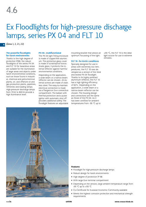
44.6The powerful floodlights for harsh environments Thanks to the high degree of protection IP66, the robust floodlights of the series PX 04 and FLT 10 for hazardous areas are suitable for the illumination of large areas and objects under harsh environmental conditions, such as those found in industri-al, chemical and petrochemical plants, on- and offshore oil and gas production plants, pipelines, refineries and loading ramps. High-pressure discharge lamps from 70 W to 600 W provide a high illuminance level.Ex Floodlights for high-pressure discharge lamps, series PX 04 and FLT 10(Zone 1, 2, 21, 22)Features• Floodlight for high-pressure discharge lamps • Robust design for harsh environments • High degree of protection IP 66• With large Ex-e terminal compartment• Depending on the version, large ambient temperature range from -55 °C up to +55 °C • CU-Certificate for Eurasian Economic Community available • Meets the highest corrosion protection and mechanical strength requirementsPX 04 - multifunctionalThe PX 04 light fitting enclosure is made of copper-free alumini-um. The protective glass cover is made of scratchproof boros-ilicate glass; it protects the in-ternal reflector against harmful environmental conditions.Depending on the application, a wide beam or a narrow beam reflector can be chosen. All ex-ternal screws are made of stain-less steel. The easy-to-maintain electrical connection is made via a flanged-on Ex-e connection compartment. The ballast with thermal protection and a pulse ignitor with automatic shut off provides additional safety. The floodlight features an adjustablemounting bracket that allows an optimum focussing of the light.FLT 10 - for Arctic conditions Specially designed for use in areas with extremely low tem-peratures, the FLT 10 was de-veloped as a version of the tried and tested PX 04 floodlight. Thanks to its highly polished aluminium reflector, the FLT 10 has a high lighting efficiency of 62%. Depending on the application, a wide beam or a narrow beam reflector can be chosen. The housing design and connections are the same as those of the PX 04. As it has been certified for ambient temperatures from -55 °C up to+55 °C, the FLT 10 is the ideal light source for use in extreme climates.44.6Ordering details PX 04 / FLT 10Ordering detailsT ypeContentLamp / IlluminantReflectorRatedluminous flux 1)WeightMetal threadThreaded plugOrder No.PX PX 0405-20 °C up to +55 °C IQT - 500 W narrow beam 10000 lm 23 kg 2 x M25 1 x M25 NOR 000 115 170 209PX 0405-20 °C up to +55 °C IQT 500 Wwide beam10000 lm 23 kg 2 x M25 1 x M25 NOR 000 115 170 309PX 0407-20 °C up to +55 °C HIT / HST 70 W narrow beam 5100/6000 lm 23 kg 2 x M25 1 x M25 NOR 000 115 170 230PX 0415-20 °C up to +55 °C HIT / HST 150 W narrow beam 11000/15000 lm 31 kg 2 x M25 1 x M25 NOR 000 115 170 233PX 0415-20 °C up to +55 °C HIT / HST 150 W wide beam 14000/15000 lm 31 kg 2 x M25 1 x M25 NOR 000 115 170 333PX 0425-20 °C up to +55 °C HIT / HST 250 W narrow beam 19000/28000 lm 31 kg 2 x M25 1 x M25 NOR 000 115 170 227PX 0425-20 °C up to +55 °C HIT / HST 250 W wide beam19000/28000 lm 31 kg 2 x M25 1 x M25 NOR 000 115 170 327PX 0440H -20 °C up to +55 °C HIT 400 W narrow beam 33000 lm 31 kg 2 x M25 1 x M25 NOR 000 115 170 222PX 0440H -20 °C up to +55 °C HIT 400 W wide beam 33000 lm 31 kg 2 x M25 1 x M25 NOR 000 115 170 322PX 0440S -20 °C up to +55 °C HST 400 W narrow beam 48000 lm 31 kg 2 x M25 1 x M25 NOR 000 115 170 221PX 0440S -20 °C up to +55 °C HST 400 W wide beam 48000 lm 31 kg 2 x M25 1 x M25 NOR 000 115 170 321PX 0460-20 °C up to +55 °C HST 600 W narrow beam 90000 lm 31 kg 2 x M25 1 x M25 NOR 000 115 170 215PX 0460-20 °C up to +55 °C HST 600 Wwide beam90000 lm 31 kg 2 x M25 1 x M25 NOR 000 115 170 315FLT FLT 1007-55°C up to +55 °C HIT / HST 70 W wide beam 5100/6000 lm 41 kg 2 x M25 1 x M25 FLT10 0 07271 W002FLT 1007-55°C up to +55 °C HIT / HST 70 W narrow beam 5100/6000 lm 41 kg 2 x M25 1 x M25 FLT10 0 07271 N002FLT 1010-55°C up to +55 °C HIT / HST 100 W wide beam 10000/9000 lm 41 kg 2 x M25 1 x M25 FLT10 0 10401 W002FLT 1010-55°C up to +55 °C HIT / HST 100 W narrow beam 10000/9000 lm 41 kg 2 x M25 1 x M25 FLT10 0 10401 N002FLT 1015-55°C up to +55 °C HIT / HST 150 W wide beam 11000/15000 lm 41 kg 2 x M25 1 x M25 FLT10 0 15401 W002FLT 1015-55°C up to +55 °C HIT / HST 150 W narrow beam 11000/15000 lm 41 kg 2 x M25 1 x M25 FLT10 0 15401 N002FLT 1025-55°C up to +55 °C HIT / HST 250 W wide beam 19000/28000 lm 41 kg 2 x M25 1 x M25 FLT10 0 25401 W002FLT 1025-55°C up to +55 °C HIT / HST 250 W narrow beam 19000/28000 lm 41 kg 2 x M25 1 x M25 FLT10 0 25401 N002FLT 1040-55°C up to +40 °C HIT 400 W wide beam 33000 lm 41 kg 2 x M25 1 x M25 FLT10 I 40401 W002FLT 1040-55°C up to +40 °C HIT 400 W narrow beam 33000 lm 41 kg 2 x M25 1 x M25 FLT10 I 40401 N002FLT 1040-55°C up to +40 °C HST 400 W wide beam 48000 lm 41 kg 2 x M25 1 x M25 FLT10 S 40401 W002FLT 1040-55°C up to +40 °C HST 400 Wnarrow beam48000 lm41 kg2 x M251 x M25FLT10 S 40401 N0021)depends on used lampsScope of delivery without lamp and fixing accessories, if not stated otherwise.Metal cable glands see catalogue part 2: 2.3.12 ffAccessoriesT ypeContentApplicationOUOrder No.SB 2 St pipe clamp Ø 48 mm up to Ø 64 mm incl. fixing screws PX 04 / FLT 101NOR 000 005 170 583ATP portable stand, painted steel PX 04 / FLT 10 ..1NOR 000 005 170 715 PAH horizontal steel shade, painted steel PX 04 / FLT 10 ..1NOR 000 005 170 608PAV vertical steel shade, painted steel PX 04 / FLT 10 ..1NOR 000 005 170 591HIT 250 W Metal halide lamp 250 W E40PX 04 / FLT 10 ..1CGS 323 7990 P1007HIT 400 W Metal halide lamp 400 W E40PX 04 / FLT 10 ..1CGS 323 7990 P1008HST 250 W High pressure sodium lamp 250 W E40PX 04 / FLT 10 ..1 3 2475 900 016HST 400 W High pressure sodium lamp 400 W E40PX 04 / FLT 10 ..13 2475 900 015HST 70 WHigh pressure sodium lamp 70 W E40PX 04 / FLT 103 1750 301 070Other lamps on request4Dimension drawing / Polar curvePX 04 / FLT 104.6without ballast for QT- and HME-SB-lampswith ballast for all high pressure discharge lampsoptional entry, on requestentryPX 04 and FLT 10Dimensions in mm44.6T echnical data PX 04 / FLT 10T echnical dataPX 04FLT 10EC-Type Examination Certificate BVS 09 ATEX E 050 X BVS 09 ATEX E 050 X IECEx Certificate of Conformity IECEx BVS-10.0009XIECEx BVS-10.0009XMarking accd. to 2014/34/EU D II 2G Ex d eb IIB T2-T4 1) GbD II 2D Ex tb IIIC T85°C-T210°C 1) Db D II 2G Ex de IIB T3-T4 1) GbD II 2D Ex tb IIIC T130°C-T190°C 1) Db Marking accd. to IECEx Ex de IIB T2-T4Ex tD A21 IP66 T85°C - 210°C Ex de IIB T3-T4Ex tD A21 IP66 T130°C - 190°C Permissible ambient temperature -20 °C up to +55 °C -55°C up to +55 °C Rated voltage without control gear ≤ 250 V AC --Rated voltage with control gear 230 V AC 230 V AC Frequency 50 Hz 50 Hz Power factor cos ϕ> 0.85> 0.85Circuit compensated circuit compensated circuit Protection class IILamp name High pressure sodium lamp HST, Metal halide lamp HIT High pressure sodium lamp HST, Metal halide lamp HITRated luminous flux 2)2)Lamp cap E40 accord. IEC 60238E40 accord. IEC 60238Light output ratio 62 %60 %Dimensions (L x W x H)546 x 443 x 396 mm 546 x 443 x 403 mm Connecting terminals (Ex-e)L1, N: 2 x 4 mm 2; PE: 2 x 6 mm 2L1, N: 2 x 4 mm 2; PE: 2 x 6 mm 2Enclosure earth 2 x 6 mm 2 2 x 6 mm 2Enclosure colour grey grey Enclosure material Light alloy Light alloy Weight31 kg41 kgCable glands / gland plates / enclosure drilling Indirect entries (Ex-e): 2 x M25 x 1.5 thread 1 x plugged M25 screw plug Indirect entries (Ex-e): 2 x M25 x 1.5 thread 1 x plugged M25 screw plug Type of mountingceiling mounting ceiling mounting Degree of protection accd. to EN 60529IP66IP66Protective cover / protective bowl borosilicate glass borosilicate glass Reflectorpolished aluminium reflectorpolished aluminium reflector1) see table page 1.4.362)see table luminaire data S. 1.4.36Technical dataPX 04 / FLT 1044.6Additional luminaire data PX 04T emperature class II 2 Gmax. surface temp. II 2 D LampPowerRated luminous flux 1)T U ≤ 40 °C T U ≤ 55 °CT U ≤ 40 °CT U ≤ 55 °CPX 0407HS - 70 W 6000 lm T4T4T85 °C T100 °C PX 0407HI. - 70 W 5100 lm T4T4T90 °C T105 °C PX 0415HS. - 150 W 15000 lm T4T4T115 °C T130 °C PX 0415HI. - 150 W 11000 lm T4T4T105 °C T120 °C PX 0425HS. - 250 W 28000 lm T4T3T130 °C T145 °C PX 0425HI. - 250 W 19000 lm T4T3T130 °C T145 °C PX 0440HST - 400 W 48000 lm T3T3T175 °C T190 °C PX 0440HIT - 400 W 33000 lm T3T3T170 °C T185 °C PX 0460HST - 600 W 90000 lm T3T2T195 °C T210 °C PX 0405IQT - 500 W10000 lmT3T2T185 °CT200 °C1)depends on used lampsAdditional luminaire data FLT 10T emperature class II 2 Gmax. surface temp. II 2 D LampPowerrated luminous flux 1)T U ≤ 40 °CT U ≤ 55 °CT U ≤ 40 °CT U ≤ 55 °CFLT 1007HS - 70 W 6000 lm T4T4T115 °C T130 °C FLT 1007HI. - 70 W 5100 lm T4T4T115 °C T130 °C FLT 1015HS. - 150 W 15000 lm T4T4T115 °C T130 °C FLT 1015HI. - 150 W 11000 lm T4T4T115 °C T130 °C FLT 1025HS. - 250 W 28000 lm T4T3T145 °C T160 °C FLT 1025HI. - 250 W 19000 lm T4T3T145 °C T160 °C FLT 1040HST - 400 W 48000 lm T3 --T190 °C --FLT 1040HIT - 400 W33000 lmT3--T190 °C--1)depends on used lamps。
Flex10UHT培训
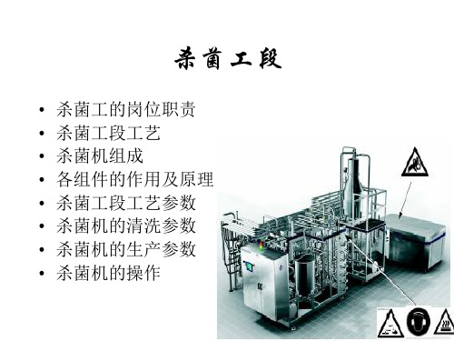
一、开机前检查: 检查蒸汽压力是否达到0.6Mpa ,检查冷却水压力是否达到0.3Mpa 检查压缩空气的压力是否达到0.6Mpa ,检查管路连接是否与所生产产品符合 检查仪表显示是否正确 ,检查各开关是否打到自动位置 检查紧急停机开关是否释放 ,检查报紧系统是否灵敏 二、开机 选择与生产产品相符的生产键位 ,选择与灌装机相符的生产键位 视产品品种选择脱气罐和冷却装置 ,严格按先后顺序加热消毒、冷却、无菌水 循环 ,进料生产并按动相应键位 三、生产运行 生产出现报警时,应立即查找原因排除故障,不可在存有故障的前提下生产 严格按自动操作程序进行操作,不可强行施加命令 四、清洗 严格按要求配制清洗液 ,生产必须选择清洗程序 严格按自动清洗程序清洗,不允许强行施加命令,清洗后酸、碱浓度要达到要求 五、停机 清洗设备将自动停机 ,关掉显示屏电源开关 如特殊情况应先关蒸汽紧急制动阀,后按停车键 六、阀或泵的有关说明: V74、V78:倍压阀,V74减压阀,V78增压阀 M6物料泵,要想增加M6值, 可调节V62 M2物料泵 M9热水泵 V44:蒸汽阀
杀菌机的清洗参数
• • • • • • • • • • • • • • • • CIP清洗 1、进碱 浓度30-33% 量≥50L 时间370秒 第113步 2、碱循环 在139℃高温下进行 时间50分 第114步 3、排碱 第115步 4、用水冲 时间10分 第121步 5、进酸 浓度35±2% 量≥25L 时间200秒 第124步 6、酸循环 在100-110℃下进行 时间20分 第125步 7、排酸 第126步 8、用90℃热水冲洗8分钟 第146步 9、降温(测PH 值显中性) 第147步 AIC清洗 1、进碱 370秒 浓度30-33% 第50步 2、碱循环 50分钟 第51步 3、排碱 第52步 4、水冲 第53步 不降温直接到无菌水循环
全氟辛烷磺酸

环境科学家们根据目前的初步调查结果,认为PFOS已成 为继多氯联苯、有机氯浓烟、二恶英等之后的POPs,PFOS 的环境污染物以及对整个生态系统和人类健康的影响研究,将 成为今后环境科学和预防医学领域的研究热点。 到目前为止,有关PFOS的污染来源、环境中迁移转化的 规律、受污染环境的修复方法以及包括人类在内的生物体内 PFOS污染水平及其潜在的长期危险性还没有研究清楚,针对 不同浓度水平的PFOS的标准定量检测方法还未得到建立,这 些都是亟待解决的问题。只有相关领域内研究者的共同努力与 协作,才能早日实现PFOS的减排目标,降低全氟类化合物的 污染程度,保持生态平衡,切实维护人类的饮水与食品安全。
2002年12月,经合组织(OECD)召开的第34次化学 品委员会联合会议上将PFOS定义为持久存在于环境、具 有生物储蓄性并对人类有害的物质。 欧委会于2005年12月5日提出了关于限制全氟辛烷磺 酸销售及使用的建议和指令草案,并对该建议实施的成本 、益处、平衡性、合法性等方面进行了评估。2006年10 月30日,欧洲议会以632票比10票通过了该草案一读, 2006年12月12日指令草案最终获得部长理事会批准, 2006年12月27日指令正式公布并同时成效。 2006年12月27日,欧洲议会和部长理事会联合发布 《关于限制全氟辛烷磺酸销售及使用的指令》( 2006/122/EC),该指令是对理事会《关于统一各成员国 有关限制销售和使用禁止危险材料及制品的法律法规和管 理条例的指令》(76/769/EEC)的第三十次修订。根据 规定,该指令于2008年6月27日开始生效。
目录
前言 一. 介绍
1.1 PFOS之发展历程 1.2 基本性质 1.3 主要用途
二. 超级“杀手”
2.1 对人体的危害 2.2 水体PFOS污染 2.3 沉积物PFOS污染 2.4 无处不在的PFOS
- 1、下载文档前请自行甄别文档内容的完整性,平台不提供额外的编辑、内容补充、找答案等附加服务。
- 2、"仅部分预览"的文档,不可在线预览部分如存在完整性等问题,可反馈申请退款(可完整预览的文档不适用该条件!)。
- 3、如文档侵犯您的权益,请联系客服反馈,我们会尽快为您处理(人工客服工作时间:9:00-18:30)。
101/102 PHR-STVishay BCcomponentsAluminum CapacitorsPower High Ripple Current Screw TerminalsFEATURES•Polarized aluminum electrolytic capacitors,non-solid electrolyte•Large types, cylindrical aluminum case,insulated with a blue sleeve •Pressure relief in the sealing •Long useful lifeAPPLICATIONS•Computer, telecommunications and industrial systems•Smoothing and filtering•Standard and switched mode power suppliesMARKINGThe capacitors are marked with the following information:•Rated capacitance (in µF)•Tolerance on rated capacitance, code letter in accordance with IEC 60062 (M for ± 20 %)•Rated voltage (in V)•Date code (YYMM)•Name of manufacturer •Code for factory of origin•'-' sign to identify the negative terminal, visible from the top and side of the capacitor •Code number•Climatic category in accordance with IEC60068Fig.1 Component outlineQUICK REFERENCE DATADESCRIPTIONVALUE101102Nominal case size (∅ D ×L in mm)35×60to 76×146Rated capacitance range (E6 series), C R 220to 330000µF T olerance on C R± 20 %Rated voltage range, U R25 to100 V 200to 450VCategory temperature range - 40to + 85 °C Endurance test at 85 °C 2000hoursUseful life at 85 °C10000hours (D ≤ 50 mm)15000 hours (D ≥ 65 mm)10000hours Useful life at 40 °C, 1.4 x I R applied400000hours (D ≤ 50 mm)600000 hours (D ≥ 65 mm)400000hours Shelf life at 0V, 85 °C500hoursBased on sectional specification IEC 60 384-4/EN130300Climatic category IEC 6006840/085/56SELECTION CHART FOR C R , U R AND RELEVANT NOMINAL CASE SIZES (Ø D ×L in mm)C R (µF)UR (V)254063100200250350385400450220-------35 x 6035 x 6035 x 60330------35 x 60-35 x 60--------35 x 8035 x 8035 x 80470-----35 x 60-35 x 8035 x 80-------35 x 80-35 x 10535 x 105680----35 x 6035 x 80-35 x 10535 x 105-------35 x 105-50 x 8050 x 801000----35 x 8035 x 80-50 x 8050 x 8050 x 80----35 x 10535 x 10550 x 80-50 x 10550 x 1051500----35 x 10535 x 105---50 x 105----50 x 8050 x 8050 x 10550 x 10550 x 10565 x 1052200---35 x 6050 x 8050 x 8050 x 105--65 x 105-----50 x 10565 x 10565 x 10565 x 105-3300---35 x 6050 x 8050 x 105--65 x 10576 x 105---35 x 8050 x 10565 x 10565 x 10576 x 105-76 x 1464700--35 x 6035 x 80-65 x 10576 x 10576 x 10576 x 10576 x 146---35 x 10565 x 10576 x 10576 x 14676 x 14676 x 146-5600---------76x 146Document Number: 28371For technical questions contact: aluminumcaps2@101/102 PHR-STAluminum Capacitors Power High Ripple Current Screw TerminalsVishay BCcomponents6800--35 x 6035 x 10565 x 10576 x 105--76 x 146---35 x 8050 x 8076 x 10576 x 14676 x 14676 x 146--10000-35 x 6035 x 8050 x 8076 x 10576 x 105------35 x 10550 x 10576 x 14676 x 146----1500035 x 6035 x 6035 x 10550 x 10576 x 146------35 x 8050 x 80-------2200035 x 6035 x 8050 x 8065 x 105-------50 x 8050 x 10576 x 105------3300035 x 8035 x 10550 x 10576 x 105------50 x 8050 x 8065 x 10576 x 146------4700035 x 10550 x 8065 x 105-------50 x 8050 x 10576 x 10576 x 146------6800050 x 8050 x 10565 x 105-------50 x 10565 x 10576 x 146-------10000050 x 10565 x 105--------65 x 10576 x 10576 x 146-------15000065 x 10576 x 105--------76 x 10576 x 146--------22000065 x 105---------76 x 10576 x 146--------33000076 x 146---------SELECTION CHART FOR C R , U R AND RELEVANT NOMINAL CASE SIZES (Ø D ×L in mm)C R (µF)U R (V)254063100200250350385400450DIMENSIONS in millimeters AND AVAILABLE FORMSMaximum permissible torque which may be applied to the termination screws: 2Nm.For accessories refer to datasheet “Mounting Accessories”.The capacitors are delivered with screws and washers.Fig.2 Screw terminal (ST); screw terminal bolt (STB)Table 1* Terminals also available in High Current version. Contact manufacturer for mechanical dimensions.DIMENSIONS in millimeters, MASS AND PACKAGING QUANTITIESNOMINAL CASE SIZE ∅ D ×L ∅ D max L max P ± 0.3 A ± 0.5d 1 ± 0.2T ± 0.5d 2×l MASS (g)PACKAGING QUANTITIES (per box)CAR DBOAR D BOX DIMENSIONS L ×W ×H 35×6036631388 5.9M8×127525196×192×11035×8036811388 5.9M8×129525196×192×11535×105361051388 5.9M8×1213025196×192×14050×8051.58322128 5.9M12×1620025293×273×11550×10551.510522128 5.9M12×1630025293×273×14065×1056610528.5168* 5.9*M12×1648010368×151×14076×1057710632198* 5.9*M12×1670010418×173×14076×1467714632198*5.9*M12×16100010418×173×180101/102 PHR-STVishay BCcomponents Aluminum CapacitorsPower High Ripple Current Screw TerminalsNote1.Unless otherwise specified, all electrical values in T ables 2 and3 apply at T amb=20°C, P=86to106kPa, RH=45to75 %.ORDERING EXAMPLE Electrolytic capacitor 101 series 10000µF/40V; ± 20 %Nominal case size: ∅ 35×60mm; ST version, high post M5 disc Catalog number: 222210117103.ELECTRICAL DATASYMBOL DESCRIPTIONC R rated capacitance at 100Hz, tolerance ± 20 %I R rated RMS ripple current at 100Hz, 85 °CI L5max. leakage current after 5minutes at U RESR max. equivalent series resistance at 100HzZ max. impedance at 20 kHzTable 2ELECTRICAL DATA AND ORDERING INFORMATION FOR 101 SERIESU R (V)C R100Hz(µF)NOMINALCASE SIZE∅ D×L(mm)I R100Hz85°C(A)I L55min(mA)ESR max100Hz(mΩ)ZMAX.20kHz(mΩ)HIGH POST M5 DISCCATALOGNUMBER ST2222 101 .....CATALOGNUMBER STB2222 101 .....251500035 x 607.70.7529221615356153 2200035 x 608.3 1.10272216223562233300035 x 809.0 1.65191716333563333300050 x 8010.0 1.65171426333663334700035 x 10512.1 2.35151316473564734700050 x 8014.8 2.35121026473664736800050 x 8012.8 3.40151316683566836800050 x 10517.1 3.4098266836668310000050 x 10514.7 5.001211161045610410000065 x 10519.6 5.0076261046610415000065 x 10517.67.5087161545615415000076 x 10521.47.5065261546615422000065 x 10520.211.0065162245622422000076 x 10522.511.0065262246622433000076 x 14625.816.50442633466334 401000035 x 607.10.8031231710357103 1500035 x 607.8 1.20282217153571531500035 x 808.7 1.20221727153671532200035 x 809.4 1.76201717223572232200050 x 8011.2 1.76191527223672233300035 x 10511.0 2.64151317333573333300050 x 8013.7 2.64131027333673334700050 x 8014.6 3.76121017473574734700050 x 10515.9 3.7610827473674736800050 x 10516.9 5.449817683576836800065 x 10518.1 5.4476276836768310000065 x 10519.28.0076171045710410000076 x 10521.38.0076271046710415000076 x 10520.512.0076171545715415000076 x 14624.012.0055271546715422000076 x 14624.517.60552722467224 For technical questions contact: aluminumcaps2@ Document Number: 28371Document Number: 28371For technical questions contact: aluminumcaps2@101/102 PHR-STAluminum Capacitors Power High Ripple Current Screw TerminalsVishay BCcomponents63470035 x 60 5.90.5942251847258472680035 x 60 6.60.8638251868258682680035 x 807.30.86301928682686821000035 x 808.1 1.26271918103581031000035 x 1058.8 1.26221428103681031500035 x 1059.7 1.89191418153581531500050 x 8012.1 1.89161128153681532200050 x 8011.1 2.77191518223582232200050 x 10514.3 2.7712928223682233300050 x 10512.9 4.16141218333583333300065 x 10516.5 4.169628333683334700065 x 10515.6 5.9210818473584734700076 x 10518.6 5.928628473684736800076 x 10520.08.577618683586836800076 x 14621.98.5765286836868310000076 x 14623.412.60552810468104100220035 x 60 5.20.4450291922259222330035 x 60 6.00.6642271933259332330035 x 80 6.60.6635212933269332470035 x 807.30.9431201947259472470035 x 1057.90.9426162947269472680035 x 1058.8 1.3623151968259682680050 x 8010.9 1.36191229682696821000050 x 8010.5 2.00211519103591031000050 x 10513.1 2.0014929103691031500050 x 10512.3 3.00161219153591532200065 x 10514.8 4.4011819223592232200076 x 10517.4 4.409629223692233300076 x 10519.0 6.608619333593333300076 x 14620.7 6.607529333693334700076 x 14622.49.40652947369473ELECTRICAL DATA AND ORDERING INFORMATION FOR 101 SERIESU R (V)C R 100Hz (µF)NOMINAL CASE SIZE ∅ D ×L (mm)I R 100Hz 85°C (A)I L55min (mA)ESR max 100Hz (m Ω)Z MAX.20kHz (m Ω)HIGH POST M5 DISC CATALOG NUMBER ST 2222 101 .....CATALOG NUMBER STB 2222 101 .....101/102 PHR-STVishay BCcomponents Aluminum CapacitorsPower High Ripple Current Screw TerminalsTable 3ELECTRICAL DATA AND ORDERING INFORMATION FOR 102 SERIESU R (V)C R100Hz(µF)NOMINALCASE SIZE∅ D×L(mm)I R100Hz85°C(A)I L55min(mA)ESR max100Hz(mΩ)ZMAX.20kHz(mΩ)HIGH POST M5 DISCCATALOGNUMBER ST2222 102 .....CATALOGNUMBER STB2222 102 .....20068035 x 60 3.50.272071361268152681 100035 x 80 4.40.40144951210252102100035 x 105 4.70.40140912210262102150035 x 105 5.50.60100671215252152150050 x 80 6.20.60106742215262152220050 x 808.00.8867441222252222330050 x 808.9 1.3250351233252332330050 x 1059.9 1.3246322233262332470065 x 10512.5 1.8837262247262472680065 x 10515.2 2.7225181268252682680076 x 10516.9 2.72251822682626821000076 x 10519.9 4.00181312103521031000076 x 14620.4 4.00181322103621031500076 x 14624.1 6.001291215352153 25047035 x 60 3.10.242501521347153471 68035 x 80 3.80.341751071368153681100035 x 80 4.40.50128821310253102100035 x 105 4.80.50122762310263102150035 x 105 5.40.7590581315253152150050 x 807.00.7581502315263152220050 x 808.0 1.1060391322253222220050 x 1058.7 1.1057352322263222330050 x 1059.8 1.6542281333253332330065 x 10511.4 1.6542282333263332470065 x 10513.8 2.3529191347253472470076 x 10515.3 2.3529192347263472680076 x 10518.1 3.4021141368253682680076 x 14618.6 3.40211423682636821000076 x 10519.3 5.00171213103531031000076 x 14622.0 5.0015102310363103 35033035 x 60 2.50.234353051533155331 47035 x 80 3.10.33308216254716547168035 x 105 3.80.482161522568165681100050 x 80 5.60.701451022510265102150050 x 80 6.5 1.05102741515255152150050 x 1057.0 1.0599702515265152220050 x 1058.0 1.5472521522255222220065 x 1059.3 1.5472522522265222330065 x 10511.4 2.3148352533265332470076 x 10515.0 3.2934251547255472470076 x 14615.4 3.2934252547265472680076 x 14618.3 4.7624182568265682 For technical questions contact: aluminumcaps2@ Document Number: 28371Document Number: 28371For technical questions contact: aluminumcaps2@101/102 PHR-STAluminum Capacitors Power High Ripple Current Screw TerminalsVishay BCcomponents38522035 x 60 2.10.17575380182215822133035 x 80 2.70.26386257183315833147035 x 80 3.10.37279188184715847168035 x 105 3.90.531961331868158681100050 x 80 5.60.77132891810258102150050 x 1057.1 1.1690611815258152220065 x 10510.0 1.7061421822258222330076 x 10513.4 2.5542291833258332470076 x 10515.0 3.6231221847258472470076 x 14616.3 3.6229202847268472680076 x 14618.3 5.242216186825868240022035 x 60 2.10.18557363162215622133035 x 60 2.50.26383254163315633133035 x 80 2.70.26374245263316633147035 x 80 3.10.38271180164715647147035 x 105 3.30.38265175264716647168035 x 105 3.90.55191128166815668168050 x 80 4.50.541991362668166681100050 x 80 5.70.80128861610256102100050 x 105 6.00.80125832610266102150050 x 1057.1 1.2088592615266152220065 x 10510.0 1.7660402622266222330065 x 10512.1 2.6440271633256332330076 x 10513.4 2.6440272633266332470076 x 10515.0 3.7631211647256472470076 x 14616.4 3.7628192647266472680076 x 14618.3 5.442215266826668245022035 x 60 2.10.20503313172215722133035 x 80 2.70.30339212273316733147035 x 105 3.40.42241151274716747168050 x 80 4.90.61159982768167681100050 x 80 5.70.90118751710257102100050 x 105 6.10.90114722710267102150050 x 1057.1 1.3581521715257152150065 x 1058.3 1.3581522715267152220065 x 10510.1 1.9855351722257222220076 x 10511.2 1.9855352722267222330076 x 10513.5 2.9737241733257332330076 x 14613.9 2.9737242733267332470076 x 14616.4 4.2326171747257472560076 x 14617.35.0423151756257562ELECTRICAL DATA AND ORDERING INFORMATION FOR 102 SERIESU R (V)C R 100Hz (µF)NOMINAL CASE SIZE ∅ D ×L (mm)I R 100Hz 85°C (A)I L55min (mA)ESR max 100Hz (m Ω)Z MAX.20kHz (m Ω)HIGH POST M5 DISC CATALOG NUMBER ST 2222 102 .....CATALOG NUMBER STB 2222 102 ..... For technical questions contact: aluminumcaps2@Document Number: 28371101/102 PHR-STVishay BCcomponentsAluminum CapacitorsPower High Ripple Current Screw TerminalsADDITIONAL ELECTRICAL DATAPARAMETERCONDITIONSVALUEVoltageSurge voltage ≤ 250V versions U s =1.15×U R ≥ 350V versionsU s =1.1×U R Reverse voltage U rev ≤1VCurrentLeakage current in µAafter 1minute at U R I L1≤0.006 C R ×U R after 5minutes at U R I L5≤0.002 C R ×U R InductanceEquivalent series inductance (ESL)case ∅ D =35mm typ. 13nH case ∅ D =50mm typ. 16nH case ∅ D =65mm typ. 19nH case ∅ D =76mmtyp. 20nHRIPPLE CURRENT AND USEFUL LIFE54.543.532.521.510.511.11.21.31.41.5air velocity [m/s]I R forced I R freeFig.3 Multiplier of ripple current (Ir) as a function of air flowNoteCalculation example for 102 series. Maximum ripple current multiplier = 1.6 x 1.3 x 1.25 = 2.6MAXIMUM RIPPLE CURRENTPARAMETER CONDITIONMAXIMUM RIPPLE CURRENT MULTIPLIERVALUE Ambient temperature (T amb )70 °C from nomogram; see fig. 4 1.6Operating frequency (f)400 Hz from frequency ; table 4 1.3Air flow2 m/sfrom air-flow; see fig. 31.25Document Number: 28371For technical questions contact: aluminumcaps2@101/102 PHR-STAluminum Capacitors Power High Ripple Current Screw TerminalsVishay BCcomponentsI A =actual ripple current at 100HzI R =rated ripple current at 100Hz and 85°C(1)Useful life at 85°C and I R applied:101 series: case Ø D ≤ 50: 10000 hours case Ø D ≥ 65: 15000 hours 102 series: 10000 hoursFig.4 Multiplier of useful life as a function of ambient temperature and ripple current loadTable 4MULTIPLIER OF RIPPLE CURRENT (I R ) AS A FUNCTION OF FREQUENCYFREQUENCY (Hz)I R MULTIPLIER101102500.850.90100 1.00 1.00200 1.10 1.20400 1.15 1.301000 1.20 1.40100001.301.50101/102 PHR-STVishay BCcomponents Aluminum CapacitorsPower High Ripple Current Screw TerminalsTable 5TEST PROCEDURES AND REQUIREMENTSTEST PROCEDURE(quick reference)REQUIREMENTSNAME OF TEST REFERENCEEndurance IEC60384-4/EN130300subclause 4.13T amb=85°C; U R applied;2000hoursU R≤100V; ΔC/C:±15 %U R>100V; ΔC/C:±10 %tanδ≤1.3×spec. limitZ≤2×spec. limitI L5≤spec. limitUseful life CECC30301subclause 1.8.1T amb=85°C; U R and I R applied;101 series: case Ø D ≤ 50:10000hourscase Ø D ≥ 65:15000hours102 series: 10000 hoursU R≤100V; ΔC/C:± 45 %U R>100V; ΔC/C:±30 %tanδ≤3×spec. limitZ≤3× spec. limitI L5≤spec. limitno short or open circuit,no visible damagetotal failure percentage:U R ≤100V: ≤ 1 %;U R >100V: ≤ 3 %Shelf life (storage athigh temperature)IEC60384-4/EN130300subclause 4.17T amb=85°C; no voltage applied;500hoursafter test: U R to be applied for 30minutes,24to48hours before measurementΔC/C:± 10 %tanδ≤1.2×spec. limitI L5≤2× spec. limit For technical questions contact: aluminumcaps2@ Document Number: 28371Legal Disclaimer NoticeVishayNoticeSpecifications of the products displayed herein are subject to change without notice. Vishay Intertechnology, Inc., or anyone on its behalf, assumes no responsibility or liability for any errors or inaccuracies.Information contained herein is intended to provide a product description only. No license, express or implied, by estoppel or otherwise, to any intellectual property rights is granted by this document. Except as provided in Vishay's terms and conditions of sale for such products, Vishay assumes no liability whatsoever, and disclaims any express or implied warranty, relating to sale and/or use of Vishay products including liability or warranties relating to fitness for a particular purpose, merchantability, or infringement of any patent, copyright, or other intellectual property right. The products shown herein are not designed for use in medical, life-saving, or life-sustaining applications. Customers using or selling these products for use in such applications do so at their own risk and agree to fully indemnify Vishay for any damages resulting from such improper use or sale.。