热处理对Al/Fe双金属复合材料结合层中间相生长规律的影响
过热处理对Al―Si过共晶合金耐磨性能的影响
过热处理对Al―Si过共晶合金耐磨性能的影响
过热处理对Al-Si过共晶合金的耐磨性能有重要影响,下面就
详细介绍一下它的影响。
首先,过热处理可以改善Al-Si过共晶合金的组织和晶格变形,使其具有更好的耐磨性能。
这是由于过热处理过程中高温所产生的热应力和塑性应变可以改善铸件内部的晶粒分布和高温热稳定性,从而使其具有更佳的耐磨性能。
此外,过热处理还能够消除过共晶合金的内部缺陷,提高其韧性和强度,进一步增强其耐磨性能。
其次,过热处理还能改善Al-Si过共晶合金表面的化学成分和
结构组成,使其具有更好的耐磨性能。
这是由于过热处理能够使表面金属碱度提高,减少自由Si相含量,改善表面的化学
成分组成,进而提高铸件对耐磨材料的耐损耗性能。
同时,过热处理还能促进表面结构的变化,使得铸件表面形成一层薄膜,进一步增加了铸件表面的硬度和耐磨性能。
最后,过热处理还能调整Al-Si过共晶合金的熔化温度,进一
步改善合金成分和晶格结构。
这是由于过热处理可以提高Al-
Si过共晶合金的熔化温度,改变合金成分的结构和晶格配置,提高其崩裂韧性和抗疲劳性能,进一步增强其耐磨性能。
总之,过热处理对Al-Si过共晶合金的耐磨性能有较大的影响,能够改善其组织和晶格变形,消除内部缺陷,促进表面化学成分和结构的变化,调整合金熔化温度等因素,从而使其具有更佳的耐磨性能。
热处理对金属材料的晶界稀土分布的影响

热处理对金属材料的晶界稀土分布的影响热处理是一种常见的金属加工方法,通过控制金属材料的温度和时间,在晶界结构上产生显著的影响。
而在金属材料中,稀土元素的存在对晶界分布具有重要的影响。
本文将重点探讨热处理对金属材料的晶界稀土分布的影响。
影响一:晶界的化学成分变化在热处理过程中,金属材料的晶界会发生化学成分的变化。
稀土元素作为合金中的重要成分,其在晶界的分布态势也随之改变。
具体到不同的热处理方法,其对晶界稀土分布的影响也有所差异。
1. 固溶处理固溶处理是常用的热处理方法之一。
在固溶处理中,通过高温加热和快速冷却,使稀土元素与金属基体发生固溶反应。
结果显示,在晶界上形成更为均匀的稀土分布。
稀土元素的固溶度提高,从而增强了金属材料的强度和韧性。
2. 淬火处理与固溶处理不同,淬火处理通过将金属材料迅速冷却至室温,使晶界处的稀土元素发生析出作用。
在淬火处理过程中,稀土元素顺着晶界向晶体内部聚集,形成片状或点状的析出物。
这些析出物在晶界上形成了显著的稀土分布差异。
影响二:晶界对晶体生长的影响金属材料在热处理过程中,晶界的分布对晶体的生长过程起着重要的调控作用。
而稀土元素的存在则会对晶界的晶体生长产生一定的影响。
1. 晶界阻挡效应稀土元素可以阻碍晶界上新晶粒的生长,减缓了晶体的晶化速度。
这是因为稀土元素在晶界处形成了一层屏障,阻止了晶体生长时溶质的进入。
因此,稀土元素的分布会对晶界的晶体生长过程产生明显的影响。
2. 晶界扩散速率的改变稀土元素的存在可以改变晶界的扩散速率。
研究发现,稀土元素可以促进晶界处的溶质扩散速度,从而影响晶体的生长。
例如,稀土元素的加入可以降低溶质在晶界上的迁移能垒,加快了晶体晶界的扩散速率。
综上所述,热处理对金属材料的晶界稀土分布产生了显著影响。
在不同的热处理方法下,稀土元素的分布形态也会有所不同。
在固溶处理下,稀土元素在晶界形成均匀的分布;而在淬火处理下,稀土元素会形成片状或点状的析出物。
热处理对铝合金力学性能的作用机制研究

热处理对铝合金力学性能的作用机制研究
陶治颖
(合肥工业大学材料科学与工程学院,安徽 合肥 230000)
摘 要 :近年来,我国工业制造水平的不断提升,使铝合金成为工业制造业的重要原材料,铝合金的力学性能更是直接
影响到工业制造产品的整体质量。对于铝合金来说,其在加工过程中的溶处理对铝合金力学性能的作用机制
试验结果表明,铝合金试样的力学性能及组织结构会在 很大程度上受到固溶处理温度的影响,通过观察不同固溶处 理温度下,铝合金试样在硬度及力学性能上的变化曲线可以 发现,固溶处理温度的不断升高,会使 7075 铝合金的力学 性能在抗拉、硬度以及屈服强度上分别出现先增后降趋势, 当固溶处理温度达到 470℃时,此时铝合金的抗拉、屈服以 及 硬 度 也 达 到 了 一 个 峰 值,分 别 是 625MPa、550MPa 和 46.5HRB。
铝合金凭借其低密度、高韧、高强的优良性能,使其被 广泛应用于交通运输、航天航空、建筑业等多个领域。由于 铝合金中掺入了较高含量的 Zn、Mg 等元素,这使得铝合金 在热处理工艺中未得以充分固溶时,这些元素的存在很容易 影响到铝合金的综合性能,而且 Zn、Mg 元素的含量过高, 还会对铝合金造成严重的应力腐蚀问题,这势必会大幅降低 铝合金的结构强度。
为了解决上述问题,本文便以热处理工艺作为出发点, 深入研究热处理对铝合金力学性能的作用机制,以期能够为 铝合金的应用提供可靠的技术依据。
1 研究材料及方法 1.1 材料
本文将 7075 铝合金作为研究材料,该铝合金材料预先 已经进行了均匀化的退火处理,其内部化学元素的主要成分 包括 Zn、Mg、Cu、Mn、Fe、Si、Cr、Ti 以及 AL, 这些化学 元素的含量分别为 6.5%、2.2%、1.5%、0.6%、0.5%、0.5%、 0.15% 以及 0.1%。 1.2 热处理工艺
不同退火温度下复合带的金属间化合物的变化

不同退火温度下Ni/Al层状复合带的金属间化合物的变化余琨,宋觉敏,(中南大学材料科学与工程学院,长沙410083)摘要:Ni/Al层状复合带作为广泛应用于电池中的电子封装材料,需要较好的结合性能,这些结合性能与金属间化合物有很大的关系。
探讨了在不同退火温度下,Ni/Al复合带的复合界面上金属间化合物生长情况。
结果表明:1)当达到一定的热力学条件后,金属间化合物首先在界面局部区域生成并迅速完成长大,然后化合物新生相沿界面连接为一个整体。
2)金属间化合物层随温度升高而变厚。
3)退火过程中过高温度会使复合界面上生成较厚的脆性化合物。
关键词:退火温度,Ni/Al复合带,金属间化合物Intermetallic Compounds’ Change of the Ni/Al Clad Composite Strip In the Different Annealing TemperatureYu Kun,Song Jue-min(School of Materials Science and Engineering,Central South University,Changsha 410083,China)Abstract: Al/Ni clad composite strip is widely applied as aelectronic packaging materials in the battery. It needs high bonding strengthand that is consanguineously relative to intermetallic compound. The growth of intermetallics on the composite interface in Ni/Alcladding strip was studied in the different annealing temperature. The results shou that: 1) The intermetallics firstly form and grow rapidly in certian zones on the interface under proper thermodynamics conditions and then the intermetallics is jointed to a whole layer. 2)The intermetallic layer thickens with temperature rise. 3) brittleness compound was generated on the interface because of high tempurature in the annealing.Key: Annealing Temperature,Ni/Al Composite Strip,Intermetallic CompoundNi/Al层状复合带作为广泛应用于电池中的电子封装材料,主要用于铝壳手机电池重要的零部件原料。
层间冷加工和热处理对增材制造铝合金中孔隙的影响和孔隙闭合机制

层间冷加工和热处理对增材制造铝合金中孔隙的影响和孔隙闭合机制1.引言1.1 概述铝合金的增材制造是一种先进的制造技术,其在航空航天、汽车制造和船舶建造等领域具有广泛应用前景。
然而,增材制造过程中铝合金中的孔隙问题一直是制约其应用的重要因素。
孔隙的存在会降低材料的强度和韧性,从而影响零部件的性能和可靠性。
为了解决这一问题,研究人员提出了层间冷加工和热处理的方法,以改善铝合金中孔隙的形成情况和分布。
层间冷加工通过对每一层的熔化池进行控制,使其得到均匀的冷却和凝固,从而减少孔隙的形成。
而层间热处理则通过加热已凝固的层间界面区域,促使孔隙发生收缩和闭合,提高材料的密实性和结构强度。
本文将详细探讨层间冷加工和热处理对增材制造铝合金中孔隙的影响及其闭合机制。
首先,我们将介绍铝合金增材制造中存在孔隙问题的背景和原因,以便更好地理解孔隙形成的机制。
然后,我们将分析层间冷加工和热处理对孔隙形成的影响因素,包括加工参数、材料性质等方面。
通过对这些影响因素的研究,我们可以了解层间冷加工和热处理对孔隙形成的机理,并提出相应的改进措施。
最后,在结论部分,我们将总结影响层间冷加工和热处理对孔隙形成的因素,并给出相应的建议。
同时,我们还将总结目前对孔隙闭合机制的研究结果,探讨可能的理论模型和实验方法,为未来的研究提供参考。
通过对层间冷加工和热处理的研究,我们有望解决铝合金增材制造中孔隙问题,提高零部件的性能和可靠性,推动增材制造技术的发展。
1.2文章结构文章结构部分的内容可以根据实际情况进行编写,以下是一个示例:1.2 文章结构本文主要研究层间冷加工和热处理对增材制造铝合金中孔隙的影响以及孔隙闭合机制。
为了便于读者理解,本文按照以下结构进行组织和阐述:第2节为正文部分,主要分为两个小节。
第2.1节将详细探讨层间冷加工对增材制造铝合金中孔隙的影响,并介绍背景知识和相关影响因素。
第2.2节则会着重讨论层间热处理对增材制造铝合金中孔隙的影响,并介绍相关背景知识和影响因素。
形变与热处理对NiCrAlFe合金组织及性能的影响

形变与热处理对NiCrAlFe合金组织及性能的影响形变与热处理对NiCrAlFe合金组织及性能的影响摘要:NiCrAlFe合金因其优异的高温性能被广泛应用于航空航天和能源等领域。
本文通过对NiCrAlFe合金进行形变和热处理的研究,探讨了形变和热处理对其组织和性能的影响。
研究结果表明,形变和热处理能够显著改变NiCrAlFe合金的晶粒尺寸和相组成,并且对其力学性能和耐热性能具有重要影响。
形变可以细化晶粒并提高材料的强度,而热处理则可以改善显微组织的稳定性和提高材料的高温强度和耐氧化性能。
因此,形变和热处理在优化NiCrAlFe合金的组织和性能方面具有重要意义。
关键词:形变;热处理;NiCrAlFe合金;组织;性能1. 引言NiCrAlFe合金是一种具有优异高温性能的金属材料,因此被广泛应用于航空航天、能源和石油化工等领域。
在高温环境下,NiCrAlFe合金能够保持较高的强度和良好的耐热性能,且具有较好的抗氧化和抗腐蚀性能。
为了进一步提高NiCrAlFe合金的性能,形变和热处理被广泛应用于该合金的制备过程中。
2. 形变对NiCrAlFe合金组织和性能的影响形变是一种材料加工方法,通过施加外力使材料发生塑性变形。
形变可以显著改变材料的晶体结构和晶粒尺寸,从而影响其力学和物理性能。
在NiCrAlFe合金的制备过程中,形变可以通过机械压下、轧制和拉伸等方式实现。
形变对NiCrAlFe合金的晶粒尺寸具有显著影响。
通过形变,晶粒尺寸可以显著细化,形成更加细小和均匀的晶粒。
这是由于形变过程中晶粒发生细化和断裂,使原本较大的晶粒细化为更小的晶粒。
细小的晶粒能够提高材料的强度和硬度,改善材料的耐磨性和抗拉伸性能。
此外,形变还能够调控NiCrAlFe合金的相组成。
通过形变,NiCrAlFe合金中的相比例发生变化,从而影响其性能。
研究发现,形变可以提高合金中γ相(固溶体相)的含量,减少α相(析出相)的含量。
增加γ相的含量可以提高材料的抗变形能力和耐热性能。
热处理对铁铝涂层相组成及滑动磨损性能的影响

[ j 占泽 升 , 6 夏 l , 海 波 , 稀 ± 硼 铝 共 渗 朝 渗 层 的 相 组 戚 片 工 等
J ]中匡柏 色金属学报 .9 8 8 S Ip 一5 3 J 9 ,( I I :05 P 【
f ] 吉 泽 升 , 立 芳 稀 土 对 硼铝 共 淳 动 力 学 的 影 响 盐 l 箅 机 拟 台 7 夏 f
维普资讯
广 — — — — ̄ l
l工 艺}
… .Leabharlann 热处 理对铁 铝 涂层 相组成 及 滑 动磨损 性 能 的影 响
朱子 新 徐 滨士 马世 宁 杜 则裕: 一. , , (. 1 出国机撇 工程学会 表 面工程研 究所 , 京 10 7 ; 北 00 2 2 天津 大学材 科学 与工程学 院 , 津 30 7 ) . 天 0 02
3 3 性 能 .
石子源等 对 比了 4 “ 5钢 6 0 /1h和 80 ×4 5℃ 0 5℃ h渗 硼试样的磨损 实验 。结果表明 : 在磨损的初级阶段 . 温稀土 低 渗硼显示出优 良的耐磨性能 ; 在稳定阶段 , 低温渗硼层 的磨损 性能要好于高温渗硼层 , 但进人剧烈 磨损阶段 的时闻要 比高 温渗珊早。林祥丰等【 在对 4 j 5钢 60 ×1 h 8 0 ×4 5C 0 和 4C h
一
热处理后 ,
部分 F 3 / e 将转变成 F . 涂层 的显徽硬度有明 屁的影 响 剥层磨损 是铁铝 涂层 的 主要 磨损帆理 A 对
通过热 处理提 高涂层
的显微硬度 . 将有利于提高涂层 的耐磨 胜 关键词 : 涂层 ; 铁铝金属 间化合物 ; 热处理 ; 相组成 ; 滑动磨损性能 中图分类号 :G14 4 2 ] 1 .1 T 7 .4 ;Gl 53 4 文献标识码 : A 文章编号 :2 46 5 【0 2 0 .0 40 05 .0 120 )40 2 -4
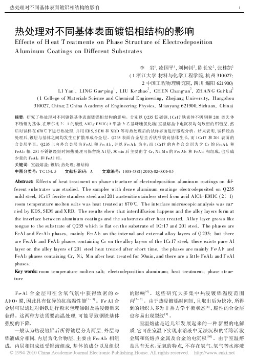
热处理对不同基体表面镀铝相结构的影响
1. 1
镀层制备
Fig. 1
S EM m icrograph of surf ace morph ol ogy
分别采 用 Q 235 低 碳钢 , 1Cr17 铁 素体 不锈 钢, 201 奥氏体不锈钢作为基体试样 ( 阴极 ) , 试样的尺寸 为 30m m ! 10mm ! 1m m 。电沉积前, 基体试样经砂纸 打磨、 酸洗、 丙酮浸泡等处理, 洗净后烘干。阳极材料 选用纯度为 99. 99% 的高纯铝丝, 并经磷酸洗、 水洗、 甲醇洗、 丙酮洗、 干燥等预处理过程。 在氮 气保 护 的真 空 手套 箱 内将 分 析纯 的 无水 AlCl3 与 EM IC 配制成摩尔比 AlCl3 EMIC= 2 1的 室温熔盐体系, 并用铝丝精制 7 天以上 , 备用。 电沉积过程在氮气气氛下的真空手套箱内进行。 接通直流稳压电源, 调节阴极电流密度为 2A/ dm 2 , 沉 积时间 2500s, 得 到约为 17 m 的铝 镀层。沉 积过程 中, 熔盐均经 78 1 型磁力搅拌器磁力搅拌, 以保证熔 盐成分的均匀性。 1. 2 热处理 将电沉积了均匀铝镀层的试样在空气气氛下用电 阻炉 ( Nabert herm ) 进行热处理, 温度 670 , 时间 5~ 60m in, 经热处理后的 试样随炉冷却。对 热处理后的 样品进行相分析及界面观察。 1. 3 检测方法 用金相显微镜( L eica) 对镀层界面进行观察 , 用扫 描电子显微镜 ( F EI) 观察铝镀层的 表面形貌及界面, 用电子能谱 ( EDAX. Phoneix ) 分析镀 铝层的成分, 用 X 射线衍射仪 ( DM AX RA) 分析热处理后铝镀层的相 组成。 2 结果与分析 2. 1 热处理对低碳钢表面铝镀层相组成的影响 三种基体上镀层表面形貌 相近, 典型 的 SEM 照 片如图 1 所示, 镀层均匀致密 , Al 颗粒大小 10 m 左 右, 晶体特征明显。 镀铝 Q235 低碳钢 在 670 下保温 5m in, 外表即 呈灰黑色。10min 热处理后界面的形貌如图 2 所示,
热处理温度对Al复合低碳MgO-C材料组成和结构的影响

热处理温度对Al复合低碳MgO-C材料组成和结构的影响任桢;马成良;钟香崇【期刊名称】《耐火材料》【年(卷),期】2015(49)2【摘要】为了更清楚地观察镁碳材料中Al在200~1 400℃埋炭热处理过程中的变化,以62%(w)的电熔镁砂颗粒(≤5 mm)、32%(w)的电熔镁砂粉(≤0.088 mm)、2%(w)的鳞片石墨和4%(w)的Al粉制备了Al复合低碳MgO-C材料,并采用XRD 和SEM研究了试样分别于200、400、600、800、900、1 000、1 100、1 200、1 300、1 400℃保温3h热处理后的物相组成和显微结构.结果表明:1)200~800℃,材料的物相组成无变化,结合方式为碳结合.2)800 ~1 200℃,粒状Al4C3在900℃开始生成,1 200℃时与N2反应转化为粒状AlN.AlN在1 000℃开始生成,到1 200℃发育长大为针状晶体,材料的结合方式开始转变为非氧化物结合.3)1 200~1 400℃,AlN晶体发育长大,形成交叉连锁的网络,填充在方镁石骨架结构中,致使非氧化物结合更牢固.【总页数】5页(P81-85)【作者】任桢;马成良;钟香崇【作者单位】郑州大学高温材料研究所河南郑州450052;郑州大学高温材料研究所河南郑州450052;郑州大学高温材料研究所河南郑州450052【正文语种】中文【中图分类】TQ175【相关文献】1.金属复合添加剂对低碳MgO-C砖抗氧化性能的影响 [J], 彭肖仟;张巧莲;王志强2.SiC含量对ZrB2-SiC/MgO-C低碳复合耐火材料性能的影响 [J], 王军凯;程峰;韩磊;李赛赛;葛胜涛;宋健波;张海军3.氧化镁含量对MgAl2O4/W复合材料组成和结构的影响 [J], 韩兵强;李楠4.埋炭热处理温度对低碳MgO-C材料相组成、显微结构与力学性能的影响 [J], 伊竟广;朱伯铨;李享成5.热处理温度对Al2 O3 -SiC-Al复合材料性能和结构的影响 [J], 阮国智;李楠;张智慧因版权原因,仅展示原文概要,查看原文内容请购买。
焊后热处理对铝-钢固态连接界面金属间化合物生长的影响

焊后热处理对铝-钢固态连接界面金属间化合物生长的影响焊后热处理对铝/钢固态连接界面金属间化合物生长的影响摘要:随着现代工业的发展,铝/钢固态连接在汽车、电子、建筑等领域得到了广泛应用。
本文通过研究焊后热处理对铝/钢固态连接界面金属间化合物生长的影响,探讨了不同热处理工艺对界面反应的影响机理和界面组织演变规律。
实验结果表明,焊后热处理对铝/钢固态连接界面金属间化合物生成速率、晶粒尺寸和界面形貌有着显著影响。
关键词:焊后热处理、铝/钢固态连接、金属间化合物、界面组织演变1. 引言铝/钢固态连接广泛应用于汽车、电子、建筑等领域,焊后热处理对界面组织演变具有重要意义。
在焊接过程中,铝和钢之间的界面发生化学反应,生成金属间化合物,将两种金属牢固连接起来。
然而,焊接过程中会产生应力,导致界面组织变化,影响焊后性能。
2. 实验方法2.1 实验材料本实验选择常见的6061铝合金和普通碳钢作为材料。
2.2 实验步骤1) 进行铝/钢固态连接焊接2) 进行不同热处理工艺,如固溶处理、时效处理等3) 制备金属log样品并对其进行显微组织分析4) 测量金属间化合物生成速率、晶粒尺寸和界面形貌3. 实验结果与分析3.1 金属间化合物生成速率实验结果显示,焊后热处理能够显著影响金属间化合物的生成速率。
固溶处理能够加速金属间化合物生成的进程,而时效处理能够使金属间化合物的生成速率降低。
这是由于固溶处理能够使界面处的金属原子亚稳状态,促使金属间化合物的快速形成,而时效处理能够使界面处的金属原子逐渐恢复稳定状态,减缓金属间化合物的生成速率。
3.2 金属间化合物晶粒尺寸热处理工艺对金属间化合物的晶粒尺寸也有明显影响。
固溶处理能够使金属间化合物的晶粒尺寸变大,而时效处理能够使金属间化合物晶粒尺寸变小。
固溶处理后,金属间化合物中的溶质原子得到更多的扩散,晶粒尺寸变大;而时效处理中,溶质原子逐渐从金属间化合物中排出,晶粒尺寸因此减小。
3.3 界面形貌焊后热处理还能够影响铝/钢固态连接界面的形貌。
热处理工艺对铝合金组织性能的影响

热处理工艺对铝合金组织性能的影响摘要:随着社会经济的不断发展,对于铝合金材料的应用需求也越来越多。
铝合金产业的发展越来越快,为满足市场不断扩大的需求,铝合金的各种热处理工艺技术也在不断发展进步。
随着我国经济发展水平的不断提高,工业生产技术在不断完善与发展,其中,铝合金是工程应用中最多的,与其他金属相比,其应用过程中的优势较多,在航空、汽车、建筑等领域中应用广泛。
关键词:热处理;铝合金;性能;分析1导言铝合金具有密度小,比刚度、比强度高,导热导电性能良好、塑性好、膨胀系数小、无低温脆性以及较好的耐腐蚀性等优点。
这些优良的性能,是铝合金能够在我国很多领域得到广泛应用的原因。
但是铝合金本身存在的硬度低,耐磨性较差,摩擦系数大等劣势,限制了其在工业以及其它行业上的进一步发展。
近年来,经济建设的快速发展,带动了航空航天、医疗设备、汽车等领域的前进步伐,而铝合金作为社会发展中较为重要的应用材料,对其综合性能的要求也越来越高。
2铝合金热处理的特点为了提高铝合金的力学性能,使其导电性、导热性以及抗腐蚀性增强,一般通常采用热处理的方法来解决。
所谓的热处理是指为了提高沉淀硬化锻压和铸造合金的强度与硬度的一种加热或冷却处理。
相对于钢而言,铝合金具有独特的优势,在高温淬火后,可塑性随之升高,与此同时,铝合金的强度和硬度也会随之升高,然而钢铁在经过热处理后虽然刚度得到一定的提高,但是其可塑性降低了。
3铝合金的特点3.1应用广泛铝合金的应用是非常广泛,经过热处理之后,其材料可以满足很多行业的材料需要,比如建筑业、工业、制造业等。
而且铝合金有很多的类别,比如变形铝合金、铸造铝合金、高塑性铝合金、高强度铝合金等,按照不同的划分标准有着不同的铝合金类别,这也是其能够应用广泛的重要原因。
3.2可塑性高铝合金可塑性是非常高的,这也是其能够应用在各种行业,作为不同行业的原材料的重要原因。
其高可塑性可以根据相关方的实际需要,经过一定的热处理工艺,达到实际需要的材料性能。
热处理对离心铸造自生梯度功能复合材料Al-2OSi-5Mg合金的组织性能影响
K ywo d e r s: h a e t e t h r n s ; a e it n e c n ru a a t g; / 2 e t r a m n ; a d e s we rr ss a c ; e ti g l s i Si t f c n Mg Si
功 能梯度材料 (u ci a y rd d t i ,简称 F n t n l ae e a o lG Ma r l
wa t de Th e ut h w h tte h r n s f h n rly r f h u e c r r a h te hg e t ssu id. e r s l s o t a h a d e so e i e e e t b a ห้องสมุดไป่ตู้ c h ih s s t n a o t v le o au f HRB9 f rs lt n h a r a m e ta 1 ℃ f r6 h n h n e a e ft e t b 0 a e ou i e tte t n t5 t o 0 o .a d t e in rly ro h u e
b n r u a s ig y Ce ti g l f Ca t n
L N Xu — o g. I a g m ig I e d n L U Ch n - n
( ol eo t r l c n ea dE gn e i , o g igU i ri , o g i 0 0 0 Chn ) C l g f e Maei i c n n i r g Ch n qn nv st Ch n qn 4 0 3 , ia aS e e n e y g
F b.2 0 e 01
VoI59 N0. . 2
热 处 理对 离 心 铸 造 自生梯 度 功 能 复 合 材 料A一 0 i5 合 金 的组 织 性 能 影 响 I2 S一 Mg
热处理对金属晶粒生长的影响实现材料结构的精细调控
热处理对金属晶粒生长的影响实现材料结构的精细调控热处理在金属材料加工与制备中起着重要的作用。
它通过控制金属晶粒的尺寸与分布,实现对材料结构的精细调控。
本文将探讨热处理对金属晶粒生长的影响以及其在材料工程中的应用。
一、热处理对金属晶粒生长的影响金属晶体的生长是指晶粒的尺寸和分布在加热或冷却过程中的变化。
热处理是通过控制金属晶粒生长的方式之一。
以下是热处理对金属晶粒生长的主要影响:1. 温度:温度是影响金属晶粒生长速率的关键参数。
高温有利于金属晶粒的扩散和生长,因此在热处理过程中,适当的温度可以促进晶粒的细化。
2. 时间:热处理时间也是影响晶粒生长的重要因素。
较长的热处理时间有助于晶粒的长大,而较短的时间则有利于晶粒的细化。
因此,在实际热处理过程中,需要根据材料的要求确定适当的处理时间。
3. 冷却速率:不同的冷却速率会导致晶粒尺寸和分布的差异。
较快的冷却速率通常会导致晶粒尺寸的减小和分布的均匀化,而较慢的冷却速率则有助于晶粒的长大。
4. 杂质元素:杂质元素的存在也会对金属晶粒生长产生影响。
某些元素可以在晶界上形成弥散势阻,阻碍晶粒的长大,从而细化晶粒。
二、热处理在材料工程中的应用热处理作为一种有效的材料结构调控方法,广泛应用于材料工程领域。
以下是热处理在材料工程中的几个主要应用:1. 细化晶粒:通过适当的热处理方法,可以使金属材料的晶粒尺寸减小到纳米级别。
细小的晶粒具有高强度、高硬度和优异的塑性,因此可以大幅度提高材料的性能。
2. 改善材料的韧性:对于一些易脆断的金属材料,通过热处理可以改善其韧性。
热处理过程中的晶粒再结晶和析出相形成可以增加材料的塑性,从而提高抗拉强度和韧性。
3. 消除残余应力:金属材料在加工过程中会产生残余应力,对材料性能和结构稳定性造成不利影响。
通过适当的热处理方法,可以消除或减小残余应力,提高材料的综合性能。
4. 改善耐腐蚀性:热处理可以改变金属材料的晶粒形貌和化学成分分布,从而提高其耐腐蚀性。
Al双金属层状复合带的轧制及热处理工艺研究的开题报告

Ni/Al双金属层状复合带的轧制及热处理工艺研究的开题报告题目: Ni/Al双金属层状复合带的轧制及热处理工艺研究一、研究背景及意义Ni/Al双金属层状复合带是一种由两种不同金属材料组成的复合材料。
根据其性能特点,Ni/Al双金属层状复合带具有低密度、高强度、高韧性、良好的导热性和尺寸稳定性等特点,在航空航天、汽车工业和电子器件中有广泛的应用。
因此,对其轧制和热处理工艺研究具有重要意义。
二、研究内容1. Ni/Al双金属层状复合带的制备方法研究。
包括原材料选择、合金液淬凝法制备、合金材料织构调控等方面。
2. Ni/Al双金属层状复合带的轧制工艺研究。
包括轧制工艺参数确定、轧制过程中的质量控制和改善等方面。
3. Ni/Al双金属层状复合带的热处理工艺研究。
包括退火、固溶和时效等工艺的优化和改进。
4. 对制备的Ni/Al双金属层状复合带进行表征分析。
包括金相分析、机械性能测试、热膨胀系数测定等方面。
三、研究方法1. 采用真空感应熔炼技术制备合金材料。
2. 采用机械合金化方法制备原始合金粉末。
3. 采用热轧工艺制备Ni/Al双金属层状复合带,并进行相应的质量控制。
4. 对制备的复合带进行退火、固溶和时效处理,并对不同工艺条件下的材料性能进行测试和分析。
四、拟解决的问题1. Ni/Al双金属层状复合带的表面氧化问题。
2. Ni/Al双金属层状复合带的轧制过程中产生的拉伸和剪切损伤问题。
3. Ni/Al双金属层状复合带的热处理过程中组织的演变规律和转变温度的确定问题。
五、工作计划1. 前期阅读相关文献,理解Ni/Al双金属层状复合带的制备、轧制和热处理工艺以及表征分析方法。
2. 开展合金材料的制备工作,并对合金液进行淬凝实验,制备Ni/Al 双金属层状复合带。
3. 对不同轧制工艺条件下的复合带进行质量控制,并对轧制带进行性能测试和表征分析。
4. 对制备的复合带进行热处理工艺优化,包括退火、固溶和时效等工艺的优化和改进。
热处理对耐磨复合材料力学性能的影响
第三章电冶样品的热处理性能表征.............................................................. 21 3.1 密度的影响........................................................................................ 21 3.2 微观结构分析.................................................................................... 22
3.2.1 .淬回火后的组织形态................................................................................ 22 3.2.2 XRD 分析....................................................................................................24 3.2.3 SEM 分析....................................................................................................27
1.2.1 复合材料的概念.......................................................................................... 1 1.2.2 复合材料的分类........................................................................................ 2
热处理对GNP-Al复合材料显微组织和性能的影响
热处理对GNP-Al复合材料显微组织和性能的影响
简正豪;邹金红;陈佳;赵英;曾敏
【期刊名称】《轻金属》
【年(卷),期】2024()6
【摘要】本文以石墨烯为增强相,采用高能超声辅助铸造法及后续热处理制备了铝基复合材料,并研究石墨烯和热处理对复合材料显微组织、力学性能和耐磨性能的影响。
结果表明,石墨烯促进了复合材料晶粒细化,且热处理后Si相进一步细化及圆整。
经热处理后复合材料的屈服强度和抗拉强度(245和319MPa)比基体(119和202MPa)分别提高了105.9%、57.9%。
磨损试验结果表明,添加石墨烯和T6热处理后复合材料的磨损率最低,磨损机制由剥层磨损转变为磨粒磨损。
【总页数】6页(P39-44)
【作者】简正豪;邹金红;陈佳;赵英;曾敏
【作者单位】南昌工学院机械与车辆工程学院;南昌航空大学航空制造工程学院【正文语种】中文
【中图分类】TF821;TB333
【相关文献】
1.热处理温度对(TiB+La2O3)/Ti复合材料的显微组织和力学性能的影响
2.热处理对Ni/Ti_(2)AlC复合材料显微组织和摩擦学性能的影响
3.免热处理
(TiB_(2)+ZrB_(2))/Al-Mg-Mn基复合材料的显微组织与力学性能4.激光选区熔化ZrO_(2)/AlSi10Mg复合材料热处理显微组织与力学性能
因版权原因,仅展示原文概要,查看原文内容请购买。
Al-Fe金属间化合物对复合板界面结合的影响

Trans. Nonferrous Met. Soc. China 24(2014) 279−284Effects of Fe −Al intermetallic compounds oninterfacial bonding of clad materialsQian WANG, Xue-song LENG, Tian-hao YANG, Jiu-chun YANState Key Laboratory of Advanced Welding and Joining, Harbin Institute of Technology, Harbin 150001, ChinaReceived 29 October 2012; accepted 13 March 2013Abstract: The growth of intermetallic compounds at the interface between solid Al and Fe and the effects of intermetallic compound layers on the interfacial bonding of clad materials were investigated. The results showed that the interface between the solid Fe and Al formed by heat-treatment consisted of Fe 2Al 5 and FeAl 3 intermetallic compound layers, which deteriorated the interfacial bonding strength. Fractures occurred in the intermetallic compound layer during the shear testing. The location of the fracture depended on the defects of microcracks or voids in the intermetallic compound layers. The microcracks in the intermetallic compound layer were caused by the mismatch of thermal expansion coefficients of materials during cooling, and the voids were consistent with the Kirkendall effect. The work will lay an important foundation for welding and joining of aluminum and steel, especially for fabrication of Al −Fe clad materials.Key words: Al −Fe clad materials; interfacial bonding; Fe −Al intermetallic compounds; interface structure; mechanical properties1 IntroductionAluminum can effectively improve the properties ofFe with excellent corrosion resistance, reduced mass anddurability. To achieve the combined properties of Al andFe, it is necessary to join these metals. Some differentmethods are used to produce Al/Fe clad materials [1−3].The methods of hot-dipped-aluminum and roll bondingare important production method commonly used tomanufacture Al −Fe cladding materials [4−7]. However,intermetallic compound (IMC) layers composed of FeAl 3, Fe 2Al 5 and others were observed at the interface of Al coating and the steel substrate in theprocess [1−7].The microstructure and phase evolution of the interface of hot-dipped-aluminized mild steel (at 700 °Cfor 180 s) during high-temperature treatment (at 750 °Cfor 5 min to 480 h) have been studied [5]. Fe 2Al 5 andFeAl 3 are observed at the interface of materials. Duringhigh-temperature treatment, FeAl 2 is formed at the interface of Fe 2Al 5−steel substrate in the hot-dipped-aluminized mild steel. Increasing the diffusion treatmenttime, Fe 2Al 5 and FeAl 3 are gradually replaced by FeAl 2and FeAl. Finally, the intermetallic compound layers arecomposed of FeAl 2 and FeAl. The growth of the IMC layers has been found to be controlled by diffusion, and the solutions of diffusion equations have been presented [4]. The liquid −solid roll bonding (750 and 850 °C) methods of joining Al −Sn −Pb alloy and steel have been studied previously [6]. Al −clad Fe sheet is produced by solid −solid (450 and 600 °C) rolling process [7]. In these researches, the Fe −Al intermetallic compound layers were observed at the interface. The intermetallic compound layers are important to obtain materials with excellent performance. Thus, it is essential to understand the effect of different types ofintermetallic compounds at the interface. In this study, solid Al and Fe were heat-treated, and the microstructure of intermetallic compounds was studied. The reactionbetween solid Al and solid Fe as well as influence of the Al −Fe intermetallic compound layers on interfacial bonding was discussed. This work provided guidelines for the prediction and control of interface intermetallic compounds during the welding and joining processes,including producing Al −clad Fe material by roll-bonding under solid-phase conditions, and it also provided a reference for the influence on the interfacial bonding of clad materials.Foundation item: Project (2011DFR50630) sponsored by the International S&T Cooperation of China Corresponding author:Jiu-chunYAN;Tel:+86-451-86416607;E-mail:*************.cn DOI: 10.1016/S1003-6326(14)63058-2Qian WANG, et al/Trans. Nonferrous Met. Soc. China 24(2014) 279−284 2802 ExperimentalThe 1.5 mm-thick plate of pure Fe coated with a 0.07 mm-thick film of Al was used as core material in this study. The plates were cut to dimensions of 45 mm× 10 mm×1.5 mm. Figure 1 shows the interfacial microstructure of the Fe coated with Al produced by roll-bonding. The interface was clean and not composed of Al−Fe intermetallic compounds.Fig. 1 Backscattered electron image of Al−Fe clad materialsIn this work, the solid Fe and solid Al were heated to 620 °C or (630±2) °C and held for 120 min in air. Thereafter, they were cooled to room temperature.The mechanical properties of the interfacial bonding were measured using a special method for shear strength tests. A 5A06 aluminum plate with dimensions of 45 mm×10 mm× 4 mm was joined to a Fe−Al clad materials plate, as shown in Fig. 2. The bonding strength between the 5A06 Al and the pure Al coating layer is stronger than that between the Fe substrate and the Al coating layer. Tensile shear strength tests were carried out at room temperature at a cross-head speed of 1 mm/min using a tensile testing machine (Instron−5569).Fig. 2 Schematic diagram of tensile shear samplesThe specimens were cross sectioned for metallographic analyses using an electrical-discharge cutting machine. The cross sections of the metallographic specimens were polished with a diamond polishing agent. The interfacial structure and elemental distribution in the joint were analyzed by SEM equipped with an EDX spectroscopy analysis system (HITACHI S−4700). The phase structure on the surface of fracture of the joints was determined by XRD (D/max-rB). 3 Results and discussion3.1 Interface structure of Al−Fe clad materials heatedat 630 °CFigure 3 shows the microstructure and elemental distributions of the interface of Al−Fe clad materials heated at 630 °C for 120 min. There were defects (Fig. 3(a)), such as microcracks and voids, in the intermetallic compound layers. Most of the microcracks ran along almost the length of the interface direction. Figure 3(b) shows the lap joints consisted of four parts: an un-reacted Al coating, a darker gray phase, a lighter phase layer and a Fe substrate. There were continuous lines in Fig. 3(b), indicating that intermetallic compound layers existed at the interface. The darker gray phase was Al-rich, and the lighter phase was Fe-rich. The Al-rich and Fe-rich intermetallic compound layers were termed IMC1 and IMC2, respectively. A small amount of IMC1 existed close to the Al coating. Majority of the intermetallic compounds was IMC2.Figure 4 shows the cross section of the fracture of Al−Fe clad materials heated at 630 °C for 120 min after the tensile test. The fracture location was in the IMC2,Fig. 3 Microstructure and elemental distributions of Al−Fe clad materials heat treated at 630 °C for 120 min: (a) Backscattered electron image; (b) Elemental distribution along white scanning line in (a)Qian WANG, et al/Trans. Nonferrous Met. Soc. China 24(2014) 279−284 281Fig. 4 SEM image showing fracture location of Al−Fe clad materials heat treated at 630 °C for 120 min after tensile testand the fracture was along almost the length of the interface direction with IMC2.Figure 5 (a) shows the secondary electron image of the fracture surface of Al−Fe clad materials heat treated at 630 °C for 120 min after the tensile test. In Fig. 5(a), the bright and dark zones occurred because the fracture occurred in different compound layers. The fracture location of the black zones was deeper from the Fe side and closer to the Fe substrate than the light zones.Fig. 5 Secondary electron image (a) and XRD pattern (b) of tensile fracture surface morphology of Fig. 4To further determine the type of intermetallic compound layers formed at the interface of Al−Fe clad materials heated at 630 °C for 120 min, the XRD pattern from the fractured surfaces of the Fe sides was analyzed (Fig. 5(b)). Fe2Al5, FeAl3, Fe, Al and Al2O3 were detected in the XRD pattern and majority of the intermetallic compounds was Fe2Al5 phase. Therefore, the interface of Al−Fe clad materials heated at 630 °C for 120 min mainly consisted of Fe2Al5 and FeAl3 layer. IMC1 was FeAl3 and IMC2 was Fe2Al5. The fractures mainly occurred at the Fe2Al5 intermetallic compound layer during the tensile−shear test.3.2Interface structure of Al−Fe clad materials heatedat 620 °CFigure 6 shows the microstructure and elemental distribution at the interface of Al−Fe clad materials heated at 620 °C after 120 min. The continuous lines were observed in Fig. 6(b), indicating that intermetallic compound layers were generated. Figure 6(a) shows that the lap joints consisted of four parts: an un-reacted AlFig. 6 Microstructure and elemental distribution of Al−Fe clad materials heat treated at 620 °C for 120 min: (a) Backscattered electron image; (b) Elemental distribution along white scanning line in (a)Qian WANG, et al/Trans. Nonferrous Met. Soc. China 24(2014) 279−284 282coat, a darker gray phase, a lighter phase layer and a basematerial of Fe. The darker gray phase was Al-rich, and the lighter phase was Fe-rich, which were termed IMC3 and IMC4, respectively. The IMC3 layer was thicker than the IMC4 layer. There were no obvious microcracks or voids in IMC4. However, there were some defects such as voids and microcracks in IMC3.Figure 7 shows the cross section of the fracture of Al/Fe clad materials heated at 620 °C for 120 min after the tensile test. The fracture existed along almost the length of the interface direction, and occurred at IMC3. SEM micrograph of the fracture surface is shown in Fig. 8(a). The bright and dark zones were observed because the fracture occurred in different compound layers. The fracture location of the light zones was much shallower from the Fe substrate and closer to the Al coat layer than the dark zones.Fig. 7 SEM image showing fracture location of Al−Fe clad materials heat treated at 620 °C for 120 min after tensile testThe intermetallic compound layers formed at the interface of Al−Fe clad materials heat treated at 620 °C for 120 min were analyzed by XRD from the fractured surface of the Fe sides. The results from the fractures are shown in Fig. 8(b). The intermetallic compound of FeAl3 with Fe2Al5, Al and Al2O3 elements was found to be present. IMC3 was FeAl3 and IMC4 was Fe2Al5. The light zones were FeAl3 phase. The overwhelming majority of fractures occurred in the FeAl3 intermetallic compound layer during the tensile test and only a few fractures occurred in the Fe2Al5 intermetallic compound layer.3.3 Reaction of solid Al and solid FeFrom the above analysis and Fe−Al binary diagram, it was concluded that the interface of solid Al coating and solid Fe substrate involved the formation of Fe−Al intermetallic compounds. The layer composition gradually approached the composition of the Al-rich intermetallic compounds from the Fe substrate to the Al coating.Fig. 8 Secondary electron image (a) and XRD patterns (b) of tensile fracture surface morphology in Fig. 7During the reaction between solid Al and solid Fe, the formation of the Fe2Al5 and FeAl3 phase was detected and other Fe−Al phases were not found, which was consistent with the reaction between liquid Al and solid Fe as observed by other authors [4,5,8]. However, the morphology of intermetallic compounds at the solid–solid interface was different from that at the solid–liquid interface.The Fe2Al5 phase was slightly tongue-like and regular with peaks oriented towards Fe. However, the FeAl3 layer was slightly thicker than the Fe2Al5 layer in this work, and the morphology of the FeAl3 phase was not thin needles or platelets uniformly dispersed in the solidification aluminum matrix which was reported by other authors [4,5,8]. The thickness of the two intermediate phases was 20−50 μm. However, the thickness of the two intermediate phases was more than 100 μm when the solid–solid interface reacted only a few minutes [4,5,8]. The inter-diffusion controlled their growth, and the growth rate of the two intermediate at solid–solid interface was slower than that at solid–liquid interface.3.4 Effect of Fe−Al intermetallic compoundsFigure 9 shows that the shear strength to fractureQian WANG, et al/Trans. Nonferrous Met. Soc. China 24(2014) 279−284 283 occurred at different locations after the tensile−shear test.The shear strength of the original Al−Fe clad materials was about 70 MPa. However, the shear strength was only about 20 MPa when the fracture occurred at the intermetallic compound layers. Both Fe2Al5 and FeAl3 caused deterioration of the Al−Fe clad materials bonding.Fig. 9 Shear strength to fractures occurring at different locationsIn this study, the defects at the interface of Fe−Al reaction layers were observed [3,9,10]. However, the fractures mainly occurred at the intermetallic compound layer of Fe2Al5 or FeAl3, which was different from other reports [11−15]. The location of the fracture depended on the defects in Fe2Al5 and FeAl3 layers. The intermetallic compounds led to the fracture of the weakest part of the interface. Therefore, the intermetallic compound layer significantly deteriorated the mechanical properties of the interface.The thermal expansion coefficients for Fe (12.2× 10⁻⁶ K−1), Al (23.5×10⁻⁶K−1) and Al−Fe intermetallic compounds (18.94×10⁻⁶ K−1 for Fe2Al5, 19.68×10⁻⁶ K−1 for FeAl3) [16,17] were different from each other. The intermetallic compound layers usually formed at a higher temperature. During cooling, the different thermal expansion coefficients of the Fe substrate, Al coating and intermetallic compounds caused residual stress along the interface direction. This further caused internal microcracks which were found in the intermetallic compound layer. Microcracks were the main factor of the fracture.According to results of CHENG and WANG [5], the formation of internal voids resulted from the Kirkendall effect. The different diffusion rates of Fe and Al caused a net flux of vacancies to the interface where voids condensed out. The Kirkendall effect was a rational mechanism for voids observed at the interface. The voids resulted in stress concentration which accelerated the expansion of the crack. 4 Conclusions1) Intermetallic compounds of Fe2Al5 and FeAl3 were detected at the interface of Al−Fe clad materials with heat-treatment. The interface between the solid Fe and solid Al with heat-treatment consisted of Fe2Al5 intermetallic compound layer and FeAl3 intermetallic compound layer. The morphology of intermetallic compounds at the solid−solid interface was different from that at the solid–liquid interface.2) The intermetallic compound layers significantly deteriorated the mechanical properties of Al−Fe clad materials. Shear strength decreased from 70 to 20 MPa. The fractures mainly occurred at the Fe2Al5 or FeAl3 intermetallic compound layer after tensile test.3) The defects in the Fe2Al5 and FeAl3 layers are the dominant element of controlling the location of the fracture. The formation of internal microcracks in the intermetallic compound layers was caused by the thermal expansion coefficient mismatch between the materials, and the formation of internal voids was consistent with the Kirkendall effect.References[1]ZHU Xiao-lin, YAO Zheng-jun, GU Xue-dong, CONG Wei,ZHANG Ping-ze. Microstructure and corrosion resistance of Fe−Alintermetallic coating on 45 steel synthesized by double glow plasmasurface alloying technology [J]. Transactions of Nonferrous MetalsSociety of China, 2009, 19(1): 143−148.[2]ZHAN Zhao-lin, HE Ye-dong, WANG De-ren, GAO Wei.Preparation of aluminide coatings at relatively low temperatures [J].Transactions of Nonferrous Metals Society of China, 2006, 16(3):647−653.[3]LEE Jung-Han, KIM Jong-Do, OH Jin-Seok, PARK Seo-Jeong.Effect of Al coating conditions on laser weldability of Al coated steelsheet [J]. Transactions of Nonferrous Metals Society of China, 2009,19(4): 946−951.[4]BOUCHE K, BARBIER F, COULET A. Intermetallic compoundlayer growth between solid iron and molten aluminium [J]. MaterialsScience and Engineering A, 1998, 249(1−2): 167−175.[5]CHENG W, WANG C. Study of microstructure and phase evolutionof hot-dipped aluminide mild steel during high-temperature diffusionusing electron back scatter diffraction [J]. Applied Surface Science,2011, 257(10): 4663−4668.[6]XU G, LI B, CUI J. Interfacial microstructure of Al−Sn−Pballoy-steel during liquid-solid bonding rolling [J]. Journal of Iron andSteel Research International, 2006, 13(4): 40−43.[7]DANESH MANESH H, KARIMI TAHERI A. Bond strength andformability of an aluminum-clad steel sheet [J]. Journal of Alloys andCompounds, 2003, 361(1−2): 138−143.[8]AGUDO L, EYIDI D, SCHMARANZER C H, ARENHOLZ E,JANK N, BRUCKNER J. Intermetallic Fe x Al y-phases in a steel/Al-alloy fusion weld [J]. Journal of Material Science, 2007,42(12): 4205−4214.Qian WANG, et al/Trans. Nonferrous Met. Soc. China 24(2014) 279−284 284[9]CHANG Y, TSAUR C C, ROCK J C. Microstructure studies of analuminide coating on 9Cr−1Mo steel during high temperature oxidation [J]. Surface and Coatings Technology, 2006, 200(22−23):6588−6593.[10]BOUAYAD A, GEROMETTA CH, BELKEBIR A, AMBARI A.Kinetic interactions between solid iron and molten aluminium [J].Materials Science and Engineering A, 2003, 363(1−2): 53−61. [11]BORRISUTTHEKUL R, YACHI T, MIYASHITA Y, MUTOH Y.Suppression of intermetallic reaction layer formation by controllingheat flow in dissimilar joining of steel and aluminum alloy [J].Materials Science and Engineering A, 2007, 467(1−2): 108−113. [12]PEYER P, SIERRA G, DESCHAUX-BEAUME F, STUART D,FRAS G. Generation of aluminium-steel joints with laser-induced reactive wetting [J]. Materials Science and Engineering A, 2007, 444(1−2): 327−338. [13]SIERRA G, PEYRE P, DESCHAUS-BEAUME F, STUART D,FRAS G. Steel to aluminium key-hole laser welding [J]. Materials Science and Engineering A, 2007, 447(1−2): 197−208.[14]SIERRA G, PEYRE P, DESCHAUX-BEAUME F, STUART D,FRAS G. Galvanised steel to aluminium joining by laser and GTAW processes [J]. Materials Characterization, 2008, 59(12): 1705−1715.[15]CHEN Y C, KOMAZAKI T, KIM Y G, TSUMURA T, NAKATA K.Interface microstructure study of friction stir lap joint of AC4C cast aluminum alloy and zinc-coated steel [J]. Materials Chemistry and Physics, 2008, 111(2−3): 375−380.[16]MASAHASHI N, WATANABE S, NOMURA N, SEMBOSHI S,HANADA S. Laminates based on an iron aluminide intermetallic alloy and a CrMo steel [J]. Intermetallics, 2005, 13(7): 717−726. [17]LIU Jin-bang. Steel hot dipped aluminum [M]. Beijing: MetallurgyIndustry Press, 1995: 14−15. (in Chinese)Al−Fe金属间化合物对复合板界面结合的影响王 谦,冷雪松,杨天豪,闫久春哈尔滨工业大学先进焊接与连接国家重点实验室,哈尔滨 150001摘 要:对固态铝和固态铁界面金属间化合物的生长及金属间化合物对界面结合的影响进行了研究。
时效处理及铝合金中其它元素对合金的影响

时效处理及铝合金中其它元素对合金的影响铝棒均质炉在铸造铝棒的过程中,铝棒内部化学成分和组织有不均匀的现象,同时内部一般都存在着残余应力,为消除铸锭的残余应力,消除铸锭的化学成分和组织的不均匀,进而改善铸锭的压力加工工艺性以及制品的某些最终性能,这就一定要对铸锭进行均匀处理固溶热处理:将合金加热至高温单相区恒温保持,使过剩相充分溶速冷却,以得到过饱和固溶体的热处理工艺(绝大多数进行时效强化的合金,原始组织都是由一种固溶体和某些金属化合物所组成。
固溶体的溶解度随温度的上升而增大。
在时效处理前进行淬火,就是为了在加热时使尽量多的溶质溶入固溶体,随后在快速冷却中溶解度虽然下降,但过剩的溶质来不及从固溶体中分析出来,而形成过饱和固溶体。
为达到这一目的而进行的淬火常称为固溶热处理。
)时效处理可分为自然时效和人工时效两种自然时效是将铸件置于露天场地半年以上,便其缓缓地发生形,从而使残余应力消除或减少,人工时效是将铸件加热到550~650℃进行去应力退火,它比自然时效节省时间,残余应力去除较为彻底.根据合金本性和用途确定采用何种时效方法。
高温下工作的铝合金适宜用人工时效,室温下工作的铝合金有些采用自然时效,有些必须人工时效。
从合金强化相上来分析,含有S相和CuAl2等相的合金,一般采用自然时效,而需要在高温下使用或为了提高合金的屈服强度时,就需要采用人工时效来强化。
比如LY11和LY12,40度以下自然时效可以得到高的强度和耐蚀性,对于150度以上工作的LY12和125-250度工作的LY6铆钉用合金则需要人时效。
含有主要强化相为MgSi,MgZn2的T相的合金,只有采用人工时效强化,才能达到它的最高强度。
对于一般铝合金,自然时效时,屈服强度稍低而耐蚀性较好,采用人时效时,合金屈服强度较高而伸长率和耐蚀性都降低。
对于铝-锌-镁-铜系合金入LC4则相反,当采用人工时效时,合金耐蚀性比自然时效好。
铝中合金元素和杂质对性能的影响1 合金元素影响铜元素铝铜合金富铝部分平衡相图如图所示。
《2024年高压处理和增强相尺寸对Al-Al2O3复合材料组织性能的影响》范文
《高压处理和增强相尺寸对Al-Al2O3复合材料组织性能的影响》篇一高压处理和增强相尺寸对Al-Al2O3复合材料组织性能的影响一、引言随着现代工业技术的快速发展,复合材料因其独特的物理和化学性能,在航空航天、汽车制造、电子信息等领域得到了广泛应用。
Al/Al2O3复合材料作为一种典型的金属基复合材料,因其高强度、高硬度、良好的耐磨性和优异的热稳定性等特点,受到了广泛关注。
本文将探讨高压处理和增强相尺寸对Al/Al2O3复合材料组织性能的影响。
二、Al/Al2O3复合材料的制备Al/Al2O3复合材料的制备通常包括原料选择、混合、成型和烧结等步骤。
其中,增强相Al2O3的添加能够显著提高复合材料的性能。
而增强相的尺寸则直接影响复合材料的组织结构及性能。
三、高压处理技术及其对Al/Al2O3复合材料的影响高压处理技术是一种有效的金属材料强化方法,对Al/Al2O3复合材料的组织性能具有显著影响。
高压处理过程中,金属基体中的原子重新排列,晶粒细化,同时增强相与基体之间的界面结合力得到增强。
这有助于提高复合材料的硬度、强度和耐磨性等性能。
四、增强相尺寸对Al/Al2O3复合材料的影响增强相的尺寸是影响Al/Al2O3复合材料性能的重要因素。
一般来说,较小的增强相尺寸有利于提高复合材料的强度和韧性。
因为小尺寸的增强相能够更有效地阻碍位错运动,提高材料的抗变形能力。
然而,过小的增强相可能导致基体与增强相之间的界面结合力减弱,从而影响复合材料的整体性能。
因此,选择合适的增强相尺寸对于优化Al/Al2O3复合材料的性能至关重要。
五、高压处理与增强相尺寸的协同作用高压处理和增强相尺寸的协同作用对Al/Al2O3复合材料的组织性能具有重要影响。
在高压处理过程中,较小的增强相尺寸有助于晶粒细化,进一步提高材料的硬度、强度和耐磨性。
同时,增强相与基体之间的界面结合力在高压作用下得到进一步增强,从而提高复合材料的综合性能。
- 1、下载文档前请自行甄别文档内容的完整性,平台不提供额外的编辑、内容补充、找答案等附加服务。
- 2、"仅部分预览"的文档,不可在线预览部分如存在完整性等问题,可反馈申请退款(可完整预览的文档不适用该条件!)。
- 3、如文档侵犯您的权益,请联系客服反馈,我们会尽快为您处理(人工客服工作时间:9:00-18:30)。
atr rl n fe o l g,e tb ih d i s l e .T e r s l n i ae h tt e t i k e s o e F / 1 c mp u d e ta sg i c tr lt n h p a s h e u t i d c t d t a h h c n s f t e A o o n s k p in f a e ai s i s h in o i h t e h l i gt n od n e e au e h l t e p e r l n e t r ame t u d e e t l i i t e g w f h w t h o dn mea d h l i gt mp r t r ,w i h r —ol g h a e t n o l f c iey i hb t h o h o e i e i t c v n r t t
总第 1 1 8 期 21 0 1年 8月
南
方
金
属
S m.1 1 u 8 Au 2 1 g 01
S OUTHERN METAL S
文章编号 : 0 9— 7 0 2 1 )4— 0 7— 4 10 9 0 (0 1 0 0 2 0
热处理对 A/ e 1F 双金属 复合材料结合层 中间 相 生 长 规 律 的影 响
W AN Be ,L i i ,W A G i IL — n x NG a — a g Xio g n
( col f t i s dMeaug , h nU iesyo c n eadT c nl ,Wu a 30 1Hue) S ho o e a t lr Wu a nvrt f i c n eh o g Ma r l a n l y i Se o y hn4 0 8 , bi
S U H R L 0 T E N ME A S
1 实验材料与方法
1 1 实验材 料 .
1 2 实验方 案设 计 .
试验采 用 正 交 试 验 设 计 , 轧 前 保 温 温 度 以
、
保 温时 间 和轧 后热 处理保 温 温度 、 温 时 间 保
试 验选用 30 03与 Q 3 B作 为 复 合 原 料 , 样 25 试
-
. ‘ | 1 l
E co a  ̄tn t l e ma
广 ——— 而 —— —’ 。
图 1 透射 电镜下试样 8的组织
图1 为试 样 8在透 射 电镜下放 大 5 0倍 的界 面 0 情况 , 4为各测 点 的成分 分 析 结 果 . 然 , 1上 表 显 图 部分 灰暗组 织是 铝材 , 下部 分浅 灰组 织是钢 材 , 中 而 间参 差不 齐 的长 条纹 为 A/ e化合 物 FA 1F e 1 .
汪 蓓 , 立新 , 李 王小 刚
( 武汉科技 大学 材料与冶金学 院, 湖北 武汉 40 8 ) 30 1 摘 要: 为了探究轧制前后热处理工艺参数对 双金属 复合 材料结 合层 中间化合 物 (nem t l o pu d , i r e lccm o ns 以下 简 t ai
称 I 生长规律 的影 响 , MC) 设计正交实验 , 2 对 5组试样在 不 同轧前 及轧 后热处 理条 件下 中间化合物 的厚 度进行 了 实测 , 以此为基础 , 建立 了 F/ 1 eA 双金属界 面上 中间化 合物厚 度与轧 制前后 保温 温度 、 保温 时间 的相 关关 系模 型, 结果表 明 : 中间化合物 的厚度与轧制前后保 温温度 、 保温 时间均有 密切关 系 , 轧前 热处理 对 I MC的生 成 、 生长有 抑
t a n eoeadae ln nt rwhrl fh t m t l o p ud (MC nA 一ebm t .T et c— r t t bfr n f r o igo ego t e o ei e eai cm o n s I )i 1 iea h ik e me s t rl h us t nr lc F 1 h
尾 政 一 、 藤光 昭 等人 实 验 研 究 了 30 加 03和 Q 3 25分 别 在真空 和空气 中轧制后 热 处理 过程 中 I MC的生 长 规律, 结果表 明 : 同样条件 下 , 真空 中轧 制材 料 的 I MC 厚 度较大 . 一 现 象 说 明 轧后 热 处 理 是 促 使 I J这 MC 形成 的主要 因素 , 而空气 中轧制材料 表 面发生 的氧化
同, 即随 着 温度 的升 高 ,M 的厚 度增 加 ; 温 时 间 IC 保 越 长 , 同一 的保温 温度 下 , 在 I MC厚 度越 大 .
窨
i
毯
碴
图 4 理论上保 温时间相同时 I MC厚 度 与 时 间 的 关 系
量
i
图 2 保温 时间相同时 I MC厚 度 与 温 度 的 关 系
一
对 I C的形成起 抑制作用. M 依据这一结果 , 以推 可 断: 如轧前有意识地使材料表面形成一薄层氧化膜 ,
将对 I C的生长起更 好 的抑制 作 用. 照此 思路 , M 按 同
般来说 , 厚度介于 3— m的 I C不会减弱界面 5 M
层 的结合强度 , 但当其厚度增至 1 m时 , 铝双 O 钢/ 金属复合材料界 面的结合强度将急剧下降 . J 日本
越
3 2 轧 后保 温 时 间对 A/ e化合 物 生长 的影 响 . 1F
各保 温 温度 条 件 下 , 温 时 间对 A/ e结 合 界 保 IF 面化 合 物生 长 的影 响规律 如 图 3所 示 . 然 , 显 随着 保
温时间的增加 , 界面化合物 的厚度越来越大 , 并随保 温时间的延长, 生长速度有加快 的趋势. 但是在保温
h s f h o o n a e s me s r d,a d i e ain h p w t h od n e ea u e n o d n i eo e a d e s o e c mp u d l y rwa a u e t n t r lt s i i t e h l i g t mp r t r s a d h l i g t s o h me b fr n
制作用.
关键词 : 铝复合材料 ;中间化合物 ;结合强度 ;扩散 钢/
中图分类 号 : G16 T 5 文献标识码 : A
Efe t fh a r a m e n h r wt ulso f c so e tte t nto t e g o h r e f t e i e m e alc c m p un n AIFe b m e a s h nt r t l o i o dsi - i t l
I C. M
Ke r s:A1 F i t ;i tr tl c c mp u d;b n te gh;d f s y wo d / e b mea l n emeal o o n i o d sr n t iu i o
钢/ 铝双金属复合材料因同时具有钢的高强度 、
良好 塑性 和 铝 的耐 腐 蚀 、 导 电 、 导 热 等 优 良性 高 高
h= . 2×1 ×E P 71 0t X (一10O 0 R ) ( ) 2 0 / T 1
将本文的实验数据保温时间和保温温度 , 代人
( ) 得 中 间层厚 度与 温度 及 保 温 时 间 的关 系 如 图 1式
4 5所示 . 、
合物的生长随保温温度的变化. 显然 , 在相同的保温 时间条件下, 1F 间化合物厚度生 成规律基本相 A/ e
化 学成 分 、 尺寸 和力学 性能 如表 1和表 2所示 .
为影 响 因子 , 方案如 表 3所 示. 其
表 1 30 、 2 5 0 3 Q 3 B的 化 学 成 分
%
表 2 30 、 2 5 0 3 Q 3 B的 尺 寸及 力学 性 能
保 温 温度取 20— 0 0 4 0℃ , 时间为 3~1 i; rn 轧后 保 1a 温温度 取 45~ 7 C, 间 为 l 2 , 用 的 退 7 55o 时 2~ 8h 所 火炉 型号 为 S 2— . X 2 5—1 . 0
Ab t a t sr c :Or o o a x e me tlt ssb s d o 5 go p fs mp e e e c n u td t n e t a et e e e t f h e t t g n l p r n a e t a e n 2 r u so a l sw r o d ce o iv si t h f cso e h a h e i g f t
图2 为不 同 轧 后 保 温 时 间 条 件 下 , 1F 间 化 A/ e
总第 1 1 8 期
汪
蓓, : 等 热处理对 A/ e双金 属复合材料结合层 中间相生 长规 律的影响 1F
%
表 4 取样点的化学元素成分
中间层厚 度 h和轧 后保 温 时间 t保温 温度 间的关 、
系式 为
远 超过 本文 实验 的测定 值 , 另外 图 2 4及 图 3 5的 、 、
性 态也 有差 别 , 这说 明轧 前 热 处理 亦 是 影 响 I MC生
长 的重 要 因素 . 3 3 实验数 据 的拟 合处 理 .
一
般认为 , C的生成是结合面两边材料相互 I M
扩散 的结果 , 参照( ) , 中间层厚度与轧前保温 1式 设
能, 而在工 业和 民用等 领域 得到 越来越 广 泛 的应 用¨ . J制造 钢/ 双金 属 复合 材料 的关 键就 是 要 求 铝 其结合层之间具有较 高的结合强度 , 而轧制后 的热 处理工艺往往会导致脆性的结合层 中间化合物 ( — i n t m tl o pud , C 生成 , e e l cm on sI ) r ai c M 致使材料失效 . J
2 实验结果
编号 , r ℃ t mn T % n / o i / / th 保温后厚度 m /