HS25JC-2C中文资料
电气常用文字符号及二次接线图的识别
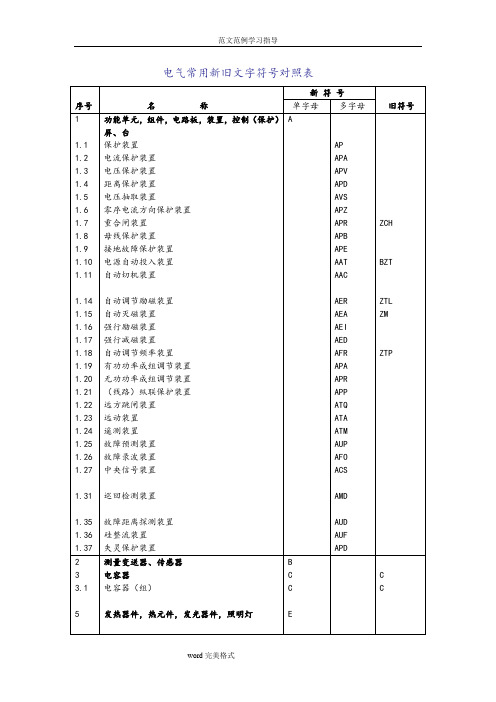
电气常用新旧文字符号对照表附表一二次回路接线图中常见的文字符号序号符号文字解释序号符号文字解释1 DL 继路器及其辅助触点 31 JSJ 加速继电器2 WJ 温度继电器 32 YZJ 电压中间继电器3 G 隔离开关及其辅助触点 33 ZXJ 指挥信号中间继电器4 WSJ 瓦丝继电器 34 WH 有功电度表5 LH 电流互感器 35 XKJ 选控继电器6 ZCH 重合闸继电器 36 VARH 无功电度表7 YH 电压互感器 37 XCJ 选测继电器8 BCJ 保护继电器 38 KK 控制开关9 HQ 合闸线圈 39 FJ 复归继电器10 ZJ 中间继电器 40 HK 转换开关11 HC 合闸接触器 41 ZZJ 重复中间继电器12 HWJ 合闸位置继电器 42 ZK 自动开关13 TQ 跳闸线圈 43 XZJ 信号中间继电器14 TWJ 跳闸位置继电器 44 CK 测量转换开关15 LJ 电流继电器 45 XJJ 信号监察继电器16 HJ 合闸继电器 46 XK 信号转换开关17 YJ 电压继电器 47 TBJ 跳跃闭锁继电器18 TJ 跳闸继电器 48 DK 刀开关19 SJ 时间继电器 49 YJJ 压力监视中间继电器20 TJJ 同步检测继电器 50 MK 灭磁开关21 CJ 差动继电器 51 A 电流表22 XMJ 信号脉冲继电器(冲击继电器) 52 LK 联动开关23 GJ 功率继电器 53 V 电压表24 JJ 监察继电器 54 XWK 限位开关25 XJ 信号继电器 55 W 有功功率表26 SXJ 事故信号中间继电器 56 XD 信号灯27 RJ 热继电器 57 WAR 无功功率表28 YXJ 预告信号中间继电器 58 LD 绿色信号灯29 BSJ 闭锁继电器 59 STK 手动同期转换开关30 HZ 频率表 60 QA 起动按钮续附表一序号符号文字解释序号符号文字解释61 HD 红色信号灯 91 YM 电压互感器二次电压小母线62 RD 熔断器 92 L 电感63 GD 光字牌 93 ZM 转角变压器小母线64 JRD 击穿保险 94 D 二极管65 WS 位置指示灯95 XDC 蓄电池66 RRD 弱电熔断器(热线轴) 96 BG 晶体三极管67 FM 蜂鸣器 97 Z 整流器68 KM 控制回路小母线 98 DS 电磁铁69 DO 电笛 99 R 电阻70 RKM 弱电控制回路电源小母线 100 LP 连接片71 JL 警铃 101 RF 附加电阻72 XM 信号回路电源小母线 102 QP 切换片73 HA 合闸按钮 103 BD 白色信号灯74 RXM 弱电信号回路电源小母线75 TA 跳闸按钮76 NQM 事故音响信号小母线77 FA 复归按钮78 +SM 闪光信号小母线79 ZXA 指挥信号按钮80 (+)HM 合闸电源小母线81 YJA 中央音响信号解除按钮82 FM 辅助小母线83 YA 试验按钮84 YBM 预告信号小母线85 SA 事故按钮86 RM 掉牌未复位“光字牌”87 THM 同期合同小母线88 ZYM 指挥装置音响小母线89 C 电容教学题目:二次接线图的识别教学目的:1、使学员认识到二次回路在发电厂和变电站中的重要性;2、学员能理解、掌握二次图中图形符号所对应的含义;3、让学员掌握绘制二次接线图的方法和原则;4、学员能阅读各种电气二次接线图。
斯普拉克·舍侯CDP2定义功能开关说明书

C D P 2 C o n t a c t o r sA178visit /ecatalog for pricing and the most up to date information/ecatalog - All pricing shown in US dollars - FY20®Series CDP2Definite Purpose ContactorsHigh performance economical contactorsfor commercialapplications up to 90ASprecher + Schuh’s Definite Purpose contactors are ideal for commercial applications including air conditioning, refrigeration, resistive heating and many other installations where a low cost, high performance contactor is needed. These devices offer flexibility and are designed to meet or exceed electrical and mechan-ical requirements as defined by definite purpose contactor standards.Popular sizes for mostapplicationsThe CDP2 series consists of one, two, three and four pole contactors rated to 600V AC. Three pole devices range up to 90A, while the one and two pole models are rated to 40A. Four pole contactors are also available ranging from 25A to 40A.Flexibility and convenience make installation easyCDP2 contactors are compact in size and offer three convenient methods of wire connection: quick connect termi-nals, screws or box lugs. Box lugs are standard on 40A and larger contactors. Other models come standard with combination quick connect terminals and screws that accept hex, slotted or phillips screwdrivers.Standard Features• Universal mounting plate• 25A & 30A have screw power ter-minals that will accept ring-tongue terminals• 40A and larger have box power termi-nals• Dual quick-connect power terminals on all sizes• Dual quick-connect coil terminals on all sizes• Double break power contact design with feed-thru wiring• Class B (130°C) coil insulation • Double E magnet assemblyOptional Features• SPDT auxiliary contacts optional on 3- and 4-pole contactors (max of two)• Optional covers for 1- and 2-pole contactors• Mechanical interlock for 3-pole contactorsOne Pole30A 40ATwo Pole40AThree Pole30A 40A 50A 60A 75A 90AFour Pole30A 40ATwo Pole30AC D P 2 C o n t a c t o r sAA179visit /ecatalog for pricing and the most up to date information/ecatalog - All pricing shown in US dollars - FY20Compare These FeaturesQuick Selection GuideBuilt-in Shock AbsorberReduces contact bounce for longer life.Coil Dust CoverKeeps dust and dirt away from magnet and coil area.Snap-on Auxiliary Contact(optional on 3 and 4 pole contactors) One or two SPDT (shown) available. Also 1NO and 1NC with 600V AC rating.Base AssemblyHigh arc resistant polyester holds stationary terminals, positions actua-tor and magnet/coil assembly.Industry Standard Mounting PlateEasily accessible mounting holes.Coil Terminals#6 - 32 screw and one .250 Quick Connect or Dual .250 Quick Con-nects (will accept two insulated quick connect terminals).Double E Magnet AssemblyProvides optimal performance with reduced power consumptionStationary TerminalOne piece terminal design with integral dual .250 Quick Connects. Meets NEMA standard for spacing without insulated terminals.ActuatorMolded from high arc resistant polyester, holds upper magnet, movable contacts and contact springs position.Movable ContactsHeavy duty silver cadmium oxide composition to resist welding and contact erosion for greater reliabilityCoilClass B (1300 C Insulation System) with wide range of voltages and 50/60 Hz ratings. Includes shading coil that reduces contact chatter.➊ Screw power terminals standard on 30A. Box lug power terminals standard for 40A and larger.➋ Box lugs on 30A available with volume special order only.C D P 2 C o n t a c t o r sA180visit /ecatalog for pricing and the most up to date information Discount Schedule B8/ecatalog - All pricing shown in US dollars - FY20One and Two Pole Definite Purpose Contactors with AC Coil (Open type only) ➍FullLoad AmpsPoles Locked Rotor Amps Resistive Amps ➋Maximum H.P .Catalog NumberStd. Pkg.1Ø240V ➋480V600V120V 240V ➋30 ➊ 1 ➏150********CDP2-A1P30A-✱ ➎5030 ➊21501251004023CDP2-A2P30A-✱ ➎5040 1 ➏2001501205023CDP2-A1P40A-✱ ➌504022001501205023CDP2-A2P40A-✱ ➌50Series CDP2 1-pole contactorSeries CDP2 2-pole contac-tor (with optional cover)➊ 25A contactors only available by special order. Contact your Sprecher +Schuh representative.➋ 240V rating also applies to 277V applications.➌ Box Power Lugs are supplied as standard. Screw terminals are available on the power connections by special order only in quantity.➍ 1 and 2 Pole, 25 and 30A contactors supplied without cover. See Accessories for cover options.➎ Screw Power Terminals are supplied standard on 25 and 30A contactors. Box Lugs available by special order only in quantity.➏ 1-Pole (1-pole plus) contactors include a shunt for termination and feed-thru of neutral.➐ 40 Amp contactors are supplied with cover as standard.AccessoryDescriptionFor use with...Catalog NumberContactor Cover - Prevents foreign particles from entering contactor. Covers current carrying parts.CDP2-A1P30A...CDP2-A2P30A...CDP2-A1P-C ➐CDP2-A2P-CAccessoriesC D P 2 C o n t a c t o r sAA181visit /ecatalog for pricing and the most up to date information Discount Schedule B8/ecatalog - All pricing shown in US dollars - FY20➊ 25A contactors available by special order. Contact your Sprecher + Schuh representative.➋ 240V rating also applies to 277V applications.➌ Box lugs are supplied as standard. Screw terminals are available on the power connections by special order only in quantity.➍ Screw power terminals are supplied standard on 25 and 30A contactors. Box Lugs available by special order only in quantity.➎ Meets NEMA Standard B600. See page A7 for technical details.➏ Meets NEMA Standard B600 EXCEPT has 10 A continuous current rating.➐ A maximum of two auxiliary contacts can be installed on the contactor, one contact block on each side.Full Load AmpsLocked RotorAmpsResistive Amps ➋Maximum Horsepower ➋Catalog NumberStd. Pkg.1Ø3Ø240V ➋480V 600V120V 200240V 200V 240V 480V 600V 30 ➊180150120402~510101520CDP2-B3P30A-✱ ➍2540240200160503~7-1/210102025CDP2-B3P40A-✱ ➌25503002502006537-1/21015152525CDP2-C3P50A-✱15603603002407557-1/21025253030CDP2-C3P60A-✱1575450375300935101520254040CDP2-D3P75A-✱1905404503601207-1/2152025305050CDP2-D3P90A-✱1Three Pole Definite Purpose Contactors with AC Coil (Open Type only)Series CDP2 3-pole contactor➐C D P 2 C o n t a c t o r sA182visit /ecatalog for pricing and the most up to date information Discount Schedule B8/ecatalog - All pricing shown in US dollars - FY20Four Pole Definite Purpose Contactors With AC Coil (Open Type only)Full Load AmpsLocked Rotor Amps Resistive Amps ➋Maximum Horsepower ➋Catalog NumberStd. Pkg.1Ø3Ø240V ➋480V 600V120V 240V 200V 240V 480V 30 ➊1801501204025101015CDP2-E4P30A-✱ ➍20402402001605037-1/2101020CDP2-E4P40A-✱ ➌20➊ 25A contactors available by special order. Contact your Sprecher + Schuhrepresentative.➋ 240V rating also apples to 277V applications.➌ Box Power Lugs are supplied as standard. Screw terminals are available on the power connections by special order only in quantity.➍ Screw per terminals are supplied standard on 25 and 30A contactors. Box Lugs available by special order only in quantity.➎ A maximum of two auxiliary contacts can be installed on the contactor, one contact block on each side.Series CDP2 4-pole contactorC D P 2 C o n t a c t o r sAA183visit /ecatalog for pricing and the most up to date information Discount Schedule B8/ecatalog - All pricing shown in US dollars - FY20Definite Purpose Lighting Contactors with AC Coil (Open Type only)Series CDP2 3-pole contactorSeries CDP2 1-pole contactorTungsten Rating (Amps)Ballast Rating (Amps)Number of PolesStandard Auxil-iary Contacts Electrically Held Open TypeCatalog Number NO NC3040100CDP2-A1P30A-✱4040100CDP2-A1P40A-✱3040200CDP2-A2P30A-✱4040200CDP2-A2P40A-✱3040300CDP2-B3P30A-✱4040300CDP2-B3P40A-✱3040400CDP2-E4P30A-✱40404CDP2-E4P40A-✱DescriptionSprecher + Schuh Definite Purpose contactors can be used to con-trol a mixture of lighting loads. These contactors are well suited to handle the high inrush currents typical of this application as well as other non-motor (resistive) loads.Lamps can basically be divided into three categories:• Tungsten Filament Lamps- General purpose incandescent - Special purpose incandescent - Infrared- Sodium Iodine• Discharge Lamps (with Ballast) - Fluorescent lamps - Mercury vapor - High/low pressure sodium - Quartz- Halogen metal-vapor • Mixed Light LampsIn Application...The tungsten filaments of incandescent lamps have a very low ohmic resistance when cold. As a result, the closing current is very high but also very short. The closing current of discharge lamps (lighting with ballast) is highly inductive (due to series-connected transformers or chokes), and its duration depends on the lamp type.Electrically held contactorsElectrically held contactors are available for use where the control signal is activated by a timer or other maintained electrical signal. The coil is energized as long as the contactor is closed. This design is well suited for applications where lights are operated frequently or where the control panel is in a remote location.C D P 2 C o n t a c t o r sA184visit /ecatalog for pricing and the most up to date information Discount Schedule B8/ecatalog - All pricing shown in US dollars - FY20AuxiliaryDescriptionFor use with...Catalog NumberDIN-rail Adaptor - Attaches to the universal mounting plate of 1-, 2-, 3- and 4-pole contactors 25...40 Amps.CDP2-A1P…B3P CDP2-E4PCDP2-DRAMechanical Interlock - Can be combined with electrical interlocks on 3-pole and 4-pole contactors as required.CDP2-B3P CDP2-E4PCDP2-MK1AccessoriesC D P 2 C o n t a c t o r sAA185visit /ecatalog for pricing and the most up to date information/ecatalog - All pricing shown in US dollars - FY20➊ UL testing not complete at the time of this printing.➋ Recommended snubbers from RK Electric.Data for Surge Suppression SelectionContactor Configuration(All voltages)Resistor Capacitor Snubber ➋1 Pole680 ohms 0.47 nƒRCS1M-62 Pole 330 ohms 0.47 nƒRCS1K-63P 30/40 Amp 220 ohms 0.47 nƒRCS1A-64P 30 Amp 220 ohms 0.47 nƒRCS1A-63P 50/60 Amp 150 ohms 0.47 nƒRCS1H-63P 75/90 Amp68 ohms0.47 uƒRCS1E-6C D P 2 C o n t a c t o r sA186visit /ecatalog for pricing and the most up to date information /ecatalog - All pricing shown in US dollars - FY20General SpecificationsCDP2CDP2CDP2CDP2CDP2Approvals 25...40A,1 & 2 pole 25...40A,3 pole 50...60A,3 pole 75...90A,3 pole 25...40A,4 poleUL UL508, Guide No. NLDX2-File No. E3125CSAC22.2 No. 14, Class; 321104-File No. 210566 (75A, 3 pole / C22.2 No. 14, Class: 122201 - File No. 210566)CE / SEMKO Certified EN60947-4-1: 2010IECIEC 947-4-1 (Except 50A…90A, 3 pole)Line and Load Terminals#10 - 32 screw or box lug #10 - 32 screw or box lug Box lug Box lug #10 - 32 screw or box lugWire Size (min/max)#10 - 32 screw (all 25A & 30A)[AWG]16 - 8 ➊ 16 - 8 ➊ ~~16 - 8 ➊ Box Lug (>40A)[AWG]14 - 4 Cu/AI 14 - 4 Cu/AI 14 - 2 Cu/AI 14 - 1/0 Cu/AI 14 - 4 Cu/AI Recommended Tightening Torque#10 - 32 screw (all 25A & 30A devices)22 lbs-in 22 lbs-in ~~22 lbs-in Box Lug (40A devices only)40 lbs-in 40 lbs-in 50 lbs-in50 lbs-in40 lbs-in Quick ConnectsCoil Terminals Dual .250 QC (2)Quad. .250 QC (2)#6-32 screw 7 .250QC (2)#6-32 screw 7 .250QC (2)Dual .250 QC (2)Power Terminals 1 pole: Quad .250 QCDual .250 QC (2)Dual .250 QC (2)Dual .250 QC (2)Dual .250 QC (2)2 pole: Quad .250 QCArc CoverOptionalStandardStandard StandardStandardInsulation System 130°C Class B Temperature Range [°C]-40°C to +65°C -40°F to +150°F[°F]Weight1 pole 0.5 lb2 pole: 0.6 lb 1 lb 2 lbs 4 lbs 1.5 lbs.UL/CSA Ratings for 25A special order contactors1 Pole2 Pole3 Pole Locked Rotor Amps240/277 V [A]150150150480V [A]125125125600V [A]100100100Resistive Amps [A]353535Max. HP1∅120 V [HP]222240 V [HP]3333∅200 V [HP]~~7.5230 V [HP]~~7.5460 V [HP]~~10575 V [HP]~~10Coil Data1 Pole Contactors (25...40A)24V Coils 120V Coils 220W Coils 277V Coils 480V CoilsNormal Coil Voltage [V]24120208 / 240277~Pickup voltage (min.)[V]1888177221~Drop-out/Voltage Range [V] 6...1520...7040...14050...165~Nominal Inrush ~50 Hz [VA]22.522.522.522.5~60Hz[VA]20202020~Nominal Seal-in ~50 Hz [VA]7777~60 Hz[VA] 5.25 5.25 5.25 5.25~Nominal DC Resistance [W]16.542018502650~2 Pole Contactors (25...40A)~Normal Coil Voltage [V]24120208 / 240277~Pickup voltage (min.)[V]1888177221~Drop-out Voltage Range [V] 6...1520...7040...14050...165~Nominal Inrush ~50 Hz [VA]37373737~60Hz[VA]35353535~Nominal Seal-in ~50 Hz [VA]8888~60 Hz[VA]7777~Nominal DC Resistance[W]1125010001600~➊ Stranding must be split for #8 wire.C D P 2 C o n t a c t o r sAA187visit /ecatalog for pricing and the most up to date information /ecatalog - All pricing shown in US dollars - FY20Coil Data (continued)50/60 Hz 24V Coils 110 - 50 Hz 120 - 60 Hz 120V Coils 220 - 50 Hz 208-240 - 60 Hz 220W Coils277 - 60 Hz 277V Coils 440 - 50 Hz 480 - 60 Hz 480V Coils 3 Pole Contactors (25...40A)Nominal Coil Voltage [V]24120208-240277480Pickup Voltage (min.)[V]1888177220384Drop-out Voltage Range [V] 6...1520...7040...14050...165150...270Nominal Inrush 50 Hz [VA]656565656560Hz[VA]6060606053Nominal Seal-in 50 Hz [VA]7.57.57.57.57.560 Hz[VA]66666Nominal DC Resistance [W ]718072095031003 Pole Contactors (50...60A)Nominal Coil Voltage [V]24120208-240277480Pickup Voltage (min.)[V]1888177221374Drop-out Voltage Range [V] 6...1520...7040...14065...185120...286Nominal Inrush 50 Hz [VA]1141081261209860Hz[VA]105105125115108Nominal Seal-in 50 Hz [VA]131214131060 Hz[VA]121113110Nominal DC Resistance [W ]45228245313903 Pole Contactors (75...90A)Nominal Coil Voltage [V]24120208-240277480Pickup Voltage (min.)[V]2295177235384Drop-out Voltage Range [V] 6...1520...7040...11065...185150...270Nominal Inrush [W ]50 Hz [VA]22522528021021060Hz[VA]222220*********Nominal Seal-in 50 Hz [VA]221927271960 Hz[VA]2118252518Nominal DC Resistance [W ].6615.850932584 Pole Contactors (25...40A)Nominal Coil Voltage [V]24120208-240277480Pickup voltage (min.)[V]1888177220384Drop-out Voltage Range [V] 6...1520...7040...14065...18515...270Nominal Inrush 50 Hz [VA]626262626760 Hz[VA]5959595960Nominal Seal-in 50 Hz [VA]9998960 Hz[VA]777 6.57Nominal DC Resistance [W ]61506007502400Operating Times AC: 50Hz, 60hz Pick-up [ms]0...200...200...200...200...20 Drop-out [ms]0...300...300...300...300 (30)Auxiliary Contacts2 Pole (NO/NC) - Single Circuit Contact Rating VoltageRating120240480600Break 3.0 1.50.750.6Amperes Make 30157.56Continuous 10101010SPDT10A, 1/3 HP , 125 or 250V AC; 1/2A, 125 V DC; 1/4A, 250V DC; 4A, 120V AC on Lamp LoadC D P 2 C o n t a c t o r sA188visit /ecatalog for pricing and the most up to date information /ecatalog - All pricing shown in US dollars - FY20C D P 2 C o n t a c t o r sAA189visit /ecatalog for pricing and the most up to date information /ecatalog - All pricing shown in US dollars - FY20C D P 2 C o n t a c t o r sA190visit /ecatalog for pricing and the most up to date information /ecatalog - All pricing shown in US dollars - FY20。
GST25中文资料
Willow Technologies Ltd. Shawlands Court, Newchapel Road, Lingfield, Surrey, RH7 6BL, United Kingdom Tel . + 44 (0) 1342 835234 Fax. + 44 (0) 1342 834306 E-Mail. sales@ Web.
-55°C ... +125°C 55/125/56
≤10G <2% <1% >10G <5% <2%
Issue 09/04
Willow Technologies Ltd. Shawlands Court, Newchapel Road, Lingfield, Surrey, RH7 6BL, United Kingdom Tel . + 44 (0) 1342 835234 Fax. + 44 (0) 1342 834306 E-Mail. sales@ Web.
元器件交易网
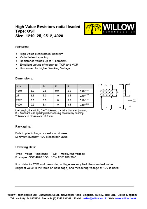
High Value Resistors radial leaded Type: GST Size: 1210, 25, 2512, 4020
Technical data – depending on size:
Size Power Rating P70(W) (P125 = 0W) Working Voltage U_, Ueff (V) trimmed untrimmed (Tol. > 5%) Ranges/Tolerances/TCR1)/VCR2) 1M – 100M >100M – 500M >100M – 1G >1G – 10G >10G – 100G >100G – 1T 0.5/1/2/5/10% TC 25/50/100 <50 ppm/V 2/5/10/20% TC 50/100/250 <100 ppm/V 5/10/20% TC 100/250 <100 ppm/V 5/10/20/30% TC 250/500 <500 ppm/V 5/10/20/30% TC 500/1000 <1000 ppm/V – 2/5/10% TC 50/100 <50 ppm/V 5/10/20% TC 100/250 <100 ppm/V 5/10/20% TC 100/250 <100 ppm/V 10/20/30% TC 250/500 <500 ppm/V 10/20/30% TC 500/1000 <1000 ppm/V – 0.5/…/10% TC 25/50/100 <10 ppm/V 1/2/5/10/20% TC 25/50/100 <25 ppm/V 1/2/5/10/20% TC 100/250 <25 ppm/V 2/5/10/20% TC 100/250 <100 ppm/V 5/10/20/30% TC 250/500 <250 ppm/V 10/20/30/50 TC 500/1000 <500 ppm/V 0.25/…/10% TC 25/50/100 <5 ppm/V 0.5/1/2/5/10/20% TC 25/50/100 <10 ppm/V 1/2/5/10/20% TC 25/50/100 <10 ppm/V 2/5/10/20% TC 50/100 <25 ppm/V 5/10/20/30% TC 100/250 <100 ppm/V 5/10/20/30% TC 250/500 <250 ppm/V 1210 0.5 25 0.7 2512 1.0 4020 2.0
日本SHINKO神港温控器JC系列 中文选型说明书
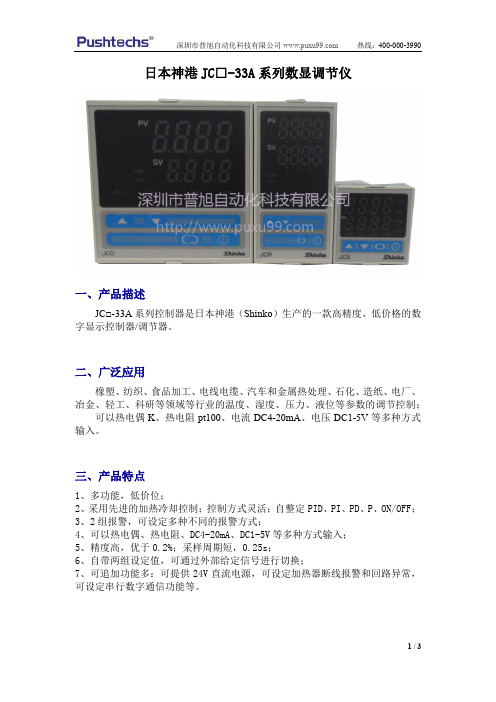
日本神港JC□-33A系列数显调节仪
一、产品描述
JC□-33A系列控制器是日本神港(Shinko)生产的一款高精度、低价格的数字显示控制器/调节器。
二、广泛应用
橡塑、纺织、食品加工、电线电缆、汽车和金属热处理、石化、造纸、电厂、冶金、轻工、科研等领域等行业的温度、湿度、压力、液位等参数的调节控制;
可以热电偶K、热电阻pt100、电流DC4-20mA、电压DC1-5V等多种方式输入。
三、产品特点
1、多功能,低价位;
2、采用先进的加热冷却控制;控制方式灵活;自整定PID、PI、PD、P、ON/OFF;
3、2组报警,可设定多种不同的报警方式;
4、可以热电偶、热电阻、DC4-20mA、DC1-5V等多种方式输入;
5、精度高,优于0.2%;采样周期短,0.25s;
6、自带两组设定值,可通过外部给定信号进行切换;
7、可追加功能多:可提供24V直流电源,可设定加热器断线报警和回路异常,可设定串行数字通信功能等。
四、日本shinko神港温控器JC系列简易选型表
注:更多相关产品、各行业温度控制系统解决方案详情、资料下载>>>>>>>>请进入普旭官网:
>>>>>>>>咨询热线:400-000-3990。
H2C资料

Motor Timer H2C DIN-sized(48x48,45x75mm)MotorTimer with Variable Time RangesFive time ranges are selectable per timer unit.Easy-to-monitor neon lamp for timing operationindication(for110,120,220,240VAC types only).Conforms to VDE0110Group C for creepagedistance.Easy-to-set large transparent knob and easy-to-read single pattern scale facilitate time setting.Equipped with timing operation indicator andmoving pointer.RC Ordering InformationOperation/resettingt InternaltiTerminal Time-limitt tInstantaneoust tModelp/gsystem connection contact contact Surfacemounting/track mountingFlush mountingTime-limit operation/ self-resetting Separate motorand clutchi8-pin roundsocketSPDT SPDT H2C-8H2C-8(withY92F-30adapter)se esett g a d c utcconnection11-pin roundsocket H2C H2C(withY92F-30adapter)Front screw H2C-F---Time-limit operation/ electric resetting 8-pin roundsocketSPDT---H2C-8R H2C-8R(withY92F-30adapter)e ect c esett g11-pin round socket SPDT H2C-R H2C-R(withY92F-30adapter)Front screw H2C-FR---Note:Specify both the model number and supply voltage when ordering.Accessories(Order Separately)Timer Track mounted socket(Back connecting socket(see note1)Solder terminal Screw terminal H2C-8,H2C-8R P2CF-08,PF085A PL08P3G-08H2C,H2C-R PF113A PL11P3GA-11Note:Track mounted socket can be used as a front connecting socket.SpecificationsTime RangesFive time ranges are available for each timer by turning the time range selector every 60degrees.Note:Rated time is displayed on the window.Time range codePosition of time range selectorA 1.25to 30s 7.5s to 3min 1.25to 30min 7.5min to 3hrs 1.25to 30hrsB 0.2to 6s 2to 60s 0.2to 6min 2to 60min 0.2to 6hrs C0.5to 12s5to 120s0.5to 12min5to 120min0.5to 12hrsRatingsItemH2CRated supply voltage 100,110,115,120,200,220,or 240VAC (50/60Hz)(see note 1)Operating voltage range 85%to 110%of rated supply voltage (see note 2)Power consumption Approx.3.5VAControl outputs 6A at 250VAC,resistive load (cos !=1)(see note 3)Note:1.The front panel of the timer is color coded to identify the following supply voltage classifications:100to 120V:Blue 200to 240V:Red Other classes:Black2.If the voltage continues to be applied after the set time has elapsed,the operating voltage range will change to between 90%and 110%of the rated voltage.3.The switching capacity of the control output is 6A at 250VAC (cos "=1).Refer to “Engineering Data”since the electrical service life of the built-in switch will change in such a case.CharacteristicsAccuracy of operating time #0.5%max.$#1%max.at 0.2to 6s for the time range code B or at 0.5to 12s for the time range code C)Setting error #2%max.Reset time0.5s max.Influence of voltage #1%max.Influence of temperature #2%max.Insulation resistance 100M %min.(at 500VDC)Dielectric strength2,500VAC,50/60Hz for 1min (between current-carrying and non-current-carrying parts)2,000VAC,50/60Hz for 1min (between contact and control circuit and between contacts of different polarities)1,000VAC,50/60Hz for 1min (between non-continuous contacts)Vibration resistance Destruction:10to 55Hz with 0.75-mm double amplitude Malfunction:10to 55Hz with 0.5-mm double amplitude Shock resistance Destruction:1,000m/s 2(approx.100G)Malfunction:150m/s 2(approx.15G)Ambient temperature Operating:--10&C to 50&C Storage:--25&C to 65&C Ambient humidity Operating:45%to 85%Life expectancyMechanical:10,000,000operations min.500,000operations min.(3A at 250VAC,resistive load at 1,800operations/h)Electrical:See “Engineering Data”Motor life expectancy 20,000hrsApproved standards UL (File No.E52800)WeightH2C series:approx.180g H2C-F series:approx.270gEngineering DataS w i t c h i n g o p e r a t i o ns(x 10)3Load current (A)S w i t c h i n g o p e r a t i o n s (x 10)3Load current (A)NomenclatureTime range selectorTiming operation indicatorRated voltage color codeOperationTiming ChartH2C-8ON-delay 8-pin Round SocketH2C(-F)H2C-(F)RRt:Resetting time H2C-8ROFF-delay 8-pin Round SocketRt:Resetting timeNote:For the types rated at 24and 48VAC,the timing operation indicator is not equipped.RtPower failureRt:Resetting time(see note)Rt:Resetting time(see note)Power failureDimensionsNote:All units are in millimeters unless otherwise indicated.H2C/H2C-R/H2C-8/H2C-8RFor Flush MountingFor a load current of 3A max.,dimension L becomes 3mm min.with an interval of 0mm between timers.For a load current of 6A max.,dimension L becomes 8mmmin.with an interval of 5mm between timers.H2C-F/H2C-FRMounting HolesMounting Height of TimerFor a load current of 1A max.,dimension L becomes 10mm min.with an interval of 0mm between timers.For a load current of 3A max.,dimension L becomes 15mm min.with an interval of 5mm between timers.For a load current of 6A max.,dimension L becomes 20mmmin.with an interval of 10mm between timers.Two,M4or 4.5dia.holes44.8x 44.8Accessories (Order Separately)Track Mounted/FrontConnecting Socket P2CF-08Two,4.5dia.holesTwo,4.5dia.or Two,M4Eight,M3.5x 7.5semMounting HolesTerminal Arrangement (Top View)Mounting Height of Timer with SocketPF085AMounting HolesTerminal Arrangement (Top View)Mounting Height of Timer with SocketFor a load current of 3A max.,dimen-sion L becomes 14mm min.with an in-terval of 0mm between timers.For a load current of 6A max.,dimen-sion L becomes 19mm min.withan in-terval of 5mm between timers.Eight,M3.5'7semsTwo,4.5dia.holesTwo,M4or 4.5dia.holesTop ViewPF113AMounting HolesTerminal Arrangement (Top View)Mounting Height of Timer with SocketFor a load current of 3A max.,dimension L becomes 14mm min.with an interval of 0mm between timers.For a load current of 6A max.,dimension L becomes 19mm min.withan interval of 5mm between timers.Two,M4or 4.5dia.holesEleven,M3.5'7semsP3GA-11Terminal Arrangement (Bottom View)Terminal Arrangement(Bottom View)Mounting Height of Timer with SocketP3G-08Mounting HolesTerminal Arrangement (Bottom View)MountingHeight of Timer with SocketPL11(Solder Terminals)Approx.20.5Two,3.5dia.or M3socket mounting holesTwo,2dia.holes35max.Back Connecting Socket PL08(Solder Terminals)Two,2dia.holesMounting HolesTerminal Arrangement (Bottom View)Mounting Height of Timer withSocketTwo,3.5dia.or 3M socket mountingholesBottom View27dia.Mounting Track(Meets DIN EN50022)PFP-100N/PFP-50N PFP-100N2Twelve,25'4.5elliptic holes(see note)(see note)Note:This dimension applied to PFP-50N.Note:A total of twelve,25x4.5elliptic holes are provided with6holes cut from each rail end at a pitch of10mm betweenholes.End PlatePFP-M PFP-SAdapter for Flush MountingY92F-30Note:The adapter can be mounted to the timer form any side ofthe timer housing since the adapter security notches areprovided on all four sides of the housing.H2C(with PF113A)H2C-FNote:For a load current of3A max.,a spacer and an endplate are not required.For a load current of6A,onespacer or an end plate is required.Note:For a load current of1A max.,a spacer and an endplate are not required.For a load current of3A max.,one spacer or an end plate is required.For a load cur-rent of6A max.two spacers or two end plates are re-quired.Timer Hold-down ClipsY92H-2(for PF085A/PF113AConnecting Socket)Y92H-1(for PL08/PL11ConnectingSocket)(Seenote)(Seenote)(See note)Time Setting RingY92A-Y1The time setting ring locks the time setting knob to store the set time to facilitate its resetting.A maximum of two time setting rings are connectable per timer.Protective CoverY92A-48BThe protective cover shields the front panel,particular-ly the time setting section,from dust,dirt,and water, as well as prevents the set value from beingaltereddue to accidental contact with the time setting knob.InstallationTerminal ArrangementH2C-8ON-delay8-pinRoundSocketH2C(-F)H2C-(F)RH2C-8ROFF-delay8-pin Round SocketPrecautionsHow to Change the Time RangeChange the positions of the time range selector with a flat-bladescrewdriver or an Allen wrench.CautionBe sure to turn the power off before changing the time specifi-cation.Changing the time range while the timer is in operation may cause a malfunction.How to Select Power FrequencyNoticePower frequencyBefore using the timer,set the frequency selector located at the rear panel to the proper power frequency (50or 60Hz).Note that if the frequency selector is set incorrectly,time mea-surement may not be performed accurately against the set time.How to Mount the Timer on Mounting TrackMountingFirst hook portion A of the timer to the mounting track,then depress the timer in direction B.DismountingPull out portion C with a round-blade screwdriver and remove the timer from the mounting track.BACElectrical SetThe motor and clutch do not need to be reset e the voltage applied to the clutch for resetting with the H2C-R.Do not allow power to be continuously applied to the motor and clutch for extended periods of time.OthersDo not turn the operation time setting knob beyond the range of the scale.To achieve higher accuracy in setting,measure the operation time while turning the operation time setting knob.The deviation and setting error for the operation time shows the per-cent of FS.The absolute value of the deviation and setting error will not change even if the set time is changed.The time specifications should therefore be selected to use the operation time as close to FS as possible.At high temperatures,the operation voltage will be 90%or less if voltage is applied continuously after timeout.Be sure to keep the voltage within the allowable voltage fluctuation range.ALL DIMENSIONS SHOWN ARE IN MILLIMETERS.To convert millimeters into inches,multiply by 0.03937.To convert grams into ounces,multiply by 0.03527.Cat.No.L007-E1-8!!。
特种文献

什么是特种文献
是指出版形式比较特殊的科技文献资料 出版形式比较特殊的科技文献资料。特种 出版形式比较特殊的科技文献资料 文献通常介于图书与期刊之间,似书非书, 似刊非刊,其内容广泛新颖,类型复杂多样, 涉及科学技术、生产生活的各个领域,出版 发行无统一规律,但具有重要的科技价值。 通常,特种文献主要包括:科技报告、专利 文献、标准文献、会议文献、学位论文、政 府出版物、产品资料、其他资料(如档案资 料、地图、乐谱等零散文献)等几种类型。
查看说明 书全文
特种文献检索
1. 2. 3. 4. 5.
专利知识与专利文献检索 标准知识与标准文献检索 科技报告检索 会议文献检索 学位论文检索
2.1 标准基础知识
2.1.1 什么是标准? 什么是标准? 标准文献是按照规定程序编制并经过一个公认的权威机构 批准的,供在一定范围内广泛而多次使用,包括一整套在 特定活动领域必须执行的规格、定额、规划、要求的技术 必须执行的规格、 必须执行的规格 定额、规划、 文件。标准涉及工农业、工程建设、交通运输、对外贸易 文件 和文化教育等领域,包括质量、安全、卫生、环境保护、 包装储运等多种类型。 标准文献是一种重要的科技出版物。 标准文献是一种重要的科技出版物。一个国家的标准文献 反映着该国的经济政策、技术政策、生产水平、加工工艺 水平、标准化水平、自然条件、资源情况等内容,对于全 面了解该国的工业发展情况,是一种重要的参考资料。
43 TY 体育 国家体育总局 44 WB 物资管理 中国物资流通协会 45 WH 文化 文化部 46 WJ 兵工民品 国防科工委(兵器) 47 WM 外经贸 对外经济贸易合作部 48 WS 卫生 卫生部 49 XB 稀土 国家计委稀土办公室 50 YB 黑色冶金 中国钢铁工业协会 51 YC 烟草 国家烟草专卖局 52 YD 通信 信息产业部(邮电) 53 YS 有色冶金 中国有色金属工业 协会 54 YY 医药 国家药品监督管理局 55 YZ 邮政 国家邮政局
执行标准
执行标准是国家规定的工业品必须执行或者推荐执行的标准。
标准可分为:国家标准、地方标准、行业标准、企业标准等等。
有的产品必须执行某种标准,有的产品可选择执行某种标准。
无论是强制的还是选择的,只要一个企业声明其产品所执行的标准,那么产品就必须接受标准的约束。
所以,商品上的“执行标准”可以是企业自行选择的,行政机关只能审查企业的产品是否执行合法的标准,并不证明企业的产品一定执行了该标准,但在产品检验时,应选择企业声明的执行标准。
序号行业标准名称行业标准代号主管部门1 农业NY 农业部2 水产SC 农业部3 水利SL 水利部4 林业LY 国家林业局5 轻工QB 国家轻工业局6 纺织FZ 国家纺织工业局7 医药YY 国家药品监督管理局8 民政MZ 民政部9 教育JY 教育部10 烟草YC 国家烟草专卖局11 黑色金属YB 国家冶金工业局12 有色冶金YS 国家有色金属工业局13 石油天然气ST 国家石油和化学工业局14 化工 HG 国家石油和化学工业局15 石油化工SH 国家石油和化学工业局16 建材 JC 国家建筑材料工业局17 地质矿产DZ 国土资源部18 土地管理TD 国土资源部19 测绘 CH 国家测绘局20 机械 JB 国家机械工业局21 汽车 QC 国家机械工业局22 民用航空MH 中国民航管理总局23 兵工民品WJ 国防科工委24 船舶 CB 国防科工委25 航空 HB 国防科工委26 航天 QJ 国防科工委27 核工业 EJ 国防科工委28 铁路运输TB 铁道部29 交通 JT 交通部30 劳动和劳动安全 LD 劳动和社会保障部31 电子 SJ 信息产业部32 通信 YD 信息产业部33 广播电影电视 GY 国家广播电影电视总局34 电力 DL 国家经贸委35 金融 JR 中国人民银行36 海洋 HY 国家海洋局37 档案 DA 国家档案局38 商检 SN 国家出入境检验检疫局39 文化 WH 文化部40 体育 TY 国家体育总局41 商业 SB 国家国内贸易局42 物资管理WB 国家国内贸易局43 环境保护HJ 国家环境保护总局44 稀土 XB 国家计发委稀土办公室45 城镇建设CJ 建设部46 建筑工业JG 建设部47 新闻出版CY 国家新闻出版署48 煤炭 MT 国家煤炭工业局49 卫生 WS 卫生部50 公共安全GA 公安部51 包装BB 中国包装工业总公司52 地震DB 国家地震局53 旅游LB 国家旅游局54 气象QX 中国气象局55 外经贸WM 对外经济贸易合作部56 海关HS 海关总署57 邮政YZ 国家邮政局注:行业标准分为强制性和推荐性标准。
CO25中文

启动 1. 将液压动力站的开关手柄置于 ON 的位置。 2. 每次在更换工作地点或是安装新锯片后,在开始切割前先使圆盘锯在工作转速下运转至少 一分钟。 适用于手持式: 将安全锁压入手柄,再逐渐扣动开关。 让锯片运转至少一分钟。 松开开关 适用于切割小车: 确保锯片的下沿离切割面至少 25mm。 逐渐扣动开关扳手。 让锯片运转至少一分钟,再松开开关。 如果发现有过度的震颤或其它故障,应立即停止工作进行检查,在问题解决前不要使用工具。
仅仅将动力站的开关手柄置于 OFF 的位置是不够安全的。
故障排除指南
如果出现性能下降的现象,可以参照下表排除故障。很多故障的排除工作需要经过培 训的史丹利技术工程师来完成。除了日常的维护外,液压工具的维修和服务要由史丹 利授权经销商来完成。 故障现象 工具不工作 原因 动力站液压系统开关手柄在 OFF 位置 液压软管连接不正确 液压系统失效 排除方法 将开关手柄扳到 ON 的位置 确保软管连接正确,接头连接牢固 检查液压动力站的输出流量和压力 是否正确 接头或软管阻断 机械故障 工具反转 软管反接 移除阻塞物 拆卸工具检查 按照快速接头上表明的液流方向连 接软管 马达处或与开 关阀连接处液 压油泄漏 油管密封失效 马达端面密封失效 更换 O 形密封圈 更换密封件
16
Stanley Hydraulic Tools
开关难于操作
液压软管连接错误
按照快速接头上表明的液流方向连 接软管
背压过高
如果背压超过 17 bar(250 psi) , 检查回油管是否有堵塞情况
工具转速过低
锯片选用不正确 液压流量不正确 安全阀压力设定过低
选用合适的锯片 调整液压流量为 26-34 lpm 调整安全阀压力为 145-155 bar
图书分类法

D - 世界史 (除美国史)
D 历史(总论)
DJK 东欧 (总论)
DA 英国
DK 俄罗斯、苏联、前苏联 - 波兰
代码的含义:
每一本书的索书号可以分为四至五个部份 例如:“GV”
“G”代表大类(G 代表地理、人类学、休闲活动)
“V”代表大类之下的纲目(GV 代表娱乐、休闲)
具体分类
A 总类
M 音乐
B 哲学、心理学及宗教
N 美术
C 历史学及相关科学总论
P 语言、文学
D 古代史及世界各国史
Q 科学
E 美洲历史
M - 音乐
M 音乐 ML 关于音乐的文献 MT 指导与学习
N - 艺术
N 视觉艺术 NA 建筑 NB 雕塑 NC 绘画、设计、插图 ND 油画 NE 书面媒体 NK 装饰艺术 NX 艺术总论
P - 语言与文学
P 文字学、语言学
PL 东亚、非洲和大洋洲语言与文学
PA 希腊语言与文学、拉丁语言与文学 PM 希柏里尔、印第安、和人工语言
B - 哲学, 心理学, 宗教
B 哲学(总论)
BQ 佛教
BC 逻辑
BR 基督教
BD 思辨哲学
BS 圣经
BF 心理学
BT 教义学
BH 美学
BV 实践神学
BJ 伦理学
BX 基督教教派
BL 宗教、神话、理性主义
BM 犹太教
BP 伊斯兰教、大同教、见神论 等
C - 历史学和相关科学总论
DH 低地国家 - 比荷卢
Panasonic SC-HC25 操作说明书

Dear CustomerThank you for purchasing this system.For optimum performance and safety, readthese instructions fully before you connect,operate or adjust this system.Keep this manual for future reference.Your system and the illustrations can lookdifferently.Do the procedures with the remotecontrol. You can also use the buttonson the main unit if they are the same.SUPPLIED ACCESSORIESPlease check and identify the supplied accessories.1 x AC mains lead1 x FM indoor antenna1 x AM loop antennaCAUTION!THIS PRODUCT UTILIZES A LASER.USE OF CONTROLS OR ADJUSTMENTSOR PERFORMANCE OF PROCEDURESOTHER THAN THOSE SPECIFIED HEREINMAY RESULT IN HAZARDOUS RADIATIONEXPOSURE.DO NOT OPEN COVERS AND DO NOT REPAIRYOURSELF. REFER SERVICING TO QUALIFIEDPERSONNEL.THIS UNIT IS INTENDED FOR USE INMODERATE CLIMATES.The socket outlet shall be installed near theequipment and easily accessible.The mains plug of the power supply cord shallremain readily operable.To completely disconnect this apparatus from theAC Mains, disconnect the power supply cord plugfrom AC receptacle.This product may receive radio interferencecaused by mobile telephones during use. Ifsuch interference is apparent, please increaseseparation between the product and the mobiletelephone.Product identification marking is located on thebottom of unit.PlacementSet the system up on an even surface away fromdirect sunlight, high temperatures, high humidity,and excessive vibration. These conditions candamage the cabinet and other components, therebyshortening the service life of the system.Place it at least 15 cm away from wall surfaces toavoid distortion and unwanted acoustical effects.Do not place heavy items on the system.VoltageDo not use high voltage power sources. This canoverload the system and cause a fire.Do not use a DC power source. Check the sourcecarefully when setting the system up on a ship orother place where DC is used.AC mains lead protectionEnsure the AC mains lead is connected correctlyand not damaged. Poor connection and leaddamage can cause fire or electric shock. Do notpull, bend, or place heavy items on the lead.Grasp the plug firmly when unplugging the lead.Pulling the AC mains lead can cause electric shock.Do not handle the plug with wet hands. This cancause electric shock.SAFETY PRECAUTIONSWARNING:TO REDUCE THE RISK OF FIRE, ELECTRICSHOCK OR PRODUCT DAMAGE,• DO NOT EXPOSE THIS APPARATUSTO RAIN, MOISTURE, DRIPPING ORSPLASHING AND THAT NO OBJECTSFILLED WITH LIQUIDS, SUCH AS VASES,SHALL BE PLACED ON THE APPARATUS.• USE ONLY THE RECOMMENDEDACCESSORIES.• DO NOT REMOVE THE COVER (OR BACK);THERE ARE NO USER SERVICEABLEPARTS INSIDE. REFER SERVICING TOQUALIFIED SERVICE PERSONNEL.CAUTION!• DO NOT INSTALL OR PLACE THIS UNIT INA BOOKCASE, BUILT-IN CABINET OR INANOTHER CONFINED SPACE. ENSURETHE UNIT IS WELL VENTILATED. TOPREVENT RISK OF ELECTRIC SHOCK ORFIRE HAZARD DUE TO OVERHEATING,ENSURE THAT CURTAINS AND ANY OTHERMATERIALS DO NOT OBSTRUCT THEVENTILATION VENTS.• DO NOT OBSTRUCT THE UNIT’SVENTILATION OPENINGS WITHNEWSPAPERS, TABLECLOTHS, CURTAINS,AND SIMILAR ITEMS.• DO NOT PLACE SOURCES OF NAKEDFLAMES, SUCH AS LIGHTED CANDLES, ONTHE UNIT.• DISPOSE OF BATTERIES IN ANENVIRONMENTALLY FRIENDLY MANNER.Foreign matterDo not let metal objects fall inside the system. Thiscan cause electric shock or malfunction.Do not let liquids get into the system. This cancause electric shock or malfunction. If this occurs,immediately disconnect the system from the powersupply and contact your dealer.Do not spray insecticides onto or into the system.They contain flammable gases which can ignite ifsprayed into the system.ServiceDo not attempt to repair this system by yourself.If sound is interrupted, indicators fail to light,smoke appears, or any other problem that is notcovered in these instructions occurs, disconnectthe AC mains lead and contact your dealer or anauthorised service centre. Electric shock or damageto the system can occur if the system is repaired,disassembled or reconstructed by unqualifiedpersons.Extend operating life by disconnecting the systemfrom the power source if it is not to be used for along time.Bottom of productMAINTENANCETo clean this system, wipe with a soft, dry cloth.• Never use alcohol, paint thinner or benzine to clean this system.• Before using chemically treated cloth, read the instructions that came with the cloth carefully.MPEG Layer-3 audio coding technology licensed from Fraunhofer IIS and Thomson.XWVUFront view– If you see this symbol –11 TROUBLESHOOTING GUIDEBefore requesting service, make the following checks. If you are in doubt about some of the check points, or if the solutions indicated do not solve the problem, consult your dealer for instructions.■USBThe USB mass storage device or the contents in it cannot be read.• The format of the USB mass storage device or the contents in it is/are not compatible with the system.• USB mass storage devices with storage capacity of more than 32 GB cannot work in some conditions.Slow operation of the USB mass storage device.• Large content size or large memory USB mass storage device takes longer time to read.The elapsed time shown is different from the actual play time.• Transfer the data to another USB mass storage device or backup the data and reformat the USB mass storage device.■Main unit displays“NO PLAY”• Examine the content. You can only play supported format.• This system can read and play up to 255 albums or folders (audio and non-audio).“F76” or “F61”• There is a power supply problem.“ERROR”• An incorrect operation was done. Read the instructions and try again.“NOT MP3/ERROR”• An unsupported MP3 format. The system will skip that track and play the next one.“VBR–”• The system cannot show the remaining play time for variable bit rate (VBR) tracks.“NODEVICE”• The iPod or iPhone is not connected. Examine the connection.Memory reset (Initialisation)When the following situations occur, refer to the instructions below to reset the memory:• There is no response when buttons are pressed.• You want to clear and reset the memory contents.To reset the memory1 Disconnect the AC mains lead.(Wait 3 minutes before you continue with step 2.)2 While you press and hold [1] on the main unit, connect the AC mains lead again.“– – – – – – – –” shows on the display panel.3 Release [1].All the settings are set back to the factory preset.It is necessary to set the memory items again.■Common problemsNo operations can be done with the remote control.• Examine that the battery is installed correctly.Sound is distorted or no sound.• Increase the volume.• Switch off the system, determine and correct the cause, then switch the system on again. It can be caused by straining of the speakers through excessive volume or power, and when using the system in a hot environment.A “humming” sound can be heard during playback.• An AC mains lead or fluorescent light is near the cables. Keep other appliances and cords away from the cables of this system.■DiscsDisplay not shown correctly. Playback does not start.• You have not put in the disc correctly. Put it in correctly.• Disc is dirty. Clean the disc.• Replace the disc if it is scratched, warped, or non-standard.• There is condensation. Let the system dry for 1 to 2 hours.The total number of tracks shown is incorrect.The disc cannot be read.Distorted sound is heard.• You put in a disc that the system cannot play. Change to a playable disc.• You put in a disc that has not been finalised.■RadioA beat sound is heard.• Switch off the TV or move it away from the system.A low hum is heard during AM broadcasts.• Move the antenna away from other cables and cords.■iPod or iPhoneYou cannot switch on the iPod or iPhone.• Examine that the battery of the iPod or iPhone is not depleted.• Switch off the iPod or iPhone and the system before you connect the iPod or iPhone. Connect the iPod or iPhone and try again.No sound.• Switch off the iPod or iPhone and remove from the system. Connect the iPod or iPhone to the system and switch it on and play it again.Manual presetting30 FM and 15 AM stations can be preset.PreparationPress [RADIO, EXT-IN] to select “FM” or “AM”.1 Press [3] or [5] to tune in to thestation.2 Press [PROGRAM].3 Press the numeric buttons to select a presetnumber.Do steps 1 through 3 again to preset more stations.The new station replaces any station that occupies the same preset number.Selecting a preset stationPress the numeric buttons, [2] or [6] (main unit: [2/3] or [5/6]) to select the preset station.AM allocation setting (by main unit only)This system can also receive AM broadcasts allocated in 10 kHz steps.1 Press [RADIO, EXT-IN] to select “FM” or“AM”.2 Press and hold [RADIO, EXT-IN].After a few seconds, the display panel shows the current minimum radio frequency. Release the button when the minimum frequency changes.• To go back to the initial setting, do the above steps again.• After you change the setting, preset frequencies are erased.Manual tuning1 Press [RADIO, EXT-IN] to select “FM” or“AM”.2 Press [3] or [5] to select the frequencyof the required station.To tune automatically, press and hold the button until the frequency starts changing quickly.To improve the sound qualityWhen “FM” is selected1 Press [RADIO MENU] to select “FM MODE”.2 Press [Y , U ] to select “MONO” and thenpress [OK].To cancel, select “ST”.• “MONO” is also cancelled when you change the frequency.• Turn off “MONO” for normal listening.When “AM” is selected1 Press [RADIO MENU] to select “B.PROOF”.2 Press [Y , U ] to select “BP 1” or “BP 2” andthen press [OK].Automatic presetting30 FM and 15 AM stations can be preset.PreparationPress [RADIO, EXT-IN] to select “FM” or “AM”.1 Press [OK] to select “LOWEST” or“CURRENT” frequency.2 Press [RADIO MENU] to select “A.PRESET” and then press [OK].“START?” is shown.3 Press [OK] to start presetting.6 RADIO10 REMOTE CONTROL CODEWhen other Panasonic equipment responds to the remote control of this system, change the remote control code for this system.PreparationPress [RADIO, EXT-IN] to select “AUX”.To set the code to “REMOTE 2”1 Press and hold [RADIO, EXT-IN] on themain unit and [2] on the remote control until “REMOTE 2” is shown.2 Press and hold [OK] and [2] for a minimum of4 seconds.To set the code to “REMOTE 1”1 Press and hold [RADIO, EXT-IN] on themain unit and [1] on the remote control until “REMOTE 1” is shown.2 Press and hold [OK] and [1] for a minimum of4 seconds.。
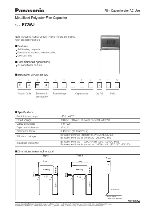
ECWJ18205JC中文资料
25.0
27.5
1
6.0
31.5
16.0
25.5
27.5
1
6.5
31.5
16.5
26.0
27.5
1
7.0
31.5
17.5
26.5
27.5
1
8.0
37.0
16.5
26.0
32.5
1
9.0
37.0
17.5
27.0
32.5
1
10.0
37.0
18.5
28.0
32.5
1
Design, Specifications are subject to change without notice. Ask factory for technical specifications before purchase and/or use. Whenever a doubt about satety arises from product, please inform us immediately for technical consultation without fail.
Cap.
(µF)
L
Dimensions (mm)
T
H
Type F
1.0
26.5
7.5
16.5
22.5
1
1.5
26.5
9.0
18.0
22.5
1
2.0
26.5
10.0
20.0
22.5
1
2.5
26.5
11.5
21.0
22.5
1
3.0
550C中文资料
550C中文资料关键信息项:1、资料名称:550C 中文资料2、资料用途:____________________________3、资料提供方:____________________________4、资料接收方:____________________________5、资料使用期限:____________________________6、资料保密要求:____________________________7、违约责任:____________________________8、争议解决方式:____________________________11 协议背景本协议旨在规范550C 中文资料的相关事宜,确保资料的合理使用、保护和传播。
111 资料的定义和范围本协议中所提及的550C 中文资料包括但不限于文字、图表、图像、音频、视频等与 550C 相关的各类中文形式的信息。
112 资料的用途资料接收方应仅将 550C 中文资料用于具体合法且明确的用途,不得用于其他任何未经授权的目的。
12 资料提供方的权利和义务121 提供方应确保所提供的 550C 中文资料的真实性、准确性和完整性。
122 提供方有权对资料接收方的使用情况进行监督和检查。
13 资料接收方的权利和义务131 接收方应按照协议约定的用途使用 550C 中文资料。
132 接收方有义务对资料进行妥善保管,采取合理的安全措施防止资料泄露、丢失或损坏。
133 未经提供方书面同意,接收方不得将资料转让、出售、出租或提供给任何第三方。
14 资料使用期限141 双方约定 550C 中文资料的使用期限为具体时间段。
142 在使用期限届满后,接收方应立即停止使用并按照提供方的要求归还或销毁资料。
15 资料保密要求151 接收方应对 550C 中文资料予以保密,不得向任何无关人员透露资料的内容。
152 接收方应采取必要的保密措施,如限制访问、加密存储等,以确保资料的保密性。
2C EDS系列工厂密封手动电动机起动开关和外壳 型号:2C EDS Series Factory
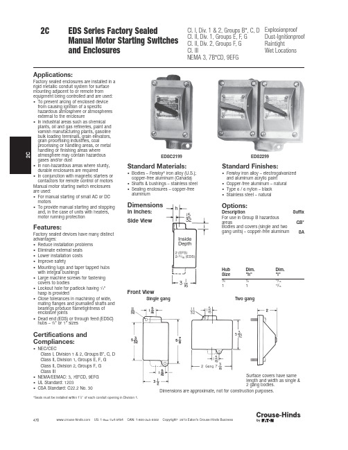
478 US: 1-866-764-5454 CAN: 1-800-265-0502 Copyright 2013 Eaton’s Crouse-Hinds Businessand EnclosuresCl.IIINEMA 3,7B*CD,9EFGWet LocationsEDSC2199EDS2299Applications:Factory sealed enclosures are installed in a rigid metallic conduit system for surface mounting adjacent to or remote fromequipment being controlled and are used:•To prevent arcing of enclosed device from causing ignition of a specifichazardous atmosphere or atmospheres external to the enclosure•In industrial areas such as chemical plants, oil and gas refineries, paint and varnish manufacturing plants, gasoline bulk loading terminals, grain elevators,grain processing industries, coalprocessing or handling areas, or metal handling or finishing areas where atmosphere may contain hazardous gases and/or dust•In non-hazardous areas where sturdy,durable enclosures are required•In conjunction with magnetic starters or contactors for remote control of motors Manual motor starting switch enclosures are used:•For manual starting of small AC or DC motors•To provide manual starting and stopping and, in the case of units with heaters,motor running protectionFeatures:Factory sealed devices have many distinctadvantages:•Reduce installation problems •Eliminate external seals •Lower installation costs •Improve safety•Mounting lugs and taper tapped hubs with integral bushings•Large machine screws for fastening covers to bodies•Lockout hole for padlock having 1/4"hasp is provided•Close tolerances in machining of wide,mating flanges and journalled shafts and bearings produce flametightness of enclosure joints•Dead end (EDS) or through feed (EDSC)hubs – 3/4" or 1" sizesCertifications and Compliances:•NEC/CECClass I, Division 1 & 2, Groups B*, C, D Class II, Division 1, Groups E, F, G Class II, Division 2, Groups F, G Class III•NEMA/EEMAC: 3, 7B*CD, 9EFG •UL Standard: 1203•CSA Standard: C22.2 No. 30Standard Materials:•Bodies – Feraloy ®iron alloy (U.S.);copper-free aluminum (Canada)•Shafts & bushings – stainless steel •Sealing enclosures – copper-free aluminumStandard Finishes:•Feraloy iron alloy – electrogalvanized and aluminum acrylic paint•Copper-free aluminum – natural •Type 6 / 6 nylon – black •Stainless steel – naturalOptions:Description Suffix For use in Group B hazardous areas GB*Bodies and covers (single and two gang units) – copper-free aluminum SADimensionsIn Inches:Side ViewFront ViewSingle gangTwo gangSurface covers have same length and width as single &2 gang bodies.Dimensions are approximate, not for construction purposes.*Seals must be installed within 1/" of each conduit opening in Division 1.Hub Size Dim."h"Dim."i"3/47/813/161115/16479 US: 1-866-764-5454 CAN: 1-800-265-0502 Copyright 2013 Eaton’s Crouse-Hinds Businessand EnclosuresOrdering InformationWith Allen-Bradley Bulletin 600 SwitchesMaximum HP RatingsPoles 115–230Volts AC 115–230Volts DCCat.#11 hp A B BUL 600 TOX421 hp 3/4hpA B BUL 600 TOX5Poles Hub Size in.Dead end Cat.#Through feed Cat.#Single Gang13/4EDS2199 ➀EDSC2199 ➀1EDS3199 ➀EDSC3199 ➀23/4EDS21100 ➀EDSC21100 ➀1EDS31100 ➀EDSC31100 ➀Two Gang 13/4EDS2299 ➀EDSC2299 ➀1EDS3299 ➀EDSC3299 ➀23/4EDS22100 ➀EDSC22100 ➀1EDS32100 ➀EDSC32100 ➀Heater Table (Allen-Bradley)Max. Motor Full-Load Amps Eaton'sCrouse-Hinds Symbol Number Max. Motor Full-Load Amps Eaton'sCrouse-Hinds Symbol Number 0.17P1 2.92P220.21P2 3.09P230.25P3 3.32P240.32P4 3.77P250.39P5 4.16P260.46P6 4.51P270.57P7 4.93P280.71P8 5.43P290.79P9 6.03P300.87P10 6.83P310.98P117.72P321.08P128.24P331.19P138.9P341.30P149.6P351.43P1510.8P361.58P1612.0P371.75P1713.5P381.88P1815.2P392.13P192.40P202.58P21With General Electric SwitchesMaximum HP RatingsPoles 115–230Volts AC 115Volts DC 230Volts DC Cat.#1 1 hp 1 hp 1/4hp GE CR101 Y 21 hp1 hp1 hpGE CR101 HPoles Hub Sizein.Dead end Cat.#Through feed Cat.#Single Gang13/4EDS21093 ➀EDSC21093 ➀1EDS31093 ➀EDSC31093 ➀23/4EDS21094 ➀EDSC21094 ➀1EDS31094 ➀EDSC31094 ➀Two Gang 13/4EDS22093 ➀EDSC22093 ➀1EDS32093 ➀EDSC32093 ➀23/4EDS22094 ➀EDSC22094 ➀1EDS32094 ➀EDSC32094 ➀Heater Table (General Electric)Max. Motor Full-Load Amps Eaton'sCrouse-Hinds Symbol Number Max. Motor Full-Load Amps Eaton'sCrouse-Hinds Symbol Number .48G2 3.01G22.53G3 3.27G23.58G4 3.56G24.65G5 3.88G25.71G6 4.22G26.78G7 4.60G27.86G8 5.00G28.95G9 5.43G291.04G10 5.90G301.14G11 6.41G311.25G12 6.98G321.37G137.60G331.49G148.25G341.63G158.95G351.78G169.75G361.95G1710.6G372.13G1811.4G382.32G1912.5G392.53G2013.6G402.76G2114.8G4116.0G42Cl.IIINEMA 3,7B*CD,9EFGWet Locations*Add GB suffix. Seals must be installed within 1/" of each conduit opening for Group B usage.➀Includes one interchangeable heater. Select heater from the table below individual listings and use symbol number as second section of the Cat. No. Example: EDS2199-P5. Insert symbol 0 (zero) to omit heater.These heaters are for motors rated 40°C continuously. For motors rated 50°C or 55°C, multiply full load motor current by 0.9 and use this value to select heaters. Symbol 0 (zero) must be used to indicate heater omitted.480 US: 1-866-764-5454 CAN: 1-800-265-0502 Copyright 2013 Eaton’s Crouse-Hinds BusinessHeater Table (Cutler-Hammer)Max. Motor Full-Load Amps Eaton'sCrouse-Hinds Symbol Number Max. Motor Full-Load Amps Eaton'sCrouse-Hinds Symbol Number .43W 1 2.95W21.48W 2 3.27W22.53W 3 3.59W23.58W 4 3.99W24.64W 5 4.39W25.71W 6 4.79W26.78W 7 5.26W27.87W 8 5.83W28.95W 9 6.39W291.03W107.03W301.15W117.74W311.27W128.46W321.35W139.35W331.51W1410.30W341.67W1511.35W351.83W1612.47W361.99W1713.67W372.23W1815.12W382.47W1916.00W392.71W20➀Includes one interchangeable heater. Select heater from the table below individual listings and use symbol number as second section of the Cat. No. Example: EDS2199-P5. Insert symbol 0 (zero) to omit heater.These heaters are for motors rated 40°C continuously. For motors rated 50°C or 55°C, multiply full load motor current by 0.9 and use this value to select heaters. Symbol 0 (zero) must be used to indicate heater omitted.*Add GB suffix. Seals must be installed within 1/" of each conduit opening for Group B usage.2CEDS Series Factory Sealed Manual Motor Starting Switches and EnclosuresCl.I,Div.1 & 2,Groups B*,C,D Cl.II,Div.1,Groups E,F,G Cl.II,Div.2,Groups F,G Cl.IIINEMA 3,7B*CD,9EFGExplosionproof Dust-Ignitionproof Raintight Wet LocationsWith Cutler-Hammer SwitchesMaximum HP RatingsPoles 120–240Volts AC 32Volts DC 120Volts DC240Volts DC Cat.#11 hp 1/4hp 1/4hp 1/4hp WEST MST0121 hp1/4hp 1 hp 3/4hp WEST MST02Poles Hub Size in.Dead end Cat.#Through feed Cat.#Single Gang13/4EDS21101 ➀EDSC21101 ➀1EDS31101 ➀EDSC31101 ➀23/4EDS21102 ➀EDSC21102 ➀1EDS31102 ➀EDSC31102 ➀Two Gang13/4EDS22101 ➀EDSC22101 ➀1EDS32101 ➀EDSC32101 ➀23/4EDS22102 ➀EDSC22102 ➀1EDS32102 ➀EDSC32102 ➀。
JCC产品说明书
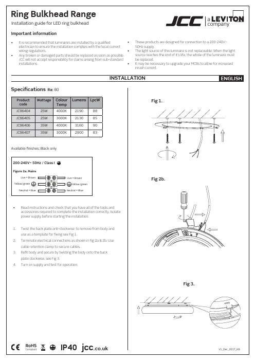
companyaImportant information•It is recommended that luminaires are installed by a qualifiedelectrician to ensure the installation complies with the local currentwiring regulations.•Any broken or damaged parts should be replaced as soon as possible. JCC will not accept responsibility for claims arising from sub-standardinstallations.• These products are designed for connection to a 200-240V~ 50Hz supply.• The light source of this luminaire is not replaceable: When the light source reaches the end of it’s life, the whole of the luminaire must be replaced.• It may be necessary to upgrade your MCBs to allow for increased inrush current.INSTALLATIONENGLISH•R ead instructions and check that you have all of the tools and accessories required to complete the installation correctly. Isolate power supply before starting the installation.Specifications Ra: 80RoHSCompliantIP40jcc V1_Dec_2017_KBFigure 2a. MainsLive = Brown Yellow/greenNeutral = BlueLive = BrownYellow/green Neutral = BlueAvailable finishes: Black onlyInstallation guide for LED ring bulkhead 200-240V~ 50Hz / Class IProduct code Wattage Colour TempLumens LpcWJC9640425W 4000K 219088JC9640525W 3000K 213085JC9640635W 4000K 316090JC9640735W3000K290083Ring Bulkhead Range1. Twist the back plate anti-clockwise to remove from body and use as a template for fixing see Fig 1.2. Terminate electrical connections as shown in Fig 2a & 2b. Use cable retention clamp to secure cables.3. Refit body and secure by twisting the body onto the back plate clockwise, see Fig 3.4.Turn on supply and test for operation.Fig 1.Fig 2b.Fig 3.Profile & DimensionsAll dimensions in millimetresJCC Lighting Products Ltd., Innovation Centre, Beeding Close, Southern Cross Trading Estate, Bognor Regis, West Sussex, PO22 9TS , United kingdomTechnical Support: +44(0)1243 838986 Customer Services: +44(0)1243 838999Important warranty informationThese luminaires are supported by a 3 year warranty; which must be registered online at /warranty.The installer will be asked to provide the following information, which is detailed on a label attached to the luminaire’s chassis: Product Code/Batch Code.Ø3005140Ø400685425W35W。
接触器CT25
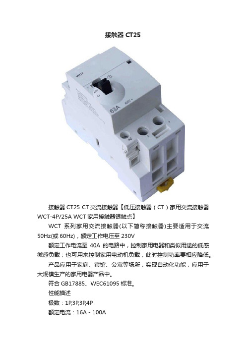
接触器CT25接触器CT25 CT交流接触器【低压接触器(CT)家用交流接触器WCT-4P/25A WCT家用接触器银触点】WCT系列家用交流接触器(以下简称接触器)主要适用于交流50Hz(或60Hz),额定工作电压至230V额定工作电流至40A的电路中,控制家用电器和类似用途的低感微感负载;也可用来控制家用电动机负载,此时控制功率要相应降低。
产品应用于家庭、宾馆、公寓等场所,实现自动化功能,应用于大规模生产的家用电器产品中。
符合GB17885、WEC61095标准。
性能描述极数:1P,3P,3P,4P额定电流:16A-100AWCT-4P/25A WCT家用接触器银触点二、【低压接触器(CT)家用交流接触器WCT-4P/25A WCT家用接触器银触点】优势模块化的WCT接触器用于控制单相和三相回路,电流可以达到100安培。
并且WCT可拼装以下附件:a WAWCTS+f 指示主触点状态b AWCTc附件让WCT接触器可接受脉冲信号三、【低压接触器(CT)家用交流接触器WCT-4P/25A WCT家用接触器银触点】应用范围使用模块化WCT 系列接触器实现楼宇,第三产业和工业等部门的自动化:照明(发光标志、商店橱窗、安全照明等)取暖、热泵、加热炉民用热水小型设备电机(泵、风机、伸缩门、车库门等)家用交流负荷的卸载和恢复四、【低压接触器(CT)家用交流接触器WCT-4P/25A WCT家用接触器银触点】型号WCT 3P 16A 1NO+1NC 230V AC WCT 3P 63A 2NO 230V AC WCT 3P 16A 2NO 230V AC WCT 3P 63A 3NO 230V ACWCT 1P 40A 1NO 230V AC WCT 3P 63A 3NO 230V ACWCT 3P 40A 2NO 230V AC WCT 3P 63A 2NO+1NC 230V AC WCT 3P 40A 2NC 230V AC WCT 4P 63A 4NO 230V ACWCT 3P 40A 3NO 230V AC WCT 4P 63A 4NC 230V ACWCT 4P 40A 4NO 230V AC WCT 4P 63A 2NO+2NC 230V AC WCT 4P 40A 4NC 230V AC WCT 3P 100A 2NO 230V ACWCT 4P 40A 2NO+2NC 230V AC WCT 4P 100A 4NO 230V ACWCT 3P 60A 2NO 230V AC WCT 3P 40A 2NO 24V ACWCT 3P 60A 3NO 230V AC WCT 4P 40A 4NO 24V ACWCT 4P 60A 4NO 230V AC WCT 4P 40A 4NC 24V ACWCT 4P 60A 4NC 230V AC WCT 3P 63A 2NO 24V ACWCT 4P 63A 4NO 24V AC WCT 4P 63A 4NC 24V AC五、其他说明性能优势:模块化的CT接触器用于控制单相和三相回路,电流可以达到100安培。
SFW资料
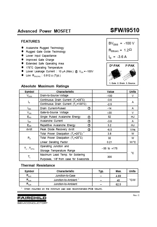
SFW/I9510BVDSS= -100 VRDS(on)= 1.2ID= -3.6 A-100-3.6-2.5-14±3052-3.63.2-6.53.8320.21-55 to +1753004.694062.5------Ωn Avalanche Rugged Technologyn Rugged Gate Oxide Technologyn Lower Input Capacitancen Improved Gate Chargen Extended Safe Operating Arean175o C Operating Temperaturen Lower Leakage Current : 10µA(Max.) @ V DS= -100Vn Low R DS(ON) : 0.912 Ω(Typ.)Advanced Power MOSFETThermal ResistanceJunction-to-CaseJunction-to-AmbientJunction-to-AmbientRθJCRθJARθJAo C/WCharacteristic Max.Units Symbol Typ.FEATURESD2-PAK1. Gate2. Drain3. Source132123I2-PAK**When mounted on the minimum pad size recommended (PCB Mount).Absolute Maximum RatingsDrain-to-Source VoltageContinuous Drain Current (T C=25o C)Continuous Drain Current (T C=100o C)Drain Current-PulsedGate-to-Source VoltageSingle Pulsed Avalanche EnergyAvalanche CurrentRepetitive Avalanche EnergyPeak Diode Recovery dv/dtTotal Power Dissipation (T A=25o C)Total Power Dissipation (T C=25o C)Linear Derating FactorOperating Junction andStorage Temperature RangeMaximum Lead Temp. for SolderingPurposes, 1/8”from case for 5-secondsCharacteristic Value Units SymbolI DMV GSE ASI ARE ARdv/dtP DI DT J , T STGT LAVmJAmJV/nsWWW/o CAo C V DSS V*O1O2O3O1O1Rev. CSFW/I9510-100 ---2.0 -----------0.1 ----------50 17 10 20 25 12 91.54.3-----4.0-100100-10-1001.2--33580253050603510----1.8260------1000.35-3.6-14-3.8----Notes ;Repetitive Rating : Pulse Width Limited by Maximum Junction TemperatureL=6.0mH, IAS=-3.6A, VDD=-25V, RG=27Ω*, Starting T J =25o CISD-3.6A,di/dt300A/µs, VDDBVDSS, Starting TJ=25o CPulse Test : Pulse Width = 250µs, Duty Cycle 2%Essentially Independent of Operating Temperature_<O1O2O3O4O5_<_<_<P-CHANNELPOWER MOSFETElectrical Characteristics (TC=25o C unless otherwise specified)Drain-Source Breakdown VoltageBreakdown Voltage Temp.Coeff.Gate Threshold VoltageGate-Source Leakage , ForwardGate-Source Leakage , ReverseCharacteristicSymbol Max.UnitsTyp.Min.Test ConditionStatic Drain-SourceOn-State ResistanceForward TransconductanceInput CapacitanceOutput CapacitanceReverse Transfer CapacitanceTurn-On Delay TimeRise TimeTurn-Off Delay TimeFall TimeTotal Gate ChargeGate-Source ChargeGate-Drain(“Miller”) Chargeg fsC issC ossC rsst d(on)t rt d(off)t fQ gQ gsQ gdBV DSS∆BV/∆T JV GS(th)R DS(on)I GSSI DSSVV/o CVnAµAΩpFnsnC--------------------------V GS=0V,I D=-250µAI D=-250µA See Fig 7V DS=-5V,I D=-250µAV GS=-20VV GS=20VV DS=-100VV DS=-80V,T C=150o CV GS=-10V,I D=-1.8AV DS=-40V,I D=-1.8AV DD=-50V,I D=-3.6A,R G=24See Fig 13V DS=-80V,V GS=-10V,I D=-3.6ASee Fig 6 & Fig 12 Drain-to-Source Leakage CurrentV GS=0V,V DS=-25V,f =1MHzSee Fig 5Source-Drain Diode Ratings and CharacteristicsContinuous Source CurrentPulsed-Source CurrentDiode Forward VoltageReverse Recovery TimeReverse Recovery ChargeI SI SMV SDt rrQ rrCharacteristicSymbol Max.UnitsTyp.Min.Test Condition----------AVnsµCIntegral reverse pn-diodein the MOSFETT J=25o C,I S=-3.6A,V GS=0VT J=25o C,I F=-3.6Adi F/dt=100A/µsΩO4O5O4O4O5O4O4O4O1SSFW/I951010-11010110-110101@ N o t e s :1. 250 µsP u l s e T e s t 2. T C= 25 o C V GS Top : - 15 V- 10 V - 8.0 V - 7.0 V - 6.0 V - 5.5 V - 5.0 V Bottom : - 4.5 V-I D , D r a i n C u r r e n t [A ]-V D S , D r a i n -S o u r c e V o l t a g e [V ]24681010-11010125 o C175 oC - 55 o C@ N o t e s :1. V GS = 0 V2. V DS = -40 V3. 250 µs P u l s e T e s t -I D , D r a i n C u r r e n t [A ]-V G S , G a t e -S o u r c e V o l t a g e [V ]0.51.01.52.02.53.03.54.010-110101175o C 25o C @ N o t e s :1. V GS= 0 V 2. 250 µs P u l s e T e s t -I D R , R e v e r s e D r a i n C u r r e n t [A ]-V S D , S o u r c e -D r a i n V o l t a g e [V ]101010100200300400500C is s = C gs + C gd ( C ds = s h o r t e d )C os s = C ds + C gd C rs s = C gd@ N o t e s :1. V GS = 0 V2. f = 1 M H zC rs sC os s C is sC a p a c i t a n c e [p F ]-V D S , D r a i n -S o u r c e V o l t a g e [V ]246810121412345@ N o t e : T J= 25 oC V GS= -20 V V GS= -10 V R D S (o n ) , [Ω]D r a i n -S o u r c e O n -R e s i s t a n c e-I D , D r a i n C u r r e n t [A ]0246810510V DS= -80 V V DS = -50 V V DS= -20 V @ N o t e s : I D=-3.6 A -V G S , G a t e -S o u r c e V o l t a g e [V ]Q G , T o t a l G a t e C h a r g e [n C ]P-CHANNEL POWER MOSFETFig 1. Output CharacteristicsFig 2. Transfer CharacteristicsFig 6. Gate Charge vs. Gate-Source VoltageFig 5. Capacitance vs. Drain-Source VoltageFig 4. Source-Drain Diode Forward VoltageFig 3. On-Resistance vs. Drain CurrentSFW/I9510-75-50-252550751001251501752000.00.51.01.52.02.5@ N o t e s :1. V GS= -10 V 2. I D= -1.8 A R D S (o n ) , (N o r m a l i z e d )D r a i n -S o u r c e O n -R e s i s t a n c eT J , J u n c t i o n T e m p e r a t u r e [oC ]1010110210-110010110 m s D C1 m s 0.1 m s @ N o t e s :1. T C =25 oC 2. T J= 175 o C 3. S i n g l e P u l s eO p e r a t i o n i n T h i s A r e ai s L i m i t e d b y R DS(on)-I D , D r a i n C u r r e n t [A ]-V D S , D r a i n -S o u r c e V o l t a g e [V ]-75-50-252550751001251501752000.80.91.01.11.2@ N o t e s :1. V GS= 0 V 2. I D= -250 µA -B V D S S , (N o r m a l i z e d )D r a i n -S o u r c e B r e a k d o w n V o l t a g eT J , J u n c t i o n T e m p e r a t u r e [oC ]2550751001251501751234-I D , D r a i n C u r r e n t [A ]T c , C a s e T e m p e r a t u r e [o C ]10-510-410-310-210-110010110-1100single pulse0.20.10.010.020.05D=0.5@ Notes :1. Z θJ C (t)=4.69 o C/W Max.2. Duty Factor, D=t 1/t 23. T J M -T C =P D M *Z θJ C (t)Z θJ C(t ) , T h e r m a l R e s p o n s et 1 , Square Wave Pulse Duration [sec]P-CHANNELPOWER MOSFETFig 7. Breakdown Voltage vs. TemperatureFig 8. On-Resistance vs. TemperatureFig 11. Thermal ResponseFig 10. Max. Drain Current vs. Case TemperatureFig 9. Max. Safe Operating AreaP DM.t 1.t 2.SFW/I9510P-CHANNEL POWER MOSFETFig 12. Gate Charge Test Circuit & WaveformFig 13. Resistive Switching Test Circuit & WaveformsFig 14. Unclamped Inductive Switching Test Circuit & WaveformsE AS =L L I AS 2----21--------------------BV DSS --V DDBV DSSV inV out10%90%t d(on)t rt ont offt d(off)t fChargeV GS-10VQ gQ gs Q gdVary t p to obtain required peak I D-10VV DDCL LV DSI DR Gt pDUTBV DSSt pV DDI ASV DS (t)I D (t)TimeV DD( 0.5 rated V DS )-10VV out V inR LDUTR G-3mAV GSCurrent Sampling (I G )ResistorCurrent Sampling (I D )ResistorDUTV DS300nF50K 200nF12VSame Type as DUT“Current Regulator ”R 1R 2ΩSFW/I9510P-CHANNEL POWER MOSFETFig 15. Peak Diode Recovery dv/dt Test Circuit & WaveformsDUTV DS+--LI SDriverV GSR GCompliment of DUT(N-Channel)V GS•dv/dt controlled by “R G ”•I S controlled by Duty Factor “D”V DD10VV GS ( Driver )I S ( DUT )V DS ( DUT )V DDBody DiodeForward Voltage DropV fI FM , Body Diode Forward CurrentBody Diode Reverse CurrentI RMBody Diode Recovery dv/dtdi/dtD =Gate Pulse Width Gate Pulse Period--------------------------DISCLAIMERFAIRCHILD SEMICONDUCTOR RESERVES THE RIGHT TO MAKE CHANGES WITHOUT FURTHER NOTICE TO ANY PRODUCTS HEREIN TO IMPROVE RELIABILITY , FUNCTION OR DESIGN. FAIRCHILD DOES NOT ASSUME ANY LIABILITY ARISING OUT OF THE APPLICATION OR USE OF ANY PRODUCT OR CIRCUIT DESCRIBED HEREIN; NEITHER DOES IT CONVEY ANY LICENSE UNDER ITS PATENT RIGHTS, NOR THE RIGHTS OF OTHERS.TRADEMARKSThe following are registered and unregistered trademarks Fairchild Semiconductor owns or is authorized to use and is not intended to be an exhaustive list of all such trademarks.LIFE SUPPORT POLICYFAIRCHILD S PRODUCTS ARE NOT AUTHORIZED FOR USE AS CRITICAL COMPONENTS IN LIFE SUPPORTDEVICES OR SYSTEMS WITHOUT THE EXPRESS WRITTEN APPROVAL OF FAIRCHILD SEMICONDUCTOR CORPORATION.As used herein:1. Life support devices or systems are devices orsystems which, (a) are intended for surgical implant intothe body, or (b) support or sustain life, or (c) whosefailure to perform when properly used in accordancewith instructions for use provided in the labeling, can be reasonably expected to result in significant injury to the user.2. A critical component is any component of a life support device or system whose failure to perform can be reasonably expected to cause the failure of the life support device or system, or to affect its safety or effectiveness.PRODUCT STATUS DEFINITIONS Definition of Terms Datasheet Identification Product Status DefinitionAdvance InformationPreliminaryNo Identification Needed Obsolete This datasheet contains the design specifications for product development. Specifications may change in any manner without notice.This datasheet contains preliminary data, andsupplementary data will be published at a later date.Fairchild Semiconductor reserves the right to make changes at any time without notice in order to improve design.This datasheet contains final specifications. Fairchild Semiconductor reserves the right to make changes at any time without notice in order to improve design.This datasheet contains specifications on a product that has been discontinued by Fairchild semiconductor.The datasheet is printed for reference information only.Formative or In Design First ProductionFull ProductionNot In ProductionImpliedDisconnect ISOPLANARLittleFETMicroFETMicroPakMICROWIREMSXMSXProOCXOCXProOPTOLOGIC âOPTOPLANARFACT FACT Quiet Series FAST âFASTr FRFET GlobalOptoisolator GTO HiSeCI 2CRev. I1ACEx ActiveArray Bottomless CoolFET CROSSVOLT DOME EcoSPARK E 2CMOS TM EnSigna TMPACMANPOP Power247 PowerTrench âQFET QS QT Optoelectronics Quiet Series RapidConfigure RapidConnect SILENT SWITCHER âSMART START SPMStealthSuperSOT -3SuperSOT -6SuperSOT -8SyncFET TinyLogic TruTranslation UHC UltraFET âVCXAcross the board. Around the world. The Power FranchiseProgrammable Active Droop元器件交易网。
HS-25T

HS-25D 电气机械设备清洗剂产品说明HS-25D由多种精制溶剂有效复配而成,可迅速清除各种电气设备、机械设备各部位的油污、粉尘、泥土和水分等污物。
能延长设备的使用寿命,预防设备故障,是保障设备正常运转,提高生产效率的极佳保养品。
HS-25D具有以下显著特点:★HS-25D完全不燃烧,没有像稀料、汽油等物那样的引火危险性,可以在有明火的环境中使用,安全性高。
★HS-25D挥发迅速,既能彻底溶解油污,又能完全挥发,不留残迹,不影响设备的正常使用。
★HS-25D复合多种强力除油溶剂,对多种成分的油污均有极好的清洗效果。
★HS-25D绝不含有四氯化碳、苯类化合物、三氯乙烯等毒性物质,毒性小,空气中最高允许浓度可达400ppm以上,而四氯化碳在空气中最高允许浓度仅为10ppm。
★HS-25D不含有被国家有关法令禁止使用的臭氧层消耗物质,符合国家环保要求,而四氯化碳则属此类被禁止的臭氧层消耗物质。
因而,HS-25D除具有不燃性、挥发速度快、除油能力强等四氯化碳所具有的全部优点外,还具有毒性小、环保性好等优点,是一种极佳的四氯化碳替代清洗剂。
用途广泛用于发电、输变电、石油、化工、内燃机车、船舶、汽车、冶金、造纸、印刷、机械制造、塑料、采矿、电讯等行业。
用于发电机、电动机、电气柜、电焊机、发动机、输变电设备、配电室设备、电动工具、电控系统、仪器仪表、空调机组、信号系统、油过滤器、液压装置、铁链机构、起重机械、变速箱及齿轮、轴承、钻井采油设备、输油管线阀门等设备的清洗。
使用方法1、喷洗使用本公司HS-901专用喷枪,接上0.4-0.6MPa的压缩空气,先用压缩空气将设备表面的尘土、铁屑等杂物吹除,然后用HS-901喷枪吸进HS-25D产品进行喷洗至清洁后,再用压缩空气吹干。
亦可采用手动喷壶进行喷洗。
2、浸洗各种小型设备、机具、零部件可直接浸泡于HS-25D产品中,数分钟捞出自然风干或用压缩空气吹干。
3、擦刷对无需喷洗或浸洗的情况,可用抹布沾HS-25D进行擦洗或用刷子刷洗。
国标哈氏合金c-2000
国标哈氏合金c-2000
国标哈氏合金C-2000是一种镍基耐蚀合金,具有优异的耐腐
蚀性能。
它主要由镍(Ni)、铬(Cr)、钼(Mo)和铜(Cu)等元素组成。
C-2000合金具有优异的耐腐蚀性能,尤其在高
温和强腐蚀环境下表现出色。
它广泛应用于化工、石油、制药、造纸等领域的设备和管道中,用于处理腐蚀性介质。
C-2000合金具有以下特点:
1. 高耐腐蚀性:C-2000合金在广泛的腐蚀介质中表现出优异
的耐蚀性能,包括强酸、强碱、盐溶液和氯化物等。
2. 高温强度:C-2000合金具有良好的高温强度和耐热性,能
够在高温环境下保持其力学性能和结构稳定性。
3. 抗氧化性:C-2000合金具有良好的抗氧化性,能够在高温
下抵御氧化物的侵蚀。
4. 易加工性:C-2000合金具有良好的可加工性,能够通过冷
加工和热加工等工艺进行成型和加工。
总之,国标哈氏合金C-2000是一种具有优异耐蚀性能的镍基
耐蚀合金,广泛应用于化工、石油等行业的设备和管道中,用于处理腐蚀性介质。
潘通 CLT25F-C20 扁平开槽波纹软管 说明书
Add to Favorite Product List
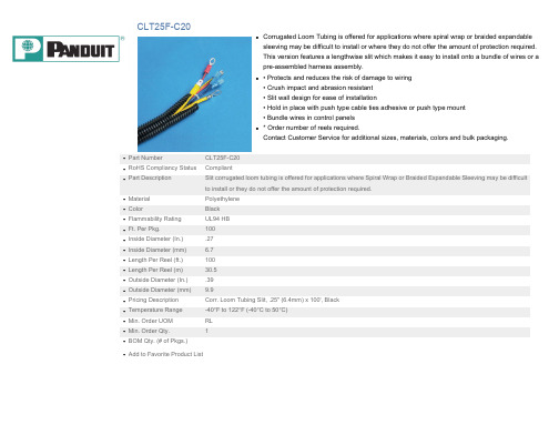
Material Color Flammability Rating Ft. Per Pkg. Inside Diameter (In.) Inside Diameter (mm) Length Per Reel (ft.) Length Per Reel (m) Outside Diameter (In.) Outside Diameter (mm) Pricing Description Temperature Range Min. Order UOM Min. Order Qty. BOM Qty. (# of Pkgs.) Loom Tubing is offered for applications where spiral wrap or braided expandable sleeving may be difficult to install or where they do not offer the amount of protection required. This version features a lengthwise slit which makes it easy to install onto a bundle of wires or a pre-assembled harness assembly.