REC5-0505SRWZH6中文资料
FSDM0565RWDTU中文资料
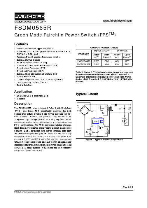
©2005 Fairchild Semiconductor CorporationRev.1.0.5Features•Internal Avalanche Rugged Sense FET•Advanced Burst-Mode operation consumes under 1 W at 240V AC & 0.5W load•Precision Fixed Operating Frequency (66kHz)•Internal Start-up Circuit•Pulse by Pulse Current Limiting•Abnormal Over Current Protection (AOCP)•Over V oltage Protection (OVP)•Over Load Protection (OLP)•Internal Thermal Shutdown Function (TSD)•Auto-Restart Mode•Under V oltage Lock Out (UVLO) with hysteresis •Low Operating Current (2.5mA)•Built-in Soft StartApplication•SMPS for LCD monitor and STB •AdaptorDescriptionThe FSDM0565R is an integrated Pulse Width Modulator (PWM) and Sense FET specifically designed for high performance offline Switch Mode Power Supplies (SMPS)with minimal external components. This device is an integrated high voltage power switching regulator which combine an avalanche rugged Sense FET with a current mode PWM control block. The PWM controller includes integrated fixed frequency oscillator, under voltage lockout, leading edge blanking (LEB), optimized gate driver, internal soft start,temperature compensated precise current sources for a loop compensation and self protection circuitry. Compared with discrete MOSFET and PWM controller solution, it can reduce total cost, component count, size and weight simultaneously increasing efficiency, productivity, and system reliability. This device is a basic platform well suited for cost effective designs of flyback converters.Table 1.Notes: 1. Typical continuous power in a non-ven-tilated enclosed adapter measured at 50°C ambient. 2. Maximum practical continuous power in an open frame design at 50°C ambient. 3. 230 VAC or 100/115 VAC with doubler.Typical CircuitOUTPUT POWER TABLEPRODUCT 230VAC ±15%(3)85-265VAC Adapt-er (1)Open Frame (2)Adapt-er (1)Open Frame (2)FSDM0565R 60W 70W 50W 60W FSDM07652R70W80W60W70WFSDM0565RGreen Mode Fairchild Power Switch (FPS TM )FSDM0565RInternal Block DiagramFigure 2.Functional Block Diagram of FSDM0565R 2FSDM0565R3Pin DefinitionsPin ConfigurationFigure 3.Pin Configuration (Top View)Pin NumberPin Name Pin Function Description1Drain This pin is the high voltage power Sense FET drain. It is designed to drive the transformer directly.2GND This pin is the control ground and the Sense FET source.3VccThis pin is the positive supply voltage input. During start up, the power is sup-plied by an internal high voltage current source that is connected to the Vstr pin.When Vcc reaches 12V, the internal high voltage current source is disabled and the power is supplied from the auxiliary transformer winding.4VfbThis pin is internally connected to the inverting input of the PWM comparator.The collector of an opto-coupler is typically tied to this pin. For stable operation, a capacitor should be placed between this pin and GND. If the voltage of this pin reaches 6.0V, the over load protection is activated resulting in shutdown of the FPS TM .5N.C -6VstrThis pin is connected directly to the high voltage DC link. At startup, the internal high voltage current source supplies internal bias and charges the external ca-pacitor that is connected to the Vcc pin. Once Vcc reaches 12V, the internal cur-rent source is disabled.FSDM0565R4Absolute Maximum Ratings(Ta=25°C, unless otherwise specified)Notes:1. Repetitive rating: Pulse width limited by maximum junction temperature2. L=14mH, starting Tj=25°C3. L=13uH, starting Tj=25°CThermal ImpedanceNotes:1. Free standing with no heat-sink under natural convection.2. Infinite cooling condition - Refer to the SEMI G30-88.ParameterSymbol Value Unit Drain-source voltage V DSS 650V Vstr Max VoltageV STR 650V Pulsed Drain current (Tc=25°C)(1)I DM 11A DC Continuous Drain Current(Tc=25°C)I D 2.8A Continuous Drain Current(Tc=100°C) 1.7A Single pulsed avalanche energy (2)E AS 190mJ Single pulsed avalanche current (3)I AS -A Supply voltage V CC 20V Input voltage rangeV FB -0.3 to V CCV Total power dissipation(Tc=25°C)P D (Watt H/S)45W Operating junction temperature T j Internally limited °C Operating ambient temperature T A -25 to +85°C Storage temperature rangeT STG-55 to +150°C ESD Capability, HBM Model (All pins excepts for Vstr and Vfb)- 2.0(GND-Vstr/Vfb=1.5kV)kV ESD Capability, Machine Model (All pins excepts for Vstr and Vfb)-300(GND-Vstr/Vfb=225V)VParameterSymbolValue Unit Junction-to-Ambient Thermal θJA (1)49.90°C/W Junction-to-Case ThermalθJC (2)2.78°C/WFSDM0565R5Electrical Characteristics(Ta = 25°C unless otherwise specified)Parameter Symbol Condition Min.Typ.Max.UnitSense FET SECTIONDrain source breakdown voltageBV DSS V GS = 0V, I D = 250µA 650--V Zero gate voltage drain current I DSS V DS = 650V, V GS = 0V--50µA V DS = 520VV GS = 0V, T C = 125°C --200µAStatic drain source on resistance (1)R DS(ON)V GS = 10V, I D = 2.5A - 1.76 2.2ΩOutput capacitance C OSS V GS = 0V, V DS = 25V,f = 1MHz-78-pFTurn on delay time T D(ON)V DD = 325V, I D = 5A (MOSFET switching time is essentially independent ofoperating temperature)-22-ns Rise timeT R -52-Turn off delay time T D(OFF)-95-Fall timeT F-50-CONTROL SECTION Initial frequency F OSC V FB = 3V 606672kHz Voltage stability F STABLE 13V ≤ Vcc ≤ 18V 013%Temperature stability (2)∆F OSC -25°C ≤ Ta ≤ 85°C0±5±10%Maximum duty cycle D MAX -758085%Minimum duty cycle D MIN ---0%Start threshold voltage V START V FB =GND 111213V Stop threshold voltage V STOP V FB =GND 789V Feedback source current I FB V FB =GND 0.70.9 1.1mA Soft-start timeT S Vfb=3-1015ms Leading Edge Blanking time T LEB--250-nsBURST MODE SECTION Burst Mode Voltages (2)V BURH Vcc=14V -0.7-V V BURLVcc=14V-0.5-VPROTECTION SECTION Peak current limit (4)I OVER V FB =5V, V CC =14V2.0 2.25 2.5A Over voltage protectionV OVP -181920V Abnormal Over current protectioncurrent (3)I AOCP - 4.99 5.54 6.09A Thermal shutdown temperature (2)T SD 130145160°C Shutdown feedback voltageV SDV FB ≥ 5.5V 5.56.06.5VFSDM0565R6Notes:1. Pulse test : Pulse width ≤ 300µS, duty ≤ 2%2. These parameters, although guaranteed at the design, are not tested in mass production.3. These parameters, although guaranteed, are tested in EDS(wafer test) process.4. These parameters indicate the inductor current.5. This parameter is the current flowing into the control IC.Shutdown delay current I DELAY V FB =5V 2.8 3.5 4.2µATOTAL DEVICE SECTIONOperating supply current (5)I OPV FB =GND, V CC =14V - 2.55mAI OP(MIN)V FB =GND, V CC =10V I OP(MAX)V FB =GND, V CC =18VFSDM0565R7Comparison Between FS6M07652RTC and FSDM0565RFunction FS6M07652RTC FSDM0565RFSDM0565R AdvantagesSoft-StartAdjustable soft-start time using an external capacitorInternal soft-start with typically 10ms (fixed)•Gradually increasing current limit during soft-start further reduces peakcurrent and voltage component stresses•Eliminates external components used for soft-start in most applications •Reduces or eliminates output overshootBurst Mode Operation•Built into controller •Output voltagedrops to around half•Built into controller •Output voltage fixed •Improve light load efficiency•Reduces no-load consumptionFSDM0565R8Typical Performance Characteristics(These Characteristic Graphs are Normalized at Ta= 25°C)Operating Current vs. TempStart Threshold Voltage vs. TempStop Threshold Voltage vs. Temp Operating Freqency vs. TempMaximum Duty vs. TempFeedback Source Current vs. TempFSDM0565R9Typical Performance Characteristics (Continued)(These Characteristic Graphs are Normalized at Ta= 25°C)ShutDown Feedback Voltage vs. TempShutDown Delay Current vs. TempOver Voltage Protection vs. TempBurst Mode Enable Voltage vs. TempBurst Mode Disable Voltage vs. TempCurrent Limit vs. TempFSDM0565RTypical Performance Characteristics (Continued) (These Characteristic Graphs are Normalized at Ta= 25°C)10Functional Description1. Startup : In previous generations of Fairchild Power Switches (FPS TM) the Vcc pin had an external start-up resistor to the DC input voltage line. In this generation the startup resistor is replaced by an internal high voltage current source. At startup, an internal high voltage current source supplies the internal bias and charges the external capacitor(C vcc) that is connected to the Vcc pin as illustrated in figure4. When Vcc reaches 12V, the FPS TM begins switching and the internal high voltage current source is disabled. Then, the FPS TM continues its normal switching operation and the power is supplied from the auxiliary transformer winding unless Vcc goes below the stop voltage of 8V.Figure 4.Internal startup circuit2. Feedback Control : FSDM0565R employs current mode control, as shown in figure 5. An opto-coupler (such as the H11A817A) and shunt regulator (such as the KA431) are typically used to implement the feedback network. Comparing the feedback voltage with the voltage across the Rsense resistor plus an offset voltage makes it possible to control the switching duty cycle. When the reference pin voltage of the KA431 exceeds the internal reference voltage of 2.5V, the H11A817A LED current increases, thus pulling down the feedback voltage and reducing the duty cycle. This event typically happens when the input voltage is increased or the output load is decreased.2.1 Pulse-by-pulse current limit: Because current mode control is employed, the peak current through the Sense FET is limited by the inverting input of PWM comparator (Vfb*) as shown in figure 5. Assuming that the 0.9mA current source flows only through the internal resistor (2.5R +R= 2.8 kΩ), the cathode voltage of diode D2 is about 2.5V. Since D1 is blocked when the feedback voltage (Vfb) exceeds 2.5V, the maximum voltage of the cathode of D2 is clamped at this voltage, thus clamping Vfb*. Therefore, the peak value of the current through the Sense FET is limited.2.2 Leading edge blanking (LEB) : At the instant the internal Sense FET is turned on, there usually exists a high current spike through the Sense FET, caused by primary-side capacitance and secondary-side rectifier reverse recovery. Excessive voltage across the Rsense resistor would lead to incorrect feedback operation in the current mode PWM control. To counter this effect, the FPS TM employs a leading edge blanking (LEB) circuit. This circuit inhibits the PWM comparator for a short time (T LEB) after the Sense FET is turned on.Figure 5.Pulse width modulation (PWM) circuit3. Protection Circuit : The FSDM0565R has several self protective functions such as over load protection (OLP), abnormal over current protection (AOCP), over voltage protection (OVP) and thermal shutdown (TSD). Because these protection circuits are fully integrated into the IC without external components, the reliability can be improved without increasing cost. Once the fault condition occurs, switching is terminated and the Sense FET remains off. This causes Vcc to fall. When Vcc reaches the UVLO stop voltage, 8V, the protection is reset and the internal high voltage current source charges the Vcc capacitor via the Vstr pin. When Vcc reaches the UVLO start voltage,12V, the FPS TM resumes its normal operation. In this manner, the auto-restart can alternately enable and disable the switching of the power Sense FET until the fault condition is eliminated (see figure 6).11Figure 6.Auto restart operation3.1 Over Load Protection (OLP) : Overload is defined as the load current exceeding a pre-set level due to an unexpected event. In this situation, the protection circuit should be activated in order to protect the SMPS. However, even when the SMPS is in the normal operation, the over load protection circuit can be activated during the load transition. In order to avoid this undesired operation, the over load protection circuit is designed to be activated after a specified time to determine whether it is a transient situation or an overload situation. Because of the pulse-by-pulse current limit capability, the maximum peak current through the Sense FET is limited, and therefore the maximum input power is restricted with a given input voltage. If the output consumes beyond this maximum power, the output voltage (V o) decreases below the set voltage. This reduces the current through the opto-coupler LED, which also reduces the opto-coupler transistor current, thus increasing the feedback voltage (Vfb). If Vfb exceeds 2.5V, D1 is blocked and the 3.5uA current source starts to charge C B slowly up to Vcc. In this condition, Vfb continues increasing until it reaches 6V, when the switching operation is terminated as shown in figure 7. The delay time for shutdown is the time required to charge C B from 2.5V to 6.0V with 3.5uA. In general, a 10 ~ 50 ms delay time is typical for most applications.Figure 7.Over load protection3.2 Abnormal Over Current Protection (AOCP) : Even though the FPS TM has OLP (Over Load Protection) and current mode PWM feedback, these are not enough to protect the FPS TM when a secondary side diode short or a transformer pin short occurs. The FPS TM has an internal AOCP (Abnormal Over Current Protection) circuit as shown in figure 8. When the gate turn-on signal is applied to the power Sense FET, the AOCP block is enabled and monitors the current through the sensing resistor. The voltage across the resistor is then compared with a preset AOCP level. If the sensing resistor voltage is greater than the AOCP level for longer than 300ns, the reset signal is applied to the latch, resulting in the shutdown of SMPS.Figure 8.AOCP block3.3 Over voltage Protection (OVP) : If the secondary side feedback circuit were to malfunction or a solder defect caused an open in the feedback path, the current through the opto-coupler transistor becomes almost zero. Then, Vfb climbs up in a similar manner to the over load situation, forcing the preset maximum current to be supplied to the SMPS until the over load protection is activated. Because more energy than required is provided to the output, the12output voltage may exceed the rated voltage before the overdevices in the secondary side. In order to prevent thissituation, an over voltage protection (OVP) circuit isemployed. In general, Vcc is proportional to the outputvoltage and the FPS TM uses Vcc instead of directlymonitoring the output voltage. If V CC exceeds 19V, an OVPcircuit is activated resulting in the termination of theswitching operation. In order to avoid undesired activation ofOVP during normal operation, Vcc should be designed to bebelow 19V.3.4 Thermal Shutdown (TSD) : The Sense FET and thecontrol IC are built in one package. This makes it easy forthe control IC to detect the heat generation from the SenseFET. When the temperature exceeds approximately 150°C,the thermal shutdown is activated.4. Soft Start : The FPS TM has an internal soft start circuitthat increases PWM comparator inverting input voltagetogether with the Sense FET current slowly after it starts up.The typical soft start time is 10msec, The pulse width to thepower switching device is progressively increased toestablish the correct working conditions for transformers,inductors, and capacitors. The voltage on the outputcapacitors is progressively increased with the intention ofsmoothly establishing the required output voltage. It alsohelps to prevent transformer saturation and reduce the stresson the secondary diode during startup.5. Burst operation : In order to minimize power dissipationin standby mode, the FPS TM enters burst mode operation.As the load decreases, the feedback voltage decreases. Asshown in figure 9, the device automatically enters burstmode when the feedback voltage drops belowV BURL(500mV). At this point switching stops and theoutput voltages start to drop at a rate dependent on standbycurrent load. This causes the feedback voltage to rise. Onceit passes V BURH(700mV) switching resumes. The feedbackvoltage then falls and the process repeats. Burst modeoperation alternately enables and disables switching of thepower Sense FET thereby reducing switching loss inStandby mode.1314Typical application circuitFeatures•High efficiency (>81% at 85Vac input)•Low zero load power consumption (<300mW at 240Vac input)•Low standby mode power consumption (<800mW at 240Vac input and 0.3W load)•Low component count•Enhanced system reliability through various protection functions •Internal soft-start (10ms)Key Design Notes•Resistors R102 and R105 are employed to prevent start-up at low input voltage. After startup, there is no power loss in these resistors since the startup pin is internally disconnected after startup.•The delay time for over load protection is designed to be about 50ms with C106 of 47nF. If a faster triggering of OLP is required, C106 can be reduced to 10nF.•Zener diode ZD102 is used for a safety test such as UL. When the drain pin and feedback pin are shorted, the zener diode fails and remains short, which causes the fuse (F1) blown and prevents explosion of the opto-coupler (IC301). This zener diode also increases the immunity against line surge.1. SchematicApplication Output powerInput voltage Output voltage (Max current)LCD Monitor40WUniversal input (85-265Vac)5V (2.0A)12V (2.5A)152. Transformer Schematic Diagram3.Winding Specification4.Electrical Characteristics5. Core & Bobbin Core : EER 3016Bobbin : EER3016Ae(mm2) : 96No Pin (s →f)Wire Turns Winding Method Na 4 → 50.2φ × 18Center Winding Insulation: Polyester Tape t = 0.050mm, 2Layers Np/2 2 → 10.4φ × 118Solenoid Winding Insulation: Polyester Tape t = 0.050mm, 2Layers N12v 10 → 80.3φ × 37Center Winding Insulation: Polyester Tape t = 0.050mm, 2Layers N5v 7 → 60.3φ × 33Center Winding Insulation: Polyester Tape t = 0.050mm, 2Layers Np/23→ 20.4φ × 118Solenoid WindingOuter Insulation: Polyester Tape t = 0.050mm, 2LayersPinSpecification Remarks Inductance1 - 3520uH ± 10%100kHz, 1V Leakage Inductance1 - 310uH Max2nd all short6.Demo Circuit Part ListPart Value Note Part Value NoteFuse C301 4.7nF Polyester Film Cap.F1012A/250VNTC InductorRT1015D-9L2015uH Wire 1.2mm Resistor L2025uH Wire 1.2mm R101560K1WR10230K1/4WR10356K2WR10451/4W DiodeR10540K1/4W D101UF4007R2011K1/4W D102TVR10GR202 1.2K1/4W D201MBRF1045R20312K1/4W D202MBRF10100R204 5.6K1/4W ZD101Zener Diode22V R205 5.6K1/4W ZD102Zener Diode10VBridge DiodeBD1012KBP06M 3N257Bridge Diode CapacitorC101220nF/275VAC Box Capacitor Line FilterC102220nF/275VAC Box Capacitor LF10123mH Wire 0.4mm C103100uF/400V Electrolytic Capacitor ICCapacitor IC101FSDM0565R FPS TM(5A,650V) C104 2.2nF/1kV CeramicC10522uF/50V Electrolytic Capacitor IC201KA431(TL431)Voltage reference C10647nF/50V Ceramic Capacitor IC301H11A817A Opto-coupler C2011000uF/25V Electrolytic CapacitorC2021000uF/25V Electrolytic CapacitorC2031000uF/10V Electrolytic CapacitorC2041000uF/10V Electrolytic CapacitorC20547nF/50V Ceramic Capacitor16177. LayoutFigure yout Considerations for FSDM0565RFigure 11.Layout Considerations for FSDM0565RPackage Dimensions18Ordering InformationProduct Number Package Marking Code BVdss Rds(on)Max. FSDM0565RWDTU TO-220F-6L(Forming)DM0565R650V 2.2 ΩWDTU : Forming Type191/12/05 0.0m 0012005 Fairchild Semiconductor CorporationLIFE SUPPORT POLICYFAIRCHILD’S PRODUCTS ARE NOT AUTHORIZED FOR USE AS CRITICAL COMPONENTS IN LIFE SUPPORT DEVICES OR SYSTEMS WITHOUT THE EXPRESS WRITTEN APPROVAL OF THE PRESIDENT OF FAIRCHILD SEMICONDUCTOR CORPORATION. As used herein:1.Life support devices or systems are devices or systemswhich, (a) are intended for surgical implant into the body, or (b) support or sustain life, and (c) whose failure to perform when properly used in accordance with instructions for use provided in the labeling, can bereasonably expected to result in a significant injury of the user.2. A critical component in any component of a life supportdevice or system whose failure to perform can bereasonably expected to cause the failure of the life support device or system, or to affect its safety or effectiveness.DISCLAIMERFAIRCHILD SEMICONDUCTOR RESERVES THE RIGHT TO MAKE CHANGES WITHOUT FURTHER NOTICE TO ANY PRODUCTS HEREIN TO IMPROVE RELIABILITY, FUNCTION OR DESIGN. FAIRCHILD DOES NOT ASSUME ANYLIABILITY ARISING OUT OF THE APPLICATION OR USE OF ANY PRODUCT OR CIRCUIT DESCRIBED HEREIN; NEITHER DOES IT CONVEY ANY LICENSE UNDER ITS PATENT RIGHTS, NOR THE RIGHTS OF OTHERS.。
RV050中文资料

'(7(&725 /2* 9,'(2 $03/,),(56)($785(6Z)8// 0,/ 63(& 352'8&76Z'& &283/(' &: ,0081( 9$5,$176Z:,'( )5(48(1&< 5$1*(Z+,*+ '<1$0,& 5$1*(Z'(6,*16 &$1 %( &86720(5 63(&,),(')25 237,080 6<67(0 3(5)250$1&('(6&5,37,21'HWHFWRU ORJ 9LGHR $PSOLILHUV '/9$ V FRQYHUW DQ 5) VLJQDO LQWR DQ RXWSXW YROWDJH SURSRUWLRQDO WR WKH LQSXW SRZHU OHYHO ,Q RUGHU WR DFFRPRGDWH D ZLGH UDQJH RI LQSXW SRZHUV WKH RXWSXW LV ORJDULWKPLF WKLV JLYHV D OLQHDU UHODWLRQVKLS EHWZHHQ RXWSXW YROWDJH DQG 5) SRZHU LQ G% V)LOWURQLFV '& &RXSOHG '/9$ V ZRUN RYHU D ZLGH UDQJH RI IUHTXHQFLHV WR *+] RU WR *+] 7KHLU GHVLJQ DOORZV VLJQDO SURFHVVLQJ LQ OHVV WKDQ QV)LOWURQLF V&: ,PPXQH '/9$ V RIIHU PDQ\ RI WKH DGYDQWDJHV RI $& FRXSOHG '/9$ V EXW ZLWKRXW WKH GUDZEDFNV 7KH\ DUH FDSDEOH RI PHDVXULQJ SXOVHV ZKLOVW LQ WKH SUHVFHQFH RI &: EXW XQOLNH $& FRXSOHG '/9$ V WKH\ ZLOO ZRUN ZLWK XS WR GXW\ F\FOHV LQ PRVW HQYLURQPHQWV 8WLOLVLQJ D SURSULHWDU\ GHWHFWRU GHVLJQ WKH\ DUH DOVR DEOH WR RIIHU H[FHOOHQW GHYLFH WR GHYLFH PDWFKLQJ SURFHVV SXOVH ZLGWKV RI OHVV WKDQ QV)LOWURQLFV H[WHQGHG UDQJH '/9$ V RIIHU PDQ\ RI WKH DGYDQWDJHV RI 6'/9$ V DW D ORZHU FRVW 7KH\ SRVHVV XS WR G% G\QDPLF UDQJH G% OLQHDULW\ G% IODWQHVV QV ULVH WLPH DQG QV UHFRYHU\ WLPH ZLWK D 7VV RI GRZQ WR G%P'/9$ 6(/(&7,21 *8,'(,QFOXGHV YLGHR %,7( RVFLOODWRU'& FRXSOHG ZLWK EDVH OLQH UHVWRUDWLRQ 7KHVH DUH DFWXDO IUHTXHQF\ UDQJHV SURGXFHG WR GDWH 7KH IUHTXHQF\ UDQJH JLYHQ LV WKDW IRU ZKLFK WKH GHVLJQ LV FDSDEOH 7KHUH PD\ QRW EH D GHYLFH LQ PDQXIDFWXUH WKDW RSHUDWHV RYHU WKLV UDQJH7KH ORJ UDQJH LV WKDW IRU ZKLFK WKH DFFXUDF\ LV VSHFLILHG 7KHUH PD\ EH XVHDEOH SHUIRUPDQFH RXWVLGH RI WKHVH OLPLWV &RQVXOW IDFWRU\ IRU GHWDLOV1RWHVWRWR&:59WR WR '&59 WR WR '&59WR WR '&59 WR WR &:59 WR WR &:59 WR WR &:59WR WR '&59 WR WR '&59 WR WR '&59 WR WR &:59 WR WR &:59WR WR &:59 QRWHV)UHTXHQF\9DULDQWV *+]QRWH )UHTXHQF\ *+] QRWH 7VV G%P/RJ 6ORSH P9 G%/RJ 5DQJH G%P QRWH '& &RXSOHG &: ,PPXQH7\SH &RGH352'8&7 7(&+1,&$/ 63(&,),&$7,216。
NTE0505M中文资料
Reflected Ripple Current
TYP 3.30
5 12 30
MAX Units 3.63 5.5 V 13.2
47 mA p-p
OUTPUT CHARACTERISTICS
Parameter
Conditions
Rated Power2
Voltage Set Point Accuracy
元器件交易网
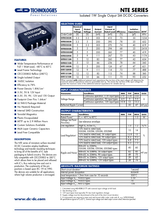
NTE SERIES
Isolated 1W Single Output SM DC-DC Converters
FEATURES s Wide Temperature Performance at
Full 1 Watt Load, –40°C to 85°C s Lead Frame Technology s CECC00802 Reflow (280°C) s Single Isolated Output s 1kVDC Isolation s Efficiency to 78% s Power Density 1.8W/cm3 s 3.3V, 5V & 12V Input s 3.3V, 5V, 9V, 12V and 15V Output s Footprint Over Pins 1.64cm 2 s UL 94V-0 Package Material s No Heatsink Required s Internal SMD Construction s Toroidal Magnetics s Plastic Encapsulated s MTTF up to 2.9 Million Hours s Custom Solutions Available s Multi Layer Ceramic Capacitors s Lead Free Compatible
RE-0505S;RE-0512S;RE-2405S;RE-0505SP;RE-1205S;中文规格书,Datasheet资料
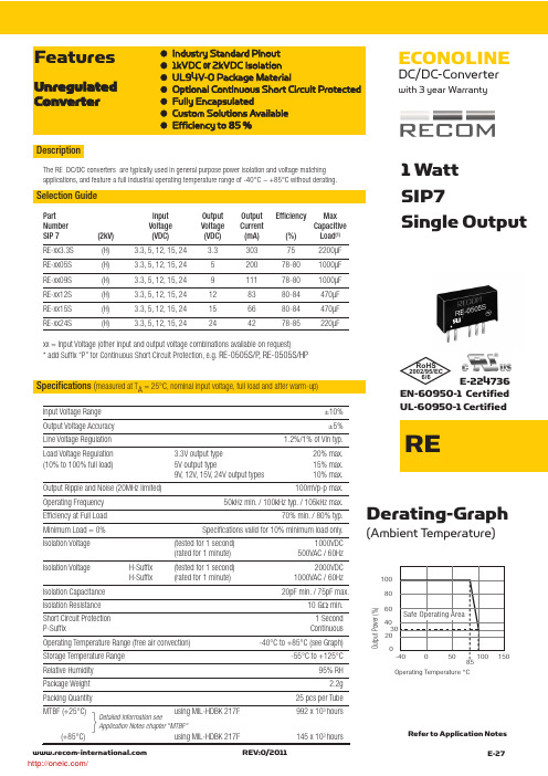
Selection GuideO u t p u t P o w e r (%)100602040Operating Temperature °C80Specifications (measured at T A = 25°C, nominal input voltage, full load and after warm-up)1 Watt SIP7Single OutputDerating-Graph(Ambient T emperature)●Industry Standard Pinout ●1kVDC or 2kVDC Isolation ●UL94V-0 Package Material●Optional Continuous Short Circuit Protected ●Fully Encapsulated●Custom Solutions Available ●Efficiency to 85%FeaturesUnregulated Converter}Detailed Information seeApplication Notes chapter "MTBF"DescriptionThe RE DC/DC converters are typically used in general purpose power isolation and voltage matching applications, and feature a full industrial operating temperature range of -40°C ~ +85°C without derating.Part Input Output Output Efficiency Max Number Voltage Voltage Current Capacitive SIP 7(2kV)(VDC)(VDC)(mA)(%)Load (1)RE-xx3.3S (H) 3.3, 5, 12, 15, 24 3.3303752200µF RE-xx05S (H) 3.3, 5, 12, 15, 24520078-801000µF RE-xx09S (H) 3.3, 5, 12, 15, 24911178-801000µF RE-xx12S (H) 3.3, 5, 12, 15, 24128380-84470µF RE-xx15S (H) 3.3, 5, 12, 15, 24156680-84470µF RE-xx24S(H)3.3, 5, 12, 15, 24244278-85220µFxx = Input Voltage (other input and output voltage combinations available on request)* add Suffix “P” for Continuous Short Circuit Protection, e.g. RE-0505S/P , RE-0505S/HPInput Voltage Range ±10%Output Voltage Accuracy ±5%Line Voltage Regulation 1.2%/1% of Vin typ.Load Voltage Regulation 3.3V output type 20% max.(10% to 100% full load)5V output type15% max.9V, 12V, 15V, 24V output types10% max.Output Ripple and Noise (20MHz limited)100mVp-p max.Operating Frequency 50kHz min. / 100kHz typ. / 105kHz max.Efficiency at Full Load 70% min. / 80% typ.Minimum Load = 0%Specifications valid for 10% minimum load only.Isolation Voltage (tested for 1 second)1000VDC (rated for 1 minute)500VAC / 60Hz Isolation Voltage H-Suffix (tested for 1 second)2000VDC H-Suffix(rated for 1 minute)1000VAC / 60Hz Isolation Capacitance 20pF min. / 75pF max.Isolation Resistance 10 G Ωmin.Short Circuit Protection 1 Second P-SuffixContinuousOperating Temperature Range (free air convection)-40°C to +85°C (see Graph)Storage Temperature Range -55°C to +125°CRelative Humidity 95% RH Package Weight2.2gPacking Quantity 25 pcs per Tube MTBF (+25°C)using MIL-HDBK 217F992 x 103 hours (+85°C)using MIL-HDBK 217F145 x 103 hoursEN-60950-1 Certified UL-60950-1 CertifiedREV:0/2011E-27 REECONOLINEDC/DC-Converterwith 3 year WarrantyRefer to Application NotesRoHS2002/95/EC6/6E-224736/E-28REV: 0/2011R E7 PIN SIP PackageXX.X ± 0.5 mm XX.XX ± 0.25 mmRE Pin Connections Pin #Single1 +Vin2 –Vin 4 –Vout 6+Vout Recommended Footprint DetailsPackage Style and Pinning (mm)3rd angle projectionTypical CharacteristicsRE SeriesECONOLINEDC/DC-ConverterE f f i c i e n c y %100040%0%100%40Efficiency / Load 60%80%20%206080Total Output current (%)Deviation / Load-10.00040%0%100%D e v i a t i o n f r o m N o m i n a l (%)60%80%20%-5.000Total Output current (%)0.0005.00010.00015.00020.00025.000E f f i c i e n c y %100040%0%100%40Efficiency / Load 60%80%20%206080Total Output current (%)E f fi c i e n c y %10040%0%100%40Efficiency / Load60%80%20%206080Total Output current (%)Deviation / Load-10.00040%0%100%D e v i a t i o n f r o m No m i n a l (%)60%80%20%-5.000Total Output current (%)0.0005.00010.00015.00020.00025.000Deviation / Load-10.00040%0%100%D e v i a t i o n f r o m N o m i n a l (%)60%80%20%-5.000Total Output current (%)0.0005.00010.00015.00020.00025.000RE-xx05SRE-xx12SRE-xx15SNotesNote 1Maximum capacitive load is defined as the capacitive load that will allow start up in under 1 second without damage to the converter.Certifications CB Test Report Report: US/15348/UL IEC 60950-1:2005 2nd Ed.UL General Safety Report: E224736UL 60950-1 1st Ed.EN General SafetyReport: IL-R7108EN60950-1:2001 + A11:2004/分销商库存信息:RECOM-POWERRE-0505S RE-0512S RE-2405SRE-0505S/P RE-1205S RE-0515SRE-2412S RE-1515S RE-0509SRE-0524S RE-053.3S RE-1209SRE-1215S RE-1224S RE-123.3SRE-0505S/H RE-0509S/H RE-0512S/H RE-0515S/H RE-0524S/H RE-053.3S/H RE-1205S/H RE-1209S/H RE-1212S/H RE-1215S/H RE-1224S/H RE-123.3S/H RE-1505S RE-1509S RE-1512SRE-1524S RE-153.3S RE-2409SRE-2424S RE-243.3S RE-3.305SRE-3.309S RE-3.312S RE-3.315SRE-3.324S RE-3.33.3S RE-0509S/P RE-0512S/P RE-0524S/P RE-053.3S/P RE-1205S/P RE-1209S/P RE-1212S/P RE-1215S/P RE-1224S/P RE-123.3S/P RE-1505S/H RE-1509S/H RE-1512S/H RE-1515S/H RE-1524S/H RE-153.3S/H RE-2405S/H RE-2409S/H RE-2412S/H RE-2415S/H RE-2424S/H RE-243.3S/H RE-3.305S/H RE-3.309S/H RE-3.312S/H RE-3.315S/H RE-3.324S/H RE-3.33.3S/H RE-1212S RE-1505S/P RE-1509S/P RE-1512S/P RE-1515S/P RE-1524S/P RE-153.3S/P RE-2405S/P RE-2409S/P RE-2412S/P RE-2415S/P RE-2424S/P RE-243.3S/P RE-3.305S/P RE-3.309S/P RE-3.312S/P RE-3.315S/P RE-3.324S/P RE-3.33.3S/P RE-0505S/HP RE-0509S/HP RE-0512S/HP RE-0515S/HP RE-0524S/HP RE-053.3S/HP RE-1205S/HP RE-1209S/HP RE-1212S/HP RE-1215S/HP RE-1224S/HP RE-123.3S/HP RE-2415S RE-0515S/P RE-1505S/HP RE-1509S/HP RE-1512S/HP RE-1515S/HP RE-1524S/HP RE-153.3S/HP RE-2405S/HP RE-2409S/HP RE-2412S/HP RE-2415S/HP RE-2424S/HP RE-243.3S/HP RE-3.305S/HP RE-3.309S/HP RE-3.312S/HP RE-3.315S/HP RE-3.324S/HP RE-3.33.3S/HP。
RECOM 电源调压器 R-5xxxA 系列数据手册说明书

FeaturesSwitching Regulator• Non-isolated• Synchronous rectification design • Adjustable output voltage• 2, 3, 4 & 5AMP adjustable positive step down integrated switching regulator • Over load protection• Continuous short circuit protection • Efficiency up to 96%R-5xxxPA_DADescriptionThe R-5xxxA series is a high performance 1.2V to 5.5V, 2Amp to 5Amp, 12-Pin SIP (single in-line package) integrated switching regulator (ISR). The synchronous - rectified design yields excellent efficiencies up to 96%. Short circuit protection reduces the short circuit input current to under 50mA. Autosense function compensates for any losses in long circuit loops.DC/DC Converter2,3,4,5 Amp SIP12Vertical &IEC/EN60950-1 certifiedR-542.5xA 4.5 - 18 2.5 1.6 - 5.5 4 91 89 88 300/6800R-543.3xA 4.5 - 18 3.3 1.6 - 5.5 4 93 92 91 300/6800R-545.0xA 6.5 - 18 5.0 3.0 - 5.5 4 95 94 93 300/6800R-551.2xA 4.4 - 18 1.2 1.0 - 3.0 5 81 80 78 300/6800R-551.8xA 4.5 - 18 1.8 1.1 - 4.5 5 86 85 84 300/6800R-552.5xA 4.5 - 18 2.5 1.6 - 5.5 5 90 89 88 300/6800R-553.3xA 4.5 - 18 3.3 1.6 - 5.5 5 92 91 90 300/6800R-555.0xA 7.0 - 1.8 5.0 3.0 - 5.5 5 94 93 92 300/6800Notes:Note1: Vin-Vout ≥ 1.5V~4.0V depending on Vout if adjust function is used Note2: please refer to basic characteristicsNotes:Note3: x can be …P“= vertical through hole x can be …D“ = bent for horizontal through hole mountingModel NumberingOrdering Examples:R-553.3PA Iout= 5A nom. Vout= 3.3VDC P= vertical through holeR-522.5DA Iout= 2Anom. Vout= 2.5VDC D= bent for horizontal through hole mountingPinning (3)Output Current (A)nom. Output VoltageR-5_ __ xASpecifications (refer to standard application circuit, Ta= 25°C)Specifications (refer to standard application circuit, Ta= 25°C)Specifications (refer to standard application circuit, Ta= 25°C)Trim Tables or Calculation2ADC R-521.2PA/DA R-521.8PA/DA R-522.5PA/DA R-523.3PA/DA R-525.0PA/DA 3ADC R-531.2PA/DA R-531.8PA/DA R-532.5PA/DA R-533.3PA/DA R-535.0PA/DA 4ADC R-541.2PA/DA R-541.8PA/DA R-542.5PA/DA R-543.3PA/DA R-545.0PA/DA 5ADC R-551.2PA/DA R-551.8PA/DA R-552.5PA/DA R-553.3PA/DA R-555.0PA/DAVout nom. 1.2VDC 1.8VDC 2.5VDC 3.3VDC 5.0VDC Vout adj.R1R2R1R2R1R2R1R2R1R21.337kΩ 3.7kΩ750Ω1.511.5kΩ10kΩ2.1KΩ390Ω1.68.2kΩ18kΩ 3.0KΩ750Ω1.7 6.5kΩ41kΩ 4.1KΩ 1.2kΩ1.8 5.2kΩ 5.6KΩ 1.7kΩ1.9 4.3kΩ36kΩ7.5KΩ2.2kΩ2.03.6kΩ 1.8kΩ10.5KΩ 2.8kΩ2.4 2.1kΩ 5.2kΩ82KΩ 6.8kΩ2.5 1.8kΩ 4.3kΩ8.5kΩ2.6 1.65kΩ3.6kΩ33kΩ10.5kΩ3.0 1.05kΩ 2.1kΩ 6.2kΩ33kΩ470Ω3.2 1.65kΩ4.1kΩ110kΩ 1.6kΩ3.3 1.5kΩ 3.4kΩ 2.2kΩ3.4 1.35kΩ 2.9kΩ36kΩ 3.0kΩ3.6 1.07kΩ 2.2kΩ11kΩ4.7kΩ3.9780Ω 1.4kΩ4.7kΩ8.5kΩ4.5390Ω650Ω 1.6Ω30kΩ4.9350Ω820Ω220kΩ5.0290Ω680Ω5.1220Ω560Ω28kΩ5.539Ω190Ω 2.6kΩSpecifications (refer to standard application circuit, Ta= 25°C)PROTECTIONSParameter Condition Value Short Circuit Protection (SCP)continuous, automatic recovery Short Circuit Input Current50mA max.continued on next pageSpecifications (refer to standard application circuit, Ta= 25°C)DIMENSION AND PHYSICAL CHARACTERISTICSParameterTypeValueMaterial case pottingnon-conducive black plastic, (UL94 V-0)epoxy, (UL94 V-0)Dimension (LxWxH)32.2 x 9.1 x 15.0mmWeight9g typ.continued on next pageENVIRONMENTALParameterConditionValueOperating Temperature Range *************************************/s-40°C to +85°CMaximum Case Temperature +110°C Thermal Impedance @ natural convection 0.1m/s25°C/W Operating Humidity non-condensing95% RH max.Operating Altitude 2000m Pollution Degree PD2MTBFaccording to MIL-HDBK 217F, G.B.+25°C +85°C749 x 103 hours 150 x 103 hoursSAFETY AND CERTIFICATIONSCertificate Type (Safety)Report / File NumberStandard Information Technology Equipment, General Requirements for Safety 1605077-12IEC60950-1:2005, 2nd Edition + AM2:2013EN60950-1:2006 + AM2:2013EAC RU-AT.49.09571TP TC 004/2011RoHS 2+RoHS-2011/65/EU + AM-2015/863Specifications (refer to standard application circuit, Ta= 25°C)PACKAGING INFORMATIONParameter Type ValuePackaging Dimensions (LxWxH)R-5xxxDAR-5xxxPA520.0 x 20.0 x 19.0mm530.0 x 23.0 x 19.0mmPackaging Quantity tube 15pcs Storage Temperature Range-40°C to +125°CThe product information and specifications may be subject to changes even without prior written notice.The product has been designed for various applications; its suitability lies in the responsibility of each customer. The products are not authorized for use in safety-critical applications without RECOM’s explicit written consent. A safety-critical application is an application where a failure may reasonably be expected to endanger or cause loss of life, inflict bodily harm or damage property. The applicant shall indemnify and hold harmless RECOM, its affiliated companies and its representatives against any damage claims in connection with the unauthorizeduse of RECOM products in such safety-critical applications.。
Z555中文资料

Document Number: 63007For any questions, contact: foil@Military and Space Established ReliabilityVishay Foil ResistorsBulk Metal ® Foil TechnologyRNC90Y and RNC90Z (Z-Foil) to MIL-PRF-55182/9INTRODUCTIONVishay Military Established Reliability resistors are available in resistance values from 4.99 Ω through 121 k Ω and for tolerances from ± 0.005 % to ± 1.0 %. The same resistors are also available as a non-qualified product for customers desiring higher or lower resistance values and the same or better performance capabilities. (See table 2) Both the qualified and the non-qualified version are manufactured on the same production line facilities and are subjected to the same process, lot control, conditioning, and GRP A (100 %)screening. Qualified versions receive additional MIL Group B and C testing.FEATURES•QPL product with established reliability (R): meets requirements of MIL-PRF-55182/9•Load life stability: ± 0.005 % for 2000 h, 0.3 W at + 125 °C •Temperature coefficient of resistance (TCR): ± 2 ppm/°C max.(- 55 °C to + 175 °C)•Resistance tolerance: to ± 0.005 %•Thermal EMF: < 0.1 µV/°C•Qualified resistance range: 4.99 Ω to 121 k Ω (RNC90Y)30.1 Ω to 121 k Ω (RNC90Z)•Specially conditioned non-QPL resistors available See data sheet “Improved Performance Tested”•Fast thermal stabilization•Rise time: 1 ns without ringing•Special coatings that provide a cushioning layer which isolates the resistive element from external stresses and moisture •Electrostatic discharge (ESD) above 25 000 V •Non inductive, non capacitive design •Current noise < - 42 dB•Prototype sample available from 72 hNotes1.Qualification and failure rate verification test data is maintained by Vishay Foil and is available upon request. Lot traceability and identification data is maintained by Vishay Foil for 7 years.2.Load life ΔR Maximum can be reduced by 80 % through Enhanced Reliability Testing (ERT). Consult Vishay Applications Engineering for details.3.Inductance (L) due mainly to the leads.4.Not to exceed power rating of resistor.5.µV/°C relates to EMF due to lead temperature differences and µV/W due to power applied to the resistor.6.0.200" (5.08 mm) lead spacing available - specify RNC90T for RNC90Y, and RNC90S for RNC90Z.TABLE 1 - SPECIFICATIONS COMPARISONSPECIFICATION RNC90Y (QUALIFIED) MIL-PRF-55182/9 CHARACTERISTIC Y LIMITS RNC90Z (QUALIFIED) MIL-PRF-55182/9 CHARACTERISTIC Z LIMITS S555 (NON-QUALIFIED)VISHAY PERFORMANCE LIMITS Z555 (NON-QUALIFIED)VISHAY PERFORMANCE LIMITSTemperature Coefficient of Resistance ± 5 ppm/°C ± 2 ppm/°C ± 5 ppm/°C± 3 ppm/°C ± 2.5 ppm/°C ± 2 ppm/°C(- 55 °C to + 125 °C)(- 55 °C to + 175 °C)(- 55 °C to + 125 °C)± 10 ppm/°C(- 55 °C to + 125 °C)(+ 125 °C to + 175 °C)Resistance Range 4.99 Ω to 121 k Ω30.1 Ω to 121 k Ω 1 Ω to 150 k Ω 4.99 Ω to 25 Ω> 25 Ω to 80 Ω> 80 ΩFailure RateLevel R Level R Not specified Not specifiedLoad-Life Stability 0.3 W at + 125 °C at 2000 h ± 0.05 % maximum ΔR ± 0.05 % maximum ΔR ± 0.015 % maximum ΔR 2)± 0.015 % maximum ΔR 2)at 10000 h ± 0.5 % maximum ΔR± 0.5 % maximum ΔR± 0.05 % maximum ΔR 2)± 0.05 % maximum ΔR 2)Current Noise Not specified Not specified - 40 dB minimum - 40 dB minimumHigh-Frequency Operation Rise TimeNot specified Not specified 1.0 ns at 1 k Ω 1.0 ns at 1 k ΩInductance 3) (L)Not specified Not specified 0.1 µH maximum 0.1 µH maximum 0.08 µH typical 0.08 µH typical Capacitance (C)Not specified Not specified 1.0 pF maximum 1.0 pF maximum 0.5 pF typical 0.5 pF typical Voltage Coefficient 0.0005 %/V 0.0005 %/V 0.0001 %/V 0.0001 %/V Working Voltage 4)300 V maximum 300 V maximum 300 V maximum 300 V maximum Thermal EMF 5)Not specifiedNot specified0.1 µV/°C maximum 0.1 µV/°C maximum 1 µV/W maximum 1 µV/W maximumMilitary and Space Established ReliabilityVishay Foil ResistorsBulk Metal ® Foil TechnologyRNC90Y and RNC90Z (Z-Foil) to MIL-PRF-55182/9 For any questions, contact: foil@Document Number: 63007Document Number: 63007For any questions, contact: foil@Military and Space Established ReliabilityBulk Metal ® Foil Technology RNC90Y and RNC90Z (Z-Foil) to MIL-PRF-55182/9Vishay Foil ResistorsNote•S555 and Z555 units are manufactured on the same production line facilities and are subjected to all the same process and lot control requirements imposed on RNC90Y (Z) version, as well as all of the special screening, environmental conditioning and documentation stipulations outlined in MIL-PRF 55182/9Note* For non-standard requests, please contact application engineering.TABLE 2 - MODEL SELECTIONMODELNUMBER RESISTANCE RANGE (Ω)STANDARD RESISTANCETOLERANCE FAILURE RATE AMBIENT POWER RATING AVERAGE WEIGHT(g)DIMENSIONS TIGHTEST %LOOSEST %at + 70 °C at + 125 ° C INCHES mmRNC90Y30.1 to 121K ± 0.005± 1.0M, P , R (SeeT able 3)0.6 W 0.3 W 0.6W: 0.105 ± 0.010L: 0.300 ± 0.010H: 0.326 ± 0.010ST: 0.015 ± 0.005SW: 0.040 ± 0.005LL: 1.000 ± 0.125LS: 0.150 ± 0.005 2.67 ± 0.257.62 ± 0.258.28 ± 0.250.38 ± 0.131.02 ± 0.1325.4 ± 3.183.81 ± 0.1316.2 to 30.0± 0.05± 1.04.99 to 16.0± 0.1± 1.0RNC90Z 30.1 to 121K ± 0.005± 1.00.6 W 0.3 W 0.6S555(NON QPL)30.1 to 121K ± 0.005± 1.0-0.6 W 0.3 W 0.620 to < 30.1± 0.01± 1.05 to < 20± 0.05± 1.02 to < 5± 0.1± 1.01 to < 2± 0.5± 1.0> 121K to 150K ± 0.005± 1.0-0.4 W 0.2 W 0.6Z555(NON QPL)30.1 to 121K ± 0.005± 1.0-0.6 W 0.3 W 0.620 to < 30.1± 0.01± 1.04.99 to < 20R ± 0.05± 1.0TABLE 3 - GLOBAL PART NUMBER INFORMATIONNEW GLOBAL PART NUMBER:Y1189100R500AR0L (preferred part number format)DENOTES PRECISIONVALUE LIFE FAILURE RATE (LFR)AER*YR = ΩK = k ΩR = ± 0.01 %P = ± 0.1 %M = ± 1.0 %0 = standard 1 - 999 = customPRODUCT CODE RESIST ANCE TOLERANCEPACKAGING 1189 = RNC90Z 0089 = RNC90Y 1508 = RNC90T 1506 = RNC90S 0088 = S5551288 = Z555V = ± 0.005 %T = ± 0.01 %A = ± 0.05 %B = ± 0.1 %D = ± 0.5 %F = ± 1.0 %L = bulk pack R = tape and reelFOR EXAMPLE: ABOVE GLOBAL ORDER Y1189 100R500 A R 0 L:TYPE: RNC90Z VALUE: 100.5 ΩABSOLUTE TOLERANCE: ± 0.05 %LIFE FAILURE RATE (LFR): ± 0.01 %AER: standardPACKAGING: bulk packHISTORICAL PART NUMBER:RNC90Z 100R50A R B (will continue to be used)RNC90Z 100R50A R B MODEL OHMIC VALUERESIST ANCE TOLERANCE LIFE FAILURE RA TE (LFR)P ACKAGING RNC90Z RNC90S RNC90Y RNC90T S555Z555100.5 ΩV = ± 0.005 %T = ± 0.01 %A = ± 0.05 %B = ± 0.1 %D = ± 0.5 %F = ± 1.0 %R = ± 0.01 %P = ± 0.1 %M = ± 1.0 %B = bulk pack18910R 50Y 1A R 000LMilitary and Space Established ReliabilityVishay Foil ResistorsBulk Metal ® Foil TechnologyRNC90Y and RNC90Z (Z-Foil) to MIL-PRF-55182/9 For any questions, contact: foil@Document Number: 63007The response of military and non military grade resistors to environmental stresses can be made better by “Improved Performance Testing” (IPT). The IPT part will see burn-in and cycling that removes the “knee” from the normal drift of non IPT parts. (See Table 4 for the improvement to expect in military parts when calling for Vishay recommended screening). Users should be aware that IPT testing renders the part non QPL and so a 3XXXXX part number will be assigned by Vishay. Consult Applications Engineering for details and ordering advice.CAGE #18612“Commercial and Government Entity”Formerly “FSCM”TABLE 4 - IMPROVED PERFORMANCE TESTING (NON-QPL APPROVED) VS. QPLTEST GROUPTESTRNC90YMIL-PRF-55182/9VISHAYIMPROVED PERFORMANCETESTING (IPT) LIMITS METHOD PARAGRAPHLIMITS IPower Conditioning not done -± 0.0025 %Thermal Shock and 4.8.2-± 0.0025 %Overload Combined 4.8.3± 0.05 %± 0.0025 %IIResistance TemperatureCharacteristic 4.8.9± 5 ppm/°C< ± 2 ppm/°C (- 55 °C to + 125 °C)(Can be sorted for tighter tracking)Low T emperature Storage 4.8.23± 0.05 %± 0.0025 %Low Temperature Operation4.8.10± 0.05 %± 0.0025 %T erminal Strength4.8.11± 0.02 %± 0.001 %IIIDWV4.8.12± 0.02 %± 0.001 %Insulation Resistance 4.8.13104 M Ω> 104 M ΩResistance to Soldering Heat4.8.14± 0.02 %± 0.001 %Moisture Resistance4.8.15± 0.05 %± 0.015 %IV Shock 4.8.16± 0.01 %± 0.0025 %Vibration4.8.17± 0.02 %± 0.0025 %V Load Life at + 125 °C; 2000 h 4.8.18± 0.05 %± 0.005 % (50 ppm)Load Life at + 125 °C; 10000 h4.8.18± 0.5 %± 0.015 % (150 ppm)V (a)+ 85 °C Power Rating --± 0.005 % (50 ppm)+ 70 °C Power Rating 4.8.18± 0.05 %± 0.005 % (50 ppm)V (b)+ 25 °C Power Rating--± 0.005 % (50 ppm)VI Storage Life--± 0.0025 %VII High T emperature Exposure 4.8.19± 0.5 %± 0.005 %VIIIMax. Allowance Reactance--< 1 %Current Noise --< - 42 dB Voltage Coefficient4.8.200.0005 %/V < 0.00001 %/V -(5 ppm/V)(< 0.1 ppm/V)Thermal EMF--0.1 µV/°CDisclaimer Legal Disclaimer NoticeVishayAll product specifications and data are subject to change without notice.Vishay Intertechnology, Inc., its affiliates, agents, and employees, and all persons acting on its or their behalf (collectively, “Vishay”), disclaim any and all liability for any errors, inaccuracies or incompleteness contained herein or in any other disclosure relating to any product.Vishay disclaims any and all liability arising out of the use or application of any product described herein or of any information provided herein to the maximum extent permitted by law. The product specifications do not expand or otherwise modify Vishay’s terms and conditions of purchase, including but not limited to the warranty expressed therein, which apply to these products.No license, express or implied, by estoppel or otherwise, to any intellectual property rights is granted by this document or by any conduct of Vishay.The products shown herein are not designed for use in medical, life-saving, or life-sustaining applications unless otherwise expressly indicated. Customers using or selling Vishay products not expressly indicated for use in such applications do so entirely at their own risk and agree to fully indemnify Vishay for any damages arising or resulting from such use or sale. Please contact authorized Vishay personnel to obtain written terms and conditions regarding products designed for such applications.Product names and markings noted herein may be trademarks of their respective owners.元器件交易网Document Number: 。
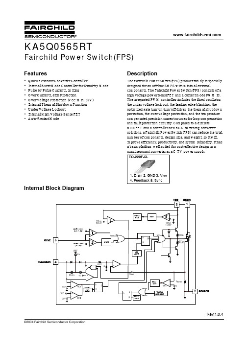
KA5Q0565RT中文资料
Min. Typ. Max. Unit
14 15 16 V 8 9 10 V
18 20 22 kHz
0 1 3%
0 ±5 ±10 %
92 95 98 %
-
-
0%
0.7 0.9 1.1 mA 6.9 7.5 8.1 V 4 5 6 µA
27 30 33 V 0.9 1.0 1.1 V 140 160 - °C
-
Typ. -
-
1.8 780 90 40 15 45 60 40
43
4.0 7.3
Max. -
200
300
2.2 40
100 130 90
55
-
Unit V µA µA Ω pF
nS
nC
3
元器件交易网
KA5Q0565RT
Electrical Characteristics (Continued)
Total Power Dissipation
Operating Junction Temperature Operating Ambient Temperature Storage Temperature Range Thermal Resistance ESD Capability, HBM Model (All pins) ESD Capability, Machine Model (All pins)
-
11V on
+
12V off
+
+
OSC
-
-
2.5R
R
+
7.5V VCC
30V
Idelay 1V
+
-
OLP
ECONOLINE DC DC 转换器说明书
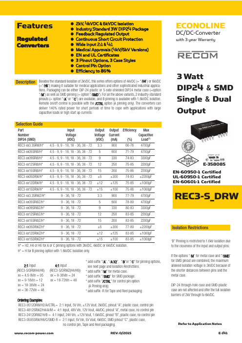
ECONOLINEDC/DC-Converterwith 3 year WarrantyREC3-S_DRW●2kV, 4kVDC &6kVDC Isolation●Industry Standard 3W DIP24 Package ●Feedback Regulated Output●Continuous Short Circuit Protection ●Wide Input 2:1 & 4:1●Medical Approvals (4kV/6kV Versions)●EN and UL Certificates●3 Pinout Options, 3 Case Styles ●Control Pin Option ●Efficiency to 86%FeaturesRegulated Converters3 WattDIP24 & SMD Single &DualOutputEN-60950-1 Certified UL-60950-1 Certified EN-60601-1 CertifiedSelection GuidePart Input Output Output Efficiency Max Number Voltage Voltage Current Capacitive DIP24 (SMD)(VDC)(VDC)(mA)(%)Load (1)REC3-xx3.3SRW/H* 4.5 - 9, 9 - 18, 18 - 36, 36 - 72 3.390066-764700µF REC3-xx05SRW/H* 4.5 - 9, 9 - 18, 18 - 36, 36 - 72560071-794700µF REC3-xx09SRW/H* 4.5 - 9, 9 - 18, 18 - 36, 36 - 72933074-833300µF REC3-xx12SRW/H* 4.5 - 9, 9 - 18, 18 - 36, 36 - 721225075-852200µF REC3-xx15SRW/H* 4.5 - 9, 9 - 18, 18 - 36, 36 - 721520075-862200µF REC3-xx05DRW/H* 4.5 - 9, 9 - 18, 18 - 36, 36 - 72±5±30074-83±2200µF REC3-xx12DRW/H* 4.5 - 9, 9 - 18, 18 - 36, 36 - 72±12±12575-85±1000µF REC3-xx15DRW/H* 4.5 - 9, 9 - 18, 18 - 36, 36 - 72±15±10075-86±1000µF REC3-xx3.3SRWZ/H*9 - 36, 18 - 72 3.390077-794700µF REC3-xx05SRWZ/H*9 - 36, 18 - 72560078-804700µF REC3-xx09SRWZ/H*9 - 36, 18 - 72933080-833300µF REC3-xx12SRWZ/H*9 - 36, 18 - 721225083-852200µF REC3-xx15SRWZ/H*9 - 36, 18 - 721520083-852200µF REC3-xx05DRWZ/H*9 - 36, 18 - 72±5±30077-80±2200µF REC3-xx12DRWZ/H*9 - 36, 18 - 72±12±12583-85±1000µF REC3-xx15DRWZ/H*9 - 36, 18 - 72±15±10083-85±1000µFH* = H2, H4 or H6 for A or C pinning options with 2kVDC, 4kVDC or 6kVDC isolation.H* = H for B pinning option with 1.6kVDC isolation only.Besides the standard isolation of 2kVDC, this series offers options of 4kVDC (= "/H4") or 6kVDC(="/H6") making it suitable for medical applications and other sophisticated industrial a pplica-tions. Packaging can be either DIP-24 plastic or 5-side-shielded DIP24 metal case (=option "/M ") as well as SMD pinning (= option "/SMD "). For all the above variants, 2 industry-standard pinouts (= option "/A "or "/C ") are available, and B pinning is available with 1.6kVDC isolation.Remote on/off control is possible with the /CTRL option (A pinning only). The converters can deliver 140% rated power for short periods of time to cope with applications with large capacitive loads or high start up currents.Description 2:1Input 4:1Input(REC3-S/DRWH4/H6) (REC3-S/DRWZ(H4/H6))xx = 4.5-9Vin = 05 xx = 9-36Vin = 24xx = 9-18Vin = 12 xx = 18-72Vin = 48 xx = 18-36Vin = 24xx = 36-72Vin = 48*add suffix "/A ", "/A /X2", "/B "or "/C " for pinning options,see next page and Isolation Restrictions.*add suffix "/M " for metal case.* add suffix "/SMD " for SMD package.* add suffix "/CTRL " for control pin option (A Pinning only)* add suffix -R for Tape and Reel packagingIsolation Restrictions‘B” Pinning is restricted to 1.6kV isolation dueto the closeness of the input and output pins.If the options "/M " for metal case and "/SMD "for SMD pinout are combined, the maximum allowed isolation voltage is 2kVDC because of the shorter distances between pins and the metal case.DIP-24 through-hole case and SMD-plastic case are not affected and offer the full isolation barriers of 2kV through to 6kVDC.Ordering Examples:REC3-0512DRW/H2/A/CTRL= 2:1 input, 5V Vin, ±12V Vout, 2kVDC, pinout “A”, plastic case, control pin REC3-4812SRWZ/H4/A/M = 4:1 input, 48V Vin, 12V Vout, 4kVDC, pinout “A”, metal case, no control pin REC3-2412DRWZ/H/B = 4:1 input, 24V Vin, ±12V Vout, 1.6kVDC, pinout “B”, plastic case, no control pin REC3-0505SRW/H6/C/SMD-R = 2:1 input, 5V Vin, 5V Vout, 6kVDC, SMD pinout “C”, plastic case,no control pin, Tape and Reel packaging.Refer to Application NotesE-358085RoHS2011/65/EU6/6Input Voltage Range 2:1 & 4:1Output Voltage Accuracy ±2% max.Line Regulation (HL-LL)±0.4% max.Load Regulation (for output load current change from 20% to 100%)±0.6% max.Minimum Load 10% (2)Output Ripple and Noise (0,1µF capacitor on output, 20MHz BW)50mVp-p max.Switching Frequency at Full Load 2:1 Input types 90kHz min. / 150kHz max.and nominal Input Voltage 4:1 Input types 120kHz min. / 180kHz max.Input Filter Pi Network Efficiency at Full Load see above No Load Power Consumption 300mW max.Isolation Voltage H2-Suffix (tested for 1 second)2000VDC(rated for 1 minute**)1000VAC / 60HzIsolation Voltage H4-Suffix (tested for 1 second)4000VDC(rated for 1 minute**)2000VAC / 60HzIsolation Voltage H6-Suffix (tested for 1 second)6000VDC(rated for 1 minute**)3000VAC / 60HzIsolation Capacitance 2:1 Input types 20pF min. / 60pF max.4:1 Input types 40pF min. / 80pF max.Isolation Resistance 1 G Ωmin.Short Circuit Protection (Max temp. = 60°C during short circuit conditions)Continuous, Auto Restart Operating Temperature Range 5V input types -40°C to +80°C (see Graph)(free air convection)others -40°C to +85°C (see Graph)Storage Temperature Range -55°C to +125°C Relative Humidity 95% RH Case Material Non-Conductive Plastic or Metal Thermal Impedance Natural convection 20°C/W for plastic case12°C/W for metal casePackage Weight 13g Packing Quantity 15 pcs per Tube100 pcs per ReelMTBF (+25°C)using MIL-HDBK 217F 1043 x 103 hours (+85°C)using MIL-HDBK 217F 186 x 103 hours Certifications UL General Safety Report: E358085UL 60950-1 1st Ed.C22.2 No. 60950-1-03EN General Safety Report: SPCLVD1212007EN60950-1:2006 + A1:2010+A12:2011EN Medical Safety Report: MDD1205098-3 + RM1205098-3 IEC/EN 60601-1 3rd Ed.Medical Report + ISO14971 Risk AssessmentDerating-Graph(Ambient T emperature)Specifications (measured at T A = 25°C, nominal input voltage, full load and after warm-up)O u t p u t P o w e r (%)1201002060125750-40Operating Temperature (°C)0805025804010010550Safe Operating AreaTypical CharacteristicsE f f i c i e n c y %100040%0%100%40Efficiency / Load 60%80%20%206080Total Output current (%)E f f i c i e n c y%100040%0%100%40Efficiency / Load 60%80%20%206080Total Output current (%)E f f i c i e n c y %10040%0%100%40Efficiency / Load60%80%20%206080Total Output current (%)Dual 2:1 InputSingle 2:1 InputSingle 2:1 Input Vin = 5VO u t p u t P o w e r (%)1201002060125750-40Operating Temperature (°C)0805025854010010550Safe Operating Area}Detailed Information seeApplication Notes chapter "MTBF"R E C 3-R WNotes Note 1:Maximum capacitive load is defined as the capacitive load that will allow start up in under 1 second without damage to the converter Note 2:The REC3-RW series requires a minimum of 10% load on the output to maintain specified regulation. Operating under no-load conditions will not damage these devices; however, they may not meet all listed specifications.**Any data referred to in this datasheet are of indicative nature and based on our practical experience only. For further details, please refer to our Application Notes.REC3-RW“C” Pinning /H2, /H4 & /H6E f f i c i e n c y %100040%0%100%40Efficiency / Load 60%80%20%206080Total Output current (%)E f f i c i e n c y %100040%0%100%40Efficiency / Load 60%80%20%206080Total Output current (%)E f f i c i e n c y %100040%0%100%40Efficiency / Load 60%80%20%206080Total Output current (%)Dual 4:1 InputSingle 4:1 InputSingle 4:1 Input Typical Characteristics - ContinuedPackage Style and Pinning (mm) DIP 24 , Wide Input 2:1 & 4:1“A” Pinning /H2, /H4 & /H6Pin Connections Pin #Single Single/X2Dual 1 (option)CTRL CTRL CTRL 2–Vin –Vin –Vin 3–Vin –Vin –Vin 9NC No Pin Com 11NC NC –Vout 14+Vout +Vout+Vout 16–Vout –Vout Com 22+Vin +Vin +Vin 23+Vin+Vin+VinNC = No Connection CTRL OptionVin+0V22,232,31CTRL TTL Input1k W RECx-xxxx/CTRL1N4148OnOffON = Open or 0V< V ctrl <1.2V OFF = 2.2V< V ctrl<12VCTRL OptionRecommended Footprint Details1Bottom View121110213152324Pin Connections Pin #Single Dual 1+Vin +Vin 2+Vin +Vin 10NC Com 11NC Com 12–Vout NC 13+Vout –Vout 15NC +Vout 23–Vin –Vin 24–Vin–VinNC = No ConnectionXX.X ± 0.5 mm XX.XX ± 0.25 mmRecommended Footprint DetailsXX.X ± 0.5 mm XX.XX ± 0.25 mm1Bottom View12111032131415222324Recommended Footprint DetailsXX.X ± 0.5 mm XX.XX ± 0.25 mmPackage Style and Pinning (mm) DIP 24 , Wide Input 2:1 & 4:1SMD PinningRecommended Footprint DetailsSMD pin connections follow standard package A (/A/SMD), B (/B/SMD) or C (/C/SMD) pinning.All unused pins are NC(No Connection). See Below for detailed pinout listsPin Connections Pin #Single Dual 1 (Option) CTRLCTRL 2–Vin –Vin 3–Vin –Vin 4NC NC 5NC NC 9NC Com 10NC NC 11NC -Vout 12NCNCPin Connections Pin #Single Dual 13 NC NC 14+Vout +Vout 15NC NC 16-Vout Com 20NC NC 21NC NC 22+Vin +Vin 23+Vin +Vin 24NCNCPin Connections Pin #Single Dual 1 +Vin +Vin 2NC –Vout 3NC Com 4NC NC 5NC NC 9NC NC 10-Vout Com 11+Vout +Vout 12-Vin-VinPin Connections Pin #Single Dual 13 -Vin -Vin 14+Vout +Vout 15-Vout Com 16NC NC 20NC NC 21NC NC 22NC Com 23NC -Vout 24+Vin+VinPin Connections Pin #Single Dual 1 +Vin +Vin 2+Vin +Vin 3NC NC 4NC NC 5NC NC 9NC NC 10NC Com 11NC Com 12-VoutNCPin Connections Pin #Single Dual 13 +Vout -Vout 14NC NC 15NC +Vout 16NC NC 20NC NC 21NC NC 22NC NC 23-Vin -Vin 24-Vin-Vin/A/SMD Pinning/B/SMD Pinning/C/SMD PinningPin Connections Pin #Single Dual 1+Vin +Vin 2No Pin –Vout 3No Pin Com 10–Vout Com 11+Vout +Vout 12–Vin –Vin 13–Vin –Vin 14+Vout +Vout 15–Vout Com 22No Pin Com 23No Pin –Vout 24+Vin+VinNC = No Connection for all packages incl.SMD case the length of plastic case is 31,8 mm, length of metal case 32.0 mm“B” Pinning /H (1.6kV Only)R E C 3-R WThe product information and specifications are subject to change without prior notice. RECOM products are not authorized for use in safety-critical applications (such as life support) without RECOM’s explicitwritten consent. A safety-critical application is defined as an application where a failure of a RECOM product may reasonably be expected to endanger or cause loss of life, inflict bodily harm or damage property. The buyer shall indemnify and hold harmless RECOM, its affiliated companies and its representatives against any damage claims in connection with the unauthorized use of RECOM products in such safety-critical applications.。
5R55N-_5R55S-_5R55W

011H 5R55N (Plastic) (0.4” Pickup Tube)........................................................................... 1 99-Up 46011 011H 5R55S (Metal/Plastic) (1.3” Pickup Tube) (Car)......................................................... 1 03-Up 46011B 011H 5R55S/W (Metal/Plastic) (2.4” Pickup Tube) (SUV).................................................... 1 02-Up 46011A
H
46
195
FORD 5R55N, 5R55S, 5R55W
46300W
46010
46010A 46010B
5R55N (99-Up)
Lincoln LS Jaguar X200
5R55W/S (02-Up)
Explorer
ill.
DESCRIPTION
QTY. YEAR
PART NO.
DELUXE KITS (SUPER KITS)
5R55N
5R55N
FORD 5R55N, 5R55S, 5R55W
F
G
Deluxe Kit---------------------------------- 008 Compliance Kit------------------------- 007 Master Kit -------------------------------- 006 Less Steel Kit--------------------------- 004 Overhaul Kit ----------------------------- 002 Bushing Kit ------------------------------- 030 Washer Kit -------------------------------- 200 Bearing Kit ------------------------------- 201 Technical Manual ------------------ 400 Pump Part---------------------------------- 507 Valve Body Parts -------------------- 741 Case Parts ------------------------------- 761 Note: Not all items are available for all transmissions
人民电器 RDM5Z系列剩余电流保护断路器 选型手册说明书
完善的产业链和个性化解决方案,满足全球客户的不同需求!人民电器集团是人民控股集团全资公司,中国500强企业之一,始创于1986年。
人民电器集团以工业电器为核心产业,拥有浙江、上海、南昌、抚州、枣庄、合肥六大制造基地、35家全资子公司150家控股成员企业、1500多家加工协作企业和5000多家销售公司。
产品畅销全球125个国家和地区,广泛应用于浦东机场、京沪高铁、三峡水电、北京地铁、奥运场馆南水北调、青藏铁路、嫦娥探月工程、越南太安水电枢纽等国内外重大工程项目,位居世界机械企业500强前列。
2023年,经世界品牌实验室测评,品牌价值788.15亿。
公司简介COMPANY PROFILE更 安 全保障人员生命及财产安全。
更 可 靠不间断供应电力,全天随时可用。
更 高 效降低能源消耗和成本,提高生产率,缩短需求供应时间。
优化机械、工厂流程,提高使用舒适性。
更 经 济更 环 保通过可再生能源提供能量,减少二氧化碳排放量。
电力与能源电力石油石化交通工业与机器矿业/建材水利/水处理汽车数据中心IT高科技互联网商业网络银行保险金融机构电信运营楼宇办公楼宇工业建筑基础设施住宅住宅建设公共建设小区设施剩余电流保护断路器逆变器直流断路器直流塑壳断路器直流框架断路器光伏箱变直流熔断器直流浪涌保护器终端新能源RDM5L系列剩余电流保护断路器G-092RDM5系列塑料外壳式断路器G-044RDB5-125系列小型断路器G-163RDM5Z系列剩余电流保护断路器G-120RDQH5系列双电源自动转换开关G-142RDB5-80S系列预付费小型断路器G-162RDB5系列小型断路器G-151RDB5-63系列小型断路器G-160RDW5系列万能式断路器G -001RDM5E系列电子式断路器G-065RDXQ5系列双电源自动转换开关G-138RDB5-80系列小型断路器G-161RDB5-40系列小型断路器G-159RDQ5系列双电源自动转换开关G-147RDHM5系列剩余电流保护断路器G-103RDB5-125S系列小型断路器G-164RDB5LE-40系列剩余电流动作断路器G-172RDB5LE-63Y系列一体式剩余电流动作断路器G-184RDB5GS系列隔离开关G-170RDB5LE-100系列剩余电流动作断路器G-178RDB5LE-63MA系列剩余电流动作断路器G-174RDB5-125H系列小型断路器G-167RDB5LE-63系列剩余电流动作断路器G-173RDB5GQ系列自恢复式过欠压保护器G-186RDB5LE-32系列剩余电流动作断路器G-171RDB5LE-125H系列剩余电流动作断路器G-181RDB5LEs-63系列剩余电流动作断路器G-176RDQH5Y系列双电源自动转换开关G-147G-191RDU5Z系列电涌保护器RDR5系列热过载继电器G-197RDJ5系列电磁继电器G-203RDC5系列交流接触器G-192RDCJ5系列接触式继电器G-201RDS5系列电动机保护断路器G-205RDU5系列电涌保护器G-189RDSCB系列电涌保护器G-188正常工作条件和环境适应性□ □ 海拔高度:2000m□ 电磁干扰:适用于电磁环境A □ 使用类别:B类□ 污染等级:污染等级为3级□ 安装级别:断路器主电路、欠电压脱扣器线圈、智能控制器的电源变压器初级线圈 为IV ,控制电路、辅助电路为III□ 防护等级:IP20 (当断路器安装在柜体室内,且加装门框后,防护等级能达到IP40)□ 储存条件:-25~+55℃□ 运输条件:应轻拿轻放,不应倒置,避免剧烈碰撞环境温度:周围空气温度为-5~+40℃,24h 的平均值不超过+35℃产品概述RDW5系列万能式断路器适用于交流50/60HZ ,额定工作电压AC400V/690V ,额定电流至6300A 以下的配电网络中,主要用作配电、馈电和发电保护,使线路及电源设备免受过载、欠电压、过电压、电流电压不平衡、短接和接地/漏电等故障的危害。
FSQ0565RSLDTU;中文规格书,Datasheet资料
!AN-4141: Troubleshooting and Design Tips for Fairchild Power Switch (FPS™) Flyback Applications !AN-4145: Electromagnetic Compatibility for Power Converters!AN-4147: Design Guidelines for RCD Snubber of Flyback Converters DescriptionA Quasi-Resonant Converter (QRC) generally shows lower EMI and higher power conversion efficiency than a conventional hard-switched converter with a fixed switching frequency. The FSQ-series is an integrated Pulse-Width Modulation (PWM) controller and SenseFET specifically designed for quasi-resonant operation and Alternating Valley Switching (AVS). The PWM controller includes an integrated fixed-frequency oscillator, Under-Voltage Lockout (UVLO), Leading-Edge Blanking (LEB), optimized gate driver, internal soft-start, temperature-compensated precise current sources for a loop compensation, and self-protection circuitry. Compared with a discrete MOSFET and PWM controller solution, the FSQ-series can reduce total cost, component count, size, and weight; while simultaneously increasing efficiency, productivity, and system reliability. This device provides a basic platform for cost-effective designs of quasi-resonant switching flyback converters.FSQ0565RS/RQ — Green-Mode Farichild Power Switch (FPS™) for Quasi-Resonant Operation Green-Mode Fairchild Power Switch (FPS™) for Quasi-Resonant Operation - Low EMI and High Efficiency Features!Optimized for Quasi-Resonant Converters (QRC)!Low EMI through Variable Frequency Control and AVS (Alternating Valley Switching)!High-Efficiency through Minimum Voltage Switching!Narrow Frequency Variation Range over Wide Load and Input Voltage Variation!Advanced Burst-Mode Operation for Low Standby Power Consumption!Simple Scheme for Sync Voltage Detection!Pulse-by-Pulse Current Limit !Various Protection Functions: Overload Protection (OLP), Over-Voltage Protection (OVP), Internal Thermal Shutdown (TSD) with Hysteresis, Output Short Protection (OSP) !Under-Voltage Lockout (UVLO) with Hysteresis!Internal Startup Circuit !Internal High-Voltage Sense FET (650V)!Built-in Soft-Start (17.5ms)Applications!Power Supply for LCD TV and Monitor, VCR, SVR, STB, and DVD & DVD Recorder!Adapter Related Resources Visit: /apnotes/ for:!AN-4134: Design Guidelines for Offline Forward Converters Using Fairchild Power Switch (FPS™)!AN-4137: Design Guidelines for Offline Flyback Converters Using Fairchild Power Switch (FPS™)!AN-4140: Transformer Design Consideration for Offline Flyback Converters Using Fairchild Power Switch (FPS™)Figure 1. Typical Flyback ApplicationV SDV OCP SQQR GNDAOCP(1.1V)TSD2V OSPLPFLPFBurst-Mode Voltages T J = 25°C, t PD = 200ns(10)V BURL0.250.350.45V Hysteresis200mVContinued on the following page...FSQ0565RS/RQ — Green-Mode Farichild Power Switch (FPS™) for Quasi-Resonant Operation Comparison Between FSDM0x65RNB and FSQ-Series Differences Between FSQ0565RS and FSQ0565RQ Function FSDM0x65RE FSQ-Series FSQ-Series Advantages Operation Method Constant Frequency PWM Quasi-Resonant Operation!Improved efficiency by valley switching!Reduced EMI noise!Reduced components to detect valley point EMI Reduction Frequency Modulation Reduced EMI Noise !Valley Switching!Inherent Frequency Modulation!Alternate Valley Switching Hybrid Control CCM or AVS Based on Load and Input Condition!Improves efficiency by introducing hybrid control Burst-Mode Operation Burst-Mode Operation Advanced Burst-Mode Operation!Improved standby power by advanced burst-mode Strong Protections OLP, OVP OLP, OVP, OSP!Improved reliability through precise OSP TSD145°C without Hysteresis140°C with 60°C Hysteresis!Stable and reliable TSD operation!Converter temperature range Function FSQ0565RS FSQ0565RQ Remark I LIM 2.25A 3.0A!Lower current peak is suitable to reduce conduc-tion loss!Higher current peak is suitable for handling higher power Over Voltage Protection V CC OVP(triggered by V CC voltage)Sync OVP(triggered by Sync voltage)!Sync OVP is suitable when V CC voltage is pre reg-ulated.FSQ0565RS/RQ — Green-Mode Farichild Power Switch (FPS™) for Quasi-Resonant OperationFigure 5. Operating Supply Current (I OP ) vs. T AFigure 6. UVLO Start Threshold Voltage(V START ) vs. T AFigure 7. UVLO Stop Threshold Voltage(V STOP ) vs. T AFigure 8. Startup Charging Current (I CH ) vs. T A-252550751001250.00.20.40.60.8N o r m Temperature [°C]-2502550751001250.00.20.40.60.8N o r m Temperature [°C]-252550751001250.00.20.40.60.81.01.2N o r m a l i z e dTemperature [°C]-252550751001250.00.20.40.60.81.01.2N o r m a l i z e dTemperature [°C]0.20.40.60.81.01.2N o r m a l i z e d0.20.40.60.81.01.2N o r m a l i z e dFSQ0565RS/RQ — Green-Mode Farichild Power Switch (FPS™) for Quasi-Resonant OperationFigure 11. Blanking Time (t B ) vs. T AFigure 12. Feedback Source Current (I FB ) vs. T AFigure 13. Shutdown Delay Current (I DELAY ) vs. T AFigure 14. Burst-Mode High Threshold Voltage(V burh ) vs. T A-252550751001250.00.20.40.60.8N o r m Temperature [°C]-2502550751001250.00.20.40.60.8N o r m a Temperature [°C]-252550751001250.00.20.40.60.81.01.2N o r m a l i z e dTemperature [°C]-252550751001250.00.20.40.60.81.01.2N o r m a l i z e dTemperature [°C]0.00.20.40.60.81.01.2N o r m a l i z e d0.00.20.40.60.81.01.2N o r m a l i z e d分销商库存信息: FAIRCHILDFSQ0565RSLDTU。
RSO-0505S;RSO-0505D;RSO-2412DZ;RSO-2405SZH3;RSO-243.3S;中文规格书,Datasheet资料

ECONOLINEDC/DC-Converterwith 3 year WarrantyRSO E-95REV:1/2011EN-60950-1 Certified EN-60601-1 CertifiedDescriptionHigh-power-density, an industrial temperature range of -40°C to +85°C and extra features like On-Off-control are just some of the characteristics of this converter, ideal for highly sophisticated industrial-designs. The RSO series is available with isolation of 2kV or 3kV by chosing option "/H2"or "/H3" in which case it is also ideal for medical applications which additionally require EN-60601-1 certification. The standard version offers 2:1 input voltage range, while the “Z” version features 4:1input voltage range, which includes an input voltage range covering both 5V and 12V supplies.1 WattSIP8 Isolated Single &Dual Output●2:1 and 4:1 Wide Input Voltage Ranges ●1kVDC, 2kVD or 3kVDC Isolation ●UL94V-0 Package Material●Certified for Medical Applications ●Continuous Short Circuit Protection ●Low Noise●No External Capacitor needed ●Efficiency to 83%FeaturesRegulated ConvertersSelection GuidePart NumberInput Rated Output Output Current Efficiency Max Voltage Range Voltage typ.CapacitiveSIP8(VDC)(VDC)(mA)(%)Load (1)RSO-xx3.3S* 4.5-9**, 9-18 3.330068-723300µF18-36, 36-7270RSO-xx05S* 4.5-9**, 9-18520073-751200µF18-36, 36-7275-78RSO-xx09S* 4.5-9**, 9-18911174-78680µF18-36, 36-7278-81RSO-xx12S* 4.5-9**, 9-18128375-80680µF18-36, 36-7280-83RSO-xx15S* 4.5-9**, 9-18156775-80680µF18-36, 36-7280-83RSO-xx3.3D* 4.5-9**, 9-18±3.3±15068-72±1500µF18-36, 36-7270RSO-xx05D* 4.5-9**, 9-18±5±10073-75±470µF18-36, 36-7275-76RSO-xx09D* 4.5-9**, 9-18±9±5674-78±470µF18-36, 36-7278RSO-xx12D* 4.5-9**, 9-18±12±4275-79±330µF18-36, 36-7279-80RSO-xx15D* 4.5-9**, 9-18±15±3475-79±330µF18-36, 36-7279-80RSO-xx3.3SZ*9-36 3.330068-703300µF18-7270RSO-xx05SZ* 4.5-18**, 9-36520073-781200µF18-7275RSO-xx09SZ* 4.5-18**, 9-36911175-81680µF18-7278RSO-xx12SZ* 4.5-18**, 9-36128377-83680µF18-7280RSO-xx15SZ* 4.5-18**, 9-36156778-83680µF18-7280RSO-xx3.3DZ*9-36±3.3±15070-74±1500µF18-7270RSO-xx05DZ* 4.5-18**, 9-36±5±10073-77±470µF18-7275RSO-xx09DZ* 4.5-18**, 9-36±9±5674-78±470µF18-7278RSO-xx12DZ* 4.5-18**, 9-36±12±4275-80±330µF18-7280RSO-xx15DZ* 4.5-18**, 9-36±15±3475-80±330µF18-7280No suffix is standard isolation (1kVDC) e.g, RSO-0505S*add suffix /H2 or /H3 for 2kVDC or 3kVDC isolation, e.g, RSO-0505S/H2, RSO-0505DZ/H3** derate to 75% if Vin<5V, 12V 4:1 input also requires an external 10µF input capacitor.Refer to Application NotesRoHS2002/95/EC6/6O u t p u t P o w e r (%)100602040Operating Temperature °C80Derating-Graph(Ambient T emperature)2:1Input 4:1Input (RS0-S/D) (RSO-SZ/DZ)xx = 4.5-9Vin = 05 xx = 4.5-18Vin = 12xx = 9-18Vin = 12 xx = 9-36Vin = 24 xx = 18-36Vin = 24 xx = 18-72Vin = 48xx = 36-72Vin = 48/E-96REV: 1/2011R S 0Input Voltage Range 2:1 and 4:1Output Voltage Accuracy ±2% typ.Line Voltage Regulation 2:1±0.2% max.4:1±0.5% max.Load Voltage Regulation 2:1±0.4% max.(10% to 100% full load)4:1±0.5% typ.Minimum Load0%Output Ripple and Noise (20MHz limited)50mVp-p max.Operating Frequency 2:1200kHz min. / 500kHz max.4:1100kHz min. / 800kHz max.Efficiency at Full Load See Selection GuideQuiescent Current RSO-05xxS_D, SZ_DZ 40mA typ.Nominal input Voltage RSO-12xxS_D32mA typ.(Standard, /H2 and /H3)RSO-24xxS_D, SZ_DZ 25mA typ.RSO-48xxS_D, SZ_DZ15mA typ.CTRL Pin drive current /see Notes)3mA typ, 6mA max.Quiescent Input Current when Converter is OFF 10mA max.Isolation Voltage Standard (tested for 1 second)1000VDC(rated for 1 minute)500VAC / 60Hz/H2 Version (tested for 1 second)2000VDC(rated for 1 minute)1000VAC / 60Hz/H3 Version (tested for 1 second)3000VDC(rated for 1 minute)1500VAC / 60HzIsolation Capacitance Standard 2:1 Single 10pF min. / 40pF typ. / 60pF max.Isolation Capacitance /H2 and /H32:1 Single 5pF min. / 30pF typ. / 60pF max.Isolation Capacitance Standard 2:1 Dual 120pF min. / 170pF typ. / 250pF max.Isolation Capacitance /H2 and /H32:1 Dual 5pF min. / 30pF typ. / 60pF max.Isolation Capacitance Standard 4:1 Single/Dual 200pF max.Isolation Capacitance /H2 and /H34:1 Single/Dual 30pF max.Isolation Resistance >1G Ωmin.Short Circuit ProtectionContinuousOperating Temperature Range (free air convection)-40°C to +85°C (see Graph)Storage Temperature Range -55°C to +125°CRelative Humidity 95% RH Package Weight 4.7gPacking Quantity 22 pcs per TubeMTBF (+25°C)using MIL-HDBK 217F 1685 x 103 hours (+85°C)using MIL-HDBK 217F254 x 103 hoursSpecifications (Core Operating Area)measured at T A = 25°C, nominal input voltage, full load and after warm-up time unless otherwise specifiedTypical ApplicationE f f i c i e n c y %100040%0%100%40Efficiency / Load 60%80%20%206080Total Output current (%)RSO-24xxS}Detailed Information seeApplication Notes chapter "MTBF"-Vin-Vout+Vout+VinE f f i c i e n c y %100040%0%100%40Efficiency / Load 60%80%20%206080Total Output current (%)RSO-1205SZ/RSO E-97REV:1/20113rd angleprojection8 PIN SIP PackageXX.X ± 0.5 mm XX.XX ± 0.25 mmPin 8 (NC*)This pin is used internally and must have no external connection.Pin 5 (NC)Not connected internally.Pin 3 (CTRL)This pin provides an Off function which puts the converter into a low power mode. When the pin is ‘high’ the converter is OFF and when the pin is high ‘Z’ the converter is ON. There is no allowed low state for this pin.Package Style and Pinning (mm)Single Output Recommended Footprint DetailsPin Connections Pin #SingleDual1 –Vin –Vin2 +Vin +Vin 3CTRL CTRL 5NC NC 6+Vout +Vout7 –Vout C om8NC*–VoutNC = No ConnectionNC* = NC, but no external Connection allowed.CTRL Examples+VoutCtrlTTL Remote CTRL CircuitVoltage to be applied via a limiting resistor with a recom-mended value of 1K for RSO-05xx; 3.3K for RSO-12xx;4.7K for RSO-24xx and 10K for RSO-48xx.Control Pin Input Current: 10mA Voltage Set Point Accuracy with external input/outputcapacitors refer to typ. ± 1%recommended test circuit: max. ±2%Control Pin (CTRL) Input Current, control voltage applied via 1K resistor,output voltage must typ. 3mA reduce to 0V: max. 6mA+VoutIsolated Remote CTRL CircuitNotes Note 1Maximum capacitive load is defined as the capacitive load that will allow start up in under 1 second without damage to the converterCertifications EN General Safety Report: IL-R7109EN60950-1:2001 + A11:2004EN Medical SafetyReport: PS071001601EN60601-1:1990 + A11:1996/分销商库存信息:RECOM-POWERRSO-0505S RSO-0505D RSO-2412DZ RSO-2405SZ/H3RSO-243.3S RSO-1212S RSO-2412D RSO-2415D RSO-0505S/H2 RSO-2405SZ/H2RSO-2405DZ RSO-0505S/H3 RSO-2412SZ/H3RSO-1205DZ RSO-1212DZ RSO-2415DZ/H3RSO-2412DZ/H3RSO-4812SZ/H3 RSO-4805SZ/H3RSO-4812DZ/H3RSO-4815DZ/H3 RSO-2409S RSO-1209S RSO-1215S RSO-123.3S RSO-2415S RSO-2412S RSO-2405S RSO-0509S RSO-0512S RSO-053.3S RSO-2409SZ RSO-2412SZ RSO-2415SZ RSO-243.3SZ RSO-4805S RSO-4809S RSO-4812S RSO-4815S RSO-483.3S RSO-1205S RSO-0509D RSO-0509S/H2RSO-0512D RSO-0512S/H2 RSO-0515D RSO-0515S/H2RSO-053.3D RSO-053.3S/H2RSO-2409DZ RSO-2409SZ/H2 RSO-2412SZ/H2RSO-2415DZ RSO-2415SZ/H2 RSO-243.3DZ RSO-243.3SZ/H2RSO-1205S/H3 RSO-1209S/H3RSO-1212S/H3RSO-1215S/H3 RSO-123.3S/H3RSO-2405S/H2RSO-2409S/H2 RSO-2412S/H2RSO-2415S/H2RSO-243.3S/H2 RSO-2405D RSO-2409D RSO-243.3D RSO-2405D/H2RSO-2409D/H2RSO-2412D/H2 RSO-2415D/H2RSO-243.3D/H2RSO-1205S/H2 RSO-1209S/H2RSO-1212S/H2RSO-1215S/H2 RSO-123.3S/H2RSO-1205D RSO-1209D RSO-1212D RSO-1215D RSO-123.3D RSO-0515S RSO-2405SZ RSO-1209SZ RSO-1215SZ RSO-123.3SZ RSO-0509S/H3 RSO-0512S/H3RSO-0515S/H3RSO-053.3S/H3 RSO-1205D/H2RSO-1209D/H2RSO-1212D/H2 RSO-1215D/H2RSO-123.3D/H2RSO-2409SZ/H3 RSO-2415SZ/H3RSO-243.3SZ/H3RSO-1205SZ/H2 RSO-1209DZ RSO-1209SZ/H2RSO-1212SZ/H2 RSO-1215DZ RSO-1215SZ/H2RSO-123.3DZ RSO-123.3SZ/H2RSO-4805SZ RSO-4809SZ RSO-4812SZ RSO-4815SZ RSO-483.3SZ RSO-2409S/H3RSO-2412S/H3RSO-2415S/H3 RSO-243.3S/H3RSO-2405D/H3RSO-2409D/H3 RSO-2412D/H3RSO-2415D/H3RSO-243.3D/H3 RSO-4805D RSO-4805S/H2RSO-4809D RSO-4809S/H2RSO-4812D RSO-4812S/H2 RSO-4815D RSO-4815S/H2RSO-483.3D。
CC3-0505SF-E中文资料

DC to DC ConvertersInsulated Type, Ultra Compact Size, 1.5 to 25W Output, 5-year Warranty PeriodCC-E SeriesFEATURES•Compact size(almost half floor space of existing product).•No tantalum capacitor and no aluminum electrolytic capacitor are used.•All series are equipped with a built-in remote control function (except for SIP).•Output voltage tolerance ±3%(under 10W, at single output).•Light weight(no potting).•It is a product conforming to RoHS directive.•These are PWB halogen-free pc board.•Both mountings of DIP type and SMD type are available.•UL60950-1, C-UL CSA 60950-1 and EN60950-1 approved (partial approved).PART NUMBERS AND RATINGS∗1An "x" within the product name is to be replaced by the symbol representing the terminal structure (F: DIP / R: SMD / S: SIP). Note that the SIP type is limited to 3W.∗2The output voltage can be set to 15V , ±15V , by connecting the 12Vout, ±12V TRM (output variable) to –Vout.∗324V single output is possible by opening the ±12Vout COM terminal and connecting the load to +Vout, –Vout. Also, 30V single output is possible when connecting the TRM terminal with –Vout under the same conditions.PRODUCT IDENTIFICATIONSConformity to RoHS Directive Output power Input voltage Output voltage3.3V 5V 12V(15V ∗2)±12V(15V ∗2) or 24V , 30V ∗31.5W5V CC1R5-0503Sx ∗1-E CC1R5-0505Sx-E CC1R5-0512Sx-E CC1R5-0512Dx-E 12V CC1R5-1203Sx-E CC1R5-1205Sx-E CC1R5-1212Sx-E CC1R5-1212Dx-E 24V CC1R5-2403Sx-E CC1R5-2405Sx-E CC1R5-2412Sx-E CC1R5-2412Dx-E 48V CC1R5-4803Sx-E CC1R5-4805Sx-E CC1R5-4812Sx-E CC1R5-4812Dx-E 3W5V CC3-0503Sx-E CC3-0505Sx-E CC3-0512Sx-E CC3-0512Dx-E 12V CC3-1203Sx-E CC3-1205Sx-E CC3-1212Sx-E CC3-1212Dx-E 24V CC3-2403Sx-E CC3-2405Sx-E CC3-2412Sx-E CC3-2412Dx-E 48V CC3-4803Sx-E CC3-4805Sx-E CC3-4812Sx-E CC3-4812Dx-E 6W5V CC6-0503Sx-E CC6-0505Sx-E CC6-0512Sx-E CC6-0512Dx-E 12V CC6-1203Sx-E CC6-1205Sx-E CC6-1212Sx-E CC6-1212Dx-E 24V CC6-2403Sx-E CC6-2405Sx-E CC6-2412Sx-E CC6-2412Dx-E 48V CC6-4803Sx-E CC6-4805Sx-E CC6-4812Sx-E CC6-4812Dx-E 10W 5V CC10-0503Sx-E CC10-0505Sx-E CC10-0512Sx-E CC10-0512Dx-E 12V CC10-1203Sx-E CC10-1205Sx-E CC10-1212Sx-E CC10-1212Dx-E 24V CC10-2403Sx-E CC10-2405Sx-E CC10-2412Sx-E CC10-2412Dx-E 48V CC10-4803Sx-E CC10-4805Sx-E CC10-4812Sx-ECC10-4812Dx-E15W 24V CC15-2403Sx-E CC15-2405Sx-E 25W24VCC25-2403Sx-E CC25-2405Sx-E•Conformity to RoHS Directive: This means that, in conformity with EU Directive 2002/95/EC, lead, cadmium, mercury, hexavalent chromium, and specific bromine-based flame retardants, PBB and PBDE, have not been used, except for exempted applications.ELECTRICAL CHARACTERISTICS∗1An "x" within the product name is to be replaced by the symbol representing the terminal structure (F: DIP / R: SMD). ∗2T otal output voltage is including input, load, and temperature regulation.∗3When the condition is 2-output, it is the balance load (balance load means the condition when the load current of +output and –output is equal).∗4Measurement bandwidth: 50MHz∗5T ypical input voltage, maximum output current.∗62-output products may be used as 24 to 30V single output with COM. terminal open.∗7TRM and –Vout are shorted.•T rim range: 3.3Vout is 3.15 to 3.6V , 5Vout is 4.75 to 6V , 12Vout is 11.4 to 15V , ±12Vout is ±11.4 to ±15V (22.8 to 30V).OUTPUT POWER - AMBIENT TEMPERATURE(DERATING)COMMON SPECIFICATIONSPart No.Input voltage (V)Output voltage ∗2(V)Output current (mA)Voltage stabilityOutput ripple noise voltage ∗4(mVp-p)typ./max.Efficiency ∗5(%) Input-output insulationInput (mV)max.Load ∗3(mV)max.T emperature (mV)1R5-0503Sx ∗1-E 4.5 to 9 3.3±3%0 to 40020408040/12071 Withstand voltage AC.500V 1minResistance DC.500V 50M Ωmin.CC1R5-0505Sx-E 4.5 to 95±3%0 to 30020408040/12077CC1R5-0512Sx-E 4.5 to 912±3%0 to 1254010020030/120804.5 to 915±3%∗70 to 1004010020030/12080CC1R5-0512Dx-E ∗6 4.5 to 9±12±5%±0 to 608060030030/120794.5 to 9±15±5%±0 to 508060030030/12079CC1R5-1203Sx-E 9 to 18 3.3±3%0 to 40020408040/12073CC1R5-1205Sx-E 9 to 185±3%0 to 30020408040/12078CC1R5-1212Sx-E 9 to 1812±3%0 to 1254010020030/120829 to 1815±3%0 to 1004010020030/12082CC1R5-1212Dx-E ∗69 to 18±12±5%±0 to 608060030030/120819 to 18±15±5%∗7±0 to 508060030030/12081CC1R5-2403Sx-E 18 to 36 3.3±3%0 to 40020408040/12072CC1R5-2405Sx-E 18 to 365±3%0 to 30020408040/12077CC1R5-2412Sx-E 18 to 3612±3%0 to 1254010020030/1208118 to 3615±3%0 to 1004010020030/12081CC1R5-2412Dx-E ∗618 to 36±12±5%±0 to 608060030030/1207918 to 36±15±5%∗7±0 to 508060030030/12079CC1R5-4803Sx-E 36 to 76 3.3±3%0 to 40020408040/12070CC1R5-4805Sx-E 36 to 765±3%0 to 30020408040/12076CC1R5-4812Sx-E 36 to 7612±3%0 to 1254010020030/1208036 to 7615±3%∗70 to 1004010020030/12080CC1R5-4812Dx-E ∗636 to 76±12±5%±0 to 608060030030/1207936 to 76±15±5%∗7±0 to 508060030030/12079Overcurrent protectionOutput current limitation system, auto recovery typeOperating temperature range–40 to +85°C[Derating is necessary whenoperating environment temperature exceed 50°C]Storage temperature range–40 to +85°CHumidity range 95(%)RH max.[Maximum wet-bulb temperature: 38°C]Vibration 10 to 55Hz, all amplitude 1.52mm, sweep time 15min[3 directions of X, Y , Z, each 2h]Amplitude980m/s 2(100G) 6ms[6 directions, each 3 times]Withstand voltage Eac Input to output, input to case, output to case: 500V , 1minInsulation resistance Input to output, input to case, output to case: 50M Ω min.[DC.500V]Safety standards UL60950-1, C-UL(CSA22.2 No.60950-1), EN60950-1 certified Weight3.2gSHAPES AND DIMENSIONS CC1R5-xxxxxF-E (DIP TYPE)RECOMMENDED PWB HOLE SIZE, LOCATION [TOP VIEW]CC1R5-xxxxxR-E (SMD TYPE)RECOMMENDED PWB HOLE SIZE, LOCATION [TOP VIEW]CONNECTIONS CC1R5-xxxxSx-ECC1R5-xxxxDx-EDimensions in mm Tolerance: ±0.5Dimensions in mm Tolerance: ±0.5TERMINAL PIN CONFIGUTATIONNo.1+Vin No.2RC No.3–Vin No.4NC No.5–Vout No.6TRM No.7+VoutTERMINAL PIN CONFIGUTATIONNo.1+Vin No.2RC No.3–Vin No.4–VoutNo.5Common out No.6TRM No.7+VoutCC3 T ype(DIP , SMD Types)ELECTRICAL CHARACTERISTICS∗1An "x" within the product name is to be replaced by the symbol representing the terminal structure (F: DIP / R: SMD). ∗2T otal output voltage is including input, load, and temperature regulation.∗3When the condition is 2-output, it is the balance load (balance load means the condition when the load current of +output and –output is equal).∗4Measurement bandwidth: 50MHz∗5T ypical input voltage, maximum output current.∗62-output products may be used as 24 to 30V single output with COM. terminal open.∗7TRM and –Vout are shorted.•T rim range: 3.3Vout is 3.15 to 3.6V , 5Vout is 4.75 to 6V , 12Vout is 11.4 to 15V , ±12Vout is ±11.4 to ±15V .OUTPUT POWER - AMBIENT TEMPERATURE(DERATING)COMMON SPECIFICATIONSPart No.Input voltage (V)Output voltage ∗2(V)Output current (mA)Voltage stabilityOutput ripple noise voltage ∗4(mVp-p)typ./max.Efficiency ∗5(%) Input-output insulationInput (mV)max.Load ∗3(mV)max.T emperature (mV)3-0503Sx ∗1-E 4.5 to 9 3.3±3%0 to 80020408040/12073Withstand voltage AC.500V 1minResistance DC.500V 50M Ωmin.CC3-0505Sx-E 4.5 to 95±3%0 to 60020408040/12077CC3-0512Sx-E 4.5 to 912±3%0 to 2504010020030/120824.5 to 915±3%∗70 to 2004010020030/12082CC3-0512Dx-E ∗6 4.5 to 9±12±5%±0 to 1258060030030/120814.5 to 9±15±5%±0 to 1008060030030/12081CC3-1203Sx-E 9 to 18 3.3±3%0 to 80020408040/12074CC3-1205Sx-E 9 to 185±3%0 to 60020408040/12079CC3-1212Sx-E 9 to 1812±3%0 to 2504010020030/120829 to 1815±3%0 to 2004010020030/12082CC3-1212Dx-E ∗69 to 18±12±5%±0 to 1258060030030/120819 to 18±15±5%∗7±0 to 1008060030030/12081CC3-2403Sx-E 18 to 36 3.3±3%0 to 80020408040/12073CC3-2405Sx-E 18 to 365±3%0 to 60020408040/12078CC3-2412Sx-E 18 to 3612±3%0 to 2504010020030/1208218 to 3615±3%0 to 2004010020030/12082CC3-2412Dx-E ∗618 to 36±12±5%±0 to 1258060030030/1208118 to 36±15±5%∗7±0 to 1008060030030/12081CC3-4803Sx-E 36 to 76 3.3±3%0 to 80020408040/12073CC3-4805Sx-E 36 to 765±3%0 to 60020408040/12079CC3-4812Sx-E 36 to 7612±3%0 to 2504010020030/1208136 to 7615±3%∗70 to 2004010020030/12081CC3-4812Dx-E ∗636 to 76±12±5%±0 to 1258060030030/1208036 to 76±15±5%∗7±0 to 1008060030030/12080Overcurrent protectionOutput current limitation system, auto recovery typeOperating temperature range–40 to +85°C[Derating is necessary whenoperating environment temperature exceed 50°C]Storage temperature range–40 to +85°CHumidity range 95(%)RH max.[Maximum wet-bulb temperature: 38°C]Amplitude 10 to 55Hz, all amplitude 1.52mm, sweep time 15min[3 directions of X, Y , Z, each 2h]Vibration980m/s 2(100G) 6ms[6 directions, each 3 times]Withstand voltage Eac Input to output, input to case, output to case: 500V , 1minInsulation resistance Input to output, input to case, output to case: 50M Ω min.[DC.500V]Safety standards UL60950-1, C-UL(CSA22.2 No.60950-1), EN60950-1 certified Weight4.5gCC3 T ype(SI P T ype)ELECTRICAL CHARACTERISTICS∗1T otal output voltage is including input, load, and temperature regulation.∗2When the condition is 2-output, it is the balance load (balance load means the condition when the load current of +output and –output is equal).∗3Measurement bandwidth: 50MHz∗4T ypical input voltage, maximum output current.∗52-output products may be used as 24 to 30V single output with COM. terminal open.∗6TRM and –Vout are shorted.•T rim range: 3.3Vout is 3.15 to 3.67V , 5Vout is 4.75 to 6V , 12Vout is 11.4 to 15V , ±12Vout is ±11.4 to ±15V .OUTPUT POWER - AMBIENT TEMPERATURE(DERATING)COMMON SPECIFICATIONSPart No.Input voltage (V)Output voltage ∗1(V)Output current (mA)Voltage stabilityOutput ripple noise voltage ∗3(mVp-p)typ./max.Efficiency ∗4(%) Input-output insulationInput (mV)max.Load ∗2(mV)max.T emperature (mV)3-0503SS-E 4.5 to 9 3.3±3%0 to 80020408040/12073Withstand voltage AC.500V 1minResistance DC.500V 50M Ωmin.CC3-0505SS-E 4.5 to 95±3%0 to 60020408040/12077CC3-0512SS-E 4.5 to 912±3%0 to 2504010020030/120824.5 to 915±3%∗60 to 2004010020030/12082CC3-0512DS-E ∗5 4.5 to 9±12±5%±0 to 1258060030030/120814.5 to 9±15±5%±0 to 1008060030030/12081CC3-1203SS-E 9 to 18 3.3±3%0 to 80020408040/12073CC3-1205SS-E 9 to 185±3%0 to 60020408040/12079CC3-1212SS-E 9 to 1812±3%0 to 2504010020030/120829 to 1815±3%0 to 2004010020030/12082CC3-1212DS-E ∗59 to 18±12±5%±0 to 1258060030030/120829 to 18±15±5%∗6±0 to 1008060030030/12082CC3-2403SS-E 18 to 36 3.3±3%0 to 80020408040/12073CC3-2405SS-E 18 to 365±3%0 to 60020408040/12078CC3-2412SS-E 18 to 3612±3%0 to 2504010020030/1208218 to 3615±3%0 to 2004010020030/12082CC3-2412DS-E ∗518 to 36±12±5%±0 to 1258060030030/1208118 to 36±15±5%∗6±0 to 1008060030030/12081CC3-4803SS-E 36 to 76 3.3±3%0 to 80020408040/12073CC3-4805SS-E 36 to 765±3%0 to 60020408040/12079CC3-4812SS-E 36 to 7612±3%0 to 2504010020030/1208236 to 7615±3%∗60 to 2004010020030/12082CC3-4812DS-E ∗536 to 76±12±5%±0 to 1258060030030/1208236 to 76±15±5%∗6±0 to 1008060030030/12082Overcurrent protectionOutput current limitation system, auto recovery typeOperating temperature range–40 to +85°C[Derating is necessary whenoperating environment temperature exceed 50°C]Storage temperature range–40 to +85°CHumidity range 95(%)RH max.[Maximum wet-bulb temperature: 38°C]Amplitude 10 to 55Hz, all amplitude 1.52mm, sweep time 15min[3 directions of X, Y , Z, each 2h]Vibration980m/s 2(100G) 6ms[6 directions, each 3 times]Withstand voltage Eac Input to output, input to case, output to case: 500V , 1minInsulation resistance Input to output, input to case, output to case: 50M Ω min.[DC.500V]Safety standards UL60950-1, C-UL(CSA22.2 No.60950-1), EN60950-1 certified is applying partially.Weight7.0gCC3 T ype(DIP , SMD Types)SHAPES AND DIMENSIONS CC3-xxxxxF-E (DIP TYPE)RECOMMENDED PWB HOLE SIZE, LOCATIONCC3-xxxxxR-E (SMD TYPE)RECOMMENDED PWB HOLE SIZE, LOCATION [TOP VIEW]CONNECTIONS CC3-xxxxSx-ECC3-xxxxDx-EDimensions in mm Tolerance: ±0.5TERMINAL PIN CONFIGUTATIONNo.1+Vin No.2RC No.3–Vin No.4NC No.5–Vout No.6TRM No.7+VoutTERMINAL PIN CONFIGUTATIONNo.1+Vin No.2RC No.3–Vin No.4–VoutNo.5Common out No.6TRM No.7+VoutCC3 T ype(SI P T ype)SHAPES AND DIMENSIONS CC3-xxxxxS-E (SIP TYPE)CONNECTIONS CC3-xxxxSS-ECC3-xxxxDS-EThe output voltage can be set to 15V , ±15V , by connecting the output variable terminal TRM of the 12Vout, ±12V output model to –Vout.24V single output is possible by opening the ±12Vout COM terminal andconnecting the load to +Vout, –Vout. Also, 30V single output is possible when connecting the TRM terminal with –Vout under the same conditions.TERMINAL PIN CONFIGUTATIONNo.1+Vout No.2NC No.3NC No.4–Vout No.5TRM No.6NC No.7–Vin No.8–Vin No.9+Vin No.10+VinTERMINAL PIN CONFIGUTATIONNo.1+Vout No.2COM No.3COM No.4–Vout No.5TRM No.6NC No.7–Vin No.8–Vin No.9+Vin No.10+VinELECTRICAL CHARACTERISTICS∗1An "x" within the product name is to be replaced by the symbol representing the terminal structure (F: DIP / R: SMD). ∗2T otal output voltage is including input, load, and temperature regulation.∗3When the condition is 2-output, it is the balance load (balance load means the condition when the load current of +output and –output is equal).∗4Measurement bandwidth: 50MHz∗5T ypical input voltage, maximum output current∗62-output products may be used as 24 to 30V single output with COM. terminal open.∗7TRM and –Vout are shorted.•T rim range: 3.3Vout is 3.15 to 3.6V , 5Vout is 4.75 to 6V , 12Vout is 11.4 to 15V , ±12Vout is ±11.4 to ±15V .OUTPUT POWER - AMBIENT TEMPERATURE(DERATING)COMMON SPECIFICATIONSPart No.Input voltage (V)Output voltage ∗2(V)Output current (mA)Voltage stabilityOutput ripple noise voltage ∗4(mVp-p)typ./max.Efficiency ∗5(%) Input-output insulationInput (mV)max.Load ∗3(mV)max.T emperature (mV)6-0503Sx ∗1-E 4.5 to 9 3.3±3%0 to 120020408040/12076Withstand voltage AC.500V 1minResistance DC.500V 50M Ωmin.CC6-0505Sx-E 4.5 to 95±3%0 to 100020408040/12079CC6-0512Sx-E 4.5 to 912±3%0 to 5004010020030/120824.5 to 915±3%∗70 to 4004010020030/12082CC6-0512Dx-E ∗6 4.5 to 9±12±5%±0 to 2508060030030/120824.5 to 9±15±5%±0 to 2008060030030/12082CC6-1203Sx-E 9 to 18 3.3±3%0 to 120020408040/12078CC6-1205Sx-E 9 to 185±3%0 to 120020408040/12082CC6-1212Sx-E 9 to 1812±3%0 to 5004010020030/120859 to 1815±3%0 to 4004010020030/12085CC6-1212Dx-E ∗69 to 18±12±5%±0 to 2508060030030/120859 to 18±15±5%∗7±0 to 2008060030030/12085CC6-2403Sx-E 18 to 36 3.3±3%0 to 120020408040/12077CC6-2405Sx-E 18 to 365±3%0 to 120020408040/12081CC6-2412Sx-E 18 to 3612±3%0 to 5004010020030/1208718 to 3615±3%0 to 4004010020030/12087CC6-2412Dx-E ∗618 to 36±12±5%±0 to 2508060030030/1208618 to 36±15±5%∗7±0 to 2008060030030/12086CC6-4803Sx-E 36 to 76 3.3±3%0 to 120020408040/12077CC6-4805Sx-E 36 to 765±3%0 to 120020408040/12081CC6-4812Sx-E 36 to 7612±3%0 to 5004010020030/1208636 to 7615±3%∗70 to 4004010020030/12086CC6-4812Dx-E ∗636 to 76±12±5%±0 to 2508060030030/1208636 to 76±15±5%∗7±0 to 2008060030030/12086Overcurrent protectionOutput current limitation system, auto recovery typeOperating temperature range–40 to +85°C[Derating is necessary whenoperating environment temperature exceed 50°C]Storage temperature range–40 to +85°CHumidity range 95(%)RH max.[Maximum wet-bulb temperature: 38°C]Amplitude 10 to 55Hz, all amplitude 1.52mm, sweep time 15min[3 directions of X, Y , Z, each 2h]Vibration980m/s 2(100G) 6ms[6 directions, each 3 times]Withstand voltage Eac Input to output, input to case, output to case: 500V , 1minInsulation resistance Input to output, input to case, output to case: 50M Ω min.[DC.500V]Safety standards UL60950-1, C-UL(CSA22.2 No.60950-1), EN60950-1 certified Weight5.8gSHAPES AND DIMENSIONS CC6-xxxxxF-E (DIP TYPE)RECOMMENDED PWB HOLE SIZE, LOCATIONCC6-xxxxxR-E (SMD TYPE)RECOMMENDED PWB HOLE SIZE, LOCATION [TOP VIEW]CONNECTIONS CC6-xxxxSx-ECC6-xxxxDx-EDimensions in mm Tolerance: ±0.5TERMINAL PIN CONFIGUTATIONNo.1+Vin No.2RC No.3–Vin No.4NC No.5–Vout No.6TRM No.7+VoutTERMINAL PIN CONFIGUTATIONNo.1+Vin No.2RC No.3–Vin No.4–VoutNo.5Common out No.6TRM No.7+VoutELECTRICAL CHARACTERISTICS∗1An "x" within the product name is to be replaced by the symbol representing the terminal structure (F: DIP / R: SMD). ∗2T otal output voltage is including input, load, and temperature regulation.∗3When the condition is 2-output, it is the balance load (balance load means the condition when the load current of +output and –output is equal).∗4Measurement bandwidth: 50MHz∗5T ypical input voltage, maximum output current∗62-output products may be used as 24 to 30V single output with COM. terminal open.∗7TRM and –Vout are shorted.•T rim range: 3.3Vout is 3.15 to 3.6V , 5Vout is 4.75 to 6V , 12Vout is 11.4 to 15V , ±12Vout is ±11.4 to ±15V .OUTPUT POWER - AMBIENT TEMPERATURE(DERATING)COMMON SPECIFICATIONSPart No.Input voltage (V)Output voltage ∗2(V)Output current (mA)Voltage stabilityOutput ripple noise voltage ∗4(mVp-p)typ./max.Efficiency ∗5(%) Input-output insulationInput (mV)max.Load ∗3(mV)max.T emperature (mV)10-0503Sx ∗1-E 4.5 to 9 3.3±3%0 to 250020408040/12084Withstand voltage AC.500V 1minResistance DC.500V 50M Ωmin.CC10-0505Sx-E 4.5 to 95±3%0 to 200020408040/12084CC10-0512Sx-E 4.5 to 912±3%0 to 8004010020030/120844.5 to 915±3%∗70 to 6404010020030/12084CC10-0512Dx-E ∗6 4.5 to 9±12±5%±0 to 4008060030030/120834.5 to 9±15±5%±0 to 3208060030030/12083CC10-1203Sx-E 9 to 18 3.3±3%0 to 250020408040/12084CC10-1205Sx-E 9 to 185±3%0 to 200020408040/12086CC10-1212Sx-E 9 to 1812±3%0 to 10004010020030/120889 to 1815±3%0 to 8004010020030/12088CC10-1212Dx-E ∗69 to 18±12±5%±0 to 4508060030030/120869 to 18±15±5%∗7±0 to 3608060030030/12086CC10-2403Sx-E 18 to 36 3.3±3%0 to 250020408040/12084CC10-2405Sx-E 18 to 365±3%0 to 200020408040/12086CC10-2412Sx-E 18 to 3612±3%0 to 10004010020030/1208718 to 3615±3%0 to 8004010020030/12087CC10-2412Dx-E ∗618 to 36±12±5%±0 to 4508060030030/1208618 to 36±15±5%∗7±0 to 3608060030030/12086CC10-4803Sx-E 36 to 76 3.3±3%0 to 250020408040/12084CC10-4805Sx-E 36 to 765±3%0 to 200020408040/12086CC10-4812Sx-E 36 to 7612±3%0 to 10004010020030/1208836 to 7615±3%∗70 to 8004010020030/12088CC10-4812Dx-E ∗636 to 76±12±5%±0 to 4508060030030/1208636 to 76±15±5%∗7±0 to 3608060030030/12086Overcurrent protectionOutput current limitation system, auto recovery typeOperating temperature range–40 to +85°C[Derating is necessary whenoperating environment temperature exceed 50°C]Storage temperature range–40 to +85°CHumidity range 95(%)RH max.[Maximum wet-bulb temperature: 38°C]Amplitude 10 to 55Hz, all amplitude 1.52mm, sweep time 15min[3 directions of X, Y , Z, each 2h]Vibration980m/s 2(100G) 6ms[6 directions, each 3 times]Withstand voltage Eac Input to output, input to case, output to case: 500V , 1minInsulation resistance Input to output, input to case, output to case: 50M Ω min.[DC.500V]Safety standards UL60950-1, C-UL(CSA22.2 No.60950-1), EN60950-1 certified Weight10.0gSHAPES AND DIMENSIONS CC10-xxxxxF-E (DIP TYPE)RECOMMENDED PWB HOLE SIZE, LOCATION [TOP VIEW]CC10-xxxxxR-E (SMD TYPE)RECOMMENDED PWB HOLE SIZE, LOCATION [TOP VIEW]CONNECTIONS CC10-xxxxSx-ECC10-xxxxDx-EDimensions in mm Tolerance: ±0.5Dimensions in mm Tolerance: ±0.5TERMINAL PIN CONFIGUTATIONNo.1+Vin No.2RC No.3–Vin No.4NC No.5–Vout No.6TRM No.7+VoutTERMINAL PIN CONFIGUTATIONNo.1+Vin No.2RC No.3–Vin No.4–VoutNo.5Common out No.6TRM No.7+VoutELECTRICAL CHARACTERISTICS∗1An "x" within the product name is to be replaced by the symbol representing the terminal structure (F: DIP / R: SMD). ∗2T otal output voltage is including input, load, and temperature regulation.∗3Measurement bandwidth: 50MHz∗4T ypical input voltage, maximum output currentOUTPUT POWER - AMBIENT TEMPERATURE(DERATING)COMMON SPECIFICATIONSPart No.Input voltage (V)Output voltage ∗2(V)Output current (mA)Voltage stabilityOutput ripple noisevoltage ∗3(mVp-p)typ./max.Efficiency ∗4(%) Input-output insulation Input (mV)max.Load (mV)max.T emperature (mV)max.CC15-2403Sx ∗1-E 18 to 36 3.3/–3 to +5%0 to 4500401208040/12089Withstand voltage AC.500V 1minResistance DC.500V 50M Ωmin.CC15-2405Sx-E18 to 36 5.0/–3 to +5%0 to 3000502008040/12089Overcurrent protectionOutput current limitation system, Output voltage shut-down typeOperating temperature range–40 to +85°C[Derating is necessary whenoperating environment temperature exceed 50°C]Storage temperature range–40 to +85°CHumidity range 95(%)RH max.[Maximum wet-bulb temperature: 38°C]Amplitude 10 to 55Hz, all amplitude 1.52mm, sweep time 15min[3 directions of X, Y , Z, each 2h]Vibration980m/s (100G) 6ms[6 directions, each 3 times]Withstand voltage Eac Input to output, input to case, output to case: 500V , 1minInsulation resistance Input to output, input to case, output to case: 50M Ω min[DC.500V]Safety standards UL60950-1, C-UL(CSA22.2 No.60950-1), EN60950-1 certified Weight12.5gSHAPES AND DIMENSIONS CC15-xxxxSF-E (DIP TYPE)RECOMMENDED PWB HOLE SIZE, LOCATION [TOP VIEW]CC15-xxxxSR-E (SMD TYPE)RECOMMENDED PWB HOLE SIZE, LOCATION [TOP VIEW]CONNECTIONDimensions in mm Tolerance: ±0.5Dimensions in mm Tolerance: ±0.5TERMINAL PIN CONFIGUTATIONNo.1NC No.10NC No.2NC No.11NC No.3RC No.12+Vout No.4NC No.13+Vout No.5NC No.14+Vout No.6+Vin No.15–Vout No.7+Vin No.16–Vout No.8–Vin No.17NCNo.9–VinELECTRICAL CHARACTERISTICS∗1An "x" within the product name is to be replaced by the symbol representing the terminal structure (F: DIP / R: SMD). ∗2T otal output voltage is including input, load, and temperature regulation.∗3Measurement bandwidth: 50MHz∗4T ypical input voltage, maximum output currentOUTPUT POWER - AMBIENT TEMPERATURE(DERATING)COMMON SPECIFICATIONSPart No.Input voltage (V)Output voltage ∗2(V)Output current (mA)Voltage stabilityOutput ripple noisevoltage ∗3(mVp-p)typ./max.Efficiency ∗4(%) Input-output insulation Input (mV)max.Load (mV)max.T emperature (mV)max.CC25-2403Sx ∗1-E 18 to 36 3.3/–3 to +5%0 to 7500401208040/12090Withstand voltage AC.500V 1minResistance DC.500V 50M Ωmin.CC25-2405Sx-E18 to 36 5.0/–3 to +5%0 to 5000502008040/12090Overcurrent protectionOutput current limitation system, Output voltage shut-down typeOperating temperature range–40 to +85°C[Derating is necessary whenoperating environment temperature exceed 50°C]Storage temperature range–40 to +85°CHumidity range 95(%)RH max.[Maximum wet-bulb temperature: 38°C]Amplitude 10 to 55Hz, all amplitude 1.52mm, sweep time 15min[3 directions of X, Y , Z, each 2h]Vibration500m/s (51G) 6ms[6 directions, each 3 times]Withstand voltage Eac Input to output, input to case, output to case: 500V , 1minInsulation resistance Input to output, input to case, output to case: 50M Ω min.[DC.500V]Safety standards UL60950-1, C-UL(CSA22.2 No.60950-1), EN60950-1 certified Weight20.0gSHAPES AND DIMENSIONS CC25-xxxxSF-E (DIP TYPE)RECOMMENDED PWB HOLE SIZE, LOCATION [TOP VIEW]CC25-xxxxSR-E (SMD TYPE)RECOMMENDED PWB HOLE SIZE, LOCATION [TOP VIEW]CONNECTIONDimensions in mm Tolerance: ±0.5Dimensions in mm Tolerance: ±0.5TERMINAL PIN CONFIGUTATIONNo.1NC No.10+Vin No.19–Vout No.2NC No.11+Vin No.20–Vout No.3NC No.12+Vin No.21–Vout No.4RC No.13NC No.22–Vout No.5NC No.14NC No.23–Vout No.6NC No.15+Vout No.24–Vout No.7–Vin No.16+Vout No.25NCNo.8–Vin No.17+Vout No.9–Vin No.18+VoutREMOTE CONTROL TERMINAL(RC)(DIP/SMD MODELS)1.5 to 10W TypesIt is recommended to use an open collector as the control method for the remote control terminal. If other methods are necessary, please contact TDK first.In addition, please use a transistor with V CE: Over Vin and Ic: Over 1mA.When the RC terminal is open, the output is OFF, and when the RC terminal and –Vin are shorted (0 to 0.4V) the output is ON.If not using this function (always ON), short-circuit the RC terminal and the –Vin terminal.15 and 25W TypesWhen the RC terminal is open, the output is ON, and when the RC terminal is HIGH (connected to +Vin) the output is OFF.If not using this function (always ON), short-circuit the RC terminal and the –Vin terminal.OUTPUT VARIABLE TERMINAL(TRM)(1.5 to 10W Types)The output voltage can be set to the value shown in the following table by connecting the TRM terminal with the –Vout terminal. Please open the TRM terminal when not using this function. Please take note that it is necessary to derate the output current to match the maximum power when the output voltage is set higher by this function.DIP/SMD Models∗ T o be replaced by 1R5(1.5W), 3(3W), 6(6W) and 10(10W).Fig.1Fig.2SIP ModelFig.3Fig.4Part No.Open Connected with –Vout Fig. CCx∗–xx03Sx 3.3V 3.6V1 CCx–xx05Sx 5.0V 6.0V1 CCx–xx12Sx12V15V1 CCx–xx12Dx±12V±15V2Part No.Open Connected with –Vout Fig. CC3–xx03SS–E 3.3V 3.67V3 CC3–xx05SS–E5V6V3 CC3–xx12SS–E12V15V3 CC3–xx12DS–E±12V±15V4With the ±12V , 24V single output is possible by opening the COM terminal and TRM terminal. Also, 30V single output is possible when opening the COM terminal and connecting the TRM terminal with the –Vout terminal.DIP/SMD Models∗ T o be replaced by 1R5(1.5W), 3(3W), 6(6W) and 10(10W).Fig.5Fig.6SIP ModelFig.7Fig.8OUTPUT VARIABILITY FUNCTION (ADDING EXTERNAL RESISTANCE)(1.5 to 10W Types)The output voltage can be adjusted within the range shown in the following table by connecting resistance (Ra, Rb) between the TRM terminal and the –Vout terminal, or between the TRM termi-nal and the +Vout terminal.Please take note that it is necessary to derate the output current to match the maximum power when the output voltage is setted higher.DIP/SMD Models∗ T o be replaced by 1R5(1.5W), 3(3W), 6(6W) and 10(10W).Calculate the output voltage Vout(V) from the connected resistance Ra, Rb(k Ω)Set the output voltage higher by adding resistance Ra between the TRM terminal/–Vout terminal.∗1 Vout=3.3+9.59/(32+Ra)∗2 Vout=5.01+17.64/(17.8+Ra)∗3 Vout=12.01+50.53/(16.9+Ra)∗4 Vout=12.02+53.55/(18+Ra)Set the output voltage lower by adding resistance Rb between the TRM terminal/+Vout terminal.∗5∗6∗7∗8Calculate the connected resistance Ra and Rb(k Ω) from the set output voltage Vout(V).Set the output voltage higher by adding resistance Ra between the TRM terminal/–Vout terminal.∗1 Ra=9.59/(Vout–3.3)–32∗2 Ra=17.64/(Vout–5.01)–17.8∗3 Ra=50.53/(Vout–12.01)–16.9∗4 Ra=53.55/(Vout–12.02)–18Set the output voltage lower by adding resistance Rb between the TRM terminal/+Vout terminal.∗5 Rb=15.53/(3.3–Vout)–39.6∗6 Rb=52.55/(5.01–Vout)–31.8∗7 Rb=431.1/(12.01–Vout)–57∗8 Rb=968.5/(12.02–Vout)–103Fig.9Fig.10Fig.11Fig.12Part No.COM terminal TRM terminal Single output x ∗–xx12Dx–EOpen Open24V 5OpenConnected with –Vout30V6Part terminal TRM terminal Single output 3–xx12DS–EOpen Open24V 7OpenConnected with –Vout30V8Part No.Connecting –Vout with RaFig.Connecting +Vout with Rbx –xx03Sx–E 3.3 to 3.6V 9 3.15 to 3.3V 10CCx–xx05Sx–E 5 to 6V 9 4.75 to 5V 10CCx–xx12Sx–E 12 to 15V ∗3911.4 to 12V ∗710CCx–xx12Dx–E±12 to ±15V 11±11.4 to ±12V 12。
五星科技产品目录说明书

5663685961898060668891877983694470727576777471738586845562825257658149425453506458474348516790123456789101113141516171820222324252631282950302732333435363739404112781638194321444546ITEM NO.PART NUMBERDESCRIPTIONQTY.159-0599BALL 1/2 HIGH PRECISION S301210000048200FITG PC3/8F NPT3/8M STR BRASS 2358-1122FITG COUPLER 3/8 FNPT X 3/8 FNPT 1458-3644NIPPLE 3/8 NPT X 2 1/2 BRASS 1510000008567S SEAL 17MM X 47MM X 7MM S1S 1658-0287NIPPLE 1/2 NPT X 1 1/2 HEX BRASS1710000044227NIPPLE 1/2 NPT X 16 GALV1810000068144FITG NPT3/8M NPT3/8F STR ORIFICE BMT1959-22291/2 NPT SWING VALVE11010000042562FITG HOSE BARB5/8 NPT1/2M STR BRASS 11159-1364A COMP SPRNG .39OD 1.6LG .028 WIRE 1.3RATE 11258-2269AIR MUFFLER NPT-3/8-M EXTENDED BRONZE 11310000022983SPRING COMP 1.000 OD X 2.00 L 410LB/IN61410000041442QUAD-RING 2-439 BUNA 11510000088072TURRET PISTON BMT6511610000030324THRUST WASHER BMT INDEXER 21710000030898SPACER 1.125OD .75ID 1.125L STEEL 21810000081555GEAR SPUR 16DP 108T .625FACE11920-10366SHAFT TURRET GEAR22010000030833GEAR SPUR 16DP 80T X 24T .625FACE .747ID22110000081551LIVE TOOL TORQUE ARM BMT6512210000046080GASKET TURRET REAR COVER BMT6512357-11642O-RING 2-116 BUNA 22440-1662SHCS 1/2-13 X 2 1/422548-0040DOWEL PIN 3/8 X 122610000016703GASKET GEARED LIVE DRIVE MOTOR22757-0263O-RING 2-122 BUNA22810000081618LIVE TOOL RADIAL ALIGN BUSHING BMT22957-0083O-RING 2-112 BUNA33045-0038WASHER 5/16 HARD 11/32ID X 3/4OD63110000009639DOWEL PIN 1/2 X 3 1/223210000081392SPRING COMP 0.72 OD X .88 L 114 LB/IN23359-2055BALL 3/8 STEEL 13446-1665NUT 1/2-13 JAM 13544-0020SSS 1/2-13 X 1 FLAT PT 13620-10391SPACER GEAR THIN 23710000031417TURRET PISTON COVER BMT6513857-0253O-RING 2-262 BUNA 13910000003655O-RING 2-349 BUNA SHORE A 7014010000005669O-RING 2-342 BUNA 14148-1755DOWEL PIN 1/2 X 214210000067476TURRET TOOL DISC BMT65 24 MACH14340-16385SHCS 5/16-18 X 3/4294410000081559TURRET HOUSING COVER BMT65 MACH14510000021572SRVOMTR YASK SGMSV-3014662-10011SRVOMTR YASK SIGMA-5 09 W/O BRAKE 14710000068367TURRET NUMBER PLATE BMT-65 24 STATION14840-1985BHCS 5/16-18 X 1/2 ZINC PLATED 44910000064873TURRET TOOL STATION DEBRIS PLUG BMT65125040-0084SHCS 5/16-18 X 1 W/BLUE LOCTITE 125110000031994LIVE TOOL GUIDE BRACKET BMT65 MACH15210000002298R BRG RAD BALL M90-140-2415310000032082LIVE TOOL RETAINING COLLAR BMT6515410000033122R SEAL 4.247 X 4.689 X 0.238 RS 15545-1600WASHER 5/16 SPLT LOCK PLTMED145640-1715SHCS 5/16-18 X 1 1/265710000009608O-RING 2-160 BUNA15810000081527LIVE TOOL DRIVE 6000 RPM BMT6515910000046777R BRG RAD BALL M30-47-916010000046829RTNG RING 1.850 INT BASIC 16110000053252WAVE SPRING SINGLE 47MM 15.28 LB 16210000066201SPRING BELVIL 90.5 X 114 X 2.45MM 16310000081557LIVE TOOL TORQUE TUBE BMT6516448-1661DOWEL PIN 5/16 X 1 1/426510000064866LIVE TOOL SHIM BMT-65 .007"16610000081614O-RING 2-139 BUNA 16748-0019DOWEL PIN 1/4 X 5/816810000081297RTNG RING 2.375 EXT BASIC16910000012347O-RING 2-113 BUNA 17046-1670NUT 1-14 JAM 17157-0070O-RING 2-114 VITON17210000043391TURRET CNLT NOZZLE ADAPTER BMT6517310000042884TURRET CNLT NOZZLE BMT6517410000042863TURRET CLNT NOZZLE HOUSING BMT6517558-5107BALL VALVE NPT-3/4-F X NPT-3/4-M 17610000068662BALL VALVE TEE HANDLE 3/417710000069285SPRING COMP 0.850 OD X 1.25 L 23LB/IN 17810000042879CLNT MANIFOLD NPT 1/2 X 2 PORT ST17910000041239O-RING 2-347 BUNA 18010000034795TURRET HOME FLAG BMT6518148-1662DOWEL PIN 1/2 X 118210000031653TURRET REAR SEAL RING BMT18357-2975O-RING 2-274 BUNA 18410000081561TURRET SHAFT PISTON BMT6518551-2036R BRG RAD BALL M120-180-2828610000033495SPACER LG BMT 18710000013635BEARING LOCKNUT AN-2418840-1801SHCS 8-32 X 3/848940-1640SHCS 10-32 X 1/2 ZINC PLATED2905811200SHCS SHCS 5/8-11 X 269169-1720PROX SW NC 2WR 1.0M WITH BRACKET1。
RK-0505S中文资料

0% 20% 40% 60% Total Output current (%)
80%
100%
0% 20% 40% 60% Total Output current (%)
80%
100%
April-2005
39
元器件交易网
80%
100%
0% 20% 40% 60% Total Output current (%)
80%
100%
0%
20%
40%
60%
80%
100%
Total Output current (%)
Deviation / Load
25.000 20.000 25.000 20.000
Deviation / Load
Safe Operating Area
85 Operating Temperature °C
-40
0
50
100
150
38
April-2005
元器件交易网
ECONOLINE
DC/DC-Converter
Specifications (Core Operating Area)
Output Power (%)
100 80 60 40 30 20 0
Derating-Graph
(Ambient Temperature)
(tested for 1 second) (long term isolation) (tested for 1 second) (long term isolation) RK types RH types
4.000VDC min. see Application Notes. 20pF min. / 75pF max. 20pF min. / 65pF max. 15 GΩ min. 1 Second -40°C to +85°C (see Graph) -55°C to +125°C 95% RH continued on next page
REE-0505S 1W DC DC 转换器商品说明书
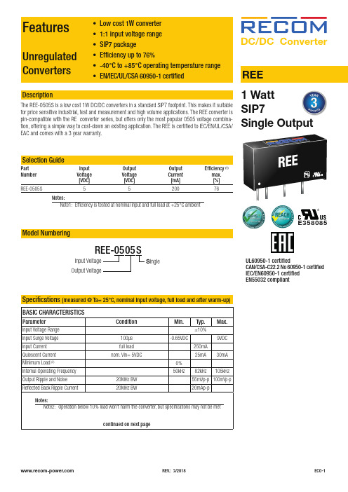
UL60950-1 certifiedCAN/CSA-C22.2 No 60950-1 certified IEC/EN60950-1 certified EN55032 compliantREE1 WattDescriptionFeaturesUnregulated ConvertersBASIC CHARACTERISTICSParameterCondition Min.Typ.Max.Input Voltage Range ±10%Input Surge Voltage 100µs -0.65VDC9VDCInput Current full load 250mA Quiescent Current nom. Vin= 5VDC25mA30mAMinimum Load (2)0%Internal Operating Frequency 50kHz82kHz 105kHzOutput Ripple and Noise 20MHz BW 55mVp-p 100mVp-pReflected Back Ripple Current20MHz BW20mAp-pcontinued on next pageSpecifications (measured @ Ta= 25°C, nominal input voltage, full load and after warm-up)Input Voltage Output VoltageREE-0505SE358085S ingleNotes:Note2: Operation below 10% load won‘t harm the converter, but specifications may not be metDC/DC Convert erSpecifications (measured @ Ta= 25°C, nominal input voltage, full load and after warm-up)REGULATIONSParameterCondition ValuesOutput Accuracy -2% typ. / ±5.0% max.Line Regulation low line to high line, full load±1.2% of 1.0% Vin typ.Load Regulation20% to 100%10% max.Tolerance Envelope+10%+5%Vnom+5%-2%-5%O u t p u t V o l t a g e [%]1050100Output Load [%]T y p i c a l Loa d L i n e1020304050607080901001008060409070503020100E f f i c i e n c y [%]Output Load [%]25155-5020100-10D e v i a t i o n [%]102030405060708090100Output Load [%]Efficiency vs. LoadDeviation vs. LoadSpecifications (measured @ Ta= 25°C, nominal input voltage, full load and after warm-up)ENVIRONMENTALParameterConditionValueOperating Temperature Range full derating (see graph)-40°C to +85°CMaximum Case Temperature +105°C Temeperature Coefficient ±0.05%/°C Thermal Impedance 0.1m/s, horizontal direction40°C/W Operating Altitude 2000m Operating Humidity non-condensing 95% RH max.Pollution Degree PD2MTBFaccording to MIL-HDBK-217F, G.B.+25°C +85°C2400 x 103 hours 650 x 103 hours-40-20020407060-30-10103050808590110100100806040907050302010O u t p u t L o a d [%]Ambient Temperature [°C]Derating GraphPROTECTIONSParameterConditionValueShort Circuit Protection (SCP)below 100m Ω1 second Isolation Voltage (3)I/P to O/Ptested for 1 second rated for 1 minute1kVDC 500VAC/60Hz Isolation Resistance 1G Ω min.Isolation Capacitance 75pF max.Insulation GradebasicNotes:Note3: For repeat Hi-Pot testing, reduce the time and/or the test voltageNote4: Refer to local wiring regulations if input over-current protection is also required. Recommended fuse: T1A slow blow typeSAFETY AND CERTIFICATIONSCertificate Type (Safety)Report/File Number StandardInformation Technology Equipment, General Requirements for Safety E358085-A4UL60950-1, 2nd Edition, 2007 CSA C22.2 No. 60950-1-07, 2nd Edition, 2007Information Technology Equipment, General Requirements for Safety1602031IEC60950-1:2005, 2nd Edition + A2:2013EN60950-1:2006 + A2:2013EAC RU-AT.49.09571TP TC 004/2011 RoHs 2+RoHS-2011/65/EU + AM-2015/863Specifications (measured @ Ta= 25°C, nominal input voltage, full load and after warm-up)PACKAGING INFORMATIONParameter Type Value Packaging Dimension (LxWxH)tube520.0 x 16.0 x 9.0mm Packaging Quantity25pcs Storage Temperature Range-55°C to +125°C Storage Humidity5% - 95%, RHThe product information and specifications may be subject to changes even without prior written notice.The product has been designed for various applications; its suitability lies in the responsibility of each customer. The products are not authorized for use in safety-critical applications without RECOM’s explicit written consent. A safety-critical application is an application where a failure may reasonably be expected to endanger or cause loss of life, inflict bodily harm or damage property. The applicant shall indemnify and hold harmless RECOM, its affiliated companies and its representatives against any damage claims in connection with the unauthorizeduse of RECOM products in such safety-critical applications.。
REC5-0515DRW中文资料
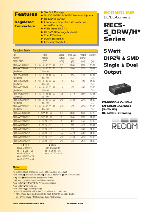
Single –Vin –Vin NC NC +Vout –Vout +Vin +Vin
Dual –Vin –Vin Com –Vout +Vout Com +Vin +Vin
Recommended Footprint Details
1.00 ø+0.15/0
22 23 2.54
NC = No Connection XX.X ± 0.5 mm XX.XX ± 0.25 mm
REC5-S_DRW/H* Series
2:1 & 4:1 ±2% max. ±0.3% max. ±0.6% max. 50mVp-p max. 120kHz typ. 200kHz typ. Pi Network see above 300mW max. 1000VDC min. 2000VDC min. see Application Notes 1000VDC min. 2000VDC min. 3000VDC min. see Application Notes 60pF typ. 1 GΩ min. Continuous, Auto Restart -40°C to +75°C (see Graph) -55°C to +125°C 95% RH Non-Conductive Plastic 20°C/W for metal case 13g 850 x 10 hours 206 x 103hours
ECONOLINE
DC/DC-Converter
REC5S_DRW/H* Series
5 Watt DIP24 & SMD Single & Dual Output
Selection Guide
瑞格电器应用有限公司高效无缝冷暖潜空暖气系统技术产品指南说明书

Technical Product GuideCompact & Quiet SolutionTable of Contents1.0PRODUCT OVERVIEW 32.0FEATURES AND BENEFITS 33.0PRODUCT NOMENCLATURE 64.0AHRI CERTIFICATION 65.0SYSTEM FEATURES 76.0USER CONTROL FUNCTIONS 87.0SYSTEM PERFORMANCE 98.0SOUND DATA 129.0ELECTRICAL DATA 1310.0MAJOR COMPONETS & WEIGHTS 1411.0DIMENSIONAL SPECIFICATIONS 1512.0CLEARANCE SPECIFICATIONS 2113.0EXTENDED PERFORMANCE RATINGS 2214.0ELECTRICAL WIRING 2815.0CONDENSATE REMOVAL 2916.0PRODUCT LIMITED WARRANTY 30PRODUCT OVERVIEWCompact, quiet and provides unmatched comfort in any room.The Gree Rio High-Efficiency Duct-free Mini-Split Heat Pump system is compact, quiet & provides unmatched comfort in any room. This system includes an indoor cabinet, outdoor compressor, wireless remote and remote cradle. Without needing duct work, installation is simple, fast & cost effective. In addition The Gree Rio provides quiet comfort & improved efficiency by eliminating heat loss inefficiencies of conventional central air conditioning systems.FEATURES AND BENEFITSHIGH EFFICIENCY G-10 INVERTER - The G10 Inverter uses a broad rangeof variable frequencies to drive the compressor, marking the highest level ofinverter control technology available today. Unlike conventional technologythat generally regulates room temperature by running at maximum capacity andthen shutting off completely, G10 Inverter technology eliminates these harshstarts/stops. This cutting edge functionality results in quicker arrival at desired temperatures and superior maintenance of consistent comfort levels. Higher efficiency and significant energy savings? Yes, it yields those too.HEAT PUMP ADVANTAGE – Gree heat pumps, powered by the G10 Inverter, provide the same heating capacity as electric heat, while using as little as 1/3 the electricity.WHISPER QUIET - Not only is the Rio systems energy efficient, it’s quiet too. Wall mounted units operate with sound levels starting as low as 32 dB(A).INTELLIGENT DEFROST - The Intelligent Defrost function increases room comfort and saves energy by eliminating unnecessary defrost cycles. In heating mode, the control system monitors the outdoor coil for frost buildup, and the system switches to defrost mode only when frost buildup is actually detected. This avoids unnecessary and wasteful defrosts.LOW VOLTAGE START UP – Having stable electrical power is not always an option. The Gree system will operate from 170v to 253v (230v model) and 104v to 127v (115v models) which is suitable for unstable power supply areas.SUBTLE APPEARANCE -Designed for a comfortable fit in virtually any living space. This slim compact cabinet sits inconspicuously on the wall, and blends into most interior designsUNIT DISPLAY – Rio wall mounted units have a large easy-to-read display and indicator lights giving instead feedback on room setpoint, operating mode and much more. The display can also be turned off based on your personal preference.MULTI-SPEED FAN – The indoor fan can run at up to four different speeds (Low, Medium, High or Turbo) for either COOLING or HEATING mode for maximum comfort and quiet operation.TIME GUARD - Among the system’s many safeties is a Time Guard function to prevent rapid cycling of the compressor. A protective five-minute time delay restricts compressor restarts after shutoff.POWER FAILURE MODE - Power interruptions are no problem. User selections and system parameters are stored in non-volatile memory. These parameters are retained during a power failure. When power is returned, the system will automatically return to the last operating mode.INTELLIGENT PRE-HEATING - The system guards against the annoying COLD BLOW in heating mode, and constantly monitors the discharge air temperature. It will delay the indoor fan until the indoor coil has warmed up to prevent blowing uncomfortable cool air into the room.WIRELESS IR REMOTE CONTROLLER - The Gree multi-functional infrared hand held wireless controller is sleek, ergonomically designed, easy to use and has a large backlit LCD display.MODE BUTTON - The units can be set to five different operating modes: HEAT, COOL, DRY, FAN ONLY and AUTO.Note: AUTO MODE has fixed setpoints of 68° F heating and 78° F cooling, which are notchangeable. The system will automatically select heating or cooling to maintain roomtemperature within this temperature band.TIMER MODE – The unit can be programmed to turned ON or OFF after a specific amount time. The time period is adjustable between one half and 24 hours.SWING LOUVER –The unit has adjustable swing louvers which can be controlled from the wired tether or wireless controllers. Vertical swing louver allows five different vertical (up & down) air discharge directions including Continuous Sweep. Maximize comfort by adjusting the direction of airflow in the room by moving the louvers up or down.PRIVACY LOCK MODE –Both wired tether and wireless controllers have a Privacy Lock to avert unauthorized access and stop tampering with system settings.SLEEP MODE –The unit will automatically adjust room temperature during sleep time. This slight change in temperature will not affect your comfort level due to the natural effects that sleeping has on the body, but it will save on energy consumption and will lower electric bills.FAHRENHEIT ° F / CELSIUS ° C - The wired tether and wireless controllers can be set to display in either °F or °C.POLYMERIC AIR FILTERS –Two-piece removable polymeric air filters easily slide in and out from the front of the indoor unit and are interchangeable. The front panel does not need to be removed to access or change the filters. The filters are washable and permanent.SELF-DIAGNOSIS –With an on-board computer using real-time diagnostics, the Gree system helps to prolong its own life. The automatic diagnosis feature continuously scans for unacceptable operating conditions or malfunctions. If such conditions occur, the system takes corrective action or stops. Fault codes are shown on the unit display to facilitate easy troubleshooting and repair. AGENCY LISTINGS - All systems are listed withAHRI (Air conditioning, Heating, and Refrigeration Institute) and are ETL Certified per UL Standards.5/7 YEAR LIMITED WARRANTY - Enjoy one of the most comprehensive warranties in the industry. Seven (7) years on compressor and Five (5) years on all parts.NOMENCLATUREAHRI CERTIFICATIONMODEL NUMBER BRAND AHRI CERTIFICATIONRIO09HP115V1A GREE 7077793RIO12HP115V1A GREE 7084752RIO09HP230V1A GREE 7077585RIO12HP230V1A GREE 7077586RIO18HP230V1A GREE 7077587RIO24HP230V1A GREE 7077588SYSTEM FEATURESModelRIO09HP115V1ARIO12HP115V1ARIO09HP230V1ARIO12HP230V1ARIO18HP230V1ARIO24HP230V1ANominal Cooling Capacity (Btu/H 9,000 12,000 9,000 12,000 18,000 24,000 Operating Voltage 115V 115V 208/230V 208/230V 208/230V 208/230V System TypeHeat Pump Heat Pump Heat Pump Heat Pump Heat Pump Heat Pump SYSTEM FEATURES Auxiliary Electrical HeaterNO NO NO NO NO NO Basepan With Electric HeaterNO NO NO NO NO NO Compressor With Electric HeaterNO NO YES YES NO NO Corrosion Protection Blue Fin Blue Fin Blue Fin Blue Fin Blue Fin Blue Fin Inverter TypeG10 G10 G10 G10 G10 G10 Intelligent Defrosting YES YES YES YES YES YES Intelligent Preheating YES YES YES YES YES YES LED Display Indoor UnitYES YES YES YES YES YES Low Ambient Cooling NO NO YES YES YES YES Low Ambient Heating YES YES YES YES YES NO Low Voltage Startup YES YES YES YES YES YES Memory/Power Failure RecoveryYES YES YES YES YES YES Multi Fan Speeds 4 Speeds 4 Speeds 4 Speeds 4 Speeds 4 Speeds 4 Speeds Self-DiagnosisYES YES YES YES YES YES PhotoCatalytic Filter NO NO NO NO NO NO Ventilation (Outdoor Air) NO NO NO NO NO NOAmbient Cooling Operating Range 64~113 F 64~113 F 5~109 F5~109 F5~109 F5~109 FAmbient Heating Operating Range5ºF ~75ºF5ºF ~75ºF5ºF ~75ºF 5ºF ~75ºF 5ºF ~75ºF 19~75 FUSER CONTROL FUNCTIONS Model RIO09HP115V1A RIO12HP115V1A RIO09HP230V1A RIO12HP230V1A RIO18HP230V1A RIO24HP230V1ANominal Cooling Capacity (Btu/H 9,000 12,000 9,000 12,000 18,000 24,000 Operating Voltage 115V 115V 208/230V 208/230V 208/230V 208/230V REMOTE CONTROLLER FUNCTIONSAuto Mode YES YES YES YES YES YES Auto Fan NO NO NO NO NO NO Auto Swing (Horizontal Auto Swing) NO NO NO NO NO NO Auto Swing (Vertical Auto Swing) YES YES YES YES YES YES Clock on Remote Controller NO NO NO NO NO NO Dry Mode YES YES YES YES YES YES Dry Anti-Mildew (X-Fan) Mode YES YES YES YES YES YES Energy Saving Mode NO NO NO NO NO NO Dirty Filter Alert NO NO NO NO NO NOI Feel Function NO NO NO NO NO NO Wired Controller Interface NO NO NO NO NO NO Lock on Remote Controller YES YES YES YES YES YES Room Temperature Display YES YES YES YES YES YES Sleep Mode YES YES YES YES YES YES Multi Sleep Modes Options NO NO NO NO NO NO Timer Mode YES YES YES YES YES YES Turbo Mode YES YES YES YES YES YESSYSTEM PERFORMANCEModel Numbers SEER EERCooling Capacity Dehumid-ification(Pts./Hr.)OutdoorTemperatureOperating Range Rated(BtuH)Range(BtuH)Min MaxRIO09HP115V1A 16 12.0 9,000 (3,500-11,000) 64 °F 113 °F RIO12HP115V1A 16 9.4 11,800 (3,300-12,500) 64 °F 113 °F RIO09HP230V1A 16 10.2 9,000 (3,800-11,500) 5 °F 109 °F RIO12HP230V1A 16 9.8 12,000 (3,300-12,500) 5 °F 109 °F RIO18HP230V1A 16 11.1 18,000 (4,500-21,000) 5 °F 109 °F RIO24HP230V1A 16 10.0 22,000 (6,400-24,000) 5 °F 109 °FModel Numbers HSPF COPHeating CapacityOutdoor TemperatureOperating Range Rated(BtuH)Range (BtuH) Min MaxRIO09HP115V1A 8.6 3.5 9,800 (2,500-11,000) 5 °F 75 °F RIO12HP115V1A 8.6 2.9 13,000 (3,400-13,500) 5 °F 75 °F RIO09HP230V1A 8.5 3.4 9,000 (3,300-11,500) 5 °F 75 °F RIO12HP230V1A 8.5 3.4 12,000 (3,400-12,500) 5 °F 75 °F RIO18HP230V1A 8.5 2.8 19,200 (4,000-23,000) 5 °F 75 °F RIO24HP230V1A 9.5 3.0 24,200 (4,100-26,600) 19 °F 75 °FNOTES:1.Ratings are based on: Cooling Standard: 80 F (26.7 C) db, 67 F (19.4 C) wb air entering indoor unit and 95F (35 C) db air entering outdoor unit. Heating Standard: 70 F (21.1 C) db air entering indoor unit and 47 F(8.3 C) db, 43 F (6.1 C) wb air entering outdoor unit.2.Ratings are based on 25 ft. (7.62 m) of interconnecting refrigerant lines.3.All system ratings are based on fan coil units operating at high fan speed. Consult Physical Data tables forair flows at selected fan speeds.LegendEER - Energy Efficiency RatioHSPF - Heating Seasonal Performance RatioSEER - Seasonal Energy Efficiency RatioCOP - Coefficient of PerformanceAIR FLOW PERFORMANCE Indoor UnitModel NumbersCooling (CFM) Heating (CFM)LowFanMediumFanHighFanTurboFanLowFanMediumFanHighFanTurboFanRIO09HP115V1AH 188 223 276 329 188 223 276 329 RIO12HP115V1AH 200 235 288 341 200 235 288 341 RIO09HP230V1AH 141 194 282 330 141 194 282 330 RIO12HP230V1AH 153 206 294 341 153 206 294 341 RIO18HP230V1AH 271 330 400 471 271 330 400 471 RIO24HP230V1AH 206 306 441 589 206 306 441 589Outdoor UnitModel Numbers Air Flow (CFM)RIO09HP115V1AO 1057RIO12HP115V1AO 1057RIO09HP230V1AO 942RIO12HP230V1AO 942RIO18HP230V1AO 1882RIO24HP230V1AO 1883Indoor Air ThrowModel Numbers Approximate Air Throw (ft.)Low Medium High TurboRIO09HP115V1AH NA NA 26 33RIO12HP115V1AH NA NA 26 33RIO09HP230V1AH NA NA 26 33RIO12HP230V1AH NA NA 26 33RIO18HP230V1AH NA NA 21 24RIO24HP230V1AH NA NA 21 31REFRIGERATION& PIPING SPECIFICATIONS REFRIGERANT CHARGEModel Number RefrigerantTypeFactory SystemCharge (oz.)Max Total PipeLength Without AddingRefrigerant (ft.)AdditionalCharge Level(oz./ft.)RIO09HP115V1AO R-410A 37.5 25 0.2 RIO12HP115V1AO R-410A 41.1 25 0.2 RIO09HP230V1AO R-410A 26.1 25 0.2 RIO12HP230V1AO R-410A 35.3 25 0.2RIO18HP230V1AO R-410A 45.9 250.2RIO24HP230V1AO R-410A 54.7 25 0.2 REFRIGERANT PIPING LENGTHSModel Number Min. Pipe Lengthfor System (ft.) Max Pipe Length forSystem (ft.)Max Elevation betweenOutdoor & Indoor Units (ft.)RIO09HP115V1AO 10 66 33 RIO12HP115V1AO 10 66 33 RIO09HP230V1AO 10 50 33 RIO12HP230V1AO 10 50 33 RIO18HP230V1AO 10 82 33 RIO24HP230V1AO 10 82 33SOUND DATA Indoor High Wall UnitsModel NumbersLow Fan Medium Fan High Fan Turbo Fan SoundPower(dBA)SoundPressure(dBA)SoundPower(dBA)SoundPressure(dBA)SoundPower(dBA)SoundPressure(dBA)SoundPower(dBA)SoundPressure(dBA)RIO09HP115V1AH 42 32 45 35 47 37 50 40 RIO12HP115V1AH 42 32 45 35 47 37 50 40 RIO09HP230V1AH 36 26 42 32 48 38 53 43 RIO12HP230V1AH 38 28 43 33 49 39 54 44 RIO18HP230V1AH 44 34 48 38 53 43 58 48 RIO24HP230V1AH 44 34 49 39 53 43 59 49Outdoor UnitModel Numbers Sound Power(dBA)Sound Pressure(dBA)RIO09HP115V1AO 63 53RIO12HP115V1AO 65 55RIO09HP230V1AO 59 49RIO12HP230V1AO 62 52RIO18HP230V1AO 66 56RIO24HP230V1AO 63 53Note:1.Sound pressure ratings are estimated sound pressure measurements, 3 feet from unit.2.Sound power ratings are per AHRI 270 and AHRI 350ELECTRICAL DATA Outdoor UnitModel Numbers Rated Power Supply(volt-phase-hz)Voltage Range(volts)Rated Input Power (watts)Cooling HeatingRIO09HP115V1AO 115v-1ph-60hz 104-127 750 830 RIO12HP115V1AO 115v-1ph-60hz 104-127 1260 1320 RIO09HP230V1AO 208/230v-1ph-60hz 187-253 880 770 RIO12HP230V1AO 208/230v-1ph-60hz 187-253 1620 1050 RIO18HP230V1AO 208/230v-1ph-60hz 187-253 1620 2400 RIO24HP230V1AO 208/230v-1ph-60hz 187-253 2200 2800Outdoor UnitModel NumbersRated Input Current (amps) Min. CircuitAmp. (MCA)Max FuseSize (Amps) Cooling HeatingRIO09HP115V1AO 9.0 9.5 13 20 RIO12HP115V1AO 15.0 15.5 15 25 RIO09HP230V1AO 3.9 3.4 10 15 RIO12HP230V1AO 5.4 4.7 10 15 RIO18HP230V1AO 7.9 11.8 15 25 RIO24HP230V1AO 11.5 13.0 16 25Model NumbersCompressor Outdoor Fan Indoor FanRLA(amps)LRA(amps)RLA(amps)Input Power(Watts)RLA(amps)Input Power(Watts)RIO09HP115V1AO 9.8 25.0 0.2 30 0.4 10 RIO12HP115V1AO 11.2 25.0 0.3 30 0.4 10 RIO09HP230V1AO 7.3 16.5 0.3 21 0.2 15 RIO12HP230V1AO 7.3 16.5 0.3 21 0.2 15 RIO18HP230V1AO 10.9 27.0 0.6 60 0.3 20 RIO24HP230V1AO 12.4 41.0 0.6 60 0.4 35Legend:RLA – Rated Load AmpsFLA – Full Load AmpsLRA – Locked Rotor AmpsMCA – Min. Circuit AmpsINDOOR UNIT MAJOR COMPONETS Model Numbers Air Filter Fan Motor Fan TypeRIO09HP115V1AH Polymeric Mesh AC Sync Cross flow RIO12HP115V1AH Polymeric Mesh AC Sync Cross flow RIO09HP230V1AH Polymeric Mesh AC Sync Cross flow RIO12HP230V1AH Polymeric Mesh AC Sync Cross flow RIO18HP230V1AH Polymeric Mesh AC Sync Cross flow RIO24HP230V1AH Polymeric Mesh AC Sync Cross flowOUTDOOR UNIT MAJOR COMPONETSModel Numbers Compressor MeteringDeviceInverterRIO09HP115VA1O Rotary EXV G10 RIO12HP115VA1O Rotary EXV G10 RIO09HP230VA1O Rotary EXV G10 RIO12HP230VA1O Rotary EXV G10 RIO18HP230VA1O Rotary EXV G10 RIO24HP230VA1O Rotary EXV G10PRODUCT WEIGHTModel NumbersOutdoor Unit Indoor UnitNet Operating(lbs.)Gross Shipping(lbs.)Net Operating(lbs.)Gross Shipping(lbs.)RIO09HP115V1A 75 84 19 26 RIO12HP115V1A 75 84 19 26 RIO09HP230V1A 64 73 19 25 RIO12HP230V1A 68 77 20 27 RIO18HP230V1A 106 117 27 35 RIO24HP230V1A 115 126 33 44Model No: RIO09HP115V1A 9,000 BtuH 115VLiquid Line Valve 1/4-in OD FlaredGas Line Valve 3/8-in OD FlaredDrain Connector 5/8-in ODLiquid Line Valve 1/4-in OD FlaredGas Line Valve 3/8-in OD FlaredModel No: RIO12HP115V1A 12,000 BtuH 115VLiquid Line Valve 1/4-in OD FlaredGas Line Valve 3/8-in OD FlaredDrain Connector 5/8-in ODLiquid Line Valve 1/4-in OD FlaredGas Line Valve 3/8-in OD FlaredModel No: RIO09HP230V1A 9,000 BtuH 230VLiquid Line Valve 1/4-in OD FlaredGas Line Valve 3/8-in OD FlaredDrain Connector 5/8-in ODLiquid Line Valve 1/4-in OD FlaredGas Line Valve 3/8-in OD FlaredModel No: RIO12HP230V1A 12,000 BtuH 230VLiquid Line Valve 1/4-in OD FlaredGas Line Valve 3/8-in OD FlaredDrain Connector 5/8-in ODLiquid Line Valve 1/4-in OD FlaredGas Line Valve 3/8-in OD FlaredModel No: RIO18HP230V1A 18,000 BtuH 230VLiquid Line Valve 1/4-in OD FlaredGas Line Valve 1/2-in OD FlaredDrain Connector 5/8-in ODLiquid Line Valve 1/4-in OD FlaredGas Line Valve 1/2-in OD FlaredModel No: RIO24HP230V1A 24,000 BtuH 230VLiquid Line Valve 1/4-in OD FlaredGas Line Valve 1/2-in OD FlaredDrain Connector 5/8-in ODLiquid Line Valve 1/4-in OD FlaredGas Line Valve 1/2-in OD FlaredCLEARANCE SPECIFICATIONSIndoor Minimum Clearance*Inch (mm)Outdoor Unit Minimum Clearance*OutdoorMinimum DistanceUnitA 20 in 508 mmB 20in 508 mmC 78 in 1,981 mmD 12 in 305 mmE 12in 305 mm*All ModelsModel No: RIO09HP115V1A 9,000 BtuH 115VCOOLING PERFORMANCEOutdoor Ambient Temperature (DB)Indoor Entering Air Temperatures (DB) 50% RH62 F 67 F 72 FTC SHC TC SHC TC SHC25 F NA NA NA NA NA NA 35 F NA NA NA NA NA NA 45 F NA NA NA NA NA NA 55 F NA NA NA NA NA NA 65F 9,569 7,434 10,520 7,985 11,165 8,152 75F 9,179 7,176 9,910 7,614 10,642 7,859 85F 8,810 7,013 9,445 7,289 10,266 7,666 95F 8,370 6,688 9,000 7,191 9,846 7,394 105F 7,912 6,436 8,532 6,809 9,274 7,115 115F 7,458 6,166 7,911 6,423 8,450 6,629HEATING PERFORMANCEOutdoor Ambient Temperature (DB) (80% RH)Indoor Entering Air Temperatures (DB)65 F 70 F 75 FTC SHC TC SHC TC SHC5F 8,239 8,239 7,881 7,881 7,629 7,62915F 8,926 8,926 8,239 8,239 8,231 8,23125F 9,439 9,439 9,631 9,631 9,559 9,55935F 10,911 10,911 11,392 11,392 10,889 10,88945F 12,357 12,357 12,243 12,943 12,386 12,38655F 13,368 13,368 13,116 13,116 12,596 12,59665F 13,350 13,350 13,203 13,203 12,856 12,856 TC- Total Capacity (BtuH) SHC- Sensible Capacity (BtuH)Capacity data is based on the following conditions:Cooling Nominal Test Conditions Heating Normal Test Conditions Indoor: 80°F DB/67°F WB Indoor: 70°F DB/60°F WBOutdoor: 95°F DB/75°F WB Outdoor: 47°F DB/43°F WModel No: RIO12HP115V1A 12,000 BtuH 115VCOOLING PERFORMANCEOutdoor Ambient Temperature (DB)Indoor Entering Air Temperatures (DB) 50% RH62 F 67 F 72 FTC SHC TC SHC TC SHC25F NA NA NA NA NA NA 35F NA NA NA NA NA NA 45F NA NA NA NA NA NA 55F NA NA NA NA NA NA 65F 12,754 9,920 14,043 10,641 14,890 10,887 75F 12,262 9,571 13,210 10,141 14,187 10,487 85F 11,764 9,347 12,602 9,737 13,650 10,259 95F 11,162 8,916 12,005 9,581 13,125 9,855 105F 10,556 8,571 11,370 9,079 12,361 9,496 115F 9,957 8,204 10,556 8,563 11,289 8,822HEATING PERFORMANCEOutdoor Ambient Temperature (DB) (80% RH)Indoor Entering Air Temperatures (DB)65 F 70 F 75 FTC SHC TC SHC TC SHC5F 9,221 9,221 8,663 8,663 8,436 8,43615F 11,598 11,598 10,968 10,968 10,619 10,61925F 11,845 11,845 11,683 11,683 11,476 11,47635F 12,876 12,876 12,642 12,642 12,535 12,53545F 14,195 14,195 13,989 13,989 13,546 13,54655F 14,513 14,513 14,245 14,245 14,128 14,12865F 14,459 14,459 14,375 14,375 14,274 14,274 TC- Total Capacity (BtuH) SHC- Sensible Capacity (BtuH)Capacity data is based on the following conditions:Cooling Nominal Test Conditions Heating Normal Test Conditions Indoor: 80°F DB/67°F WB Indoor: 70°F DB/60°F WBOutdoor: 95°F DB/75°F WB Outdoor: 47°F DB/43°F WModel No: RIO09HP230V1A 9,000 BtuH 230VCOOLING PERFORMANCEOutdoor Ambient Temperature (DB)Indoor Entering Air Temperatures (DB) 50% RH62 F 67 F 72 FTC SHC TC SHC TC SHC25F 11,073 8,222 11,968 8,665 12,794 9,211 35F 10,821 8,212 11,524 8,412 12,083 8,736 45F 10,286 7,900 11,000 8,162 11,786 8,544 55F 9,903 7,665 10,560 7,920 11,320 8,264 65F 9,565 7,432 10,525 7,988 11,160 8,158 75F 9,189 7,186 9,900 7,613 10,648 7,858 85F 8,820 7,003 9,450 7,295 10,260 7,664 95F 8,370 6,688 9,000 7,191 9,846 7,394 105F 7,920 6,431 8,530 6,807 9,270 7,119 115F 7,469 6,155 7,919 6,415 8,459 6,624HEATING PERFORMANCEOutdoor Ambient Temperature (DB) (80% RH)Indoor Entering Air Temperatures (DB)65 F 70 F 75 FTC SHC TC SHC TC SHC5F 7,435 7,435 7,017 7,017 6,845 6,84515F 7,947 7,947 7,250 7,250 7,206 7,20625F 8,432 8,432 8,003 8,003 7,548 7,54835F 8,903 8,903 8,240 8,240 7,894 7,89445F 9,368 9,368 9,050 9,050 8,502 8,50255F 9,380 9,380 9,109 9,109 8,710 8,71065F 9,336 9,336 9,199 9,199 8,916 8,916 TC- Total Capacity (BtuH) SHC- Sensible Capacity (BtuH)Capacity data is based on the following conditions:Cooling Nominal Test Conditions Heating Normal Test Conditions Indoor: 80°F DB/67°F WB Indoor: 70°F DB/60°F WBOutdoor: 95°F DB/75°F WB Outdoor: 47°F DB/43°F WModel No: RIO12HP230V1A 12,000 BtuH 230VCOOLING PERFORMANCEOutdoor Ambient Temperature (DB)Indoor Entering Air Temperatures (DB) 50% RH62 F 67 F 72 FTC SHC TC SHC TC SHC25F 14,764 10,962 15,958 11,553 17,058 12,282 35F 14,428 10,949 15,365 11,216 16,111 11,648 45F 13,715 10,533 14,666 10,883 15,714 11,393 55F 13,204 10,219 14,080 10,560 15,094 11,018 65F 12,754 9,910 14,033 10,651 14,880 10,877 75F 12,252 9,581 13,200 10,151 14,197 10,477 85F 11,760 9,337 12,600 9,727 13,680 10,219 95F 11,160 8,917 12,000 9,588 13,128 9,859 105F 10,560 8,575 11,374 9,076 12,360 9,492 115F 9,959 8,206 10,559 8,553 11,279 8,832HEATING PERFORMANCEOutdoor Ambient Temperature (DB) (80% RH)Indoor Entering Air Temperatures (DB)65 F 70 F 75 FTC SHC TC SHC TC SHC5F 9,907 9,907 9,350 9,350 9,121 9,12115F 10,590 10,590 9,661 9,661 9,603 9,60325F 11,236 11,236 10,665 10,665 10,058 10,05835F 11,864 11,864 10,981 10,981 10,520 10,52045F 12,483 12,483 12,060 12,060 11,329 11,32955F 12,500 12,500 12,139 12,139 11,608 11,60865F 12,441 12,441 12,259 12,259 11,881 11,881 TC- Total Capacity (BtuH) SHC- Sensible Capacity (BtuH)Capacity data is based on the following conditions:Cooling Nominal Test Conditions Heating Normal Test Conditions Indoor: 80°F DB/67°F WB Indoor: 70°F DB/60°F WBOutdoor: 95°F DB/75°F WB Outdoor: 47°F DB/43°F WModel No: RIO18HP230V1A 18,000 BtuH 230VCOOLING PERFORMANCEOutdoor Ambient Temperature (DB)Indoor Entering Air Temperatures (DB) 50% RH62 F 67 F 72 FTC SHC TC SHC TC SHC25F 22,145 16,443 23,936 17,330 25,587 18,422 35F 21,641 16,423 23,047 16,825 24,167 17,473 45F 20,572 15,799 22,000 16,324 23,571 17,089 55F 19,805 15,329 21,119 15,839 22,640 16,528 65F 19,130 14,864 21,049 15,977 22,320 16,316 75F 18,378 14,371 19,800 15,226 21,296 15,716 85F 17,640 14,006 18,900 14,591 20,520 15,329 95F 16,740 13,375 18,000 14,382 19,692 14,789 105F 15,840 12,862 17,060 13,614 18,540 14,239 115F 14,939 12,309 15,839 12,829 16,919 13,248HEATING PERFORMANCEOutdoor Ambient Temperature (DB) (80% RH)Indoor Entering Air Temperatures (DB)65 F 70 F 75 FTC SHC TC SHC TC SHC5F 15,978 15,978 15,080 15,080 14,710 14,71015F 17,079 17,079 15,581 15,581 15,488 15,48825F 18,121 18,121 17,200 17,200 16,221 16,22135F 19,133 19,133 17,709 17,709 16,966 16,96645F 20,133 20,133 19,450 19,450 18,272 18,27255F 20,160 20,160 19,577 19,577 18,720 18,72065F 20,064 20,064 19,771 19,771 19,162 19,162 TC- Total Capacity (BtuH) SHC- Sensible Capacity (BtuH)Capacity data is based on the following conditions:Cooling Nominal Test Conditions Heating Normal Test Conditions Indoor: 80°F DB/67°F WB Indoor: 70°F DB/60°F WBOutdoor: 95°F DB/75°F WB Outdoor: 47°F DB/43°F WModel No: RIO24HP230V1A 24,000 BtuH 230VCOOLING PERFORMANCEOutdoor Ambient Temperature (DB)Indoor Entering Air Temperatures (DB) 50% RH62 F 67 F 72 FTC SHC TC SHC TC SHC25F 27,066 20,097 29,255 21,181 31,273 22,516 35F 26,450 20,073 28,169 20,564 29,537 21,356 45F 25,144 19,310 26,889 19,951 28,809 20,886 55F 24,206 18,736 25,812 19,359 27,671 20,201 65F 23,381 18,167 25,727 19,527 27,280 19,942 75F 22,462 17,565 24,200 18,610 26,028 19,209 85F 21,560 17,119 23,100 17,833 25,080 18,735 95F 20,460 16,347 22,000 17,578 24,068 18,075 105F 19,360 15,720 20,851 16,640 22,660 17,403 115F 18,259 15,045 19,359 15,680 20,678 16,191HEATING PERFORMANCEOutdoor Ambient Temperature (DB) (80% RH)Indoor Entering Air Temperatures (DB)65 F 70 F 75 FTC SHC TC SHC TC SHC5F 20,004 20,004 18,880 18,880 18,417 18,41715F 21,383 21,383 19,508 19,508 19,390 19,39025F 22,688 22,688 21,534 21,534 20,309 20,30935F 23,954 23,954 22,172 22,172 21,242 21,24245F 25,206 25,206 24,351 24,351 22,876 22,87655F 25,240 25,240 24,510 24,510 23,437 23,43765F 25,120 25,120 24,753 24,753 23,990 23,990 TC- Total Capacity (BtuH) SHC- Sensible Capacity (BtuH)Capacity data is based on the following conditions:Cooling Nominal Test Conditions Heating Normal Test Conditions Indoor: 80°F DB/67°F WB Indoor: 70°F DB/60°F WBOutdoor: 95°F DB/75°F WB Outdoor: 47°F DB/43°F WELECTRICAL WIRINGThe main power is supplied to the outdoor unit. System must be on a single dedicated circuit. Use appropriate wire size and circuit breaker (or fuse) size for proper system overcurrent protection. Follow all local building codes and NEC (National Electrical Code) regulations.Interconnecting Cable Wiring DiagramThe indoor unit is powered by the outdoor unit. The interconnecting cable between the outdoor and indoor unit must be a 14/4 AWG stranded copper conductors THHN 600V unshielded wire. The interconnecting cable should not be buried underground and must be recognized by UL or ETL and CSA certified.Note: Use shield cable if installation is in close proximity of RF and EMI transmitting devices.Local codes may require a disconnect switch within sight of the indoor unit. For these installations, use a DFS Disconnect Switch Accessory Kit (Part No: DFS-SWITCH-A) to break wires going to the N(1), 2, 3 terminals on the indoor unit, as shown in the wiring diagram below:CONDENSATE REMOVALInstall condensate drain to safely and effectively route condensate water to a safe location. Use a flexible condensate drain hose to fit over the factory 5/8-inch (16mm) drainage port. The high wall indoor units have an internal condensate trap. Adding an external trap is not required.All condensate drains must meet local codes and regulations. If adequate gravity drainage cannot be provided, a field-installed condensate pump must be used. Refer to manufacturer’s installation instructions, specifications and operating details supplied with condensate pump.Typical Condensate Pump Wiring DiagramLIMITED WARRANTY STATEMENTEffective on new GREE Ductless purchases on or after March 1, 2013Ductless Heat Pump Mini-Split SystemsRIO09HP115V1A RIO12HP115V1ARIO09HP230V1A RIO12HP230V1ARIO18HP230V1A RIO24HP230V1AGREE distributor (hereinafter “Company”) warrants this product against failure due to defect in materials or workmanship under normal use and maintenance as follows. All warranty periods begin on the date of original installation. If the date cannot be verified, the warranty period begins one hundred twenty (120) days from date of manufacture. If a part fails due to defect during the applicable warranty period Company will provide a new or remanufactured part, at Company’s option, to replace the failed defective part at no charge for the part. This limited warranty is subject to all provisions, conditions, limitations and exclusions listed below.• A warranty period of Seven (7) years on compressor to the original registered end-user.• A warranty period of Five (5) years on all parts to the original registered end user.• A warranty period of One (1) year on the remote control provided with the original unit.•Limited warranty applies only to systems that are properly installed by a state certified or licensed HVAC contractor, under applicable local and state law in accordance with all applicable building codes and permits; GREE installation and operation instructions and good trade practices.•Warranty applies only to products remaining in their original installation location.•Defective parts must be returned to the distributor through a registered servicing dealer for credit.。
艾森 ESR5 安全传感器门控制器说明书
Eaton 119380Eaton ESR5 Safety relay emergency stop/protective door, 230VAC, 3 enabling paths ESR5-NO-31-230VACGeneral specificationsEaton ESR5 Safety relay 119380ESR5-NO-31-230VAC 4015081175062114.5 mm 99 mm 22.5 mm 0.181 kgUL 508 IEC/EN 60204 CE IEC 62061UL Category Control No.: NKCR; NKCR7IEC 61508, Parts 1-7 UL2014/30/EU UL File No.: E29184CSA Class No.: 3211-83; 3211-03 EN 50178UL report applies to both US and CanadaCSA-C22.2 No. 14-95 EN ISO 13849-1Certified by UL for use in Canada Machines 2006/42/EGProduct NameCatalog Number Model CodeEANProduct Length/Depth Product Height Product Width Product Weight Certifications0 A230 VIs the panel builder's responsibility. The specifications for the switchgear must be observed.230 V AC (power supply)230 V ACApprox. 24 V DC at input, starting and feedback circuit0 VMeets the product standard's requirements.Top-hat rail fixing (according to IEC/EN 60715, 35 mm)Rail mounting possible230 VNoneStatus indication of SmartWire-DT network: Green LED240 Months (High Demand)78 Months (Low Demand)795 - 1080 hPa (operation)230 VMeets the product standard's requirements.easySafety ES4P Safety Relay ESR5 - brochureDA-DC-00004573.pdfDA-DC-00004581.pdfeaton-safety-relays-esr5-safety-relay-characteristic-curve-006.epseaton-safety-relays-relay-esr5-safety-relay-dimensions-002.eps eaton-general-esr5-safety-relay-symbol-002.epseaton-general-esr5-safety-relay-symbol.epseaton-safety-relays-relay-esr5-safety-relay-3d-drawing-002.eps DA-CE-ETN.ESR5-NO-31-230VACIL05013032ZMN049012_ENDA-CD-esr5_no21_no31_24vDA-CS-esr5_no21_no31_24vRated operational current for specified heat dissipation (In) Operating voltage at AC, 50 Hz - min10.11 Short-circuit ratingRated operational voltageRated control supply voltage (Us) at AC, 50 Hz - min10.4 Clearances and creepage distancesMounting methodNumber of outputs (safety related, delayed, semiconductors) Control voltage 1 - minSafety type (IEC 61496-1)LED indicatorProoftestAir pressureOperating voltage at AC, 60 Hz - max10.2.3.1 Verification of thermal stability of enclosures Ambient storage temperature - min BrochuresCertification reports Characteristic curve DrawingseCAD model Installation instructions Manuals and user guides mCAD model-40 °COperating voltage at AC, 50 Hz - max230 VFitted with:Feedback circuitApproval according to ULApproval for TÜVStart inputDetachable clampsVibration resistance10 - 150 Hz, Amplitude: 0.15 mm, Acceleration: 2 g, (IEC/EN 60068-2-6)Rated control supply voltage (Us) at AC, 50 Hz - max26.4 VStop category (IEC 60204)Control voltage 1 - max230 VAmbient operating temperature - max55 °CControl voltage 1 typeACSwitching frequencyMax. 0.5 Hz, Input dataFeatures3 Non-delayed enable current pathsReinforced insulationSafe insulationAutomatically/manually monitored start6 kV between A1-A2 / logic / enable and signal current paths Basic insulationReset time20 ms (two-channel)Normally 150 ms (single-channel)Recovery time1000 msAmbient operating temperature - min-20 °CSupply voltage at AC, 60 Hz - max230 V10.6 Incorporation of switching devices and components Does not apply, since the entire switchgear needs to be evaluated.Power supply circuit2.9 W (DC operated)5.8 W (AC operated 50/60 Hz)10.2.6 Mechanical impactDoes not apply, since the entire switchgear needs to be evaluated.10.3 Degree of protection of assembliesDoes not apply, since the entire switchgear needs to be evaluated.Voltage typeACQuadratic summation current72 A² (ITH² = I1² + I2² + I3²)Category (EN 954-1)4Nominal current35 AProduct categoryElectronic safety relaysTerminal capacity1 x (0.25 – 2.5) mm², flexible with ferrule2 x (0.25 – 1) mm², flexible with ferrule24 - 12 AWG, solid or stranded1 x (0.2 – 2.5) mm², solid2 x (0.2 – 1) mm², solidHeat dissipation capacity Pdiss0 WControl voltage 2 typeACShort-circuit current0.7 A, Input dataPower lossNormally 5.43 WPick-up time40 ms typ. (at Uₑ in manual mode)300 ms typ. (at Uₑ in automatic mode)40 ms typ. (K1, K2 - for UN manual operation)300 ms typ. (K1, K2 - for UN automatic mode)330 ms typ. (if actuated via A1)Inrush current0.1 - 6 A10.9.2 Power-frequency electric strengthIs the panel builder's responsibility.Degree of protectionInstallation location: ≥ IP54Enclosure: IP20Terminals: IP20IP20Overvoltage categoryIIINumber of inputsOne- and two-channelAmbient storage temperature - max85 °CPollution degree2Release-delay - max0 sNumber of outputs (safety related, undelayed, semiconductors) 0Safety parameter (IEC 62061)SILCL 3, Safety integrity level claim limitSIL 3, Safety integrity levelCat. 4, CategorySIL 3, Safety integrity level, In accordance with IEC 61508 1.89 x 10⁻¹⁰, PFHd, Probability of failure per hourRated impulse withstand voltage (Uimp)4000 V ACFunctions1-channel2-channelBreaking power48 W max., inductive load (τ = 40 ms), at 24 V DC68 W max., resistive load (τ = 0 ms), at 110 V DC33 W max., inductive load (τ = 40 ms), at 220 V DC230 W max., resistive load (τ = 0 ms), at 48 V DC40 W max., inductive load (τ = 40 ms), at 48 V DC88 W max., resistive load (τ = 0 ms), at 220 V DC35 W max., inductive load (τ = 40 ms), at 110 V DC144 W max., resistive load (τ = 0 ms), at 24 V DC2000 VA, max., resistive load (τ = 0 ms), at 250 V ACSIL (IEC 61508)3Tightening torque0.6 Nm, Screw terminalsOperating voltage at DC - max0 VTypeEmergency stop category 0;emergency switching offFeedback circuitProtective door10.2.2 Corrosion resistanceMeets the product standard's requirements.10.2.4 Resistance to ultra-violet (UV) radiationMeets the product standard's requirements.10.2.7 InscriptionsMeets the product standard's requirements.Number of outputs (signaling function, delayed, semiconductors) 0Environmental conditionsClearance in air and creepage distances according to EN 50178, UL 508, CSA C22.2, No. 14-95Condensation: Non-condensingCurrent consumption22 mA, ACModelBasic deviceOperating voltage at DC - min0 VRelease-delay - min0 s10.12 Electromagnetic compatibilityIs the panel builder's responsibility. The specifications for the switchgear must be observed.10.2.5 LiftingDoes not apply, since the entire switchgear needs to be evaluated.Stripping length (main cable)7 mmSwitching capacityIn accordance with IEC 60947-5-1, Outputs0.1 W5 A at 360 O/h, AC-15 at 230 V, Outputs5 A at 360 O/h, DC-13 at 24 V, OutputsControl voltage 2 - max230 VInput∞ ms, Simultaneity for inputs 1/2Rated control supply voltage (Us) at DC - min0 VNumber of outputs (signaling function, delayed) with contact10.8 Connections for external conductorsIs the panel builder's responsibility.Control voltage 2 - min230 VVoltage type of operating voltageACProtectionFinger and back-of-hand proof, Protection against direct contact when actuated from front (EN 50274)Switching voltage250 VSupply voltage at DC - min0 VClimatic proofingDamp heat, constant, to IEC 60068-2-3Dry heat to IEC 60068-2-2Emitted interferenceAccording to EN 61000-6-4Static heat dissipation, non-current-dependent Pvs5.43 WRated control supply voltage (Us) at DC - max0 VNumber of outputs (signaling function, undelayed) with contact 110.9.3 Impulse withstand voltageIs the panel builder's responsibility.Resistance11 Ω (impedance)10.5 Protection against electric shockDoes not apply, since the entire switchgear needs to be evaluated.Supply voltage at DC - max0 VMounting positionAs requiredSafety parameter (EN ISO 13849-1)PL e, Performance level230,000 switching cycles, B10dCat. 4, CategoryElectric connection typeScrew connectionNumber of outputs (signaling function, undelayed, semiconductors)10.13 Mechanical functionThe device meets the requirements, provided the information in the instruction leaflet (IL) is observed.10.9.4 Testing of enclosures made of insulating materialIs the panel builder's responsibility.Heat dissipation per pole, current-dependent Pvid0 WSafety performance level (EN ISO 13849-1)Level eShort-circuit protectionFuse 4 A gL/gG (Signal current paths), For output circuits, ExternalFuse 10 A gL/gG (Enable current paths), For output circuits, ExternalShort-circuit proof, 115 V/230 V, Fuse for control circuit supply, Control circuitNumber of outputs (safety related, delayed) with contactSupply voltage at AC, 60 Hz - min230 VOperating temperature - min-20 °CUninterrupted current6 A N/O, Limiting continuous current5 A N/C, Limiting continuous currentEquipment heat dissipation, current-dependent Pvid0 WRated switch current4 ASuitable forModule used to safely interrupt electrical circuitsMonitoring of position switchesSafety relay for monitoring emergency stop and protective door switchMonitoring of emergency-stop circuitsPower consumption5.43 WInterference immunityAccording to EN 61000-6-2Operating temperature - max55 °C10.2.3.2 Verification of resistance of insulating materials to normal heatMeets the product standard's requirements.10.2.3.3 Resist. of insul. mat. to abnormal heat/fire by internal elect. effectsMeets the product standard's requirements.Connection typeM3 screw terminalsLifespan, mechanical10,000,000 OperationsVoltage type of supply voltageACRelative humidity< 75 %Supply voltage at AC, 50 Hz - min230 VRated control supply voltage (Us) at AC, 60 Hz - min20.4 V10.7 Internal electrical circuits and connectionsIs the panel builder's responsibility.Supply voltage at AC, 50 Hz - max230 V10.10 Temperature riseThe panel builder is responsible for the temperature rise calculation. Eaton will provide heat dissipation data for the devices.MaterialEnclosure: Polyamide (PA), not reinforcedContacts: silver tin oxide, gold plated (AgSnO2, 0.2 µ m Au)Number of outputs (safety related, undelayed) with contact3Permissible total cable resistance50 Ω (input and starting circuits for UN)Operating voltage at AC, 60 Hz - min230 VScrewdriver size2, Terminal screw, Pozidriv screwdriver0.6 x 3.5 mm, Terminal screwsDuty factor100 %Rated control supply voltage (Us) at AC, 60 Hz - max230 VShort-circuit protection rating10A gL/gG, NEOZED (N/O), Output fuse, External, Output data 6A gL/gG, NEOZED (N/C), Output fuse, External, Output dataMounting width22.5 mmAltitudeMax. 2000 mRated insulation voltage (Ui)250 VEaton Corporation plc Eaton House30 Pembroke Road Dublin 4, Ireland © 2023 Eaton. All Rights Reserved. Eaton is a registered trademark.All other trademarks areproperty of their respectiveowners./socialmedia。
- 1、下载文档前请自行甄别文档内容的完整性,平台不提供额外的编辑、内容补充、找答案等附加服务。
- 2、"仅部分预览"的文档,不可在线预览部分如存在完整性等问题,可反馈申请退款(可完整预览的文档不适用该条件!)。
- 3、如文档侵犯您的权益,请联系客服反馈,我们会尽快为您处理(人工客服工作时间:9:00-18:30)。
40 20 0
5 Watt DIP24 & SMD Single & Dual Output
EN-60950-1 Certified UL-60950-1 Certified EN-60601-1 Certified
4:1 Input (REC5-S/DRWZ(H4/H6)) xx = 9-36Vin = 24 xx = 18-72Vin = 48
Derating-Graph
(Ambient Temperature)
4000VDC min. see Application Notes 6000VDC min. see Application Notes 60pF typ. 1 GΩ min.
Output Power (%)
100 80 (3W) 60
Single
Efficiency / Load
100 80 60 40
Single
Efficiency / Load
100 80 60
1212
1209
2412
2405
1205
123.3 Efficiency %
40 20 0
243.3
Efficiency %
20 0
0% 20% 40% 60% Total Output current (%)
ECONOLINE
DC/DC-Converter
REC5S_DRW/H4, H6 Series
Efficiency (%) 75-77 79-81 72 82-83 73 84-85 74 85-86 75 79-81 72 84-85 74 85-86 75 75-76 81-82 82-83 83-84 84-85 81-82 82-83 84-85
元器件交易网
Features
Regulated Converters
● ● ● ● ● ● ● ● ●
UL-60950-1 / CSA C22.2 certified 5W DIP Package 4kVDC & 6kVDC Isolation Regulated Output Continuous Short Circuit Protection Wide Input 2:1 & 4:1 UL94V-0 Package Material 100% Burned In Efficiency to 86%
REC5-S_DRW/H4,H6 Series
2:1 & 4:1 ±2% max. ±0.3% max. ±0.6% max. 50mVp-p max. 120kHz typ. 200kHz typ. Pi Network see above 300mW max.
Load Regulation (for output load current change from 20% to 100%) Output Ripple and Noise (0,1µF capacitor on output, 20MHz BW) Operating Frequency at Full Load 2:1 input (at nominal input voltage) 4:1 input Input Filter Efficiency at Full Load No Load Power Consumption Isolation Voltage Rated Working Voltage Isolation Voltage Rated Working Voltage Isolation Capacitance Isolation Resistance Short Circuit Protection Operating Temperature (free air convection) Storage Temperature Range Relative Humidity Case Material Thermal Impedance Package Weight MTBF (+25°C) (+75°C) Natural convection using MIL-HDBK 217F using MIL-HDBK 217F H4 types (see note) H6 types (see note) (tested for 1 second) (long term isolation) (tested for 1 second) (long term isolation)
Description
This series offers high isolation of 4kVDC (= option "/H4") or 6kVDC (= option "/H6") making it ideal for medical applications and other sophisticated industrial applications. Packaging can be either DIP-24 non-conductive plastic or 5-side-shielded DIP24 metal case (= option "M") as well as DIP24-SMD case (= option "SMD"). For all the above variants, 2 industry-standard pinouts (= option "A" or "C") are available.
November 2006
1
元器件交易网
ECONOLINE
DC/DC-Converter
Specifications (Core Operating Area)
Input Voltage Range Output Voltage Accuracy Line Regulation (HL-LL)
Continuous, Auto Restart -40°C to +75°C (see Graph) -55°C to +125°C 95% RH Non-Conductive Plastic 20°C/W for metal case 13g 850 x 10 hours 206 x 103hours
* add suffix "/SMD" for SMD package
e.g. REC5-xxxxSRWZ/H4/AM = 4kVDC isol. / Pinout "A" / metal case ** 24V 4:1 Wide Range Input Types (REC5-24xxS_DRWZ(/H4/H6)) should be derated Vin= 9 Vin : 3.3Vout / 1100mA max., 5Vout / 900mA max.. If the options "/M" for metal case and "/SMD" for SMD pinout are combined the maximum allowed isolation voltage is 2kVDC because of the shorter distances between the pins and the metal-case so the only available SMD-option in metal-case is "/H2". DIP-24 through-hole case and SMD-plastic case are not affected and offer the full isolation barriers of 4kVDC for "/H4" option and 6kVDC for "/H6".
3
(2W) 40 20 0
Safe Operating Area
-40
75 100 125 105 95 Operating Temperature °C
0
25
50
}
Detailed Information see Application Notes chapter "MTBF"
Typical Characteristics
Selection Guide
Part Number DIP24 (SMD) REC5-xx3.3SRW (H4/H6) REC5-xx05SRW (H4/H6) (See Notes) REC5-xx09SRW (H4/H6) (See Notes) REC5-xx12SRW (H4/H6) (See Notes) REC5-xx15SRW (H4/H6) (See Notes) REC5-xx05DRW (H4/H6) (See Notes) REC5-xx12DRW (H4/H6) (See Notes) REC5-xx15DRW (H4/H6) (See Notes) REC5-xx3.3SRWZ (H4/H6) REC5-xx05SRWZ (H4/H6) REC5-xx09SRWZ (H4/H6) REC5-xx12SRWZ (H4/H6) REC5-xx15SRWZ (H4/H6) REC5-xx05DRWZ (H4/H6) REC5-xx12DRWZ (H4/H6) REC5-xx15DRWZ (H4/H6) 2:1 Input (REC5-S/DRWH4/H6) xx = 4.5-9Vin = 05 xx = 9-18Vin = 12 xx = 18-36Vin = 24 xx = 36-72Vin = 48 Input Voltage (VDC) 9 - 18, 18 - 36, 36 - 72 9 - 18, 18 - 36, 36 - 72 4.5 - 9 9 - 18, 18 - 36, 36 - 72 4.5 - 9 9 - 18, 18 - 36, 36 - 72 4.5 - 9 9 - 18, 18 - 36, 36 - 72 4.5 - 9 9 - 18, 18 - 36, 36 - 72 4.5 - 9 9 - 18, 18 - 36, 36 - 72 4.5 - 9 9 - 18, 18 - 36, 36 - 72 4.5 - 9 9 - 36**, 18 - 72 9 - 36**, 18 - 72 9 - 36, 18 - 72 9 - 36, 18 - 72 9 - 36, 18 - 72 9 - 36, 18 - 72 9 - 36, 18 - 72 9 - 36, 18 - 72 Output Voltage (VDC) 3.3 5 9 12 15 ±5 ±12 ±15 3.3 5 9 12 15 ±5 ±12 ±15 Max. Cap. Load (µF) 2200 1000 470 220 120 ±470 ±100 ±68 2200 1000 470 220 120 ±470 ±100 ±68 Output Current (mA) 1200 1000 556 420 340 ±500 ±210 ±170 1200 1000 556 420 340 ±500 ±210 ±170