A direct torque control for a PMSM
永磁同步电机的转矩直接控制
永磁同步电机的转矩直接控制一、本文概述本文旨在探讨永磁同步电机(PMSM)的转矩直接控制策略。
永磁同步电机作为现代电力传动系统中的核心组件,具有高效率、高功率密度和优良的控制性能。
转矩直接控制作为一种先进的电机控制技术,能够实现对电机转矩的快速、精确控制,从而提高电机系统的动态响应性能和稳定性。
本文首先将对永磁同步电机的基本结构和原理进行简要介绍,为后续转矩直接控制策略的研究奠定基础。
随后,将详细阐述转矩直接控制的基本原理和实现方法,包括转矩计算、控制器设计和优化等方面。
在此基础上,本文将重点分析转矩直接控制在永磁同步电机中的应用,探讨其在实际运行中的优势和局限性。
本文还将对转矩直接控制策略的性能进行仿真和实验研究,评估其在不同工况下的控制效果。
通过对比分析,本文将提出改进和优化转矩直接控制策略的方法,以提高永磁同步电机的控制性能和运行效率。
本文将对转矩直接控制在永磁同步电机中的应用前景进行展望,探讨其在新能源汽车、工业自动化等领域的发展潜力。
本文的研究成果将为永磁同步电机的转矩直接控制提供理论支持和实践指导,推动其在现代电力传动系统中的广泛应用。
二、永磁同步电机的基本原理永磁同步电机(PMSM)是一种特殊的同步电机,其磁场源由永磁体提供,无需外部电源供电。
PMSM利用磁场相互作用产生转矩,从而实现电机的旋转运动。
PMSM的定子部分与常规电机相似,由三相绕组构成,用于产生电磁场。
而转子部分则装有永磁体,这些永磁体产生的磁场与定子绕组的电磁场相互作用,产生转矩。
PMSM的转矩大小和方向取决于定子电流的大小、方向以及永磁体与定子绕组磁场之间的相对位置。
PMSM的控制主要依赖于对定子电流的控制。
通过改变定子电流的大小、频率和相位,可以实现对PMSM转矩和转速的精确控制。
与传统的感应电机相比,PMSM具有更高的转矩密度和效率,以及更低的维护成本。
PMSM的工作原理基于法拉第电磁感应定律和安培环路定律。
当定子绕组通电时,会产生一个旋转磁场,这个磁场与转子上的永磁体磁场相互作用,产生转矩。
基于开关表的永磁同步电机直接转矩控制
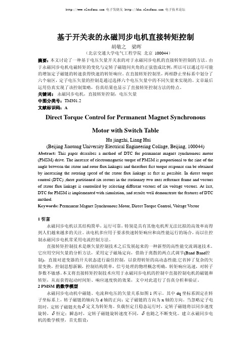
基于开关表的永磁同步电机直接转矩控制胡敬之梁晖(北京交通大学电气工程学院北京 100044)摘要:本文讨论了一种基于电压矢量开关表的对于永磁同步电机的直接转矩控制的方法。
由于永磁同步电机电磁转矩的变化与定转子磁链间夹角的正弦值成比例,所以可以通过尽可能的增加定子磁链的转速获得快速的转矩响应。
在直接转矩控制里,两相静止坐标系中划分了六个扇区,定子电压矢量的控制是通过选择六个电压矢量中的不同矢量来实现的。
文章最后运用仿真实现了该控制策略,仿真结果也显示了直接转矩控制方法的特点。
关键词:永磁同步电机,直接转矩控制,电压矢量中图分类号:TM301.2文献标识码:ADirect Torque Control for Permanent Magnet SynchronousMotor with Switch TableHu jingzhi, Liang Hui(Beijing Jiaotong University Electrical Engineering Collage, Beijing, 100044) Abstract: This paper describes a method of DTC for permanent magnet synchronous motor (PMSM) drive. The increase of electromagnetic torque of PMSM is proportional to the sine of the angle between the stator and rotor flux linkages and therefore fast torque response can be obtained by increasing the rotating speed of the stator flux linkage as fast as possible. In direct torque control (DTC) ,there partitioned six sectors in the stationary two-axes reference frame and vectors of stator flux linkage is controlled by selecting different vectors of six voltage vectors. At last, DTC for PMSM is implemented with simulation, and results well demonstrate the features of DTC method.Keywords: Permanent Magnet Synchronous Motor, Direct Torque Control, V oltage Vector1引言永磁同步电机以其结构简单,运行可靠,特别是具有其他电机所无法比拟的高效率而得到人们越来越多的关注。
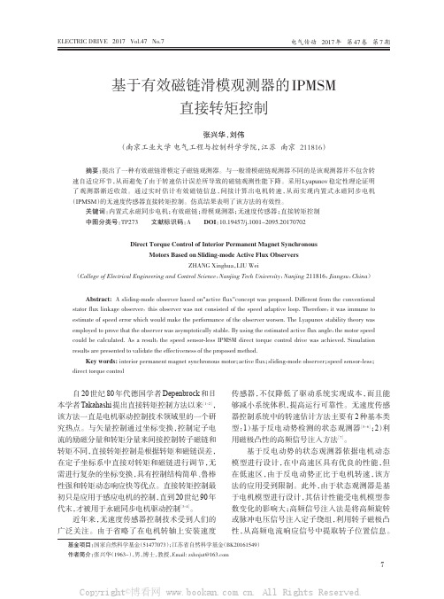
基于有效磁链滑模观测器的IPMSM直接转矩控制
江苏省自然科学基金(BK20161549)
作者简介:
张兴华(1963-),
男,
博士,教授,
Email: zxhnjut@
Copyright©博看网 . All Rights Reserved.
7
电气传动 2017 年 第 47 卷 第 7 期
有效磁链矢量 Ψa 和定子磁链矢量 Ψ s 、
转子磁链矢量 Ψ f 在静止坐标系 (α - β) 和转子磁
链旋转坐标系(d-q)中的关系如图 1 所示。
张兴华,等:基于有效磁链滑模观测器的 IPMSM 直接转矩控制
该方法在电机低速运行区甚至零速时有很好的
1.2
定义有效磁链(active flux)Ψa 为乘以 1.5 Pi qs
估计性能,其主要缺点是需额外增加高频信号源
和设计合适的滤波器,系统实现的硬件和软件结
构复杂。此外,注入的高频信号还会产生谐波转
于电机模型进行设计,其估计性能受电机模型参
代末,
才被用于永磁同步电机驱动控制
数变化的影响大;高频信号注入法是将高频旋转
。
[3-4]
近年来,无速度传感器控制技术受到人们的
广泛关注。由于省略了在电机转轴上安装速度
或脉冲电压信号注入定子绕组,利用转子磁极凸
性,从高频电流响应信号中提取转子位置信息。
基金项目:
speed sensor-less;
direct torque control
自 20 世纪 80 年代德国学者 Depenbrock 和日
本学者 Takahashi 提出直接转矩控制方法以来
,
[1-2]
传感器,不仅降低了驱动系统实现成本,而且能
永磁同步电机控制策略研究及仿真

永磁同步电机控制策略研究及仿真一、本文概述永磁同步电机(Permanent Magnet Synchronous Motor, PMSM)因其高效率、高功率密度、良好的控制性能等特点,在工业、交通、家电等领域得到了广泛应用。
随着电力电子技术和控制理论的发展,对PMSM的控制策略的研究也日益深入,旨在实现电机的高性能、高效率和可靠性。
本文主要针对永磁同步电机的控制策略进行研究和仿真分析。
本文首先对永磁同步电机的基本原理和控制方法进行了综述,包括电机结构、运行原理、数学模型等,为后续控制策略的研究奠定了基础。
详细讨论了几种常见的PMSM控制策略,如矢量控制(Vector Control)、直接转矩控制(Direct Torque Control, DTC)、模型预测控制(Model Predictive Control, MPC)等,分析了各种控制策略的优缺点及其适用场合。
接着,本文针对某特定应用背景,提出了一种改进的PMSM控制策略。
该策略在传统控制方法的基础上,引入了先进的控制算法和优化技术,旨在提高系统的动态性能、稳态性能和抗干扰能力。
本文还通过仿真实验,验证了所提控制策略的有效性和优越性。
二、永磁同步电机基本原理与特点永磁同步电机(Permanent Magnet Synchronous Motor, PMSM)是一种利用永磁体作为磁场源,实现电能与机械能相互转换的装置。
其基本原理基于电磁感应和磁场相互作用,通过控制定子电流产生的磁场与转子永磁体磁场之间的相互作用,实现电机的旋转运动。
高效率:由于使用永磁体作为磁场源,无需额外的励磁电流,因此电机在运行时具有较低的损耗和较高的效率。
高功率密度:永磁体的使用使得电机能够在较小的体积内实现较高的功率输出,适用于需要紧凑设计的应用场景。
良好的调速性能:通过控制定子电流的频率和相位,可以实现对PMSM的精确速度控制,满足宽范围调速的需求。
低维护成本:永磁体通常具有较高的磁能积和稳定性,使得电机在运行过程中无需频繁更换磁极,降低了维护成本。
永磁同步电机的直接转矩控制(英文)外文翻译

d, q: rotor rotation axis, d-axis direction is the rotor pole
direction
dc, qc: synchronous rotation axis, dc-axis direction is the
Te =
� P[(lf/sd (i,de
-If/,q (isde
{
If/Sd = LIdi'd III 'f'sq = Lsq.isq.
+ If/PM
(8)
Te =
It can be seen that:
� PIf/.,<r
x i"
(13)
(Notes: L,q = L,d = L, when it is non-salient pole motor)
. U,d = R.,Isd
Abstract-In order to improve the dynamic performance of
PMSM, a Direct Torque Control (DTC) scheme of Permanent Magnet Synchronous Motor (PMSM) is presented. Based on in depth analysis of PMSM mathematical model and the operation principle of DTC system, Matlab / Simulink is used to establish a simulation model of this system, and extensive research of simulation is conducted. A large number of simulation results show that the DTC System of PMSM has fast response and good dynamic performance, which verify correctness and feasibility of this system.
T型三电平逆变器馈电双三相PMSM直接转矩控制

T型三电平逆变器馈电双三相PMSM直接转矩控制王学庆;王政;程明【摘要】提出了一种T型三电平逆变器馈电双三相PMSM驱动系统直接转矩控制(DTC)策略.该系统既具有多相电机转矩脉动小、电流应力小和故障容错能力强的优点,也继承了T型三电平电机驱动谐波性能好、可靠性高的特点.该文所提出的基于双空间矢量调制(SVM)技术的直接转矩控制策略保留了DTC快速动态响应特性.与基于空间矢量解耦(VSD)的SVM技术相比,双SVM技术避免了复杂的矢量合成过程,并具有良好的谐波控制效果.所提出的控制策略还设计了谐波电流闭环控制器,能够有效抑制由绕组不对称、反电动势谐波、死区等非线性因素引起的低次谐波电流.通过实验验证了所提出的T型三电平逆变器馈电双三相PMSM驱动系统DTC 策略的有效性.%A direct torque control (DTC) strategy of T-type three-level inverter fed dual three-phase PMSM drives is proposed and studied in this paper. This system possesses the advantages of low torque pulsations, low current stress and strong fault tolerance from dual three-phase PMSM, while inheriting the characters of good harmonic performance and high reliability from T-type three-level inverter. The double space vector modulation (SVM) technology based direct torque control scheme proposed in this paper retains the fast dynamic performance of DTC. Compared to conventional vector space decomposition (VSD) based SVM technology, the proposed double SVMs technology can achieve good harmonic suppression effect, while avoiding complicated process of voltage vector synthesis. A closed-loop harmonic current controller is also designed in the proposed strategy, which can suppress the low orderharmonics caused by caused by motor asymmetry, EMF harmonic and dead-time effectively. The experimental result are given to verify the validity and feasibility of the DTC strategy of T-type three-level inverter fed dual three-phase PMSM drives.【期刊名称】《电工技术学报》【年(卷),期】2017(032)0z1【总页数】8页(P116-123)【关键词】双三相PMSM驱动;T型三电平逆变器;直接转矩控制;谐波抑制【作者】王学庆;王政;程明【作者单位】东南大学电气工程学院南京 210096;东南大学电气工程学院南京210096;东南大学电气工程学院南京 210096【正文语种】中文【中图分类】TM301.2近年来,随着大功率、高可靠性电机驱动系统需求的不断增加,多相电机已广泛应用于舰艇推进、电动汽车、轨道交通及航空航天等领域[1,2]。
电励磁同步电动机直接转矩控制理论研究及实践

电励磁同步电动机直接转矩控制理论研究及实践一、概括本文围绕电励磁同步电动机(Electrically Excited Synchronous Motorm,EESM)的直接转矩控制(Direct Torque Control,DTC)展开理论研究和实践探讨。
随着电力电子技术的发展,电励磁同步电动机因其高效、响应速度快等优点在诸多工业领域得到了广泛应用,特别是风力发电、电动汽车等领域。
EESM的直接转矩控制通过采样电动机定子电流和转速,并运用先进的控制算法实时精确地控制电动机的转矩和磁场,实现对电动机运行状态的精确跟踪与优化。
本论文首先对直接转矩控制的原理框架及数学模型进行了详尽阐述,构建了系统的数学模型,为实际应用奠定了理论基础。
本文详细分析了控制系统的稳定性与性能,重点研究了在非线性负载和扰动情况下该控制系统能否持续有效,以及如何提高系统整体性能。
论文还提出了一种改进的控制策略,该方法在传统直接转矩控制方法的基础上进行优化,提高了控制精度和响应速度。
通过仿真实验和实际现场实验验证了所提控制策略的正确性和有效性。
实验结果表明,采用改进后的控制方法能使电励磁同步电动机实现更高效、更稳定的运行,对于特定负载条件具有更好的适应性。
本文针对电励磁同步电动机直接转矩控制进行深入研究与实践,证明了该控制方法的有效性与实用性,并为进一步优化和完善控制策略提供了理论支持。
1.1 研究背景与意义随着电力电子技术、微处理器技术和控制理论的飞速发展,电气传动系统正经历着前所未有的变革。
在众多的电气传动方式中,电励磁同步电动机(Electrically Excited Synchronous Motors, EESM)因其独特的性能和广泛的应用场景,成为了研究的热点。
特别是直接转矩控制(Direct Torque Control, DTC)作为一种高效的电机控制策略,在EESM中展现出了巨大的应用潜力。
尽管直接转矩控制具有诸多优点,如响应速度快、精度高、算法简单等,但在实际应用中仍面临着诸多挑战。
永磁同步电机if电机控制算法
永磁同步电机(Permanent Magnet Synchronous Motor,PMSM)是一种常见的交流电机,其转子上装有永磁体,因此具有高效率、高功率密度和高转矩密度等优点。
在 PMSM 的控制中,常使用的算法是矢量控制(Vector Control)和直接转矩控制(Direct Torque Control,DTC)。
矢量控制是一种基于转子磁场定向的控制方法,它将电机的电流分解为励磁电流和转矩电流,并通过控制这两个电流分量来实现对电机转矩和速度的控制。
矢量控制算法需要对电机的参数进行精确测量和建模,因此对控制器的计算能力和传感器的精度要求较高。
直接转矩控制是一种直接控制电机转矩的方法,它通过测量电机的定子电压和电流,计算出电机的转矩和磁链,并通过控制定子电压和电流来实现对电机转矩的控制。
直接转矩控制算法不需要对电机的参数进行精确测量和建模,因此对控制器的计算能力和传感器的精度要求较低,但其控制精度和动态性能相对较差。
在实际应用中,矢量控制和直接转矩控制算法都有其优缺点,需要根据具体的应用场景和要求选择合适的算法。
此外,还有一些其他的控制算法,如模糊控制、神经网络控制等,也被应用于 PMSM 的控制中。
ALA+PM转子同步电机直接转矩控制探讨
研究与开发年第期3ALA+PM转子同步电机直接转矩控制探讨陈学珍(黄石理工学院电气与电子工程学院,湖北黄石435003)摘要该文比较了ALA+PM 转子同步电机和传统的PMSM 电机的转矩特性,前者随定子磁链的增大,转矩与负载角始终保持线性关系,不像后者需要约束条件。
直接转矩控制是ALA+PM 转子同步电机最好的控制方式,但定子磁链大于永磁磁链和小于永磁磁链,都会使定子电流增大,采用最大转矩/电流比(MTPA )方式给定定子磁链不会产生额外损耗。
关键词:ALA+PM ;直接转矩控制;定子磁链;MTPAAnalysis of Direct Torque Control for ALA+PM Rotor Synchronous MotorChen X uezhen(Department of Electrical &Electronic Engineering,Huangshi Institute of Technology,Huangshi,Hubei 435003)Abstr act This paper compares the torque characteristics of the ALA+PM rotor synchronous motor with one of the conventional PMSM,the former holds linearity relationship with the increase of stator flux linkage,the later needs restrict condition.The direct torque control(DTC)is the best control method for ALA+PM rotor synchronous motor,but the stator current can increase if the stator flux linkage is bigger or less than magnet flux linkage,It can ’t produce extra loss if MTPA is used.Key words :ALA+PM ;direct torque control ;stator flux linkage ;MTPA1引言直接转矩控制(DTC )是德国学者Depenbrock M 在20世纪80年代中期首次提出的一种异步电机变频调速技术[1]。
永磁同步电动机控制策略

永磁同步电动机控制策略综述1 引言近年来,随着电力电子技术、微电子技术、新型电机控制理论和稀土永磁材料的快速发展,永磁同步电动机得以迅速的推广应用。
永磁同步电动机具有体积小,损耗低,效率高等优点,在节约能源和环境保护日益受到重视的今天,对其研究就显得非常必要。
因此,这里对永磁同步电机的控制策略进行综述,并介绍了永磁同步电动机控制系统的各种控制策略发展方向。
2 永磁同步电动机的数学模型当永磁同步电动机的定子通入三相交流电时, 三相电流在定子绕组的电阻上产生电压降。
由三相交流电产生的旋转电枢磁动势及建立的电枢磁场,一方面切割定子绕组,并在定子绕组中产生感应电动势; 另一方面以电磁力拖动转子以同步转速旋转。
电枢电流还会产生仅与定子绕组相交链的定子绕组漏磁通, 并在定子绕组中产生感应漏电动势。
此外,转子永磁体产生的磁场也以同步转速切割定子绕组,从而产生空载电动势。
为了便于分析,在建立数学模型时,假设以下参数[2-3]:② 忽略电动机的铁心饱和;②不计电机中的涡流和磁滞损耗;③定子和转子磁动势所产生的磁场沿定子内圆按正弦分布,即忽略磁场中所有的空间谐波;④各相绕组对称,即各相绕组的匝数与电阻相同,各相轴线相互位移同样的电角度。
在分析同步电动机的数学模型时,常采用两相同步旋转(d ,q )坐标系和两相静止(α,β)坐标系。
图1 给出永磁同步电动机在(d ,q )旋转坐标系下的数学模型[4]。
(1) 定子电压方程为:d d d q f u p ri ψψω=+- (1) q q q d f u p ri ψψω=++ (2)式中:r 为定子绕组电阻;p 为微分算子,p=d/dt ;d i ,q i 为定子电流;d u ,q u 为定子电压;d ψ,q ψ分别为磁链在d ,q 轴上的分量;f ω为转子角速度(ω=f ω p n );p n 为电动机极对数。
(2)定子磁链方程为:d d d f L i ψψ=+ (3)q q q L i ψ= (4)式中:f ψ为转子磁链。
基于滑模观测器的PMSM变结构直接转矩控制

74
基于滑模观测器的 PMSM 变结构直接转矩控制
2020.№1
器,并且通过理论推导证明滑模观测器的可行性,再 通过二阶滑模的速度和转矩控制与 PI 控制进行对比, 从而分析出此系统具有良好稳定性与鲁棒性。
1 滑模观测器设计
本文采用内置式三相 PMSM( Ld Lq ),则 PMSM
在静止坐标系下的电压方程[8]:
u u
R
e
d dt
Ld
(Ld Lq
)
e (Ld
R
d dt
Lq Ld
)
i i
e e
(1)
式中,u 、u 为定子电压; i 、i 为定子电流; Ld 、Lq 为定子电感;e 为角速度;e 、e 为反电动
势。
反电动势模型:
e
=[(Ld
Lq
)(eid
. All RAibsgthratcst: IRn ethsisepravpeerd, a.new control system is designed, which consists of a sliding mode observer,
a second-order sliding mode speed controller based on Super-twisting algorithm, a flux linkage controller and a torque controller. The sliding mode observer (SMO) is designed by using the error between the given current and the actual current, and the rotor position is estimated by the arc tangent function. In this paper, the vector control model of three-phase permanent magnet synchronous motor is established by MATLAB software. Sensorless control and second-order sliding mode control model are introduced for simulation verification. The speed and torque waveforms of the motor are more stable, and the rotor position can be effectively observed. The results show that the control system is superior to the traditional control system. Key words: permanent magnet synchronous motor; sliding mode observer; torque control; second order sliding mode; arc tangent function
电机及控制技术论文集
电机及控制技术论文集本文基于SVM的直接转矩控制理论,以永磁同步电机数学模型为参考模型,以电机转速为可调参数建立参考模型,满足波波夫超稳定性定理构建合适的自适应率,实现了采用模型参考自适应法来进行永磁同步电机无速度传感器调速控制的方案。
在Matlab-Simulink软件环境下搭建系统的仿真图并进行仿真和分析,结果验证了该方案的可行性。
【关键词】SVM直接转矩控制无速度传感器 MRAS模型参考自适应永磁同步电机PMSM的体积小、噪声低、效率高、功率密度较大,在电力电子技术与现代控制理论迅速发展的大环境下,这些优点使PMSM渐渐得到了广泛的应用。
永磁同步电机的直接转矩控制DTC是在矢量控制发展日渐成熟之后兴起的另一种高性能交流调速技术。
由于拥有控制结构简洁、动态响应较快、对电机参数依赖较少等特点,直接转矩控制已成为学术界研究的热点。
在现代交流调速系统领域中,速度传感器由于存在降低系统可靠性,增加系统成本等问题,已经大大制约了交流传动系统的发展,所以采用无速度传感器的调速方案是当今国内外研究的趋势。
永磁同步电机无速度传感器的研究方法主要有基于磁链位置的估算法、基于反电动势法、滑膜观测器法、扩展卡尔曼滤波法、高频注入法、人工智能估算法、模型参考自适应法MRAS。
因为模型参考自适应法具有控制相对简单而且精度高的优点,所以本文将模型参考自适应法应用到永磁同步电机调速系统当中。
将永磁同步电机本身作为参考模型,将含有转子转速的模型作为可调模型,采用并联型结构进行速度辨识,两个模型的输出量物理意义相同。
利用可调和参考模型输出量所构成的误差,计算出合适的比例积分自适应率,并以此来调整可调模型的参数,满足Popov超稳定性定理,使系统逐渐稳定,最终使可调模型的状态能稳定、快速地逼近参考模型,即让误差值趋近于零,进而使转速估计值逐渐逼近实际值,实现转速的识别。
1 永磁同步电机数学模型建立dq坐标系下的数学模型,可以得到定子电压、电流均为直流的永磁同步电动机的电压方程式,利于分析永磁同步电动机控制系统的瞬态性能和稳态性能。
高性能永磁同步电机直接转矩控制
高性能永磁同步电机直接转矩控制一、概述随着能源危机和环境污染问题的日益严重,节能减排和提高能源利用效率已经成为全球性的研究热点。
在这个大背景下,永磁同步电机(PMSM)作为一种高效、节能的电机类型,受到了广泛的关注和应用。
直接转矩控制(DTC)作为一种先进的电机控制策略,因其具有控制结构简单、动态响应快、转矩脉动小等优点,在永磁同步电机的控制中得到了广泛的应用。
本文旨在探讨高性能永磁同步电机的直接转矩控制技术。
我们将对永磁同步电机和直接转矩控制的基本原理进行介绍,阐述其在电机控制中的优势和适用场景。
我们将重点分析高性能永磁同步电机直接转矩控制的实现方法,包括空间矢量脉宽调制(SVPWM)技术的应用、转矩和磁链的直接控制策略、以及转速和位置的精确检测等。
我们还将讨论在实际应用中可能遇到的挑战和问题,如参数变化、外部干扰等,并提出相应的解决方案和优化策略。
通过本文的研究,我们期望能够为高性能永磁同步电机直接转矩控制技术的发展提供有益的参考和借鉴,推动其在工业、交通、能源等领域的广泛应用,为实现节能减排和提高能源利用效率做出积极的贡献。
1. 永磁同步电机(PMSM)概述永磁同步电机(Permanent Magnet Synchronous Motor,简称PMSM)是一种利用永磁体产生磁场,通过电子换相实现电能与机械能转换的高效电动机。
它结合了传统直流电机和同步电机的优点,具有高功率密度、高效率和良好的调速性能。
PMSM的转子通常由永磁体构成,无需额外供电,从而减少了能量损失和复杂性。
定子则通过三相电流驱动,实现与转子磁场的同步旋转。
PMSM的控制策略对于其性能至关重要,其中直接转矩控制(Direct Torque Control,简称DTC)是一种广泛应用的先进控制方法。
DTC通过直接对电机转矩和磁链进行调控,能够迅速响应负载变化,实现高精度的速度控制和位置控制。
与传统的矢量控制相比,DTC具有结构简单、计算量小、动态响应快等优点,特别适用于高性能和快速响应的应用场景。
永磁同步电机滑模变结构鲁棒控制

永磁同步电机滑模变结构鲁棒控制崔家瑞;高江峰;张波;李擎【摘要】A sliding mode variable structure speed controller was proposed for surface permanent magnet synchronous motor in order to overcome the drawback of conventional PID speed controller,to effectively curb the state variables of overshoot problems, to speed up the convergence speed of the rotor, and to en-hance the anti-interference of the system.Unlike conventional PID speed controller, the controller associ-ated speed error with the quantity of system state.The load torque values is real-time controlled by the default upper and lower bounds sliding mode variable structure controller.It can replace the conventional PID controller with the applications to the permanent magnet synchronous motor vector control system. Simulation and experimental results show that sliding mode variable structure controller based on the up-per and lower bounds can effectively improve the static and dynamic characteristics and robustness of the system.%为了克服常规PID速度控制器的缺点,有效抑制状态变量的超调问题,加快转子的收敛速度,增强系统的抗干扰性,提出了一种用于表面式永磁同步电动机的上下界滑模变结构速度控制器。
《新能源汽车驱动电机与控制技术》的论文
《新能源汽车电机与控制技术》论文一、引言随着能源危机和环境污染的日益严重,新能源汽车作为一种节能、减排、低碳的交通工具,受到了国内外的广泛关注和重视。
新能源汽车,是指采用新型动力系统,完全或者主要依靠新型能源驱动的汽车,包括纯电动汽车、插电式混合动力汽车、增程式混合动力汽车和燃料电池汽车等12。
新能源汽车的发展不仅有利于保障能源安全,提高能源利用效率,改善环境质量,还有助于推动汽车产业的转型升级,增强国际竞争力。
新能源汽车的核心技术之一是驱动电机与控制技术,它决定了新能源汽车的动力性能、经济性能和安全性能。
驱动电机是新能源汽车的动力源,它将电能转化为机械能,驱动车轮运转。
控制技术是驱动电机的“大脑”,它根据车辆的工况和驾驶员的意图,对驱动电机进行精确的控制,实现最优的运行状态。
驱动电机与控制技术的优劣,直接影响了新能源汽车的性能、效率和寿命。
本文旨在对新能源汽车驱动电机与控制技术进行系统的分析和研究,主要内容和研究目的如下:(1)介绍新能源汽车驱动电机的类型和特点,分析各种类型的驱动电机的优缺点和适用范围,探讨新能源汽车驱动电机的发展趋势。
(2)介绍新能源汽车驱动电机控制器的基本原理和功能,介绍新能源汽车驱动电机的控制策略和方法,探讨新能源汽车驱动电机的控制技术的发展趋势。
(3)介绍国内外新能源汽车驱动电机与控制技术的典型应用案例,分析各种应用案例的技术特点和优势,探讨新能源汽车驱动电机与控制技术的应用前景和挑战。
本文的研究目的是为了深入了解新能源汽车驱动电机与控制技术的现状和发展,为新能源汽车的设计和优化提供参考和指导,为新能源汽车的推广和普及贡献力量。
二、新能源汽车驱动电机的类型和特点新能源汽车驱动电机是指将电能转化为机械能的装置,是新能源汽车的核心部件之一。
根据电机的工作原理和结构特点,新能源汽车驱动电机可以分为以下几种类型:直流电机:直流电机是指电枢和磁场之间的电流方向不随转子转动而改变的电机,主要有直流有刷电机和直流无刷电机两种。
两种IPMSM直接转矩控制比较研究
关键 词 :永磁 同步 电机 ;无 差拍 ;调节 器 ;直 接转 矩控 制
中图 分 类 号 :TM351
文 献标 识码 :A
文 章 编 3
Com parative Study of Direct Torque Control of IPM SM
1 引 言
IPMSM具 有 效 率 高 、功 率 密 度 大 、调 速 范 围 宽 等 优 点 ,广 泛 应 用 于 各 种 电机 驱 动 系 统 【1J。DTC和 矢 量 控 制 (FOC)是 用 于 高 性 能 永 磁 同 步 电机 驱 动 的两种 最 常 用 的方 法 。与 FOC方 法 相 比 ,DTC无 电 流 PI控 制 器 ,无 需 Park变 换 ,具 有 结 构 简单 ,动 态 响应 快和 鲁 棒 性 强等 优 点 。其 主要 缺 点 是转 矩 和磁 链 脉 动 较 大 ,开 关 频 率 不 固定 及 含 高 频 噪 声 等 _2_。 近 年 来 ,针 对 传 统 DTC 的 不 足 .许 多 学 者 进 行 了 大 量 研 究 工 ,但 均 存 在 不 足 。DB—DTC[ 】是 一 种 离 散 化 控 制 方 法 ,直 接 计 算 得 到 所 需 施 加 的 电压 矢 量 .理 论 上 可 在 一 个 控 制 周 期 内使 得 转 矩 和 磁 链 达 到 期 望 值 ,无 需 使 用 PI调 节 器 控 制 转 矩 和 磁 链 ,继 承 了传 统 DTC的 快 速 动 态 响 应 特 性 。 通 过
深入 分析 的基 础上 ,通过实 验分 别从 电机起 动 、稳态 性 能 、动 态性 能及 电流 谐波 等方 面对 这 两种 控制 策略 进行
比较 。 实 验 结 果 表 明 ,DB.DTC相 较 于 PI.DTC具 有 更 好 的 稳 态 和 动 态 性 能 ,且 有 更 低 的 相 电 流 谐 波 分 量 。
永磁同步电机直接转矩控制

永磁同步电机直接转矩控制摘要直接转矩控制是近年来应用比较广泛的一种控制策略。
它的优点包括控制原理直观明了,操作简单快捷,具有良好的转矩响应性。
而另一方面,永磁同步电机因为其运行的可靠性高,结构简单,所以在交流伺服电机中所处的地位越来越高。
基于这一发展趋势,本文重点研究了把直接转矩控制应用在永磁同步电机上的控制效果。
为了更好地分析永磁同步电机直接转矩控制,本文介绍了直接转矩控制的原理和它的优缺点,还有永磁同步电机的分类、结构及其在不同坐标系下的数学模型。
然后借助MATLAB中的Simulink功能,搭建永磁同步电机直接转矩控制系统的模型,对仿真结果进行分析归纳,最后得出结论。
结论表明,永磁同步电机直接转矩控制具有较好的转矩响应,基本能实现对永磁同步电机的快速可靠的控制,但是低速性能不佳,得不到快速的转矩响应。
这就确定了改善永磁同步电机直接转矩控制在低速时候的转矩响应将成为今后的发展趋势。
关键词: 直接转矩控制;永磁同步电机;仿真1AbstractDirect torque control (DTC) is used widely recently. It is intuitive and clear, simple and swift and has fast torque respond. on the other hand, permanent magnet synchronous machine (PMSM) become more and more important for its high reliability and simple structure. In this paper, we focused on the effect of the application of DTC to PMSM. In order to analyze PMSM DTC better, this paper precented both the advantage and the disavantage of DTC .What’s more,it also shownPMSM’s classification, structure, mathematical models in different coordinate system . Then I built model of PMSM DTC and smulated in the simulink environment. In the end I drew a conclusion by the result of simulation. The conclusion shown that PMSM DTC has quick torque respond to achieve rapid and reliable control. however, it has poor low-speed performance. Therefore, improving PMSM DTC low-speed performance will be the trend of improvement in the future.Keyword: PMSM , DTC , Simulation2目录摘要 ?ABSTRACT ?第一章绪论1.1 研究背景及研究意义 41.2 相关技术的发展情况 51.3 研究的主要内容 6第二章直接转矩控制概述2.1 电机控制策略分类 62.2 直接转矩控制原理 72.3 直接转矩控制的发展方向 82.4 本章小结 9 第三章永磁同步电机概述3.1 永磁同步电机的分类 93.2 永磁同步电机的结构 103.3 永磁同步电机的数学模型 123.4 本章小结 16 第四章永磁同步电机直接转矩控制4.1 永磁同步电机直接转矩控制原理 164.2 逆变器与开关表 174.3 定子磁链与电磁转矩的测定 194.4 本章小结 20 第五章永磁同步电机直接转矩控制仿真5.1 仿真软件 215.2 仿真模型 215.3 仿真结果分析 245.4 本章小结 26 第六章结论 26参考文献 283第一章绪论1.1 研究背景及研究意义自1834年德国的雅克比发明了第一台电机后,电机在人们日常的生产,生活中发挥着越来越大的作用。
永磁同步电机高效VF控制方法研究
永磁同步电机高效VF控制方法研究一、本文概述随着能源问题的日益严峻和环保意识的逐渐增强,高效节能的电机控制技术成为了当前研究的热点。
永磁同步电机(Permanent Magnet Synchronous Motor, PMSM)作为一种高性能的电机类型,因其高效率、高功率密度以及良好的调速性能等优点,在电动汽车、风力发电、工业机器人等领域得到了广泛应用。
研究永磁同步电机的高效控制方法具有重要的理论价值和实际意义。
本文旨在探讨永磁同步电机的高效VF(电压频率)控制方法。
通过对永磁同步电机的数学模型、控制策略以及优化算法等方面的深入研究,提出了一种新型的VF控制方法,旨在提高电机的运行效率和稳定性。
本文首先对永磁同步电机的基本原理和控制技术进行了概述,然后详细介绍了所提出的高效VF控制方法的具体实现过程,并通过仿真和实验验证了该方法的有效性和优越性。
本文的主要内容包括:永磁同步电机的基本数学模型和控制原理高效VF控制方法的设计和实现控制方法的仿真分析和实验研究以及控制方法的性能评估和优化。
通过对这些内容的深入研究和探讨,本文为永磁同步电机的高效控制提供了新的思路和方法,对于推动永磁同步电机技术的进一步发展和应用具有一定的指导意义。
二、永磁同步电机概述永磁同步电机(Permanent Magnet Synchronous Motor, PMSM)是近年来在电机控制领域受到广泛关注的一种高效、节能的电机类型。
其基本原理是利用永磁体产生的磁场与定子电流产生的磁场相互作用,实现电能到机械能的转换。
由于其具有高效率、高功率密度、高转矩惯量比以及低速大转矩等优点,PMSM在电动汽车、风力发电、工业自动化等多个领域得到了广泛应用。
PMSM的结构主要包括定子、转子和永磁体三部分。
定子通常由硅钢片叠压而成,用于产生旋转磁场转子则装有永磁体,这些永磁体产生的磁场与定子磁场相互作用,驱动电机旋转。
根据永磁体在转子上的安装位置,PMSM可分为表贴式、内置式和混合式等多种类型。
03 Analysis of Direct Torque Control in Permanent Magnet Synchronous Motor Drives
528IEEE TRANSACTIONS ON POWER ELECTRONICS,VOL.12,NO.3,MAY 1997Analysis of Direct Torque Control in Permanent Magnet Synchronous Motor DrivesL.Zhong,M.F.Rahman,Senior Member,IEEE,W.Y.Hu,and K.W.Lim,Senior Member,IEEEAbstract—This paper describes an investigation of direct torque control (DTC)for permanent magnet synchronous motor (PMSM)drives.It is mathematically proven that the increase of electromagnetic torque in a permanent magnet motor is proportional to the increase of the angle between the stator and rotor flux linkages,and,therefore,the fast torque response can be obtained by adjusting the rotating speed of the stator flux linkage as fast as possible.It is also shown that the zero voltage vectors should not be used,and stator flux linkage should be kept moving with respect to the rotor flux linkage all the time.The implementation of DTC in the permanent magnet motor is discussed,and it is found that for DTC using currently available digital signal processors (DSP’s),it is advantageous to have a motor with a high ratio of the rated stator flux linkage to stator voltage.The simulation results verify the proposed control and also show that the torque response under DTC is much faster than the one under current control.Index Terms—Direct torque control,permanent magnet syn-chronous motor,saliency,sensorless control,stator flux linkage.I.I NTRODUCTIONPERMANENT MAGNET synchronous motors (PMSM’s)are used in many applications that require rapid torque response and high-performance operation.The torque in PMSM’s is usually controlled by controlling the armature current based on the fact that the electromagnetic torque is proportional to the armature current.For high performance,the current control is normally executed in therotorPublisZHONG et al.:ANALYSIS OF DIRECT TORQUE CONTROL IN MOTOR DRIVES529Fig.1.The stator and rotorflux linkages in different reference frames.follows:(3)whereand(5)where(6)where represents the amplitude of the statorflux linkage.Substituting(5)and(6)for current into(2)gives-axis component of the stator current if the amplitudeof the statorflux linkage is constant.B.The Flux Linkage Equations inthe Reference FrameEquation(3)can be rewritten into matrix form asfollows:(12)or-axis isfixed at the statorflux linkage.Then,can be solved from the second equation of(13)if the amplitude of the statorflux linkage is keptconstantandThe maximum torque occurswhen530IEEE TRANSACTIONS ON POWER ELECTRONICS,VOL.12,NO.3,MAY1997 is considered to be a step change corresponding to achange of voltage vector.Then,the derivative of(15)becomesiswithin the range of This equation implies thatthe increase of torque is proportional to the increase of theanglecan be obtained by solvingfrom(12),with(18)Then,the torque equation is as follows:(19)Equation(19)consists of two terms.Thefirst is the excita-tion torque,which is produced by the permanent magnetflux,and the second term is the reluctance torque.For each statorflux linkage,there exists the maximum in this equation.It willnot be discussed how to control the amplitude of statorfluxlinkage and load angle to get maximum torque in this paper.However,it is necessary to discuss the relationship betweenthe amplitude of statorflux linkage and the derivative of thetorque.Figs.2–5show the torque-and,which implies that DTC cannot be applied in this case.Therefore,for a PMSM with pole saliency,the amplitude ofthe statorflux linkage should be changed,with the change ofactual torque even for constant torque operation.The derivative of torque in(20)is as shown in(21),withconstant statorflux and:(20)At(21)The condition for for positive isZHONG et al.:ANALYSIS OF DIRECT TORQUE CONTROL IN MOTOR DRIVES531Fig.5.Torque with respect to :j's j=2'f:III.C ONTROL OF S TATOR F LUX L INKAGE BY S ELECTING THE P ROPER S TATOR V OLTAGE V ECTORIn the previous section,it has been proven that the change of torque can be controlled by keeping the amplitude of the statorflux linkage constant and increasing the rotating speed of the statorflux linkage as fast as possible.It will be shown in this section that both the amplitude and rotating speed of the statorflux linkage can be controlled by selecting the proper stator voltage vectors.The primary voltagevector is defined by the followingequation:is connectedtoTherefore,there are six nonzero voltagevectors:apart from each other as in Fig.7.These eightvoltage vectors can be expressedas(24)whereisthe initial statorflux linkage at the instant of switching.Toselect the voltage vectors for controlling the amplitude of thestatorflux linkage,the voltage vector plane is divided intosix regions,as shown in Fig.8.In each region,two adjacentvoltage vectors,which give the minimum switching frequency,are selected to increase or decrease the amplitudeofand532IEEE TRANSACTIONS ON POWER ELECTRONICS,VOL.12,NO.3,MAY 1997TABLE IT HES WITCHING T ABLE FOR INVERTERFig.8.The control of the stator flux linkage.According to the torque (17)and (19),the electromag-netic torque can be controlled effectively by controlling the amplitude and rotational speedof For counter-clockwise operation,if the actual torque is smaller than the reference,the voltage vectors thatkeepincreases as fast as it can,and the actualtorque increases as well.Once the actual torque is greater than the reference,the voltage vectors thatkeepdecreases,and the torque decreases also.By selecting the voltage vectors in thisway,and,then the actual flux linkage is smaller than the reference value.The same is true for thetorque.and ,can be obtained fromthe measured three-phase currents,andvoltagesand are calculated from dc-link voltage since the voltage vectors determined by the switching table are known.The fluxlinkagesth sampling instant are calculated from the integration of the stator voltages asfollows:are the previous samples.The initial valuesofaheador behind the rotor flux linkage.The torque in (3)can be rewritten in the stationary reference frameasZHONG et al .:ANALYSIS OF DIRECT TORQUE CONTROL IN MOTOR DRIVES533Fig.10.Dynamic responses of a PMSM drive with DTC:T s =10 s :TABLE IIDQ A XES VOLTAGESThe reference torque is obtained from the output of the speed controller and is limited at a certain value,with respect to a given reference flux linkage,which guarantees the stator current not to exceed the limit value.For a PMSM with no pole saliency,the stator flux linkage can be kept at its rated value for constant torque operation,while for a PMSM with pole saliency,the reference flux linkage should increase with the actual torque for positive slope with respectto3Nmat3to 3Nmata nd s ,re s p e c t i v e l y .I t i sF i g .10t h a t t h e s t a t o r flu x l i n k a g e i s v a l u e q u i t e w e l l .T h e t r a j e c t o r y of534IEEE TRANSACTIONS ON POWER ELECTRONICS,VOL.12,NO.3,MAY1997Fig.11.Dynamic responses of a PMSM drive with DTC:T s=100s.s or less.For standard induction motors,this problem[40]does not arise because of the sufficiently large value of theflux linkage for the standard voltages and speeds of these motors.With DTC, the stator voltage vector changes every sampling time instead of every switching time as in a PWM current-controlled drive. According to(26),the change of statorflux linkage is equal to the product of dc-link voltage and sampling time.The bandwidth of theflux linkage hysteresis controller is normally set at5%of the rated value.Therefore,the sampling time should be very small for controlling theflux linkage properly, as shown in the simulation results of Fig.10for which the sampling interval is1010),which is2times of that of PMSM I in Table III and13times of that of PMSM II in Table IV.For applying the DTC in a PMSM drive,one PMSM,with the desirable ratio offlux linkage to dc-link voltage,has been built in which a standard induction motor stator is used,and the stator flux linkage is designed to have the same rated value as the induction motor.The data for this motor(PMSM III)is in Table V.TABLE IIID ATA OF PMSMITABLE IVD ATA OF PMSMIIC.The Comparison of the Torque ResponseBetween DTC and PWM Current ControlTo examine the performance of DTC,simulations on a PMSM with no saliency in Table VI(PMSM IV)under DTC and under PWM current control have been carried out.For DTC,the statorflux linkage is kept at its rated value,while for current control,is kept at zero.In both cases,the referenceZHONG et al.:ANALYSIS OF DIRECT TORQUE CONTROL IN MOTOR DRIVES535 TABLE VD ATA OF PMSM IIITABLE VID ATA OF PMSM IV(a)(b)Fig.12.Torque responses with DTC and current control:(a)torque responseunder DTC and(b)torque response under PWM current control in the rotorreference frame.torque is changed abruptly from3.0to536IEEE TRANSACTIONS ON POWER ELECTRONICS,VOL.12,NO.3,MAY1997W.Y.Hu received the Master’s degree from Jianxi University,Nanjing,China,in1966and the Mas-ter’s degree from Nanjing Aeronautical Institute, Nanjing,China,in1981.He worked at the Jinaxi Machine Tools Factory from1967to1977.He later joined the staff of the Nanjing Aeronautical Institute,undertaking re-search in the areas of induction motor drives and switched-mode power supplies.He is currently a Professor at the Nanjing University of Aeronautics andAstronautics.K.W.Lim(M’83–SM’92)received the B.Eng.and D.Phil.degrees from the University of Malaysia, Kuala Lumpur,Malaysia,and Oxford University, Oxford,U.K.,respectively.He is currently an Associate Professor at the University of New South Wales,Australia.His current research interests are in control of machines and multirate systems.Dr.Lim has been active in IEEE activities and is a Member of the Administrative Committee of the Industrial Electronics Society.。
永磁同步电动机超螺旋非奇异快速终端滑模转速控制
永磁同步电动机超螺旋非奇异快速终端滑模转速控制吉洪智; 赵朝会; 胡怡婷; 丁帆; 建照阳【期刊名称】《《上海电机学院学报》》【年(卷),期】2019(022)005【总页数】5页(P290-294)【关键词】永磁同步电动机; 非奇异快速终端滑模; 超螺旋; 直接转矩控制【作者】吉洪智; 赵朝会; 胡怡婷; 丁帆; 建照阳【作者单位】上海电机学院电气学院上海 201306【正文语种】中文【中图分类】TM351永磁同步电动机(Permanent Magnet Synch-ronous Motor, PMSM)的直接转矩控制(Direct Torque Control, DTC)技术首先由德国的Depen-brock和日本的Takahashi提出。
1997年,Zhong等[1]将这种技术应用于PMSM的控制。
DTC 结构简单、鲁棒性强,但是同时也存在转矩脉动大、开关频率不恒定等问题[2-3]。
为了解决该问题,国内外学者提出了许多改进技术[4-8]。
文献[4]详细介绍了应用空间矢量脉宽调制(Space Vector Pulse Width Modulation, SVPWM),DTC的转矩脉动大大减少,控制性能提高。
文献[7]介绍了采用预期电压矢量计算单元来代替传统DTC中的磁链以及转矩滞环比较器,可以有效地减小转矩脉动并对其进行优化。
文献[8]提出了一种结合DTC与空间矢量调制的方法,从而使得开关频率保持恒定并且降低了转矩脉动,但这种方法仍无法高精度地控制系统的稳态特性以及鲁棒性。
滑模变结构具有较高的稳态精度和较小的超调量,因此,这种方案具有很强的鲁棒性。
结合智能控制理论,学者们提出模糊滑模控制器、非奇异终端滑模控制以及高阶滑模的控制思想等,都不同程度地改善了系统鲁棒性、低速性能以及削弱抖振,但不同方法也有局限性[9-11]。
文献[12-14]介绍了滑模控制技术逐渐应用于电机控制及航空航天等领域。
文献[15]研究了一种全局非奇异快速终端滑模结构,提高了系统的稳定运行能力。
- 1、下载文档前请自行甄别文档内容的完整性,平台不提供额外的编辑、内容补充、找答案等附加服务。
- 2、"仅部分预览"的文档,不可在线预览部分如存在完整性等问题,可反馈申请退款(可完整预览的文档不适用该条件!)。
- 3、如文档侵犯您的权益,请联系客服反馈,我们会尽快为您处理(人工客服工作时间:9:00-18:30)。
A Direct Torque Control for a PMSMG. Mino-Aguilar, A. Michelle Domínguez, R. Maya, R. Alvarez, L. Cortez, G. Muñoz, F. Guerrero,S. Maya, A. M. Rodriguez, F. Portillo, H. Azucena.Benemérita Universidad Autónoma de Puebla, Mexico.gerardo.mino@ece.buap.mxAbstractFor a long time, permanent magnet synchronous motors (PMSM) were only applied in some particular fields, e.g. for servo drives. However, in recent years PMSM gained increasing importance in novel domains like automotive hybrid drive trains [1]. For Mexico, this boom represents a valuable opportunity for universities and research institutions, so that together with Mexican industry of the Electric Vehicle (EV) forming partnerships that result in an infrastructure that will enable the country to develop its own technology in terms of EV. This paper presents a competent and not complex direct torque controller (DTC) for PMSM drives.1. Introduction.The study of the electric machine and control has been toughened by two major universal problems: pollution (water, ground, and the atmosphere) and overpopulation. This last one has created in part extremely high demands of power and personal means of travel, and this has inevitably resulted in the first [2].An increase of electric motors efficiency, which consumes more than half the electricity generated, can result in an important electrical energy savings [3]. In recent years the trend has changed from not only improving the design characteristics of the electric machine by developing better ways to control them, but also using digital systems, power electronics and advanced techniques of control [4].In particular, the three-phase induction motors (IM) are commonly used in industry, because not only do they have a simple design, but also they are reliable and inexpensive. The permanent magnet synchronous motors (PMSM) are increasing in popularity due to their high efficiency and power density. Many motor applications require a precise control of both speed and torque, which is possible by using frequency converters between the power lines and the motor. Another way to save electricity is by adjusting the motor speed [5]. Nowadays it can be said that the trend of use variable speed drives has increased significantly, especially where the torque and speed are to be varied to control the speed, position, flow and torque.Among the various methods used to control motors, the direct torque control (DTC) technique has an important place. This technique involves the respective control of the torque and flux linkage by selecting a proper voltage vector.The essential idea of DTC is to pick an appropriate voltage vector using a predefined switching table. This is achieved by calculating the instantaneous torque and flux from the stator machine variables. The torque and flux are controlled directly and independently through the selection of optimum inverter switching states and limiting the errors of the flux and torque by hysteresis controllers. DTC’s operation is illustrated in Fig. 1.The DTC has advantages for implementing a driver of low-cost and high performance, because the only parameter of the engine involved is the stator resistance. The well-known DTC is implemented in Matlab/Simulink to observe the performance of the PMSM at different speeds and loading conditions. Blocks were implemented for the models such as the MSIP, the DTC, the park transformation and the inverter.2. Direct Torque Control (DTC).Direct torque control, is a vector control method, Figure 1. Diagram of a typical DTC−PMSM drive.which incorporates the control voltage converter inside the speed control algorithm. The optimal switching sequence of the inverter transistors (VSI) is directly based on the state of flux and electromagnetic torque of the PMSM. The necessary calculations are performed using the equations from the model of the PMSM as well as currents and voltages in the stator terminals [6].The general DTC premises are [8]-The estimated instantaneous flux vector should remain close to its reference.- The estimated torque should remain close to its reference.-The dynamic engine behavior can be studied from sudden changes that may occur both in the reference speed of the rotor or from the torque reference value. These assumptions involve four major tasksa)Determine the appropriate values of the references.b)Calculate the actual values of the flux vector andelectromagnetic torque.c)Make an appropriate interpretation of the errorsbetween estimated values and their references.d)Manipulate the state of the inverter to reduce thespeed error.Fig. 1 shows the DTC for a PMSM block diagram. One can see, that once one has the estimated and reference instantaneous values of electromagnetic torque and stator flux, we proceed to calculate the error between them; these error are used as input for the hysteresis controllers. The output levels achieved in this stage of the control are input signals to the block that is responsible for finding the right vector to get rid of the error rate. This procedure is made for each sampling instant for driving the PMSM to the desired speed value.3. Flux and torque reference.The hysteresis controller output is generated after the estimated flux is compared with its reference. However, this reference value is obtained based on the electromagnetic torque reference [7]. The stator flux module can be expressed asІψsІ= ( ψsD 2 + ψsQ2 ) 1/2 (1) where ψs is the stator flux vector, ψsD and ψsQ are the sD and sQ axes stator fluxes given byψsD = L d i sD + ψm , (2)ψsQ = L q i sQ . (3)L d and L q are the direct and quadrature inductances, i sD and i sQ are the sD and sQ stator currents and ψm is the flux from the permanent magnets.Using (1) - (3) the magnitude of stator flux can be expressed asІψsІ= [ ( L d i sD + ψm) 2 + ( L sQ i sQ ) 2 ] 1/2 , (4) and considering that the electromagnetic torque is given by (5) where P is the number of pole pairst e = 3 / 2 P( ψm i sQ + ( L d – L q) i sD i sQ ) , (5)in which, the maximum torque per unit of current is obtained by considering i sD = 0, then (5) is ast e = 3 / 2 Pψm i sQ.(6) Thus the current produced by the torque isi sQ = 2t e / 3Pψm.(7)Substituting (7) in (4) the function required to obtain the reference flux isІψsref І = [ ( L d i sD + ψm) 2 + L q2( 2t eref / 3Pψm ) 2 ] 1/2. (8)The reference torque is generated through the PI controller for speed.4. Estimated flux.Using the position of the rotor and the stator currents, the stator flux estimation is given by the following equation [7] where θr is the rotor angle, Ls and is are inductance matrix and current vector of the statorψs =ІψsІe jθr = ψsD +jψsD = L s i s +ІψmІe jθr, (9) 5. Estimated torque.Using the estimated fluxes and the measured stator currents transformed into the stationary reference frame the electromagnetic torque can be calculated using [7]t e = ( 3/2 ) P( ψsD i sD – ψsQ i sQ ). (13)6. Estimated angle.It is possible to estimate the stator flux angle ρs through its stationary reference frame components so the angle is calculated usingρs = tan-1( ψsQ /ψsD). (14)7. Hysteresis controllers.When the estimated value of the variable is far from its reference, it will be necessary to use a suitable voltage vector to modify it so it stays within certain limits around the reference. Hysteresis controllers aim to maintain the torque and flux errors within upper and lower limits allowed, so that when evaluating within these limits an output level is obtained to know the status of the variable.8. Switching table.The main objective of the switching table is the get the fastest torque response. The switching table presented by Takahashi and Noguchi (Table 3) takes into account the sector (α(1),α(2),…,α(6)) in which the stator flux vector is located in stationary reference frame (sD, sQ) and the digital output levels of the flux and torque hysteresis controllers (d ψs, dTe).Fig. 2 shows that each sector covering 60 electrical degrees by the regions α(1),α(2),…,α(6), where the sector 1 covers from –30° up to 30°, sector 2 from 30° to 90° and so on until 330° is reached. The plane is defined by the axes sD and sQ where sD is at zero degrees [7].As shown in Fig. 3, the determination of the sector is made with res pect to the angle ρs at which the flux vector ψs is located.Once located the sector and having the state of the signals d ψs, dTe which indicate whether the variable should be increased or decreased, the voltage vector applied at each instant is to be determinate. Fig. 3 shows a situation in which the flux vector ψs is in the sector α(2) at the lower limit of hysteresis band. If a flux increment is required, it is necessary to apply a voltage vector to increase the radius of this circle, the vectors that achieve this goal are 1, 2 and 3 [9].Table 3. Commutation table by Takahashi andNoguchiFigure 2. Sectors distribution to locate fluxposition.Figure 3. Example of positioning the flux vectorin sector 2.To vary the torque Te an action is required on the load angle (δ), that is, a vector which causes a displacement on ψs must be chosen. In the case of Fig. 3, vectors 3 and 4 will increase the torque, 5 and 6 will decrease it. Accordingly, the application of different vectors will change the ψs behavior in different ways (size and position).9. Simulation.The dynamic model equations of the PMSM and all procedures involved in the DTC can be implemented thru simulation.The PMSM is described using SIMULINK blocks. The initial position and the load are considered as inputs to system and the engine’s mathematical relationships aredefined through subsystems.Changes between reference frames are performed through Park transformations.To control the PMSM, is made thru the implementation of the DTC. Some of the blocks include the estimators of flux, torque and position, the selection of the sector in which the stator flux vector is positioned, hysteresis controllers, the PI controller for the speed, as well as others.Fig. 4 shows the DTC implementation. First current and rotor angle are sampled. Once sampled an axis transformation of the currents takes place, those currents are used to calculate the stator flux components which together with the currents are used to obtain the estimated flux, torque and angle. These estimations of flux and torque are entered along with their corresponding references as input signals to the blocks called Subsystem and Subsystem1, which are the hysteresis controllers of the DTC. The output signals of these controllers together with the sector selection block output go through the switching table where the optimal vector shall be obtained, thereby achieving necessary changes in the motor flux and torque to reach the reference speed.To find the sector in which the stator flux is located, the block called “Look-Up Table” is used, which evaluates the input with respect to certain key points previously established. The “Look-Up Table” simply delivers the output data that indicates the matching sector.10. Results.Fig. 5 shows the actual motor speed compared with its reference previously set to a constant value of 1500 rpm. Fig. 6a shows the flux behavior and Fig. 6b illustrates the torque behavior, it can be seen how both remain close to their reference values.Figure 4. SIMULINK block diagram of the DTC.Figure 5. Constant reference speed at 1500 rpm.Figure 6. Comparison of estimated valuesagainst their references.With constant reference speed and changes in load, in Fig 7 can be seen that when load changes there is a minor repercussion in speed. At the moment when the load increases, the rotor speed tends to drop, this can clearly be seen at the 1.5 seconds, where the load was increased from 1 Nm to 3 Nm, then there is an opposite effect when load goes down, the speed increases for a few moments to re-establish its reference.Fig. 8 shows the estimated torque as it tries to follow its reference formed around the load.In Fig. 9a a variable speed is introduced, the motor speed follows its reference and there are only minor variations when load is increased or decreased. Fig 9b illustrates the load applied to the motor. In Fig. 9c can be seen how the electromagnetic torque has to compensate both speed and load increases, so that for a few seconds the reference torque has more noticeable variation, this can be seen at 0.5, 2 and 2.5 sec when changes in speed are introduced.Figure 7. (a) Constant reference speed at 1000rpm, (b) load variations.Figure 8. Behavior of the electromagnetic torquedue to changes in load.Figure 9. (a) Variable reference speed, (b) load variations, (c) electromagnetic torque behavior. 11. Conclusions.Although several techniques of control exist, the main objective of this paper was the implementation of DTC for a PMSM, which is based on the control of the motor’s torque and flux separately. Both torque and flux estimators were been implemented, stator flux angle was also calculated. From different reference speeds has been obtained necessary reference values for both electromagnetic components. In addition to this, also, through the blocks Look-up Table and Direct Look-up table, were derived both the area in which the flux vector is located and the optimal switching vector applied to the engine.The performance of this technique was tested by simulations driven in Matlab/Simulink. The simulation results show desirable behavior. It can be seen that the control meets the demands of the system quickly, what can be translated as a friendly speed control. It was illustrated how the stator flux and the motor torque can be held under control through voltage space vectors.It has been demonstrated that both instantaneous stator flux vector, and electromagnetic torque produced in a PMSM, can be estimated directly from the currents and voltages sensed in terminals of the motor.12. References.[1] Ouassaid, M., Cherkaoui, M., Nejmi, A. and Maarou, M. “Nonlinear Torque Control for PMSM: A Lyapunov Technique Approach,” Proceedings of World Academy of Science, Engineering and Technology, vol.6, pp. 118-121, June 2005. [2] Kosow, I., Control de máquinas eléctricas, Mexico: Reverte, 1977.[3] Viqueira Landa, J., “La generación y transmisión de energía eléctrica en México,” unpublished.[4] Ponce Cruz, P., and Sampé López, J., Máquinas eléctricas y técnicas modernas de control, D.F., Mexico: Alfaomega, 2008.[5] de Almeida, A. T., Ferreira, F., and Both, D., “Technical and economical considerations in the application of variable-speed drives with electric motor systems,” IEEE Trans. o n Industry Applications, vol. 41, pp. 188–199, Jan-Feb 2005.[6] Eguilaz Moreno, J., ”Aportaciones a la optimizacion de energia en accionamientos electricos de motores de induccion mediante logica difusa,” unpublished.[7] Vas, Peter, Sensorless Vector and Direct Torque Control, New York : Oxford University Press, 1998.[8] Nava Segura, A., Hernández Arámburo, C. and Mino Aguilar, G., “Induction Motor Direct Stator Flux and Torque Vector Control,” Proceedings of the IASTED International Conference Power and Energy Systems, 1999.[9] LLor, Ana M., “Control Directo de Par a Frecuencia de Modulacion Constante de Motores Sincronos de Imanes Permanentes,” unpublished.[10] Nava Segura, A., Hernández Arámburo, C. and Mino Aguilar, G., “Instantaneous Space Vector Model for Direct Flux and Torque Control of an Inverter Controlled Induction Motor,”Proceedings of the IASTED International Conference Power and Energy Systems, 1999.[11] Bose Bimal, K. Power Electronics and Motor Drives; Advances and Trends, Elsevier Inc., 2006.[12] Bose Bimal, K. Power Electronics and Variable Frequency Drives, TECHNOLOGY AND APPLICATIONS, Nueva York : Standard Publishers Distributors, 1997.。