LC-155A2H1RM中文资料
LC1F150产品数据手册说明书

LC1F150i s c l a ime r : T h i s d o c u m e n t a t i o n i s n o t i n t e n d e d a s a s u b s t i t u t ef o r a n d i s n o t t o b e u s e d f o r d e t e r m i n i ng s u i t a b i l i t y o r r e l i a b i l i t y o f th e s e p r o d u c t s f o r s p e ci f i c u s e r a p p l i c a t i o n sProduct data sheetCharacteristicsLC1F150TeSys F contactor - 3P(3 NO) - AC-3 - <= 440 V 150 A - without coilMainRange TeSys Product nameTeSys F Product or component type Contactor Device short name LC1F Contactor application Motor control Resistive load Utilisation categoryAC-4AC-1AC-3Poles description 3P Pole contact composition 3 NO[Ue] rated operational voltage <= 1000 V AC 50/60 Hz <= 460 V DC[Ie] rated operational current 250 A (<= 40 °C) at <= 440 V AC AC-1150 A (<= 55 °C) at <= 440 V AC AC-3Motor power kW65 kW at 1000 V AC 50/60 Hz AC-375 kW at 380...400 V AC 50/60 Hz AC-390 kW at 500 V AC 50/60 Hz AC-3100 kW at 660...690 V AC 50/60 Hz AC-322 kW at 400 V AC 50/60 Hz AC-480 kW at 415 V AC 50/60 Hz AC-380 kW at 440 V AC 50/60 Hz AC-340 kW at 220...240 V AC 50/60 Hz AC-3Complementary[Uimp] rated impulse withstand voltage 8 kV Overvoltage categoryIII[Ith] conventional free air thermal current250 A at <= 40 °CIrms rated making capacity 1500 A AC conforming to IEC 60947-4-1Rated breaking capacity1200 A conforming to IEC 60947-4-1[Icw] rated short-time withstand current1200 A <= 40 °C 10 s700 A <= 40 °C 30 s600 A <= 40 °C 1 min450 A <= 40 °C 3 min350 A <= 40 °C 10 minAssociated fuse rating160 A aM at <= 440 V250 A gG at <= 440 VAverage impedance0.35 mOhm at 50 Hz - Ith 250 A[Ui] rated insulation voltage1000 V conforming to IEC 60947-4-11500 V conforming to VDE 0110 group CPower dissipation per pole22 W AC-18 W AC-3Mounting support PlateStandards JIS C8201-4-1IEC 60947-4-1EN 60947-4-1EN 60947-1IEC 60947-1Product certifications LROS (Lloyds register of shipping)CSAULDNVABSBVRMRoSRINACBConnections - terminals Power circuit : connector 1 cable(s) 120 mm²Power circuit : lugs-ring terminals 1 cable(s) 120 mm²Power circuit : bolted connectionPower circuit : bar 2 x (25 x 3 mm)Tightening torque Power circuit : 18 N.mEnvironmentIP degree of protection IP2x front face with shrouds (ordered separately) conforming to IEC 60529IP2x front face with shrouds (ordered separately) conforming to VDE 0106 Protective treatment THAmbient air temperature for operation-5...55 °CAmbient air temperature for storage-60...80 °C-40...70 °CPermissible ambient air temperaturearound the deviceOperating altitude3000 m without derating in temperatureMechanical robustness Vibrations contactor closed 6 Gn, 5...300 HzShocks contactor open 9 Gn for 11 msVibrations contactor open 2 Gn, 5...300 HzShocks contactor closed 15 Gn for 11 msHeight170 mmWidth163.5 mmDepth171 mmProduct weight 3.83 kgOffer SustainabilitySustainable offer status Green Premium productRoHS (date code: YYWW)Compliant - since 0843 - Schneider Electric declaration of conformitySchneider Electric declaration of conformityREACh Reference not containing SVHC above the thresholdReference not containing SVHC above the thresholdProduct environmental profile AvailableProduct environmentalProduct end of life instructions AvailableEnd of life manual Contractual warrantyWarranty period18 monthsLC1F150。
朔明商标 ICR18650 锂二极电池规格表说明书

Library Sort Product Specifications VER IILibrary Name Cylindrical Li‐ion Rechargeable Battery Date 2004/4/30Cylindrical Li-ion batterySpecificationType: ICR18650Prepared/Date Auditing/Date Approved/Date Genxiao Li Peng kun Gao Dragon LvLibrary Sort Product Specifications VER II Library Name Cylindrical Li‐ion Rechargeable Battery Date 2004/4/301.PerformanceTest item Test conditions Requirements(1)Outside Appearance Visual check No abnormal stain,Deformation nor damage(2) Standard test conditions Measurements are carried out at 20±5℃and relative humidity of 65±20% without other specified condition.Accuracy of voltmeters and ammeters used in test is equal to or better than the grade 0.5.(3) Standard charge Battery is charged continuously at the constant current of 0.5 I t end at voltage of 4.2V, then charge at the constant voltage of 4.2V until the end current of 20mA after Pre-discharge at the constant current of 0.2 I t until the end voltage of 2.75V/cell(4) Fast charge Charge shall be conducted continuously at theconstant current of 1500mA until the end voltage of4.2V, then charge at the constant voltage of 4.2Vuntil the end current of 20mA after Pre-dischargementioned in Item (2).(5)Open-circuitvoltage (OCV)≥3.75V(6)Rated Capacity Discharge duration of the charged battery specifiedin Item (3) shall be measured at 0.2 I t mA until theend voltage of 2.75V/cell, after rest for 0.25 hour.If the discharge duration does not reach thespecified value, the test may be repeated up to threetimes in total.Rated capacity:≥100%C5mAh(7)Capacity high-rate discharge Discharge duration of the charged battery specifiedin Item (3) shall be measured at 1500mA until the endvoltage of 2.75V/cell, after rest for 0.25 hour. Ifthe discharge duration does not reach the specifiedvalue, the test may be repeated up to three times intotal.Discharge capacity:≥90%C5mAh(8) Cycle Life (20℃) Carry out cycles (1500mA CC/CV(4.2V), discharge atthe constant current of 1500mA after rest for 0.25hour) at20± 2℃. The test end until the dischargecapacity <60%C5mAh≥300 cyclesLibrary Sort Product Specifications VER II Library Name Cylindrical Li‐ion Rechargeable Battery Date 2004/4/30(9)Low temperature discharge 1)charge shall be conducted at Item (3);2)Thebattery shall be stored under -20℃±2℃ for 16h~24h;3)Discharge shall be conducted at the constantcurrent of 0.2I t mA until the end voltage of2.75V/cell;Discharge capacity:≥60%C5mAh2 Mechanical testTest Item Test Conditions Requirements(1)Vibration Test Vibrate test sample for 90minutes each at roomtemperature after rated charge.Amplitude: 0.38mm(10-30Hz);0.19mm(30-55Hz)Frequency: 10-55Hz(1oct/min)Direction: X, YThen measure resistance, voltage of battery andcheck outside appearance.No rupture, fire, smoke,Nor critical damage≧90% C5mAh(2) Drop Test Drop 100% charged test sample from 1m above ontoconcrete board with more than 5cm thickness two timeseach for every direction at room temperature.Then measure rated capacity and checks outsideappearance. No rupture, fire, smoke, Nor critical damage≧90% C5mAh3 Safety evaluationTest Item Test Conditions Requirements(1) Hot Oven Test The charged battery is to be heated in a gravityconvection or circulating air oven. The temperatureof the oven is to be raised at a rate of 5±2℃ perminute. The oven is to remain for 30 minutes at 150±2℃ before the test is discontinued.No fire, Nor explosion(2)Short Circuit Test After fast charge at 20±2℃, Connect batteryterminals with electric wire ( electric resistance:50mΩor less ). And stop the test when thetemperature of battery is 10℃lower than peaktemperature.No fire, Nor explosion(3) Overcharge Test After discharged at 1 I t mA and end at 2.75V, thebattery shall be charged at 3 I t mA current with avoltage limit of 4.6V.No fire, Nor explosion(4)Dip test The charged battery shall be dipped in water for 24hin an ambient temperature of 20℃±5℃.No fire, Nor explosionLibrary Sort Product Specifications VER IILibrary Name Cylindrical Li‐ion Rechargeable Battery Date 2004/4/304 Charge State of Battery before shipmentTo be determined.(Recommendation Approx. 3.75 – 3.85V 30% charge)5 Duration of guarantee the productWe can keep on the quality in six month.6 Handling precautions on Lithium Ion Rechargeable BatteryTo assure product safety, describe the following precautions in the instruction manual of the equipment.! Danger-When charging the battery, use dedicated chargers and follow the specified conditions.-Use the battery only in the specified equipment.-Do not connect battery directly to an electric outlet or cigarette lighter charger.-Do not heat or throw battery into a fire.-Do not use, leave battery close to fire or inside of a car where temperature may be above 60℃. Also do not charge / discharge in such conditions.-Do not immerse, throw, and wet battery in water/ seawater.-Do not put batteries in your pockets or a bag together with metal objects such as necklaces.Hairpins, coins, or screws. Do not store batteries with such objects.-Do not short circuit the (+) and (-) terminals with other metals.-Do not place battery in a device with the (+) and (-) in the wrong way around.-Do not pierce battery with a sharp object such as a needle.-Do not hit with a hammer, step on or throw or drop to cause strong shock.-Do not disassemble or modify the battery.-Do not solder a battery directly.-Do not use a battery with serious scar or deformation.! Warning-Do not put battery into a microware oven, dryer, or high-pressure container.-Do not use battery with dry cells and other primary batteries, or batteries of a different package, type, or brand.-Stop charging the battery if charging is not completed within the specified time.-Stop using the battery if abnormal heat, odor, discoloration, deformation or abnormal condition is detectedDuring use, charge, or storage.-Keep away from fire immediately when leakage or foul odor is detected.-If liquid leaks onto your skin or clothes, wash well with fresh water immediately.If liquid leaking from the battery gets into your eyes, do not rub your eyes. Wash them well with clean water and go to see a doctor immediately.! Caution-Store batteries out of reach of children so that they are not accidentally swallowed.Library Sort Product Specifications VER IILibrary Name Cylindrical Li‐ion Rechargeable Battery Date 2004/4/30-If younger children use the battery, their guardians should explain the proper handling. -Before using the battery, be sure to read the user’s manual and cautions on handling thoroughly.-Thoroughly read the user’s manual for the charger before charging the battery.-For information on installing and removing from equipment, thoroughly read the user’s manual for the specific equipment.-Batteries have life cycles. If the time that the battery powers equipment becomes much shorter than usual, the battery life is at an end. Replace the battery with a new same one.-Remove a battery whose life cycle has expired from equipment immediately.-When the battery is thrown away, be sure it is non-conducting by applying vinyl tape to the (+) and (-) terminals.-When not using battery for an extended period, remove it from the equipment and store ina place with low humidity and low temperature.-While the battery pack is charged, used and stored, keep it away from objects or materials with static electric charges.-If the terminals of the battery become dirty, wipe with a dry clothe before using the battery. -The battery can be used within the following temperature ranges. Do not exceed these ranges.Charge temperature range : 0℃ to 45℃Discharge temperature range : -20℃ to 60℃(When using equipment)。
LCP日本宝理Laperos全系列型号特性及命名规则

6
东莞市棋丰塑胶原料有限公司
罗龙
宝理LCP使用领域
LCP被广泛应用于平板电脑、智能手机等不断小型化的最新IT设备中的超小 型精密连接器。
9
东莞市棋丰塑胶原料有限公司
罗龙
公司及个人介绍
东莞市棋丰塑胶原料有限公司,创立于2010年,位于广东省东莞市常平镇。主要代理或分销进口塑 胶原料,生产定制高性能改性塑料。 棋丰塑胶与全球超过45家著名化学制造商保持着良好的伙伴关系,集成国内外厂商的先进产品和技 术,为各行业客户量身定制产品配套方案,我们致力于将自身打造成为化工产业链上的第一服务平台。 棋丰塑胶是高性能工程塑胶领域的科技创新企业。我们与客户、合作伙伴携手合作共同提高国内工程 塑胶改性技术。棋丰塑胶先后与国内外多家科研机构合作,高薪聘请国内外工程塑胶原料领域著名专 家及教授担当技术顾问,积极研发新产品,目前已经积累了1000多份材料改性配方。
LCP日本宝理Laperos
全系列型号、特性及命名规则
编写:罗龙
1
东莞市棋丰塑胶原料有限公司
罗龙
目录
宝理LCP全系列型号特性 宝理LCP命名规则 宝理LCP主要特性 宝理LCP使用领域 宝理LCP加工工艺
2
东莞市棋丰塑胶原料有限公司
罗龙
宝理LCP全系列型号特性
品牌
Laperos Laperos Laperos Laperos Laperos Laperos Laperos Laperos Laperos Laperos Laperos Laperos Laperos Laperos Laperos Laperos Laperos Laperos Laperos Laperos Laperos Laperos Laperos Laperos Laperos Laperos Laperos Laperos Laperos Laperos Laperos Laperos
施耐德HVX系列中压真空断路器.
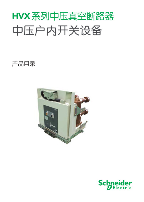
HVX 系列中压真空断路器中压户内开关设备产品目录施耐德电气善用其效 尽享其能施耐德电气在中国1987年,施耐德电气在天津成立第一家合资工厂梅兰日兰,将断路器技术带到中国,取代传统保险丝,使得中国用户用电安全性大为增强,并为断路器标准的建立作出了卓越的贡献。
90年代初,施耐德电气旗下品牌奇胜率先将开关面板带入中国,结束了中国使用灯绳开关的时代。
施耐德电气的高额投资有力地支持了中国的经济建设,并为中国客户提供了先进的产品支持和完善的技术服务,中低压电器、变频器、接触器等工业产品大量运用在中国国内的经济建设中,促进了中国工业化的进程。
目前,施耐德电气在中国共建立了77个办事处,26家工厂,6个物流中心,1个研修学院,3个研发中心,1个实验室,700多家分销商和遍布全国的销售网络。
施耐德电气中国目前员工数近22,000人。
通过与合作伙伴以及大量经销商的合作,施耐德电气为中国创造了成千上万个就业机会。
施耐德电气 能效管理平台全球能效管理专家施耐德电气为世界100多个国家提供整体解决方案,其中在能源与基础设施、工业过程控制、楼宇自动化和数据中心与网络等市场处于世界领先地位,在住宅应用领域也拥有强大的市场能力。
致力于为客户提供安全、可靠、高效的能源,施耐德电气2010年的销售额为196亿欧元, 拥有超过110,000名员工。
施耐德电气助您——善用其效,尽享其能!凭借其对五大市场的的深刻了解、对集团客户的悉心关爱,以及在能效管理领域的丰富经验,施耐德电气从一个优秀的产品和设备供应商逐步成长为整体解决方案提供商。
今年,施耐德电气首次集成其在建筑楼宇、IT 、安防、电力及工业过程和设备等五大领域的专业技术和经验,将其高质量的产品和解决方案融合在一个统一的架构下,通过标准的界面为各行业客户提供一个开放、透明、节能、高效的能效管理平台,为企业客户节省高达30%的投资成本和运营成本。
HVX 中压真空断路器系列目录HVX 真空断路器 (2)基本特征 (2)标准 (2)环境和运行条件 (2)设计 (3)机构 (3)极柱 (4)型号组成及面板操作 (5)手车式结构示意图 (5)试验及电寿命 (6)试验 (6)真空灭弧室允许操作次数与开断电流的关系 (6)应用 (6)二次装置 (7)二次装置电压等级 (9)选型表 (10)HVX 12kV 真空断路器 (10)HVX 24kV 真空断路器 (12)HVX 40.5kV 真空断路器 (14)二次电路图 (16)HVX 12kV/24kV 真空断路器手车式带防跳继电器 (16)HVX 12kV/24kV 真空断路器手车式无防跳继电器 (17)HVX 12kV/24kV 真空断路器固定式带防跳继电器 (18)HVX 12kV/24kV 真空断路器固定式无防跳继电器 (19)HVX 12kV/24kV 真空断路器电动手车式带防跳继电器 (20)HVX 12kV/24kV 真空断路器电动手车式无防跳继电器 (21)HVX 40.5kV 真空断路器手车式带防跳继电器 (22)HVX 40.5kV 真空断路器手车式无防跳继电器 (23)HVX 40.5kV 真空断路器固定式带防跳继电器 (24)HVX 40.5kV 真空断路器固定式无防跳继电器 (25)外型尺寸图 (26)HVX 12kV 真空断路器固定式 (26)HVX 12kV 真空断路器手车式 (27)HVX 12kV 真空断路器固定式 (28)HVX 12kV 真空断路器手车式 (29)HVX 24kV 真空断路器手车式 (30)HVX 40.5kV 真空断路器固定式 (32)HVX 40.5kV 真空断路器中置手车式 (33)HVX 40.5kV 真空断路器落地手车式 (1200mm柜宽) (34)HVX 40.5kV 真空断路器落地手车式 (1400mm柜宽) (35)订货表 (36)HVX 12kV/24kV 真空断路器订货表 (36)HVX 40.5kV 真空断路器订货表 (37)HVX 中压真空断路器系列HVX 系列真空断路器是施耐德电气在中压领域百年的技术结晶,适用于主流的空气绝缘开关设备,广泛地应用于石油化工、配电系统、交通运输、工矿企业等领域。
A155 运行说明书

C300-16.67/0.981/538/538型300MW中间再热抽汽凝汽式汽轮机说明书概述及运行说明目录1 主要技术规范2 概述3汽轮机控制整定值4汽轮机冷却蒸汽系统的检查5 监测仪表5.1 汽缸膨胀5.2 转子位置5.3 差胀5.4 转子偏心5.5 振动5.6 相位角5.7 累加的阀门位置5.8 零转速5.9 转速6 测定蒸汽及金属温度的热电偶7 调节级叶片的运行建议7.1 引言7.2 运行建议7.3 汽轮机阀门控制方式的变换8 蒸汽参数的允许变化范围8.1 进出压力8.2 再热压力8.3 进口温度8.4 再热温度8.5 高——中压合缸9 汽轮机蒸汽品质10 运行限制及注意事项10.1 一般注意事项10.2 汽轮机偏周波运行10.3 汽封用蒸汽10.4 低压排汽及排汽缸喷水装置10.5 进水10.6 疏水阀10.7 监测仪表10.8 轴承及油系统10.9 备用电源10.10 其它11 汽轮机进水11.1 运行11.2 维护12 启动和负荷变化的建议12.1 目的12.2 汽轮机转子的热应力12.3 汽轮机启动程序12.4 负荷变化的建议12.5 转子疲劳寿命损耗的确定13 调节阀的管理(节流——喷嘴)13.1 冲转与最小负荷13.2 负荷变化13.3 停机13.4 调节方式的转换14 抽汽阀的管理15 初步检查运行15.1 检查步骤15.2 预防措施及规则16 进汽前的启动程序17 冷态启动——用蒸汽冲转17.1 供蒸汽前的状态17.2 用蒸汽冲转17.3 在暖机期间避开低压汽轮机叶片的共振转速17.4 冷态启动转子加热(中速暖机)过程17.5 从主汽阀控制切换到调节汽阀控制17.6 同步和初始负荷17.7 超速遮断试验18 热态启动——用蒸汽冲转18.1 供汽前的状态18.2 用蒸汽冲转18.3 在暖机期间避开低压汽轮机叶片的共振转速18.4 从主汽阀控制切换到调节汽阀控制18.5 同步和初始负荷19 负荷变化20 停机程序20.1 正常停机20.2 应急停机20.3 在停机期间的盘车运行21 给水加热器运行21.1 投用21.2 解列21.3 应急运行21.4 多级加热器22 定期的性能试验22.1 每周一次的试验22.2 每月一次的试验22.3 每半年一次的试验23 遥控自动运行模式23.1 自动同步器23.2 遥控23.3 汽轮机自动控制(ATC)24 汽轮机手动操作运行模式25 运行曲线及图表25.1 汽轮机暖机转速的建议25.2 冷态启动暖机规程25.3 热态启动和建议——冲转和带最低负荷25.4 启动蒸汽参数25.5 空负荷和低负荷运行导则25.6 负荷变化的建议(定压运行)25.7 负荷变化的建议(变压运行)25.8 不同增减负荷率的循环指数25.9 汽封蒸汽温度的建议25.10 典型高压汽轮机的冷却时间25.11 汽轮机偏周波运行26 限制值、预防措施和试验26.1 监测仪表报警和脱扣整定值26.2 轴承温度和压力26.3 蒸汽参数——温度、压力和湿度26.4 凝汽器真空(汽轮机背压)26.5 进水26.6 控制系统试验26.7 总体1 主要技术规范产品编号:A1552 概述本装置是单轴、双缸、双排汽、中间再热、抽汽凝汽式汽轮机、具有运行效率高和可靠性大的特点。
武汉力兴(火炬)电源有限公 锂锰柱式电池 产品规格书
锂 锰 柱 式 电 池产品规格书电池型号:CR17450编 制: 日期: 审 核: 日期: 确 认:日期:客户确认:___________ 日期:____________供货商: 武汉力兴(火炬)电源有限公司地 址: 中国.武汉.关东科技园7号电 话: 86-27-87561426 87561322 传 真: 86-27-87801891武汉力兴(火炬)电源有限公司编 号:Q/LX.S.C.08.006-2008版本号: A/0CR17450版本号: A/01.目的1.1对武汉力兴(火炬)电源有限公司出品的锂电池的产品规格、测试方法进行规范,避免因测试条件、方法的不同引起偏差。
1.2指导客户正确选择和使用我公司电池。
2. 产品类别和产品型号表1类别型号锂锰柱式电池CR174503.产品基本特性表2序号项目特性℃ mA恒流连续放电至终止电压2.0V)1 标称容量 2000mAh(23±3102 标称电压 3V3 工作温度范围 -20~+60℃4 年自放电率≤2%mA5 最大脉冲电流 30006 最大连续放电电流 1500mA7 结构及成分二氧化锰正极、锂负极、有机电液、隔膜及钢外壳等8 重量参考值25 g4.外形示意图及尺寸4.1外形示意图如下表3最大值( mm ) Ф2最大值( mm )5 CR17450 17.0 6.CR17450版本号: A/06.2.2 当恒流放电容量不低于标准值且低于标准值80%的电池数为0时,判定电池容量合格。
6.2.3 当平均放电容量低于标准值或低于标准值80%的电池数大于0时,重新取6只样品进行试验,若平均放电容量不低于标准值且低于标准值80%的电池数为0时,判定电池容量合格。
6.2.4 若第二次试验中平均放电容量低于标准值或低于标准值80%的电池数大于0时,判定电池容量不合格,不再进行第三次试验。
6.3 试验条件 6.3.1 电池状态电池应为下机后三个月以内的电池,下机时间以电池上的标识为准。
多层陶瓷电容器

容量与温度关系图 1
20 COG
0
X7R -20
容量变化(%)
-40
Z5U
-60
-100
-50
0
50
温度(℃)
100
150
福州欧中电子有限公司
2
Tel:(0591)87871172/182 Fax:87809119
Email: eurocn@
福州欧中电子有限公司
1
Tel:(0591)87871172/182 Fax:87809119
Email: eurocn@
多层陶瓷电容器介质电特性
多层陶瓷电容器基本原理
电极
介质
±10% P ±15% R +22-56% U +22-82% V
介质分类
陶瓷电容一般是以其温度系数作为主要分类。 Class I - 一类陶瓷(超稳定)EIA 称之为 COG 或 NPO。工作温度范围 -55℃~+125℃,容量变化不 超过±30ppm/℃。电容温度变化时,容值很稳定, 被称作具有温度补偿功能,适用于要求容值在温度 变化范围内稳定和高 Q 值的线路以及各种谐振线 路。
端头
t
A
电容量的公式为: C = NKA/t
式中: C = 电容量 N = 电极层数 K = 介质常数(K 值) A = 相对电极覆盖面积 t = 电极间距(介质厚度)
采用多层技术生产陶瓷电容便可以实现大容 量小体积的需求,增大 N(增加层数)便可增大容 量。反观单层的电容,N 始终是 1,若再要提高容 量,必定采用高 K 值(降低稳定性能)、增加 A(增 大体积)或降低 t(降低耐电压能力)。
LCD 逆变器应用- FB9 系列..………………………………....................................……...........................31
NXAIR M 高压短路保护开关面板及 HV HRC 重罐断电缸说明书
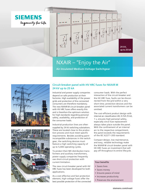
Industrial and power supply companies depend on safe production at their factories. High availability of the power grids and protection of the connected consumers are therefore mandatory. The new NXAIR M circuit-breaker panel with HV HRC fuses offers exactly this and is therefore the optimum solution for high standards regarding personal safety, availability, and protection of the consumer loads.Industrial production lines are often supplied by 24 kV switching substations. These are located close to the produc-tion process and must meet specific requirements. Besides avoiding paint-incompatible substances in the switch-gear, the switching devices must feature a high switching capacity of up to 5,000 operating cycles.To protect their MV distribution trans-formers and auxiliary transformers, power supply companies frequently use short-circuit protection with current limitation.The new circuit-breaker panel with HV HRC fuses has been developed for both applications.As a cost-effective and fast protection element, high-voltage fuses offer the best possible protection of the connected24 kV, up to 25 kAconsumer loads. With the perfect interaction of the circuit-breaker and the HV HRC fuse, faults can be discon-nected from the grid within a very short time; protection devices and the associated current transformers can be omitted.The cost-efficient product design with internal arc classification IAC A FLR 25 kA, 1 s, ensures high personal safety, especially since fuse replacement always takes place outside the panel. With the confinement of an internal arc to the respective compartment, the panel exceeds the requirements of the IEC 62271-200 pact design, low maintenance, and easy, reliable technology make the NXAIR M circuit-breaker panel with HV HRC fuses an investment that will pay off throughout its entire lifecycle.Circuit-breaker panel with HV HRC fuses for NXAIR M 24 kV up to 25 kA/nxairNXAIR – “Enjoy the Air“Air-Insulated Medium-Voltage SwitchgearTechnical features• Factory-assembled, type-testedswitchgear according to IEC 62271-200• Loss of service continuity category LSC 2B • Partition class PM (metallic partition)• Switchgear with internal arc classification according to IAC A FLR for an arc duration of 1 s• Confinement of an internal arc to the respective compartment (pressure- resistant partitions), exceeding the requirements of the standard• Fused circuit-switchers tested according to IEC 62271-107• All switching operations can only be performed with closed high-voltage door • Unambiguous position indicators and control elements as standard on the high-voltage door• Use of maintenance-free vacuum circuit-breakers• Fuse replacement always possible outside the panel and without tools • Transformer protection up to max. 2000 kVA resp. 1600 kVA with 1.4-fold overloadTechnical data for NXAIR M circuit-breaker panel with HV HRC fuses© 2018 Siemens. Subject to changes and errors. The infor- mation given in this document only contains general descrip-tions and/or performancefeatures which may not always specifically reflect thosedescribed, or which may undergo modification in the course of further development of the products. The requested perfor-mance features are binding only when they are expressly agreed upon in the concluded contract. NXAIR is a registered trademark of Siemens AG. Any unautho-rized use is prohibited. All other designations in this document may represent trademarks whose use by third parties for their own purposes may violate the proprietary rights of the owner.Siemens AGEnergy ManagementMedium Voltage & Systems Postfach 324091050 Erlangen, Germany /nxairArticle-No. EMMS-B10125-00-7600 | Printed in Germany | Dispo 30400 | PU 184/004445 PB 08.18 1.0Basic panel design。
飞鸟1555和1550C电阻性电抗试验仪商品说明书
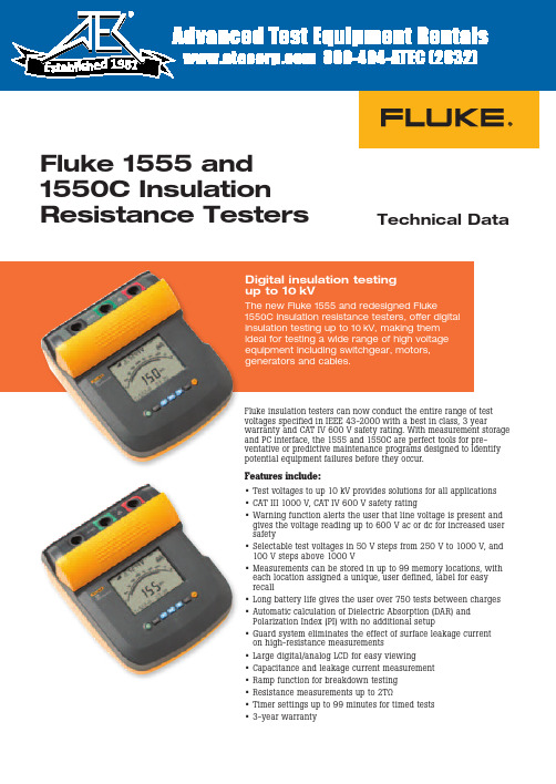
Technical DataFluke 1555 and 1550C Insulation Resistance TestersFluke insulation testers can now conduct the entire range of test voltages specified in IEEE 43-2000 with a best in class, 3 yearwarranty and CAT IV 600 V safety rating. With measurement storage and PC interface, the 1555 and 1550C are perfect tools for pre-ventative or predictive maintenance programs designed to identify potential equipment failures before they occur.Features include:• Test voltages to up 10 kV provides solutions for all applications • CAT III 1000 V, CAT IV 600 V safety rating• Warning function alerts the user that line voltage is present andgives the voltage reading up to 600 V ac or dc for increased user safety• Selectable test voltages in 50 V steps from 250 V to 1000 V, and 100 V steps above 1000 V• Measurements can be stored in up to 99 memory locations, with each location assigned a unique, user defined, label for easy recall• Long battery life gives the user over 750 tests between charges • Automatic calculation of Dielectric Absorption (DAR) and Polarization Index (PI) with no additional setup• Guard system eliminates the effect of surface leakage current on high-resistance measurements• Large digital/analog LCD for easy viewing• Capacitance and leakage current measurement • Ramp function for breakdown testing • Resistance measurements up to 2TΩ• Timer settings up to 99 minutes for timed tests • 3-year warrantyDigital insulation testing up to 10 kVThe new Fluke 1555 and redesigned Fluke1550C insulation resistance testers, offer digital insulation testing up to 10 kV, making them ideal for testing a wide range of high voltage equipment including switchgear, motors, generators and cables.19812 Fluke Corporation Fluke 1555 and 1550C Insulation Resistance TestersFluke CorporationPO Box 9090, Everett, WA USA 98206Fluke Europe B.V.PO Box 1186, 5602 BD Eindhoven, The NetherlandsFor more information call:In the U.S.A. (800) 443-5853 or Fax (425) 446-5116In Europe/M-East/Africa +31 (0) 40 2675 200 or Fax +31 (0) 40 2675 222In Canada (800)-36-FLUKE or Fax (905) 890-6866From other countries +1 (425) 446-5500 or Fax +1 (425) 446-5116Web access: ©2005-2010 Fluke Corporation.Specifications subject to change without notice. Printed in U.S.A. 10/2010 1629685G D-EN-N Modification of this document is not permitted without written permission from Fluke Corporation.Fluke. Keeping your world up and running.Ordering information1550C 5 kV Insulation Tester 1555 10 kV Insulation Tester 1550C/Kit 5 kV Insulation Tester Kit 1555/Kit 10 kV Insulation Tester KitOptional accessoriesTL1550EXT 25 foot extendedtest lead setIncluded accessoriesTest Cables with Alligator Clips (red, black, green)Infrared adapter with interface cable FlukeView Forms Basic CD-ROM AC Power CordSoft Carrying Case (base models only)English ManualUsers Manual on CD-ROM Quick Reference CardSoftware License Agreement Registration CardFlukeView Forms Installation Guide USB-IR Cable Installation Guide IP67 Hard Case (kit only)Certificate of Calibration (kit only)Ruggedized Alligator Clips (kit and 1555 only)Software specification sFluke ViewForms basic softwarerequires a PC running Windows 2000, Windows XP and Windows Vista.SpecificationsElectrical specificationsThe tester’s accuracy is specified for one year after calibration at operating temperatures of 0 °C to 35 °C. For operating temperatures outside the range (-20 °C to 0 °C and 35 °C to 50 °C), add ± .25 % per °C, except on the 20 % bands add ± 1 % per °C.Insulation resistance measurementTest voltage (dc)RangeAccuracy (± reading)250 V< 200 kΩ200 kΩ to 5 GΩ5 GΩ to 50 GΩ> 50 GΩunspecified 5 %20 %unspecified 500 V< 200 kΩ200 kΩ to 10 GΩ10 GΩ to 100 GΩ> 100 GΩunspecified 5 %20 %unspecified 1000 V< 200 kΩ200 kΩ to 20 GΩ20 GΩ to 200 GΩ> 200 GΩunspecified 5 %20 %unspecified 2500 V< 200 kΩ200 kΩ to 50 GΩ50 GΩ to 500 GΩ> 500 GΩunspecified 5 %20 %unspecified 5000 V< 200 kΩ200 kΩ to 100 GΩ100 GΩ to 1 TΩ> 1 TΩunspecified 5 %20 %unspecified 10000 V (1555 Only)< 200 kΩ200 kΩ to 200 GΩ200 GΩ to 2 TΩ> 2 TΩunspecified 5 %20 %unspecifiedBar graph range0 to 1 TΩInsulation test voltage accuracy -0 %, +10 % at 1 mA load current Induced ac mains current rejection 2 mA maximum Charging rate for capacitive load5 seconds per μF Discharge rate for capacitive load 1.5 s/μFRangeAccuracyLeakage current measurement1 nA to2 mA ± (5 % + 2 nA)Capacitance measurement 0.01 uF to 15.00 μF ± (15 % rdg + 0.03 μF)TimerRangeResolution0 to 99 minutesSetting: 1 minute Indication: 1 second Live circuit warningWarning rangeVoltage accuracy 30 V to 660 V ac/dc, 50/60 Hz± (15 % + 2 V)General specifications。
睿英电气RM系列数字式电动机综合保护装置
RM030
RM050
RM100
RM150
RM200
型号
工作电压 频率 三相
功率因数保护
谐波测量保护
温度测量保护
功率保护
欠/过电流保护
保护功能
缺相保护 不平衡保护
逆相保护
堵转保护
短路保护
接地保护
失速保护
通讯MODBUS 4~20mA输出
产品概述,功能与特点·······················································································2 型号选择················································································································3 安装尺寸················································································································5 接线端子,指示灯说明·······················································································6 接线图····················································································································6 技术指标················································································································7
人民电器 HH15(QSA)系列隔离开关熔断器组 产品说明书
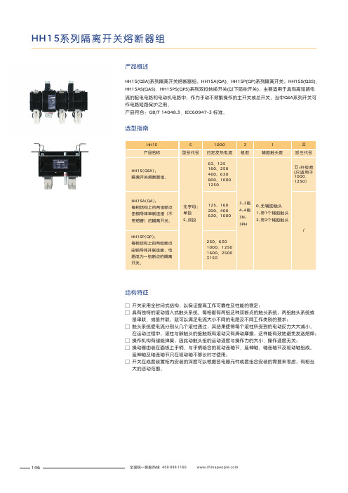
HH15系列隔离开关熔断器组HH15(QSA)系列隔离开关熔断器组,HH15A(QA)、HH15P(QP)系列隔离开关,HH15S(QSS)、HH15AS(QAS)、HH15PS(QPS)系列双投转换开关以下简称开关,主要适用于具有高短路电流的配电电路和电动机电路中,作为手动不频繁操作的主开关或总开关。
当中QSA 系列开关可作电路短路保护之用。
GB/T 14048.3IEC60947-3 ()产品符合:、标准。
产品概述选型指南结构特征□ □ 具有独特的滚动插入式触头系统。
每相都有两组这种双断点的触头系统,两组触头系统或 是串联、或是并联,就可以满足电流大小不同的电路及不同工作类别的要求;□ 触头系统使电流分别从几个滚柱通过,其结果使得每个滚柱所受到的电动反力大大减小。
在运动过程中,滚柱与静触头的接触既有滚动又有滑动摩擦,这样能有效地避免发送熔焊;□ 操作机构有储能弹簧,因此动触头组的运动速度与操作力的大小、操作速度无关;□ 操动器由装在面板上手柄、与手柄啮合的驱动连轴节、延伸轴、轴连轴节及驱动轴组成。
延伸轴及轴连轴节只在驱动轴不够长时才使用;□ 开关在成套装置柜内安装的深度可以根据各电器元件成套组合安装的需要来考虑,有相当 大的活动范围。
开关采用全封闭式结构,以保证提高工作可靠性及性能的稳定;146HH15(QSA)-63、125AHH15(QSA)系列隔离开关熔断器组主要技术参数HH15(QSA)系列隔离开关熔断器组外形及安装尺寸147HH15(QSA)系列隔离开关熔断器组外形及安装尺寸HH15(QSA)-160、250、400AHH15(QSA)-630A148HH15系列隔离开关熔断器组HH15(QSA)-800A149150HH15系列隔离开关熔断器组HH15A(QA)系列隔离开关外形及安装尺寸HH15A(QA)系列隔离开关主要技术参数151152HH15系列隔离开关熔断器组HH15P(QP)系列隔离开关外形及安装尺寸HH15P(QP)系列隔离开关主要技术参数153154HH15系列隔离开关熔断器组HH15a 1b 5(HH15)c 1d 1□ □ 我公司所提供的开关价格是不含熔断器的,若用户在订货时提出,我公司可配套提供熔断器,但一般不装在开关本体上。
GRM1555C1H1R0CA01D中文资料
物料编号:GRM1555C1H1R0CA01D详细参数_易容网
MLCC即是多层陶瓷电容片式,是电子信息产品不可或缺的基本组件之一。
我国MLCC的生产起步在80年代初,行业早期主要是在外资企业的带动下发展起来的,近年来国内企业在技术上实现突破,行业国产化成效显著,并推动了MLCC产量迅速增长。
目前,MLCC的应用领域已从手机、电脑、电视机等消费电子领域,逐步拓展到新能源发电、新能源汽车、节能灯具、轨道交通、直流输变电、三网融合、高清电视、机顶盒、手机电视等多个行业。
对于这个悄悄活跃在人们生活中的元件你又知道多少呢.
本次易容网为大家推荐比较常用的MLCC村田 | Murata品牌的料号GRM1555C1H1R0CA01D的相关参数
易容网是深圳市易容信息技术有限公司独自研发的全球最大的MLCC搜索采购服务网站,2014年创立于深圳市南山区,全国首家电子元器件行业电容元件的搜索引擎及o2o商务服务平台。
易容网()现已建成全球最大的MLCC电容搜索引擎数据库,包含全球25家电容生产厂商超过28万组MLCC产品数据,用户可根据行业应用、物料编号、规格参数等信息快速的找到所有相关的MLCC电容数据。
易容网在搜索服务的前提下还提供村田、TDK、国巨、太阳诱电、风华高科等常见品牌产品的o2o商务服务,让企业客户实现询价、报价、在线订单、出库、实时物流、签收、账期服务等在线一站式商务服务体验。
耐克森中压产品简介 2012

损耗效应:
• 本身电阻损耗 • 感应损耗(如:护套涡流、环流) • 集肤效应损耗
H Iind屏蔽层
导体 内半导电屏蔽
主绝缘层 外半导电屏蔽
d D
E(r)
功能:
• 均化绝缘内部电场分布 • 绝缘隔热层
r
14
HV
绝缘
作用:
特性:
• 具有半导电性, 表面平滑 • 遇水时可膨胀
17
金属护层
功能:
• 电场控制 (电气屏蔽) • 释放静电荷, 短路电流通道 • 径向防水功能 (金属防水层) • 机械防护
轴向粘接平滑铜护套 无缝挤出铅护套 焊接皱纹铜护套 无缝挤出皱纹铝护套 18
外护套层
功能:
• 绝缘:将金属护层与地绝缘 • 防腐蚀 • 机械防护 (敷设时)
接头本体铜屏蔽网 7 sleeve protection of joint body
接头本体保护管 8 Injected resin
注射的树脂 9 Armoured tape 加强带
三芯中间接头
三芯中间接头特点
特点: • 预制程度高,安装比同类产品更加简便。 • 有超过20年树脂浇注防水技术,使三芯电缆的防水性能得到充分保
> 自动控制
建筑业 Building > 民用住宅、
办公大楼和 工业大楼
2
• 1个全球研发中心 • 9 个技术中心 • 450 名研究员、工程师和技术人员 • 420项注册专利 • 平均每周研发2种新产品
先进科技的领导地位:
• 高速数据传输 • 绝缘材料 • 塑料光纤 • 超导体 • 安全防火电缆
注射树脂
接口 电流
危险化学品特性表汇总(常用)
目录2.1 类易燃气体表-氢气的理化性质及危险特性 (1)表-甲烷[压缩的]的理化性质及危险特性 (2)表-天然气的理化性质及危险特性 (3)表-液化甲烷的理化性质及危险特性 (4)表-液化天然气的理化性质及危险特性 (5)表-乙烷的理化性质及危险特性 (6)表-液化乙烷的理化性质及危险特性 (7)表-丙烷的理化性质及危险特性 (8)表-正丁烷的理化性质及危险特性 (9)表-环丙烷的理化性质及危险特性 (10)表-液化乙烯的理化性质及危险特性 (11)表-丙烯的理化性质及危险特性 (12)表-异丁烯的理化性质及危险特性 (13)表-丁二烯的理化性质及危险特性 (14)表-乙炔的理化性质及危险特性 (15)表-1,1-二氟乙烷的理化性质及危险特性 (16)表-1,1,1-三氟乙烷的理化性质及危险特性 (17)表-氟乙烯[抑制了的]的理化性质及危险特性 (18)表-二氟氯乙烷的理化性质及危险特性 (19)表-环氧乙烷的理化性质及危险特性 (20)表-(二)甲醚的理化性质及危险特性 (21)表-甲乙醚的理化性质及危险特性 (22)表-乙烯基甲醚的理化性质及危险特性 (23)表-三甲胺的理化性质及危险特性 (24)表-乙胺的理化性质及危险特性 (25)表-液化石油气的理化性质及危险特性 (26)2.2 类不燃气体表-氧气的理化性质及危险特性 (27)表-液氧的理化性质及危险特性 (28)表-空气[压缩的]的理化性质及危险特性 (29)表-氮气的理化性质及危险特性 (30)表-液氮的理化性质及危险特性 (31)表-氦气的理化性质及危险特性 (32)表-液氦的理化性质及危险特性 (33)表-氖气的理化性质及危险特性 (34)表-液氖的理化性质及危险特性 (35)表-氩气的理化性质及危险特性 (36)表-液氩的理化性质及危险特性 (37)表-一氧化二氮的理化性质及危险特性 (38)表-二氧化碳的理化性质及危险特性 (39)表-二氧化碳[液化的]的理化性质及危险特性 (40)表-六氟化硫的理化性质及危险特性 (41)表-氯化氢的理化性质及危险特性 (42)表-稀有气体混合物的理化性质及危险特性 (43)表-稀有气体和氧气混合物的理化性质及危险特性 (44)表-稀有气体和氮气混合物的理化性质及危险特性 (45)表-二氧化碳和氧气混合物的理化性质及危险特性 (46)表-二氧化碳和一氧化二氮混合物的理化性质及危险特性 (47)表-二氧化碳和环氧乙烷混合物的理化性质及危险特性 (48)表-三氟甲烷的理化性质及危险特性表 (49)表-四氟甲烷的理化性质及危险特性 (50)表-氯二氟甲烷的理化性质及危险特性 (51)表-氯三氟甲烷的理化性质及危险特性 (52)表-氯四氟乙烷的理化性质及危险特性 (53)表-二氯二氟甲烷的理化性质及危险特性 (54)表-二氯四氟乙烷的理化性质及危险特性 (55)表-三氯一氟甲烷的理化性质及危险特性 (56)表-氯二氟甲烷和氯五氟乙烷共沸物的理化性质及危险特性 (57)2.3 类有毒气体表-液氯的理化性质及危险特性 (58)表-液氨的理化性质及危险特性 (59)无货物危险编号表- 1,1,1,2-四氟乙烷的理化性质及危险特性 (60)表-五氟乙烷的理化性质及危险特性 (62)表-氢气的理化性质及危险特性表-甲烷[压缩的]的理化性质及危险特性表-天然气的理化性质及危险特性表-液化甲烷的理化性质及危险特性表-液化天然气的理化性质及危险特性表-乙烷的理化性质及危险特性表-液化乙烷的理化性质及危险特性表-丙烷的理化性质及危险特性表-液化乙烯的理化性质及危险特性表-丙烯的理化性质及危险特性表-乙炔的理化性质及危险特性表-1,1-二氟乙烷的理化性质及危险特性表-1,1,1-三氟乙烷的理化性质及危险特性表-氟乙烯[抑制了的]的理化性质及危险特性表-二氟氯乙烷的理化性质及危险特性表-环氧乙烷的理化性质及危险特性表-(二)甲醚的理化性质及危险特性表-甲乙醚的理化性质及危险特性表-乙烯基甲醚的理化性质及危险特性表-三甲胺的理化性质及危险特性表-乙胺的理化性质及危险特性表-液化石油气的理化性质及危险特性表-氧气的理化性质及危险特性表-液氧的理化性质及危险特性表-空气[压缩的]的理化性质及危险特性表-一氧化二氮的理化性质及危险特性表-二氧化碳的理化性质及危险特性表-二氧化碳[液化的]的理化性质及危险特性表-六氟化硫的理化性质及危险特性表-氯化氢的理化性质及危险特性表-稀有气体混合物的理化性质及危险特性表-二氧化碳和氧气混合物的理化性质及危险特性表-二氧化碳和一氧化二氮混合物的理化性质及危险特性。
AMS户内交流金属封闭开关设备 相关知识讲解

2023/8/15
2023/8/15
合闸动作 机构储能后,若接到合闸
信号,则合闸电磁铁动铁 芯吸合,带动合闸半轴转 动,解除保持挚子对储能 轴的约束,合闸弹簧释放 能量,使合闸凸轮作顺时 针方向转动,通过输出主 轴上的驱动拐臂,带动输 出主轴转动,再带动四连 杆机构,使断路器完成合 闸操作。同时辅助开关动 作,切断合闸回路,接通 机构分闸回路。
2023/8/15
防止误操作联锁装置
开关柜内装有安全可靠的联锁装置,完全满足五防的要求。 1、只有断路器手车在试验或工作位置时,断路器才能进行合闸操作,
而且在断路器合闸后,手车无法移动,防止了带负荷误推拉断路 器手车。 2、仅当接地开关处在分闸位置时,断路器手车才能从试验/断开位置 移至工作位置。仅当断路器手车处于试验/断开位置时,接地开关 才能进行合闸操作(接地开关可配带电显示装置及电磁锁)。这 样就实现了防止带电误合接地开关及防止了接地开关处在闭合位 置时关合断路器。 3、接地开关处于分闸位置时,后门、下门无法打开,防止了误入带电 间隔。 4、断路器手车在试验或工作位置,而没有控制电压时,仅能手动分闸, 不能合闸。 5、断路器手车在工作位置时,二次插头被锁定不能拔除。 6、各柜体可装电气联锁。
2023/8/15
接地装置
在电缆室内单独设立有 40X8的接地主铜排,接地 主铜排贯穿相邻各柜,并 与柜体良好接触,供直接 接地的元器件使用。同时 由于整个柜体用敷铝锌板 相拼联,这样使整个柜体 都处在良好的接地状态中, 确保运行操作人员的安全。
柴油发电机组使用说明介绍模板之欧阳家百创编
柴油发电机组使用说明书欧阳家百(2021.03.07)前言本技术使用维护手册是为用户提供安装、使用、保养与操作方法的通用性手册。
利用本手册需结合柴油机、交流发电机与控制箱厂家提供的使用维护手册参照使用以确保发电机组能长期地提高效率运作。
操作与维护应由经过专业训练的人员进行机组使用前应仔细阅读本手册在对柴油发电机组有正确认识了解后方可操作使用。
随着产品的不断改进本手册所涉及的内容也会相应增补与修改请用户注意。
1 安全1.1. 安全警告本机组在设计和制造过程中充分考虑了安全因素和对人身健康的影响。
使用者在使用前必须认真阅读以下内容并在操作过程中严格地遵守本手册规定的制度以避免事故发生。
因不可能预计所有使用之环境因此本手册所列举之事项亦非万全请用户结合本单位实际在使用过程中适当增减规定条款。
凡因违章引起的安全事故和人身健康损伤本公司概不负责。
发动机启动前所有的保护装置、特别是冷却风扇保护罩必须正确牢固安装。
在运转前所有的电器应检查是否联结牢固。
应保证所有地线接地良好可靠。
所有可以锁定的门和盖板在运转前应固定。
保养维护时可能涉及到重型零件或危及生命的电气设备。
因此操作者必须经过适当的培训不要独自操作设备,以防万一发生意外时有人帮助处理。
如对设备内部进行清洁或修理,请将蓄电池负极线拆下并贴上警示标记以防发动机意外启动引起人身伤害。
1.2. 保护罩机组设有对运转零件保护的保护罩。
开机时在机组旁工作的人员必须小心注意各活动机械部分可能对人身产生的危险。
在风扇或其他保护罩拆开的情况下切勿试图开机。
机组运转时切勿试图将手伸入机组运转部位。
机组工作时要穿上工作服防止宽松衣服、手、长头发等绞入转动部位防止油、水、气和机身烫伤人体。
不要在冷却液未完全冷却时拧开散热器盖。
待冷却液冷却后先拧松盖子让里面的气体先行释放然后才能把盖拧开。
机组运行时应将所有罩、盖与门板装妥以免发生事故。
1.3. 化学品在机组上使用的燃料、机油、冷却液体、润滑剂及蓄电池的电解液都是工业上常用的然而使用处理不当亦会产生对人体的伤害。
[业务]热压罐特鲁兹热压罐特鲁兹热压罐
![[业务]热压罐特鲁兹热压罐特鲁兹热压罐](https://img.taocdn.com/s3/m/d920b61d0622192e453610661ed9ad51f01d5420.png)
[业务]热压罐特鲁兹热压罐特鲁兹热压罐热压罐特鲁兹热压罐特鲁兹热压罐热压罐特鲁兹热压罐特鲁兹热压罐热压罐可用于金属/非金属胶接构件和树脂基高强度玻璃纤维、碳纤维、硼纤维、芳纶纤维等复合材料制品。
如飞机舱门、整流罩、机载雷达罩,支架、机翼、尾翼等。
TERRUZZI特鲁兹公司创建于1897年。
特鲁兹已为用户提供600多套热压罐。
特鲁兹热压罐被用于欧洲阿丽亚娜火箭和空客A380,A320, A316和A400M军用运输机的复合材料部件制造。
特鲁兹热压罐主要技术指标:罐体直径:9米罐体长度:60米最高温度:400?温度一致性:1?温度升降:0.5?-5?/Min操作压力:3MPa压力精度:0.01MPa压力升降:0.2MPa/Min特鲁兹热压罐特点1)罐门独立支承:罐体不承受罐门自重,罐体不会因受罐门自重产生变形。
2)采用无齿三环结构门:罐门与罐体贴合后无需旋转,靠第三环卡紧。
罐门开关无阻碍。
三环式结构门 ------ 活动门与固定门间不旋转,靠第三环卡紧密封,密封圈在开关门时不会受摩擦磨损。
门环无齿结构 ----- 开关门不用对中(不像齿环结构门要求对中,和会因罐体椭圆变形、活动门下坠造成齿槽卡死,干扰门的开关密封)。
3)罐门采用自力密封圈:罐门蜜蜂圈依靠热压罐内压缩气体密封,密封圈不受外力挤压。
由于罐门锁紧不需旋转,密封圈不会受到摩擦磨损。
4)密封圈有专门的冷却系统:特鲁兹采用的密封圈材料是目前世界上最好的密封圈材料,可承受200C的高温。
为确保密封圈不受热损伤,特鲁兹为工作温度到达200C以上的热压罐配备有密封圈冷却系统,以使密封垫圈在高温下有较长的寿命。
5)独特的加热系统:由带翅片的多层加热管组成的加热器被布置在离心风机进风口端使循环气体与加热器间进行充分地热交换,有很好的热交换效果,热能的利用率高。
6)采用雾化水预冷:预冷时,压缩空气对冷却水进行雾化。
在压缩气体作用下,雾化水能象气体一样均匀地进入到热压罐冷却器各管道内,使冷却器各部降温速率一致,使冷却器水排受到的热冲击小,热变形小,且能高精度地控制热压罐的冷却速率。
艾科超滤膜产品系列

AQU250结构特点
� 端盖采用加强筋防爆设计,承压能力超过
1.6MPa � 采用6张隔片将膜丝分成6个扇区,隔片与中 心管结合,使壳体内布水均匀 � 不锈钢卡箍结构,组件承压能力更强,有效 防止中大型超滤系统瞬间的高压和冲击所导 致的爆裂和漏水
� 接口采用DN50(φ63mm)的快装卡套,安
装快速、简单、可靠 � 端套与筒体粘接采用美国进口的UPVC717胶 水,粘接强度极高,确保不漏水、不脱胶 � 端套浇铸层结构采用防脱胶设计结构,使环 氧树脂与端套相互嵌套,形成一个完整的整 体,确保环氧树脂与端套的粘接性和密封性
AQU250-B技术参数
项目 装丝数量 有效膜面积 AQU-250-B-H 10900根 43.1m2 AQU-250-B-R 3900根 25.7m2 >6425L/H 2600L/H
(一般不用抗污染型)
>10775L/H 纯水通量 (0.2MPa,25℃) 自来水设计通量参 考值 4300L/H
�
AQU90产品尺寸
1、膜组件总长:1192mm 2、中心距:944mm 3、四个接口尺寸:φ32管径标准接口 4、筒体直径: 90mm
AQU90的材质
� 筒体材质:UPVC、ABS、有机玻璃 � 蓝色螺纹套和端盖材质:食品级ABS � 膜丝材质:复合聚氯乙烯(复合PVC) � 端封材料:高硬度、高强度、高粘接性、高
武汉艾科滤膜技术有限公司 产品系列
目录
分产品型号 � 每种型号产品的尺寸、 材质、结构、技术参数、 安装 � 产品通用技术参数表
�
AQU90系列产品
AQU-90
AQU-90-H 常规型,膜丝内/外径为0.9mm/1.6mm � AQU-90-R 抗污染型,膜丝内/外径为1.5mm/2.5mm � 其它尺寸型号的产品也分以上两种应用形式。
- 1、下载文档前请自行甄别文档内容的完整性,平台不提供额外的编辑、内容补充、找答案等附加服务。
- 2、"仅部分预览"的文档,不可在线预览部分如存在完整性等问题,可反馈申请退款(可完整预览的文档不适用该条件!)。
- 3、如文档侵犯您的权益,请联系客服反馈,我们会尽快为您处理(人工客服工作时间:9:00-18:30)。
155Mbps 2x5 SFF LC Duplex Optical Transceiver Module forFast Ethernet, ATM, SONET/SDH STM-1/OC-3FeaturesFull Compliance with the Optical PerformanceRequirements of the ATM 100Mbps and 100 Base-FX Version of IEEE 802.3u. Industry Standard 2x5 Footprint and DuplexLC Connector Interface. 3.3V Power Supply.PECL Differential Inputs and Outputs. PECL LC-155A2 Series or TTL LC-155A4Series Receiver Signal Detect Indicator. Wave Solder and Aqueous Wash ProcessCompatible. RoHS Compliant per Directive 2002/95/ECDescriptionThe LC-155Axxxxxx series are 2x5 optical transceiver modules designed expressly for high-speed communication applications that require rates of up to 155Mbps. They are all compliant with the SONET/SDH standards.The LC-155Axxxxxx transceivers are supplied in industry standard 2x5 footprint and duplex LC connector.The LC-155Axxxxxx series meet Class-1 eye safety standard and effective distance up to 2Km.The transmitter sections utilize 1310nm Surface Emitting InGaAsP LEDs. These LEDs are packaged in the optical subassembly portion of the transmitter section. A custom silicon IC that converts differential PECL logical signals into an analog LED driving current then drive it.The receiver sections utilize InGaAs PIN photodiodes coupled into a custom silicon transimpedance preamplifier IC. These are packaged in the optical subassembly portion of receiver.These PIN / Preamplifier combinations are coupled into a custom quantizer IC which provides the final pulse shaping for the logic output and the Signal Detect function. The data output is differential. The signal detect output is single-ended.ApplicationMultimode Fiber Backbone Links. Fast Ethernet and ATM Compatible. Multimode Fiber Media Converter.Absolute Maximum RatingsUnitNoteMax.Typ.Parameter Symbol Min.Storage Temperature Ts -40 85 ºCLead Soldering Temperature T SOLD260 ºCLead Soldering Time t SOLD10 Sec.Supply Voltage V CC 0 5 VRecommended Operating ConditionsUnitNoteMax.Typ.Parameter Symbol Min.Data Rate 155.52MbpsAmbient Operating Temperature T A 0 70 ºCSupply Voltage V CC 3.15 3.45 VNote: See ordering information for detailElectrical CharacteristicsUnitNoteTyp.Max.Parameter Symbol Min.TransmitterVTransmitter Data Input Voltage-Low V IL-V CC-1.81 -1.48VTransmitter Data Input Voltage-High V IH-V CC-1.16 -0.88Transmitter Disable Input-High V DISH 2 V CC+0.3 VTransmitter Disable Input-Low V DISL 0 0.8 VReceiverVData Output Voltage-Low V OL-V CC-1.95 -1.62Data Output Voltage-High V OH-V CC-1.045 -0.74 VVSD Output Voltage-Low V SDH-V CC-1.95 -1.62ECL FamilySD Output Voltage-High V SDL-V CC-1.05 -0.74VVSD Output Voltage-Low V SDH-V CC0.8LVTTLSD Output Voltage-High V SDL-V CC 2 VOptical CharacteristicsData Rate = 155.52Mbps, PRBS=223-1, NRZ, 62.5/125um MMFParameter Symbol Min.UnitNoteTyp.Max.TransmitterSupply Current Icc 185mA Mean Launch Power P O -20 -14 dBmOptical Extinction Ratio E.R. 9 dBCenter Wavelength C1280 1310 1340 nmSpectral Width (RMS) 200 nmOptical Risetime / Falltime t r/t f 3.0ns 10%~90% Output Eye Diagram Compliant with ITU-T recommendation G.957ReceivermA Supply Current Icc 145Sensitivity P IN-31 dBm 1Input Optical Wavelength 1100 1600 nmdBmSignal Detect-Asserted P A-31Signal Detect-DeAsserted P D -45 dBmSignal Detect-Hysteresis P A-P D 0.5 dBOverload P O -14 dBmNotes1. The sensitivity should be tested at BER of 1×10⁻¹⁰ or better with an input signal consisting of 155Mb/s, NRZ,PRBS=223-1 and E.R.= 9dB.Mask of the eye diagram for the optical transmit signalPin DefinitionPIN (2X5) Symbol Functional description1 GND Receiver Signal Ground2 RXV CC Receiver Power SupplyDetectSignal3 SD4 RD ( ) Receiver Data Out Bar (LVPECL)5 RD (+) Receiver Data Out (LVPECL)6 TXV CC Transmitter Power Supply7 GND Transmitter Signal Ground8 Disable Transmitter Disable (LVTTL)9 TD (+) Transmitter Data In (LVPECL)10 TD (-) Transmitter Data In Bar (LVPECL)MADE IN CHINAMADE IN TAIWANCRegulatory ComplianceFeature Reference PerformanceElectromagnetic Interference (EMI) FCC Class BEN 55022 Class B (CISPR 22A)Radio Frequency Electromagnetic Field EN 61000-4-3 IEC 1000-4-3Electrostatic Discharge to the Duplex LC Receptacle EN 61000-4-2 IEC 1000-4-2 IEC 801.2Electrostatic Discharge to the Electrical Pins MIL-STD-883E Method 3015.7(1) Satisfied with electricalcharacteristics of productspec.(2) No physical damageEye Safety US FDA CDRH AEL Class 1EN 60950: 2000EN 60825-1: 1994+A11+A2EN 60825-2: 2000 CDRH File # 0321539-00TUV Certificate No. R50032471Component Recognition Underwriters Laboratories andCanadian Standards Association JointComponent Recognition for InformationTechnology Equipment IncludingElectrical Business EquipmentUL File # E239394Order informationLC-155Ax1x2x3x4x5x6x7Power Supply Voltage and SD Level X12 4 3.3V Data In/Out PECL SD Output PECL 3.3V Data In/Out PECL SD Output TTLEffective Distance Gradex2H 2KmPackage type & coupling type x32X5LC DC/DC RoHSx4BlankR Non-RoHS Compliant RoHS CompliantHousing Type x5BlankM MU Plastic Housing Metal Housing W/O ShieldingPerformance x6BlankA Old Design New DesignX7 TemperatureBlankHT 0 to 70 -10 to 85 -40 to 85。