Multilinear Image Analysis for Facial Recognition
Multi-scale structural similarity for image quality assesment
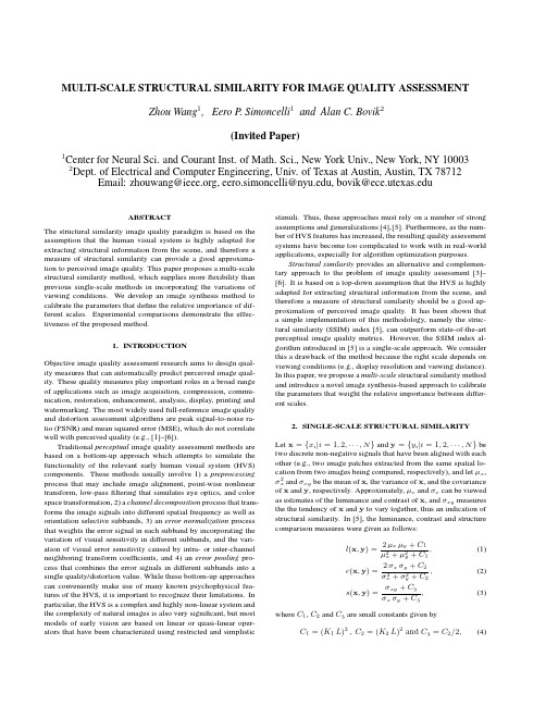
MULTI-SCALE STRUCTURAL SIMILARITY FOR IMAGE QUALITY ASSESSMENT Zhou Wang1,Eero P.Simoncelli1and Alan C.Bovik2(Invited Paper)1Center for Neural Sci.and Courant Inst.of Math.Sci.,New York Univ.,New York,NY10003 2Dept.of Electrical and Computer Engineering,Univ.of Texas at Austin,Austin,TX78712 Email:zhouwang@,eero.simoncelli@,bovik@ABSTRACTThe structural similarity image quality paradigm is based on the assumption that the human visual system is highly adapted for extracting structural information from the scene,and therefore a measure of structural similarity can provide a good approxima-tion to perceived image quality.This paper proposes a multi-scale structural similarity method,which supplies moreflexibility than previous single-scale methods in incorporating the variations of viewing conditions.We develop an image synthesis method to calibrate the parameters that define the relative importance of dif-ferent scales.Experimental comparisons demonstrate the effec-tiveness of the proposed method.1.INTRODUCTIONObjective image quality assessment research aims to design qual-ity measures that can automatically predict perceived image qual-ity.These quality measures play important roles in a broad range of applications such as image acquisition,compression,commu-nication,restoration,enhancement,analysis,display,printing and watermarking.The most widely used full-reference image quality and distortion assessment algorithms are peak signal-to-noise ra-tio(PSNR)and mean squared error(MSE),which do not correlate well with perceived quality(e.g.,[1]–[6]).Traditional perceptual image quality assessment methods are based on a bottom-up approach which attempts to simulate the functionality of the relevant early human visual system(HVS) components.These methods usually involve1)a preprocessing process that may include image alignment,point-wise nonlinear transform,low-passfiltering that simulates eye optics,and color space transformation,2)a channel decomposition process that trans-forms the image signals into different spatial frequency as well as orientation selective subbands,3)an error normalization process that weights the error signal in each subband by incorporating the variation of visual sensitivity in different subbands,and the vari-ation of visual error sensitivity caused by intra-or inter-channel neighboring transform coefficients,and4)an error pooling pro-cess that combines the error signals in different subbands into a single quality/distortion value.While these bottom-up approaches can conveniently make use of many known psychophysical fea-tures of the HVS,it is important to recognize their limitations.In particular,the HVS is a complex and highly non-linear system and the complexity of natural images is also very significant,but most models of early vision are based on linear or quasi-linear oper-ators that have been characterized using restricted and simplistic stimuli.Thus,these approaches must rely on a number of strong assumptions and generalizations[4],[5].Furthermore,as the num-ber of HVS features has increased,the resulting quality assessment systems have become too complicated to work with in real-world applications,especially for algorithm optimization purposes.Structural similarity provides an alternative and complemen-tary approach to the problem of image quality assessment[3]–[6].It is based on a top-down assumption that the HVS is highly adapted for extracting structural information from the scene,and therefore a measure of structural similarity should be a good ap-proximation of perceived image quality.It has been shown that a simple implementation of this methodology,namely the struc-tural similarity(SSIM)index[5],can outperform state-of-the-art perceptual image quality metrics.However,the SSIM index al-gorithm introduced in[5]is a single-scale approach.We consider this a drawback of the method because the right scale depends on viewing conditions(e.g.,display resolution and viewing distance). In this paper,we propose a multi-scale structural similarity method and introduce a novel image synthesis-based approach to calibrate the parameters that weight the relative importance between differ-ent scales.2.SINGLE-SCALE STRUCTURAL SIMILARITYLet x={x i|i=1,2,···,N}and y={y i|i=1,2,···,N}be two discrete non-negative signals that have been aligned with each other(e.g.,two image patches extracted from the same spatial lo-cation from two images being compared,respectively),and letµx,σ2x andσxy be the mean of x,the variance of x,and the covariance of x and y,respectively.Approximately,µx andσx can be viewed as estimates of the luminance and contrast of x,andσxy measures the the tendency of x and y to vary together,thus an indication of structural similarity.In[5],the luminance,contrast and structure comparison measures were given as follows:l(x,y)=2µxµy+C1µ2x+µ2y+C1,(1)c(x,y)=2σxσy+C2σ2x+σ2y+C2,(2)s(x,y)=σxy+C3σxσy+C3,(3) where C1,C2and C3are small constants given byC1=(K1L)2,C2=(K2L)2and C3=C2/2,(4)Fig.1.Multi-scale structural similarity measurement system.L:low-passfiltering;2↓:downsampling by2. respectively.L is the dynamic range of the pixel values(L=255for8bits/pixel gray scale images),and K1 1and K2 1aretwo scalar constants.The general form of the Structural SIMilarity(SSIM)index between signal x and y is defined as:SSIM(x,y)=[l(x,y)]α·[c(x,y)]β·[s(x,y)]γ,(5)whereα,βandγare parameters to define the relative importanceof the three components.Specifically,we setα=β=γ=1,andthe resulting SSIM index is given bySSIM(x,y)=(2µxµy+C1)(2σxy+C2)(µ2x+µ2y+C1)(σ2x+σ2y+C2),(6)which satisfies the following conditions:1.symmetry:SSIM(x,y)=SSIM(y,x);2.boundedness:SSIM(x,y)≤1;3.unique maximum:SSIM(x,y)=1if and only if x=y.The universal image quality index proposed in[3]corresponds to the case of C1=C2=0,therefore is a special case of(6).The drawback of such a parameter setting is that when the denominator of Eq.(6)is close to0,the resulting measurement becomes unsta-ble.This problem has been solved successfully in[5]by adding the two small constants C1and C2(calculated by setting K1=0.01 and K2=0.03,respectively,in Eq.(4)).We apply the SSIM indexing algorithm for image quality as-sessment using a sliding window approach.The window moves pixel-by-pixel across the whole image space.At each step,the SSIM index is calculated within the local window.If one of the image being compared is considered to have perfect quality,then the resulting SSIM index map can be viewed as the quality map of the other(distorted)image.Instead of using an8×8square window as in[3],a smooth windowing approach is used for local statistics to avoid“blocking artifacts”in the quality map[5].Fi-nally,a mean SSIM index of the quality map is used to evaluate the overall image quality.3.MULTI-SCALE STRUCTURAL SIMILARITY3.1.Multi-scale SSIM indexThe perceivability of image details depends the sampling density of the image signal,the distance from the image plane to the ob-server,and the perceptual capability of the observer’s visual sys-tem.In practice,the subjective evaluation of a given image varies when these factors vary.A single-scale method as described in the previous section may be appropriate only for specific settings.Multi-scale method is a convenient way to incorporate image de-tails at different resolutions.We propose a multi-scale SSIM method for image quality as-sessment whose system diagram is illustrated in Fig. 1.Taking the reference and distorted image signals as the input,the system iteratively applies a low-passfilter and downsamples thefiltered image by a factor of2.We index the original image as Scale1, and the highest scale as Scale M,which is obtained after M−1 iterations.At the j-th scale,the contrast comparison(2)and the structure comparison(3)are calculated and denoted as c j(x,y) and s j(x,y),respectively.The luminance comparison(1)is com-puted only at Scale M and is denoted as l M(x,y).The overall SSIM evaluation is obtained by combining the measurement at dif-ferent scales usingSSIM(x,y)=[l M(x,y)]αM·Mj=1[c j(x,y)]βj[s j(x,y)]γj.(7)Similar to(5),the exponentsαM,βj andγj are used to ad-just the relative importance of different components.This multi-scale SSIM index definition satisfies the three conditions given in the last section.It also includes the single-scale method as a spe-cial case.In particular,a single-scale implementation for Scale M applies the iterativefiltering and downsampling procedure up to Scale M and only the exponentsαM,βM andγM are given non-zero values.To simplify parameter selection,we letαj=βj=γj forall j’s.In addition,we normalize the cross-scale settings such thatMj=1γj=1.This makes different parameter settings(including all single-scale and multi-scale settings)comparable.The remain-ing job is to determine the relative values across different scales. Conceptually,this should be related to the contrast sensitivity func-tion(CSF)of the HVS[7],which states that the human visual sen-sitivity peaks at middle frequencies(around4cycles per degree of visual angle)and decreases along both high-and low-frequency directions.However,CSF cannot be directly used to derive the parameters in our system because it is typically measured at the visibility threshold level using simplified stimuli(sinusoids),but our purpose is to compare the quality of complex structured im-ages at visible distortion levels.3.2.Cross-scale calibrationWe use an image synthesis approach to calibrate the relative impor-tance of different scales.In previous work,the idea of synthesizing images for subjective testing has been employed by the“synthesis-by-analysis”methods of assessing statistical texture models,inwhich the model is used to generate a texture with statistics match-ing an original texture,and a human subject then judges the sim-ilarity of the two textures [8]–[11].A similar approach has also been qualitatively used in demonstrating quality metrics in [5],[12],though quantitative subjective tests were not conducted.These synthesis methods provide a powerful and efficient means of test-ing a model,and have the added benefit that the resulting images suggest improvements that might be made to the model[11].M )distortion level (MSE)12345Fig.2.Demonstration of image synthesis approach for cross-scale calibration.Images in the same row have the same MSE.Images in the same column have distortions only in one specific scale.Each subject was asked to select a set of images (one from each scale),having equal quality.As an example,one subject chose the marked images.For a given original 8bits/pixel gray scale test image,we syn-thesize a table of distorted images (as exemplified by Fig.2),where each entry in the table is an image that is associated witha specific distortion level (defined by MSE)and a specific scale.Each of the distorted image is created using an iterative procedure,where the initial image is generated by randomly adding white Gaussian noise to the original image and the iterative process em-ploys a constrained gradient descent algorithm to search for the worst images in terms of SSIM measure while constraining MSE to be fixed and restricting the distortions to occur only in the spec-ified scale.We use 5scales and 12distortion levels (range from 23to 214)in our experiment,resulting in a total of 60images,as demonstrated in Fig.2.Although the images at each row has the same MSE with respect to the original image,their visual quality is significantly different.Thus the distortions at different scales are of very different importance in terms of perceived image quality.We employ 10original 64×64images with different types of con-tent (human faces,natural scenes,plants,man-made objects,etc.)in our experiment to create 10sets of distorted images (a total of 600distorted images).We gathered data for 8subjects,including one of the authors.The other subjects have general knowledge of human vision but did not know the detailed purpose of the study.Each subject was shown the 10sets of test images,one set at a time.The viewing dis-tance was fixed to 32pixels per degree of visual angle.The subject was asked to compare the quality of the images across scales and detect one image from each of the five scales (shown as columns in Fig.2)that the subject believes having the same quality.For example,one subject chose the images marked in Fig.2to have equal quality.The positions of the selected images in each scale were recorded and averaged over all test images and all subjects.In general,the subjects agreed with each other on each image more than they agreed with themselves across different images.These test results were normalized (sum to one)and used to calculate the exponents in Eq.(7).The resulting parameters we obtained are β1=γ1=0.0448,β2=γ2=0.2856,β3=γ3=0.3001,β4=γ4=0.2363,and α5=β5=γ5=0.1333,respectively.4.TEST RESULTSWe test a number of image quality assessment algorithms using the LIVE database (available at [13]),which includes 344JPEG and JPEG2000compressed images (typically 768×512or similar size).The bit rate ranges from 0.028to 3.150bits/pixel,which allows the test images to cover a wide quality range,from in-distinguishable from the original image to highly distorted.The mean opinion score (MOS)of each image is obtained by averag-ing 13∼25subjective scores given by a group of human observers.Eight image quality assessment models are being compared,in-cluding PSNR,the Sarnoff model (JNDmetrix 8.0[14]),single-scale SSIM index with M equals 1to 5,and the proposed multi-scale SSIM index approach.The scatter plots of MOS versus model predictions are shown in Fig.3,where each point represents one test image,with its vertical and horizontal axes representing its MOS and the given objective quality score,respectively.To provide quantitative per-formance evaluation,we use the logistic function adopted in the video quality experts group (VQEG)Phase I FR-TV test [15]to provide a non-linear mapping between the objective and subjective scores.After the non-linear mapping,the linear correlation coef-ficient (CC),the mean absolute error (MAE),and the root mean squared error (RMS)between the subjective and objective scores are calculated as measures of prediction accuracy .The prediction consistency is quantified using the outlier ratio (OR),which is de-Table1.Performance comparison of image quality assessment models on LIVE JPEG/JPEG2000database[13].SS-SSIM: single-scale SSIM;MS-SSIM:multi-scale SSIM;CC:non-linear regression correlation coefficient;ROCC:Spearman rank-order correlation coefficient;MAE:mean absolute error;RMS:root mean squared error;OR:outlier ratio.Model CC ROCC MAE RMS OR(%)PSNR0.9050.901 6.538.4515.7Sarnoff0.9560.947 4.66 5.81 3.20 SS-SSIM(M=1)0.9490.945 4.96 6.25 6.98 SS-SSIM(M=2)0.9630.959 4.21 5.38 2.62 SS-SSIM(M=3)0.9580.956 4.53 5.67 2.91 SS-SSIM(M=4)0.9480.946 4.99 6.31 5.81 SS-SSIM(M=5)0.9380.936 5.55 6.887.85 MS-SSIM0.9690.966 3.86 4.91 1.16fined as the percentage of the number of predictions outside the range of±2times of the standard deviations.Finally,the predic-tion monotonicity is measured using the Spearman rank-order cor-relation coefficient(ROCC).Readers can refer to[15]for a more detailed descriptions of these measures.The evaluation results for all the models being compared are given in Table1.From both the scatter plots and the quantitative evaluation re-sults,we see that the performance of single-scale SSIM model varies with scales and the best performance is given by the case of M=2.It can also be observed that the single-scale model tends to supply higher scores with the increase of scales.This is not surprising because image coding techniques such as JPEG and JPEG2000usually compressfine-scale details to a much higher degree than coarse-scale structures,and thus the distorted image “looks”more similar to the original image if evaluated at larger scales.Finally,for every one of the objective evaluation criteria, multi-scale SSIM model outperforms all the other models,includ-ing the best single-scale SSIM model,suggesting a meaningful balance between scales.5.DISCUSSIONSWe propose a multi-scale structural similarity approach for image quality assessment,which provides moreflexibility than single-scale approach in incorporating the variations of image resolution and viewing conditions.Experiments show that with an appropri-ate parameter settings,the multi-scale method outperforms the best single-scale SSIM model as well as state-of-the-art image quality metrics.In the development of top-down image quality models(such as structural similarity based algorithms),one of the most challeng-ing problems is to calibrate the model parameters,which are rather “abstract”and cannot be directly derived from simple-stimulus subjective experiments as in the bottom-up models.In this pa-per,we used an image synthesis approach to calibrate the param-eters that define the relative importance between scales.The im-provement from single-scale to multi-scale methods observed in our tests suggests the usefulness of this novel approach.However, this approach is still rather crude.We are working on developing it into a more systematic approach that can potentially be employed in a much broader range of applications.6.REFERENCES[1] A.M.Eskicioglu and P.S.Fisher,“Image quality mea-sures and their performance,”IEEE munications, vol.43,pp.2959–2965,Dec.1995.[2]T.N.Pappas and R.J.Safranek,“Perceptual criteria for im-age quality evaluation,”in Handbook of Image and Video Proc.(A.Bovik,ed.),Academic Press,2000.[3]Z.Wang and A.C.Bovik,“A universal image quality in-dex,”IEEE Signal Processing Letters,vol.9,pp.81–84,Mar.2002.[4]Z.Wang,H.R.Sheikh,and A.C.Bovik,“Objective videoquality assessment,”in The Handbook of Video Databases: Design and Applications(B.Furht and O.Marques,eds.), pp.1041–1078,CRC Press,Sept.2003.[5]Z.Wang,A.C.Bovik,H.R.Sheikh,and E.P.Simon-celli,“Image quality assessment:From error measurement to structural similarity,”IEEE Trans.Image Processing,vol.13, Jan.2004.[6]Z.Wang,L.Lu,and A.C.Bovik,“Video quality assessmentbased on structural distortion measurement,”Signal Process-ing:Image Communication,special issue on objective video quality metrics,vol.19,Jan.2004.[7] B.A.Wandell,Foundations of Vision.Sinauer Associates,Inc.,1995.[8]O.D.Faugeras and W.K.Pratt,“Decorrelation methods oftexture feature extraction,”IEEE Pat.Anal.Mach.Intell., vol.2,no.4,pp.323–332,1980.[9] A.Gagalowicz,“A new method for texturefields synthesis:Some applications to the study of human vision,”IEEE Pat.Anal.Mach.Intell.,vol.3,no.5,pp.520–533,1981. [10] D.Heeger and J.Bergen,“Pyramid-based texture analy-sis/synthesis,”in Proc.ACM SIGGRAPH,pp.229–238,As-sociation for Computing Machinery,August1995.[11]J.Portilla and E.P.Simoncelli,“A parametric texture modelbased on joint statistics of complex wavelet coefficients,”Int’l J Computer Vision,vol.40,pp.49–71,Dec2000. [12]P.C.Teo and D.J.Heeger,“Perceptual image distortion,”inProc.SPIE,vol.2179,pp.127–141,1994.[13]H.R.Sheikh,Z.Wang, A. C.Bovik,and L.K.Cormack,“Image and video quality assessment re-search at LIVE,”/ research/quality/.[14]Sarnoff Corporation,“JNDmetrix Technology,”http:///products_services/video_vision/jndmetrix/.[15]VQEG,“Final report from the video quality experts groupon the validation of objective models of video quality assess-ment,”Mar.2000./.PSNRM O SSarnoffM O S(a)(b)Single−scale SSIM (M=1)M O SSingle−scale SSIM (M=2)M O S(c)(d)Single−scale SSIM (M=3)M O SSingle−scale SSIM (M=4)M O S(e)(f)Single−scale SSIM (M=5)M O SMulti−scale SSIMM O S(g)(h)Fig.3.Scatter plots of MOS versus model predictions.Each sample point represents one test image in the LIVE JPEG/JPEG2000image database [13].(a)PSNR;(b)Sarnoff model;(c)-(g)single-scale SSIM method for M =1,2,3,4and 5,respectively;(h)multi-scale SSIM method.。
多尺度特征融合的脊柱X线图像分割方法

脊柱侧凸是一种脊柱三维结构的畸形疾病,全球有1%~4%的青少年受到此疾病的影响[1]。
该疾病的诊断主要参考患者的脊柱侧凸角度,目前X线成像方式是诊断脊柱侧凸的首选,在X线图像中分割脊柱是后续测量、配准以及三维重建的基础。
近期出现了不少脊柱X线图像分割方法。
Anitha等人[2-3]提出了使用自定义的滤波器自动提取椎体终板以及自动获取轮廓的形态学算子的方法,但这些方法存在一定的观察者间的误差。
Sardjono等人[4]提出基于带电粒子模型的物理方法来提取脊柱轮廓,实现过程复杂且实用性不高。
叶伟等人[5]提出了一种基于模糊C均值聚类分割算法,该方法过程繁琐且实用性欠佳。
以上方法都只对椎体进行了分割,却无法实现对脊柱的整体轮廓分割。
深度学习在图像分割的领域有很多应用。
Long等人提出了全卷积网络[6](Full Convolutional Network,FCN),将卷积神经网络的最后一层全连接层替换为卷积层,得到特征图后再经过反卷积来获得像素级的分类结果。
通过对FCN结构改进,Ronneberger等人提出了一种编码-解码的网络结构U-Net[7]解决图像分割问题。
Wu等人提出了BoostNet[8]来对脊柱X线图像进行目标检测以及一个基于多视角的相关网络[9]来完成对脊柱框架的定位。
上述方法并未直接对脊柱图像进行分割,仅提取了关键点的特征并由定位的特征来获取脊柱的整体轮廓。
Fang等人[10]采用FCN对脊柱的CT切片图像进行分割并进行三维重建,但分割精度相对较低。
Horng等人[11]将脊柱X线图像进行切割后使用残差U-Net 来对单个椎骨进行分割,再合成完整的脊柱图像,从而导致分割过程过于繁琐。
Tan等人[12]和Grigorieva等人[13]采用U-Net来对脊柱X线图像进行分割并实现对Cobb角的测量或三维重建,但存在分割精度不高的问题。
以上研究方法虽然在一定程度上完成脊柱分割,但仍存在两个问题:(1)只涉及椎体的定位和计算脊柱侧凸角度,却没有对图像进行完整的脊柱分割。
人脸识别 面部 数字图像处理相关 中英对照 外文文献翻译 毕业设计论文 高质量人工翻译 原文带出处

人脸识别相关文献翻译,纯手工翻译,带原文出处(原文及译文)如下翻译原文来自Thomas David Heseltine BSc. Hons. The University of YorkDepartment of Computer ScienceFor the Qualification of PhD. — September 2005 -《Face Recognition: Two-Dimensional and Three-Dimensional Techniques》4 Two-dimensional Face Recognition4.1 Feature LocalizationBefore discussing the methods of comparing two facial images we now take a brief look at some at the preliminary processes of facial feature alignment. This process typically consists of two stages: face detection and eye localisation. Depending on the application, if the position of the face within the image is known beforehand (fbr a cooperative subject in a door access system fbr example) then the face detection stage can often be skipped, as the region of interest is already known. Therefore, we discuss eye localisation here, with a brief discussion of face detection in the literature review(section 3.1.1).The eye localisation method is used to align the 2D face images of the various test sets used throughout this section. However, to ensure that all results presented are representative of the face recognition accuracy and not a product of the performance of the eye localisation routine, all image alignments are manually checked and any errors corrected, prior to testing and evaluation.We detect the position of the eyes within an image using a simple template based method. A training set of manually pre-aligned images of feces is taken, and each image cropped to an area around both eyes. The average image is calculated and used as a template.Figure 4-1 - The average eyes. Used as a template for eye detection.Both eyes are included in a single template, rather than individually searching for each eye in turn, as the characteristic symmetry of the eyes either side of the nose, provides a useful feature that helps distinguish between the eyes and other false positives that may be picked up in the background. Although this method is highly susceptible to scale(i.e. subject distance from the camera) and also introduces the assumption that eyes in the image appear near horizontal. Some preliminary experimentation also reveals that it is advantageous to include the area of skin justbeneath the eyes. The reason being that in some cases the eyebrows can closely match the template, particularly if there are shadows in the eye-sockets, but the area of skin below the eyes helps to distinguish the eyes from eyebrows (the area just below the eyebrows contain eyes, whereas the area below the eyes contains only plain skin).A window is passed over the test images and the absolute difference taken to that of the average eye image shown above. The area of the image with the lowest difference is taken as the region of interest containing the eyes. Applying the same procedure using a smaller template of the individual left and right eyes then refines each eye position.This basic template-based method of eye localisation, although providing fairly preciselocalisations, often fails to locate the eyes completely. However, we are able to improve performance by including a weighting scheme.Eye localisation is performed on the set of training images, which is then separated into two sets: those in which eye detection was successful; and those in which eye detection failed. Taking the set of successful localisations we compute the average distance from the eye template (Figure 4-2 top). Note that the image is quite dark, indicating that the detected eyes correlate closely to the eye template, as we would expect. However, bright points do occur near the whites of the eye, suggesting that this area is often inconsistent, varying greatly from the average eye template.Figure 4-2 一Distance to the eye template for successful detections (top) indicating variance due to noise and failed detections (bottom) showing credible variance due to miss-detected features.In the lower image (Figure 4-2 bottom), we have taken the set of failed localisations(images of the forehead, nose, cheeks, background etc. falsely detected by the localisation routine) and once again computed the average distance from the eye template. The bright pupils surrounded by darker areas indicate that a failed match is often due to the high correlation of the nose and cheekbone regions overwhelming the poorly correlated pupils. Wanting to emphasise the difference of the pupil regions for these failed matches and minimise the variance of the whites of the eyes for successful matches, we divide the lower image values by the upper image to produce a weights vector as shown in Figure 4-3. When applied to the difference image before summing a total error, this weighting scheme provides a much improved detection rate.Figure 4-3 - Eye template weights used to give higher priority to those pixels that best represent the eyes.4.2 The Direct Correlation ApproachWe begin our investigation into face recognition with perhaps the simplest approach,known as the direct correlation method (also referred to as template matching by Brunelli and Poggio [29 ]) involving the direct comparison of pixel intensity values taken from facial images. We use the term "Direct Conelation, to encompass all techniques in which face images are compared directly, without any form of image space analysis, weighting schemes or feature extraction, regardless of the distance metric used. Therefore, we do not infer that Pearson's correlation is applied as the similarity function (although such an approach would obviously come under our definition of direct correlation). We typically use the Euclidean distance as our metric in these investigations (inversely related to Pearson's correlation and can be considered as a scale and translation sensitive form of image correlation), as this persists with the contrast made between image space and subspace approaches in later sections.Firstly, all facial images must be aligned such that the eye centres are located at two specified pixel coordinates and the image cropped to remove any background information. These images are stored as greyscale bitmaps of 65 by 82 pixels and prior to recognition converted into a vector of 5330 elements (each element containing the corresponding pixel intensity value). Each corresponding vector can be thought of as describing a point within a 5330 dimensional image space. This simple principle can easily be extended to much larger images: a 256 by 256 pixel image occupies a single point in 65,536-dimensional image space and again, similar images occupy close points within that space. Likewise, similar faces are located close together within the image space, while dissimilar faces are spaced far apart. Calculating the Euclidean distance d, between two facial image vectors (often referred to as the query image q, and gallery image g), we get an indication of similarity. A threshold is then applied to make the final verification decision.d . q - g ( threshold accept ) (d threshold ⇒ reject ). Equ. 4-14.2.1 Verification TestsThe primary concern in any face recognition system is its ability to correctly verify a claimed identity or determine a person's most likely identity from a set of potential matches in a database. In order to assess a given system's ability to perform these tasks, a variety of evaluation methodologies have arisen. Some of these analysis methods simulate a specific mode of operation (i.e. secure site access or surveillance), while others provide a more mathematicaldescription of data distribution in some classification space. In addition, the results generated from each analysis method may be presented in a variety of formats. Throughout the experimentations in this thesis, we primarily use the verification test as our method of analysis and comparison, although we also use Fisher's Linear Discriminant to analyse individual subspace components in section 7 and the identification test for the final evaluations described in section 8. The verification test measures a system's ability to correctly accept or reject the proposed identity of an individual. At a functional level, this reduces to two images being presented for comparison, fbr which the system must return either an acceptance (the two images are of the same person) or rejection (the two images are of different people). The test is designed to simulate the application area of secure site access. In this scenario, a subject will present some form of identification at a point of entry, perhaps as a swipe card, proximity chip or PIN number. This number is then used to retrieve a stored image from a database of known subjects (often referred to as the target or gallery image) and compared with a live image captured at the point of entry (the query image). Access is then granted depending on the acceptance/rej ection decision.The results of the test are calculated according to how many times the accept/reject decision is made correctly. In order to execute this test we must first define our test set of face images. Although the number of images in the test set does not affect the results produced (as the error rates are specified as percentages of image comparisons), it is important to ensure that the test set is sufficiently large such that statistical anomalies become insignificant (fbr example, a couple of badly aligned images matching well). Also, the type of images (high variation in lighting, partial occlusions etc.) will significantly alter the results of the test. Therefore, in order to compare multiple face recognition systems, they must be applied to the same test set.However, it should also be noted that if the results are to be representative of system performance in a real world situation, then the test data should be captured under precisely the same circumstances as in the application environment.On the other hand, if the purpose of the experimentation is to evaluate and improve a method of face recognition, which may be applied to a range of application environments, then the test data should present the range of difficulties that are to be overcome. This may mean including a greater percentage of6difficult9 images than would be expected in the perceived operating conditions and hence higher error rates in the results produced. Below we provide the algorithm for executing the verification test. The algorithm is applied to a single test set of face images, using a single function call to the face recognition algorithm: CompareF aces(F ace A, FaceB). This call is used to compare two facial images, returning a distance score indicating how dissimilar the two face images are: the lower the score the more similar the two face images. Ideally, images of the same face should produce low scores, while images of different faces should produce high scores.Every image is compared with every other image, no image is compared with itself and nopair is compared more than once (we assume that the relationship is symmetrical). Once two images have been compared, producing a similarity score, the ground-truth is used to determine if the images are of the same person or different people. In practical tests this information is often encapsulated as part of the image filename (by means of a unique person identifier). Scores are then stored in one of two lists: a list containing scores produced by comparing images of different people and a list containing scores produced by comparing images of the same person. The final acceptance/rejection decision is made by application of a threshold. Any incorrect decision is recorded as either a false acceptance or false rejection. The false rejection rate (FRR) is calculated as the percentage of scores from the same people that were classified as rejections. The false acceptance rate (FAR) is calculated as the percentage of scores from different people that were classified as acceptances.For IndexA = 0 to length(TestSet) For IndexB = IndexA+l to length(TestSet) Score = CompareFaces(TestSet[IndexA], TestSet[IndexB]) If IndexA and IndexB are the same person Append Score to AcceptScoresListElseAppend Score to RejectScoresListFor Threshold = Minimum Score to Maximum Score:FalseAcceptCount, FalseRejectCount = 0For each Score in RejectScoresListIf Score <= ThresholdIncrease FalseAcceptCountFor each Score in AcceptScoresListIf Score > ThresholdIncrease FalseRejectCountF alse AcceptRate = FalseAcceptCount / Length(AcceptScoresList)FalseRej ectRate = FalseRejectCount / length(RejectScoresList)Add plot to error curve at (FalseRejectRate, FalseAcceptRate)These two error rates express the inadequacies of the system when operating at aspecific threshold value. Ideally, both these figures should be zero, but in reality reducing either the FAR or FRR (by altering the threshold value) will inevitably resultin increasing the other. Therefore, in order to describe the full operating range of a particular system, we vary the threshold value through the entire range of scores produced. The application of each threshold value produces an additional FAR, FRR pair, which when plotted on a graph produces the error rate curve shown below.False Acceptance Rate / %Figure 4-5 - Example Error Rate Curve produced by the verification test.The equal error rate (EER) can be seen as the point at which FAR is equal to FRR. This EER value is often used as a single figure representing the general recognition performance of a biometric system and allows for easy visual comparison of multiple methods. However, it is important to note that the EER does not indicate the level of error that would be expected in a real world application. It is unlikely that any real system would use a threshold value such that the percentage of false acceptances were equal to the percentage of false rejections. Secure site access systems would typically set the threshold such that false acceptances were significantly lower than false rejections: unwilling to tolerate intruders at the cost of inconvenient access denials.Surveillance systems on the other hand would require low false rejection rates to successfully identify people in a less controlled environment. Therefore we should bear in mind that a system with a lower EER might not necessarily be the better performer towards the extremes of its operating capability.There is a strong connection between the above graph and the receiver operating characteristic (ROC) curves, also used in such experiments. Both graphs are simply two visualisations of the same results, in that the ROC format uses the True Acceptance Rate(TAR), where TAR = 1.0 - FRR in place of the FRR, effectively flipping the graph vertically. Another visualisation of the verification test results is to display both the FRR and FAR as functions of the threshold value. This presentation format provides a reference to determine the threshold value necessary to achieve a specific FRR and FAR. The EER can be seen as the point where the two curves intersect.Figure 4-6 - Example error rate curve as a function of the score threshold The fluctuation of these error curves due to noise and other errors is dependant on the number of face image comparisons made to generate the data. A small dataset that only allows fbr a small number of comparisons will results in a jagged curve, in which large steps correspond to the influence of a single image on a high proportion of the comparisons made. A typical dataset of 720 images (as used in section 4.2.2) provides 258,840 verification operations, hence a drop of 1% EER represents an additional 2588 correct decisions, whereas the quality of a single image could cause the EER to fluctuate by up to 0.28.422 ResultsAs a simple experiment to test the direct correlation method, we apply the technique described above to a test set of 720 images of 60 different people, taken from the AR Face Database [ 39 ]. Every image is compared with every other image in the test set to produce a likeness score, providing 258,840 verification operations from which to calculate false acceptance rates and false rejection rates. The error curve produced is shown in Figure 4-7.Figure 4-7 - Error rate curve produced by the direct correlation method using no image preprocessing.We see that an EER of 25.1% is produced, meaning that at the EER threshold approximately one quarter of all verification operations carried out resulted in an incorrect classification. Thereare a number of well-known reasons for this poor level of accuracy. Tiny changes in lighting, expression or head orientation cause the location in image space to change dramatically. Images in face space are moved far apart due to these image capture conditions, despite being of the same person's face. The distance between images of different people becomes smaller than the area of face space covered by images of the same person and hence false acceptances and false rejections occur frequently. Other disadvantages include the large amount of storage necessaryfor holding many face images and the intensive processing required for each comparison, making this method unsuitable fbr applications applied to a large database. In section 4.3 we explore the eigenface method, which attempts to address some of these issues.4二维人脸识别4.1功能定位在讨论比较两个人脸图像,我们现在就简要介绍的方法一些在人脸特征的初步调整过程。
图像检测外文翻译参考文献

图像检测外文翻译参考文献(文档含中英文对照即英文原文和中文翻译)译文基于半边脸的人脸检测概要:图像中的人脸检测是人脸识别研究中一项非常重要的研究分支。
为了更有效地检测图像中的人脸,此次研究设计提出了基于半边脸的人脸检测方法。
根据图像中人半边脸的容貌或者器官的密度特征,比如眼睛,耳朵,嘴巴,部分脸颊,正面的平均全脸模板就可以被构建出来。
被模拟出来的半张脸是基于人脸的对称性的特点而构建的。
图像中人脸检测的实验运用了模板匹配法和相似性从而确定人脸在图像中的位置。
此原理分析显示了平均全脸模型法能够有效地减少模板的局部密度的不确定性。
基于半边脸的人脸检测能降低人脸模型密度的过度对称性,从而提高人脸检测的速度。
实验结果表明此方法还适用于在大角度拍下的侧脸图像,这大大增加了侧脸检测的准确性。
关键词:人脸模板,半边人脸模板,模板匹配法,相似性,侧脸。
I.介绍近几年,在图像处理和识别以及计算机视觉的研究领域中,人脸识别是一个很热门的话题。
作为人脸识别中一个重要的环节,人脸检测也拥有一个延伸的研究领域。
人脸检测的主要目的是为了确定图像中的信息,比如,图像总是否存在人脸,它的位置,旋转角度以及人脸的姿势。
根据人脸的不同特征,人脸检测的方法也有所变化[1-4]。
而且,根据人脸器官的密度或颜色的固定布局,我们可以判定是否存在人脸。
因此,这种基于肤色模型和模板匹配的方法对于人脸检测具有重要的研究意义[5-7]。
这种基于模板匹配的人脸检测法是选择正面脸部的特征作为匹配的模板,导致人脸搜索的计算量相对较大。
然而,绝大多数的人脸都是对称的。
所以我们可以选择半边正面人脸模板,也就是说,选择左半边脸或者有半边脸作为人脸匹配的模板,这样,大大减少了人脸搜索的计算。
II.人脸模板构建的方法人脸模板的质量直接影响匹配识别的效果。
为了减少模板局部密度的不确定性,构建人脸模板是基于大众脸的信息,例如,平均的眼睛模板,平均的脸型模板。
这种方法很简单。
基于多通道图像深度学习的恶意代码检测

2021⁃04⁃10计算机应用,Journal of Computer Applications2021,41(4):1142-1147ISSN 1001⁃9081CODEN JYIIDU http ://基于多通道图像深度学习的恶意代码检测蒋考林,白玮,张磊,陈军,潘志松*,郭世泽(陆军工程大学指挥控制工程学院,南京210007)(∗通信作者电子邮箱hotpzs@ )摘要:现有基于深度学习的恶意代码检测方法存在深层次特征提取能力偏弱、模型相对复杂、模型泛化能力不足等问题。
同时,代码复用现象在同一类恶意样本中大量存在,而代码复用会导致代码的视觉特征相似,这种相似性可以被用来进行恶意代码检测。
因此,提出一种基于多通道图像视觉特征和AlexNet 神经网络的恶意代码检测方法。
该方法首先将待检测的代码转化为多通道图像,然后利用AlexNet 神经网络提取其彩色纹理特征并对这些特征进行分类从而检测出可能的恶意代码;同时通过综合运用多通道图像特征提取、局部响应归一化(LRN )等技术,在有效降低模型复杂度的基础上提升了模型的泛化能力。
利用均衡处理后的Malimg 数据集进行测试,结果显示该方法的平均分类准确率达到97.8%;相较于VGGNet 方法在准确率上提升了1.8%,在检测效率上提升了60.2%。
实验结果表明,多通道图像彩色纹理特征能较好地反映恶意代码的类别信息,AlexNet 神经网络相对简单的结构能有效地提升检测效率,而局部响应归一化能提升模型的泛化能力与检测效果。
关键词:多通道图像;彩色纹理特征;恶意代码;深度学习;局部响应归一化中图分类号:TP309文献标志码:AMalicious code detection based on multi -channel image deep learningJIANG Kaolin ,BAI Wei ,ZHANG Lei ,CHEN Jun ,PAN Zhisong *,GUO Shize(Command and Control Engineering College ,Army Engineering University Nanjing Jiangsu 210007,China )Abstract:Existing deep learning -based malicious code detection methods have problems such as weak deep -level feature extraction capability ,relatively complex model and insufficient model generalization capability.At the same time ,code reuse phenomenon occurred in large number of malicious samples of the same type ,resulting in similar visual features of the code.This similarity can be used for malicious code detection.Therefore ,a malicious code detection method based on multi -channel image visual features and AlexNet was proposed.In the method ,the codes to be detected were converted into multi -channel images at first.After that ,AlexNet was used to extract and classify the color texture features of the images ,so as to detect the possible malicious codes.Meanwhile ,the multi -channel image feature extraction ,the Local Response Normalization (LRN )and other technologies were used comprehensively ,which effectively improved the generalization ability of the model with effective reduction of the complexity of the model.The Malimg dataset after equalization was used for testing ,the results showed that the average classification accuracy of the proposed method was 97.8%,and the method had the accuracy increased by 1.8%and the detection efficiency increased by 60.2%compared with the VGGNet method.Experimental results show that the color texture features of multi -channel images can better reflect the type information of malicious codes ,the simple network structure of AlexNet can effectively improve the detection efficiency ,and the local response normalization can improve the generalization ability and detection effect of the model.Key words:multi -channel image;color texture feature;malicious code;deep learning;Local Response Normalization (LRN)引言恶意代码已经成为网络空间的主要威胁来源之一。
MPCA
pending on the variations observed in each subspace and the importance given to the associated factor [17]. The effectiveness of such a representation results in better face recognition performance than the linear models, as reported by Vasilescu et.al. in [16]. However, in their approach, only the person-mode decomposition is used for recognition, whilst other mode decompositions are used optionally to reduce the dimensionality of associated vector-spaces (e.g. removing the dimensions with low variance). More precisely, if we want to identify persons when the facial images are only subjected to varying lighting and viewpoints, a set of eigenmodes are calculated for each combination of lighting and viewpoint. These eigenmodes are similar to eigenfaces, however, whilst eigenfaces capture variations over all the images, eigenmodes capture variations over images at particular combinations of lighting and viewpoint. These eigenmodes constitute the basis of each vector space, and thus there is a separate vector space for each combination of lighting and viewpoint. The notion of multilinearity implies that for training images, each person is defined by the same coefficient vector across all the bases. A test image is projected on every basis and a set of candidate coefficient vectors is generated. The set is then compared pair-wise to the set of stored person-specific combination vectors and the best match is found. A similar approach has also been used in [18] for expression invariant face recognition, in [9] for simultaneous super-resolution and recognition and in [10] for gait recognition. A similar recognition approach has also been used for Multilinear ICA decomposition [15]. An analysis of these approaches reveals the following shortcomings: 1. Though multilinear decomposition is used, essentially they compute a set of coupled bases, based only on person-mode decomposition. This, we believe, is a severe under-utilisation of the multilinear decomposition, which provides a mechanism to unearth the hidden multilinear relationship between all factors of variations (i.e. person, lighting and viewpoint) 2. The recognition procedures in [16] [18] need to per-
多模态医学图像处理技术研究

多模态医学图像处理技术研究随着医疗技术的不断发展,医学图像分析与处理已成为医学研究和临床应用的重要组成部分。
同时,随着多模态成像设备的广泛应用,多模态医学图像处理技术的研究也越来越受到关注。
多模态医学图像处理技术是指利用多种成像技术获取的医学图像进行融合、配准、分割、识别等处理,从而获取更全面、准确的医学信息,提高医学图像的诊断和治疗价值。
多模态成像技术包括X射线、CT、MRI、超声、PET、SPECT等多种成像技术,它们各有优势和缺点,可以相互补充,提高医学图像的质量和可靠性。
本文将从多个方面介绍当前多模态医学图像处理技术的研究进展和应用。
一、多模态医学图像融合技术多模态医学图像融合技术是指将不同成像技术获得的医学图像信息进行去噪、配准、拼接等处理,得到一幅融合后的图像,以此提高图像分辨率和信息量,更好地反映病变的特征。
例如,融合MRI和PET图像,可以同时获取代谢和解剖信息,更准确地判断肿瘤位置和边界。
目前,多模态医学图像融合技术已有很多成果,例如基于小波变换的融合方法、基于机器学习的融合方法、基于深度学习的融合方法等。
这些方法中,基于深度学习的方法被认为是最稳健和高效的方法之一,它可以自动学习多个成像模态之间的非线性相关性,提高融合准确性和稳定性。
二、多模态医学图像配准技术多模态医学图像配准技术是指将不同成像技术获得的医学图像进行空间对齐和变换,以此消除不同成像条件下的位置、尺度和姿态变化,保证多模态图像的一致性和可比性。
例如,将MRI和CT图像进行配准,可以更好地观察患者的病变和解剖结构。
多模态医学图像配准技术是多模态医学图像处理的基础和关键,目前已有很多方法可供选择,例如局部特征描述和匹配、基于形态学和灰度信息的配准方法、基于深度学习的配准方法等。
其中,基于深度学习的配准方法被认为是最具前景的方法之一,它可以自动学习多模态医学图像的特征表示和相似性对齐,避免了人工设计和参数调整的繁琐过程。
细胞生物学 第五版 超高分辨率显微技术 名词解释

SIM
结构照明显微 Structure 术
Illumination
Microscopy
在显微镜的硬件系统增加光栅和控制元件 原理:通过光栅的旋转和移动将多重相互衍射的光束照射到样本上,并 再次发生干涉,然后从收集到的发射光模式中提取高分辨信息,生成一 幅完整的图像。 优点:对于普通的免疫荧光标记样本和各种荧光蛋白表达样本,无需特 殊处理直接观察 缺点:分辨率远低于其他超高分辨显微术。
随机光学重构
optical
心位置,重复 10000 次以上,可以重构出内源蛋白分布的高分辨图像。
显微术
reconstruction 名词解释:利用能在荧光态和暗状态之间不断切换的荧光探针标记待观
microscopy 察分子,任何一帧荧光像只探测一小部分光学上可分辨的荧光基团,因
此能非常精确地确定它们离荧光光斑中心位置的一种超高分辨率荧光显
缺点:只能观察外源表达蛋白的定位,不适合活细胞动态观察。
绿色荧光蛋白
PA-GFP 的突变体
PA-GFP 在激活之前对 488nm 的光没有反应,需先用 405nm 的激光激活 一段时间,再用 488nm 激光照射时才可发出绿色荧光。
作用:细胞内源性蛋白的超分辨定位。
染料:基于花青染料可以被一种波长的光激活发出荧光,也可以被另一
TIRFM
超高分辨率显 微技术Байду номын сангаас
PALM/STORM 4π STED 显微术
SIM
TIRFM
Total Internal 全内反射荧光
Reflection 显微术
Fluorescence
Microscopy
基于斯涅尔定律,当光线从光密介质进入光疏介质时,一部分光会发生 折射,而另一部分光会发生反射,当光线的入射角大于临界角时,会发 生全内反射(TIR)现象,此时光线会在介质的另一面产生隐失波。隐 失波的能量范围通常在 200nm 以内,降低了背景噪声的干扰,提高图像 分辨率。 该技术只能观察细胞紧靠玻片的大约 100nm 的范围。
面部特征提取技术的基本原理与应用

面部特征提取技术的基本原理与应用面部特征提取技术是一种利用计算机视觉和图像处理技术,通过分析和提取人脸图像中的特征信息,以实现人脸识别、表情分析、情绪检测等应用的技术。
它在人工智能、安防监控、人机交互等领域有着广泛的应用。
一、基本原理面部特征提取技术的基本原理是通过对人脸图像进行特征分析,提取出具有辨识度的特征信息。
这些特征信息可以包括人脸的轮廓、眼睛、鼻子、嘴巴等部位的位置、形状以及纹理等。
常用的面部特征提取方法包括主成分分析法(PCA)、线性判别分析法(LDA)、局部二值模式(LBP)等。
主成分分析法通过对人脸图像进行降维处理,将高维的特征空间转换为低维的特征空间,从而实现对人脸特征的提取和识别。
线性判别分析法则是通过最大化类间散布和最小化类内散布的方式,找到最佳的投影方向,以实现对人脸图像的分类和识别。
局部二值模式则是一种基于纹理特征的方法,通过对人脸图像中每个像素点与其周围像素点的比较,得到一个二进制编码,从而提取出人脸的纹理特征。
二、应用领域面部特征提取技术在各个领域都有着广泛的应用。
在人工智能领域,它可以应用于人脸识别技术。
通过对人脸图像中的特征进行提取和比对,可以实现对个体身份的快速准确识别。
这在安防监控、边境检查、身份验证等方面具有重要意义。
在医疗领域,面部特征提取技术可以应用于表情分析和情绪检测。
通过对人脸图像中的表情特征进行分析,可以了解个体的情绪状态,从而为心理治疗、情感辅助等提供参考依据。
此外,面部特征提取技术还可以应用于疾病诊断和预防,比如通过对人脸图像中的皮肤纹理和色素变化进行分析,可以帮助医生及时发现和诊断皮肤病变。
在人机交互领域,面部特征提取技术可以应用于手势识别和头部姿态估计。
通过对人脸图像中的手势和头部动作进行分析,可以实现对人机交互指令的识别和响应。
这在虚拟现实、游戏控制等方面有着广泛的应用前景。
三、技术挑战与发展方向尽管面部特征提取技术在各个领域都有着广泛的应用,但仍然存在一些技术挑战。
mmsegmentation多光谱

mmsegmentation多光谱语义分割算法介绍1. 背景介绍mmsegmentation是一个备受关注的多光谱语义分割算法,在计算机视觉领域具有广泛的应用。
随着无人机、卫星遥感和医学影像等领域的发展,多光谱图像的获取和分析成为研究热点。
针对多光谱图像的语义分割算法逐渐成为研究和应用的重点之一。
2. mmsegmentation的特点mmsegmentation是一个开源的多光谱语义分割工具包,其核心特点包括:- 多模态支持:支持多光谱图像和其他类型的多模态图像,适用于不同领域的应用。
- 多任务学习:支持多任务学习,可以同时处理多个任务,如语义分割、实例分割和检测等。
- 高性能:基于深度学习框架,具有较高的分割性能和准确度。
- 灵活性和可扩展性:提供丰富的模型和数据增强方法,可以根据具体应用进行定制和扩展。
3. mmsegmentation的应用领域mmsegmentation在多个领域都有着广泛的应用,包括但不限于: - 农业领域:用于作物生长监测、病虫害识别和土壤调查等。
- 城市规划:用于城市地物分类、道路提取和建筑物检测等。
- 医学影像:用于医学图像分割、病变检测和器官定位等。
- 环境监测:用于植被覆盖度评价、水体监测和土地利用分类等。
4. mmsegmentation的未来发展随着深度学习和人工智能技术的不断进步,mmsegmentation在多光谱语义分割领域仍然具有广阔的发展前景。
未来,mmsegmentation有望在以下方面取得进一步突破:- 模型优化:进一步优化算法模型,提高分割性能和鲁棒性。
- 多模态融合:研究多模态数据融合的方法,实现更全面和准确的信息提取。
- 实时应用:探索在实时场景下的应用,如自动驾驶、智能农业等。
- 应用拓展:拓展到更多新兴领域,如海洋监测、气象预测等。
总结:mmsegmentation作为一款多光谱语义分割算法,具有多模态支持、多任务学习、高性能、灵活性和可扩展性等特点。
多重离子束成像

多重离子束成像
多重离子束成像(Multiple Ion Beam Imaging,MIBI)是一种高分辨率、高灵敏度的生物分子成像技术。
该技术利用离子束和靶标分子间的反应,将离子束的信号转化为分子信息,并通过提供高分辨率的成像能力来直观显示分子图像。
由于离子束的能量和注入位置都可以精确控制,因此可以在细胞和组织层面上实现高空间分辨率成像,同时保持高化学分辨率和高检测灵敏度。
多重离子束成像技术可以用于研究许多生物学领域,如神经科学、肿瘤学和免疫学等。
它可以提供细胞和组织中生物分子的三维位置信息,例如蛋白质、核酸和小分子等物质的定位,从而研究这些生物分子在细胞和组织中的分布情况及其功能。
与传统的光学成像不同,这种技术可以分辨出亚细胞结构和细胞内复杂分子的非均匀分布。
因此,它为研究细胞和组织的复杂结构和生物化学过程提供了重要的工具。
多模态光学分子影像技术评估

多模态光学分子影像技术评估多模态光学分子影像技术评估多模态光学分子影像技术(Multimodal Optical Molecular Imaging, MOMI)是一种结合多种光学成像技术的分子影像方法,可以提供更全面和准确的生物分子信息。
下面将按照步骤来评估这一技术。
第一步:了解多模态光学分子影像技术的原理和优势。
多模态光学分子影像技术融合了多种光学成像技术,如荧光成像、共聚焦显微镜、光声成像等,通过不同的成像模态可以同时获取多个分子的信息,从而提高了成像的准确性和全面性。
与传统的单模态成像技术相比,多模态光学分子影像技术能够提供更全面和准确的生物分子信息,有助于研究人员更全面地了解生物体内的分子活动。
第二步:评估多模态光学分子影像技术在生物医学领域的应用。
多模态光学分子影像技术在生物医学领域有广泛的应用前景。
例如,在生物分子研究中,可以利用多模态光学分子影像技术对不同的分子进行定量和定位分析,有助于揭示分子在细胞和组织水平上的功能和相互作用。
在疾病诊断和治疗中,多模态光学分子影像技术可以提供更准确和全面的病灶检测和监测,有助于提高疾病的早期诊断和治疗效果。
第三步:分析多模态光学分子影像技术的优势和挑战。
多模态光学分子影像技术的优势在于可以同时获取多个分子的信息,提高了成像的准确性和全面性。
此外,多模态光学分子影像技术具有分辨率高、非侵入性、实时成像等特点,为生物分子研究和临床应用提供了有力的工具。
然而,多模态光学分子影像技术在样本的深度成像、成像速度和数据处理等方面仍面临挑战,需要进一步的研究和技术改进。
第四步:总结多模态光学分子影像技术的发展趋势。
随着技术的不断进步和改进,多模态光学分子影像技术在生物医学领域的应用前景将更加广阔。
未来的发展方向包括提高成像的深度和分辨率、开发更多的成像模态和分子探针、改进成像速度和数据处理方法等。
同时,多模态光学分子影像技术还可以与其他成像技术相结合,如核磁共振成像、放射性核素成像等,进一步提高成像的准确性和全面性。
Meticulously Detailed Eye Model and its Application to Analysis of Facial Image
Meticulously Detailed Eye Model and Its Application to Analysis of Facial Image∗Tsuyoshi MoriyamaKeio University moriyama@ozawa.ics.keio.ac.jpJing XiaoCarnegie Mellon Universityjxiao@Jeffrey F.CohnUniversity of Pittsburghjeffcohn@ Takeo KanadeCarnegie Mellon Universitytk@Abstract–We propose a system that is capable of de-tailed analysis of eye region images including position of the iris,degree of eyelid opening,and shape and texture of the eyelid.The system is based on a generative eye model that definesfine structures and motions of eye. The structure parameters represent structural individu-ality of the eye,including size and color of the iris,width and boldness of the double-fold eyelid,width of the bulge below the eye and width of the illumination reflection on the bulge.The motion parameters represent movements of the eye,including up-down position of the upper and lower eyelids and2D position of the iris.The system first registers the eye model to the input in a particu-lar frame and individualizes the model by adjusting the structure parameters.Then,it tracks motion of the eye by estimating the motion parameters across the entire image bined with image stabilization to compensate the head motion,the registration and mo-tion recovery of the eye are guaranteed to be robust. Keywords:computer vision,face analysis,facial ex-pression analysis,generative eye model,motion track-ing,texture modeling,gradient descent.1IntroductionIn facial image analysis for expression and identity recognition,eyes are particularly important[1][2].Gaze tracking plays a significant role in human-computer in-teraction and eye analysis provides strong biometrics for face recognition[3].In behavioral science,Facial Ac-tion Coding System(FACS[4]),the de facto standard for coding facial muscle activities,defines many action units(AUs)for eye.Automated analysis of facial images has found eyes yet to be a difficult target[5][6][7].The difficulty comes from the diversity in the appearance of eyes:they are from both structural individuality and motion of eyes as ∗0-7803-8566-7/04/$20.00c‚2004IEEE.Figure1:Diversity in the appearance of eye images shown in Fig.1.Past studies have not been able to rep-resent this diversity.For example,a couple of parabolic curves and a circle have been used for eye models in past studies,but they are compromised by double-fold eyelids causing inaccurate tracking of motion.More de-tailed models are necessary for perfect representation of eye images.We propose a meticulously detailed generative eye model and an eye motion tracking system that exploits the model.The model parameterizes both the struc-tural individuality and the motion of eyes.Structural individuality is represented by size and color of the iris, width and boldness of the double-fold eyelid,width of the bulge below the eye,width of the illumination reflec-upper eyelidsclera iris infraorbital furrow bulgebright regionFigure 2:Multi-layered 2D eye region modelυλheightheightυskewI r4curve1curve3region4υheightυskewλheightcurve1curve3curve7region5region6curve8Table2:Appearance changes controlled by structure parameters s.parameter0.00.5 1.0d ufd bd rr iI r7tion on the bulge and furrow below the bulge.Motion is represented by up-down positions of the upper and lower eyelids and2D position of the bined with the image stabilization with respect to head mo-tion,the system estimates motion of the eye accurately together with structural individuality of the eye.2Eye region modelWe exploit a2D parameterized generative model which consists of multiple components corresponding to the anatomy of an eye.The components include white region around iris(sclera),dark regions near left and right corners,an iris,upper and lower eyelids,bulge below the eye,bright region on the bulge,and a fur-row below the bulge(infraorbital furrow).The model for each component is rendered in a separate rectangle layer and overlayed together to make an eye region as illustrated in Fig.2.Pixels that render a component in a layer have color intensities otherwise transparent,so that a color pixel in a lower layer appears in the eye re-gion model when all of the upper layers are transparent at the same location.For example,the eyelid layer has two curves to represent upper and lower eyelids,where the region above the upper curve and that below the lower curve arefilled with skin color while the region between those curves(palpebralfissure)is transparent. The iris layer has a disk to represent an iris.When the eyelid layer is superimposed over the iris layer,only the portion of the disk between the eyelidcurves appearsintheeye region model while the restis occludedby theskin pixels.When the upper curvein theeyelid layercomes down to represent half-closed eye,moreportionof thedisk in the iris layer isoccluded.Table1showseye components represented in ourTable3:Appearance changes controlled by motion pa-rameters m.parameter0.00.5 1.0νheightνskewλheightηxηymulti-layered eye region model and their parameters.Curves and regions are realized by polygonal linesformed by predefined vertices,and all the graphics arerendered using Microsoft Foundation Class Library6.0.We call parameters d u,f,d b,d r,r i,and I r7the struc-ture parameters(denoted s)that define static and struc-tural detail of the eye region model,whereas we call pa-rametersνheight,νskew,λheight,ηx,andηy the motionparameters(denoted m)that define dynamic detail ofthe model.T(x;s,m)represents the eye region modelusing s and m,where x is a vector containing pixels inthe model coordinate system.Table2and Table3showappearance changes of the eye region model due to thechanges of s and m,respectively.3Model based eye image analy-sisThe input image sequence contains facial behaviorsof a subject.Facial behaviors usually accompany spon-taneous head motions.The appearance changes of fa-cial images thus comprise both rigid3D head motionsand non-rigid facial expressions.Decoupling these twocomponents is realized by recovering the3D head poseacross the image sequence and accordingly warping thefaces to a canonical head pose(e.g.frontal and upright).We call the warped images the stabilized images that aresupposed to include only appearance changes due to fa-cial expressions and use them in eye image analysis.Fig.3shows a schematic overview of the whole process in-cluding the head motion stabilization.The systemfirstregisters the eye region model to the input in the ini-tial frame and individualizes the model by adjusting thestructure parameters s(Table1).Then,it tracks mo-tion of the eye by estimating the motion parameters macross the entire image sequence.Figure3:Schematic overview of model based eye imageanalysis3.1Head motion stabilizationWe use a3D head tracker that is based on a cylindri-cal head model[8].Manually given the head region withthe pose and feature point locations(e.g.eye corners)in an initial frame,the tracker automatically builds thecylindrical model and recovers the3D head poses acrossthe rest of the sequence.The initial frame is so selectedas to be the most frontal and upright.The tracker tracksthe non-rigid motions of the feature points on the stabi-lized images.Full3D motion(3rotations and3transla-tions)is recovered for color image sequences in real-time.The performance evaluation on both synthetic and realimages demonstrated that it can track as large as40degrees and75degrees for yaw and pitch,respectively,within3degree error range.3.2Individualization of eye regionmodelThe systemfirst registers the eye region model to astabilized face in an initial frame t=t0by so scalingand rotating the model that both ends of curve1(u1)coincide the eye corner points in the image.t0is sucha frame that contains a neutral eye(an open eye with acenter-located iris),which can be different from the ini-tial frame specified in head tracking.Let˜s denote theindividualized structure parameters.˜s is manuallygivenTable4:Example results of structure individualization.input normalized model(a1)Single-fold eyelid(a2)Double-fold eyelid(b1)Bright iris(b2)Dark iris(c1)Bulge(c2)Reflectionin the current implementation through a graphical userinterface,andfixed across the entire sequence.Exam-ple results of individualization for different appearancefactors listed in Fig.1are shown in Table4.3.3Tracking of eye motionThe intensity of both the input eye region and theeye region model are so normalized prior to eye motiontracking as to have the same average and standard devi-ation.Let˜m t(t:time)denote thefinal estimates of themotion parameters m across the input sequence.Themotion parameter set in the initial frame,˜m t=t,is alsomanually adjusted simultaneously when the eye regionmodel is individualized.With the initial motion parameters˜m t=tand struc-ture parameters˜s,the system tracks eye motions acrossthe entire sequence starting from t=t0tofinally get˜m tfor all t.The system tracks the motion parameter set inthe current frame from that in the previous frame basedon a gradient descent algorithm.The converged set ofparameters in the current frame is used as the initialvalues in the next frame.We exploit an extended ver-sion of the Lucas-Kanade algorithm[9].The differencefrom the original Lucas-Kanade algorithm is that ourmethod allows the searched template to be deformableduring tracking.The motion parameter set˜m t at a par-ticular frame t is estimated by minimizing the followingobjective function D:D=[T(x;m t+δm t)−I(W(x;p t+δp t))]2(1)where I is the input eye region image,W is a warpfrom the coordinate system of the eye region model tothat of the eye region image,and p t is a vector of thewarp parameters that includes only translation in this implementation.Structure parameters s don’t show up in T because it isfixed across the sequence.δm t andδp t are obtained by solving the simultaneous equations obtained from thefirst-order Taylor expan-sion of Eq.(1).m t and p t are updated by the following Eq.(2):m t←m t+δm t,p t←p t+δp t(2) The iteration process at a particular frame t converges when the absolute values ofδm t andδp t become less than preset thresholds.The region surrounded by curve1(u1)and curve3(l1)is used for the calculation process to put more weight on the structure inside the eye,and to avoid the effect from other facial compo-nents including eyebrow that show up in the eye region. When parameterνheight is less than a preset threshold, position of region7,ηx andηy,are not updated because the iris is not visible enough to obtain the reliable po-sition.4ExperimentsWe applied the proposed system to image sequences from two large databases:The Cohn-Kanade AU-coded Face Expression Image Database[10]and the Ekman-Hager Facial Action Exemplars.Facial expressions of 118subjects from a variety of ethnicities,ages,and both genders are digitized in576image sequences(490in Cohn-Kanade and86in Ekman-Hager)with9530image frames in total.In-plane and limited out-of-plane mo-tion are included.The initial frames for tracking were chosen to thefirst frame in each sequence since all the sequences to be analyzed start from neutral expression in these databases.4.1Results of motion trackingResults are evaluated by humans for each factor of the appearance diversity shown in Fig. 1.In terms of the diversity from static structures,the tracking accuracy is evaluated in the last frames of the sequences.In terms of the diversity from dynamic motions,it is evaluated in the frames where the appearance changes due to eye motions reach the maximum intensity,and also in the last frames where the eye comes back to neutral.4.1.1Upper eyelidsMost likely failure in tracking upper eyelids was that a furrow on the upper eyelid fold was tracked as the boundary between the upper eyelid and the palpebral fissure by mistake.Our system can track the upper eyelid accurately in such a case,as well as single-fold eyelids,thick eyelids(upper eyelids with dark and thick eyelashes),and revealing eyelids(upper eyelids that ap-pear to be single-fold but reveal a furrow unfolded in eye widening)as shown in Table5.Table5:Example results for a variety of upper eyelids(a)Single-fold eyelid(b)Double-fold eyelid(c)Thick eyelids(d)Revealing eyelids4.1.2IrisesMost likely failure was that the model for the iris matches with other dark portions such as shadow be-tween the inner corner of the eye and the root of nose, especially when iris is bright.Our system can track irises accurately as shown in Table6.4.1.3Bulge with reflection below the eyeAn oblique furrow below the bulge tends to be tracked as the boundary between the palpebralfissure and the lower eyelid.When the bulge is very bright reflecting environmental illumination,the pattern formed by the oblique furrow and the bright bulge becomes similar to that formed by the boundary and the sclera,which makes tracking difficult.Our system can track lower eyelids correctly as shown in Table7.4.1.4MotionWhen the upper and lower eyelids get close in eye closure,tracking tended to fail.Besides,parabolic curve models used in past studies didn’t match when upper eyelids changed the shape in motion.Of action units defined in FACS[4],Table8shows the result for(a) AU5,(b)AU43+7,and(c)AU6+7.Our eye model can track motions of the eye accurately as shown in Table8 representing a variety of shapes of the upper eyelid. 4.1.5Performance evaluationOf576image sequences with9530frames,only2se-quences with40frames were not tracked well.This hap-pened because the head tracker was not able to stabilize the face well,accordingly eye regions were not obtained in the registration step.One of the causes of the failure in head tracking was that pixels in the face region were almost saturated so that the head tracker was not able tofind any texture.The other cause was that the head in the image turned totally to the side so that thereTable 6:Example results for different color of iris(a)Bright iris(b)DarkirisTable 7:Example results for different appearance below the eyewere no face pixels in the stabilized image though head motion was yet correctly tracked.Of 118subjects,5subjects had very weak edge in the eyelids causing unstable tracking of motion.An algo-rithm such as enhancing image before calculating Eq.(1)at the geometries of eye parts obtained in the previ-ous frame can improve the robustness for such subjects.5ConclusionA meticulously detailed eye region model and a facial image analysis system exploiting the model were pro-posed.Having pointed it out that the diversity in the appearance of eye images makes eye tracking problem difficult,we demonstrated that the proposed method had the capability of analyzing the structural individu-ality and the motion of the eye accurately even in diffi-cult cases.AcknowledgementThis research was supported by grants R01MH51435from the National Institute of Mental Health,U.S.A.References[1]M.Frank and P.Ekman,“The ability to detect de-ceit generalizes across different types of high-stake lies,”Journal of Personality &Social Psychology ,vol.72,pp.1429–1439,1997.[2]C.Padgett et al.,“Categorical perception in facialemotion classification,”Cognitive Science ,1996.[3]K.Fukuda,“Eye blinks:new indices for the detec-tion of deception,”Psychophysiology ,vol.40,no.3,pp.239–245,2001.Table 8:Example results for motion (a)Uppereyelidraising(b)Blinkingand eyelid tightening(c)Cheek raiseand eyelid tightening#1#3#5#7#9#11#13[4]P.Ekman and W.Friesen,Facial Action CodingSystem .Palo Alto,CA:Consulting Psychologists Press,1978.[5]A.Yuille et al.,Active Vision .MIT Press,1992,ch.2,pp.21–38.[6]I.Ravyse,H.Sahli,and J.Cornelis,“Eye activ-ity detection and recognition using morphological scale-space decomposition,”in Proc.IEEE Inter-national Conference on Pattern Recognition ’00,vol.1,2000,pp.5080–5083.[7]S.H.Choi,K.S.Park,M.W.Sung,and K.H.Kim,“Dynamic and quantitative evaluation of eyelid mo-tion using image analysis,”in Medical and Bio-logical Engineering and Computing ,vol.41,no.2,2003,pp.146–150.[8]J.Xiao,T.Moriyama,T.Kanade,and J.F.Cohn,“Robust full-motion recovery of head by dynamic templates and re-registration techniques,”Interna-tional Journal of Imaging Systems and Technology ,vol.13,pp.85–94,September 2003.[9]B.D.Lucas and T.Kanade,“An iterative imageregistration technique with an application to stereo vision,”in Proc.Int.Joint Conf.Artificial Intelli-gence ,1981,pp.674–679.[10]T.Kanade,J.F.Cohn,and Y.Tian,“Compre-hensive database for facial expression analysis,”in Proc.IEEE Face and Gesture ’00,2000,pp.46–53.。
生物膜线性材料面部提升术的临床应用

生物膜线性材料面部提升术的临床应用作者:吕金陵等来源:《中国美容医学》2013年第11期[摘要]目的:探讨通过应用生物膜线性材料悬吊提升面部,恢复面部年轻化的方法。
方法:采用生物膜线性材料在面部进行收紧提升,共治疗68例面部软组织松弛的患者。
术前、术后对患者的鼻唇沟形态进行评估,并记录术后患者愈合情况,有无并发症,患者满意度。
结果:术后进行常规随访,平均随访时间为1年,最好的术后效果出现在术后6个月。
所有患者术后的并发症都是轻微的、暂时性,包括颞区疼痛,皮下牵拉,面部不对称等;未见有血肿、感染和神经损伤。
结论:利用生物膜线性材料进行面部提升术创伤小,恢复快,无瘢痕遗留,值得临床推广。
[关键词]面部提升术;生物膜线性材料;颧脂肪垫;鼻唇沟加深[中图分类号]R622 [文献标识码]A [文章编号]1008-6455(2013)11-1146-05面部容颜的衰老是我们人体衰老最先表现出来的征象,延缓这个过程和缓解这种征象会使人视觉上变得年轻,增加人的自信心。
缓解衰老效果最确切直接的方法是手术,但传统的手术方法创伤大,恢复时间长。
近年来不断涌现的改良方法和微创方法,虽然减轻了手术创伤,缩短了恢复时间,但是仍要较长的恢复期。
为了寻找一种不需要手术刀的方法,既能让患者轻松经历手术过程,很快地完成术后恢复,又能达到完美的效果,我们采用了生物膜线性材料面部提升术。
而我们的临床应用表明,用生物膜线性材料进行面部提升术安全可靠、操作简单、恢复期短、效果确切。
1 资料和方法1.1 一般资料:本组68例,女性67例,男性1例。
年龄27~61岁,其中35~50岁55例。
每侧植入3根线的9例,每侧4根线的46例,每侧5根线的13例。
1.2线性材料:线性材料采用生物膜片裁剪制作。
该生物膜片采用广州冠昊生物科技股份有限公司生产的外科修补膜软组织补片,注册号:国食药监械(准)字2007第3461318号。
生物膜片以牛心包膜为原料,经系列处理技术制成的,以Ⅰ、Ⅲ型胶原纤维为主的生物膜片。
多模态影像融合联合多介质3D打印在复杂颈椎管内外沟通性肿瘤手术中的应用
临床神经外科杂志2021年第18卷第3期275 DOI:10.3969/j.issn.1672-7770.2021.03.008-脊柱脊髓多模态影像融合联合多介质3D打印在复杂颈椎管内外沟通性肿瘤手术中的应用何光建,薛兴森,陈欣,张洪燕,刘静静,林江凯,储卫华!摘要】目的研究多模态影像融合联合多介质3D打印技术在复杂颈椎管内外沟通性肿瘤的临床应用价值)方法对21例累及2个节段以上、脊柱骨质破坏、肿瘤包绕椎动脉的复杂颈椎管内外沟通性肿瘤患者应用多模态影像融合技术,从MRI、CT薄层扫描、CTA中分割提取肿瘤、血管、骨质组织结构数据信息进行融合重建,形成三维可视化的多组织数字模型,并通过多介质3D打印技术将模型实体化,用于手术计划及术中操作指导)结果本组患者均融合出满意的肿瘤、血管、脊柱骨质三介质的三维可视化数字模型,以及3D打印的肿瘤和毗邻结构实体模型)模型直观显示出肿瘤破坏椎弓根、小关节及椎体骨质的程度与范围,肿瘤包裹椎动脉的空间位置关系)根据三维可视化数字和3D实体模型设计手术入路、指导术中操作)21例患者的肿瘤均在镜下全切,其中9例患者因脊柱失稳行一期内固定;无死亡及瘫痪病例)术后2例患者出现新发局灶性神经根损伤症状。
讨论多模态像融合联合多介质3D打印技术能直观显示出复杂椎管内外沟通肿瘤的瘤体与血管、骨质的三维空间位置关系,有助于手术规划及术中对神经血管和脊柱稳定性的保护,提高肿瘤全切率,降低并发症发生率,有显著的临床应用价值)!关键词】颈椎管内外沟通性肿瘤;多模态影像融合;3D打印!中图分类号】R739.42[文献标志码】A【文章编号】1672-7770(2021)03-0275-76Application of multimodal image fusion combined with multi-media3D printing in surgeryfor complex cervical spinal dumbbell ttmoru HE Guang-jian,XUE Xin-sen.,CHEN Xin,et al. Department of Neurosurgery,Southwest Hospital,Third Military Me.ical University&Army Me.ical University),Chongqing400038,ChinaCorrespooding Author:CHU WepjuaAbstract:Objective To explore the clinical value of multimodal image fusion combined withmulti-media3D printing technology in ccmplee cervical dumbbell tumors surgere.Methods21patients with complee cervical spinal canal internal and external communicating tumors involvingmore than two segments,spinal bone destruction and tumov surrounding vertebral arterg were treatedwith multimodal image fusion technology.The date of tumoe,blood assel,bone and other tissuestrnctures were extracted from MRI,CT thin7ayer scanning and CTA foe fusion and reconstruction teform a three-dimensional visual multi-tissue digital model.The model was materialized by multi-medio3D printing tehnologe foe operation planning,intraoperativv guinanco,operation propagandaand clinical teaching.R esult*All the21patients were reconstructed satisfactore3D visualizationdigital models and3D printed soliC models of tumoe,blood yessel and spine bone.The modelsintuitively showed the extent of destruction of pedicle,facet joint and vvrtebral bone,and the spatial relationship of vertebral arteiy wrapped by tumor.The three-dimensmnl digital mode and3D solidmode were used te design the surgical approach and guide the operation.Al l21cases of tumoiawere completely removed under the microscope,and9cases were trerted with primay internalfitaiion dueiospinalinsiabilii.Theeewasnodeaih oepaealsisaase.Onl2aaseshad newsymptoms of local nervv root i njure.Conclusions Multimodal image fusion combined with multi-基金项目:国家重点研发计划项目(2016YFC1100500)作者单位:400038重庆,陆军军医大学第一附属医院&西南医院)神经外科,全军神经外科研究所通信作者:储卫华,E-mail: weihua9871@276J Clin Neurosurg,June2021,\ol.18,No.3media3D printing technology can intuitiveiy display the three-dimensionai spatiai relationship of tumor,blood vessels,bone,eta.,which is helpfui for suryicai planning,intraoperative neurovascular protectionand spinai stability.It can improve the totai tumoo resection rate and reduca the complications.Key words:cervical dumbbet tumoro;multimodal image fusion;3D pyntiny颈段椎管内外沟通性肿瘤比较常见,占颈椎管肿瘤的比例可达30%〔t])复杂的颈椎管内外沟通性肿瘤常严重压迫脊髓、破坏颈椎骨质、侵犯椎动脉,涉及重要结构多、解剖复杂,手术全切难度大、风险大)一种影像学检查方法并不能对各种组织都清楚显示,如MRI对肿瘤显像、CT薄层扫描对骨质显像、CTA对血管显像有明显的优势;而构建准确的术区重要组织结构的三维模型,为术者提供病变区域的全景影像,将有助于提高肿瘤全切率、降低手术误伤风险。
多模态生物医学图像处理技术的研究及其应用

多模态生物医学图像处理技术的研究及其应用生物医学图像处理技术是当今医学领域中最重要的技术之一。
近年来,多模态生物医学图像处理技术得到了迅速发展,广泛应用于疾病诊断、预测和治疗。
该技术通过各种生物医学图像技术,包括磁共振成像、超声波成像、CT扫描、正电子发射计算机断层扫描等,获得多量数据来识别和检测异常变化,以协助医生进行准确的诊断。
一、多模态生物医学图像处理技术的研究1. 分割技术图像分割技术是多模态生物医学图像处理技术中的一项重要技术。
该技术旨在分离生物医学图像中所包含的区域,从而提高图像的可读性和分析能力。
分割技术有多种方法,例如传统的阈值分割、边缘检测和区域增长等。
2. 图像配准技术生物医学图像处理技术要求图像具有高精度和高准确性,因此图像配准技术也是非常重要的。
图像配准技术可以将多个不同来源的图像进行放大、旋转、平移、扭曲和形变等变换后,使它们对齐,形成精准的多模态生物医学图像。
3. 特征提取技术特征提取技术是多模态生物医学图像处理技术中的核心技术之一。
该技术可以提取出图像中的各种特征像素,如纹理、形状、周长和曲率等,以识别与疾病相关的生物标记物和分子。
该技术可以为基于机器学习和人工智能的算法提供数据支持,进而实现精准诊断和治疗。
二、多模态生物医学图像处理技术的应用多模态生物医学图像处理技术已广泛应用于生物医学领域中的多种疾病的诊断和治疗研究。
下面以肿瘤检测和白癜风诊断为例,阐述多模态生物医学图像处理技术的应用。
1. 肿瘤检测肿瘤是生物医学领域中最常见的疾病之一,也是最具威胁性的疾病之一。
多模态生物医学图像处理技术可以通过多种影像技术,如X射线摄影、磁共振成像和正电子发射计算机断层扫描等,来识别病理化的细胞组织。
通过分割技术和特征提取技术可以用于诊断恶性肿瘤,并且可以帮助医生对病情进行更好的评估,提高治疗效果。
2. 白癜风诊断白癜风是一种常见的色素脱失疾病,是一种常见的自体免疫性疾病。
多模态生物医学图像处理技术通过皮肤图像的配准、分割和特征提取技术,可以对白癜风患者皮肤颜色的改变进行全面分析。
多模态医学图像处理的研究与应用

多模态医学图像处理的研究与应用一、引言随着科技的进步,医学成像技术也不断得到了提高。
多模态医学图像处理作为医学成像技术中最为重要的一种技术之一,其研究和应用对于人类健康事业的发展和提高具有非常重要的作用。
本文将深入探讨多模态医学图像处理的研究与应用。
二、多模态医学图像处理概述多模态医学图像处理是指通过将不同的医学成像技术所获得的多种图像进行融合,以达到更具准确性和可靠性的医学成像技术。
目前主要的多模态医学图像处理技术包括基于图像融合的多模态成像技术和基于图像分割的多模态成像技术。
三、基于图像融合的多模态成像技术基于图像融合的多模态成像技术是指将不同的医学成像技术所获得的多种图像进行融合,以得到一幅准确、完整的图像。
常见的基于图像融合的多模态成像技术包括Fusion,PCA等。
1.Fusion法Fusion法是一种基于端元分解的图像融合技术。
该技术通过将不同的图像进行加权得到基于权重的混合图像,该方法对于一些高剂量放射治疗模拟中的突变检测效果非常显著。
2.PCA(主成分分析法)PCA是一种基于统计学原理的多模态医学图像处理技术。
PCA 技术可以通过对医学图像进行多维数据分析和降维处理,以得到具有更高可识别度和可区分度的图像。
四、基于图像分割的多模态成像技术基于图像分割的多模态成像技术是指通过对不同的医学成像技术所获得的多种图像进行分割,以得到不同的图像部分。
常见的基于图像分割的多模态成像技术包括图像分割,图像识别等。
1.图像分割法图像分割法是一种通过对不同的医学成像技术所获得的多种图像进行分割以得到不同的图像部分的技术。
该技术可以实现对于人体内部器官和组织的精细分割。
2.图像识别法图像识别法是一种通过机器学习算法对不同的医学成像技术所获得的多种图像进行识别,以得到不同区域的图像。
该方法对于一些医学图像中的高频噪声、条纹等现象的去除效果非常好。
五、应用领域多模态医学图像处理技术在医疗领域中具有广泛的应用,如医学诊断、医学教育、医学科研等,并且在各个应用领域中均具有不可替代的地位。
多模态医学图像分析技术研究

多模态医学图像分析技术研究随着医学技术的不断发展,现代医学图像分析已经成为医学领域中的重要研究方向之一。
在众多医学图像分析技术中,多模态医学图像分析技术因其结合了多种影像学模态,可以提供更为全面准确的疾病诊断和治疗方案,越来越受到医学界的重视和青睐。
多模态医学图像分析是指利用不同影像学模态(如CT、MRI、PET等)获得的多个医学图像,并将这些影像进行融合分析,从而得到更为准确的诊断和治疗方案。
由于不同模态的图像所表达的信息不同,因此多模态医学图像分析技术可以在更多方面提高诊断和治疗的精度。
在多模态医学图像分析技术中,一个重要的任务就是图像配准。
由于不同影像学模态采集的图像存在空间分辨率和图像质量等各方面的差异,因此需要将这些图像进行配准,使它们具有相同的空间坐标系和角度。
这样一来,就可以将不同模态图像中的信息进行精确对齐,从而进行更为准确的分析和诊断。
另一个重要的任务就是图像分割。
由于多模态医学图像中蕴含的信息非常复杂,包含了不同器官、组织和病变区域等,因此需要将图像中的这些信息进行分离和提取。
图像分割是将医学图像中不同区域的像素分组的过程,利用图像处理和计算机视觉技术可以获得图像中不同区域的精确分割结果。
除了图像配准和分割,多模态医学图像分析技术还可以进行基于形态学、纹理和机器学习等多种分析方法。
例如,可以通过三维重建技术将多个模态的图像融合成一个三维模型,进行更为直观的疾病分析。
另外,利用机器学习技术,可以对多个模态的图像进行分类和识别,并从中提取出有用的特征,帮助医生做出更为准确的诊断和治疗计划。
多模态医学图像分析技术的发展,推动了医学领域的进步和发展。
目前,已经有许多医学图像分析软件和工具面向临床应用开发。
例如,利用多模态医学图像分析技术,已经可以实现对肿瘤、心血管疾病、神经学疾病等的准确诊断和治疗规划。
总之,多模态医学图像分析技术是医学领域中的重要技术之一,对于提高医学诊断精度和提高患者治疗质量具有重要的意义。
FFDNet:复杂环境中的细粒度面部表情识别

FFDNet:复杂环境中的细粒度面部表情识别
何昱均;韩永国;张红英
【期刊名称】《计算机应用研究》
【年(卷),期】2024(41)5
【摘要】针对面部表情识别在复杂环境中遮挡和姿态变化问题,提出一种稳健的识别模型FFDNet(feature fusion and feature decomposition net)。
该算法针对人脸区域尺度的差异,采用多尺度结构进行特征融合,通过细粒度模块分解和细化特征差异,同时使用编码器捕捉具有辨别力和微小差异的特征。
此外还提出一种多样性特征损失函数,驱动模型挖掘更丰富的细粒度特征。
实验结果显示,FFDNet在RAF-DB和FERPlus数据集上分别获得了88.50%和88.75%的精度,同时在遮挡和姿态变化数据集上的性能都优于一些先进模型。
实验结果验证了该算法的有效性。
【总页数】7页(P1578-1584)
【作者】何昱均;韩永国;张红英
【作者单位】西南科技大学计算机科学与技术学院;西南科技大学信息工程学院【正文语种】中文
【中图分类】TP391.41
【相关文献】
1.基于人脸分割的复杂环境下表情识别实时框架
2.基于复杂环境下卷积神经网络的人脸表情识别
3.非受控环境下基于混合注意力机制的面部表情识别
4.基于多区域检测网络的复杂场景面部表情识别
因版权原因,仅展示原文概要,查看原文内容请购买。
多颜色空间中三正交平面的WLDLBP活体人脸检测算法

多颜色空间中三正交平面的WLDLBP活体人脸检测算法甘俊英;刘呈云;李山路【期刊名称】《五邑大学学报(自然科学版)》【年(卷),期】2017(031)002【摘要】基于动态纹理分析是活体人脸检测中一个重要的研究方法,然而这些算法主要从灰度视频进行研究,丢失了颜色纹理特征重要信息,导致检测识别率偏低.为了利用颜色特征信息来提高检测准确率,本文提出一种多颜色空间中三正交平面的动态局部纹理特征算法WLDLBP-TO P,并分析了视频帧数不同对活体人脸检测的准确率的影响.算法在公开数据库CASIA-FASD和REPLAY-ATTACK中进行验证,实验结果表明,本文所提算法在CASIA-FASD中获得EER(Equal Error Rate)为2.69%;在REPLAY-ATTACK中,当验证集EER为2.10%时,在测试集中的HTER(Half Total Error Rate)为3.24%,比现有动态纹理特征算法拥有更高的识别率.【总页数】6页(P14-19)【作者】甘俊英;刘呈云;李山路【作者单位】五邑大学信息工程学院,广东江门 529020;五邑大学信息工程学院,广东江门 529020;五邑大学信息工程学院,广东江门 529020【正文语种】中文【中图分类】TP391【相关文献】1.基于CNN和亮度均衡的人脸活体检测算法 [J], 蔡佩;全惠敏2.采用超复数小波生成对抗网络的活体人脸检测算法 [J], 李策;李兰;宣树星;杨静;杜少毅3.基于轻量化网络和近红外人脸活体检测算法 [J], 赵一洲;王浩4.基于多特征融合的人脸活体检测算法 [J], 栾晓;李晓双5.基于YCgCb新颜色空间的人脸检测算法的研究 [J], 郭秀梅;赵秀艳;王玉亮;杨峰;刘贤喜因版权原因,仅展示原文概要,查看原文内容请购买。
- 1、下载文档前请自行甄别文档内容的完整性,平台不提供额外的编辑、内容补充、找答案等附加服务。
- 2、"仅部分预览"的文档,不可在线预览部分如存在完整性等问题,可反馈申请退款(可完整预览的文档不适用该条件!)。
- 3、如文档侵犯您的权益,请联系客服反馈,我们会尽快为您处理(人工客服工作时间:9:00-18:30)。
Multilinear Image Analysis for Facial Recognition M.Alex O.Vasilescu Demetri Terzopoulos Department of Computer Science Courant Institute University of Toronto New York University Toronto,ON M5S3G4,Canada New York,NY10003,USAAbstractNatural images are the composite consequence of multiple factors related to scene structure,illumination,and imag-ing.For facial images,the factors include different facial geometries,expressions,head poses,and lighting condi-tions.We apply multilinear algebra,the algebra of higher-order tensors,to obtain a parsimonious representation of facial image ensembles which separates these factors.Our representation,called TensorFaces,yields improved facial recognition rates relative to standard eigenfaces.1IntroductionPeople possess a remarkable ability to recognize faces when confronted by a broad variety of facial geometries,expres-sions,head poses,and lighting conditions.Developing a similarly robust computational model of face recognition remains a difficult open problem whose solution would have substantial impact on biometrics for identification,surveil-lance,human-computer interaction,and other applications.Prior research has approached the problem of facial rep-resentation for recognition by taking advantage of the func-tionality and simplicity of linear algebra,the algebra of matrices.Principal components analysis(PCA)has been a popular technique in facial image recognition[1].This method of linear algebra address single-factor variations in image formation.Thus,the conventional“eigenfaces”fa-cial image recognition technique[9,12]works best when person identity is the only factor that is permitted to vary. If other factors,such as lighting,viewpoint,and expression, are also permitted to modify facial images,eigenfaces face difficulty.Attempts have been made to deal with the short-comings of PCA-based facial image representations in less constrained(multi-factor)situations;for example,by em-ploying better classifiers[8].Bilinear models have recently attracted attention because of their richer representational power.The2-mode analysis technique for analyzing(statistical)data matrices of scalar entries is described by Magnus and Neudecker[6].2-mode analysis was extended to vector entries by Marimont and Wandel[7]in the context of characterizing color surface and illuminant spectra.Tenenbaum and Freeman[10]applied this extension to three different perceptual tasks,including face recognition.We have recently proposed a more sophisticated math-ematical framework for the analysis and representation of image ensembles,which subsumes the aforementioned methods and which can account generally and explicitly for each of the multiple factors inherent to facial image for-mation[14].Our approach is that of multilinear algebra—the algebra of higher-order tensors.The natural generaliza-tion of matrices(i.e.,linear operators defined over a vec-tor space),tensors define multilinear operators over a set of vector spaces.Subsuming conventional linear analysis as a special case,tensor analysis emerges as a unifying mathe-matical framework suitable for addressing a variety of com-puter vision problems.More specifically,we perform N-mode analysis,which wasfirst proposed by Tucker[11], who pioneered3-mode analysis,and subsequently devel-oped by Kapteyn et al.[4,6]and others,notably[2,3].In the context of facial image recognition,we apply a higher-order generalization of PCA and the singular value decomposition(SVD)of matrices for computing principal components.Unlike the matrix case for which the exis-tence and uniqueness of the SVD is assured,the situation for higher-order tensors is not as simple[5].There are mul-tiple ways to orthogonally decompose tensors.However, one multilinear extension of the matrix SVD to tensors is most natural.We apply this N-mode SVD to the represen-tation of collections of facial images,where multiple image formation factors,i.e.,modes,are permitted to vary.Our TensorFaces representation separates the different modes underlying the formation of facial images.After review-ing TensorFaces in the next section,we demonstrate in Sec-tion3that TensorFaces show promise for use in a robust facial recognition algorithm.2TensorFacesWe have identified the analysis of an ensemble of images resulting from the confluence of multiple factors relatedto scene structure,illumination,and viewpoint as a prob-lem in multilinear algebra[14].Within this mathematicalframework,the image ensemble is represented as a higher-dimensional tensor.This image data tensor D must be de-composed in order to separate and parsimoniously repre-sent the constituent factors.To this end,we prescribe the N-mode SVD algorithm,a multilinear extension of the con-ventional matrix singular value decomposition(SVD).Appendix A overviews the mathematics of our multilin-ear analysis approach and presents the N-mode SVD algo-rithm.In short,an order N>2tensor or N-way array D isan N-dimensional matrix comprising N spaces.N-modeSVD is a“generalization”of conventional matrix(i.e.,2-mode)SVD.It orthogonalizes these N spaces and decom-poses the tensor as the mode-n product,denoted×n(seeEquation(4)in Appendix A),of N-orthogonal spaces,asfollows:D=Z×1U1×2U2...×n U n...×N U N.(1) Tensor Z,known as the core tensor,is analogous to the diagonal singular value matrix in conventional matrix SVD (although it does not have a simple,diagonal structure).The core tensor governs the interaction between the mode matri-ces U1,...,U N.Mode matrix U n contains the orthonor-mal vectors spanning the column space of matrix D(n)re-sulting from the mode-nflattening of D(see Appendix A).The multilinear analysis of facial image ensembles leadsto the TensorFaces representation.To illustrate Tensor-Faces,we employed in our experiments a portion of theWeizmann face image database:28male subjects pho-tographed in5viewpoints,3illuminations,and3expres-ing a global rigid opticalflow algorithm,wealigned the original512×352pixel images relative to onereference image.The images were then decimated by a fac-tor of3and cropped as shown in Fig.1,yielding a total of7943pixels per image within the elliptical cropping win-dow.Our facial image data tensor D is a28×5×3×3×7943tensor.Applying multilinear analysis to D,using our N-mode decomposition algorithm with N=5,we obtainD=Z×1U people×2U views×3U illums×4U expres×5U pixels,(2) where the28×5×3×3×7943core tensor Z governs the interaction between the factors represented in the5modematrices:The28×28mode matrix Upeoplespans the spaceof people parameters,the5×5mode matrix Uviewsspans thespace of viewpoint parameters,the3×3mode matrix Uillums spans the space of illumination parameters and the3×3 mode matrix Uexpresspans the space of expression parame-ters.The7943×1260mode matrix Upixelsorthonormallyspans the space of images.Reference[14]discusses the at-tractive properties of this analysis,some of which we nowsummarize.(a)(b)Figure1:The facial image database(28subjects×45images per subject).(a)The28subjects shown in expression2(smile),viewpoint3(frontal),and illumination2(frontal).(b)The full image set for subject1.Left to right,the three panels show images captured in illuminations1,2,and3.Within each panel,images of expressions1,2,and3are shown horizontally while images from viewpoints1,2,3,4,and5are shown vertically.The image of subject1in(a)is the image situated at the center of(b).Our multilinear analysis subsumes linear,PCA analy-sis.As shown in Fig.2(a),each column of Upixelsis an “eigenimage”.These eigenimages are identical to conven-tional eigenfaces[9,12],since the former were computed by performing an SVD on the mode-5flattened data ten-sor D which yields the matrix D(pixels).The advantage of multilinear analysis,however,is that the core tensor Z cantransform the eigenimages in Upixelsinto TensorFaces,which represent the principal axes of variation across the various modes(people,viewpoints,illuminations,expressions)and represents how the various factors interact with each other to create the facial images.This is accomplished by simply forming the product Z×5U pixels.By contrast,the PCA basis vectors or eigenimages represent only the principal axes of variation across images.Our facial image database comprises45images per per-son that vary with viewpoint,illumination,and expres-sion.PCA represents each person as a set of45vector-valued coefficients,one from each image in which the per-son appears.The length of each PCA coefficient vector is 28×5×3×3=1260.By contrast,multilinear analy-sis enables us to represent each person with a single vector coefficient of dimension28relative to the bases comprising the28×5×3×3×7943tensorB=Z×2U views×3U illums×4U expres×5U pixels,(3)(a)people ↓viewpoints→people↓illuminations→people↓expressions→.. .......(b)(c)(d) Figure2:Some of the TensorFaces basis vectors resulting from the multilinear analysis of the facial image data tensor D.(a)The first10PCA eigenvectors(eigenfaces),which are contained in the mode matrix U pixels,and are the principal axes of variation across all images.(b,c,d)A partial visualization of the28×5×3×3×7943tensor B=Z×2U views×3U illums×4U expres×5U pixels,which defines45different bases for each combination of viewpoints,il-lumination and expressions,as indicated by the labels at the top of each array.These bases have28eigenvectors which span the peo-ple space.The eigenvectors in any particular row play the same role in each column.The topmost row across the three panels de-picts the average person,while the eigenvectors in the remaining rows capture the variability across people in the various viewpoint, illumination,and expression combinations.some of which are shown in Fig.2(b–d).Each column in thefigure is a basis matrix that comprises28eigenvectors. In any column,thefirst eigenvector depicts the average per-son and the remaining eigenvectors capture the variability across people,for the particular combination of viewpoint, illumination,and expression associated with that column. 3Recognition Using TensorFacesWe propose a recognition method based on multilinear anal-ysis analogous to the conventional one for linear PCA anal-ysis.In the PCA or eigenface technique,one decomposes a data matrix D of known“training”facial images d d into a reduced-dimensional basis matrix BPCAand a matrix C con-taining a vector of coefficients c d associated with each vec-torized image d d.Given an unknown facial image d,theprojection operator B−1PCA linearly projects this new imageinto the reduced-dimensional space of image coefficients.Our multilinear facial recognition algorithm performsthe TensorFaces decomposition(2)of the tensor D of vec-torized training images d d,extracts the matrix Upeoplewhichcontains row vectors c T p of coefficients for each person p,and constructs the basis tensor B according to(3).We in-dex into the basis tensor for a particular viewpoint v,illu-mination i,and expression e to obtain a subtensor B v,i,e ofdimension28×1×1×1×7943.Weflatten B v,i,e alongthe people mode to obtain the28×7943matrix B v,i,e(people).Note that a specific training image d d of person p in view-point v,illumination i,and expression e can be written asd p,v,i,e=B T v,i,e(people)c p;hence,c p=B−T v,i,e(people)d p,v,i,e.Now,given an unknown facial image d,we use the pro-jection operator B−Tv,i,e(people)to project d into a set of can-didate coefficient vectors c v,i,e=B−T v,i,e(people)d for every v,i,e combination.Our recognition algorithm compares eachc v,i,e against the person-specific coefficient vectors c p.Thebest matching vector c p—i.e.,the one that yields the small-est value of||c v,i,e−c p||among all viewpoints,illumina-tions,and expressions—identifies the unknown image d asportraying person p.As the following table shows,in our preliminary ex-periments with the Weizmann face image database,Ten-sorFaces yields significantly better recognition rates thaneigenfaces in scenarios involving the recognition of peopleimaged in previously unseen viewpoints(row1)and undera previously unseen illumination(row2):Recognition Experiment PCA TensorFacesTraining:23people,3viewpoints(0,±34),4illuminationsTesting:23people,2viewpoints(±17),4illuminations(center,left,right,left+right)61%80%Training:23people,5viewpoints(0,±17,±34),3illuminationsTesting:23people,5viewpoints(0,±17,±34),4th illumination27%88%4ConclusionWe have approached the analysis of an ensemble of facialimages resulting from the confluence of multiple factorsrelated to scene structure,illumination,and viewpoint asa problem in multilinear algebra in which the image en-semble is represented as a higher-dimensional -ing the“N-mode SVD”algorithm,a multilinear exten-sion of the conventional matrix singular value decompo-sition(SVD),this image data tensor is decomposed in or-der to separate and parsimoniously represent the constituentfactors.Our analysis subsumes as special cases the sim-ple linear(1-factor)analysis associated with conventionalSVD and principal components analysis(PCA),as wellas the incrementally more general bilinear(2-factor)anal-ysis that has recently been investigated in computer vi-sion.Our completely general multilinear approach accom-modates any number of factors by exploiting tensor machin-ery and,in our experiments,it yields significantly better recognition rates than standard eigenfaces.We plan to investigate dimensionality reduction in con-junction with TensorFaces(refer to thefinal paragraph=⇒of Appendix A).See[13]in these proceedings for the ap-plication of multilinear analysis to the recognition of people and actions from human motion data.A Multilinear AnalysisA tensor is a higher order generalization of a vector(first order tensor)and a matrix(second order tensor).Tensors are multilinear mappings over a set of vector spaces.The order of tensor A∈I R I1×I2×...×I N is N.Elements ofA are denoted as A i1...i n...i N or a i1...i n...i N,where1≤i n≤I n.In tensor terminology,matrix column vectors are referred to as mode-1vectors and row vectors as mode-2vectors.The mode-n vectors of an N th order tensor A are the I n-dimensional vectors obtained from A by vary-ing index i n while keeping the other indicesfixed.The mode-n vectors are the column vectors of matrix A(n)∈I R I n×(I1I2...I n−1I n+1...I N)that results by mode-nflattening the tensor A(see Fig.1in[14]).A generalization of the product of two matrices is the product of a tensor and a matrix.The mode-n product of a tensor A∈I R I1×I2×...×I n×...×I N by a matrix M∈I R J n×I n,denoted by A×n M,is the I1×...×I n−1×J n×I n+1×...×I N tensor(A×n M)i1...i n−1j n i n+1...i N =i n a i1...i n−1i n i n+1...i Nm jn i n.(4)The mode-n product can be expressed in terms offlattened matrices as B(n)=MA(n).1Our N-mode SVD algorithm for decomposing D accord-ing to equation(1)is:1.For n=1,...,N,compute matrix U n in(1)by com-puting the SVD of theflattened matrix D(n)and set-ting U n to be the left matrix of the SVD.22.Solve for the core tensor as follows:Z=D×1U T1×2U T2...×n U T n...×N U T N.(5) 1The mode-n product of a tensor and a matrix is a special case of the in-ner product in multilinear algebra and tensor analysis.Note that for tensors and matrices of the appropriate sizes,A×m U×n V=A×n V×m U and(A×n U)×n V=A×n(VU).2When D(n)is a non-square matrix,the computation of U n in the singular value decomposition(SVD)D(n)=U nΣV T n can be per-formed efficiently,depending on which dimension of D(n)is smaller, by decomposing either D(n)D T(n)=U nΣ2U T n and then computing V T n=Σ+U T n D(n)or by decomposing D T(n)D(n)=V nΣ2V T n and then computing U n=D(n)V nΣ+.Dimensionality reduction in matrix principal componentanalysis is obtained by truncation of the singular valuedecomposition(i.e.,deleting eigenvectors associated withthe smallest eigenvalues).Unfortunately,this does nothave a trivial multilinear counterpart.According to[3],auseful generalization to tensors involves an optimal rank-(R1,R2,...,R N)approximation which iteratively opti-mizes each of the modes of the given tensor,where eachoptimization step involves a best reduced-rank approxima-tion of a positive semi-definite symmetric matrix.This tech-nique is a higher-order extension of the orthogonal iterationfor matrices.References[1]R.Chellappa,C.L.Wilson,and S.Sirohey.Human and ma-chine recognition of faces:A survey.Proceedings of theIEEE,83(5):705–740,May1995.[2]L.de Lathauwer,B.de Moor,and J.Vandewalle.A multilin-ear singular value decomposition.SIAM Journal of MatrixAnalysis and Applications,21(4):1253–1278,2000.[3]L.de Lathauwer,B.de Moor,and J.Vandewalle.On the bestrank-1and rank-(R1,R2,...,R n)approximation of higher-order tensors.SIAM Journal of Matrix Analysis and Appli-cations,21(4):1324–1342,2000.[4] A.Kapteyn,H.Neudecker,and T.Wansbeek.An approachto n-mode component analysis.Psychometrika,51(2):269–275,June1986.[5]T.G.Kolda.Orthogonal tensor decompositions.SIAM J.onMatrix Analysis and Applications,23(1):243–255,2001.[6]J.R.Magnus and H.Neudecker.Matrix Differential Calcu-lus with Applications in Statistics and Econometrics.JohnWiley&Sons,New York,New York,1988.[7] D.H.Marimont and B.A.Wandell.Linear models of surfaceand illuminance spectra.J.Optical Society of America,A.,9:1905–1913,1992.[8] A.Pentland,B.Moghaddam,and T.Starner.View-basedand modular eigenspaces for face recognition.In Proc.IEEEConf.on Computer Vision and Pattern Recognition,1994.[9]L.Sirovich and M.Kirby.Low dimensional procedure forthe characterization of human faces.Journal of the OpticalSociety of America A.,4:519–524,1987.[10]J.B.Tenenbaum and W.T.Freeman.Separating style andcontent with bilinear models.Neural Computation,12:1247–1283,2000.[11]L.R.Tucker.Some mathematical notes on three-mode factoranalysis.Psychometrika,31:279–311,1966.[12]M.A.Turk and A.P.Pentland.Eigenfaces for recognition.Journal of Cognitive Neuroscience,3(1):71–86,1991.[13]M.A.O.Vasilescu.Human motion signatures:Analysis,syn-thesis,recognition.In Proc.Int.Conf.on Pattern Recogni-tion,Quebec City,August2002.These proceedings.[14]M.A.O.Vasilescu and D.Terzopoulos.Multilinear analysisof image ensembles:Tensorfaces.In Proc.European Conf.on Computer Vision(ECCV2002),Copenhagen,Denmark,May2002.In press.。