TMP88CH41UG中文资料
山特维克-长效发动机油-安全技术说明书-中文

1.1: 产品标识产品名称山特维克长效发动机油产品代码SANDVIK OE15W40-C1.2: 物质或混合物相关的确定的用途和禁止使用建议推荐用途润滑剂限制用途没有识别出建议为不适合的应用。
化学品及企业标识1.3: 安全技术说明书供应商详情生产企业 / 供应商山特维克矿山工程机械贸易(上海)有限公司地址上海市嘉定工业区兴荣路1200号8幢电子邮件地址********************1.4: 应急电话号码应急电话号码在化学急救事故发生时(泄漏,火灾,暴露或事故),拨打我们的服务提供商英国国家化学急救中心(NCEC ):欧洲: +44 1865 407 333巴西: +55 11 3197 5891美国: +1 202 464 2554墨西哥: +52 55 5004 8763非洲: +27 21 300 2732澳大利亚: +61 2 8014 4558新西兰: +64 9 929 1483中国 (大陆): + 86 532 8388 9090中国 (大陆以外): +86 512 8090 3042工作时间24小时/天,7天/周D V I K OE 15W 40-C /C H N /M E T R I C © 山特维克矿山2017,瑞典和其他国家的山特维克拥有这个注册商标及其全部知识产权。
安全技术说明书山特维克高性能油品长效发动机油SANDVIK OE15W40-C根据法规(EC )第1907/2006(REACH )号第31条,修订的附录II 。
发布日期:2017年6月20日内部代码:SDS-SANDVIK OE15W40-C/CHN/METRIC3: 成分/组成信息2.2: 标签要素EUH208: 含有成分 磺酸钙. 可能产生致敏反应。
EUH210: 安全技术说明书方便索取。
3.1: 混合物一般信息高度精炼的矿物油和添加剂构成的配制品成分名称标识号码浓度 *REACH 登记号注意事项二烷基二硫代磷酸锌EINECS: 283-392-81,00 - <2,50%01-2119493626-26* 除气体外,所有组分的浓度均为重量百分比。
1982 四氟甲烷SDS
修订日期:2018年8月SDS编号:XYT-SDS-1982产品名称:四氟甲烷版本:A第一部分化学品及企业标识化学品中文名四氟甲烷;制冷剂R-14;四氟化碳化学品英文名tetrafluoromethane;carbon tetrafluoride相对分子质量88.01分子式CF4结构式企业名称:浙江西亚特电子材料有限公司企业地址:浙江省衢州市高新技术产业园区华荫北路39号邮编:324012传真:************联系电话:************企业应急电话:************国家化学事故应急咨询专线:*************化学品的推荐及限制用途用作低温制冷剂及用于集成电路的等离子干法蚀刻技术第二部分危险性概述紧急情况概述内装加压气体:遇热可能爆炸,可能引起昏昏欲睡或眩晕GHS危险性类别加压气体;特异性靶器官毒性-一次接触,类别3(麻醉效应)标签要素象形图警示词警告修订日期:2018年8月SDS编号:XYT-SDS-1982产品名称:四氟甲烷版本:A危险性说明内装加压气体:遇热可能爆炸,可能引起昏昏欲睡或眩晕防范说明预防措施避免吸入粉尘、烟、气体、烟雾、蒸气。
只能在室外或通风良好之处使用事故响应如误吸入:将人转移到空气新鲜处,保持呼吸舒适体位。
如感觉不适,呼叫中毒控制中心并就医安全储存防日晒。
存放在通风良好的地方。
保持容器密闭。
上锁保管废弃处置本品及内装物、容器依据国家和地方法规处置物理和化学危险不燃,无特殊燃爆特性健康危害高浓度有麻醉作用。
接触后可引起头痛、恶心和呕吐。
皮肤与液态本品接触,可引起冻伤环境危害对环境可能有害第三部分成分/组成信息√物质浓度混合物组分CAS No.四氟甲烷75-73-0第四部分急救措施吸入迅速脱离现场至空气新鲜处。
保持呼吸道通畅。
如呼吸困难,给输氧。
如呼吸、心跳停止,立即进行心肺复苏术。
就医皮肤接触如发生冻伤,用温水(38~42℃)复温,忌用热水或辐射热,不要揉搓。
TESCOM中文样本

Cv = 1.3
• 可提供高精度的外部
PSIG
取压
• 平衡主阀设计增加了阀座寿命
26-1200 系列: 高流量
• 与上述 26-1100 类似
6,000 PSIG (414 Bar) 100-6,000 PSIG
更大的流量范围
Cv = 3.3 Cv =6.0 Cv = 12.0
0-1200, 0-1800
PSIG
铝 316 不锈钢
BB-5 系列: 袖珍型,两级减压
• 重量轻,设计紧凑
6,000 PSIG (414 Bar)
• 级间安全泄放接口
• 活塞感应,使用寿命长
• 无排放功能
0-80, 0-140,
Cv = 0.Байду номын сангаас6
0-220, 0-700,
0-1200 PSIG
• 设计紧凑
(414 Bar)
Cv = 0.24
• 挡块限制最大出口压力
• 入口及出口压力表接口为标配
• 标配无排放功能
黄铜 300 不锈钢 316 不锈钢
26-1000 多用途
26-1000 系列: 多用途
• 出口压力范围可
6,000 , 10,000 PSIG
现场调节
(414, 690 Bar)
• 多种接口选择
• 可选入口压力达
20,000 PSIG (1379 Bar)
• 大手柄设计,扭矩低
压力设定快速
• 标配带自排放功能
5-500, 5-800, 10-1500, 15-2500, 25-4000, 50-6000, 200-10,000 PSIG
Cv = 0.02 Cv = 0.06 Cv = 0.12 Cv = 0.3
派克液压中文样本

液压注意 – 用户方责任 错误或不当地选择或使用本样本或有关资料阐述的产品,可能会导致人生伤亡及财产损失! 本样本以及其它由派克汉尼汾公司及其子公司、销售公司与授权分销商所提供的资料,仅供用户专业技术人员在对产品和系统的选型进行深入调查考证时参考。
用户应全面分析自身设备的运行工况、适用的工业标准,并仔细查阅现行的样本,以详细地了解产品及系统的相关信息,通过自己的分析和试验,对产品及系统的独立的最终选择负责,确保能满足自身设备的所有性能、耐用性、维修型、安全性以及预警功能等要求。
对于派克或其子公司或授权分销商而言,应负责按用户提供的技术资料和规范,选择和提供适当的元件或系统,而用户则应负责确定这些技术资料和规范对其设备的所有运行工况和能合理预见的使用工况是否充分和准确。
目录目录页次概述 1 订货代号 2 技术参数 4 变量控制器 5 控制选项 “C”, 压力限定(恒压)变量控制器 5 控制选项 “L”, 负载传感及压力限定变量控制器 6 控制选项 “AM”, 带遥控口的标准型先导式压力限定变量控制器 7 控制选项 “AN”, 带ISO 4401 NG06先导阀安装界面的先导式压力限定变量控制器 8 控制选项 “AE”及“AF”, 带电磁比例调节的先导式压力限定变量控制器 9 控制选项 “AMT”, “ALT”及“LOT”, 带最高压力限定的扭矩限定(恒功率)变量控制器 10 P1性能特性 11典型流量特性 11 典型总效率特性 13 典型轴输入功率特性 15 典型噪声特性 18 典型轴承寿命 20 PD性能特性 22典型流量特性 22 典型总效率特性 24 典型轴输入功率特性 26 典型噪声特性 29 典型轴承寿命 31 安装尺寸 33 P1/PD 018 33 P1/PD 028 36 P1/PD 045 40 P1/PD 060 44 P1/PD 075 49 P1/PD 100 54 P1/PD 140 59 变量控制器安装尺寸 65 可提供的扩展的液压产品 75派克汉尼汾备记派克汉尼汾概述简介, 优点派克汉尼汾简介 • 开式回路用轴向柱塞式变量液压泵 • 中压,连续工作压力280 bar • 高驱动转速型,适用于行走机械; 低噪声型,适用于工业应用 • 静音及高效的控制效能 优点 • 总结构尺寸紧凑 • 低噪声• 流量脉动小,进一步降低噪声• 采用弹性密封,不使用密封垫,从而避免外泄漏的产生• 总效率高,功耗小,减小发热• 采用带无泄漏调节装的简单变量控制器 • 符合SAE 及ISO 标准的安装法兰及油口 • 采用圆锥滚柱轴承,使用寿命长 • 全功率后驱动能力• 后部或侧面油口配置可选• 泄油口的配置对水平安装及驱动轴向上垂直安装均适用• 带有最大及最小排量调节选项 • 具有壳体至吸口单向阀选项,可延长轴封寿命 • 使用、维修方便 脉动容腔技术下列图表所示为侧向油口配置P1/PD 18, 28及45泵采用 “脉动容腔” 技术的效果,脉动容腔可降低泵出口处的压力脉动幅值40-60%,这样,无需增加成本来加装噪声缓冲元件,便可大大降低液压系统的整体噪声,P1系列 PD 系列出口压力p / bar平均压力脉动 / b a rP1 045出口压力脉动2600 rpm 无脉动容腔2600 rpm 带脉动容腔订货代号18 ml, 28 ml, 45ml派克汉尼汾P 类型 01 驱动轴 转向R 5密封材料E 油口配置0 壳体-吸口 单向阀 0 排量调节 018 排量 S 安装法兰 及油口 S 轴封 M 应用范围A 设计系列0 通轴驱动选项 C0控制选项0附加控制选项 00油漆 00修改代号系列 P D * 仅适用于045排量, “S”型安装法兰及油口00 标准型, 无修改M2 按要求修改 代号修改代号 * 适用于028及045排量 ** 仅适用于045排量 代号设计系列 A 现行设计系列5 氟碳橡胶 (FPM) 代号密封材料 A 82-2 SAE A M33x2 M27x2 BSPP 1/4”, 3/8” 101-2 SAE B M42x2 M27x2 BSPP 1/4”, 1/2” 101-2SAE B M48x2M33x2Ø38/25DN51/25BSPP 1/4”, 1/2”B ISO M33x2 M27x2 BSPP 1/4”,3/8”ISO M42x2 M27x2 BSPP 1/4”, 1/2” ISO M48x2M33x2Ø38/25DN51/25BSPP 1/4”, 1/2”代号 018排量 028排量 045排量 安装法兰及油口 安装 法兰 螺纹 油口 辅助 油口 安装 法兰 螺纹 油口 辅助 油口 安装法兰螺纹油口法兰 油口辅助 油口 S 82-2 SAE A SAE 16/12 SAE 4/6 101-2 SAE B SAE 20/12 SAE 4/8 101-2SAE B SAE 24/16Ø38/2561系列SAE 4/10M ISO M33x2 M27x2 M12x1.5 M16x1.5 ISO M42x2 M27x2 M12x1.5 M22x1.5 ISO M48x2M33x2Ø38/25DN51/25M12x1.5M22x1.5代号 018驱动轴 028驱动轴 045驱动轴 01 SAE A 11T 花键SAE B-B 15T 花键 SAE B-B 15T 花键02 SAE 19-1平键Ø0.75” SAE B-B 平键Ø1” SAE B-B 平键Ø1” 08— SAE B 13T 花键 SAE B 13T 花键 04 ISO/DIN 平键, Ø20ISO/DIN 平键, Ø25ISO/DIN 平键, Ø25 06 SAE A 9T 花键— — PD 工业液压用 代号 系列P1 行走机械用 代号 排量 018 18 ml/rev (1.10 in 3/rev) 028 28 ml/rev (1.71 in 3/rev) 045 45 ml/rev (2.75 in 3/rev) 代号 类型 P 开式回路用变量柱塞泵 U*通用 代号应用范围 S 工业液压 (PD) M 行走机械 (P1) R 顺时针 (右转)L 逆时针 (左转)代号 转向 代号 轴封 S 单唇轴封 * 并不具有控制功能,仅在运输时予以防护,详情见第7页的控制说明。
MT1884 1 版本 11 14 03 1 4 英寸空气钻孔机产品说明书

• Place the tool on the work before starting the tool.
• Slipping, tripping and/or falling while operating air tools can be a major cause of serious injury or death. Be aware of excess hose left on the walking or work surface.
•Keep away from rotating end of tool. Do not wear jewelry or loose clothing. Secure long hair. Scalping can occur if hair is not kept away from tool and accessories. Choking can occur if neckwear is not kept away from tool and accessories.
Some dust created by power sanding, sawing, grinding, drilling, and other construction activities contains chemicals known to cause cancer, birth defects or other reproductive harm. Some examples of these chemicals are:
MT1884
1/4" Air Drill
MT1884
ALWAYS READ INSTRUCTIONS BEFORE USING POWER TOOLS
金姆油母-液压油可以不换,这个一定要添加
金姆油母-液压油可以不换,这个一定要添加:金姆油母------液压油可以不换,这个一定要加金姆油母, 是希弗重工科技公司下的产品, 是一种提高液压油性质保护液压系统的添加 剂,具有延长液压油使用时间,保护液压机械设备的功用。
加入金姆,可延长液压油使用寿 命 1000 工时以上,通过改善液压油的品质,让液压元件在清洁的液压环境中完美做功,从 而降低液压设备的故障率。
中文名: 外文名: 学名: 净含量:金姆油母 Kim kerogen 提高液压油性质的添加剂 1 升/瓶适用油品标号: 适用油品品牌: 适用设备: 功用: 检查方法: 添加比例:32#、46#、68#液压油 长城、昆仑、美孚、壳牌、统一 液压机械设备 延长液压油时间,保护液压设备 热机加,冷机查 1:100,1 升加入 100 升油中名称来历金姆是金牌保姆的缩写,旨在做液压设备的金牌保姆。
金姆油母-液压油可以不换,这个一定要添加:产品背景环境、资源、人口是当今社会面临的三大主要问题。
资源枯竭和环境污染问题日益受 到世界各国的重视。
依靠科技进步,实现节能增效、减少废物排放已成为人类社会可持续发 展的必由之路。
在这种时代背景下,工业润滑油的发展趋势也必须适应时代要求。
金姆油母,是由瑞典希弗石油化工有限公司授权,托比亚斯劳教授带领,集结国际最 优秀石油化学工程师团队,历时三载,研制而成,金姆,2009 年一经面世,即轰动整个欧 洲工程机械市场,当年获得瑞典“约兰古斯塔夫松”化学奖,金姆随即成为了利勃海尔、卡 特彼勒、特雷克斯等工程机械巨头的坐上宾。
希弗石油化工成立于 1932 年, 是北欧最大的石油开采供应商, 总部设于瑞典第二大城 市哥德堡。
希弗产品遍布世界的每个角落,瑞士的粒子对撞机、太空的国际空间站、南极的 科考船、美国最先进的 FA22 战斗机 这些外表强悍的庞然大物,内部的血液都有希弗因子 在流动。
产品功用金姆可有效提高液压油品质,延长液压油使用时间,保护液压元件,降低液压机械设 备维修保养成本。
国内外注塑机

国内外注塑机、注塑机电脑密码汇总在生产过程中,不同产品的生产需要对注塑机的参数进行修改。
目前,我们用到的注塑机品牌种类繁多、密码不一,即使是老工程师也只能记得常用注塑机的密码,拥有一份完整的注塑机密码本就显得十分有用了!本文做了市面品牌注塑机及注塑机电脑的密码汇总,赶紧收藏吧!一、国外注塑机(日本、德国等)东洋注塑机万能码:9422345日精注塑机密码:222 | 7777DAMEG注塑机密码:000000000新泻注塑机密码:241650 | 261450住友注塑机密码:0434201474 | 7777FANUC注塑机密码:000000 | 9999 |00000 | 11111日钢注塑机密码:5517822 | 5000 | 3002 为几代机型密码ENGEL注塑机密码:00000000 | 11111111 | 22222222 进入服务页用06906788三菱注塑机密码:OPSWITCH-DATAFREE-DATDLOCK-MAKERCON-KISYUSEI-EEPROMWR 二、国产注塑机佳明注塑机电脑:1688海天注塑机参数密码:一层密码:5858二层密码:4321 | 9595 | 1234 | 123456700T以上:HPCFAC富强鑫注塑机:1455什么锁都能开海天用日立电脑密码:HPCFAC | HPCUSE台中精机7000型:监视画面上将光标移到成型机的料斗上按5个*号,再输入 98741台中精机盟立7000型:密码是日期上加上小时再加一个零,例如:2005年9月17日22:13其密码是 17220三、注塑机电脑联塑:24博创电脑:1234震德密码:0765盟立新款:5858申达电脑:5858华大电脑:9595一级密码:0697四级密码:2010格兰电脑:6092力劲电脑一级密码:888899二级密码:168168三级密码:553194晶华电脑:8032精盟(金盘):24伊时通电脑:5858金丰电脑:70648415友和电脑:1688 | 5858西门子电脑:1111 | 2222LS密码:159753 | 083191TMC机西门子电脑:533426台湾巨通万能密码:839397特佳电脑密码:1688 | 3297东华二板机二级密码:2417755世纪狐电脑:002 | 004 | 006华嵘电脑:1414 二级密码:0926义展电脑维修码:8279 生管码:8032南嵘500型电脑:0926南嵘700型电脑:主管密码是1487加月日就好了三星电脑:001 | 002 | 003 | 004 | 008贝加莱电脑:一级是:0769 二级密码:2417755夏米尔数控线割(慢丝)系统密码:CHARMILLES新添吉QC是WER-MRN-52813458,间隔号不能错;全力发:JB/CLFP6 全立发第二代密码:357159盟立8000:456258 | 783280 | 258456 | 642542台湾冠品密码:2233 万能密码是:WIN-MRN-52813458好景系列:1483 | 1414 | 1485 | 1487 | 0926好景电脑:0000,调模密码其实不用,按面板上的“记忆”键;宝捷信:610 | 620 | 680密码是1234高级密码:12345678宝源PC20电脑:二级密码是 2000PC2000电脑是 0000 或 1111 | 9875也是宝源的密码三层密码:3000四层密码:4000万能密码:2201宝源PC28密码:41-2201谛洲电脑是:999988 二级密码是 168168输入二级就可以打开一级密码。
轴流式调压阀
轴流式调压阀系列利好政策正在落实和兑现,并且随着股价的回落,多数股票的市盈率降低,投资价值凸现,为今年股市的发展打下了良好基础。
理财人士认为,“十一五”规划提出了“节约能源、保护环境、支持技术创新、调节收入分配、加快农村发展、改善人民生活安全感和生活质量”的目标,相关政策措施也将在2006年开始陆续出台和实施,建议投资者重点可关注一些能源、机电设备、银行、制药等行业的股票。
信托越来越受青睐目前,中国信托业已经结束了数年的“盘整”期,开始走上规范发展之路。
据统计,去年11月份国内共有23家信托公司推出了52个集合资金信托计划,发行规模高达65.3亿元,发行数量和规模不断创出历史新高。
由此可见,今年信托产品将进入发行的高峰期。
经过清理整顿后的信托公司更加规范,多数信托产品都是由上市公司、大型集团等信用等级较高的单位提供担保。
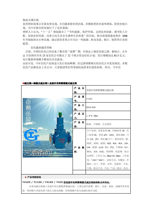
所以,今年信减压阀>>薄膜式减压阀>>直接作用弹簧薄膜式减压阀产品名称:直接作用弹簧薄膜式减压阀产品型号:Y410X产品口径:DN15-500产品压力:1.6-6.4Mpa产品材质:铸钢、不锈钢、合金钢等产品概括:生产标准:国家标准GB、机械标准JB、化工标准HG、美标API、ANSI、德标DIN、日本JIS、JPI、英标BS生产。
阀体材质:铜、铸铁、铸钢、碳钢、WCB、WC6、WC9、20#、25#、锻钢、A105、F11、F22、不锈钢、304、304L、316、316L、铬钼钢、低温钢、钛合金钢等。
工作压力1.0Mpa-50.0Mpa。
工作温度:-196℃-650℃。
连接方式:内螺纹、外螺纹、法兰、焊接、对焊、承插焊、卡套、卡箍。
驱动方式:手动、气动、液动、电动。
产品详细信息Y410X / Y110X / Y416X / Y42X型直接作用弹簧薄膜式减压阀结构特点和用处:本系列减压阀属于直接作用式薄膜弹簧减压阀。
主要由调节弹簧、膜片、活塞、阀座、阀瓣等零件组成。
一款具有独特抗磨剂系统的机械油,用于减少机械维护成本说明书

Customer benefitsMinimizes fleet maintenance costsUnique borate additive system significantly reduces friction, resulting in cooler operating temperatures, reduced wear and longer life of bearings and seals. Minimizes fleet operating costsOutstanding thermal and oxidation stability extends oil drain capability to morethan four times the length of conventional gear oils, even under extreme service conditions. Special low friction properties contribute to reduced fuel consumption. Extends equipment lifePatented borate EP technology creates an anti-wear film 3 to 5 times thicker than conventional EP additives, providing exceptional protection and longer gear life. Wide temperature range applicationExcellent low temperature flow properties and high temperature stability provide gear and bearing protection under a wide range of operating conditions. Applications• Heavy-duty non-synchronized manual transmissions, such as those manufactured by Eaton (Roadranger), ArvinMeritor and Mack.• Particularly recommended for heavy-duty road transport gearboxes exposed to extreme loads and temperatures.• Extended drain transmission oil applications in on-road heavy-duty equipmentProduct Data SheetProduct features:• Delo® Trans ESI®SAE 40 isa premium performance heavy-duty manual transmission lubricant.• Delo® Trans ESI®SAE 40is formulated with ISOSYN® Technology, a combinationof special base oils and a unique EP additive system incorporating inorganic borate technology, to provide oil life and wear protection far exceeding conventional gear oils underextreme service conditions.Delo® Trans ESI® SAE 40 Extended Drain Automotive Gear OilTypical key propertiesDELO® TRANS ESI® SAE40SAE Grade 40 Product Code 510092 Pour Pt, °C -33 Viscosity, mm²/s @40°Cmm²/s @ 100°C Viscosity Index 14414.5991401Performance standards• Suitable for use at extended drain intervals in Eaton (Roadranger®) and Meritor heavy-duty manual transmissions. ENVIRONMENT, HEALTH and SAFETYInformation is available on this product in the Material Safety Data Sheet (MSDS) and Customer Safety Guide. Customers are encouraged to review this information, follow precautions and comply with laws and regulations concern-ing product use and disposal. To obtain a MSDS for this product, visit:.Delo® Trans ESI® SAE 40Service ConsiderationsDelo® Trans ESI® SAE 40 is intended for use in heavy-duty non-synchronised manualtransmissions, such as those manufactured by Arvin Meritor, Mack and Roadranger. It is notrecommended for use in synchronized manual transmissions, or for use in any drive axles.Excessive in-service water contamination of Delo Trans ESI SAE 40 should be avoided. While itwill continue to provide excellent wear protection under such conditions, shortened seal lifemay result. Water contamination may be mitigated through operating or mechanical changes,for example the fitting of remote breather outlets to automotive gearboxes. However, ifexcessive water contamination cannot be avoided, another gear lubricant may provide a moreeffective solution and it is recommended that you consult your local Chevron representative.As for all Chevron borated gear oils, the recommended maximum storage life of Delo TransESI SAE 40 is 2 years from the date of manufacture. For best results, where containers havebeen stored for periods greater than 12 months, contents should be agitated (by stirring,rolling etc.) before use.This bulletin was prepared in good faithfrom the best information available atthe time of issue. While the valuesand characteristics are consideredrepresentative, some variation, not affectingperformance, can be expected. It is theresponsibility of the user to ensure that theproducts are used in the applications forwhich they are intended.Produced by:Chevron Lubricants- Asia Pacific。
4TNV88-SYY中文资料
rpm
2200
kW(PS)
27.1(36.8)
rpm
2200
N・m
130.4~142.1
说明
带风扇 不带风扇 带风扇
9 燃油消耗率 10 工作条件 11 空载怠速 12 调速性能
13 允许使用倾角 14 点火顺序 15 旋转方向 16 发动机重量 17 喷油正时 18 燃油系统
19 润滑系统
最高 最低 调速器型式 瞬态调速率 稳态调速率 恢复时间 稳定性 纵向 横向
校对
编制
发动机规格表G3-29642-源自430序号柴油机型号
1 型式
2 缸数-缸径×行程
3 喷油方式
4 压缩比
5 排量
6 额定功率(净功率)
7 额定功率(总功率)
8 最大扭矩(净扭矩)
4TNV88-SYY
四冲程直列水冷柴油机
mm
4-88×90
直喷
19.1
litter
1.116
kW(PS)
25.2(34.3)
25 发电机 26 发动机颜色 27 排放标准
启动机 蓄电池 冷启动装置
不带 0.9 8-410 2.7
5寸双滤芯
闭式
170 x L453
12V-2.3kW 80hA,CCA622 400W进气加热器
12V-40A 黑色
G3-29642-0430
进气阻力 2.94KPa (300mmq) 排气背压 12.74KPa (1300mmq) 推荐
燃油类别 喷油泵 喷油嘴 燃油滤清器 型式 机油等级 机油泵 机油滤清器
机油容量
机油压力
rpm
g/kW-h(g/PS-h)
rpm rpm
NAMUR接口1 4英寸和1 2英寸高流气动阀G1 4英寸和G1 2英寸用于控制空气驱动器应用说明书

aerospace climate control electromechanical filtrationfluid & gas handling hydraulics pneumatics process control sealing & shieldingD2D1"2""4"MFTD4D3Ra 3.2Description of ApplicationsControl of single or double acting pneumatic actuators, in safe or dangerous areas.NAMUR Interfaces 1/4" & 1/2"Th e interface design is conform to the NAMURstandard and to the VDI/VDE 3845 recommendations of the actuator industry. It allows a compact design of the actuator/valve unit. In case of a 3/2 function,the air of the actuator spring chamber also fl owsthrough the pilot valve (re-breather function).Th is prevents corrosion of the actuator springs.Market DescriptionProcess industriesChemical, Petrochemical industries Oil & GasWater & Sewage Pulp & Paper Food & BeveragePharmaceutical industryPowder Dosing-Transportation Air DryersF T D1 D2 D3 D4 min. M mm mm mm Mm mm M5 1/4 32 24 8 12 M5 M6 1/2 45 40 10 16 M6F: 2 mounting holes - T: 2 actuators control port - M: 2 holes for dowel pins● High fl ow: 1.250 l/min (1/4"), 3.000 l/min (1/2")● Compact design ● Long life expectancy● N3x series compatible with any Parker Lucifer coil(ATEX or not) of electrical group 2 (8/9 W coils)● Fail safe standard● Reduced inventory (3/2 & 5/2 functions with the samevalve on 341Nx5 series)● Mechanical part of the valve ATEX certifi ed accordingstandard EN 13463-1 & -5Function: 3/2 , 5/2, 3/2 <=> 5/2 and 5/3 valves.Manual override: Standard on all versions.Design: Solenoid operated spool valve with combined spring and air return & external air pressure operated versions.Mounting:For direct mounting on NAMUR interface ¼" & ½".Mounting position: I ndifferent.Material specifi cations: Aluminium body. Internal parts from stainless steel.Sealing material from NBR.Range of admissible pressure drop: Δp min. = see table. Δp max. = 10 bar.Media:Dry or lubricated air.Fluid temperature: Min. 0°C Max. + 50°C Ambient temperature: -10°C to +50°CElectrical part: N0x series are compatible with 22mm coil 496131 / 496482 / 496637 SeriesN3x series are compatible with 32/37/40 mm coils part of electrical group 2 (8/9W), including 481865 / 495870 / 495905 Series.Solenoid duty: 100% ED.Voltage: 481865 coil: 12 VDC , 24 VDC , 48 VDC , 110VDC, 24 V / 50 AC, 48 V / 50 AC,110 V / 50 AC, 220-230V/50 AC, 115 V / 60 Hz AC, 230 V / 60 AC.Voltage tolerance: ± 10% of nominal for 481865 coil.Class of insulation material: Class F for 481865 coil.Standards:Mechanical ATEX conform to EN 13463-1 & -5.Customer Value PropositionGeneral Information1313135135135135135G1/4" SeriesSolenoid Operated VersionsN03-N05 Series with 22 mm Coil3/2 Solenoid operated - Combined spring & air return (monostable)1/4 7 1250 2.5 10 10 50 NBR 331N03 - 496131 3 3 300 11/4 7 1250 2.5 10 10 50 NBR 331N03 - 496482 3 3 300 11/4 7 1250 2.5 10 10 50 NBR 331N03 - 496637 3 3 30015/2 Solenoid operated - Combined spring & air return (monostable)1/4 7 1250 2.5 10 10 50NBR 341N03 - 496131 3 3 300 21/4 7 1250 2.5 10 10 50 NBR 341N03 - 496482 3 3 300 2 1/47 1250 2.5 10 1050NBR 341N03 - 496637 3 3 30023/2 <=> 5/2 with conversion plate - Solenoid operated Combined spring & air return (monostable)1/4 7 1250 2.5 10 10 50NBR 341N05 - 496131 3 3 310 3 1/4 7 1250 2.5 10 10 50 NBR 341N05 - 496482 3 3 310 3 1/47 1250 2.5 10 1050NBR 341N05 - 496637 3 3 31035/2 Solenoid operated and return (bistable)1/47 1250 2.5 10 10 50NBR 347N03 - 496131 3 3 430 41/4 7 1250 2.5 10 10 50 NBR 347N03 - 496482 3 3 430 4 1/47 1250 2.5 10 1050NBR 347N03 - 496637 3 3 43045/3 W1 closed in center position - Solenoid operated and return1/4 7 1250 2.5 10 10 50NBR 342N03 - 496131 3 3 430 41/4 7 1250 2.5 10 10 50 NBR 342N03 - 496482 3 3 430 4 1/47 1250 2.5 10 1050NBR 342N03 - 496637 3 3 43045/3 W3 exhausted in center position Solenoid operated and return (bistable)1/4 7 1250 2.5 10 10 50NBR 343N03 - 496131 3 3 430 41/4 7 1250 2.5 10 10 50 NBR 343N03 - 496482 3 3 430 4 1/47 1250 2.5 10 1050NBR 343N03 - 496637 3 3 4304Please consult the "How to Order" part at the end of each coil chapter.Dimensions Reference 3Dimensions Reference 4404040403232322222222232326767676767505050505013 13 13 13 13 13 13 13 44 44 44 222236.536.5G1/4" (2x)G1/4" (3x)G1/4" (3x)G1/4" (3x)M5M5M5M52323232336,52424242423232323868610290 121414101212344355513332227.27.27.27.2Dimensions Reference 1Dimensions Reference 2131351351352440403232879738381313 19.519.513132222 24243232DIN 43650ADIN 43650A G1/8"G1/8"2222 1001302323232324 24 14 12245533G1/4" (3x)G1/4" (3x)M5M52222327.27.5Solenoid Operated VersionsN33-N35 Series with 32 / 37 / 40 mm CoilAdmissible Max. admissible differential fl uidPort size Orifi ce Q N pressure temperatureSeat Reference Consumption Weight Elect. Dim. (bar) (ºC)disc number Power (g) Group Ref.(Watt) max. Min. = 0ºC G mm L/min min DC= AC~ Air & Valve Housing Coil DC AC Neutral gases3/2 <=> 5/2 with conversion plate - Solenoid operated Combined spring & air return (monostable)1/4 7 1250 2.5 10 10 50NBR 341N35 2995 481865 9 8 480 2 5 1/4 7 1250 2.5 10 10 50 NBR - 2995 495870 9 8 700 - 2 1/47 1250 2.5 10 1050NBR - - 495905 8 8 740 - 25/2 Solenoid operated and return (bistable)1/47 1250 2.5 10 10 50NBR 347N33 2995 481865 9 8 750 2 6 1/4 7 1250 2.5 10 10 50 NBR - 2995 495870 9 8 1190 2 - 1/47 1250 2.5 10 1050NBR - - 495905 8 8 1270 2 -5/3 W1 closed in center positionSolenoid operated and return (bistable)1/4 7 1250 2.5 10 10 50NBR 342N33 2995 481865 9 8 750 2 6 1/4 7 1250 2.5 10 10 50 NBR - 2995 495870 9 8 1190 2 - 1/47 1250 2.5 10 1050NBR - - 495905 8 8 1270 2 -Please consult the "How to Order" part at the end of each coil chapter.Dimensions Reference 5Dimensions Reference 61313513513540404032323213 13 13 13131344 22 22 22 22 86868623232323232324 24 24 355133G1/4" (2x)G1/4" (3x)G1/4" (3x)G1/8G1/8G1/8M5M5M52222227.27.27.2External Pressure Air Operated Series 5xx N03 SeriesAdmissible Max. admissible differential fl uidPort size Orifi ce Q N pressure temperatureSeat Reference Consumption Weight Dimensions (bar) (ºC)disc number Power (g) Reference(Watt) max. Min. = 0ºC G mm L/min min DC= AC~ Air & Valve Housing Coil DC AC Neutral gases3/2 External pressure air operatedCombined spring & air return (monostable)External pressure supply 2.5 to 10 bar1/4 7 1250 2.5 10 10 50 NBR 531N03 - w/o - - 21075/2 external pressure air operatedCombined spring & air return (monostable)External pressure supply 2.5 to 10 bar1/47 1250 2.5 10 1050NBR 541N03 - w/o - - 21085/2 external pressure air operatedExternal pressure air return (bistable)External pressure supply 2.5 to 10 bar1/47 1250 2.5 10 1050NBR 547N03 - w/o - - 24095/3 W1 closed in center position - External pressure air operatedExternal pressure air return (bistable)External pressure supply 2.5 to 10 bar1/47 1250 2.5 10 1050NBR 542N03 - w/o - - 2409Dimensions Reference 7Dimensions Reference 8Dimensions Reference 913135135Solenoid Operated VersionsN34 Series with 32 / 37 / 40 mm CoilAdmissible Max. admissible differential fl uidPort size Orifi ce Q N pressure temperatureSeat Reference Consumption Weight Elect. Dim. (bar) (ºC)disc number Power (g) Group Ref.(Watt) max. Min. = 0ºC G mm L/min min DC= AC~ Air & Valve Housing Coil DC AC Neutral gases3/2 Solenoid operatedCombined spring & air return (monostable)1/2 12 3000 2.5 10 10 50NBR 331N34 2995 481865 9 8 910 2 10 1/2 12 3000 2.5 10 10 50 NBR - 2995 495870 9 8 1130 2 - 1/212 3000 2.5 10 1050NBR - - 495905 8 8 1170 2 -5/2 Solenoid operatedCombined spring & air return (monostable)1/2 12 3000 2.5 10 10 50NBR 341N34 2995 481865 9 8 900 2 11 1/2 12 3000 2.5 10 10 50 NBR - 2995 495870 9 8 1120 2 - 1/212 3000 2.5 10 1050NBR - - 495905 8 8 1160 2 -5/2 Solenoid operated and return (bistable)1/212 3000 2.5 10 10 50NBR 347N34 2995 481865 9 8 1240 2 12 1/2 12 3000 2.5 10 10 50 NBR - 2995 495870 9 8 1680 2 - 1/212 3000 2.5 10 1050NBR - - 495905 8 8 1760 2 -Please consult the "How to Order" part at the end of each coil chapter.Dimensions Reference 10Dimensions Reference 11Dimensions Reference 1213135External Pressure Air Operated Series5 xx N04 SeriesAdmissible Max. admissibledifferential fl uidPortsize Orifi ce QNpressure temperatureSeat ReferenceConsumptionWeightDimensions(bar)(ºC)disc number Power (g)Reference(Watt)max. Min. = 0ºCG mm L/min min DC= AC~ Air & Valve Housing Coil DC ACNeutralgases3/2 External pressure air operatedCombined spring & air return (monostable)External pressure supply 2.5 to 10 bar1/2 1230002.510 10 50 NBR531N04 - w/o - - 620 135/2 external pressure air operatedCombined spring & air return (monostable)External pressure supply 2.5 to 10 bar1/2 12 3000 2.5 10 10 50 NBR541N04 - w/o - - 600 14 Dimensions Reference 13Dimensions Reference 14● Power: 3W● Insulation Class: F (155°C)● Degree of Protection: IP65 (with plug)● Duty Cycle: 100% ED ●Ambient Temperature:-10°C to 50°C3 different types are available:● Ref. 496131for a safe area without plug ● Ref. 496482for a safe area with plug ● Ref. 496637for an ATEX area Zone 22Coils and Spare Parts Informations 496637 coil series with connection 2P + G when mounted together with the supplied Pg9 plug (delivered with the coil) are suitable for use in dangerous areas (dust Zone 22) according to the European directive ATEX 94/9/C. Protection mode: Ex tD A22 IP65 - T95°CAvailable Safe area Safe area ATEX Voltageswithout DIN plug with DIN plug Zone 22 EX II 3DOrder Order Order Code Code Code12VDC 496131 C1 496482 C1 496637 C124VDC 496131 C2 496482 C2 496637 C2 48VDC 496131 C4 496482 C4 496637 C4 110VDC 496131 C5 496482 C5 496637 C5 24/50-60VAC 496131 P0 496482 P0 496637 P0 48/50-60VAC 496131 S4 496482 S4 496637 S4 110/50-60VAC 496131 P2 496482 P2 496637 P2 115/60VAC 496131 K8 496482 K8 496637 K8230/50-60VAC 496131 P9496482 P9496637 P9How to OrderThe housing kit is already included into the coil reference, so it’s not needed to add it in the order code:Valve Reference Number - Coil Reference - Voltage code = Order codeExample: 341N03 - 496131 C2Valves and coils may be ordered also separately.Coils 22 mm for N03-N05 SeriesSafe Area & ATEX Zone 22 Ref. 496131 / 496482 / 496637Th ese coils with connection for 2 P+G DIN 43650 B plug are encapsulated in synthetic material, conform to the IEC/CENELEC safety standards and comply with European low voltage directive73/23/EC .S a f e A r e a & A T E X Z o n e 22● Power: 8W (AC) 9W (DC)● Insulation Class: F (155°C)● Degree of Protection: IP65 (with plug)● Duty Cycle: 100% ED● Voltage Tolerance -10%/+10%● Ambient Temperature -40°C/+50°C◗ The application can be limited alsoby the temperature range of the valveAvailable Order Voltages Code 12VDC 481865 C1 24VDC 481865 C2 48VDC 481865 C4 110VDC 481865 C5 24/50VAC 481865 A2 48/50VAC 481865 A4 110/50VAC 481865 A5 220-230/50VAC 481865 3D 380/50VAC 481865 A9 24/60VAC 481865 B2 115/60VAC 481865 K8 230/60VAC481865 J3How to OrderThis coil must be used together with a housing kit which includes a nut, a plate, and a washer. Housing Kit Order Code: 2995Valve Reference Number - Housing Reference - Coil Reference - Voltage Code = Order CodeExample: 341N35 - 2995 - 481865 C2Coils 32 mm / 37 mm / 40 mm for N33-N34-N35 Series Safe Area Ref. 481865N3x series are compatible with any Parker Lucifer coil part of electrical group 2. Th at group includes many diff erent coils for safe areas or areas submitted to ATEX certifi cations. Th ese coils are of the 8/9W class. Th ese coils with connection for 2P+G DIN 43650 A plug are encapsulated in synthetic material, conform to the IEC/CENELEC safety standards and comply with European low voltage directive 73/23/EC.S a f e A r e adtCoils and Spare Parts Informations ●Power: 8W● Insulation Class: F (155°C)● Degree of Protection: IP67 (with 4538 housing)● Duty Cycle: 100%●Voltage Tolerance -10%/+10%● Ambient Temperature -40°C/+50°C ◗ The application can be limited alsoby the temperature range of the valveHow to OrderValve Reference Number - Housing Reference - Coil Reference - Voltage Code = Order CodeExample: 331N34 - 4538 - 481000C2Housing 4538This enclosure is dust and water proof. It corresponds to the protection degree IP67 according to IEC/EN60529. Corrosion resistant, the metallic housing offers good protection for the coil against shocks. It can be 360° orientable. This housing must be equipped with 481000 series coil.Material: galvanized passivated steel - Degree of protection IP67 according to IEC/EN 60529 - Electrical connection: cable connection by cable gland according to DIN46320. Cable with outer diameter 6.5-13.5 mm (M20x1.5) can be simply sealed using a rubber gland resilient sealing rings. The enclosure is internally and externally fi tted with grounding and earthing screw terminals.Coils 32 mm / 37 mm / 40 mm for N33-N34-N35 Series Safe Area Coil 481000 Series with 4538 Watertight and dust proof housing IP67 Ref. 481000Coil 481000 series is encapsulated in synthetic material. Electrical connection is made with screw terminals for wire up to 1.5 mm. Th is coil conforms to the IEC/CENELEC safety standards and complies with European low voltage directive 73/23/EC. It must be used with a metallic housing.S a f e A r e a●II 3 G - Ex nAC IIC T3 / T4● II 3 D - Ex tD A22 IP65 - T 195°C / T 130°C● Power: 8W (AC) 9W (DC)● Insulation Class: F (155°C)● Degree of Protection: IP65 (with plug)● Duty Cycle: 100% ED● Voltage Tolerance -10%/+10%●Ambient temperature◗ T3 (gaz) T 195°C (dust) -40°C/+65°C ◗ T4 (gaz) T 130°C (dust) -40°C/+50°C◗ The application can be limited alsoby the temperature range of the valveAvailable Order Voltages Code 24VDC 495870 C2 48VDC 495870 C4 110VDC 495870 C5 24/50VAC 495870 A2 48/50VAC 495870 A4 110/50VAC 495870 A5 220-230/50VAC495870 3DA T E X Z o n e 2-22How to OrderThis coil must be used together with a housing kit which includes a nut, a plate, and a washer. Housing kit order code: 2995Valve Reference Number - Coil Reference - Voltage code = Order codeExample: 331N34 - 2995 - 495870 A5Coils 32 mm / 37 mm / 40 mm for N33-N34-N35 Series ATEX Zone 2-22 Ref. 495870Th is coil with connection 2P+G - when mounted together with the supplied Pg 9 plug (delivered with the coil), is suitable for use in Gas and Dust dangerous areas (Zone 2-22), according to the European directive ATEX 94/9/C . Certifi cate LCIE 05 ATEX 6003 X - Protection mode: non sparking / limited energy solenoid0081II 3 G-DA T E X z o n e 1-21●II 2 G - Ex d mb IIC T4● II 2 D - Ex tD A21 IP67 - T 130°C● Insulation Class H (180°C)● Power: 8W (AC-DC)● Degree of Protection IP67● Duty Cycle 100%● Voltage Tolerance -10%/+10%● Ambient Temperature: -40°C/+65°C◗ The application can be limited alsoby the temperature range of the valveAvailable Order Voltages Code 24VDC 495905 C2 48VDC 495905 C4 110VDC 495905 C5 24/50VAC 495905 A2 48/50VAC 495905 A4 110/50VAC 495905 E5 220-230/50VAC 495905 3D115/60 495905 E5240/60 495905 B8Electric connection is done in the connection box on an easily accessible connector terminals.M20x1.5 Cable glandHow to OrderThe housing kit is already included into the coil reference, so it’s not needed to add it in the order code:Valve Reference Number - Coil Reference - Voltage code = Order codeExample: 347N33 - 495905 C2Coils 32 mm / 37 mm / 40 mm for N33-N34-N35 Series ATEX Zone 1-21 Ref. 495905Th is coil is suitable for use in Gas and Dust dangerous areas (Zone 1-21), according to the European directive ATEX 94/9/C . It’s also IECEx certifi ed according to the IECEx Scheme. Certifi cate LCIE 02 ATEX 6451 X - Protection modes: Explosionproof solenoids with fl ameproof enclosure / encapsulation "d mb"0081II 2 G/Dnct c io o n n bo ox al a l s.s .Available OrderOrder Voltages Code Code 6VDC 483371 C0 - 12VDC 483371 C1 - 24VDC 483371 C2 494040 C236VDC 483371 C3 - 48VDC 483371 C4 - 60VDC 483371 M3 - 110VDC 483371 C5 - 125VDC 483371 3N 494040 3N 220VDC 483371 C7 494040 C712/50VAC 483371 A1 - 24/50VAC 483371 A2 494040 A248/50VAC 483371 A4 - 110-115/50VAC 483371 OA 494040 OA 220-230/50 483371 3D 494040 3D24/60VAC 483371 B2 - 110-115/60VAC 483371 6J - 220-240/60VAC 483371 4K-380/50-440/60VAC -494040 5PHow to OrderThe housing kit is already included into the coil reference, so it’s not needed to add it in the order code:Valve Reference Number - Coil Reference - Voltage code = Order codeExample: 347N33 - 483371C2Coils 32 mm / 37 mm / 40 mm for N33-N34-N35 Series ATEX Solutions Zone 1-21 Ref. 483371 & 494040Th ese coils are suitable for use in Gas and Dust dangerous areas (Zone 1-21), according to the European directive ATEX 94/9/C. Protection mode:encapsulated electrical parts with increased safety.483371…DC: 24V / 400mA - 48V / 250mA 110V / 100mAAC: 24V / 630mA - 48V / 315mA 110/115V / 160mA 220/230V / 80mA494040…DC: 24V / 400mA - 125V / 80mA48V /220V - 63mAAC: 24V / 630mA - 48V / 315mA 110/115V / 160mA220/230V / 80mAA T E X Z o n e 1-21Reference 483371 or HZ06 494040 or HZ23Approval LCIE 02 ATEX 6011 X LCIE 02 ATEX 6013 X Type of Gas II 2 G - Ex e mb II T4 II 2 G - Ex e mb II T3 II 2 G - Ex e mb II T4 protection Dust II 2 D - Ex tD A21 T 130°C II 2 D - Ex tD A21 T 195°C II 2 D - Ex tD A21 T 130°C Degree of protection I P67 I P67 Ambiant temperature -40°C to +65°C -40°C to +90°C -40°C to +65°CThe application is limited also by the temperature range of the valveClass of insulation F (155°) H (180°) Electrical connection By special cable gland or M20x1.5 "Ex e" on screw terminals for wires up to 1.5 mm². Cables with outside diameter 6.5 mm to 13.5 mm can be simply sealed using the rubber gland with resilient sealing rings supplied. Elect. DC Pn (hot) 8 W 8 W Power P (cold) 20°C 9 W 9 W AC Pn (holding) 8 W 8 W 32 VA (9 W) 32 VA (9 W) Voltage tolerance Tolerance -10/ +10% of the nominal voltageSolenoid duty Continuous duty solenoid (ED 100%)Fuses: Both electrical 483371… and 494040… parts have to be connected in series with asafety fuse according to CEI 60127-3.Spare Parts Mounting Kit and AccessoriesExhaust Flow RegulatorsMaterial Body: Brass Filter element: Sintered bronze Spring: Stainless Steel Seal: NBRG1/8" Order code: 496551 G1/4" Order code: 496552 G1/2" Order code: 496553Kit for G1/4" Modelswithout conversion plate (N x 3 Series)Kit includes the 2 mounting screws M5 x 25 A2, the dowel pin M5 x 10 A2, the 2 O-rings NBR 15 x 2.5Order code: 496132Kit for G1/2" Models (N x 4 Series)Kit includes the 2 mounting screws M6 x 35 A2, the dowel pin M6 x 12 A2, the 2 O-rings NBR 24 x 3Order code: 496133Kit for G1/4" Modelswith conversion plate (N x 5 Series)Kit includes the 2 mounting screws M5 x 35 A2, the dowel pin M5 x 20 A2,the conversion plate equipped with its seals Order code:496742Connector for 32 mm CoilConnector DIN43650 AA Pg9 2P+E Order code: 486586Housing for 22 mm CoilPlastic nut with O-ring Order code: 3125Connector for 22 mm CoilConnector DIN43650 AB Pg9 2P+E Order code:481043NotesAEROSPACEKey Markets• Aircraft engines• Business & general aviation• Commercial transports• Land-based weapons systems• Military aircraft• Missiles & launch vehicles• Regional transports• Unmanned aerial vehiclesKey ProductsFlight control systems& compon ntsFluid conveyance systemsFluid metering delivery& atomization devicesFuel systems & componentsHydraulic systems & componentsInert nitrogen generating systemsPneumatic systems & components• Wheels & brakesCLIMATE CONTROLKey MarketsAgricultureAir conditioningFood, beverage & dairy• Life sciences & medicalPrecision coolingProcessingTransportationKey ProductsCO2 controlsElectronic controllersFilter driersHand shut-off valvesHose & fi ttingsPressure regulating valvesRefrigerant distributorsSafety relief valvesSolenoid valvesThermostatic expansion valvesFILTRATIONKey MarketsFood & beverageIndustrial machineryLife sciencesMarineMobile equipmentOil & gasPower generationProcessTransportationKey ProductsAnalytical gas generatorsCompressed air & gas fi ltersCondition monitoringEngine air, fuel & oil fi ltration& syst msHydraulic, lubrication& coolant fi ltersProcess, chemical, water& microfi ltration fi ltersNitrogen, hydrogen & zeroair g n ratorsELECTROMECHANICALKey MarketsAerospaceFactory automationFood & beverageLife science & medicalMachine tools• Packaging machinery• Paper machinery• Plastics machinery & converting• Primary metalsSemiconductor & electronics• TextileWire & cableKey Products• AC/DC drives & systemsElectric actuatorsGearheadsHuman machine interfacesIndustrial PCs• InvertersLinear motors, slides and stagesPrecision stages• Stepper motorsServo motors, drives & controlsStructural extrusionsPNEUMATICSKey Markets• Aerospace• Conveyor & material handling• Factory automation• Food & beverage• Life science & medical• Machine tools• Packaging machinery• Transportation & automotiveKey ProductsAir preparationCompact cylindersField bus valve systemsGrippersGuided cylindersManifoldsMiniature fl uidicsPneumatic accessoriesPneumatic actuators & grippersPneumatic valves and controlsRodless cylindersRotary actuatorsTie rod cylindersVacuum generators, cups & sensorsFLUID & GAS HANDLINGKey MarketsAerospaceAgricultureBulk chemical handlingConstruction machineryFood & beverageFuel & gas deliveryIndustrial machineryMobileOil & gasTransportationWeldingKey ProductsBrass fi ttings & valvesDiagnostic equipmentFluid conveyance systemsIndustrial hosePTFE & PFA hose, tubing& plastic fi ttingsRubber & thermoplastic hose& couplingsTube fi ttings & adaptersQuick disconnectsHYDRAULICSKey Markets• Aerospace• Aerial lift• Agriculture• Construction machinery• Forestry• Industrial machinery• Mining• Oil & gas• Power generation & energy• Truck hydraulicsKey Products• Diagnostic equipment• Hydraulic cylinders& accumulators• Hydraulic motors & pumps• Hydraulic systems• Hydraulic valves & controls• Power take-offs• Rubber & thermoplastic hose& couplings• Tube fi ttings & adapters• Quick disconnectsPROCESS CONTROLKey MarketsChemical & refi ningFood, beverage & dairyMedical & dentalMicroelectronicsOil & gasPower generationKey ProductsAnalytical sample conditioningproducts & systemsFluoropolymer chemical deliveryfi ttings, valves & pumpsHigh purity gas delivery fi ttings,valves & regulatorsInstrumentation fi ttings, valves& r gulatorsMedium pressure fi ttings & valvesProcess control manifoldsSEALING & SHIELDINGKey MarketsAerospaceChemical processingConsumerEnergy, oil & gasFluid powerGeneral industrialInformation technologyLife sciencesMilitarySemiconductorTelecommunicationsTransportationKey ProductsDynamic sealsElastomeric o-ringsEMI shieldingExtruded & precision-cut,fabricated elastomeric sealsHomogeneous & insertedlastom ric shap sHigh temperature metal sealsMetal & plastic retainedcomposit s alsThermal management Parker’s Motion & Control TechnologiesAt Parker, we’re guidedby a relentless drive to helpour customers become moreproductive and achievehigher levels of profi tabilityby engineering the bestsystems for their require-ments. It means looking atcustomer applications frommany angles to fi nd newways to create value.Whatever the motion andcontrol technology need,Parker has the experience,breadth of product and globalreach to consistently deliver.No company knows moreabout motion and controltechnology than Parker.For further info call00800 27 27 5374.AE – UAE, Dubai Tel: +971 4 8127100********************AR – Argentina, Buenos Aires Tel: +54 3327 44 4129AT – Austria, Wiener Neustadt Tel: +43 (0)2622 23501-0*************************AT – Eastern Europe, Wiener NeustadtTel: +43 (0)2622 23501 900****************************AU – Australia, Castle Hill Tel: +61 (0)2-9634 7777AZ – Azerbaijan, Baku Tel: +994 50 2233 458****************************BE/LU – Belgium, Nivelles Tel: +32 (0)67 280 900*************************BR – Brazil, Cachoeirinha RS Tel: +55 51 3470 9144BY – Belarus, Minsk Tel: +375 17 209 9399*************************CA – Canada, Milton, Ontario Tel: +1 905 693 3000CH – Switzerland, Etoy Tel: +41 (0)21 821 87 00*****************************CL – Chile, Santiago Tel: +56 2 623 1216CN – China, Shanghai Tel: +86 21 2899 5000CZ – Czech Republic, Klecany Tel: +420 284 083 111*******************************DE – Germany, Kaarst Tel: +49 (0)2131 4016 0*************************DK – Denmark, Ballerup Tel: +45 43 56 04 00*************************ES – Spain, Madrid Tel: +34 902 330 001***********************FI – Finland, Vantaa Tel: +358 (0)20 753 2500parker.fi ****************FR – France, Contamine s/ArveTel: +33 (0)4 50 25 80 25************************GR – Greece, Athens Tel: +30 210 933 6450************************HK – Hong Kong Tel: +852 2428 8008HU – Hungary, Budapest Tel: +36 1 220 4155*************************IE – Ireland, Dublin Tel: +353 (0)1 466 6370*************************IN – India, MumbaiTel: +91 22 6513 7081-85IT – Italy, Corsico (MI)Tel: +39 02 45 19 21***********************JP – Japan, Tokyo Tel: +81 (0)3 6408 3901KR – South Korea, Seoul Tel: +82 2 559 0400KZ – Kazakhstan, Almaty Tel: +7 7272 505 800****************************LV – Latvia, Riga Tel: +371 6 745 2601************************MX – Mexico, Apodaca Tel: +52 81 8156 6000MY – Malaysia, Shah Alam Tel: +60 3 7849 0800NL – The Netherlands, OldenzaalTel: +31 (0)541 585 000********************NO – Norway, Ski Tel: +47 64 91 10 00************************NZ – New Zealand, Mt Wellington Tel: +64 9 574 1744PL – Poland, Warsaw Tel: +48 (0)22 573 24 00************************PT – Portugal, Leca da Palmeira Tel: +351 22 999 7360**************************RO – Romania, Bucharest Tel: +40 21 252 1382*************************RU – Russia, Moscow Tel: +7 495 645-2156************************SE – Sweden, Spånga Tel: +46 (0)8 59 79 50 00************************SG – Singapore Tel: +65 6887 6300SK – Slovakia, Banská Bystrica Tel: +421 484 162 252**************************SL – Slovenia, Novo Mesto Tel: +386 7 337 6650**************************TH – Thailand, Bangkok Tel: +662 717 8140TR – Turkey, Istanbul Tel: +90 216 4997081************************TW – Taiwan, Taipei Tel: +886 2 2298 8987UA – Ukraine, Kiev Tel +380 44 494 2731*************************UK – United Kingdom, WarwickTel: +44 (0)1926 317 878********************US – USA, Cleveland Tel: +1 216 896 3000VE – Venezuela, Caracas Tel: +58 212 238 5422ZA – South Africa,Kempton ParkTel: +27 (0)11 961 0700*****************************Parker WorldwideEuropean Product Information Centre Free phone: 00 800 27 27 5374(from AT, BE, CH, CZ, DE, EE, ES, FI, FR, IE, IL, IS, IT, LU, MT, NL, NO, PT, SE, SK, UK)E d . 2010-06-08Parker Hannifi n Ltd. Tachbrook Park DriveTachbrook Park, Warwick CV34 6TU United KingdomTel.: +44 (0) 1926 317 878Catalogue 1101/UK - 06/2010 - TMCZ© 2010 Parker Hannifi n Corporation.All rights reserved.。
TMP86FH46NG中文资料
♦Watchdog timer•Interrupt sources/reset output (Programmable)♦Serial interface•8-bit SIO:1ch•8-bit UART: 1 ch♦10-bit successive approximation type AD converter•Analog input: 8 ch♦Key-on wakeup: 4 ch♦Dual clock operation•Single/dual-clock mode♦Nine power saving operating modes•STOP mode:Oscillation stops. Battery/capacitor backup.Port output hold/high-impedance.•SLOW 1, 2 mode:Low power consumption operation using low-frequency clock (32.768 kHz)•IDLE 0 mode:CPU stops, and peripherals operate using high-frequency clock of time-base-timer. Release by INTTBT interrupt.•IDLE 1 mode:CPU stops, and peripherals operate using high-frequency clock.Release by interrupts.•IDLE 2 mode:CPU stops, and peripherals operate using high and low frequency clock.Release by interrupts.•SLEEP 0 mode:CPU stops, and peripherals operate using low-frequency clock of time-base-timer. Release by INTTBT interrupt.•SLEEP 1 mode:CPU stops, and peripherals operate using low-frequency clock.Release by interrupts.•SLEEP 2 mode:CPU stops, and peripherals operate using high and low frequency clock.Release by interrupts.♦Wide operating voltage:4.5 to 5.5 V at 16 MHz/32.768 kHz2.7 to 5.5 V at 8 MHz/32.768 kHzNote:The operating voltage, the operating temperature and the operating current are different between TMP86FH46 and TMP86C846/H46.About details, please refer to electrical characteristics of each products.Pin FunctionThe TMP86FH46 has MCU mode and serial PROM mode.(1)MCU modeIn the MCU mode, the TMP86FH46 is a pin compatible with the TMP86C846/H46 (Make sure to fix the TEST pin to low level).(2)Serial PROM modeThe serial PROM mode is set by fixing TEST pin, P10 and P11 at “high” respectively when RESET pin is fixed “low”.After release of reset, the built-in BOOT ROM program is activated and the built-in flash memory is rewritten by serial I/F (UART).Pin Name (Serial PROM mode)Input/OutputFunctionsPin Name(MCU mode)BOOT1/RXD Input/Input Fix “High” during reset. This pin is used asRXD pin after releasing reset.P10BOOT2/TXD Input/Output Fix “High” during reset. This pin is used asTXD pin after releasing reset.P11TEST Input Fix to “High”.RESET I/O Reset signal input or an internal error reset output.VDD, AVDDPower supply 5 VVSS, AVSS0 VVAREF Leave open or apply reference voltage.P07 to P00, P15 to P12, P22 to P20,P37 to P30, P47 to P40Fix to “Low” or “High”.XIN InputSelf oscillation with resonator (2 MHz, 4 MHz, 8 MHz, 16 MHz) XOUT Output1.1.2Data MemoryTMP86FH46 has a built-in 512-byte data memory (Static RAM).1.1.3Input/Output Circuitry(1)Control pinsThe control pins of the TMP86FH46 are the same as those of the TMP86C846/H46.(2)I/O portsThe I/O circuitries of TMP86FH46 I/O ports are the same as the those of TMP86C846/H46.2.4Interface Specifications for UARTThe following shows the UART communication format used in serial PROM mode.Before on-board programming can be executed, the communication format on the external controller side must also be setup in the same way as for this product.Note that although the default baud rate is 9,600 bps, it can be changed to other values as shown in Table 2.4.1. The Table 2.4.2 shows an operating frequency and baud rate in serial PROM mode. Except frequency which is not described in Table 2.4.2 can not use in serial PROM mode.Baud rate (Default): 9,600 bps Data length: 8 bits Parity addition: None Stop bit length: 1 bitTable 2.4.1 Baud Rate Modification DataTable 2.4.2 Operating Frequency and Baud Rate in Serial PROM ModeNote:“Reference Frequency” shows the high-frequency area supported in serial PROM mode.Except the above frequency can not be supported in serial PROM mode.2.5CommandThere are five commands in serial PROM mode. After reset release, the TMP86FH46 waits a matching data (5AH).Table 2.5.1 Command in Serial PROM ModeBaud rate modification data04H05H07H0AH18H28HBaud rate (bps)76800625003840031250192009600Reference BaudRate (Baud)76800625003840031250192009600Baud RateModification Data04H05H 07H 0AH 18H 28H Reference Frequency (MHz)(bps)(%)(bps)(%)(bps)(%)(bps)(%)(bps)(%)(bps)(%)2––––––––––9615+0.164––––––312500.0019231+0.169615+0.168––625000.0038462+0.16312500.0019231+0.169615+0.161676923+0.16625000.0038462+0.16312500.0019231+0.169615+0.16Command DataOperation ModeRemarks5AH SetupMatching data. Always start with this command after reset release. 30H Flash memory writingWriting to area from C000H to FFFFH is enable.60H RAM loader Writing to area from 0050H to 0230H is enable.90H Flash memory SUM output The checksum of entire flash memory area (from C000H to FFFFH)is output in order of the upper byte and the lower byte.C0HProduct discrimination code outputProduct discrimination code, that is expressed by 13 bytes data, is output.2.6Operation ModeThere are four operating modes in serial PROM mode: Flash memory writing mode, RAM loader mode, flash memory SUM output mode and product discrimination code output mode. For details about these modes, refer to (1) Flash memory writing mode through (4) Product discrimination code output mode.(1)Flash memory writing modeThe data are written to the specified flash memory addresses. The controller should send thewrite data in the Intel Hex format (Binary). For details of writing data format, refer to 2.7“Flash Memory Writing Data Format”.If no errors are encountered till the end record, the SUM of 16 Kbytes of flash memory iscalculated and the result is returned to the controller.To execute the flash memory writing mode, the TMP86FH46 checks the passwords except ablank product. If the passwords did not match, the program is not executed.(2)RAM loader modeThe RAM loader transfers the data into the internal RAM that has been sent from thecontroller in Intel Hex format. When the transfer has terminated normally, the RAM loadercalculates the SUM and sends the result to the controller before it starts executing the userprogram. After sending of SUM, the program jumps to the start address of RAM in which thefirst transferred data has been written. This RAM loader function provides the user's own wayto control on-board programming.To execute the RAM loader mode, the TMP86FH46 checks the passwords except a blankproduct. If the passwords did not match, the program is not executed.(3)Flash memory SUM output modeThe SUM of 16 Kbytes of flash memory is calculated and the result is returned to thecontroller.The BOOT ROM does not support the reading function of the flash memory. Instead, it hasthis SUM command to use. By reading the SUM, it is possible to manage Revisions ofapplication programs.(4)Product discrimination code output modeThe product discrimination code is output as a 13-byte data, that includes the start addressand the end address of ROM. (In case of TMP86FH46, the start address is C000H and the endaddress is FFFFH.) Therefore, the controller can recognize the device information by using thisfunction.2.6.1Flash Memory Writing Mode (Operation command: 30H)Table 2.6.1 shows flash memory writing mode process.Table 2.6.1 Flash Memory Writing Mode ProcessNote 1:“xxH × 3” denotes that operation stops after sending 3 bytes of xxH. For details, refer to 2.8“Error Code”.Note 2:Refer to 2.10 “Intel Hex Format (Binary)”.Note 3:Refer to 2.9 “Checksum (SUM)”.Note 4:Refer to 2.11 “Passwords”.Note 5:If all data of vector area are “00H” or “FFH”, the passwords comparison is not executedbecause the device is considered as blank product. However, it is necessary to specify the password count storage addresses and the password comparison start address even though it is a blank product. If a password error occurs, the UART function of TMP86FH46 stops without returning error code to the controller. Therefore, when a password error occurs, the TMP86FH46 should be reset by RESET pin input.Note 6:The time between data records needs over 1 ms.Number of Bytes TransferredTransfer Data from External Controller toTMP86FH46Baud RateTransfer Data from TMP86FH46 to ExternalControllerBOOT ROM1st byte 2nd byte Matching data (5AH)−9600 bps 9600 bps − (Baud rate auto set)OK: Echo back data (5AH)Error: Nothing transmitted 3rd byte 4th byteBaud rate modification data (See T able 2.4.1)−9600 bps 9600 bps−OK: Echo back dataError: A1H × 3, A3H × 3, 62H × 3(Note 1)5th byte 6th byte Operation command data (30H)−Changed new baud rate Changed new baud rate−OK: Echo back data (30H)Error: A1H × 3, A3H × 3, 63H × 3(Note 1)7th byte 8th byte Address 15 to 08 in which to store Password count (Note 4)Changed new baud rate Changed new baud rate −OK: Nothing transmitted Error: Nothing transmitted 9th byte 10th byteAddress 07 to 00 in which to store Password count (Note 4)Changed new baud rate Changed new baud rate −OK: Nothing transmitted Error: Nothing transmitted 11th byte 12th byte Address 15 to 08 in which to start Password comparison (Note 4)Changed new baud rate Changed new baud rate −OK: Nothing transmitted Error: Nothing transmitted 13th byte 14th byte Address 07 to 00 in which to start Password comparison (Note 4)Changed new baud rate Changed new baud rate −OK: Nothing transmitted Error: Nothing transmitted 15th byte :m'th byte Password string (Note 5)−Changed new baud rate Changed new baud rate −OK: Nothing transmitted Error: Nothing transmitted m'th + 1 byte :n'th − 2 byte Extended Intel format (binary)(Note 2, 6)Changed new baud rate−n'th − 1 byte −Changed new baud rate OK: SUM (High) (Note 3)Error: Nothing transmitted n'th byte −Changed new baud rate OK: SUM (Low) (Note 3)Error: Nothing transmitted n'th + 1 byte(Wait for the next operation)(Command data)Changed new baud rate−Description of flash memory writing mode1.The receive data in the 1st byte is the matching data. When the boot program starts in serialPROM mode, TMP86FH46 (Mentioned as “device” hereafter) waits for the matching data (5AH) to receive. Upon receiving the matching data, it automatically adjusts the UART’s initial baud rate to 9,600bps.2.When the device has received the matching data, the device transmits the data “5AH” as anecho back to the controller. If the device can not receive the matching data, the device does not transmit the echo back data and waits for the matching data again with changing baud rate.Therefore, the controller should send the matching data continuously until the device transmits the echo back data.3.The receive data in the 3rd byte is the baud rate modification data. The six kinds of baud ratemodification data shown in Table 2.4.1 are available. Even if baud rate changing is no need, be sure to send the initial baud rate data (28H: 9,600 bps). The changing of baud rate is executed after transmitting the echo back data.4.When the 3rd byte data is one of the baud rate modification data corresponding to the device'soperating frequency, the device sends the echo back data which is the same as received baud rate modification data. Then the baud rate is changed. If the 3rd byte data does not correspond to the baud rate modification data, the device stops UART function after sending3 bytes of baud rate modification error code: (62H).5.The receive data in the 5th byte is the command data (30H) to write the flash memory.6.When the 5th byte is one of the operation command data shown in Table 2.5.1, the devicesends the echo back data which is the same as received operation command data (in this case, 30H). If the 5th byte data does not correspond to the operation command data, the device stops UART function after sending 3 bytes of operation command error code: (63H).7.The 7th byte is used as an upper bit (Bit15 to bit8) of the password count storage address.When the receiving is executed correctly (No error), the device does not send any data. If the receiving error or password error occur, the device does not send any data and stops UART function.8.The 9th byte is used as a lower bit (Bit7 to bit0) of the password count storage address. Whenthe receiving is executed correctly (No error), the device does not send any data. If the receiving error or password error occur, the device does not send any data and stops UART function.9.The 11th byte is used as an upper bit (Bit15 to bit8) of the password comparison startaddress. When the receiving is executed correctly (No error), the device does not send any data. If the receiving error or password error occur, the device does not send any data and stops UART function.10.The 13th byte is used as a lower bit (Bit7 to bit0) of the password comparison start address.When the receiving is executed correctly (No error), the device does not send any data. If the receiving error or password error occur, the device does not send any data and stops UART function.11.The 15th through the m’th bytes are the password data. The number of passwords is the data(N) indicated by the password count storage address. The password data are compared for N entries beginning with the password comparison start address. The controller should send N bytes of password data to the device. If the passwords do not match, the device stops UART function without returning error code to the controller. If the data of vector addresses (FFE0H to FFFFH) are all “FFH”, the comparison of passwords is not executed because the device is considered as a blank product.12.The receive data in the m’th + 1 through n’th − 2 byte are received as binary data in Intel Hexformat. No received data are echoed back to the controller. The data which is not the start mark (3AH for “:”) in Intel Hex format is ignored and does not send an error code to the controller until the device receives the start mark. After receiving the start mark, the device receives the data record, that consists of length of data, address, record type, writing data and checksum. After receiving the checksum of data record, the device waits the start mark data (3AH) again. The data of data record is temporarily stored to RAM and then, is written to specified flash memory by page (32 bytes) writing. For details of an organization of flash memory, refer to 2. “Serial PROM Mode”. Since after receiving an end record, the device starts to calculate the SUM, the controller should wait the SUM after sending the end record. If receive error or Intel Hex format error occurs, the device stops UART function without returning error code to the controller.13.The n’th − 1 and the n’th bytes are the SUM value that is sent to the controller in order of theupper byte and the lower byte. For details on how to calculate the SUM, refer to 2.9“Checksum (SUM)”. The SUM calculation is performed after detecting the end record, but the calculation is not executed when receive error or Intel Hex format error has occurred. The time required to calculate the SUM of the 16 Kbytes of Flash memory area is approximately 100 ms at fc = 16 MHz. After the SUM calculation, the device sends the SUM data to the controller. After sending the end record, the controller can judge that the transmission has been terminated correctly by receiving the checksum.14.After sending the SUM, the device waits for the next operation command data.2.6.2RAM Loader Mode (Operation command: 60H)Table 2.6.2 shows RAM loader mode process.Table 2.6.2 RAM Loader Mode ProcessNote 1:“xxH × 3” denotes that operation stops after sending 3 bytes of xxH. For details, refer to 2.8“Error Code”.Note 2:Refer to 2.10 “Intel Hex Format (Binary)”.Note 3:Refer to 2.9 “Checksum (SUM)”.Note 4:Refer to 2.11 “Passwords”.Number of Bytes TransferredTransfer Data from External Controller toTMP86FH46Baud RateTransfer Data from TMP86FH46 to ExternalControllerBOOT ROM1st byte 2nd byte Matching data (5AH)−9600 bps 9600 bps − (Baud rate auto set)OK: Echo back data (5AH)Error: Nothing transmitted 3rd byte 4th byteBaud rate modification data (See Table 2.4.1)−9600 bps 9600 bps−OK: Echo back dataError:A1H × 3, A3H × 3, 62H × 3(Note 1)5th byte 6th byteOperation command data (60H)−Changed new baud rate Changed new baud rate−OK: Echo back data (60H)Error: A1H × 3, A3H × 3, 63H × 3(Note 1)7th byte 8th byte Address 15 to 08 in which to store Password count (Note 4)Changed new baud rate Changed new baud rate −OK: Nothing transmitted Error: Nothing transmitted 9th byte10th byte Address 07 to 00 in which to store Password count (Note 4)Changed new baud rate Changed new baud rate −OK: Nothing transmitted Error: Nothing transmitted 11th byte 12th byte Address 15 to 08 in which to start Password comparison (Note 4)Changed new baud rate Changed new baud rate −OK: Nothing transmitted Error: Nothing transmitted 13th byte 14th byte Address 07 to 00 in which to start Password comparison (Note 4)Changed new baud rate Changed new baud rate −OK: Nothing transmitted Error: Nothing transmitted 15th byte :m'th byte Password string (Note 5)−Changed new baud rate Changed new baud rate−OK: Nothing transmitted Error: Nothing transmitted m'th + 1 byte :n'th − 2 byte Extended Intel format (Binary)(Note 2)Changed new baud rate−n'th − 1 byte −Changed new baud rate OK: SUM (High) (Note 3)Error: Nothing transmitted n'th byte−Changed new baud rateOK: SUM (Low) (Note 3)Error: Nothing transmittedRAM−The program jumps to the start address of RAM in which the first transferred data has been written.Note 5:If all data of vector area are “00H” or “FFH”, the passwords comparison is not executed because the device is considered as blank product. However, it is necessary to specify the password count storage addresses and the password comparison start address even though it is a blank product. If a password error occurs, the UART function of TMP86FH46 stops without returning error code to the controller. Therefore, when a password error occurs, the TMP86FH46 should be reset by RESET pin input.Note 6:Do not send only end record after transferring of password string. If the TMP86FH46 receives the end record only after reception of password string, it does not operate correctly.Description of RAM loader mode1.The process of the 1st byte through the 4th byte are the same as flash memory writing mode.2.The receive data in the 5th byte is the RAM loader command data (60H) to write the user’sprogram to RAM.3.When the 5th byte is one of the operation command data shown in Table 2.5.1, the devicesends the echo back data which is the same as received operation command data (in this case, 60H). If the 5th byte data does not correspond to the operation command data, the device stops UART function after sending 3 bytes of operation command error code: (63H).4.The process of the 7th byte through the m’th byte are the same as flash memory writingmode.5.The receive data in the m’th + 1 through n’th − 2byte are received as binary data in Intel Hexformat. No received data are echoed back to the controller.The data which is not the start mark (3AH for “:”) in Intel Hex format is ignored and does not send an error code to the controller until the device receives the start mark. After receiving the start mark, the device receives the data record, that consists of length of data, address, record type, writing data and checksum. After receiving the checksum of data record, the device waits the start mark data (3AH) again. The data of data record is written to specified RAM by the receiving data. Since after receiving an end record, the device starts to calculate the SUM, the controller should wait the SUM after sending the end record. If receive error or Intel Hex format error occurs, the UART function of TMP86FH46 stops without returning error code to the controller.6.The n’th − 1 and the n’th bytes are the SUM value that is sent to the controller in order of theupper byte and the lower byte. For details on how to calculate the SUM, refer to 2.9“Checksum (SUM)”. The SUM calculation is performed after detecting the end record, but the calculation is not executed when receive error or Intel Hex format error has occurred.The SUM is calculated by the data written to RAM, but the length of data, address, record type and checksum in Intel Hex format are not included in SUM.7.The boot program jumps to the first address that is received as data in Intel Hex format aftersending the SUM to the controller.2.6.3Flash Memory Memory SUM Output Mode (Operation command: 90H)Table 2.6.3 shows flash memory SUM output mode process.Table 2.6.3 Flash Memory Memory SUM Output ProcessNote 1:“xxH × 3” denotes that operation stops after sending 3 bytes of xxH. For details, refer to 2.8“Error Code”.Note 2:Refer to 2.9 “Checksum (SUM)”Description of flash memory SUM output mode 1.The process of the 1st byte through the 4th byte are the same as flash memory writing mode.2.The receive data in the 5th byte is the flash memory SUM command data (90H) to calculate the entire flash memory.3.When the 5th byte is one of the operation command data shown in Table 2.5.1, the device sends the echo back data which is the same as received operation command data (in this case,90H). If the 5th byte data does not correspond to the operation command data, the device stops UART function after sending 3 bytes of operation command error code: (63H).4.The 7th and the 8th bytes are the SUM value that is sent to the controller in order of the upper byte and the lower byte. For details on how to calculate the SUM, refer to 2.9“Checksum (SUM)”.5.After sending the SUM, the device waits for the next operation command data.Number of Bytes TransferredTransfer Data from External Controller toTMP86FH46Baud RateTransfer Data from TMP86FH46 to ExternalControllerBOOT ROM 1st byte 2nd byte Matching data (5AH)−9600 bps 9600 bps − (Baud rate auto set)OK: Echo back data (5AH)Error: Nothing transmitted 3rd byte 4th byteBaud rate modification data (See Table 2.4.1)−9600 bps 9600 bps−OK: Echo back dataError: A1H × 3, A3H × 3, 62H × 3(Note 1)5th byte 6th byteOperation command data (90H)−Changed new baud rate Changed new baud rate−OK: Echo back data (90H)Error: A1H × 3, A3H × 3, 63H × 3(Note 1)7th byte −Changed new baud rate OK: SUM (High) (Note 2)Error: Nothing transmitted 8th byte −Changed new baud rate OK: SUM (Low) (Note 2)Error: Nothing transmitted 9th byte(Wait for the next operation)(Command data)Changed new baud rate−2.6.4Product Discrimination Code Output Mode (Operation command: C0H)Table 2.6.4 shows product discrimination code output mode process.Table 2.6.4 Product Discrimination Code Output ProcessNote:“xxH × 3” denotes that operation stops after sending 3 bytes of xxH. For details, refer to 2.8“Error Code”.Description of product discrimination code output mode 1.The process of the 1st byte through the 4th byte are the same as flash memory writing mode.2.The receive data in the 5th byte is the product discrimination code output command data (C0H).3.When the 5th byte is one of the operation command data shown in Table 2.5.1, the device sends the echo back data which is the same as received operation command data (in this case,C0H). If the 5th byte data does not correspond to the operation command data, the device stops UART function after sending 3 bytes of operation command error code: (63H).4.The 9th and the 19th bytes are the product discrimination code. For details, refer to 2.12“Product Discrimination Code”.5.After sending the SUM, the device waits for the next operation command data.Number of Bytes TransferredTransfer Data from External Controller toTMP86FH46Baud RateTransfer Data from TMP86FH46 to ExternalControllerBOOT ROM1st byte 2nd byte Matching data (5AH)−9600 bps 9600 bps − (Baud rate auto set)OK: Echo back data (5AH)Error: Nothing transmitted 3rd byte 4th byteBaud rate modification data (See Table 2.4.1)−9600 bps 9600 bps−OK: Echo back dataError: A1H × 3, A3H × 3, 62H × 3(Note 1)5th byte 6th byteOperation command data (C0H)−Changed new baud rate Changed new baud rate−OK: Echo back data (C0H)Error: A1H × 3, A3H × 3, 63H × 3(Note 1)7th byte Changed new baud rate 3AH Start mark 8th byteChanged new baud rate 0AH The number of transferdata (from 9th to 18th byte)9th byte Changed new baud rate 02H Length of address (2 bytes)10th byte Changed new baud rate 03H Reserved data 11th byte Changed new baud rate 00H Reserved data 12th byte Changed new baud rate 00H Reserved data 13th byte Changed new baud rate 00H Reserved data 14th byte Changed new baud rate 01H The number of ROM block(1 block)15th byte Changed new baud rate C0H First address of ROM(Upper 8 bits)16th byte Changed new baud rate 00H First address of ROM(Lower 8 bits)17th byte Changed new baud rate FFH End address of ROM(Upper 8 bits)18th byte Changed new baud rate FFH End address of ROM(Lower 8 bits)19th byte Changed new baud rate 3CH Checksum of transferreddata (from 9th to 18th byte)20th byte(Wait for the next operation)(Command data)Changed new baud rate−2.8Error CodeWhen the device detects an error, the error codes are sent to the controller.Table 2.8.1 Error Code2.9Checksum (SUM)(1)Calculation methodSUM consists of byte + byte.... + byte, the checksum of which is returned in word as the result.Namely, data is read out in byte and checksum of which is calculated, with the result returned in word.Example:The SUM returned when executing the flash memory write command, RAMloader command, or flash memory SUM command is calculated in the manner shown above.(2)Calculation dataThe data from which SUM is calculated are listed in Table 2.9.1 below.Table 2.9.1 Checksum Calculation DataTransmit DataMeaning of Transmit Data62H, 62H, 62H Baud rate modification error occurred.63H, 63H, 63H Operating command error occurred.A1H, A1H, A1H Framing error in received data occurred.A3H, A3H, A3HOverrun error in received data occurred.A1H If the data to be calculated consists of the four bytes shown to the left, SUM of the data isB2H A1H + B2H + C3H + D4H =02EAHSUM (HIGH)=02H SUM (LOW)=EAH C3H D4HOperating ModeCalculation Data RemarksFlash memory writing modeData in the entire area (16 Kbytes) of flashmemoryEven when written to part of the flash memory area,data in the entire memory area (16 Kbytes) iscalculated.The length of data, address, record type andchecksum in Intel Hex format are not included in SUM.Flash memory Checksum output modeRAM loader mode Data written to RAMThe length of data, address, record type andchecksum in Intel Hex format are not included in SUM.Product discrimination code out-put mode Checksum of transferred data (from 9th to 18th byte)For details, refer to “2.6.4 Product Discrimination Code Output Mode”.。
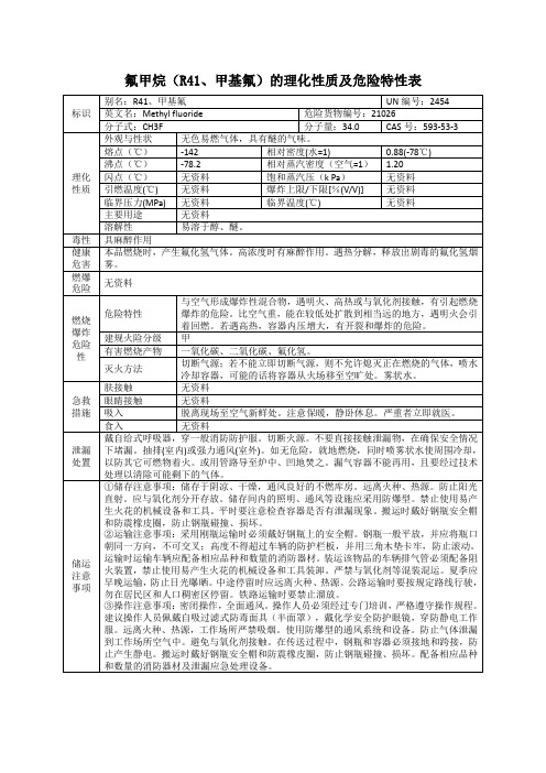
氟甲烷(R41、甲基氟)的理化性质及危险特性表
无资料
燃烧爆炸危险性
危险特性
与空气形成爆炸性混合物,遇明火、高热或与氧化剂接触,有引起燃烧爆炸的危险。比空气重,能在较低处扩散到相当远的地方,遇明火会引着回燃。若遇高热,容器内压增大,有开裂和爆炸的危险。
建规火险分级
甲
有害燃烧产物
一氧化碳、二氧化碳、氟化氢。
灭火方法
切断气源;若不能立即切断气源,则不允许熄灭正在燃烧的气体,喷水冷却容器,可能的话将容器从火场移至空旷处。雾状水。
氟甲烷(R41、甲基氟)的理化性质及危险特性表
标识
别名:R41、甲基氟
UN编号:2454
英文名:Methyl fluoride
危险货物编号:21026
分子式:CH3F
分子量:34.0
CAS号:593-53-3
理化性质
外观与性状
无色易燃气体,具有醚的气味。
熔点(℃)
-142
相对密度(水=1)
0.88(-78℃)
急救
措施
肤接触
无资料
眼睛接触
无资料
吸入
脱离现场至空气新鲜处。注意保暖,静卧休息。严重者立即就医。
食入
无资料
泄漏处置
戴自给式呼吸器,穿一般消防防护服。切断火源。不要直接接触泄漏物,在确保安全情况下堵漏。抽排(室内)或强力通风(室外)。如无危险,就地燃烧,同时喷雾状水使周围冷却,以防其它可燃物着火。或用管路导至炉中、凹地焚之。漏气容器不能再用,且要经过技术处理以清除可能剩下的气体。
储运注意事项
①储存注意事项:储存于阴凉、干燥,通风良好的不燃库房。远离火种、热源。防止阳光直射。应与氧化剂分开存放。储存间内的照明、通风等设施应采用防爆型。禁止使用易产生火花的机械设备和工具。平时要注意检查容器是否有泄漏现象。搬运时戴好钢瓶安全帽和防震橡皮圈,防止钢瓶碰撞、损坏。
GfG G888C G888M 产品技术规格说明书
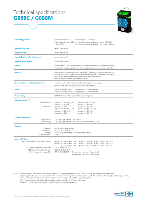
Technical specifications: G888C / G888M © GfG - 2021 | All information in this data sheet is subject to technical changes due to further development.Measuring principle Electrochemical (EC): for toxic gases and oxygen Catalytic combustion (CC): for flammable gases and vapors (up to 100%LEL)Infrared (IR): for flammable gases and vapors and carbon dioxideMeasuring ranges sensor dependentResponse time sensor dependentExpected average life of the sensor sensor dependentMeasuring gas supply via diffusion modeDisplay illuminated LCD full graphics display, automatic size setting for optimum reading, displays the battery capacity, gas concentration as current value and peak valueAlerting depending on the gas type 3 or 2 momentary value and 2 exposure level alarms, battery alarm with visual and acoustical signaling as well as display on the screen, color of the display depending on the alarm state (orange/red). Horn: 103 dB(A) (can be reduced to 90 dB(A))Zero point and sensitivity adjustment manual or automatic with an adjustment program, if necessary, test gas supply via the “SMART CAP” with 0.5...0.6slpmRadio optional 868MHz for EU; range approx. 700 m (free field)optional 915MHz for USA; range approx. 300 m (free field)Power supply NiMH battery module; 2,6V 2100mAh; rechargeableOperating time (*1)without Radio:with Radio:approx. 13h (EC+CC PS +IR) approx. 9h (EC+CC+IR)approx. 21h (EC+CC PS ) approx. 13h (EC+CC)approx. 65h (EC) approx. 23h (EC+IR)approx. 10h (EC+CC PS +IR) approx. 7,5h (EC+CC+IR)approx. 14h (EC+CC PS ) approx. 10h (EC+CC)approx. 26h (EC) approx. 15h (EC+IR)Climatic conditions for operation:for storage:-20...+50°C | 5...95%r.h. | 70...130kPa -25...+55°C | 5...95%r.h. | 70...130kPa (recommended 0...+30°C)Housing Material:Dimensions:Weight:Protection class:rubberized polycarbonate 68 x 100 x 39 mm (W x H x D)up to 275 g (depending on sensor configuration)IP67Approvals / Tests Markings and ignition protection types:EU Type Examination Certificate:IECEx Certificate of Conformity:Electromagnetic compability:G888C I M2 Ex ia db I Mb II 2G Ex ia db IIC T4 Gb -20°C≤Ta≤+50°C G888M I M2 Ex ia db I Mb II 2G Ex ia db IIC T4 Gb -20°C≤Ta≤+50°C I M1 Ex ia da I Ma II 1G Ex ia da IIC T4 Ga -20°C≤Ta≤+40°C BVS 15 ATEX E 064 X IECEx BVS 15.0056 XDIN EN 50270:2015 Interference emission: Type class I Interference immunity: Type class II to (*1): The service life is indicated for new battery modules at operating temperatures of +20°C. It will be reduced by pressing buttons (display lighting & lamp) and by gas alarms. It is reduced with the age of the battery module, with the number of the charging / discharging cycles, by longer storage of the gas measurement device in the charging tray and the lazy battery effect. CC PS = Catalytic sensor with activated PowerSave mode if a reading of 0% LEL is detected. This energy saving mode can only be activated for certain measuring ranges.。
硝基甲烷
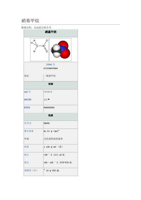
324硝基甲烷(化学式:CH3NO2)是最简单的有机硝基化合物。
室温下为无色油状有微弱芳香气味的透明液体,有较大的极性,可燃,有毒,具爆炸性。
可作燃料。
它可以和乙醇、丙酮、乙醚混溶,是一种良好的溶剂和萃取剂。
同时由于硝基α-氢具有较强的活性,故硝基甲烷也是化工和有机合成中的常见原料,用于制取药物、杀虫剂、炸药、染料和纤维等。
[编辑]制备工业上采取硝酸气相(350-450°C)硝化丙烷的方法制取硝基甲烷及其他低级的硝基化合物,比如硝基乙烷、1-硝基丙烷和2-硝基丙烷等。
反应为放热反应,自由基机理,中间体是烷基亚硝酸酯均裂产生的CH3CH2CH2O·类型的自由基。
它们大多不稳定,容易发生C-C键的断裂,故反应得到一硝基化合物以及低级硝基化合物的混合物。
[1]此外,甲烷/乙烷气相硝化法、氯乙酸钠与亚硝酸钠水溶液反应(方程式见下)、硫酸二甲酯与亚硝酸钠反应等方法都可以制得硝基甲烷。
由于这些反应物都是易得的化工原料,故硝基甲烷很容易制取,用途也很广泛。
ClCH2COONa + NaNO2 + H2O →CH3NO2 + NaCl + NaHCO3粗硝基甲烷冷却至凝固点以下,得到的固体用冷乙醚洗涤,再经蒸馏,便得到纯品。
[2][编辑]用途硝基甲烷在有机合成中为一碳合成子。
受硝基吸电子效应的影响,碳上的氢具有酸性,可以与碱作用去质子化。
生成的碳负离子可以与醛发生1,2-加成,生成β-羟基硝基化合物,若失水则生成硝基烯烃。
这个反应称为Henry反应。
作为亲核碳负离子的给体,硝基甲烷也可以和α,β-不饱和羰基化合物在碱催化下发生共轭加成,称为Michael加成反应。
硝基甲烷的衍生物包括三氯硝基甲烷(氯化苦)、三溴硝基甲烷、四硝基甲烷、三硝基甲烷等。
常用的缓冲液Tris,即“三羟甲基氨基甲烷”,就是由三羟甲基硝基甲烷经还原得到的。
[编辑]参考资料1. ^ Sheldon B. Markofsky “Nitro Compounds, Aliphatic”Ullmann's Encyclopediaof Industrial Chemistry 2002 by Wiley-VCH, Wienheim, 2002. DOI:10.1002/14356007.a17_401.2. ^ Coetzee, J. F. and Chang, T. H.. Recommended Methods for the Purification ofSolvents and Tests for Impurities: Nitromethane. Pure Appl. Chem.. 1986, 58:1541–1545.doi:10.1351/pac198658111541.查看条目评分给本文评分这是什么?可信度客观性完整性可读性我非常了解与本主题相关的知识(可选)提交评分8个分类:∙硝基甲烷∙硝基溶剂∙燃料∙火箭燃料∙液体炸药∙爆炸物∙燃料添加剂∙IARC第2B类致癌物质。
Eaton Moeller series Rapid Link速控器198844产品说明说明书
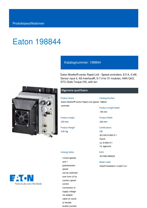
Eaton 198844Eaton Moeller® series Rapid Link - Speed controllers, 8.5 A, 4 kW, Sensor input 4, AS-Interface®, S-7.4 for 31 modules, HAN Q4/2, STO (Safe Torque Off), with fanAllgemeine spezifikationEaton Moeller® series Rapid Link Speed controller198844195 mm270 mm 220 mm 3.61 kgCEIEC/EN 61800-5-1 RoHS UL 61800-5-1 UL approval4015081969029RASP5-8400A31-4120011S1Product NameCatalog NumberProduct Length/Depth Product Height Product Width Product Weight Certifications Catalog Notes EANModel Code3 fixed speeds and 1 potentiometer speedcan be switched over from U/f to (vector) speed control Connection of supply voltage via adapter cable on round or flexible busbar junctionParameterization: drivesConnectParameterization: FieldbusParameterization: drivesConnect mobile (App)Internal and on heat sink, temperature-controlled Fan Diagnostics and reset on device and via AS-Interface Parameterization: KeypadPC connectionControl unitPTC thermistor monitoringKey switch position HANDKey switch position AUTOTwo sensor inputs through M12 sockets (max. 150 mA) for quick stop and interlocked manual operationIGBT inverterInternal DC linkThermo-click with safe isolationFanKey switch position OFF/RESETSelector switch (Positions: REV - OFF - FWD)STO (Safe Torque Off)3 fixed speeds1 potentiometer speed IP65NEMA 121st and 2nd environments (according to EN 61800-3)IIISpeed controllerAS-Interface profile cable: S-7.4 for 31 modulesASIC1: for conducted emissions onlyC2, C3: depending on the motor cable length, the connected load, and ambient conditions. External radio interference suppression filters (optional) may be necessary.2000 VCenter-point earthed star network (TN-S network)AC voltagePhase-earthed AC supply systems are not permitted.Vertical15 g, Mechanical, According to IEC/EN 60068-2-27, 11 ms, Half-sinusoidal shock 11 ms, 1000 shocks per shaftResistance: 57 Hz, Amplitude transition frequency on accelerationResistance: 10 - 150 Hz, Oscillation frequencyResistance: According to IEC/EN 60068-2-6Resistance: 6 Hz, Amplitude 0.15 mm Above 1000 m with 1 % performance reduction per 100 m Max. 2000 m-10 °C40 °C-40 °C70 °CFeatures Fitted with: Functions Degree of protectionElectromagnetic compatibility Overvoltage categoryProduct categoryProtocolRadio interference classRated impulse withstand voltage (Uimp) System configuration typeMounting position Shock resistance Vibration AltitudeAmbient operating temperature - min Ambient operating temperature - max Ambient storage temperature - min Ambient storage temperature - max< 95 %, no condensation In accordance with IEC/EN 50178Adjustable, motor, main circuit 0.8 - 8.5 A, motor, main circuit < 10 ms, On-delay < 10 ms, Off-delay 98 % (η)7.8 A3.5 mA120 %Maximum of one time every 60 seconds 380 V480 V380 - 480 V (-10 %/+10 %, at 50/60 Hz)Synchronous reluctance motors PM and LSPM motors U/f controlSensorless vector control (SLV) BLDC motors 0 Hz500 HzFor 60 s every 600 s At 40 °C12.7 AClimatic proofingCurrent limitationDelay timeEfficiency Input current ILN at 150% overload Leakage current at ground IPE - max Mains current distortion Mains switch-on frequencyMains voltage - min Mains voltage - max Mains voltage toleranceOperating modeOutput frequency - min Output frequency - max Overload current Overload current IL at 150% overload45 Hz66 Hz4 kW400 V AC, 3-phase480 V AC, 3-phase0.1 Hz (Frequency resolution, setpoint value)200 %, IH, max. starting current (High Overload), For 2 seconds every 20 seconds, Power section50/60 Hz8 kHz, 4 - 32 kHz adjustable, fPWM, Power section, Main circuitCenter-point earthed star network (TN-S network)AC voltagePhase-earthed AC supply systems are not permitted.5 HP≤ 0.6 A (max. 6 A for 120 ms), Actuator for external motor brakeAdjustable to 100 % (I/Ie), DC - Main circuit10 kAType 1 coordination via the power bus' feeder unit, Main circuit 24 V DC (-15 %/+20 %, external via AS-Interface® plug)AS-InterfacePlug type: HAN Q4/2Specification: S-7.4 (AS-Interface®)Max. total power consumption from AS-Interface® power supply unit (30 V): 190 mANumber of slave addresses: 31 (AS-Interface®)C3 ≤ 25 m, maximum motor cable length C2 ≤ 5 m, maximum motor cable length C1 ≤ 1 m, maximum motor cable lengthMeets the product standard's requirements.Meets the product standard's requirements.Rated frequency - minRated frequency - maxRated operational power at 380/400 V, 50 Hz, 3-phase Rated operational voltageResolutionStarting current - maxSupply frequencySwitching frequencySystem configuration type Assigned motor power at 460/480 V, 60 Hz, 3-phase Braking currentBraking torqueRated conditional short-circuit current (Iq)Short-circuit protection (external output circuits) Rated control voltage (Uc)Communication interfaceConnectionInterfacesCable length10.2.2 Corrosion resistance10.2.3.1 Verification of thermal stability of enclosures10.2.3.2 Verification of resistance of insulating materials tonormal heatMeets the product standard's requirements.Meets the product standard's requirements.Meets the product standard's requirements.Does not apply, since the entire switchgear needs to be evaluated.Does not apply, since the entire switchgear needs to be evaluated.Meets the product standard's requirements.Does not apply, since the entire switchgear needs to be evaluated.Meets the product standard's requirements.Does not apply, since the entire switchgear needs to be evaluated.Does not apply, since the entire switchgear needs to be evaluated.Is the panel builder's responsibility.Is the panel builder's responsibility.Is the panel builder's responsibility.Is the panel builder's responsibility.Is the panel builder's responsibility.The panel builder is responsible for the temperature rise calculation. Eaton will provide heat dissipation data for the devices.Firmware Update RASP 4.0Generation change from RA-MO to RAMO 4.0 Generationentausch RA-MO zu RAMO4.0Generation change from RA-SP to RASP 4.0 Elektromagnetische Verträglichkeit (EMV)Generationswechsel RASP4 zu RASP5Generation Change RASP4 to RASP5Generationenwechsel RA-SP zu RASP5Generation Change RA-SP to RASP5Generationentausch RAMO4 zu RAMO5Configuration to Rockwell PLC for Rapid LinkConfiguration to Rockwell PLC Rapid Link 5Generation change RAMO4 to RAMO5Generationentausch RA-SP zu RASP4.0Anschluss von Frequenzumrichtern an GeneratornetzeMN034004_DEMN040003_DERapid Link 5 - brochureDA-SW-drivesConnect - installation helpDA-SW-Driver DX-CBL-PC-3M0DA-SW-drivesConnectDA-SW-drivesConnect - InstallationshilfeDA-SW-USB Driver DX-COM-STICK3-KITDA-SW-USB Driver PC Cable DX-CBL-PC-1M5Material handling applications - airports, warehouses and intra-logistics ETN.RASP5-8400A31-4120011S1.edzIL034085ZUDE | Rapid Link 5Sortimentskatalog Antriebstechnik-DE10.2.3.3 Resist. of insul. mat. to abnormal heat/fire by internalelect. effects10.2.4 Resistance to ultra-violet (UV) radiation10.2.5 Lifting10.2.6 Mechanical impact10.2.7 Inscriptions10.3 Degree of protection of assemblies10.4 Clearances and creepage distances10.5 Protection against electric shock10.6 Incorporation of switching devices and components 10.7 Internal electrical circuits and connections10.8 Connections for external conductors10.9.2 Power-frequency electric strength10.9.3 Impulse withstand voltage10.9.4 Testing of enclosures made of insulating material 10.10 Temperature rise Anmerkungen zur AnwendungBenutzerhandbücherBroschüreneCAD model Installationsanleitung InstallationsvideosKatalogeEaton Konzern plc Eaton-Haus30 Pembroke-Straße Dublin 4, Irland © 2023 Eaton. Alle Rechte vorbehalten. Eaton ist eine eingetrageneMarke.Alle anderen Warenzeichen sindEigentum ihrer jeweiligenBesitzer./socialmediaIs the panel builder's responsibility. The specifications for the switchgear must be observed.Is the panel builder's responsibility. The specifications for the switchgear must be observed.The device meets the requirements, provided the information in the instruction leaflet (IL) is observed.ramo5_v28.dwgrasp5_v28.stpeaton-bus-adapter-rapidlink-speed-controller-dimensions-002.eps eaton-bus-adapter-rapidlink-speed-controller-dimensions-003.eps eaton-bus-adapter-rapidlink-speed-controller-dimensions.eps eaton-bus-adapter-rapidlink-speed-controller-dimensions-004.eps10.11 Short-circuit rating10.12 Electromagnetic compatibility 10.13 Mechanical function mCAD model Zeichnungen。
- 1、下载文档前请自行甄别文档内容的完整性,平台不提供额外的编辑、内容补充、找答案等附加服务。
- 2、"仅部分预览"的文档,不可在线预览部分如存在完整性等问题,可反馈申请退款(可完整预览的文档不适用该条件!)。
- 3、如文档侵犯您的权益,请联系客服反馈,我们会尽快为您处理(人工客服工作时间:9:00-18:30)。
8 Bit Microcontroller TLCS-870/X Series TMP88CH41UGRevision HistoryDate Revision2007/7/241First ReleaseTable of ContentsTMP88CH41UG1.1 Features . . . . . . . . . . . . . . . . . . . . . . . . . . . . . . . . . . . . . . . . . . . . . . . . . . . . . . . . . 11.2 Pin Assignment . . . . . . . . . . . . . . . . . . . . . . . . . . . . . . . . . . . . . . . . . . . . . . . . . . . . 31.3 Block Diagram. . . . . . . . . . . . . . . . . . . . . . . . . . . . . . . . . . . . . . . . . . . . . . . . . . . . . 41.4 Pin Names and Functions. . . . . . . . . . . . . . . . . . . . . . . . . . . . . . . . . . . . . . . . . . . . 52. Functional Description2.1 Functions of the CPU Core . . . . . . . . . . . . . . . . . . . . . . . . . . . . . . . . . . . . . . . . . . . 72.1.1 Memory Address Map (7)2.1.2 Program Memory (ROM) (8)2.1.3 Data Memory (RAM) (8)2.1.4 System Clock Control Circuit (9)2.1.4.1 Clock Generator2.1.4.2 Timing Generator2.1.4.3 Standby Control Circuit2.1.4.4 Controlling Operation Modes2.1.5 Reset Circuit (21)2.1.5.1 External Reset Input2.1.5.2 Adress Trap Reset2.1.5.3 Watchdog Timer Reset2.1.5.4 System Clock Reset3. Interrupt Control Circuit3.1 Interrupt latches (IL38 to IL2) . . . . . . . . . . . . . . . . . . . . . . . . . . . . . . . . . . . . . . . . 243.2 Interrupt enable register (EIR). . . . . . . . . . . . . . . . . . . . . . . . . . . . . . . . . . . . . . . . 253.2.1 Interrupt master enable flag (IMF) (25)3.2.2 Individual interrupt enable flags (EF38 to EF3) (25)3.3 Interrupt Sequence . . . . . . . . . . . . . . . . . . . . . . . . . . . . . . . . . . . . . . . . . . . . . . . . 283.3.1 Interrupt acceptance processing is packaged as follows (28)3.3.2 Saving/restoring general-purpose registers (29)3.3.2.1 Using Automatic register bank switcing3.3.2.2 Using register bank switching3.3.2.3 Using PUSH and POP instructions3.3.2.4 Using data transfer instructions3.3.3 Interrupt return (31)3.4 Software Interrupt (INTSW). . . . . . . . . . . . . . . . . . . . . . . . . . . . . . . . . . . . . . . . . . 323.4.1 Address error detection (32)3.4.2 Debugging (32)3.5 External Interrupts. . . . . . . . . . . . . . . . . . . . . . . . . . . . . . . . . . . . . . . . . . . . . . . . . 334. Special Function Register4.1 SFR. . . . . . . . . . . . . . . . . . . . . . . . . . . . . . . . . . . . . . . . . . . . . . . . . . . . . . . . . . . . 354.2 DBR. . . . . . . . . . . . . . . . . . . . . . . . . . . . . . . . . . . . . . . . . . . . . . . . . . . . . . . . . . . . 37i5. Input/Output Ports5.1 Port P1 (P15 to P10). . . . . . . . . . . . . . . . . . . . . . . . . . . . . . . . . . . . . . . . . . . . . . . 405.2 Port P2 (P22 to P20). . . . . . . . . . . . . . . . . . . . . . . . . . . . . . . . . . . . . . . . . . . . . . . 415.3 Port P3 (P37 to P30). . . . . . . . . . . . . . . . . . . . . . . . . . . . . . . . . . . . . . . . . . . . . . . 425.4 Port P4 (P47 to P40). . . . . . . . . . . . . . . . . . . . . . . . . . . . . . . . . . . . . . . . . . . . . . . 435.5 Port P6 (P67 to P60) . . . . . . . . . . . . . . . . . . . . . . . . . . . . . . . . . . . . . . . . . . . . . . 446. Time Base Timer (TBT) and Divider Output (DVO)6.1 Time Base Timer . . . . . . . . . . . . . . . . . . . . . . . . . . . . . . . . . . . . . . . . . . . . . . . . . 476.2 Divider Output (DVO) . . . . . . . . . . . . . . . . . . . . . . . . . . . . . . . . . . . . . . . . . . . . . . 497. Watchdog Timer (WDT)7.1 Watchdog Timer Configuration . . . . . . . . . . . . . . . . . . . . . . . . . . . . . . . . . . . . . . . 517.2 Watchdog Timer Control . . . . . . . . . . . . . . . . . . . . . . . . . . . . . . . . . . . . . . . . . . . . 527.2.1 Malfunction Detection Methods Using the Watchdog Timer (52)7.2.2 Watchdog Timer Enable (53)7.2.3 Watchdog Timer Disable (54)7.2.4 Watchdog Timer Interrupt (INTWDT) (54)7.2.5 Watchdog Timer Reset (55)8. 16-Bit TimerCounter 1 (TC1)8.1 Configuration . . . . . . . . . . . . . . . . . . . . . . . . . . . . . . . . . . . . . . . . . . . . . . . . . . . . 578.2 TimerCounter Control . . . . . . . . . . . . . . . . . . . . . . . . . . . . . . . . . . . . . . . . . . . . . . 588.3 Function. . . . . . . . . . . . . . . . . . . . . . . . . . . . . . . . . . . . . . . . . . . . . . . . . . . . . . . . . 608.3.1 Timer mode (60)8.3.2 External Trigger Timer Mode (62)8.3.3 Event Counter Mode (64)8.3.4 Window Mode (65)8.3.5 Pulse Width Measurement Mode (66)8.3.6 Programmable Pulse Generate (PPG) Output Mode (69)9. 16-Bit Timer (CTC)9.1 Configuration. . . . . . . . . . . . . . . . . . . . . . . . . . . . . . . . . . . . . . . . . . . . . . . . . . . . . 739.2 Control. . . . . . . . . . . . . . . . . . . . . . . . . . . . . . . . . . . . . . . . . . . . . . . . . . . . . . . . . . 749.3 Function. . . . . . . . . . . . . . . . . . . . . . . . . . . . . . . . . . . . . . . . . . . . . . . . . . . . . . . . . 779.3.1 Timer mode with software start (77)9.3.2 Timer mode with external trigger start (78)9.3.3 Event counter mode (79)9.3.4 Programmable Pulse Generate (PPG) output mode (80)10. 8-Bit TimerCounter 3 (TC3)10.1 Configuration. . . . . . . . . . . . . . . . . . . . . . . . . . . . . . . . . . . . . . . . . . . . . . . . . . . . 85ii10.2 TimerCounter Control . . . . . . . . . . . . . . . . . . . . . . . . . . . . . . . . . . . . . . . . . . . . . 8610.3 Function. . . . . . . . . . . . . . . . . . . . . . . . . . . . . . . . . . . . . . . . . . . . . . . . . . . . . . . . 8710.3.1 Timer mode (87)Figure 10-3 (89)10.3.3 Capture Mode (90)11. 8-Bit TimerCounter 4 (TC4)11.1 Configuration. . . . . . . . . . . . . . . . . . . . . . . . . . . . . . . . . . . . . . . . . . . . . . . . . . . . 9111.2 TimerCounter Control . . . . . . . . . . . . . . . . . . . . . . . . . . . . . . . . . . . . . . . . . . . . . 9211.3 Function. . . . . . . . . . . . . . . . . . . . . . . . . . . . . . . . . . . . . . . . . . . . . . . . . . . . . . . . 9311.3.1 Timer Mode (93)11.3.2 Event Counter Mode (93)11.3.3 Programmable Divider Output (PDO) Mode (93)11.3.4 Pulse Width Modulation (PWM) Output Mode (94)12. Motor Control Circuit (PMD: Programmable motor driver)12.1 Outline of Motor Control . . . . . . . . . . . . . . . . . . . . . . . . . . . . . . . . . . . . . . . . . . . 9812.2 Configuration of the Motor Control Circuit. . . . . . . . . . . . . . . . . . . . . . . . . . . . . 10012.3 Position Detection Unit . . . . . . . . . . . . . . . . . . . . . . . . . . . . . . . . . . . . . . . . . . . 10112.3.1 Configuration of the position detection unit (102)12.3.2 Position Detection Circuit Register Functions (103)12.3.3 Outline Processing in the Position Detection Unit (106)12.4 Timer Unit . . . . . . . . . . . . . . . . . . . . . . . . . . . . . . . . . . . . . . . . . . . . . . . . . . . . . 10712.4.1 Configuration of the Timer Unit (108)12.4.1.1 Timer Circuit Register Functions12.4.1.2 Outline Processing in the Timer Unit12.5 Three-phase PWM Output Unit. . . . . . . . . . . . . . . . . . . . . . . . . . . . . . . . . . . . . 11212.5.1 Configuration of the three-phase PWM output unit (112)12.5.1.1 Pulse width modulation circuit (PWM waveform generating unit)12.5.1.2 Commutation control circuit12.5.2 Register Functions of the Waveform Synthesis Circuit (116)12.5.3 Port output as set with UOC/VOC/WOC bits and UPWM/VPWM/WPWM bits (118)12.5.4 Protective Circuit (120)12.5.5 Functions of Protective Circuit Registers (122)12.6 Electrical Angle Timer and Waveform Arithmetic Circuit. . . . . . . . . . . . . . . . . . 12412.6.1 Electrical Angle Timer and Waveform Arithmetic Circuit (125)12.6.1.1 Functions of the Electrical Angle Timer and Waveform Arithmetic Circuit Registers12.6.1.2 List of PMD Related Control Registers13. Asynchronous Serial interface (UART)13.1 Configuration. . . . . . . . . . . . . . . . . . . . . . . . . . . . . . . . . . . . . . . . . . . . . . . . . . . 13713.2 Control . . . . . . . . . . . . . . . . . . . . . . . . . . . . . . . . . . . . . . . . . . . . . . . . . . . . . . 13813.3 Transfer Data Format . . . . . . . . . . . . . . . . . . . . . . . . . . . . . . . . . . . . . . . . . . . . 14013.4 Transfer Rate. . . . . . . . . . . . . . . . . . . . . . . . . . . . . . . . . . . . . . . . . . . . . . . . . . . 14113.5 Data Sampling Method . . . . . . . . . . . . . . . . . . . . . . . . . . . . . . . . . . . . . . . . . . . 14113.6 STOP Bit Length . . . . . . . . . . . . . . . . . . . . . . . . . . . . . . . . . . . . . . . . . . . . . . . . 14213.7 Parity. . . . . . . . . . . . . . . . . . . . . . . . . . . . . . . . . . . . . . . . . . . . . . . . . . . . . . . . . 14213.8 Transmit/Receive Operation . . . . . . . . . . . . . . . . . . . . . . . . . . . . . . . . . . . . . . . 14213.8.1 Data Transmit Operation (142)13.8.2 Data Receive Operation (142)13.9 Status Flag . . . . . . . . . . . . . . . . . . . . . . . . . . . . . . . . . . . . . . . . . . . . . . . . . . . . 143iii13.9.1 Parity Error (143)13.9.2 Framing Error (143)13.9.3 Overrun Error (143)13.9.4 Receive Data Buffer Full (144)13.9.5 Transmit Data Buffer Empty (144)13.9.6 Transmit End Flag (145)14. Synchronous Serial Interface (SIO)14.1 Configuration. . . . . . . . . . . . . . . . . . . . . . . . . . . . . . . . . . . . . . . . . . . . . . . . . . . 14714.2 Control. . . . . . . . . . . . . . . . . . . . . . . . . . . . . . . . . . . . . . . . . . . . . . . . . . . . . . . . 14814.3 Serial clock . . . . . . . . . . . . . . . . . . . . . . . . . . . . . . . . . . . . . . . . . . . . . . . . . . . . 14914.3.1 Clock source (149)14.3.1.1 Internal clock14.3.1.2 External clock14.3.2 Shift edge (151)14.3.2.1 Leading edge14.3.2.2 Trailing edge14.4 Number of bits to transfer . . . . . . . . . . . . . . . . . . . . . . . . . . . . . . . . . . . . . . . . . 15114.5 Number of words to transfer . . . . . . . . . . . . . . . . . . . . . . . . . . . . . . . . . . . . . . . 15114.6 Transfer Mode. . . . . . . . . . . . . . . . . . . . . . . . . . . . . . . . . . . . . . . . . . . . . . . . . . 15214.6.1 4-bit and 8-bit transfer modes (152)14.6.2 4-bit and 8-bit receive modes (154)14.6.3 8-bit transfer / receive mode (155)15. 10-bit AD Converter (ADC)15.1 Configuration. . . . . . . . . . . . . . . . . . . . . . . . . . . . . . . . . . . . . . . . . . . . . . . . . . . 15715.2 Register configuration . . . . . . . . . . . . . . . . . . . . . . . . . . . . . . . . . . . . . . . . . . . . 15815.3 Function. . . . . . . . . . . . . . . . . . . . . . . . . . . . . . . . . . . . . . . . . . . . . . . . . . . . . . 16115.3.1 Software Start Mode (161)15.3.2 Repeat Mode (161)15.3.3 Register Setting (162)15.4 STOP mode during AD Conversion. . . . . . . . . . . . . . . . . . . . . . . . . . . . . . . . . . 16315.5 Analog Input Voltage and AD Conversion Result . . . . . . . . . . . . . . . . . . . . . . . 16415.6 Precautions about AD Converter. . . . . . . . . . . . . . . . . . . . . . . . . . . . . . . . . . . . 16515.6.1 Analog input pin voltage range (165)15.6.2 Analog input shared pins (165)15.6.3 Noise Countermeasure (165)16. Input/Output Circuitry16.1 Control pins. . . . . . . . . . . . . . . . . . . . . . . . . . . . . . . . . . . . . . . . . . . . . . . . . . . . 16716.2 Input/output ports. . . . . . . . . . . . . . . . . . . . . . . . . . . . . . . . . . . . . . . . . . . . . . . . 16816.3 NC pins . . . . . . . . . . . . . . . . . . . . . . . . . . . . . . . . . . . . . . . . . . . . . . . . . . . . . . . 16817. Electrical Characteristics17.1 Absolute Maximum Ratings . . . . . . . . . . . . . . . . . . . . . . . . . . . . . . . . . . . . . . . 16917.2 Operating Conditions. . . . . . . . . . . . . . . . . . . . . . . . . . . . . . . . . . . . . . . . . . . . . 17017.3 DC Characteristics. . . . . . . . . . . . . . . . . . . . . . . . . . . . . . . . . . . . . . . . . . . . . . . 17017.4 AD Conversion Characteristics . . . . . . . . . . . . . . . . . . . . . . . . . . . . . . . . . . . . . 171iv17.5 AC Characteristics. . . . . . . . . . . . . . . . . . . . . . . . . . . . . . . . . . . . . . . . . . . . . . . 17117.5 . . . . . . . . . . . . . . . . . . . . . . . . . . . . . . . . . . . . . . . . . . . . . . . . . . . . . . . . . . . . . . 17117.5 (171)17.5 (171)17.6 Recommended Oscillation Conditions. . . . . . . . . . . . . . . . . . . . . . . . . . . . . . . . 17217.7 Handling Precaution . . . . . . . . . . . . . . . . . . . . . . . . . . . . . . . . . . . . . . . . . . . . . 17218. Package DimensionsThis is a technical document that describes the operating functions and electrical specifications of the 8-bit microcontroller series TLCS-870/X (LSI).vviTMP88CH41UG元器件交易网1.3 Block DiagramTMP88CH41UGBlock Diagram1.3 Array Figure 1-2 Block DiagramTMP88CH41UG1.4Pin Names and FunctionsTable 1-1 Pin Names and Functions(1/2)Pin Name Pin Number Input/Output FunctionsP1542IO PORT15P14PPG141IOOPORT14PPG1 outputP13DVO40IOOPORT13Divider OutputP12INT2TC139IOIIPORT12External interrupt 2 inputTC1 inputP11INT138IOIPORT11External interrupt 1 inputP10INT037IOIPORT10External interrupt 0 inputP22TC4INT4PWM4/PDO47IOIIOPORT22TC4 inputExternal interrupt 4 inputPWM4/PDO4 outputP21TC3INT36IOIIPORT21TC3 pin inputExternal interrupt 3 inputP20INT5STOP9IOIIPORT20External interrupt 5 inputSTOP mode release signal inputP37CL117IOIPORT37PMD over load protection input1P36EMG116IOIPORT36PMD emergency stop input1P35U115IOOPORT35PMD control output U1P34V114IOOPORT34PMD control output V1P33W113IOOPORT33PMD control output W1P32X112IOOPORT32PMD control output X1P31Y111IOOPORT31PMD control output Y1P30Z110IOOPORT30PMD control output Z1P47CTC25IOIPORT47CTC inputP46PPG224IOIPORT46PPG2 outputP45SOTXD23IOOOPORT45Serial Data OutputUART data output元器件交易网1.4 Pin Names and FunctionsTMP88CH41UGP44SI RXD 22IO I I PORT44Serial Data Input UART data input P43SCK21IO IO PORT43Serial Clock I/O P42PDU120IO I PORT42PMD control input U1P41PDV119IO I PORT41PMD control input V1P40PDW118IO I PORT40PMD control input W1P67AIN7DBOUT133IO I O PORT67Analog Input7PMD debug output1P66AIN632IO I PORT66Analog Input6P65AIN531IO I PORT65Analog Input5P64AIN430IO I PORT64Analog Input4P63AIN329IO I PORT63Analog Input3P62AIN228IO O PORT62Analog Input2P61AIN127IO I PORT61Analog Input1P60AIN026IO I PORT60Analog Input0XIN 2I Resonator connecting pins for high-frequency clock XOUT3O Resonator connecting pins for high-frequency clock RESET20IOReset signalTEST 4ITest pin for out-going test and the Serial PROM mode control pin. Usually fix to low level. Fix to high level when the Serial PROM mode starts.VAREF 34I Analog Base Voltage Input Pin for A/D Conversion AVDD 35I Analog Power Supply AVSS 36I Analog Power Supply VDD 24IO +5V VSS 25IO 0(GND)NC 43I Non Connection NC44INon ConnectionTable 1-1 Pin Names and Functions(2/2)Pin NamePin Number Input/OutputFunctions元器件交易网TMP88CH41UG元器件交易网2. Functional Description 2.1 Functions of the CPU CoreTMP88CH41UG2.1.2Program Memory (ROM)The TMP88CH41UG contains 16Kbytes program memory (MaskROM) located at addresses 04000H to07EFFH and addresses FFF00H to FFFFFH.2.1.3Data Memory (RAM)The TMP88CH41UG contains 512bytes +128bytes RAM. The first 128bytes location (00040H to 000BFH)of the internal RAM is shared with a general-purpose register bank.The content of the data memory is indeterminate at power-on, so be sure to initialize it in the initialize rou-tine.Note:Because general-purpose registers exist in the RAM, never clear the current bank address of RAM. In theabove example, the RAM is cleared except bank 0.Example :Clearing the internal RAM of the TMP88CH41UG (clear all RAM addresses to 0, except bank 0)LD HL, 0048H ; Set the start addressLD A, 00H ; Set the initialization data (00H)LDBC, 277H ; Set byte counts (-1)SRAMCLR:LD (HL+), A DEC BCJRSF, SRAMCLR元器件交易网TMP88CH41UG元器件交易网元器件交易网2. Functional Description2.1 Functions of the CPU CoreTMP88CH41UGTMP88CH41UG元器件交易网元器件交易网2. Functional Description2.1 Functions of the CPU CoreTMP88CH41UGTMP88CH41UGNote 1:When entering from NORMAL mode into STOP mode, always be sure to set SYSCR1<RETM> to 0.Note 2:When the device is released from STOP mode by RESET pin input, it always returns to NORMAL mode regardless of howSYSCR1<RETM> is set.Note 3:fc: High-frequency clock [Hz], *: Don’t careNote 4:The values of the SYSCR1 Register bits 1 and 0 are indeterminate when read.Note 5:When placed the device in STOP mode, make sure to set "1" to SYSCR1<OUTEN>.Note 6:Releasing the device from the STOP mode causes the STOP bit to be automatically cleared to “0”.Note 7:Select an appropriate value for the warm-up time according to the characteristic of the resonator used.Note 1:When exiting STOP mode, SYSCR2<XEN and SYSCK> are automatically rewritten according to SYSCR1<RETM>..Note 2:When SYSCR2<XEN>is cleared to 0, the device is reset.Note 3:WDT: Watchdog Timer, *: Don’t careNote 4:Be sure to write "0" to SYSCR2 Register bit6.Note 5:The values of the SYSCR2 Register bits 3 to 0 are indeterminate when read.Note 6:Change the operation mode after disabling external interrupts. If interrupts are enabled after changing operation mode,clear interrupt latches as appropriate in advance.System Control Register 1SYSCR1(0038H)7654321STOPRELMRETMOUTENWUT(Initial value: 0000 00**)STOPPlace the device in STOP mode0: Keep the CPU core and peripheral hardware operating1: Stop the CPU core and peripheral hardware (placed in STOP mode)R/WRELMSelect method by which the device is released from STOP mode0: Released by a rising edge on STOP pin input 1: Released by a high level on STOP pin input RETM Select operation mode after exiting STOP mode0: Returns to NORMAL mode 1: ReservedOUTENSelect port output state during STOP mode0: High-impedance state 1: Hold outputWUTUnit of warm-up time when exiting STOP modeWhen Returning to NORMAL Mode DV1CK = 0DV1CK = 100 3 × 216/fc 3 × 217/fc 01216/fc 217/fc 10214/fc 215/fc 11ReservedReservedSystem Control Register 2SYSCR2(0039H)7654321XENSYSCKIDLE(Initial value: 1000 ****)XEN Control high-frequency oscilla-tor0: Stop oscillation1: Continue or start oscillatingR/W SYSCK Select (write)/monitor (read) system clock0: High-frequency clock (NORMAL/IDLE)1: ReservedR/W IDLEPlace the device in IDLE mode0: Keep the CPU and WDT operating1: Stop the CPU and WDT (IDLE mode entered)R/WRETM Operation Mode after Releasing STOP Mode XEN SYSCK 0NORMAL mode 101No operation1元器件交易网2. Functional Description2.1 Functions of the CPU CoreTMP88CH41UG2.1.4.4Controlling Operation Modes(1)STOP modeSTOP mode is controlled by System Control Register 1 (SYSCR1) and the STOP pin input. TheSTOP pin is shared with P20 port and INT5 (external interrupt input 5). STOP mode is entered into bysetting STOP (SYSCR1 Register bit 7) to 1. During STOP mode, the device retains the followingstate.1.Stop oscillation, thereby stopping operation of all internal circuits.2.The data memory, register, program status word, and port output latch hold the state inwhich they were immediately before entering STOP mode.3.Clear the prescaler and divider for the timing generator to 0.4.The program counter holds the instruction address two instructions ahead the one thatplaced the device in STOP mode (e.g., “SET (SYSCR1).7”).The device is released from STOP mode by the active level or edge on STOP pin input as selectedby SYSCR1<RELM>.Note:Before entering STOP mode, be sure to disable interrupts. This is because if the signal on anexternal interrupt pin changes state during STOP (from entering STOP mode till completion ofwarm-up) the interrupt latch is set to 1, so that the device may accept the interrupt immediatelyafter exiting STOP mode. Also, when reenabling interrupts after exiting STOP mode, be sure toclear the unnecessary interrupt latches beforehand.a.Released by level (when RELM = 1)The device is released from STOP mode by a high level on STOP pin input.Any instruction to place the device in STOP mode is ignored when executed while STOPpin input level is high, and the device immediately goes to a release sequence (warm-up)without entering STOP mode. Therefore, before STOP mode can be entered while RELM =1, the STOP pin input must be verified to be low in a program. There are following methodsto do this verification.1.Testing the port status2.INT5 interrupt (interrupt generated at a falling edge on INT5 pin input)Example 1 :Entering STOP mode from NORMAL mode by testing P20 portLD(SYSCR1), 01010000B; Select to be released from STOP mode by levelSSTOPH :TEST(P2DR) . 0; Wait until STOP pin input goes lowJRS F, SSTOPHDI; IMF ← 0SET(SYSCR1) . 7; Place the device in STOP modeExample 2 :Entering STOP mode from NORMAL mode by INT5 interruptPINT5 :TEST(P2DR) . 0; Do not enter STOP mode if P20 port input level is high, to eliminate noiseJRS F, SINT5; Do not enter STOP mode if P20 port input level is high, to eliminate noiseLD(SYSCR1), 01010000B; Select to be released from STOP mode by levelDI; IMF ← 0SET(SYSCR1) . 7; Place the device in STOP modeSINT5 :RETI元器件交易网TMP88CH41UG元器件交易网2. Functional Description 2.1 Functions of the CPU CoreTMP88CH41UGThe device is released from STOP mode following the sequence described below.1.Only the high-frequency oscillator is oscillating.2. A warm-up time is inserted in order to allow for the clock oscillation to stabilize. Duringwarm-up, the internal circuits remain idle. The warm-up time can be selected from three choices according to the oscillator characteristics by using SYSCR1<WUT>.3.After an elapse of the warm-up time, the device restarts normal operation beginning with the instruction next to one that placed it in STOP mode. At this time, the prescaler and divider for the timing generator start from the zero-cleared state.Note:Because the warm-up time is obtained from the fundamental clock by dividing it, if the oscillationfrequency fluctuates while exiting STOP mode, the warm-up time becomes to have some error. Therefore, the warm-up time must be handled as an approximate value.The device can also be released from STOP mode by pulling the RESET pin input low, in which case the device is immediately reset as is normally reset by RESET . After reset, the device starts oper-ating from NORMAL mode.Note:When exiting STOP mode while the device is retained at low voltage, the following caution isrequired.Before exiting STOP mode, the power supply voltage must be raised to the operating voltage. At this time, the RESET pin level also is high and rises along with the power supply voltage. If the device has a time-constant circuit added external to the chip, the voltage on RESET pin input does not rise as fast as the power supply voltage. Therefore, if the voltage level on RESET pin input is below the RESET pin’s noninverted, high-level input voltage (hysteresis input), the device may be reset.Table 2-2 Warm-up Time (Example: fc = 20 MHz)WUTWarm-up Time [ms]When Returning to NORMAL Mode DV1CK = 0DV1CK = 1009.83119.66201 3.277 6.554100.819 1.63811ReservedReserved元器件交易网TMP88CH41UG元器件交易网元器件交易网2. Functional Description2.1 Functions of the CPU CoreTMP88CH41UGTMP88CH41UGThe device can be released from IDLE mode normally or by an interrupt as selected with the inter-rupt master enable flag (IMF).a.Released normally (when IMF = 0)The device can be released from IDLE mode by the interrupt source enabled by the inter-rupt individual enable flag (EF), and restarts execution beginning with the instruction next to one that placed it in IDLE mode. The interrupt latch (IL) for the interrupt source used to exit IDLE mode normally needs to be cleared to 0 using a load instruction.b.Released by interrupt (when IMF = 1)The device can be released from IDLE mode by the interrupt source enabled by the inter-rupt individual enable flag (EF), and enters interrupt handling. After interrupt handling, the device returns to the instruction next to one that placed it in IDLE mode.The device can also be released from IDLE mode by pulling the RESET pin input low, in which case the device is immediately reset as is normally reset by RESET . After reset, the device starts oper-ating from NORMAL mode.Note:If a watchdog timer interrupt occurs immediately before entering IDLE mode, the device pro-cesses the watchdog timer interrupt without entering IDLE mode.元器件交易网元器件交易网2. Functional Description2.1 Functions of the CPU CoreTMP88CH41UGTMP88CH41UG元器件交易网2. Functional Description 2.1 Functions of the CPU CoreTMP88CH41UGNote:Read-modify-write instructions, such as a bit manipulation, cannot access ATAS or ATKEY register because these registerare write only.Note 1:In development tools, address trap cannot be prohibited in the internal RAM,SFR or DBR area withthe address trap control registers. When using development tools, even if the address trap permis-sion/prohibition setting is changed in the user’s program, this change is ineffective. To execute instructions from the RAM area, development tools must be set accordingly.Note 2:While the SWI instruction at an address immediately before the address trap area is executing, theprogram counter is incremented to point to the next address in the address trap area; an address trap is therefore taken immediately.Development tool setting •To prohibit the address trap:1.Modify the iram (mapping attribute) area to (00040H to 000BFH) in the memory map win-dow.2.Set 000C0H to "address trap prohibition area" as a new eram (mapping attribute) area.3.Load the user program4.Execute the address trap prohibition code in the user’s program2.1.5.3Watchdog Timer ResetRefer to the Section “Watchdog Timer.”2.1.5.4System Clock ResetWhen SYSCR2<XEN> is cleared to 0 or when SYSCR2<XEN> is cleared to 0 while SYSCR2<SYSCK> = 0, the system clock is turned off, causing the CPU to become locked up. To prevent this problem, upon detecting SYSCR2<XEN> = 0, SYSCR2<XEN> = SYSCR2<SYSCK> = 0 or SYSCR2<SYSCK> = 1, the device automatically generates an internal reset signal to let the system clock continue oscillating.Address Trap Control RegisterATAS(1F94H)76543210-------ATAS(initial value: **** ***0)ATASSelect the address trap permission / prohibition0: Permit address trap 1: Prohibit address trap(It may be available after setting control code for ATKEY register)Write onlyAddress Trap Control Code RegisterATKEY (1F95H)7654321(initial value: **** ****)ATKEYWrite control code to prohibit address trap D2H: Address trap prohibition code Others: Ineffective Write only元器件交易网。