Method of Cone Calorimeter Used for Estimation of the Visibility
dematal方法的英文表达
dematal方法的英文表达Dematal Method: A Comprehensive Overview.The Dematal method, often referred to as Deming's 14 Points or Deming's philosophy, is a set of principles and guidelines for improving the quality of products and services. Developed by the renowned management expert Edward Deming, this methodology has been widely adopted by organizations across various industries, aiming to enhance operational efficiency, reduce waste, and improve customer satisfaction.Deming's 14 Points outline a comprehensive approach to quality management, focusing on the systematic elimination of defects and errors rather than mere inspection or testing. These points emphasize the importance of leadership, employee training, process improvement, and customer focus, among other critical areas.The first point emphasizes the need for organizationsto adopt a long-term perspective in their pursuit of quality. This means that companies should focus on sustainable improvements rather than short-term fixes, ensuring that their quality efforts are sustainable and scalable.The second point highlights the importance of improving product quality by constantly seeking to understand and address the root causes of problems. Deming believed that focusing on symptoms alone was insufficient; instead, organizations needed to dig deep to understand the underlying issues that were causing defects and errors.The third point emphasizes the role of management in setting clear goals and expectations for quality. Management should communicate these goals to employees and provide them with the tools and resources necessary to achieve them.The fourth point emphasizes the importance of adopting a proactive approach to quality management, seeking to prevent problems before they occur rather than waiting tofix them after they have arisen. This requires a culture of continuous improvement and a focus on process control.The fifth point emphasizes the need for management to recognize and reward employees for their contributions to quality. This fosters a culture of engagement and ownership, where employees feel valued and motivated to contribute to quality efforts.The sixth point highlights the importance of employee training and education in achieving quality. Demingbelieved that employees were the backbone of anyorganization and that investing in their development was crucial to achieving long-term success.The seventh point emphasizes the need for management to remove barriers that prevent employees from contributing to quality efforts. This includes providing them with the freedom to suggest improvements, implement changes, andtake ownership of their work.The eighth point highlights the importance ofdeveloping strong relationships with suppliers and partners to ensure the quality of incoming materials and components. This requires a focus on supply chain management and the development of long-term relationships based on trust and mutual respect.The ninth point emphasizes the need for organizations to continuously improve their processes and procedures. This involves regularly reviewing and revising processes to eliminate waste, increase efficiency, and reduce the potential for errors.The tenth point highlights the importance of using statistical methods to understand and manage variation in processes. Deming believed that by understanding and controlling variation, organizations could achieve consistent and predictable results.The eleventh point emphasizes the need for organizations to implement rigorous quality control systems to ensure that products and services meet customer requirements. This requires a focus on prevention ratherthan inspection, with quality being built into products and services from the outset.The twelfth point highlights the importance of management's role in setting an example of quality leadership. Management should demonstrate a commitment to quality by their actions and decisions, creating a culture where quality is valued and expected.The thirteenth point emphasizes the need for organizations to focus on improving their products and services from the customer's perspective. This requires a deep understanding of customer needs and expectations, as well as a focus on delivering value and satisfaction.The fourteenth point serves as a reminder that improving quality is a never-ending journey. Organizations should always strive to improve their processes, products, and services, seeking to eliminate defects and errors wherever they may occur.In conclusion, the Dematal method provides acomprehensive framework for organizations seeking to improve the quality of their products and services. By adopting these principles and guidelines, companies can create a culture of continuous improvement, engage their employees, and deliver value to their customers. While implementing the Dematal method may require significant time and effort, the resulting improvements in quality, efficiency, and customer satisfaction are well worth the investment.。
四川大学化工考研884复试面试英语题库翻译原文

1.When a fluid flows through a duct or over a surface, the velocity over a place at right angles tothe stream is not normally uniform. The variation of velocity can be shown by the use ofstreamlines which are lines so drawn that the velocity vector is always tangential to them. The flow rate between any two streamlines is always the same. Constant velocity over a cross-section is shown by equidistant streamlines and increase in velocity by closer spacing ofstreamlines.2.It is found the heat transfer rate per unit area q is dependent on those physical propertieswhich affect flow pattern. The thermal properties of the fluid and the velocity of flow the fluid over the surface, the temperature difference t and a factor deternming the natural circulation effect cause by expansion of the fluid on heating.3.The oil distilled in a very large steel tower, the technical names of which is the fractionatingtower. The tower is thirty to fifty meters tall and its diameter is one to three meters. It isdivided into chambers, each of which contains a layer of trays. There are holes in the trays. The chanbers are at different heights, and temperature at each height is different.4. A group of operation for separating the components of mixture is based on the transfer ofmaterial from one homogeneous phase to anther. Unlike purely mechanical separation, these methods utilize differences in vapor pressure or solubility, not density or particle size. The driving force for transfer is a conoantration differce to or a concentration gradient, much as a temperature difference or a temperature gradient provides the driving force heat transfer.5.The three most important characteristics of an individual particle are its composition, its sizeand its shape. Composition determine such properties as density and conductivity, provided that the particle is completely uniform. A particle shape may be regular such as spherical or cubic, or it may be irregular as, for example, with a piece of broken glass.6.homogeneous catalysis is the industrical oxo process for manufacturing normal iosobuty(异丁醛)。
锥形量热仪的工作原理及应用

到火焰熄灭为止所释放热量的总和 ,即
t
THR = ∫HRR ,单位为 MJ / m2 。
t =0
end
将 HRR 与 THR 结合起来 , 可以更好地评价材料 的燃烧性和阻燃性 , 对火灾研究具有更为客观 、 全面 的指导作用 。 313 质量损失速率 ( Ma ss Lo ss Rate ,简称 MLR)
HRR 是指在预置的入射热流强度下 ,材料被点燃
后 ,单位面积的热量释放速率 ,即
・
q 1 ΔHC q″ = = × 1 . 10 ×c A A r0
・
ΔP
Te
x02 - xO2
0
1 . 105 - 1 . 502
( 6)
HRR 是表征火灾强度的最重要性能参数 ,单位为 kW/ m2 ; HRR 的 最 大 值 为 热 释 放 速 率 峰 值 ( Peak of HHR ,简称 pkHRR) ,pkHRR 的大小表征了材料燃烧时
王庆国 张军 张峰
( 青岛科技大学高分子科学与工程学院 青岛 266042)
E2mail :qgwang @263. sina. com
摘 要 锥形量热仪是当前能够表征材料燃烧性能的最为理想的试验仪器 ,它的试验环境同火灾材料的真实燃 烧环境接近 ,所得试验数据能够评价材料在火灾中的燃烧行为 。本文介绍了锥形量热仪的结构 、 工作原理和应用 ,并 就燃烧性能在材料评价 、 材料设计和火灾预防等方面的重要意义作了阐述 。 关键词 锥形量热仪 ; 氧耗原理 ; 燃烧性能 中图分类号 TH89
作者简介 : 王庆国 ,男 ,1971 年生 ,讲师 ,山东莒南人 ,现主要从事高聚物材料阻燃和火灾中高聚物材料燃烧行为研究 。
C1702
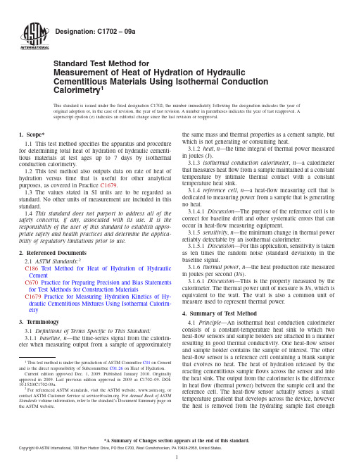
Designation:C1702–09aStandard Test Method forMeasurement of Heat of Hydration of Hydraulic Cementitious Materials Using Isothermal Conduction Calorimetry1This standard is issued under thefixed designation C1702;the number immediately following the designation indicates the year of original adoption or,in the case of revision,the year of last revision.A number in parentheses indicates the year of last reapproval.A superscript epsilon(´)indicates an editorial change since the last revision or reapproval.1.Scope*1.1This test method specifies the apparatus and procedure for determining total heat of hydration of hydraulic cementi-tious materials at test ages up to7days by isothermal conduction calorimetry.1.2This test method also outputs data on rate of heat of hydration versus time that is useful for other analytical purposes,as covered in Practice C1679.1.3The values stated in SI units are to be regarded as standard.No other units of measurement are included in this standard.1.4This standard does not purport to address all of the safety concerns,if any,associated with its use.It is the responsibility of the user of this standard to establish appro-priate safety and health practices and determine the applica-bility of regulatory limitations prior to use.2.Referenced Documents2.1ASTM Standards:2C186Test Method for Heat of Hydration of Hydraulic CementC670Practice for Preparing Precision and Bias Statements for Test Methods for Construction MaterialsC1679Practice for Measuring Hydration Kinetics of Hy-draulic Cementitious Mixtures Using Isothermal Calorim-etry3.Terminology3.1Definitions of Terms Specific to This Standard:3.1.1baseline,n—the time-series signal from the calorim-eter when measuring output from a sample of approximately the same mass and thermal properties as a cement sample,but which is not generating or consuming heat.3.1.2heat,n—the time integral of thermal power measured in joules(J).3.1.3isothermal conduction calorimeter,n—a calorimeter that measures heatflow from a sample maintained at a constant temperature by intimate thermal contact with a constant temperature heat sink.3.1.4reference cell,n—a heat-flow measuring cell that is dedicated to measuring power from a sample that is generating no heat.3.1.4.1Discussion—The purpose of the reference cell is to correct for baseline drift and other systematic errors that can occur in heat-flow measuring equipment.3.1.5sensitivity,n—the minimum change in thermal power reliably detectable by an isothermal calorimeter.3.1.5.1Discussion—For this application,sensitivity is taken as ten times the random noise(standard deviation)in the baseline signal.3.1.6thermal power,n—the heat production rate measured in joules per second(J/s).3.1.6.1Discussion—This is the property measured by the calorimeter.The thermal power unit of measure is J/s,which is equivalent to the watt.The watt is also a common unit of measure used to represent thermal power.4.Summary of Test Method4.1Principle—An isothermal heat conduction calorimeter consists of a constant-temperature heat sink to which two heat-flow sensors and sample holders are attached in a manner resulting in good thermal conductivity.One heat-flow sensor and sample holder contains the sample of interest.The other heat-flow sensor is a reference cell containing a blank sample that evolves no heat.The heat of hydration released by the reacting cementitious sampleflows across the sensor and into the heat sink.The output from the calorimeter is the difference in heatflow(thermal power)between the sample cell and the reference cell.The heat-flow sensor actually senses a small temperature gradient that develops across the device,however the heat is removed from the hydrating sample fast enough1This test method is under the jurisdiction of ASTM Committee C01on Cementand is the direct responsibility of Subcommittee C01.26on Heat of Hydration.Current edition approved Dec.1,2009.Published January2010.Originallyapproved st previous edition approved in2009as C1702–09.DOI:10.1520/C1702-09a.2For referenced ASTM standards,visit the ASTM website,,orcontact ASTM Customer Service at service@.For Annual Book of ASTMStandards volume information,refer to the standard’s Document Summary page onthe ASTM website.*A Summary of Changes section appears at the end of this standard. Copyright©ASTM International,100Barr Harbor Drive,PO Box C700,West Conshohocken,PA19428-2959,United States.that,for practical purposes,the sample remains at a constant temperature(isothermal).4.2The output from the heat-flow sensor is an electrical voltage signal that is proportional to the thermal power from the sample.This output must be calibrated to a known thermal power.In this method this is accomplished by measurements on a heat source that emits a constant and known power level. The integral of the thermal power over the time of the test is the heat of hydration.4.3Two methods are described.In Method A the sample and water are both temperature equilibrated and mixed inside the calorimeter.This method is the most direct way to determine heat of hydration.In Method B the sample is mixed outside of the calorimeter then put into the calorimeter.This method offers certain practicality,but depending on the materials being analyzed and procedures used for mixing and handling,this method may suffer from small errors due to periods of hydration being missed or spurious heat being introduced or taken away from the calorimeter during setup or combinations thereof.Methods of correction are offered for these potential errors.5.Significance and Use5.1This method is suitable for determining the total heat of hydration of hydraulic cement at constant temperature at ages up to7days to confirm specification compliance.It gives test results equivalent to Test Method C186up to7days of age (Poole(2007)(4)).5.2This method compliments Practice C1679by providing details of calorimeter equipment,calibration,and operation. Practice C1679emphasizes interpretation significant events in cement hydration by analysis of time dependent patterns of heatflow,but does not provide the level of detail necessary to give precision test results at specific test ages required for specification compliance.6.Apparatus6.1Miscellaneous Equipment:6.1.1Balance—Accurate to0.01g.6.1.2Volumetric Dispenser—A device for measuring vol-ume or mass of water,accurate to0.1mL.This could be a syringe,pipette,or weighing device.6.1.3Sample Holder—A device that holds the cement paste and provides intimate contact with the calorimeter heat sensing device and prevents evaporation of mixing water.If using commercially manufactured equipment,consult the recom-mendations of the manufacturer in choosing sample holders.6.1.4Resistance Heater—An electrical device fabricated from material with similar heat capacity and shape as the test sample,but containing a resistor connected to a constant-voltage power supply such that a stable output of0.0106 0.0002J/s can be generated(see Note1).N OTE1—A simple procedure for fabricating heaters and blanks having the same approximate shape and heat capacity as a sample is to make specimen similar to one used in a determination out of plaster of Paris embedded with a small resistor.Plaster of Paris has only a transient heat of hydration and is not aggressive to electronic components.A resistance of100-300ohms is a convenient value when using voltages of0.1-10 volts to drive heat production.6.1.5Reference Specimen—A sample fabricated from an inert material with similar heat capacity and shape as the test sample.This is used in the reference cell.6.1.6Multimeter—An instrument for measuring DC voltage and resistance values for the resistance heater described in 6.1.4to an accuracy of1%.This instrument is only required if the calorimeter does not contain built-in calibration capability.6.1.7Power Supply—A constant voltage DC power supply with a power output range sufficient to simulate the maximum output of a hydrating cement sample(see Note2).This equipment is only required if an instrument does not contain built-in calibration capability.N OTE2—A power output of at least0.33J/s is needed for most applications.6.1.8Insulated Container—Used in the Method B de-scribed in8.3.5.1.This device can be fabricated using a500 mL(approximate volume)container insulated with at least30 mm of polystyrene on the sides and top.6.1.9Temperature Measuring Device—Used in Method B described in8.3.5.1.The device shall be capable of measuring temperature changes to the nearest0.1°C and of a physical configuration that allows it to operate in the confines of the insulated container described in6.1.8.6.2Calorimeter—The schematic design of a calorimeter is given in Fig.1.It shall consist of a sample holder for the test and reference specimens,each thermally connected to heat flow sensors,which are thermally connected to a constant-temperature heat sink.The actual design of anindividual FIG.1Schematic Drawing of a Heat ConductionCalorimeterinstrument,whether commercial or homemade,may vary,but it should follow the criteria given below.Any other suitable arrangement that satisfies sections 6.2.1,6.2.2,and 6.2.3is acceptable.6.2.1Instrument Stability —The baseline shall exhibit a low random noise level and be stable against drift.This property shall be verified on a new instrument and whenever there are questions about performance.The rate of change of the baseline measured during a time period of 3days shall be #20µJ/s per gram sample per hour of the test and a baseline random noise level of #10µJ/s per gram sample (see Note 3).In practice the baseline is measured for 3days and a straight line is fitted to the power (J/g/s)versus time (h)data using a linear regression procedure.The long term drift is then the slope in the line J/g/s/h and the baseline noise level is the standard deviation (J/g/s)around this regression line.N OTE 3—The rationale for these limits is found in Poole (2007)(4).6.2.2Instrument Sensitivity —The minimum sensitivity for measuring power output shall be 100µJ/s.6.2.3Isothermal Conditions —The instrument shall main-tain the temperature of the sample to within 1K of the thermostated temperature.6.3Data Acquisition Equipment —Data acquisition equip-ment may be built into the calorimeter instrument package,or it may be an off-the-shelf,stand-alone,item.The data acqui-sition equipment shall be capable of performing continuous logging of the calorimeter output measurement at a minimum time interval of 10s.It is useful,for purposes of reducing amount of data,to have the flexibility to adjust the readinginterval to longer times when power output from the sample is low.Some data acquisition equipment is designed to automati-cally adjust reading intervals in response to power output.The equipment shall have at least 4.5-digit-measuring capability,with an accuracy of 1%,or comparable capabilities to condi-tion the power output into the same quality as integrated signal amplifiers.7.Instrument Calibration7.1Instrument Calibration —Commercially manufactured instruments designed for measuring heat of hydration of cementitious materials may have instrument specific calibra-tion procedures.Conform to these procedures if they exist.In addition,the instrument shall be capable of providing data described in 7.1.1.1,7.1.2.1,and 7.1.2.2,and calculations in 7.1.4.If there are no instrument calibration procedures,cali-brate the instrument according to the following procedure.Calibration shall be at least a two-point process.This is illustrated schematically in Fig.2.7.1.1Mount the resistance heater and the blank specimen in their respective measuring cells and start data collection.This step measures the baseline calorimeter output (in units of V or mV)when no heat is being generated.7.1.1.1Measure this baseline when it reaches a constant value (drift #20µJ/s per gram sample per hour).7.1.1.2Record this output as V 0for P 0=0(see Note 4).N OTE 4—V 0may not be zero voltage,but may be a positive or negative number.The practice of using a test cell and a reference cell usually results in the V 0being a relatively small number but,depending on the variability in properties of some hardware,it may not bezero.FIG.2(A)Schematic Steady-State Calibration Using A 2-Point Calibration Process And (B)Multi-Point CalibrationProcess7.1.2Power in the heater circuit is related to voltage and resistance by the following equation:P5I2R(1) where:P=power,J/s,I=applied current,amperes,andR=resistance,ohms.Apply sufficient voltage to the heater circuit to generate a heat output of approximately0.1J/s,measured to an accuracy of 5%.7.1.2.1Allow the output to stabilize signal at a drift of #0.1%over60min or#0.05%over30min.7.1.2.2Record this output as V1for a power P1(see Note5). This is the minimum requirement for a calibration sequence.At the users discretion any number of voltage levels may be used to characterize the operating range of the calorimeter.N OTE5—The early C3A reaction of a typical portland cement evolvesa maximum power of about0.02J/s/g.The alite phase typically evolves heat at a maximum power of about0.002J/s/g during thefirst24h of hydration.A5g sample then generates power peaks in the range of0.10 J/s/g in thefirst few minutes after adding water,and in the range of0.010 J/s/g in thefirst24h.7.1.3Calibration Coeffıcients—Calculate calibration coeffi-cients byfitting the power versus voltage output data to a to a mathematical relationship using standard curvefitting tech-niques.Power(P),in units of J/s(or watts),is the dependent variable(y)in the calibration equation,and output voltage(V), in units of mV,is the independent variable(x).This equation is then used to translate mV output to power units meaningful for calculating heatflow(see Note6).N OTE6—A linear calibration equation is found to be suitable in many instruments over the operating range necessary to analyze portland cements,as in the following equation:P=A+BV.In this case,thefitted coefficients A(y-axis intercept)and B(slope)are in units of J/s and J/s/mV,respectively.7.1.4In a multi-channel instrument containing several calo-rimeters,all channels shall be calibrated individually.How-ever,it is possible to calibrate all calorimeters simultaneously using multiple resistance heaters and having the same current passing through the heaters in all calorimeter cells.7.1.5Calibration shall be executed at regular intervals to determine the calibration coefficient.The length of the time intervals between calibrations is dependent on the instrument and the personnel,and must be determined empirically.If the calibration coefficient differs more than2%from one calibra-tion to the next,then calibrations intervals must be reduced until this stability limit is reached.8.Procedure8.1Turn on the calorimeter equipment and data acquisition unit.Determine that the calorimeter is at temperature equilib-rium by verifying that the baseline is stable over a period of a few minutes.The temperature of the heat sink during the test shall be23.06 1.0°C,unless a different temperature is required by the analysis.8.2Method A—This method is used when an instrument is configured so that cementitious materials and water can be temperature equilibrated and mixed while in place in the calorimeter cell.8.2.1Weigh at least3g of cementitious material(see Note 7),the mass recorded to the nearest0.01g,and place in the calorimeter cell.Weigh or determine volumetrically sufficient water to give a paste water-cementitious materials ratio of at least0.40,but in any case sufficient water to completely wet the sample,and place the water holder in the cell.Higher water-cementitious materials ratios may be required to get thorough mixing of cement and water(see Note8).Allow any change in the calorimeter output caused by this process to return to the baseline level.N OTE7—Amount of sample required varies among calorimeter de-signs.Since the exothermic reaction tends to slow down after thefirst24 h,a sample that is too small will generate a signal late in the test period that is too weak to detect reliably.If inconsistent results are obtained,then a larger sample size may be required.Sample sizes between about3and 15g have been reported to be useful for maintaining a strong signal late in the test for portland-cement based cements.Normally a signal of at least 10µJ/s/g at the end of the test is sufficient to give good results.Tests designed to run for1-3days can use a sample mass at the smaller end of this range,while longer tests,such as7days,require a sample mass at the larger end of this range.N OTE8—The w/c required for good mixing will probably have to be determined empirically by examining specimens after completion of testing for evidence of poor mixing.8.2.2Start data collection,then mix the water with the cementitious materials to form a uniform paste.Some com-mercial calorimeters and data acquisition equipment are pro-grammable to collect data at prescribed interval lengths or at intervals that vary with the rate of change of power levels.Data are collected more rapidly when power output is high than when it is low.If thisflexibility is not a feature of the data acquisition component of the calorimeter,then collect readings every30s throughout the length of the test(see Note9).N OTE9—It is only necessary to collect data every10s through the period of an early and short-lived heat evolution peaks.In portland cements this is over within approximately30min.Data collection every 10min is adequate after this point.Adopting this practice will reduce the size of datafiles.8.3Method B—This method is used when cement paste is mixed outside of the calorimeter and then loaded into the calorimeter cell.In this procedure,a small amount of the early heat-of hydration data may be lost.For non-portland-based cements,the error could be more significant.Also,the baseline may also be disturbed during the early period of the test due to spurious heat gains to the sample or losses from the sample while outside of the calorimeter, e.g.during mixing and handling.Procedures for correcting these errors are included in paragraphs8.3.5.1and8.3.5.2,respectively.8.3.1Conditioning Materials—All materials shall be at a temperature of2362°C before mixing unless a different temperature condition is required for the analysis.8.3.2Mixing and Charging of Cement Paste—The mixing of the cement paste shall be made in such a way that the time between the addition of water and the time when the sample is put into the calorimeter is less than5min.Mixsufficientcement paste at a water-cementitious materials ratio of0.40or higher to give a sample containing a mass of dry cement in the range described in Method A.Determine the mass of the paste sample to the nearest0.01g,put it into the calorimeter sample holder,and cover to prevent evaporation of mixing water. 8.3.3Care should be taken that the incidental warming or cooling of the sample and the sample holder due to handling are minimal.Although the method provides a correction for such temperature effects,it is not designed to handle large temperature differences between the sample and the calorim-eter(see Note10).N OTE10—Use of insulating cotton gloves may be helpful in minimiz-ing heating of the sample from handling.8.3.4Load the sample and sample container into the calo-rimeter.Start data collection10min after adding water to cement during mixing,and collect data as described in8.2.2.8.3.5Error Corrections for Method B—Two corrections may be needed for Method B.One is a correction for early hydration data lost during thefirst10min,while mixing, handling,and equilibrating the sample in the calorimeter (8.3.5.1).The other is a correction for heat gained or lost from or to the environment during mixing and handling before the sample is put into the calorimeter(8.3.5.2).8.3.5.1Correction for Early Hydration—Equilibrate a500g sample of cement,250mL of water,and the polystyrene insulated container described in6.1.8to2361°C.Record the starting temperature.Place the cement and water in a plastic bag and mix quickly by kneading the bag.Place the bag in the polystyrene insulated container as soon as mixing is complete along with a thermocouple.Cover and measure temperature at 10min after adding water to the cement.Record the tempera-ture rise to the nearest0.1°C.The calculation of the heat-of-hydration during this10min period is described in9.2.1. 8.3.5.2Correct for Temperature Change Due to Mixing and Handling—A determination of the heat increase or decrease in the sample during mixing and handling of the sample is determined by mixing an inert sample with water,using the same mass of materials and the same procedure as in a heat of hydration determination,then introducing equivalent mass of paste used in a determination into a calorimeter cell that has been running at baseline.Collect data at10s intervals,as in a normal determination,until the signal has returned to the baseline.The calculation of the heat is described in paragraph 9.2.2.9.Calculation9.1Method A—For Method A,the total heat of hydration, Q t,is the integrated value of the power versus time data, collected as described in8.2without further correction.9.1.1Remove Leading Edge Data—For both Methods A and B,there may be data collected during instrument setup and thermal equilibration that is not pertinent to thefinal determi-nation.These data shall be removed.9.1.2Many data acquisition units and commercial calorim-eters incorporate the calibration equation into the software and present the raw output data in units of J/g of cement.If this is not the case,then the output data will be in units of mV,and must be transformed into thermal power using the calibration coefficients determined from Eq2.P n5A1BV n(2) where:P n=power input level used in the instrument calibration, andV n=voltage output level used in the instrument calibra-tion.9.1.3Calculation of Q t—The total heat of hydration of the sample,Q t,is calculated by integrating the power/g versus time data over the time interval of the test(t0to t e,in units of seconds)as in Eq3:Q t5*t5t0t e Pdt(3)where:t0=the time the cement and water are mixed,taken as zero (in Method A),andt e=the end of the test.t0will be different for Method A and Method B.9.1.4Operationally,the integration is executed by averaging the power output from two consecutive readings and multiply-ing by the time interval of the reading,giving an output for each time increment in units of J/g.The heat so calculated in each time increment is then summed over the duration of the test,as in Eq4.Q t5(t5t0t e S P~t i!–P~t i11!2D3~t i11–t i!(4)where:P(t i)=the power output at time t i,andP(t i+1)=the power output at the next time interval(t i+1). In Method A,t0is taken as zero when water is added to the cement.9.2Method B—The total heat evolved during the calorim-eter run,Q t is calculated as in Eq3and4,but t0is the600s(10 min).Q t must be corrected for heat evolved prior to introduc-tion of the sample into the calorimeter,denoted as Q2,and for any heat gained or lost during sample mixing and handling, denoted as Q3.The total heat,Q t’is then calculated from Eq5.Q t’5Q t1Q21Q3(5) 9.2.1Determine Q2—From the temperature rise and sample composition data in8.3.5.1,calculate the heat evolved during thefirst10min of hydration using Eq6.Q25D T~F c3C c1~1–F c!3C w!F c(6)where:D T=the temperature rise during the test described in8.3.4, F c=the mass fraction of the cement in the paste,C c=the heat capacity of dry cement(nominally0.75kJ/kg/K),andC w=the heat capacity of water(nominally4.18kJ/kg/K).9.2.2Determine Q 3—Q 3is calculated from the data col-lected according to paragraph 8.3.5.2,and using Eq 2and 3.The initial time (t 0)will be taken as zero when the sample is first put into the calorimeter,and t e will be the time when the signal returns to the baseline.10.Report10.1Test Report —Report the following information:10.1.1Cement sample identification.10.1.2Date and time when the test was performed.10.1.3Instrument used.10.1.4The mass of dry cement in sample.10.1.5The name of the data file.10.1.6Date of the calibration used.10.1.7A figure showing the resulting thermal power curve.10.1.8Calculated heat of hydration and the method (A or B)used.11.Precision and Bias11.1Precision —A complete interlaboratory study has not been completed for this test method.Therefore the precision of the method has not been determined (Note 11).N OTE 11—Two sources of published data give indications of the potential precision of the method.Data from Wadso and Arndt (1,2,3)were derived using methods that appeared to most closely resemble Method B in this test method.The program included 18laboratories,each of which analyzed 2cements.No within-laboratory repeatability data were reported.From these data,a between-laboratory standard deviation of 10.5kJ/kg at 3days was calculated.Two laboratories should be expected to differ by no more than 29kJ/kg in 95%of such paired laboratory comparisons.This is the d2s value as described in Practice C670.The VDZ (2006)(5)round robin included 20laboratories each conducting analysis on 5cements.Tests are believed to be 7-day results.Analogs to Methods A and B of this test method were represented,but the precision data were not separated according to this classification.A within-laboratory standard deviation of 4.6kJ/kg was reported (d2s =12.9kJ/kg).A between-laboratory standard deviation of 13.6was reported (d2s =35.3kJ/kg).11.2Bias —Bias cannot be determined because there is no standard material having an accepted reference value (Note 12).N OTE 12—Bias relative to solution calorimetry,as in Test Method C186is of interest.Poole (2007)(4)compared heat of hydration determinations by solution calorimetry and conduction calorimetry among laboratories and found no consistent bias between the two methods.12.Keywords12.1heat of hydration;hydraulic cement;isothermal con-duction calorimetry;portland cementREFERENCES(1)Wadso L,Goldberg RN,Standards in Isothermal Microcalorimetry (IUPAC Technical Report),Pure Appl Chem 73,pp.1625-39,2001.(2)Wadso L,Temperature Changes within Samples in Heat Conduction Calorimeters,Thermochim.Acta 366,pp.121-7,2000(3)Wadso L.and Markus Arndt,“An International Round Robin Test of Isothermal Conduction Calorimetry for Measurement of 3Days Hydration.”This is an internet posting:http://epena.u-bourgogne.fr/nanocem-calorimetry-group/literature-on-isothermal-cement calorimetry/recent-round-robin-studies.(4)Poole,Toy S,Revision of Test Methods and Specifications for Controlling Heat of Hydration in Hydraulic-Cement,PCA R&D Serial No.3007,Portland Cement Association,Skokie,IL,2007.(5)VDZ,“Round Robin Heat of Hydration 2006,”Research Institute of the German Cement Industry,Cement Chemistry Department,Dussel-dorf,Germany,2006.SUMMARY OF CHANGESCommittee C09has identified the location of selected changes to this test method since the last issue,C1702–09,that may impact the use of this test method.(Approved December 1,2009)(1)Revised Section 11.ASTM International takes no position respecting the validity of any patent rights asserted in connection with any item mentioned in this ers of this standard are expressly advised that determination of the validity of any such patent rights,and the risk of infringement of such rights,are entirely their own responsibility.This standard is subject to revision at any time by the responsible technical committee and must be reviewed everyfive years and if not revised,either reapproved or withdrawn.Your comments are invited either for revision of this standard or for additional standards and should be addressed to ASTM International Headquarters.Your comments will receive careful consideration at a meeting of the responsible technical committee,which you may attend.If you feel that your comments have not received a fair hearing you should make your views known to the ASTM Committee on Standards,at the address shown below.This standard is copyrighted by ASTM International,100Barr Harbor Drive,PO Box C700,West Conshohocken,PA19428-2959, United States.Individual reprints(single or multiple copies)of this standard may be obtained by contacting ASTM at the above address or at610-832-9585(phone),610-832-9555(fax),or service@(e-mail);or through the ASTM website ().Permission rights to photocopy the standard may also be secured from the ASTM website(/ COPYRIGHT/).。
美国电缆标准(ANSI cable standards)
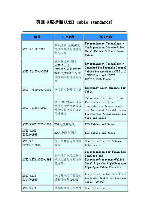
电线和电缆用热塑性绝缘体和护套测试方法
Methods of Testing Thermoplastic Insulations and Jackets for Wire and Cable
ANSI/ASTM D2655-2000
额定电压达到2000伏的电线和电缆交联聚乙烯绝缘材料规范(10.02)
ANSI/ASTM D4732-2002
电信电线和电缆用冷充填化合物规范
Specification for Cool-Application Filling Compounds for Telecommunications Wire and Cable
ANSI J-STD-042-2002
电缆的应急警报ge for Cable
ANSI T1.307-2003
电信.防火标准.设备组件的可燃性要求以及电线和电缆的火焰传播要求
Telecommunications - Fire Resistance Criteria - Ignitability Requirements for Equipment Assemblies and Fire Spread Requirements for Wire and Cable
ANSI/ASTM D1523-2000
工作温度90℃的电线和电缆用合成橡胶绝缘规范(10.01)
Specification for Synthetic Rubber Insulation for Wire and Cable, 90°C Operations (10.01)
ANSI/ASTM D2219-2002
ANSI/ASTM D4244-1995
重负载和超重负载丙烯腈丁二烯聚氯乙烯(NBR PVC)电线和电缆护套通用规范
Unit 6 Methods of Elevation
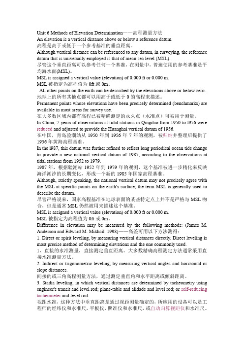
Unit 6 Methods of Elevation Determination——高程测量方法An elevation is a vertical distance above or below a reference datum.高程是高于或低于一个参考基准的垂直距离。
Although vertical distance can be referenced to any datum, in surveying, the reference datum that is universally employed is that of mean sea level (MSL).尽管这个垂直距离可以参考任何一个基准,在测量中,普遍使用的参考基准是平均海水面(MSL)。
MSL is assigned a vertical value (elevation) of 0.000 ft or 0.000 m.MSL被指定为高程值为0ft或0m。
All other points on the earth can be described by the elevations above or below zero. 地球上的所有其他点都可以用高于或低于0的高程来描述。
Permanent points whose elevations have been precisely determined (benchmarks) are available in most areas for survey use.在大多数区域内都有高程已被精确测定的永久点(水准点)可被用于测量。
In China, 7 years of observations at tidal stations in Qingdao from 1950 to l956 were reduced and adjusted to provide the Huanghai vertical datum of 1956.在中国,青岛验潮站从1950年到1956年7年的观测,被归纳并整理后提供了1956年黄海高程基准。
ExovaWarringtonfire威灵顿消防集团
Exova Warringtonfire威灵顿消防集团Exova威灵顿消防集团为国际市场提供消防安全设计策略、消防产品检测及认证的全方位服务。
我们由专业工程师和科学家组成的专家团队一向以严谨和友好的服务闻名业界。
该防火测试实验室在英国,德国,意大利,加拿大,澳大利亚拥有多个防火测试实验室,在中东和亚太地区亦设立了多家办事处。
消防咨询服务涵盖消防安全工程设计、常规设计审核、火场勘查、风险评估以及消防安全管理的所有方面。
消防产品检测服务包括按多个国家(BS, EN, DIN, NF, ASTM, IMO, AS, NFPA, UL, IEC)及国际标准(ISO)进行的消防测试和评估。
Exova在英国皇家认可委员会的认可编号为UKAS0249,目前轨道车辆上需要机车防火材料需要BS6853:1999标准要求的,由Exova实验室进行测试并出具测试报告和证书,在整个轨道车辆的业界人员都得到非常高的认可,确保工厂和贸易商的产品进行测试的数据的真实性和权威性。
请资质认可的测试标准和项目请参考如下:-BS 476:PART 3: 2004 - External Fire exposure roof test-BS 476:PART 4:1970 - Non-combustibility test for materials-BS 476:PART 5: 1979 - Method of test of ignitability-BS 476:PART 6: 1989 - Method of test for propagation for products-BS 476:PART 7: 1997 - Surface spread of flame test for materials-BS 476:PART 11: 1982 - Method for assessing the heat emission from building materials -BS 476:Part 12:1991 - Ignitability of Products by Direct Flame Impingement-BS 476:Part 15:1992 - Method for measuring heat release of products - Cone Calorimeter-BS 6401 - Smoke density test-BS 6853: 1999: Annex B.1 - Toxicity test-BS 6853: 1999: Annex B.2 - Determination Of Weighted Summation Of Toxic Fume, R. Area Based Test Method.-BS 6853: 1999: Annex D.8.3 - Small Scale Smoke Test-BS 6853: 1999: Annex D.8.4 - Panel Smoke Test-BS 6853: 1999: Annex D.8.5 - Seating Smoke Test-BS 6853: 1999: Annex D.8.6 - Flooring Smoke Test-BS 6853: 1999: Annex D.8.7 - Cable Smoke Test-BS EN 13823 (SBI) - Single Burning Item Test-BS EN 1869 - Fire blanket test-BS EN 50268 (Superseded by IEC 61034)-BS EN 60695-11 Glow Wire test-BS EN 60695-12 Glow Wire test-BS EN 60695-13 Glow Wire test-BS EN ISO 1182 - Non-combustibility test.-BS EN ISO 11925-2 - Ignitability when subjected to Direct Flame Impingement-BS EN ISO 1716 - Bomb Calorimeter-BS EN ISO 4589: Part 2 - Oxygen Index Test-BS EN ISO 4589: Part 3 - Elevated Oxygen Index Test-BS EN ISO 4589: Part 3 – Appendix A Temperature Index Test-BS EN ISO 9239-1 – Radiant Panel Floor Test-BS 5803 (loft Insulation)-NFP 92-501 - Epiradiateur-NFP 92-503 - Electric Burner Test-NFP 92-504 - Rate of Spread of Flame test-NFP 92-505 - Dripping Test-NFX 10-702 - Smoke Density Test-NFX 70-100 - Mass Based Toxicity Test-F-Rating summary report in accordance with NFF 16-101-DIN 4102: Part 7 – Roof test-ISO 5659-2: 2006 - Determination of Specific Optical Density-ISO 5660-1 - Cone Calorimeter-ISO 9705:1993 - Full-scale room test for surface products.-ISO 5658 - Surface Spread of Flame Test.-EN 1869 - Fire blanket test-European Directive 95/28/EC: Annex IV-European Directive 95/28/EC: Annex V-IMO A.653 (16) As Amended By IMO Resolution MSC 61(67): Annex 1, Part 5-IMO Resolution A.652 (16) - Recommendation on Fire Test Procedures for upholstered furniture-IMO Resolution A 471 (Xll) as amended by A.563 (14) - Recommendation on test method for determining the resistance to flame of vertically supported textiles and films-IMO Resolution A.688 (17) - Fire Test Procedures for ignitability of bedding components.-IMO Resolution MSC 40(64) - Full-scale room test for surface products.-IMO Resolution MSC 61(67): Annex 1, Part 1 - Non-combustibility test.-IMO Resolution MSC 61(67): Annex 1, Part 2 - Smoke and Toxicity testMSC / Circ 1006-ASTM E648-03 – Radiant Panel Floor Test-ASTM E662-03 – Smoke Density Test-NES 711 – Smoke Density Test-NES 713 – Toxic Gas Emissions-NFX 10-702 - Smoke Density Test-NFX 70-100 - Mass Based Toxicity Test-BS EN 60684-2 fluorine content-ABD 0031 Smoke and toxicity-IEC 50267-2: Parts 1, 2 & 3 – Gas emission test-IEC 60754: Part 1 – Gas emission test-IEC 60754: Part 2 – Gas emission test-CERTIFIRE DTS 63 – Temporary Protective Coverings TestPackage includes all tests specified in DTS 63Mining Grating Test(In-house Test Procedure)PAS 017 Amended 14 September 1999Clause 10.1 - Flammable Liquid TestMudguard Testing -(In-house Test Procedure)WFR TP 002: January 1999BS 476:PART 3: 2004External Fire exposure roof testDD ENV 1187: Test 1DD ENV 1187: Test 2DD ENV 1187: Test 4ENV 1187 Test 4 / BS 476: Part 3: 2004 combination testDIN 4102: Part 7NORD TEST NT 006UIC 564-2 Appendix 5UIC 564-2 Appendix 11UIC 564-2 Appendix 12UIC 564-2 Appendix 13CEN TS 45545-2 Annex A CEN TS 45545-2 Annex BAnnex A with Annex B packageCEN TS 45545-2 Annex C (Smoke and Toxicity Chamber Test)ISO 5659-2 in one mode only (as required in prCEN TS 45545-2 where no toxicity measurement is required)IEC 332-1 - Small Scale Cable Propagation TestIEC 50267-2: Parts 1, 2 & 3 – Gas emission testIEC 60754: Part 1 – Gas emission testIEC 60754: Part 2 – Gas emission test以上Exova威灵顿实验室相关资料,由南京睿督*************)公司提供。
Crank–Nicolsonmethod

Crank–Nicolson method From Wikipedia, the free encyclopediathen, letting , the equation for Crank–Nicolson method is a combination of the forward Euler method at and the backward Euler method at n + 1 (note, however, that the method itself is not simply the average of those two methods, as the equation has an implicit dependence on the solution):The function F must be discretized spatially with a central difference.Note that this is an implicit method: to get the "next" value of u in time, asystem of algebraic equations must be solved. If the partial differentialequation is nonlinear, the discretization will also be nonlinear so thatadvancing in time will involve the solution of a system of nonlinear algebraicequations, though linearizations are possible. In many problems, especiallylinear diffusion, the algebraic problem is tridiagonal and may be efficientlysolved with the tridiagonal matrix algorithm, which gives a fast directsolution as opposed to the usual for a full matrix.The Crank–Nicolson method is often applied to diffusion problems. As anexample, for linear diffusion,whose Crank–Nicolson discretization is then:or, letting :which is a tridiagonal problem, so that may be efficientlysolved by using the tridiagonal matrix algorithm in favor of amuch more costly matrix inversion.A quasilinear equation, such as (this is a minimalistic exampleand not general)would lead to a nonlinear system of algebraic equationswhich could not be easily solved as above; however, it ispossible in some cases to linearize the problem by usingthe old value for , that is instead of .Other times, it may be possible toestimate using an explicit method and maintainstability.The Crank–Nicolson method is often applied to diffusion problems. As an example, for linear diffusion,whose Crank–Nicolson discretization is then:or, letting :which is a tridiagonal problem, so that may be efficiently solved by using the tridiagonal matrix algorithm in favor of a much more costly matrix inversion.A quasilinear equation, such as (this is a minimalistic example and not general)would lead to a nonlinear system of algebraic equations which could not beeasily solved as above; however, it is possible in some cases to linearize theproblem by using the old value for , that is instead of .Other times, it may be possible to estimate using an explicitmethod and maintain stability.。
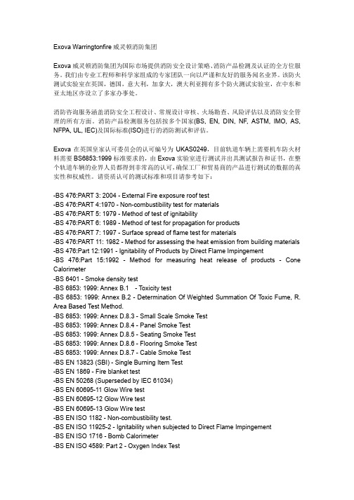
CONECALORIMETRY-...
CONE CALORIMETRYThe Cone Calorimeter has become a standard bench scale model of early flaming. In particular, it replicates the penetrative burning seen as fire burns into a specimen. It is used as a standard test and as a research tool to understand the burning characteristics and decomposition/combustion of polymers under a range of conditions. In addition to normal, standard test measurements, a range of special research tools are available including techniques to probe into the flame and decomposition zones and extract samples for analysis under both normal and restricted burning conditions.IMO Lateral Ignition and Flame Spread Test/Spread of Flame Apparatus (IMO-LIFT). This uses a large (1.0 x 0.3 m) area of sample which is exposed to a radiant panel, giving data on both time to ignition and rate of surface flame spread. It provides the data in a robust and repeatable way, and in addition to classifying the fire safety of products for the shipping, it has found wide use as a research tool in fire science and modelling.Combustion Mass Loss and effluent analysis. In addition to thermogravimetric and differential thermal analysis the laboratory has a special furnace for controlled decomposition and burning of small samples of polymeric materials under a range of fire conditions to study their burning behaviour fom mass loss and residue analysis.Other Standard Tests. In addition to our specialised research equipment, UCLan also have a number of ISO, EN, BS and ASTM standard tests for ignitability, flammability, and heat release determination. These can be modified for use in research programmes but are also available as standard tests so that materials and product behaviour can be determined in a standard manner and results directly related to the requirements of industry and regulators.Cone calorimetry (ISO 5660)A very well-established tool, providing data on surface ignition and penetrative burning.This has become the established small-scale standard for measuring the rate of heat release and the effective heat of combustion from a burning polymer under a controlled radiant heat source (ISO 5660 part 1). Heat release rate is the major cause of fire spread and growth, and the timing and magnitude of the peak rate of heat release (PRHR) and the short term (e.g. 3 minute) average rates of heat release are the single most important factor in predicting fire growth rate. The cone is established as the principal technique for the measurement of a number of fire and flammability hazard parameters for early or well-ventilated fires. The cone calorimeter can also be used to determine smoke generation (ISO 5660 part 2).The apparatus consists essentially of a conical electric heater (preset to 10 - 100 kW m-2) delivering uniform radiance to the sample (100 mm x 100 mm x up to 50 mm thick). The sample is mounted on a load cell recording its mass during the experiment. A spark is used to ignite flammable vapours. Air passes through the apparatus and tests are typically carried out under very well ventilated conditions (a modified cone calorimeter is available for studies in oxygen depleted environments, see below). The fire effluent gases travel upward into an instrumented hood system from where gas samples are collected.The cone calorimeter measures heat release on the basis of oxygen consumption calorimetry. This is based on the fact that the heat output from many combustible materials including most natural and synthetic plastics, rubbers and textiles is almost always a constant 13.6 kJ per gram of oxygen consumed. Other gas measurements, such as carbon monoxide and carbon dioxide concentrations are made, together with measurement of smoke density. The cone calorimeter experimental conditions are usually characterised by the following parameters:Output data are recorded for mass loss, for oxygen, carbon monoxide and carbon dioxide concentrations, for smoke density and fire effluent flow as a function of time. The raw data is manipulated and heat release rates and effective heats of combustion are calculated together with averaged data calculated by oxygen consumption calorimetry. Fire gas and smoke yields per gram of sample burnt are also calculated. Typical output summaries may include:。
电力变压器短路承受能力试验相电流精确测量方法
电力变压器短路承受能力试验相电流精确测量方法%何东升1,许呈盛2,刘光祺",罗海凹1,丁晓军1(1.国家智能电网输配电设备质量监督检验中心,广东东莞523325;2.广东工业大学,广东广州 510006;3.云南电网有限责任公司电力科学研究院,云南昆明650217)摘要:介绍了变压器短路试验的基本情况和标准对短路试验相电流测量的规定 要求。
针对目前三角形联结绕组的变压器相电流无法直接测量的问题,提出了一种等效 线路测量方法。
通过公式推导和理论计算,搭建电路图,实现动态系统建模、仿真和分 析,并对此测量方法进行了应用验证。
所提测量方法符合标准要求,且提高了检验效率 和测量精度,保证了检测的公正性和故障定位的有效性,具有一定的推广和借鉴意义。
关键词#变压器,■短路试验,■相电流测量,■测量方法中图分类号:TM 406文献标志码:B文章编号#2095-8188(2018)14-0042-04 DOI #10.16628/j. cnki. 2095-8188. 2018. 14. 008何东升( 1978—),男,高级工程师,主 要从事高、中、低压 电力电器产品的试 验、认证与设备研 发。
Phase Current Accurate Measurement Metliod of Power TransformerShort Circuit Withstand Capability TestHE Dongsheng1,XU Chengsheng2,LIUGuangqi3,LUOHaiao1,DINGXiaojun1(1. China National Q uality Supervision and Testing Center for Smart G rid Transmissionand D istribution E quipm ent,Dongguan523325,C h in a;2.Guangdong University of Technology,Guangzhou510006,C h in a;3.E lectric Power Research In s titu te,Yunnan Power Grid Co.,L td.,Yunnan650217,C hina)Abstract :This paper introduced the basic conditions of transformer short-circuit test standard for phase current m easurement of short-circuit test. In view of the problem that the transformer phasecurrent in triangle junction winding ccn not be measured directly without external lead terminal,ameasurementmethod of equivalent circuit was proposed,which,through formula derivation and theoretical calculation,constructsthe circuit diagram,realizes the dynamic system modeling,the simulation and the analysis,and carries on theapplication verification to this m easuring method. This measurement method meets the standard requirements,andimproves the test efficiency and measurement accuracy,and ensures the fairness and effectiveness of the detection ofthe fault location,it has certain promotional and reference significance.Key words:transform er $short-circuit test $phase current measurement ;measurement method0引言电力变压器突发短路试验是衡量变压器抗短 路能力的一项重要测试项目,短路过程中流经绕组的电流比额定电流要大十几倍甚至几十倍,试验过 程中在漏磁场的作用下产生巨大的短路电动力,其 力会驱使绕组变形、撑条垫块移位,或者直接导致 机械部件和绝缘部件断裂甚至爆炸,这对变压器的许呈盛(1994 一),男,硕士研究生,研究方向为非晶合金配电变压器的抗短路能力提升方法 刘光祺(1986—),男,工程师,主要从事高电压研究工作。
Supercriticalflu
ReviewSupercritical fluids technology for clean biofuel productionDongsheng Wen a,*,H.Jiang a ,Kai Zhang ba School of Engineering and Materials Science,Queen Mary University of London,London E14NS,UK bState Key Laboratory of Heavy Oil Processing,China University of Petroleum,Beijing 102249,China Received 14April 2008;received in revised form 16September 2008;accepted 18September 2008AbstractBiofuels are liquid or gaseous fuels that are predominantly produced from biomass for transport sector applications.As biofuels are renewable,sustainable,carbon neutral and environmentally benign,they have been proposed as promising alternative fuels for gasoline and diesel engines.This paper reviews state-of-the-art application of the supercritical fluid (SCF)technique in biofuels production that includes biodiesel from vegetable oils via the transesterification process,bio-hydrogen from the gasification and bio-oil from the lique-faction of biomass,with biodiesel production as the main focus.The global biofuel situation and biofuel economics are also reviewed.The SCF has been shown to be a promising technique for future large-scale biofuel production,especially for biodiesel production from waster oil and pared with conventional biofuel production methods,the SCF technology possesses a number of advantages that includes fast kinetics,high fuel production rate,ease of continuous operation and elimination of the necessity of catalysts.The harsh operation environment,i.e.the high temperature and high pressure,and its request on the materials and associated cost are the main concerns for its wide application.Ó2008National Natural Science Foundation of China and Chinese Academy of Sciences.Published by Elsevier Limited and Science in China Press.All rights reserved.Keywords:Supercritical fluids;Biomass;Transesterification;Biofuel;Hydrogen;Biodiesel;Gasification;Liquefaction1.IntroductionConcerns about global climate change due to the emis-sion of greenhouse gases,and the projected decline in world oil production has placed energy as the single most important problem facing humanity in the next 50years [1].Securing clean,affordable energy for the long term becomes one of the biggest challenges in modern societies.Increasing use of energy generated from renewable resources including biomass,wind energy,hydroelectric power and solar energy will become viable,where geo-graphical and climatic prerequisites are favorable.Such regions,however,seldom coincide with areas of high energy consumption,i.e.industrial and city regions witha high population density.Various sources including hydrogen,biofuels and batteries have been proposed as secondary energy carriers for the future transport sector.To become replacement fuels for the future transport sector,the candidates would have to meet a number of cri-teria that include (1)abundance with enough resources that could replace petroleum-based fuels in the long term;(2)zero or low carbon emission with minimum detrimental effect to the environment;(3)applicable to most running vehicles based on existing infrastructures;and (4)econom-ically viable.Hydrogen fuel is difficult to become a reality in the short term as today’s production is dependent on crude oils or natural gas as raw material,or electricity that are from fossil fuels,together with other significant tech-nology and economic challenges in hydrogen storage,transportation and utilization.Electric and hybrid vehicles are proposed as more viable alternatives to hydrogen vehi-1002-0071/$-see front matter Ó2008National Natural Science Foundation of China and Chinese Academy of Sciences.Published by Elsevier Limited and Science in China Press.All rights reserved.doi:10.1016/j.pnsc.2008.09.001*Corresponding author.Tel.:+442078823232;fax:+442089831007.E-mail address:d.wen@ (D.Wen)./locate/pnscAvailable online at Progress in Natural Science 19(2009)273–284cles for transportation,particularly in the short term [2,3];however they suffer another serious problem:limited resource of heavy metals needed for batteries.Biofuels are liquid or gaseous fuels for the transport sector that are predominantly produced from biomass.Biomass has been recognized as a major world renewable energy source to supplement declining fossil fuel resources [4]and cur-rently supply $10%of our global energy needs with expected fast growth in the near future,i.e.it would account for as much as 50%of the US’s total energy con-sumption by 2050[5].Biofuels can be produced from a variety of bio-feedstocks,they are renewable,sustainable,biodegradable,carbon neutral for the whole life cycle and environmentally friendly so as to encourage green fields and the agriculture industry,as well as applicable to run-ning vehicles with or without slight modifications.Various bio-origin fuels including bio-ethanol,biodiesel and bio-hydrogen appear to be attractive options for the future transport sector.The decline of fossil fuel resources and the increasing price of petroleum products have led to a major interest in expanding the use of biofuels.This has been reflected by the US’s commitment of threefold increase in bioenergy in 10years time,and the EU’s new biofuel targets of reach-ing a minimum share of $5.75%of the transport fuel mar-ket by the end of 2010[6].The shares of alternative fuels,biofuels,hydrogen and natural gas compared to the total automotive fuel consumption in the world are shown in Fig.1as a futuristic view [7].The production of biofuels is expected to rise steadily in the next few decades.Conventionally,biofuel production is based on two routes:either thermochemical conversion or biochemical conversion,as illustrated in Fig.2.The thermochemical conversion route can be applied to wood,straw and refuse through the gasification,liquefaction and pyrolysis pro-cesses to produce syn-gas,syn-oil and biochemicals.Bio-chemical conversion predominantly refers to bio-ethanol and biodiesel production through acid and enzyme hydro-lysis and/or fermentation from different sets of feedstocks that include wood,wheat and sugar beet.In terms of abso-lute fuel costs,thermochemical conversion offers low-cost products with some mature technologies.Biochemicalroutes are more expensive.With strong competition from the global fuel market,there is a growing trend towards employing modern technologies for efficient biomass con-version.The supercritical fluids (SCFs)technique is one of the most promising ones.2.Supercritical fluids techniqueIn general,when a mixture of liquid and gas at equilib-rium is heated,thermal expansion causes the liquid to become less dense.At the same time,the gas becomes den-ser as pressure increases.At the critical point,the densities of the two phases become identical and the distinction between them disappears.A supercritical status is defined as the fluids’temperature and pressure above its critical temperature,T c ,and critical pressure,P c .In the gas–liquid transition regime,the SCF presents a combination of prop-erties of gases and liquids,which makes them very suitable for the development of new processes that cannot be car-ried out with conventional liquid or gaseous fluids.The critical parameters of some common fluids are illustrated in Table 1.Due to the creation of a homogeneous reaction environ-ment,supercritical fluids possess a number of unique advantages including increased species mixing,heat and mass transfer,fast reaction typically at a few minutes level,are environmentally benign,and have good scalability,as well as being simple and easy for continuous production.The unique properties at supercritical conditions,i.e.strong dependence of the solubility of a material in a super-critical fluid to its density and good contact between oxi-dants and reactants,make SCFs ideal for separation and extraction of useful products and for oxidation of organic materials.However,these also have some limitations related to the harsh operation environment and their effect on the materials.Corrosion and salt deposition are the two main challenges for most of the industrial applications,especially for supercritical water (SCW)[10–12].SCW is favorable for corrosion due to the presence of high pH val-ues,high concentrations of dissolved oxygen,ionic inor-ganic species and high temperature–pressure variations.Metal oxides can be formed due to the reduced salt solubil-ity,which could form stable solid particles that cause equipment fouling,plugging and erosion.A numberofFig.1.Prediction of shares in the automobile market for three alternative fuels[7].Fig.2.Conventional biomass conversion routes [8].274 D.Wen et al./Progress in Natural Science 19(2009)273–284plants could not meet their designed performance and some have been closed for these reasons[13].Besides these, the high energy intensity to reach supercritical status is another big problem for the SCF technology,which could be solved with better heat recycling and improved system design.Despite these limitations,the SCF technique has been proved to be an environmentally benign medium for a number of chemical and related processes in the last few decades.Many new processes and products including the fractionation of products,dyeing offibres,treatment of contaminated solids,production of powders in micro/ nanometer sizes and novel reactions[14,15]have also been developed using the unique physical and chemical proper-ties of supercriticalfluids.For the energy industry,super-criticalfluids techniques have been used for coal-fired power plants[16],direct liquefaction or indirect liquefac-tion through gasification process for manufacturing syn-thesized gas,synthesized oil and chemical products,as well as advanced nuclear systems.For a instace,supercrit-ical water reactors(SCWRs),have a high thermal efficiency of$45%in comparison with current light water reactors which have a thermal efficiency of$33%[17].More recently,there has been an emerging application of super-criticalfluids techniques for clean and high throughput biofuel pared with conventional thermo-chemical and biochemical methods,the SCF technology possesses a number of advantages such as a high fuel con-version rate,quick reaction,clean production,easy and continuous operation,and elimination of the necessity of catalysts.This paper will review state-of-the-art biofuel production using the SCF technique,with the main focus on biodiesel production through the transesterification pro-cess.Bio-hydrogen production through the gasification process and bio-oil production from the liquefaction pro-cess of biomass will also be reviewed shortly.3.SCFs for biodiesel production3.1.Biodiesel productionVegetable oil has been widely used for a long time.Even thefirst diesel engine,named by the German scientist, Rudolph Diesel,was successfully run on peanut oil$100 years ago.The thermo-physical properties of vegetable oil,mostly viscosity and volatility,however,limit its direct application on diesel engines.A general list of properties of vegetable oils from different sources is shown in Table2. The viscosity value for most vegetable oils is at a range of35–60cSt,which is much higher than that of standard diesel fuels($4cSt).This high viscosity can result in prob-lems in pumping and fuel spray processes such as the atom-ization and penetration effect.The low volatility of vegetable oils can result in a highflash point,which will produce a number of problems including injector choking, piston ring sticking,high carbon deposition,and lubrica-tion oil dilution and oil degradation[19].The reactivity of unsaturated hydrocarbon chains can also bring other problems.The combination of all these factors makes the direct application of vegetable oil unfeasible.There has been,however,a renewed interest in vegetable oil for the transport sector recently due to the increasing price of crude oil and environmental concerns.It could, in the long run,substitute some fraction of petroleum dis-Table1Critical property of various solvents[9].Solvent Molecular weight(g/mol)Critical temperature(K)Critical pressure(MPa)Density(kg/l) Carbon dioxide44.01304.17.38469Water18.02647.322.12348 Methane16.04190.4 4.60162Ethane30.07305.3 4.87203 Propane44.09369.8 4.25217 Methanol32.04512.68.09272Ethanol46.07513.9 6.14276Acetone58.08508.1 4.70278Table2Properties of the vegetable oils[18].Vegetable oil Kinematics viscosity(mm2/s)CetanenumberCloud point(°C)Pour point(°C)Flash point(°C)Density(kg/l)Lower heating value(MJ/kg)Peanut 4.9545–1760.88333.6 Soya bean 4.5451À71780.88533.5 Babassu 3.6634–1270.87531.8 Palm 5.76213–1640.88033.5 Sunflower 4.6491–1830.86033.5 Tallow––12996––Diesel 3.0650–À16760.85543.820%biodiesel blend 3.251–À161280.85943.2D.Wen et al./Progress in Natural Science19(2009)273–284275tillates.However,economically it is not a competitive fuel at the moment due to the lack of practical on-farm process-ing technology and relatively high associated cost.For meeting environmental and energy security concerns, acceptable alternative fuels for the transport sector have to demonstrate that they do not sacrifice the engines’oper-ating performance.Vegetable oils have to be modified to bring their combustion-related properties closer to their petroleum-derived counterparts.The fuel modification for vegetable oils is mainly aimed at reducing their viscosity and increasing their volatility.Dilution,micro-emulsion, pyrolysis(thermal cracking)and transesterification to bio-diesel have been frequently used.Among all these tech-niques,the most successful one is to convert vegetable oils to biodiesel through the transesterification process[20].Biodiesel is the methyl or ethyl ester of fatty acids made from virgin or used vegetable oils(both edible and non-edi-ble)and animal fat.Biodiesel has combustion-related prop-erties similar to those of petroleum diesel;it also operates in compression ignition(diesel)engines and requires very little or no engine modifications.Biodiesel can be blended in any proportion with petroleum diesel to create a biodie-sel blend or can be used in its pure form.It can be stored just like petroleum-derived diesel and hence does not require a separate infrastructure.The use of biodiesel in conventional diesel engines can result in substantial reduc-tion in emission of unburned hydrocarbons,carbon mon-oxide and particulate matters.In chemical terms,transesterification is the process of exchanging the alkoxy group of an ester compound by another alcohol.The reactions are often catalyzed by an acid or a base.Transesterification is crucial for producing biodiesel from biolipids.The transesterification process is the reaction of a triglyceride(fat/oil)with a bioalcohol to form esters and glycerol[19,21,22].The transesterification reaction can be initiated with or without a catalyst by using primary or secondary monohydric aliphatic alcohols hav-ing1–8carbon atoms,as shown below,TriglyceridesþMonohydric alcohol!GlycerinþMono-alkyland a typical transesterification process is schematically shown in Fig.3.For biodiesel production,the transesterification can be conducted in either the presence or absence of a catalyst. The usual catalysts used are alkalis(NaOH,KOH),acids (sulfuric acid,HCl)and enzymes(lipases).The kinetics of acid-catalyzed and alkali-catalyzed reactions has been well studied and these processes have been commercialized [23],and some reviews on biodiesel production are also available[18].The typical catalytic transesterification pro-cess includes the transesterification reaction,recovery of un-reacted reactants,purification of the esters,separation of glycerol and the separation of the catalyst from the reac-tants and products,as shown in Fig.3.Due to the need for vigorous stirring to mix the oil and alcohol and separate the catalysts after the reaction,the catalytic processes have a high production cost and are energy intensive[24,25].The supercriticalfluids technique can be used to synthe-size biodiesel through the transesterification of vegetable oils without using any pared to the conventional catalytic processes,the SCF technique possesses a number of notable advantages such as easy separation,fast reaction and being environmentally friendly.This is primarily because alcohols and oil can co-exist in a single phase under supercritical conditions.The increased solubility of organic matters and the homogeneous environment make the transe-sterification process pared with the catalytic transesterification process,relatively fewer investigations have been explored through the supercriticalfluids route. The research on the topic was pioneered in Japan[18,26–31],and recently it has enjoyed a sustained strong develop-ment in Europe[8,21,32–34],China[35–37]and India [24,38].Most of these studies were conducted under labora-tory conditions,and there is still a lack of consensus on the mechanisms of the reaction.Most of the transesterification methods via the SCF techniques are based on the batch pro-duction method[21,24,29,35];very few are based on the con-tinuous production of biodiesel based on aflow loop[37], whose development is still at the beginning.3.2.Biodiesel production from SCF transesterificationA number of parameters can affect the methyl ester yield during the transesterification reaction such as the reaction temperature and pressure,alcoholic types,molar ratio of alcohol to vegetable oil,residence time,water and free fatty acid content,solvents and catalysts,and operation modes. Examples of the influence of these parameters on the bio-diesel production are reviewedbelow.Fig.3.Basic scheme for biodiesel production viatransesterification.Fig.4.Biodiesel conversion from hazelnut kernel oil[32]. 276 D.Wen et al./Progress in Natural Science19(2009)273–2843.2.1.Temperature and residence time effectIt was observed that an increase in the reaction temper-ature,especially supercritical temperatures,had a favorable influence on the ester conversion.Fig.4shows a typical example of the relationship between the biodiesel conver-sion and the reaction temperature for hazelnut kernel oil at a molar ratio of vegetable oil to methyl alcohol of 1:41[32].Table 1shows that the critical temperature of metha-nol is 512.6K,there is a big jump in the conversion rate as the temperature increases from sub-supercritical conditions (503K)to the supercritical temperature.Nearly 100%con-version is achieved in about 6min.This is a significant achievement compared with the conventional catalytic transesterification processes,which generally take a few hours to reach equilibrium and are difficult to achieve a complete conversion.3.2.2.Alcohol effectVegetable oil can react with a number of alcohols.Fig.5illustrates the role of different supercritical alcohols in the fatty acid alkyl ester conversion from triglycerides [28].The experimental results illustrated that alcohols with shorter alkyl chains gave better conversions under the same reaction time.Nearly 100%yield of alkyl esters was obtained within 15min treatment with methanol,while it took $45min by ethanol and 1-propanol methods.Under a similar condition,supercritical 1-butanol and 1-octanol produced about 85%and 62%of alkyl esters,respectively,and the reaction reached a flat conversion rate of $60%after 20min for 1-octanol.As a consequence,the supercrit-ical methanol method has been widely investigated for bio-diesel production.Note that there is a big difference in the reaction time to reach the equilibrium status for the meth-anol reaction between different research groups (Figs.4and 5).This is common for all affecting parameters,although agreed qualitatively in general,quantitative results differ significantly among different research groups,which requires further extensive investigations.3.2.3.Molar ratio effectThe stoichiometric ratio for the transesterification reac-tion requires only 3mole of alcohol and 1mole of triglyc-eride to yield 3mole of fatty acid ester and 1mole ofglycerol.Various vegetable oils have been investigated and it was found that they can be transesterified at wide vegetable oil-alcohol molar ratios in supercritical alcohol conditions,ranging from 1:1to 1:50[18,29,32].Examples of the molar ratio effect are shown in Fig.6for batch bio-diesel production from cottonseed oil [32],and continuous biodiesel production from soybean oil based on the super-critical methanol method under 300°C and 32MPa condi-tions [37].It is evident that higher molar ratios can result in a larger ester conversion rate in a shorter time.For soybean oil,the conversion rate reached a plateau at a ratio of $40;further increase in the ratio did not help.Similar results have been obtained by other researchers [18,23,29].An optimized excess of the alcohol of $40is therefore gener-ally suggested in order to increase the yields of the alkyl esters and to facilitate its phase separation from the glyc-erol formed.3.2.4.Water and free fatty acids effectFor biodiesel production from the conventional cata-lytic transesterification reaction,the presence of water can consume the catalyst,reduce catalyst efficiency and cause soap formation and frothing,which increase the bio-diesel viscosity and make the glycerol separation difficult due to the formation of gels and foams [8].For catalytic reactions,the vegetable oils/fats used as a raw material for the transesterification should be water-free,or of extre-mely low concentration,i.e.below 0.06%,much lower than the allowable free fatty acids content [30,39,40].As most of the waste vegetable oils and crude oils generally contain water and free fatty acids,these problems may reduce the biodiesel production efficiency [41].For the supercritical methanol method,optimized oper-ation parameters have been found to be $350°C,$43MPa and residence time of $240s with a molar ratio of 42in methanol for transesterification of rapeseed oil to biodiesel fuel [29].Under supercritical conditions,free fatty acids in the oil could be simultaneously esterified.The water content effect on the yield of methyl esters by the supercritical methanol treatment was studied by Kusdiana and Saka [30]and compared with those from alkaline-and acid-catalyzed methods.Examples of water content and free fatty acid on the acid-,alkaline-catalyzed andsuper-Fig.5.Alcohol effect on biodiesel conversion[28].Fig.6.Effect of molar ratio on yield of methyl ester [32,37].D.Wen et al./Progress in Natural Science 19(2009)273–284277critical transesterification of vegetable oil are shown in Figs.7and 8.For acid catalytic reactions,as little as 0.1%of water addition could lead to significant reduction of the yield of methyl esters;the conversion was reduced to only $6%when $5%of water was added.A similar trend was also observed for the alkaline-catalyzed meth-ods.However,the amount of water added into the reaction system did not have any significant effect on the conversion in the supercritical methanol method;and the presence of water positively affects the formation of methyl esters.In addition,compared with the alkaline-catalyzed method,a higher yield could also be obtained from free fatty acids (Fig.8).The water-added supercritical methanol method has another feature of easier product separation,since glycerol,a co-product of transesterification,is more soluble in water than in methanol.It appears that the supercritical method is specially good for converting a variety of resources with large contents of water and free fatty acid to biodiesel,which include crude vegetable oil,waste cooking oil and animal fats.3.2.5.Co-solvent effectFor most of the supercritical methods of biodiesel pro-duction,the reaction requires temperatures of 340–400°C and pressures of 20–70MPa,which is energy intensive.Such harsh operation conditions also lead to high produc-tion costs and material requirements.Various methods including co-solvents and catalysts have been investigated to reduce the reaction temperature and pressure while achieving similar conversion rates.It is known that the solubility of methanol decreases at supercritical conditions,being closer to that of vegetable oil at the appropriate temperature and pressure [42].Some reports also show that the solubility of vegetable oils in methanol increases at a rate of 2–3%per 10°C increase [39].It would be of great interest from a practical point of view to investigate the effect of a co-solvent.This could not only increase the mutual solubility of methanol and vegeta-ble oil at low reaction temperatures,but also possibly decrease the critical point of methanol,and allow the super-critical reaction to be carried out under milder ing propane as the co-solvent,a study of the transest-erification of soybean oil in the supercritical methanol was investigated [35].Critical points for the binary system were determined by the content of propane in the binary system,which was found to decrease with increasing molar ratio of propane to methanol.The effect of propane on the conver-sion of soybean oil to methyl esters as biodiesel fuels is shown in Fig.9.It is obvious that using propane as a co-sol-vent,the temperature can be reduced significantly,i.e.330°C for methanol only and 280°C at propane-to-metha-nol molar ratio of 0.1,to reach a full conversion.As pro-pane is easy to add and separate,the reduction of reaction temperature could make it viable for industrial applications.3.2.6.Catalyst effectFor the conventional catalytic transesterification pro-cess,catalysts are classified as three types,alkali,acid and enzyme.Most of the reactions can be quickly preceded without the need of a catalyst under supercritical methanol and ethanol conditions.However,a few catalysts have also been introduced under such a condition in order to lower the reaction temperature and pressure,as outlined below.Calcium oxide (CaO)has been known to catalyze reac-tions that require a base site.It is not dissolved in the reac-tion medium,and the transesterification reaction is heterogeneous.The roles of CaO in the supercritical transe-sterification of sunflower seed oil to biodiesel were investi-gated by Demirbas [33].It was found that the addition of CaO could considerably improve the transesterification reaction.The experimental results are shown in Fig.10for a temperature of 525K and a molar ratio of methanol to sunflower oil:41:1.It can be seen that thetransesterificationFig.7.Yields of methyl esters as a function of water content[30].Fig.8.Yields of methyl ester as a function of fatty acids content[30].Fig.9.Biodiesel conversions of propane and methanol under supercritical conditions [35].278 D.Wen et al./Progress in Natural Science 19(2009)273–284rate increases evidently with increasing CaO concentrations,and the reaction time of the yield reaching plateaus of methyl ester decreases with increasing catalyst concentrations.Temperatures and molar ratios were also found to have great influences on the catalytic supercritical transesterifica-tion.Sunflower oils could be fully converted to biodiesel in 6min under optimum conditions,i.e.at a temperature of $525K with 3wt%CaO and 41:1methanol/oil molar ratio.Of note is that the catalytic transesterification ability of CaO was quite weak under ambient temperature,i.e.the yield of methyl ester was only about 5%in 3h at 335K.CaO appears to be a good catalyst under supercritical conditions.Enzymatic reactions in supercritical carbon dioxide have been considered to be a practical way of achieving a better biofuel production rate.The requirement on power con-sumption and equipment is much lower for CO 2SCFs than for supercritical methanol and ethanol (Table 1).The sep-aration can also be easily achieved by the reduction of pres-sure,as the products and the enzyme do not dissolve in carbon dioxide at room conditions.Such an enzymatic reaction in supercritical carbon dioxide has been explored and compared with non-catalytic supercritical methods [24].One example of experimental results is shown in Fig.11for the reaction at 45°C with 3mg of enzyme.Enzyme reactions in supercritical carbon dioxide took a much longer time and achieved only very low conversions (27–30%),whilst high conversion rates (80–100%)were typically achieved under supercritical methanol and etha-nol conditions [29,32].An improved reaction of supercriti-cal CO 2was developed for both edible and non-edible oils,and a maximum conversion of less than 70%can be obtained after several hours of reaction [43].Though withlow biodiesel conversions,further investigation of the enzyme’s effect on the total energy consumption and bene-fit is still needed to assess this method.3.2.7.Continuous productionMost of the biodiesel production via supercritical transe-sterification is based on the batch-type process.As the supercritical methanol method requires a high temperature of 350°C and a pressure of 45MPa,and in addition,as a large amount of methanol is necessary,it generally involves high labor cost,unreliable production and relatively longer time.It would be very beneficial to operate under continu-ous production conditions.A few continuous production systems have been developed for catalytic transesterification processes,which have resulted in increased production effi-ciency and quality of biodiesel [44–47].Recently,He et al.[37]reported a continuous produc-tion process for soybean oil conversion to biodiesel through the supercritical methanol method.The experiments were operated in a 75ml tube reactor that supplied continuous flow of soybean oil and methanol under molar ratios from 6:1to 80:1.After the reaction,the product was cooled to room temperature,and then the crude methyl esters were obtained in a separate vessel.Similar to the supercritical batch operation,it was observed that increasing the molar ratio,reaction pressure and reaction temperature enhanced the production yield effectively.However,there is also a critical value of residence time at high reaction tempera-ture,and the production yield will decrease if the residence time surpasses this value.Some side reactions of unsatu-rated fatty acid methyl esters (FAMEs)also occurred when the reaction temperature was over 300°C,which led to a big loss of the material under a pressure of 32MPa and a molar ratio of 40:1as is shown in Fig.12.Under the opti-mal reaction condition,only a maximum production yield of 77%was observed,primarily due to the reactions of unsaturated FAMEs at high temperature.3.3.Reaction mechanism of transesterificationIt was observed in many experiments that fatty acids present in the vegetable oil can be successfully converted to methyl esters under supercritical methanolconditionsFig.10.Effect of CaO content on methyl ester yield[33].Fig.11.Biodiesel synthesis from supercritical CO 2[24].Fig.12.Continuous synthesis of methyl esters from soybean oil [37].D.Wen et al./Progress in Natural Science 19(2009)273–284279。
A Method for Detecting the Exposure of a
A Method for Detecting the Exposure of aSecret Key in Key-Insulated SchemeNo Author GivenNo Institute GivenAbstract.Dodis et al proposed a key-insulated signature scheme in2003.In the scheme,total lifetime of a certificate is divided to time pe-riods and different secret keys are used for each time period.The mastersecret key is stored in the physically secure device and is not used forsigning directly.The different secret keys are used for signature in eachtime period and they are refreshed by a computation with the masterkey.Therefore,the scheme can minimize the damage caused by a se-cret key’s exposure.However,it can not protect the user from the secretkey’s exposure perfectly.We propose a method which can detect even asingle illegitimate signature due to the exposure of a secret key in thekey-insulated scheme.The method uses the one-time hash chain basedon NOVOMODO and the counter.And it requires small modification oftraditional PKI.The method can prevent the users from compromisinga secret key effectively in the key-insulated signature scheme.Keywords.key-insulated signature,one-time hash chain,NOVOMODO1IntroductionPKI(Public Key Infrastructure)is a widespread and strong technology for pro-viding the security(integrity,authentication,and non-repudiation)using public key techniques.The main idea of PKI is based on the digital certificate that is a digitally signed statement binding an entity(user or authority)’s identity information and his public key by CA(Certificate Authority)’s secret key.If the entity’s secret key is compromised or the entity’s identity information is changed,the entity makes a request to the CA for revoking its own certificate. The information whether the certificate is revoked or not is called CSI(Certifi-cate Status Information)and CRL(Certificate Revocation Lists)is one of the most well-known methods for CSI[2,7,13].CRL size and communication cost The CRL system has an advantage of its simplicity,however,it has a disadvantage of high communication cost between the user and the CA’s Repository(or Directory)storing the CRL.Therefore, in order to reduce the size of certificate revocation list(communication costs), computation cost and storage amounts,various methods have been suggested up to date.These are Delta-CRL,CRL DP(Distributed Points),Over-issued CRL, Indirect CRL,Dynamic CRL DP,Freshest CRL,CRT(Certificate Revocation Trees),NOVOMODO,Authenticated Directory et al[1,2,5–7,9,11–14,16].2No Author GivenOCSP and computation cost If the client or user needs very timely CSI, an online certificate status service such as the OCSP(Online Certificate Status Protocol)is more convenient than the off-line method such as CRL et al[9].In OCSP,since the client does not need to download a CRL from the CA’s Repos-itory,the high communication cost between the client and the CA’s Repository and the storage spaces for storing the CRL are not required.However,if the CSI requests are centralized to an OCSP Responder,the OCSP Responder can have a risk of DoS(Denial of Service)attacks[15].In order to reduce the risk of DoS attacks,the OCSP Responder can pre-produce a signed value for responses in a short time.However this may allow a possibility of the replay attacks[15,16]. T-OCSP and D-OCSP To reduce the overload of single OCSP Responder in “T-OCSP(Traditional-OCSP)”,“D-OCSP(Distributed-OCSP)”is introduced [4,15].In D-OCSP,if distributed OCSP Responders have the same secret key, the possibility of OCSP Responder’s secret key exposure is very high[16].There-fore,in the general D-OCSP model,each OCSP Responder has a different secret key and clients must have all of the OCSP Responder’s certificates for verifying CSI response of OCSP Responders.This gives an increase of storage amounts consumption or communication costs for acquiring the OCSP Responder’s cer-tificates.For solving this problem,the method of single public key was proposed in D-OCSP-KIS(Distributed OCSP based on Key-Insulated Signature)by Koga and Sakurai[15].Also for solving the problem that the length of the single pub-lic key is in proportion to the number of OCSP Responder in D-OCSP-KIS, Daehyun Yum and Piljoong Lee proposed the D-OCSP-IBS(Distributed OCSP based on Identity-Based Signature)that the length of the single public key is constant and short[4].In addition,a method for detecting the exposure of an OCSP Responder’s session secret key in D-OCSP-KIS was proposed by Young-gyo Lee et al[19,20].Our Contributions However,the study for preventing the exposure of a user’s secret key is hardly accomplished up to date.Dodis et al proposed a key-insulated signature scheme at2003in[17,18].In the scheme,the master secret key is stored in the physically secure device and not used for signing directly.Total lifetime of the master secret key is divided into time periods and the different secret keys refreshed by the master key are used for each time period.Therefore the scheme can minimize the damage caused by the secret key’s exposure but can not protect the user from the secret key’s exposure in a time period perfectly. Just a single illegitimate signature by the exposure of a secret key can give extensive damage to the user in E-business or E-commerce.In this paper,we propose a method that can detect even a single illegitimate signature caused by the exposure of a secret key in the key-insulated scheme.The method uses the one-time hash chain based on NOVOMODO and the counter.The method can prevent users from compromising the secret key effectively in the key-insulated signature scheme.The rest of this paper is organized as follows.In section2,we present the key-insulated signature scheme and NOVOMODO.In section3,we propose a method for detecting the exposure of a secret key in the key-insulatedLecture Notes in Computer Science3 scheme.In section4,we analyze the proposal in detail.In section5,we show the characteristics of proposal and compare the proposed method to other methods. Finally,in section6,we conclude our paper.2Key-insulated signature scheme and NOVOMODOIn this section,we present the key-insulated signature scheme proposed by Dodis et alfirst and show Micali’s NOVOMODO that our proposal based on.2.1Key-insulated signature schemePublic key: registered in a central location(PK, SK*, SKInitial secret key: stored in insecure deviceSecret keysTime periodsFig.1.The concept of key-insulated signature scheme In the key-insulated signature scheme,the master secret key(SK*)is stored in the physically secure device(PSD)and not used for signing directly.Total lifetime of the master secret key is divided into time periods and the different secret keys refreshed by the master key are used for each time period as shown in Fig.1.The secret key(SK i)stored in the insecure device is refreshed at discrete time periods via interaction with the physically secure device which stores the master secret key.Therefore the scheme can minimize the damage caused by the secret key exposure until the secret key is changed.The key-insulated signature scheme needs a5-tuple of poly-time algorithms (Gen,Upd*,Upd,Sign,Vrfy)such that:–Gen:the key generation algorithm–Upd*:the physically secure device key-update algorithm–Upd:the user key-update algorithm4No Author Given–Sign :the signing algorithm–Vrfy :the signing verification algorithmAt first,a user generates (P K,SK ∗,SK 0)using Gen (1k ,N )and publishes PK in the central location.The user stores SK*in the physically secure device and stores SK 0in the general device.SK 0is used for signing during the time period 0.When a time period (if the secret key is SK i )is finished,the user gets SK i,j from the secure device using Upd ∗(i,j,SK ∗).The user computes thenext time period’s secret key SK j =Upd (i,j,SK i ,SK i,j )using SK i and SK i,j .Sign algorithm is used for signing a message M (Sign sk i (i,M )→i,s )and Vrfy algorithm is used for verifying the signature s of M (V rfy P K (M,<i,s >)→b )[17,18].After computing SK j ,the user erases SK i and SK i,j .SK j is used for signing a message during the time period j without further access to the physically secure device.Therefore the scheme can minimize the damage caused by the secret key’s exposure.However the scheme cannot protect the user from the exposure of user’s secret key in a time period perfectly.If the secret key (SK i in Fig.1)of a time period is exposed incidentally,it can be used for signing by an attacker acquiring it until it is changed (SK j in Fig.1).Therefore the key-insulated sig-nature scheme can minimize the damage caused by the secret key’s exposure but can not protect the user from the secret key’s exposure perfectly.2.2NOVOMODO validity target ),,,,,,(1365Y X V S I SN PK Sig Cert user SK user CA revocation targetFig.2.The structure of certificate in MOVOMODOIn NOVOMODO,a user’s certificate Cert user includes two 20-byte (160-bit)hash values in addition as shown in Fig.2.The one (X 365)is used as “validity tar-get”and the other (Y 1)is used as “revocation target.”These values are produced by applying one-way hash function to two different 20-byte values randomly se-lected in CA.When the time interval is one day,The value X 365is computed by 365hashing operations from X 0:X 1=h (X 0),X 2=h (X 1),...,X 365=h (X 364);and Y 1by 1hashing operation from Y 0:Y 1=h (Y 0).The CA keeps secretly the initial values X 0,Y 0and all the intermediate values X i .The CA releases the corresponding intermediate hash value to each user as a certificate’s “validityLecture Notes in Computer Science5 proof”(X i)or“revocation proof”(Y0)at initial time of each interval.In E-business or E-commerce based on PKI,the verifier getting the user’s certificate and corresponding hash value compares two values using the hash function.If the result of comparison is the same,the verifier gets the message authentica-tion and integrity concerning the released hash value(X i or Y0)periodically and confirms the user’s certificate status by the hash value[14].3A method detecting the exposure of a secret key in the key-insulated signature schemeAs we mentioned earlier,the key-insulated signature scheme can minimize the damage caused by the exposure of a secret key but can not protect the user from the exposure of a secret key perfectly.Therefore,in this section,we propose a method that detects even a single illegitimate signature by the exposure of a secret key of user.This proposal uses the one-time hash chain based on NOVO-MODO and the counter.And its framework(includes the certificate format)is similar to general PKI.3.1RequirementsOur proposal has some requirements as follow.1.Both the user’s signature and the verifier’s certificate status validation(usingOCSP)are established by1:1in real time.2.The user’s certificate includes a hash value(of20bytes)of“detection mark”for detecting the own secret key’s exposure.3.2Proposal[Initial procedure:the user’s certificate issuance by CA]1.In this proposal,the user’s secret key is restricted by the number of sig-natures.Let K be the total number of signature usages for a user.For an example,K is10,000if each user’s certificate is expired after10,000signing operations.Thus,the certificate of the user is expired after10,000certificate status validations.The user computes Z0by10,000hashing operations from random input value Z K using h as follows.Z K h→Z K−1h→...Z i...h→Z1h→Z02.The user sends the own public key,the own identification information,andthefinal hash value,Z0safely to CA for the request of own certificate is-suance.6No Author GivenverifierStep 1011Z h Z h Z h Z h Z i K K o o o o 0m before C ),,(0Z PK user PK Fig.3.The procedure of certificate issuance by CA3.The CA issues the user’s certificate Cert user by using own secret key.In Cert user ,the hash value Z 0is also included as follows.SN is the serial number of certificate and V represents the validity period.I and S denote issuer and subject of certificate,respectively.And the CA sets the counter C before for user to 0.The counter C before is stored and managed in CA.Cert user =Sig SK CA (P K user ,SN,I,S,V,Z 0)C before ←04.The user stores his own master secret key,the input value and all interme-diate values of step 1in PSD securely.[Service procedure :signature and certificate status validation]1.When the user signs,he sends his own certificate and the hash value Z i with the signed message M to the verifier.The Z i is taken out from PSD and delivered in the order of Z 1,Z 2,Z 3,...,Z K .M,Sig SK user (M ),Cert user ,Z i2.After receiving the signed message from user,the verifier requests the user’s certificate status information to CA.Then he also delivers the user’s certifi-cate and the hash value Z i with the OCSP request.OCSP request,Cert user ,Z iLecture Notes in Computer Science 7Step 3:C 1? before now CFig.4.The procedure of signature and certificate status validation3.When the CA receives the OCSP request from the verifier,it repeatedly computes the hashing operation until the hashing operation result of Z i is equal to the hash values Z 0contained in the certificate.h (Z i )i ?=Z 0If this holds,the CA can confirm the message authentication and integrity about the hash value Z i .And the counter C now (=i;the number of hashing operation in the present request)is compared with the stored counter C before (the number of hashing operation in the previous request)by the following condition.C now ?=C before+1If the condition is satisfied,then the CA confirms that the user’s secret key was not used in an illegitimate signature.Otherwise,CA concludes that the user’s secret key was exposed and used illegitimately by an attacker.4.In step 3,if the condition about the counter is satisfied,the CA increases the counter C before by 1and sets the counter C now to “0.”And the CA deliv-ers the corresponding OCSP response including the user’s certificate status information (“good”)to the verifier.Otherwise,he returns the response (“re-voked”)to the verifier.And he revokes the user’s certificate and informs user that user’s secret key is exposed and used by an attacker illegitimately.The CA goes to step 1to process the next OCSP request.OCSP response8No Author GivenC before←C before+1C now←04AnalysisIn this section,we analyze the proposed method in detail for each item and each step.1.The hash value Z0included in the certificateThe hash value Z0included in the user’s certificate is used as“detection mark”for detecting the exposure of the user’s secret key.The hash value is afinal value of hash chain computed by the user.When Z i is received with the request of the certificate status information from the verifier,the CA can have the message authentication and integrity about Z i by comparing Z i with Z0through the hashing computation.2.The hash values of Z K,...,Z i,...,Z1stored in PSDSince the hash values of Z K,...,Z i,...,Z1are computed using the one-way hash function,the inverse computation is impossible.These values are com-puted in a user’s PC and stored in PSD securely.When user signs a message, these values are taken out from PSD and delivered in order of Z1,...,Z i,...,Z K to the verifier with signed message step by step.Therefore an attacker cannot compute the hash values.In other words,these values are uniquely delivered values and the attacker cannot forge and reuse the hash values.3.The hash value Z i delivered to the CA via the verifierThe hash value Z i with signed message is delivered to the verifier and it with the OCSP request is sent to the CA.The value cannot be forged by an attacker and she cannot re-compute the previous hash value Z i+1.And the CA can have the integrity about Z i received by hashing operation and comparing Z i with Z0included in certificate.Therefore Z i does not need the signature when it is delivered to the CA via the verifier.4.The counter C before and C now in the CAThe counter C before and C now are used for judging the illegitimate signature by the user’s secret key.The C before is increased one by one in normal case and its value represents the number of the previous hashing operations.TheC now is the number of present hashing operations when comparing the Z iand Z0in CA.Therefore if the user’s signature is not used illegitimately, the difference of these counters is1(C now=C before+1).Otherwise,we acknowledge that a secret key of user is compromised and the illegitimate signature use is performed by the attacker.In case that the difference of these counters is0(C now=C before),the illegitimate signature use is performed using the hash value of latest signature.In case that the C now is less then theC before(C now<C before),the illegitimate signature is performed using theLecture Notes in Computer Science9 old hash value.In cay case,even if the attacker forges illegitimate signature only once,the proposed method can detect it immediately.5Characteristics and comparisonsIn this section,we explain the characteristics of the proposed method and com-pare it to traditional PKI and key-insulated signature scheme.The detailed characteristics are as follows:[Immediate exposure detection of a secret key of user]The user’s secret key is kept securely and is used at the signature in PKI.However in the key-insulated scheme,the possibility of each user’s secret keys exposure is higher than that of server’s because the user’s PC has the weak points concern-ing the system security in general(e.g.,firewall)and each secret key is stored in un-physically secure device.In the proposal,the certificate status request for each user’s signature is checked one by one using the one-time hash chain. Even if the attacker that acquires a secret key of the user uses only one-time illegitimate signature,the CA can detect it immediately at the procedure of the certificate status validation.[The computation costs and storage amounts in the user]Table1.The computation costs and storage amounts in the user by the number of signatureIn the proposal,the user uses the hash chain to CA for delivering the unique value that an attacker cannot forge it.Each user computes the number of10,000 hashing operations and stores the input and all the intermediate values safely. Table1shows the computation costs and storage amounts of the user by the number of signature.In case the number of10,000signatures,10,000hashing operations are required and this is equaled to only the number of1signature operation because the hash operation is at least10,000times faster in compu-tation than a signature operation[13,14].195.31K bytes are needed for storing10No Author Giventhe hash chain and the hash chain is reduced according to delivery of hash value at the signature.Therefore the computation cost and the storage amounts are not the overload to user.[The number of use times of user’s secret key]In the proposed method,the secret key(the certificate)of a user is used for the limited number of times because one-time hash value is used in the validity proof of user’s secret key.As above,it is supposed that the number of times K is10,000.In this case,the CA computes1hash operation at thefirst OCSP request and the10,000hash operations at10,000-th OCSP request for detect-ing the exposure of the user’s secret key.Thus,the CA computes average5,000 hashing operations.Of course,K can be set bigger(e.g.,20000,50000,100000) or smaller(e.g.,8000,5000,2000).However setting K bigger than10,000is inef-ficient because the required computation time is larger than1digital signature time.If different3hash values are added to the user’s certificate,the number of usage times of user’s secret key is increased and the number of hash operation is decreased in the CA.Suppose that these3hash values are computed by5,000 hashing operations from different initial values.The total number of usage times K is15,000,but the CA only computes average2,500hashing operations for1 OCSP request.When the user spends all of the number of usage times,it com-putes a new hash-chain and transfers the onlyfinal hash value to the CA unless its secret key is compromised or public key and other information is changed [17,18].[The computation costs and storage amounts in CA]In this proposal,the CA should manage the counter C before for each user.The integer variable of2bytes is needed for storing the maximum value10,000in it. Suppose that the CA is a big CA with1,000,000issued certificates.The storage amounts of1.907M bytes is needed for1,000,000certificates.The storing and managing of the quantity does not give an overload to CA.As we mentioned earlier,the CA computes averagely5,000hashing operations when K is10,000. The computation costs also do not give an overload to the CA.[The additional communication costs]In this proposal,the hash value of20bytes is delivered from the user to the ver-ifier additionally and the communication cost is small.And the user’s certificate and the hash value are sent to the CA with OCSP request.The CA can acquire the user’s certificate in Directory directly.In any case,the CA should acquire1 certificate and20-byte hash value additionally in this proposal.[The PKI structure and procedure having small modifications] There are slight differences between our proposal and the traditional PKI in the structure(including the certificate format)and procedure.The differences in our PKI structure and procedure can be summarized as follows:(1)each user has a hash chain and sends the hash value Z i with the signed document,(2)veri-Lecture Notes in Computer Science11 Table2.The comparison of the proposal with other methodsNotes.◦:Supported,×:Not supported for the number of certificates is1,000,000and the number of usage times(K)is10,00012No Author Givenfier sends the hash value Z i with the OCSP request,and(3)CA maintains the counter C before,computes the hash operations and comparisons.The difference in our certificate format is that each user’s certificate has a hash value of20 bytes for the detection mark in addition.We compare the proposed method to traditional PKI and key-insulated sig-nature scheme such as in Table2.In Table2,we see that the proposal has some disadvantages.These disadvantages include the facts that the user’s secret key has a limited usage times,the small computation costs and storage amounts is increased in CA and user and the small communication costs is increased between verifier and CA.However the proposal has some advantages.One big advantage of this proposal is the detection the exposure of user’s secret keys. And it has an advantage of delivering correct response to verifier.In addition, it has an advantage of accounting the user’s certificate rate by the number of times.6ConclusionsIn the key-insulated signature scheme,the damage of the secret key’s exposure can be minimized.But,even just one-time illegitimate signature by the expo-sure of a secret key can give extensive damage to the user in E-business or E-commerce.Therefore we propose a method that can detect immediately even just one-time illegitimate signature by the exposure of a secret key of user.The method uses the one-time hash chain based on NOVOMODO and its structure and procedure are similar to the traditional PKI.We analyze the proposed method in detail and compare it to the traditional PKI and the key-insulated signature scheme.Our proposal uses the one-time hash chain requiring small resource and can prevent the users from compromis-ing the secret key effectively and perfectly in the key-insulated signature scheme. The method can increase the security of the user’s secret key in PKI. References1. A.Malpani,R.Housley,T.Freeman.:Simple Certificate Validation Protocol(SCVP), IETF Internet Draft,June,2002.2. C.Adams,P.Sylvestor,M.Zolotarev,R.Zuccherato.:Internet X.509Public Key Infrastructure Data Validation and Certification Server Protocols.IETF RFC3029, February,2001.3.Dae Hyun Yum,Jae Eun Kang,and Pil Joong Lee.:Advanced Certificate Status Protocol,MMM-ACNS2003,LNCS2776,pp.229-240,2003.4.Dae Hyun Yum,Pil Joong Lee.:A Distributed Online Certificate Status Protocol Based on GQ Signature Scheme,ICCSA2004,LNCS3043,pp.471-480,2004.5.Jianying Zhou,Feng Bao,and Robert Deng.:An Efficient Public-Key Framework, ICICS2003,LNCS2836,pp.88-99,2003.6.Jong-Phil Yang,Chul Sur,Hwa-Sik Jang,and Kyung-Hyune Rhee.:Practial Modi-fication of An Efficient Public-Key Framework,2004IEEE International Conference on e-Technology,e-Commerce and e-Service,March2004.Lecture Notes in Computer Science13 7.Jose L.Munoz,Jordi Forne,Oscar Esparza,and Miguel Soriano.:A Certificate Status Checking Protocol for the Authenticated Dictionary,MMM-ACNS2003,LNCS2776, pp.255-266,2003.8.Leo Reyzin.:General Time/Storage Tradeoffs for Hash-Chain Re-comoutation,un-published manuscript.9.M.Myers,R.Ankney,A.Mappani,S.Galperin,C.Adams.:X.509Internet Public Key Infrastructure Online Certificate Status Protocol-OCSP,IETF RFC2560,June, 1999.10.NIST FIPS(Federal Information Processing Standards Publication)186-1.:Digital Signature Standard,December,1998.11.P.C.Kocher.:On Certificate Revocation and Validation,Financial Cryptography (FC’98),LNCS1465,pp.172-177,Springer-Verlag,1998.12.Paul.Kocher.:A Quick Introduction to Certificate Revocation Tree(CRTs),Tech-nical Report,Valicert,1999.13.R.Housley,W.Ford,W.Polk,D.Solo.:Internet X.509Public Key Infrastructure Certificate and CRL Profile,IETF RFC2458,January,1999.14.R.Housley,W.Ford,W.Polk and D.Solo.:Internet X.509Public Key Infrastruc-ture Certificate and CRL Profile,IETF RFC3280,April,2002.15.Satoshi Koga,Kouichi Sakurai.:A Distributed Online Certificate Status Protocol with a Single Public Key,Public Key Cryptography2004,LNCS2947,pp.389-401, 2004.16.Silvio Micali.:NOVOMODO;Scable Certificate Validation And Simplified PKI Management,1st Annual PKI Research Workshop Preproceedings,pp.15-25,2002.17.Yevgeniy Dodis,Jonathan Katz,Shouhuai Xu,and Moti Yung.:Key-Insulated Public Key Crytosystems,EUROCRYPT2002,LNCS2332,pp.65-82,2002.18.Yevgeniy Dodis,Jonathan Katz,Shouhuai Xu,and Moti Yung.:Strong Key-Insulated Signature Schemes,PKC2003,LNCS2567,pp.130-1442,2003.19.Younggyo Lee,Injung Kim,Seungjoo Kim,and Dongho Won.:A Method for De-tecting the Exposure of an OCSP Responder’s Session Private Key in D-OCSP-KIS, Euro PKI2005,LNCS3545,pp.215-226,2005.20.Younggyo Lee,Jeonghee Ahn,Seungjoo Kim,and Dongho Won.:A Method for Detecting the Exposure of an OCSP Responder’s Private Key using One-Time Hash Value,IJCSNS International Journal of Computer Science and Network Security, VOL.5No.8,pp.179-186,August2005.21.Younggyo Lee,Jeonghee Ahn,Seungjoo Kim,and Dongho Won.:A PKI System for Detecting the Exposure of a User’s Secret Key,EuroPKI2006,LNCS4043,pp.248-250,2006.22./∼weidai/benchmarks.html.。
detecting method

detecting methodDetecting MethodIntroduction:Detecting method refers to the process of identifying, analyzing, and determining the presence or absence of a certain condition or object. It plays a crucial role in various fields such as science, technology, medicine, and security. In this article, we will explore some common detecting methods used in different domains.1. Visual Detection:Visual detection is one of the most intuitive and widely used methods. It relies on human eyes or optical instruments to identify and analyze visible objects or phenomena. For example, in surveillance systems, cameras capture images or videos, which are then analyzed by algorithms to detect suspicious activities or objects.2. Audio Detection:Audio detection utilizes sound waves to identify specific patterns or signals. It is commonly used in fields such as speech recognition, music analysis, and acoustic monitoring. For instance, voice assistants like Siri or Alexa candetect and process human speech by analyzing audio signals. 3. Chemical Detection:Chemical detection involves the analysis of chemical substances or reactions to determine the presence or concentration of particular components. It is extensively applied in areas like environmental monitoring, food safety, and forensic analysis. For instance, gas sensors can detect the presence of harmful gases in the air, ensuring a safe working environment.4. Biological Detection:Biological detection focuses on identifying and analyzing biological materials or processes. It is widely used in medical diagnostics, genetic testing, and environmental research. For example, DNA sequencing techniques can detect genetic mutations and provide valuable information for disease diagnosis and treatment.5. Magnetic Detection:Magnetic detection relies on the measurement of magnetic fields to identify and analyze magnetic materials or properties. It is commonly used in applications such as metal detection, magnetic resonance imaging (MRI), andmagnetic sensors. Metal detectors, for instance, use electromagnetic fields to detect the presence of metallic objects in various scenarios.6. Thermal Detection:Thermal detection involves the measurement and analysis of heat or temperature variations. It is widely used in fields like building automation, energy management, and medical imaging. Infrared cameras, for example, can detect heat signatures and identify potential energy losses or anomalies in buildings.7. Motion Detection:Motion detection is a method to identify and analyze moving objects or changes in the environment. It is extensively utilized in surveillance systems, traffic monitoring, and human-computer interaction. For instance, security cameras equipped with motion sensors can detect any movement in their field of view and trigger alarms or recording.8. Data Mining:Data mining refers to the process of discovering patterns or relationships in large datasets. It is commonly used in fields like finance, marketing, and scientific research. Byapplying statistical algorithms and machine learning techniques, data mining can detect anomalies, predict trends, and make valuable insights from complex data. Conclusion:Detecting methods play a vital role in various domains, enabling us to identify, analyze, and understand the world around us. From visual and audio detection to chemical, biological, magnetic, thermal, motion detection, and data mining, these methods provide valuable information for decision-making, problem-solving, and innovation. As technology continues to advance, new detecting methods will emerge, further enhancing our ability to explore and comprehend the complexities of our universe.。
Method for checking the condition of a sample when
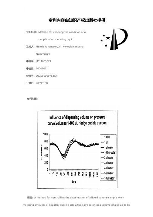
专利名称:Method for checking the condition of asample when metering liquid发明人:Henrik Johansson,Olli Myyrylainen,JuhaNummipuro申请号:US11665023申请日:20041011公开号:US20090007628A1公开日:20090108专利内容由知识产权出版社提供专利附图:摘要:A method for controlling the dispensation of a liquid volume sample whenmetering amounts of liquid by sucking into a tube, probe or tip a volume of a liquid to bedisplaced and ejecting the sample to a different vessel. According to the method the metering act is performed normally and the liquid to be metered is, displaced thereafter in a desired vessel. During the metering act and after a desired amount of liquid is sucked into the metering line, a supplementary suction step is performed wherefrom the success of the metering act can be deduced. The pressure function of the supplementary suction step is measured and this function is compared with a calibration function.申请人:Henrik Johansson,Olli Myyrylainen,Juha Nummipuro地址:Espoo FI,Helsinki FI,Espoo FI国籍:FI,FI,FI更多信息请下载全文后查看。
卡尔费修滴定法简介
Karl Fischer Volumetric Titration Theory and Practice- when you need to be sure...Table of contents Introduction (3)Chemical reactions (3)pH considerations (4)Volumetric titration (5)General remarks (5)End point determination (5)The working medium (7)Water determination using Radiometer Analytical titrators (8)Use of an oven (10)Good Laboratory Practice "GLP" (11)General remarks (11)The KF titration cell (11)Stirring speed (12)Delivery tip and indicating electrode (12)The burette (12)GLP (12)Safety (12)Result calculations (13)IntroductionWater content needs to be determined at all stages of the manufacturing process from raw materials to finished goods. The quality of the product depends on it. In products such as kerosene, transformer insulation oil or brake oil, the presence of unwanted moisture can have disastrous consequences.In the pharmaceutical industry, it is essential to know the amount of water contained in the ingredients of a drug in order to correctly predict its lifetime, stability and effectiveness.In the food industry, the water content of both raw materials and the finished foodstuff needs to be carefully monitored.The technique most commonly used for these analyses because of its rapidity,accuracy and ease of use is Karl Fischer titration.Thanks to their design and titration algorithm, Radiometer Analytical Karl Fischer Titrators provide accurate results and clear sample information. Radiometer Analytical makes it easy for the user to comply with Quality Control requirements and follow Good Laboratory Practice.The instrument is easy to program due to preset methods for titrations in the most common samples. The last calibration results of titrants, blanks and samples are stored. When used in conjunction with dedicated PC software, archiving of results and methods is limited only by available storage space.Chemical reactionsThe titration is based on the oxidation of sulphur dioxide by iodine in the presence of water. It is the same reaction as the iodometric titration of sulphur dioxide in water.I 2 + SO 2 + 2H 2O Ù2HI + H 2SO 4(I)In 1935, Karl Fischer published a description of “a new procedure for the titration of water” using the above reaction in an anhydrous nonaqueous solvent. However, in order to shift the equilibrium (I) to the right, it was necessary to neutralise the acids produced. Originally pyridine was used as the neutralising base. Later on,diethanolamine followed by imidazole were used as buffers.Recent studies show that methanol, which is the most commonly used solvent,contributes in the reaction. The Karl Fischer titration can therefore be described by the two following reactions:CH 3OH + SO 2 + RN => [RNH]SO 3CH 3(II)H 2O + I 2 + [RNH]SO 3CH 3 + RN -> [RNH]SO 4CH 3 + 2[RNH]I(III)(RN designates the base used)Ethanol-based reagents have recently emerged. These have the advantage of being less toxic, offering more stable endpoints and faster kinetics.pH considerationsThe Karl Fischer reaction can only take place in a certain pH range between 5 and7. In this pH range, the reaction remains constant. If the pH drops too low, end point attainment becomes sluggish or an end point will not be reached at all. If the pH is too high, side reactions occur making the titration non-stoichiometric. We can therefore say that errors occurring during a KF titration may be due to a change in the pH of the titration solvent.The pH of the titration solvent can be tested using a combined pH electrode and a pH meter. The electrode is first calibrated with aqueous buffer solutions and afterwards the pH of the titration solvent is measured.Note : do not place the pH electrode directly into the KF cell because excessive moisture will be introduced along with the electrode.For further information, consult the users manuals of the main manufacturers of Karl Fischer reagents.Volumetric titrationGeneral remarksVolumetric Karl Fischer titration requires the determination of the titre (t) of the Karl Fischer reagent. It is usually quoted in mg of water per ml of Karl Fischer reagent.Modern reagents allow direct titration of water in the sample. The sample may be introduced directly into the KF cell or after an extraction or dissolution with a suitable solvent. The water concentration of the solvent must be determined previously in order to be subtracted from the sample analysis.In Radiometer Analytical titrators all these operations are simplified and the different results are accounted for automatically.The volumetric titration of water allows the analysis of water concentrations between 0.1% and 100%. If an aliquot contains less than 1 mg of water, coulometric determination will result in a more accurate result. For reasons of precision, the titre of the titrant should be chosen so that the titration is completed with a titrant demand between 1 and 10 ml.End point determinationThe end point of the reaction is generally based on the detection of a slight excess of iodine which occurs when water is no longer present in the KF cell. The iodine excess can be indicated visually, photometrically or potentiometrically. The potentiometric method is the most common for the majority of titrators currently on the market.Radiometer Analytical titrators allow the use of direct or alternating current. The indicating electrode geometry and frequency of the alternating signal have been optimised. The instrument does not operate with instantaneous potential values but uses half the difference between two consecutive measurements.E = E(t) - E(t-1)2(IV)In a conventional system with dc current, the electrodes are polarised, and become the site for reactions other than the reaction iodine to iodide. This leads to a drift in the potential difference between the electrodes and an end point that may be erroneous.In figure 1, two curves for the same electrode are shown. Both have the same amplitude but one is with direct current whereas the other is with alternating current. It can be seen that with ac the potential is stabilised whereas with dc the potential increases, showing the appearance of reactions other than the reaction iodine to iodide.The amplitude of the direct or alternating current and the value of the set point are modified according to the resistivity of the reactive medium. Radiometer Analytical offer more than a simple end point titration. The instrument controls the speed of reagent addition in order to maintain the indicating electrode potential at a constant value, thus an excess of iodine is never observed. This reaction control is achieved with a self-adapting PID algorithm(1). The only input parameter is the maximum allowed speed that only depends on the reaction kinetics of the reagent used. Radiometer Analytical has tested most available reagents and the default value is valid for the most commonly used ones. The table below gives the maximum advised speed for the tested reagents.Thanks to this principle, the titrator compensates the water introduced into the KF cell by determining a drift value which is subtracted during the titration. In this way, more accurate results are obtained, especially for low water contents.(1) PID: Proportional Integral DerivativeThe working mediumThe solventThe working medium (i.e. the solvent required), can be freely chosen by the user depending on the dissolution properties of the sample to be investigated. For methanol-based reagents, the stoichiometry 1:1 of the Karl Fischer reaction is only fulfilled if there is more than 25% methanol in the reaction mixture. A methanol-free working medium can be used, however it is important to determine the titre of the KF reagent in the same working medium.The modern solvents available today present a high buffer and dissolution capacity. These solvents consist of sulphur dioxide, a base and methanol or ethanol.The main advantages of these solvents are:•A more rapid titration due to better reaction kinetics; an advantage especially for the titration of large amounts of water.•A better reproducibility, because the reaction environment is stable. The pH and the sulphur dioxide concentration remain constant.For the titration of samples producing side reactions (aldehydes, ketones and silanols), it is necessary to use an appropriate solvent. Most reagent manufacturers include the letter K in the commercial name of such solvents.Note:If you are using an ethanol-based Karl Fischer solvent (example: E-Solvent) and you have difficulties balancing your cell, you may need to immerse the Pt-Pt electrode for 2 min. in a 10% v/v T ritonX-100 solution once a week. Then rinse with dry methanol and gently wipe.This treatment allows the electrode to recover full efficiency after a few minutes operation.10% v/v TritonX-100 is available from reagent manufacturers or can be prepared by diluting 10 ml of TritonX-100 in 100 ml of deionised water.The titrantThe titrant consists of iodine dissolved in methanol or ethanol. We often find that the titrant has three titres 1, 2 and 5 mg of water per ml titrant. Even if it is possible to perform a titration with more than one stroke of the burette piston, it should be avoided by an appropriate reagent titre and choice of sample size. This allows the titration time to be reduced and therefore improves the reproducibility.The titration of samples producing side reactions (aldehydes, ketones and silanols) requires an appropriate solvent.The following table gives the recommended maximum speeds for given reagents and solvents. However, conditions may be modified with respect to the additives, solvents e.g. chloroform, or samples added.If the titrator indicates an excess of iodine at the end of the titration, the burette speed should be halved (a speed below 5 ml/min is rarely used). It should be remembered that the titration time is not necessarily proportional to the rate of reagent addition. It is recommended to adapt the addition rate so that it is proportional to the speed of the Karl Fischer chemical reaction. Increasing the speed may lead to a momentary excess of non reacted iodine which puts a stop to the reagent addition. The titrator must therefore wait until this excess has been consumed before continuing the reagent addition.Water determination using Radiometer Analytical titrators1)Filling the burette with titrantPlace the reagent bottle in the bottle holder (if mounted) and connect the suction tubing from titrant bottle to stopcock. Add desiccant to the absorption chamber mounted on the bottle. To prepare the titrant, use the titrator burette functions “Bottle exchange” or “New titrant”.Note: replace the desiccant when saturated.2)Filling the KF cell with solventPlace the solvent bottle in the bottle holder (if mounted) and connect the tubing from the solvent bottle to the KF cell. Fill the desiccant tubes for KF cell and KF pump with an appropriate desiccant, e.g. silica gel. Start the pump then using the titrator solvent button, add between 30 and 40 ml of solvent to the titration cell. Radiometer Analytical has marked the KF cell to indicate the minimum level to which solvent must be added.3)Mounting the waste bottleLabel and identify the waste bottle and place the bottle at the rear of the titrator. Connect the tubings, KF cell to waste bottle and pump to waste bottle. Make sure that the tubing is correctly connected to the pump module. A bad connection could release liquid into the pneumatic module and cause severe damage. Start the pump then use the waste button to empty the cell.4)Pre-titrationPre-titration allows the removal of traces of water introduced with the solvent. It is only necessary if the stand by function is not used.5)Sample introductionThe titrator is ready to start titrating when the message "Introduce sample" appears on the display.In general, at least 5 mg/ml is allowed. With a newly filled KF cell, it is possible to titrate 5 x 35 = 175 mg of water.6)Titrating the waterIf "Autostart" has been activated, the titration will start as soon as the water in the sample is detected. Otherwise the titration will start as soon as the ✓ key is pressed. The titrator constantly determines the speed of titrant addition which is adapted to the titration. The introduction or simple confirmation of the sample addition can be carried out by the operator in his own time. In fact, the titration may have finished before the sample amount is introduced. The titrator waits for the input of the sample amount before calculating the final result.7)Result calculationThe titrator calculates the water content of the sample. The drift measured from titration start and if necessary the quantity of water introduced by the blank, the dilution factor etc.are also taken into account during calculations.At the same time, the titrator will determine whether or not the result falls within the acceptance range specified by the user during programming. This allows the user to determine if the water content conforms to the specifications and if the result can be used for statistical purposes.8)Solvent renewalIt is possible to perform successive titrations in the same solvent. However, it is important to ensure that the methanol concentration is above 25% and that pH is maintained within the range 5 to 7.Although it is advisable to renew the solvent after each analysis, successive titrations may be performed using the same solvent. Due to the fact that the quantity of sulphur dioxide present in the cell is limited, care must be taken to respect the quantity of water that can be analysed using the volume of solvent present in the KF cell. For further information, consult the reagent manufacturer's instructions for use.9)Restarting the titration using a new aliquot or return to the start ofa menuThe KF titration cell will remain permanently on stand by i.e. ready for immediate use.10)At the end of a series of titrations, the following statisticalcalculations are performed:•Mean.•Standard deviation.Use of an ovenThe oven is necessary when:•The solvent does not allow a sufficient dissolution of the sample.•The sample interacts with the working medium.•The sample inhibits the response of the indicating electrodes.The preparation steps 1 to 4 for the titration are identical to the conventional method. Use a specific method based on the preprogrammed "Oven KF method".Remember to pre-titrate the cell after having turned on the gas flow.1.The titrator prompts you to weigh an "advised" amount of aliquot. Theapproximate value of this aliquot has been entered in the titrator beforehand.2.Introduce the sample in the oven's cold zone.3.Enter the "exact" amount of sample weighed.4.The titrator will determine the drift value.5.Move the sample to the oven's hot zone.6.The titration will start automatically if the option “Autostart” has been selected.The titrator will display the result until the end of the titration.7.Withdraw the sample from the oven.8.Start a new titration with another aliquot or return to the menu. The cell willremain in stand by condition, i.e. ready for a new titration.9.At the end of a series of titrations statistical calculations are performed.The user is guided through all the stages in the titration by the titrator's, clear and concise messages. In this way the quality of the analyses is optimised.Good Laboratory Practice"GLP"General remarksPerforming Karl Fischer titrations is more demanding than other volumetric titrations. Radiometer Analytical titrators guide the user step-by-step to ensure reliable and reproducible results are obtained every time.The main difficulties of a Karl Fischer titration are:•The omnipresence of water in the atmosphere. Leakage of water and vapour in the cell during the titration will lead to an erroneous result.Radiometer Analytical has designed a titration stand which is easy to use and ensures operation without contact with the external atmosphere. An electronically driven pump allows addition of solvent and emptying of the cell without any leakage. The user should inspect the desiccant tubes regularly and replace the desiccant when saturated.•Side reactions will be detrimental to the accuracy of the titration. For example, the reaction with iodine (ketones and aldehydes) or reactions which inhibit the response of the indicating electrodes. In the first case, a specific reagent should be used to reduce the influence of these side reactions and in the latter, an oven is required.The KF titration cellIt is recommended to always leave the cell on stand by, i.e. the titrator measures the effect of ambient humidity during conditioning so that the KF cell is ready for immediate use.The built-in electronically driven pump assures the draining of the KF cell. In this way, exchanges with ambient humidity as well as solvent handling are avoided. Start the pump then press the emptying button. When the cell is empty, release the button then stop the pump. T o add solvent, start the pump then hold the solvent button down until the solvent reaches the level marked on the cell.The KF titration cell should be completely disassembled if not being used for longer periods of time. The parts should be washed in methanol and then dried. The parts can also be dried in an oven. The temperature of the oven must not exceed 50°C. Higher temperatures are not recommended as this can lead to deformation of plastic parts.Stirring speedThe stirring speed should be selected to ensure a rapid mixing of the reagent added, without introducing an excessive amount of air into the solution. Insufficient stirring can easily lead to an over-titration whereas excessive stirring may disturb the response of the electrodes.Delivery tip and indicating electrodeThe delivery tip should be placed after the indicating electrode following the direction of rotation of the stirrer.The buretteMost manufacturers titrant and solvent bottles can be connected directly to Radiometer Analytical titrators using the bottle stoppers supplied.The burette should be equipped with an absorption chamber filled with silica gel or a molecular sieve for H 2O absorption. This will preserve the titre of the titrant and limit titrant consumption during the pre-titration of the solvent.GLPEven with all the precautions taken in order to preserve the titre of the KF reagent,it is recommended to perform a calibration at regular intervals. The titrator alerts the operator when a calibration is necessary. The calibration interval is entered by the operator during programming. In the same way, when using dedicated PC software,it is possible to enter a KF titre expiry date during programming of the KF reagent library. The operator will then be prompted when it is time to replace the KF e of dedicated PC software allows unlimited archiving of results and data and lets you consult your results and methods at all times. As many as 7 titrators can be connected via a standard RS232C serial port.SafetyA ventilation hood is advisable, particularly if a titrant containing pyridine is used.Please note that, almost all KF titrants and solvents used are inflammable and toxic.Result calculationsThe titrator automatically calculates the water content of the sample in the chosen units. The drift measured from the start of the titration, the quantity of water introduced by the solvent and the dilution parameters are also taken into account during calculations. If a series of measurements is performed, the titrator will calculate the mean value, the standard deviation and the uncertainty on the mean value.The user is able to accept or refuse the last result obtained and check the impact it might have on the mean result. A rejected result will remain in the GLP table with the indication “rejected”.Finally, the titrator includes specific QC parameter setting together with High-Low alarms to help operators make the right choice in reviewing results.P r i n t e d b y R a d i o m e t e r A n a l y t i c a l S A S • F r a n c e • 2007-01E A l l r i g h t s r e s e r v e d For United States sales and service, contact:Hach Company - P.O. Box 389 - Loveland, CO 80539Telepho ne: 800-998-8110 - Fax: 970-669-2932Radiometer Analytical is a Hach Company BrandLit. No. 4438。
E647 – 99

3.2.3cycle —in fatigue,under constant amplitude loading,the load variation from the minimum to the maximum and thento the minimum load.3.2.3.1Discussion —In spectrum loading,the definition ofcycle varies with the counting method used.3.2.3.2Discussion —In this test method,the symbol N isused to represent the number of cycles.3.2.4fatigue-crack-growth rate,da/dN,[L ]—crack exten-sion per cycle of loading.3.2.5fatigue cycle —See cycle .3.2.6load cycle —See cycle.3.2.7load range,D P [F ]—in fatigue,the algebraic differ-ence between the maximum and minimum loads in a cycle expressed as:D P 5P max 2P min(1)N OTE 1—Dimensions are in millimetres (inches).N OTE 2—A -surfaces shall be perpendicular and parallel as applicable to within 60.002W ,TIR.N OTE 3—The intersection of the tips of the machined notch (a n )with the specimen faces shall be equally distant from the top and bottom edges of the specimen to within 0.005W .N OTE 4—Surface finish,including holes,shall be 0.8(32)or better.FIG.1Standard Compact-Tension C(T)Specimen for Fatigue Crack Growth RateTestingN OTE1—Dimensions are in millimetres (inches).N OTE2—The machined notch (2a n )shall be centered to within 60.001W .N OTE3—For specimens with W >75mm (3in.)a multiple pin gripping arrangement is recommended,similar to that described in Practice 561.N OTE 4—Surface finish,including holes,shall be 0.8(32)or better.FIG.2Standard Middle-Tension M(T)Specimen for Fatigue Crack Growth Rate Testing when W #75mm (3in.)3.2.8load ratio(also called stress ratio),R—in fatigue,the algebraic ratio of the minimum to maximum load(stress)in a cycle,that is,R5P min/P max.3.2.9maximum load,P max[F]—in fatigue,the highest algebraic value of applied load in a cycle tensile loads are considered positive and compressive loads negative.3.2.10maximum stress-intensity factor,K max[FL−3/2]—in fatigue,the maximum value of the stress-intensity factor in a cycle.This value corresponds P max.3.2.11minimum load,P min[F]—in fatigue,the lowest algebraic value of applied load in a cycle.Tensile loads are considered positive and compressive loads negative.3.2.12minimum stress-intensity factor,K min[FL−3/2]—in fatigue,the minimum value of the stress-intensity factor in a cycle.This value corresponds to P min when R>0and is taken to be zero when R#0.3.2.13stress cycle—See cycle in Terminology E616.3.2.14stress-intensity factor,K,K1,K2,K3[FL−3/2]—See Terminology E616.3.2.14.1Discussion—In this test method,mode1is as-sumed and the subscript1is everywhere implied.3.2.15stress-intensity factor range,D K[FL−3/2]—in fa-tigue,the variation in the stress-intensity factor in a cycle,that isD K5K max2K min(2)3.2.15.1Discussion—The loading variables R,D K,and K max are related in accordance with the following relation-ships:D K5~12R!K max for R$0,and(3)D K5K max for R#0.3.2.15.2Discussion—These operational stress-intensity fac-tor definitions do not include local crack-tip effects;for example,crack closure,residual stress,and blunting.3.2.15.3Discussion—While the operational definition ofD K states that D K does not change for a constant value of K max when R#0,increases in fatigue crack growth rates can be observed when R becomes more negative.Excluding the compressive loads in the calculation of D K does not influence the material’s response since this response(da/dN)is indepen-dent of the operational definition of D K.For predicting crack-growth lives generated under various R conditions,the life prediction methodology must be consistent with the data reporting methodology.3.2.16stress-intensity factor range—See range of stress-intensity factor.3.3Definitions of Terms Specific to This Standard:3.3.1applied-K curve—a curve(afixed-load orfixed-displacement crack-extension-force curve)obtained from a fracture mechanics analysis for a specific specimen configura-tion.The curve relates the stress-intensity factor to crack size and either applied load or displacement.3.3.1.1Discussion—The resulting analytical expression is sometimes called a K calibration and is frequently available in handbooks for stress-intensity factors.3.3.2fatigue crack growth threshold,D K th[FL−3/2]—that asymptotic value of D K at which d a/d N approaches zero.For most materials an operational,though arbitrary,definition of D K th is given as that D K which corresponds to a fatigue crack growth rate of10−10m/cycle.The procedure for determining this operational D K th is given in9.4.3.3.2.1Discussion—The intent of this definition is not to define a true threshold,but rather to provide a practical means of characterizing a material’s fatigue crack growth resistance in the near-threshold regime.Caution is required in extending this concept to design(see5.1.5).3.3.3fatigue crack growth rate,da/d N or D a/D N,[L]—in fatigue,the rate of crack extension caused by fatigue loading and expressed in terms of average crack extension per cycle.3.3.4K-decreasing test—a test in which the value of C is nominally negative.In this test method K-decreasing tests are conducted by shedding load,either continuously or by a series of decremental steps,as the crack grows.3.3.5K-increasing test—a test in which the value of C is nominally positive.For the standard specimens in this method the constant-load-amplitude test will result in a K-increasing test where the C value increases but is always positive.3.3.6normalized K-gradient,C5(1/K).d K/d a[L−1]—the fractional rate of change of K with increasing crack length.3.3.6.1Discussion—When C is held constant the percent-age change in K is constant for equal increments of crack length.The following identity is true for the normalized K-gradient in a constant load ratio test:1K·d Kd a51K max·dK maxd a51K min·d K mind a51D K·d D Kd a(4)4.Summary of Test Method4.1This test method involves cyclic loading of notched specimens which have been acceptably precracked in fatigue. Crack length is measured,either visually or by an equivalent method5,as a function of elapsed fatigue cycles and these data are subjected to numerical analysis to establish the rate of crack growth.Crack growth rates are expressed as a function of the stress-intensity factor range,D K,which is calculated from expressions based on linear elastic stress analysis.5.Significance and Use5.1Fatigue crack growth rate expressed as a function of crack-tip stress-intensity factor range,d a/d N versus D K,char-acterizes a material’s resistance to stable crack extension under cyclic loading.Background information on the ration-ale for employing linear elastic fracture mechanics to analyze fatigue crack growth rate data is given in Refs(1)6and(2).5.1.1In innocuous(inert)environments fatigue crack growth rates are primarily a function of D K and load ratio,R, or K max and R(Note1).Temperature and aggressive environ-ments can significantly affect d a/d N versus D K,and in many cases accentuate R-effects and introduce effects of other loading variables such as cycle frequency and waveform.5Subcommittee E08.06has initiated a task group activity(E08.06.06)on nonvisual methods for measuring crack growth.These measurement methods include compliance(near front face and back face),a-c potential,d-c potential,eddy current,ultrasonic,and acoustic emission.Refs(1)and(3)provide basic informa-tion on the current uses of these methods.6The boldface numbers in parentheses refer to the list of references at the end of thisstandard.Attention needs to be given to the proper selection and control of these variables in research studies and in the generation of design data.N OTE 1—D K ,K max ,and R are not independent of each other.Specifi-cation of any two of these variables is sufficient to define the loading condition.It is customary to specify one of the stress-intensity parameters (D K or K max )along with the load ratio,R .5.1.2Expressing d a /d N as a function of D K provides results that are independent of planar geometry,thus enabling ex-change and comparison of data obtained from a variety of specimen configurations and loading conditions.Moreover,this feature enables d a /d N versus D K data to be utilized in the design and evaluation of engineering structures.The concept of similitude is assumed,which implies that cracks of differing lengths subjected to the same nominal D K will advance by equal increments of crack extension per cycle.5.1.3Fatigue crack growth rate data are not always geometry-independent in the strict sense since thickness effects sometimes occur.However,data on the influence of thickness on fatigue crack growth rate are mixed.Fatigue crack growth rates over a wide range of D K have been reported to either increase,decrease,or remain unaffected as specimen thickness is increased.Thickness effects can also interact with other variables such as environment and heat treatment.For ex-ample,materials may exhibit thickness effects over the termi-nal range of d a/d N versus D K ,which are associated with either nominal yielding (Note 2)or as Kmax approaches the materialfracture toughness.The potential influence of specimen thick-ness should be considered when generating data for research or design.N OTE 2—This condition should be avoided in tests that conform to the specimen size requirements of 7.2.5.1.4Residual stresses can have an influence on fatigue crack growth rate behavior.The effect can be significant when test specimens are removed from material in which complete stress relief is impractical,such as weldments,as-quenched materials,and complex forged or extruded shapes.Residual stresses superimposed on the applied stress can cause the localized crack-tip stress-intensity factor to be different than that computed solely from externally applied loads.Residual stresses may lead to partly compressive stress cycles,even when the nominal applied stress range is wholly tensile,or vice versa.Irregular crack growth,namely excessive crack front curvature or out-of-plane crack growth,generally indicates that residual stresses are affecting the measured d a /d N versus D K relationship (4).5.1.5The growth rate of small fatigue cracks can differ noticeably from that of long cracks at given D K e of long crack data to analyze small crack growth often results in non-conservative life estimates.The small crack effect may be accentuated by environmental factors.Cracks are defined as being small when 1)their length is small compared to relevant microstructural dimension (a continuum mechanics limitation),2)their length is small compared to the scale of local plasticity (a linear elastic fracture mechanics limitation),and 3)they are merely physically small (<1mm).Near-threshold data estab-lished according to this method should be considered as representing the materials’steady-state fatigue crack growth rate response emanating from a long crack,one that is of sufficient length such that transition from the initiation to propagation stage of fatigue is complete.Steady-state near-threshold data,when applied to service load histories,may result in non-conservative lifetime estimates,particulary for small cracks (5-7).75.1.6Crack closure can have a dominant influence on fatigue crack growth rate behavior,particularly in the near-threshold regime at low stress ratios.This implies that the conditions in the wake of the crack and prior loading history can have a bearing on the current propagation rates.The understanding of the role of the closure process is essential to such phenomena as the behavior of small cracks and the transient crack growth rate behavior during variable amplitude loading.Closure provides a mechanism whereby the cyclic stress intensity near the crack tip,D K eff ,differs from the nominally applied values,D K .This concept is of importance to the fracture mechanics interpretation of fatigue crack growth rate data since it implies a non-unique growth rate dependence in terms of D K ,and R (8).8N OTE 3—The characterization of small crack behavior may be more closely approximated in the near-threshold regime by testing at a high stress ratio where the anomalies due to crack closure are minimized.5.2This test method can serve the following purposes:5.2.1To establish the influence of fatigue crack growth on the life of components subjected to cyclic loading,provided data are generated under representative conditions and com-bined with appropriate fracture toughness data (for example,see Test Method E 399),defect characterization data,and stress analysis information (9,10).N OTE 4—Fatigue crack growth can be significantly influenced by load history.During variable amplitude loading,crack growth rates can be either enhanced or retarded (relative to steady-state,constant-amplitude growth rates at a given D K )depending on the specific loading sequence.This complicating factor needs to be considered in using constant-amplitude growth rate data to analyze variable amplitude fatigue problems (11).5.2.2To establish material selection criteria and inspection requirements for damage tolerant applications.5.2.3To establish,in quantitative terms,the individual and combined effects of metallurgical,fabrication,environmental,and loading variables on fatigue crack growth.6.Apparatus 6.1Grips and Fixtures for C(T)Specimens —A clevis and pin assembly (Fig.3)is used at both the top and bottom of the specimen to allow in-plane rotation as the specimen is loaded.This specimen and loading arrangement is to be used for tension-tension loading only.6.1.1Suggested proportions and critical tolerances of the clevis and pin are given (Fig.3)in terms of either the specimen width,W ,or the specimen thickness,B ,since these dimensions may be varied independently within certain limits.6.1.2The pin-to-hole clearances illustrated in Fig.3are designed to reduce nonlinear load vs.displacement behavior 7Subcommittee E08.06has initiated a study group activity on crack closure measurement and analysis.Reference (8)provides basic information on this subject.8Supporting data available from ASTM Headquarters.Request RR:E-24-1009.caused by rotation of the specimen and pin (12).Using this arrangement to test materials with relatively low yield strength may cause plastic deformation of the specimen hole.Similarly,when testing high strength materials or when the clevis opening exceeds 1.05B (or both),a stiffer load pin (that is,>0.225W )may be required.In these cases,a flat bottom clevis hole or bearings may be used with the appropriate loading pins (D 50.24W )as indicated in Annex A2.The use of high viscosity lubricants such as grease may introduce hysteresis in the load vs.displacement behavior and is not recommended.6.1.3Using a 1000-MPa (150-ksi)yield-strength alloy (for example,AISI 4340steel)for the clevis and pins provides adequate strength and resistance to galling and fatigue.6.2Grips and Fixtures for M(T)Specimens —The types of grips and fixtures to be used with the M(T)specimens will depend on the specimen width,W ,(defined in Fig.2),and the loading conditions (that is,either tension-tension or tension-compression loading).The minimum required specimen gage length varies with the type of gripping and is specified so that a uniform stress distribution is developed in the specimen gage length during testing.For testing of thin sheets,constraining plates may be necessary to minimize specimen buckling (see Practice E 561for recommendations on buckling constraints).6.2.1For tension-tension loading of specimens with W #75mm (3in.)a clevis and single pin arrangement is suitable for gripping provided that the specimen gage length (that is,the distance between loading pins)is at least 3W (Fig.2).For this arrangement it is also helpful to either use brass shims between the pin and specimen or to lubricate the pin to prevent fretting-fatigue cracks from initiating at the specimen loading hole.Additional measures which may be taken to prevent cracking at the pinhole include attaching reinforcement plates to the specimen (for example,see Test Method E 338)or employing a “dog bone”type specimen design.In either case,the gage length shall be defined as the uniform section and shall be at least 1.7W .6.2.2For tension-tension loading of specimens with W $75mm (3in.)a clevis with multiple bolts is recommended (for example,see Practice E 561).In this arrangement,the loads are applied more uniformly;thus,the minimum specimen gage length (that is,the distance between the innermost row of bolt holes)is relaxed to 1.5W .6.2.3The M(T)specimen may also be gripped using a clamping device instead of the above arrangements.This type of gripping is necessary for tension-compression loading.An example of a specific bolt and keyway design for clamping M(T)specimens is given in Fig. 4.In addition,various hydraulic and mechanical-wedge systems which supply ad-equate clamping force are commercially available and may be used.The minimum gage length requirement for clamped specimens is relaxed to 1.2W .6.3Alignment of Grips —It is important that attention be given to achieving good alignment in the load train through careful machining of all gripping fixtures.Misalignment can cause non-symmetric cracking,particularly for critical appli-cations such as near-threshold testing,which in turn may lead to invalid data (see Sec.8.3.4,8.8.3).If non-symmetric cracking occurs,the use of a strain-gaged specimen to identify and minimize misalignment might prove useful.One method to identify bending under tensile loading conditions is described in Practice E 1012.Another method which specifically ad-dresses measurement of bending in pin-loaded specimen con-figurations is described in Ref (13).For tension-compression loading the length of the load train (including thehydraulic N OTE 1—Dimensions are in millimetres (inches).N OTE 2—A -surfaces shall be perpendicular and parallel as applicable to within 60.05mm (0.002in.),TIR.N OTE 3—Surface finish of holes and loading pins shall be 0.8(32)or better.FIG.3Clevis and Pin Assembly for Gripping C(T)Specimens FIG.4Example of Bolt and Keyway Assembly for Gripping100-mm (4-in.)wide M(T)Specimenactuator)should be minimized,and rigid,non-rotating joints should be employed to reduce lateral motion in the load train.7.Specimen Configuration,Size,and Preparation7.1Standard Specimens —The geometry of standard C(T)and M(T)specimens is given in Figs.1and 2,respectively.The geometry of the standard ESE(T)specimen is given in Fig.A4.1.The specific geometry of M(T)specimens depends on the method of gripping as specified in 6.2.Notch and precrack-ing details for the specimens are given in Fig.5.The C(T)and ESE(T)specimen are not recommended for tension-compression testing because of uncertainties introduced into the loading experienced at the crack tip.N OTE 5—In the near threshold regime (below 10−8m/cycle),one can experience difficulty in meeting the crack symmetry requirements of 8.8.3when using the M(T)specimen;the C(T)or ESE(T)specimen may be an appropriate alternative.7.1.1It is required that the machined notch,an ,in the C(T)specimen be at least 0.2W in length so that the K -calibration is not influenced by small variations in the location and dimen-sions of the loading-pin holes.7.1.2The machined notch,2an ,in the M(T)specimen shallbe centered with respect to the specimen centerline to within60.001W .The length of the machined notch in the M(T)specimen will be determined by practical machining consider-ations and is not restricted by limitations in the K -calibration.N OTE 6—It is recommended that 2a n be at least 0.2W when using the compliance method to monitor crack extension in the M(T)specimen so that accurate crack length determinations can be obtained.7.1.3For the specimens described in this method,the thickness,B ,and width,W ,may be varied independently within the following limits,which are based on specimen buckling and through-thickness crack-curvature consider-ations:7.1.3.1For C(T)and ESE(T)specimens it is recommended that thickness be within the range W /20#B #W /4.Specimens having thicknesses up to and including W /2may also be employed;however,data from these specimens will often require through-thickness crack curvature corrections (see 9.1).In addition,difficulties may be encountered in meeting the through-thickness crack straightness requirements of 8.3.4and 8.8.3.7.1.3.2Using the above rationale,the recommended upper limit on thickness in M(T)specimens is W /8,although W /4may also be employed.The minimum thickness necessary to avoid excessive lateral deflections or buckling in M(T)speci-mens is sensitive to specimen gage length,grip alignment,and load ratio,R .It is recommended that strain gage information be obtained for the particular specimen geometry and loading condition of interest and that bending strains not exceed 5%of the nominal strain.7.1.3.3For specimens removed from material for which complete stress relief is impractical (see 5.1.4),the effect of residual stresses on the crack propagation behavior can be minimized through the careful selection of specimen shape and size.By selecting a small ratio of specimen dimensions,b/w the effect of a through-the-thickness distribution of residual stresses acting perpendicular to the direction of crack growth can be reduced.This choice of specimen shape minimizes crack curvature or other crack front irregularities which con-fuse the calculation of both d a /d N and D K .Residual stresses acting parallel to the direction of crack growth can produce moments about the cracktip which also confound test results.These residual stresses can be minimized by selecting sym-metrical specimen configurations,that is,the M(T)specimen,for the evaluation of the material’s crack growth behavior.7.2Specimen Size —In order for results to be valid accord-ing to this test method it is required that the specimen be predominantly elastic at all values of applied load.The minimum in-plane specimen sizes to meet this requirement are based primarily on empirical results and are specific to specimen configuration (10).7.2.1For the C(T)and ESE(T)specimen the following is required:~W 2a !$~4/p !~K max /s YS !2(5)where:(W −a)5specimen’s uncracked ligament (Fig.1),and s YS 50.2%offset yield strength determined at the same temperature as used when measuring the fatigue crack growth rate data.7.2.2For the M(T)specimen the following is required:~W 22a !$1.25P max /~B s YS !(6)where:FIG.5Notch Details and Minimum Fatigue PrecrackingRequirements(W−2a)5specimen’s uncracked ligament(Fig.2),and B5specimen thickness.N OTE7—The size requirements in7.2are appropriate for low-strainhardening materials(sULT /sYS#1.3)(14)and for high-strain hardeningmaterials(sULT /sYS$1.3)under certain conditions of load ratio andtemperature(15,16)(where sULT is the ultimate tensile strength of thematerial).However,under other conditions of load ratio and temperature, these same requirements appear to be overly restrictive—that is,they require specimen sizes which are larger than necessary(17,18).Currently, the conditions giving rise to each of these two regimes of behavior are not clearly defined.7.2.2.1An alternative size requirement may be employed for high-strain hardening materials as follows.The uncracked ligament requirement may be relaxed by replacing s YS with a higher,effective yield strength which accounts for the material strain hardening capacity.For purposes of this test method,this effective yield strength,termedflow strength,is defined as follows:s FS5~s YS1s ULT!/2(7) However,it should be noted that the use of this alternative size requirement allows mean plastic deflections to occur in the specimen.These mean deflections under certain conditions,as noted previously,can accelerate growth rates by as much as a factor of two.Although these data will generally add conser-vatism to design or structural reliability computations,they can also confound the effects of primary variables such as speci-men thickness(if B/W is maintained constant),load ratio,and possibly environmental effects.Thus,when the alternative size requirement is utilized,it is important to clearly distinguish between data that meet the yield strength orflow strength criteria.In this way,data will be generated that can be used to formulate a specimen size requirement of general utility.7.3Notch Preparation—The machined notch for either of the standard specimens may be made by electrical-discharge machining(EDM),milling,broaching,or sawcutting.The following notch preparation procedures are suggested to facili-tate fatigue precracking in various materials:7.3.1Electric Discharge Machining—r<0.25mm(0.010 in.)(r5notch root radius),high-strength steels(s YS$1175 MPa/170ksi),titanium and aluminum alloys.7.3.2Mill or Broach—r#0.075mm(0.003in.),low or medium-strength steels(s YS#1175MPa/170ksi),aluminum alloys.7.3.3Grind—r#0.25mm(0.010in.),low or medium-strength steels.7.3.4Mill or Broach—r#0.25mm(0.010in.),aluminum alloys.7.3.5Sawcut—Recommended only for aluminum alloys.7.3.6Examples of various machined-notch geometries and associated precracking requirements are given in Fig.5(see 8.3).7.3.7When residual stresses are suspected of being present (see5.1.4),local displacement measurements made before and after machining the crack starter slot are useful for detecting the potential magnitude of the effect.A simple mechanical displacement gage can be used to measure distance between two hardness indentations at the mouth of the notch(4). Limited data show that for aluminum alloys when these mechanical displacement measurements change by more than 0.05mm(0.002in.),fatigue crack growth rates can be changed significantly.8.Procedure8.1Number of Tests—At crack growth rates greater than 10−8m/cycle,the within-lot variability(neighboring speci-mens)of d a/d N at a given D K typically can cover about a factor of two(19).At rates below10−8m/cycle,the variability in d a/d N may increase to about a factor offive or more due to increased sensitivity of d a/d N to small variations in D K.This scatter may be increased further by variables such as micro-structural differences,residual stresses,changes in crack tip geometry(crack branching)or near tip stresses as influenced for example by crack roughness or product wedging,load precision,environmental control,and data processing tech-niques.These variables can take on added significance in the low crack growth rate regime(d a/d N<10−8m/cycle).In view of the operational definition of the threshold stress-intensity (see3.3.2and9.4),at or near threshold it is more meaningful to express variability in terms of D K rather than d a/d N.It is good practice to conduct replicate tests;when this is imprac-tical,multiple tests should be planned such that regions of overlapping d a/d N versus D K data are obtained,particularly under both K-increasing and K-decreasing conditions.Since confidence in inferences drawn from the data increases with number of tests,the desired number of tests will depend on the end use of the data.8.2Specimen Measurements—The specimen dimensions shall be within the tolerances given in Figs.1and2.8.3Fatigue Precracking—The importance of precracking is to provide a sharpened fatigue crack of adequate size and straightness(also symmetry for the M(T)specimen)which ensures that1)the effect of the machined starter notch is removed from the specimen K-calibration,and2)the effects on subsequent crack growth rate data caused by changing crack front shape or precrack load history are eliminated.8.3.1Conduct fatigue precracking with the specimen fully heat treated to the condition in which it is to be tested.The precracking equipment shall be such that the load distribution is symmetrical with respect to the machined notch and K max-during precracking is controlled to within65%.Any conve-nient loading frequency that enables the required load accuracy to be achieved can be used for precracking.The machined notch plus the precrack must lie within the envelope,shown in Fig.5,that has as its apex the end of the fatigue precrack.In addition the fatigue precrack shall not be less than0.10B,h,or 1.0mm(0.040in.),whichever is greater(Fig.5).8.3.2Thefinal K max during precracking shall not exceed the initial K max for which test data are to be obtained.If necessary, loads corresponding to higher K max values may be used to initiate cracking at the machined notch.In this event,the load range shall be stepped-down to meet the above requirement. Furthermore,it is suggested that reduction in P max for any of these steps be no greater than20%and that measurable crack extension occur before proceeding to the next step.To avert transient effects in the test data,apply the load range in each step over a crack length increment of at least(3/p)(K8max/ s YS)2,where K8max is the terminal value of K max fromthe。
板材防火检验报告
板材防火检验报告1. 引言本报告旨在对板材的防火性能进行评估和检验。
防火检验是确保板材符合相关防火标准和法规的重要步骤,以保障公共安全和防止火灾事故的发生。
本报告详细介绍了防火检验的方法、结果和结论。
2. 检验方法本次防火检验采用了国际标准组织(ISO)制定的防火测试方法,具体采用了以下测试:2.1. 构建材料分类根据板材的用途和特性,将其归类于适当的构建材料分类中。
2.2. 反应对加热的测试(ASTM E1354)该测试方法通过对板材的燃烧过程进行定量测量来评估其防火性能。
在测试过程中,板材样本暴露在控制条件下的加热源下,通过测量其温度和排放物质量来评估其燃烧特性。
2.3. 热释放量测试(ASTM E1354)该测试方法通过测量板材样本燃烧产生的热释放量来评估其防火性能。
测试过程中,板材样本放置在燃烧室中,通过测量燃烧过程中释放的热量来评估其燃烧特性。
2.4. 火焰蔓延测试(ASTM E84)该测试方法通过测量板材样本的火焰蔓延速度来评估其防火性能。
测试过程中,板材样本在水平设备上进行燃烧,通过观察火焰蔓延的速度和燃烧后的残留物来评估其燃烧特性。
3. 检验结果根据上述的防火测试方法,我们对板材样本进行了全面的检验,并得出以下结果:•反应对加热的测试结果显示,板材样本在加热的过程中,温度变化较小,没有明显的燃烧迹象,符合防火要求。
•热释放量测试结果显示,板材样本在燃烧过程中,热释放量较低,表明具有较好的防火性能。
•火焰蔓延测试结果显示,板材样本的火焰蔓延速度较慢,且燃烧后的残留物较少,符合防火要求。
综上所述,板材样本通过了我们的防火检验,具备较好的防火性能,可以安全使用在相关的建筑和装饰领域。
4. 结论根据本次板材防火检验的结果,我们得出以下结论:•板材样本在反应对加热的测试中未出现明显的燃烧迹象,符合防火要求。
•板材样本的热释放量较低,表明具有良好的防火性能。
•板材样本的火焰蔓延速度较慢,且燃烧后的残留物较少,符合防火要求。
- 1、下载文档前请自行甄别文档内容的完整性,平台不提供额外的编辑、内容补充、找答案等附加服务。
- 2、"仅部分预览"的文档,不可在线预览部分如存在完整性等问题,可反馈申请退款(可完整预览的文档不适用该条件!)。
- 3、如文档侵犯您的权益,请联系客服反馈,我们会尽快为您处理(人工客服工作时间:9:00-18:30)。
2010’ International Symposium on Flame-Retardant Materials & T echnologies, Sichuan University, Chengdu, China, Sept.17-20, 2010Method of Cone Calorimeter Used for Estimation of the Visibility Range in Smoke Generated during Combustion of the Epoxy MaterialsMarzena Półka *The Main School of Fire Service, Slowackiego 52/54, Warsaw 01-629, PolandKeywords: flame retardant; cone calorimeter; visibility; epoxy materialsThis work presents changes of visibility reduction rate in a smoke generated during thermal decomposition and combustion of the selected epoxy materials (with flame retardant) for a model set (room - hall). The input data used for calculation of the visibility range were the parameters describing smoke-generation capability and combustion rate defined by the mass loss rate, determined for the heat conditions occurring in the first phase of a fire [1] at the heat exposure equal to 30 and 50 kW/m 2. Flame retarding modification of the Epidian 5 resin (Ep 5) was performed at the Warsaw University of Technology at the Faculty of Material Engineering under supervision of the author of the present work.Flammability modification took place after introduction of the flame retardant: Exolit RP 6580 and Nanomer I. 28 E to liquid Ep 5.IntroductionLimited visibility makes evacuation of fire victims difficult or even impossible. Reduction of visibility caused by smoke is often the first threat for people in case of fire – before thermal impact. The investigations included smoke-generation properties depending on a type of combustion [2], oxygen concentration [3, 4], temperature of thermal decomposition, constitution and chemical structure of a material and increased pressure. Differences in the measurement conditions (particularly related to the varying heat exposure) were not taken into account what causes that there are still not many scientific publications covering smoke-generation parameters in a complementary way.The tests were performed using unmodified epoxy materials (UEp 5, thermosetting, resins from bisphenol A) and the same materials modified with flame retardants at heat exposures stated above. Assuming single-zone model of filling with smoke and conditions of maximum level of danger, the visibility range in time for the model set (room - hall) was determined.To calculate visibility range in the test room the values of SEA av obtained from examined (according to ISO5660) unmodified and modified UEp 5 and the values of mass loss in time were placed and obtaining following equation (1):()()av p C V Z t SEA m m t ⋅=⎡⎤⋅−⎣⎦(1) where C means constant describing lighting of an object (own light or reflected light): C = 8.0 and C = 3.0, respectively, according to PN-EN 60695-6-1.*Corresponding Author: E-mail: mpolka@.pl 252The present work assumes values of the critical times equal to 3 and 10 meters and does not take into account substances irritating to eyes which can reduce the visibility by 50 % to 95 %.Results & ConclusionComplete list including critical times of visibility reduction for smoke produced during combustion of UEp 5 and UEp 5 containing flame retardants in the analyzed room - hall (176 m3) arrangement that make safe evacuation possible is presented in Table 1.Table 1. Critical times of visibility reduction for smoke produced during combustionof the materials produced from UEp 5.Critical times of visibility reduction [s]C = 8.0 a C = 3.0 bExamined materialZ cr = 3 m c Z cr = 10 m c Z cr = 3 m c Z cr = 10 m cExternal heat flux with density equal to 30 kW/m2 UEp 5 114 100 106 34UEp 5 + 3% Exolit 98 76 78 8UEp 5 + 6% Exolit 89 82 83 37UEp 5 + 3% Nanomer 76 59 70 10UEp 5 + 5% Nanomer 110 103 106 64UEp 5 + 3% Nanomer and 3% Exolit 107 90 93 34UEp 5 + 3% Nanomer and 6% Exolit 100 73 75 8External heat flux with density equal to 50 kW/m25 54 45 51 14UEpUEp 5 + 3% Exolit 40 26 27 5UEp 5 + 6% Exolit 37 24 26 18UEp 5 + 3% Nanomer 48 40 42 34UEp 5 + 5% Nanomer 59 43 52 8UEp 5 + 3% Nanomer and 3% Exolit 34 16 16 13UEp 5 + 3% Nanomer and 6% Exolit 48 36 38 5Note: a represents the light source constant;b represents the reflected light constant;c represents the critical visibility range.Increasing heat exposure from 30 to 50 kW/m2 clearly reduces critical times of the visibility reduction. It means that in such conditions evacuation of known buildings equipped with evacuation symbols that are light sources is the most advantageous in terms of the range of visibility.It can be stated, that addition of Exolit (6 % in weight) at 30 kW/m2 reduces critical time of visibility range reduction more than unmodified material or the material modified with Nanomer. Basing on the obtained results, it can be stated that in the first phase of fire Nanomer introduced separately (5 % in weight) suppresses the smoke better and if the value of external heat flux increases to 50 kW/m2 the relation is maintained and additionally, better visibility is observed for UEp 5 + 3% Nanomer and for mixed modifications with higher amount of Exolit (but only for C = 3.0 and Z cr = 3 m).Start time of the beginning of thermal decomposition and combustion is influenced by density of a253heat flux – the higher the faster the process is. Chemical constitution of a material affects initial moment of thermal decomposition. Adding flame retardants significantly affects smoke release rate of Ep 5. Nanomer introduced to the UEp 5 retarded the processes of thermal decomposition and combustion and, in certain conditions, did not reduce visibility range in the analyzed room-hall arrangement.Model calculations for the arrangement with volume equal to 176.2 m3 indicate low values of critical time of visibility reduction in the room where the epoxy materials produced from Epidian 5 could be burning, especially at heat flux equal to 50 kW/m2. Critical ranges of visibility (3 and 10 m) are achieved 20 - 50 % quicker in the arrangement in case of using e.g. evacuation symbols that only reflect light (C = 3.0 instead of C = 8.0).References(1)Ignition Handbook: Principles and Application to Fire Safety Engineering Fire Investigation, RiskManagement and Forensic Science, 2001, pp 67.(2)Guidelines for Chemical Process Quantitative Risk Analysis. American Institute of Chemical Engineering:Now York, 1989, pp 45.(3)Rasbash, P. J.; Drysdale, D. D. Fire Saf. J.1982, 5, 77-80.(4)Smoke Production and Properties - SFPE Handbook of Fire Protection Engineering. NFPA: USA, 1988. 254。