OPT-1250A2F1RBH中文资料
OPT-1250
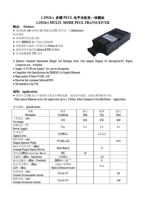
1.25Gb/s 多模 PECL 电平光收发一体模块1.25Gb/s MULTIMODE PECL TRANSCEIVER特点: Features● 采用标准 1x9封装双 SC 插拔式或 FC 尾纤式,与Multisource协议兼容● 单+3.3V供电;低功耗● 符合 IEEE802.3z 千兆以太网标准● 发射器件可选用工作波长为 850nm激光器● 接收采用平面结构 InGaAsP PIN 探测器● 信号检测逻辑 TTL电平● Industry Standard Mezzanine Height 1x9 Package Style with integral Duplex SC Receptacle/FC Pigtail Connector are available● Single+3.3V Power Supply* low power dissipation● Compliant with Specification for IEEE802.3z Gigabit Ethernet● High quality 850nm VCSELLD● Receiver has a planner InGaAsP PIN● SD interface with TTL应用:Applications● 适用于 1.25G及以下速率的千兆以太网收发器,高速光纤通道,高速交换背板等应用Fiber optical Ethernet Acess for signal rates up to 1.25Gbps ;Fiber Channel;Switch Backbone Application技术指标:Specifications参数 Parameter条件Condition最小Min典型Typ最大Max工作波长(nm)Wavelength850 830 850 860 电源电压(V)Power SupplyVcc 3.1 3.3 3.5 信号电平Signal LevelLVPECL 1.5~2.3输出谱宽(nm)Output Spectral WidthVCSELLD 0.85 输出平均光功率(dBm)Average Output Optical PowerShort Reach 8消光比(dB)Extinction Ratio EX 10灵敏度(dBm)Sensitivity 1.25Gb/s 18最小过载点(dBm)Overload BER=1×10 -10 0收无光告警点(dBm) LOS(dBm)光减小/光增加Optical Deassert/assert5/1发送电流(mA)Current of transmitter sectionVcc=3.3V 80 接收电流(mA)Current of receiver sectionVcc=3.3V 100极限值 Absolute Maximum Ratings 工作温度(℃)Operating temperature(℃) -20~+70引线焊接温度(℃)Lead soldering temperature(℃) <260 储存温度(℃)Storage temperature(℃) -40~+85引线焊接时间(Sec)Soldering duration(Sec)<10管脚定义 Pin Connections 管脚 管脚名称 电 平说 明1 GNDR 接收部分接地脚 Receiver section grounded2 RD LVPECL 接收部分数据输出Date output of receiver section3 NRD LVPECL 接收部分反向数据输出Reverse date output of receiver section 4 SD LVTTL 接收部分无光告警。
1250双机命名规范及配置

1250双机命名规范及配置1.硬件和软件配置1)ALPHA1和ALPHA2型号:HP AlphaServer DS25 68-1000主要硬件参数:(*表示数量)●CPU: HP DS25 68/1000 *2●内存: DS25 1G MEMORY OPTION *4●硬盘: 72GB 10K U320 SCSI *1●显卡: ATI 7500 PCI graphics *1●网卡: PCI to Dual 1G UTP Enet *1●网卡: PCI to Dual 100M UTP Enet *3●HBA卡: FCA2684 PCI-X,133MHz,2GB *2●冗余电源: DS25 500W Power Cord *3系统软件:●HP OPENVMS 8.2●VMS CLUSTER●FORTRAN,C,C++编译器●ORACLE数据库●APACHE+PHP●TCP/IP, RTNET通讯2)Smart Array型号:Modular SAN Array 1000 (MSA1000)主要硬件参数:●控制器: HP MSA1000 Controller 512 Cache ALL *1●交换机: MSA SAN Switch 2/8 *2●支持RAID1●7块72GB SCSI 硬盘,U320 10K●机架: *1●切换器:(共用一套鼠标键盘显示器) *1●磁盘架: *1●上架套件: *12.ALPHA机:●两台机器的节点名分别为:MASIC1(主机);MASIC2(从机);●两台机器的TCP/IP网络配置:使用独立网卡靠左边的网口,设备名称为EIB0;IP:192.168.2.184; INTERFACE: IE1; HOST:MASIC1;IP:192.168.2.186; INTERFACE: IE1; HOST: MASIC2;●心跳线的配置:使用ALPHA机的千兆网卡,设备名为EIA0:该连接只是作为直连侦测冗余使用,也可以不用配置;管理员用户:管理员用户:SYSTEM; 密码:00000000; 请不要随意改动;3.VMS系统:●用户:用户名:BKMASIC;UIC= [277,100];登陆路径: $1$DGA1:[000000.BKMASIC.ONLINE_COMMANDS]权限: /flags=nodisuser /noexp /nopwdexp /defpriv=all /priv=all注:该用户为本公司L2调试人员专用,拥有所有权限,交付客户时该用户只能提供给相关的主管人员;个人用户请自己添加;●登陆逻辑名及符号:$1$DGA1:[000000.BKMASIC.ONLINE_COMMANDS]中,需添加:$SET TERM/DEV=VT300$EDIT :== “EDIT/EDT”$ UP=="SET DEF [-]"$ DO*WN=="@$1$DGA1:[000000.BKMASIC.ONLINE_COMMANDS]"$ PURGE=PURGE/KEEP=2$@$1$DGA1:[000000.BKMASIC.ONLINE_COMMANDS]$@$1$DGA1:[000000.BKMASIC.ONLINE_COMMANDS]如果需要在系统启动时配置的逻辑名,请在:SYS$COMMON:[SYSMGR] 中配置;其他逻辑名请在SYMBOLS和LOGICALS中配置;●C,FORTRAN编译器:为确保C和FORTRAN公共区对齐,编译时需要添加对齐选项,请配置如下逻辑名:$CC:==CC/INCLUDE_DIRE=XTDLHOT_BOOT:[DEF]/FLOAT=IEEE_FLOAT -/EXTERN=COMMON /SHARE/PREFIX=ALL_ENTRIES/NOLIS/DEFINE=_VMS$FORT:==FORTRAN/ALI/CHECK/NOLIST/FLOAT=IEEE_FLOAT/EXT/CONT=99如果数据库使用时CC选项需要修改,请自行配置逻辑名;●个人用户及文件夹:个人文件夹: $1$DGA1:[000000.OTHERS…] 请在此文件夹下建立各自需要的路径;调试程序文件夹: $1$DGA1:[000000.TEST…] 请在此文件夹下建立各调试程序的路径;备份文件夹: $1$DGA1:[000000.BACKUP…]请在此文件夹下建立各备份文件的路径;4.数据库:●安装路径:$1$DGA1:[000000.ORACLE]●ORACLE DBA帐户: (VMS下配置)用户名: ORACLE10 UIC=[277,100]登陆路径: $1$DGA1:[000000.ORACLE]其他配置请参照数据库安装文档;●ORACLE登陆用户:用户名: SYS 密码:BKMASIC用户名: SYSTEM 密码:BKMASIC用户名: SCOTT 密码:TIGER用户名: BKMASIC 密码:BKMASIC其他用户请自行配置;●DATABASE配置:名称:BKMASIC SID :MASIC1名称:BKMASIC2 SID :MASIC2 APACHE以及PHP配置:PDI,HDP画面用户名:用户名:pdi 密码:pdi其他用户根据厂里要求配置;。
1250详细技术参数A
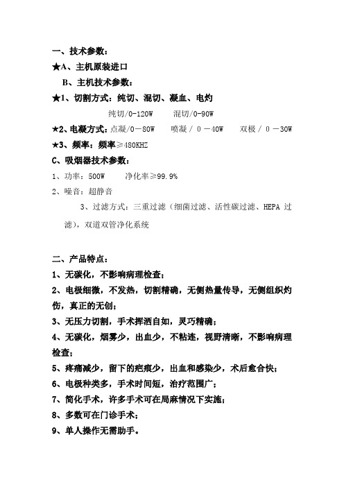
一、技术参数:
★A、主机原装进口
B、主机技术参数:
★1、切割方式:纯切、混切、凝血、电灼
纯切/0-120W 混切/0-90W
★2、电凝方式:点凝/0-80W 喷凝/0-40W 双极/0-30W ★3、频率:频率≥480KHZ
C、吸烟器技术参数:
1、功率:500W 净化率≥99.9%
2、噪音:超静音
3、过滤方式:三重过滤(细菌过滤、活性碳过滤、HEPA过
滤),双道双管净化系统
二、产品特点:
1、无碳化,不影响病理检查;
2、电极细微,不发热,切割精确,无侧热量传导,无侧组织灼伤,真正的无创;
3、无压力切割,手术挥洒自如,灵巧精确;
4、无碳化,烟雾少,出血少,不粘连,视野清晰,不影响病理检查;
5、疼痛减少,留下的疤痕少,出血和感染少,术后愈合快;
6、电极种类多,手术时间短,治疗范围广;
7、简化手术,许多手术可在局麻情况下实施;
8、多数可在门诊手术;
9、单人操作无需助手。
三、产品结构组成:。
扫频仪PD1250A
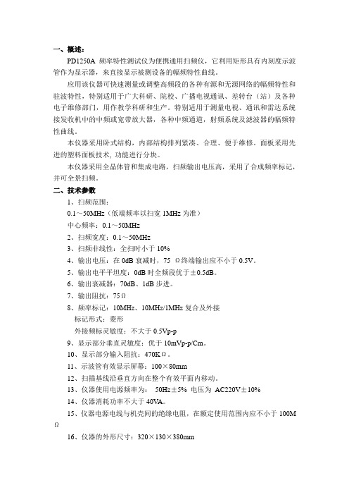
一、概述:PD1250A频率特性测试仪为便携通用扫频仪,它利用矩形具有内刻度示波管作为显示器,来直接显示被测设备的幅频特性曲线。
应用该仪器可快速测量或调整高频段的各种有源和无源网络的幅频特性和驻波特性,特别适用于广大科研、院校、广播电视通讯、差转台(站)及各种电子维修部门,用作教学科研和生产。
特别适用于测量电视、通讯和雷达系统接发收机中的中频或宽带放大器,各种中频通道,射频系统及滤波器的幅频特性曲线。
本仪器采用卧式结构,内部结构排列紧凑、合理、便于维修。
面板采用先进的塑料面板技术, 功能进行分块。
本仪器采用全晶体管和集成电路,扫频输出电压高,采用了合成频率标记,并可全景扫频。
二、技术参数1、扫频范围:0.1~50MHz(低端频率以扫宽1MHz为准)中心频率:0.1~50MHz2、扫频宽度:0.1~50MHz3、扫频非线性:全扫时小于10%4、输出电压:在0dB衰减时,75 Ω终端输出应不小于0.5V。
5、输出电平平坦度:0dB时全频段优于±0.5dB。
6、输出衰减器:70dB、1dB步进。
7、输出阻抗:75Ω8、频率标记:10MHz、10MHz/1MHz复合及外接标记形式:菱形外接频标灵敏度:不大于0.5Vp-p9、显示部分垂直灵敏度:优于10mVp-p/Cm。
10、显示部分输入阻抗:470KΩ。
11、示波管有效显示屏幕:100×80mm12、扫描基线沿垂直方向在整个有效平面内移动。
13、仪器使用电源频率为:50Hz±5% 电压为AC220V±10%14、仪器消耗功率不大于40V A。
15、仪器电源电线与机壳间的绝缘电阻,在额定使用范围内应不小于100M Ω16、仪器的外形尺寸:320×130×380mm三、工作原理:1、电源部分由变压器次级取出的各路电压分别加至低压电源,产生±15V,加至中压电源产生150V的中压,加至高压单元产生-1500V的高压,以上各路电压分别供给机内的各个电路和显示系统。
北京科锐配电自动化股份有限公司中压开关柜说明书

10kV中压开关柜安装使用说明书北京科锐配电自动化股份有限公司安装使用前请先仔细阅读本说明书开关柜应安装在满足其运行条件的室内。
确保由专职电气人员进行安装、操作和维护。
必须保证现场电气设备的联接条件和工作规程的适用和安全性。
有关开关柜的一切操作,都要遵守说明书中的相应规定。
危险要特别注意说明书中标有这个危险标志的注意事项。
不要超出开关设备在正常工作条件下的技术参数里规定的负载。
说明书应放在所有与安装、操作和维护有关人员能方便地拿到的地方。
用户的专职人员应对所有影响工作安全的事项负责,并正确管理开关设备。
若对本说明书尚有疑问,我们将很高兴为您提供进一步的资讯。
版权所有,禁止将本说明书的全部或部分,以任何形式提供给第三者。
公司保留对提供的数据和图解的更改权力,需更改时,不另行通知。
一、产品概述:.............................................................................................................. 错误!未定义书签。
二、设备运行环境条件:............................................................................................ 错误!未定义书签。
(一)正常使用环境条件: .............................................................................. 错误!未定义书签。
(二)特殊使用环境条件: .............................................................................. 错误!未定义书签。
三、型号说明:.............................................................................................................. 错误!未定义书签。
OPT-155A2H1中文资料

Icc PIN Pol PA PD PA-PD
The sensitivity should be tested at BER of 1×10⁻¹⁰ or better with an input signal consisting of 155.52Mb/s, NRZ, PRBS=223-1 and E.R.= 9dB.
OPT-155AxH1A
Order information
OPT-155AX1H1A X1 Power Supply Voltage and SD Level 1 2 5.0V Data In/Out PECL 3.3V Data In/Out PECL SD Output PECL SD Output PECL
DELTA ELECTRONICS, INC.
5
July 7, 2004 Revision 05
C
Max. 165 145 -14
Unit mA
Note OPT-155A1 Series OPT-155A2 Series
-18.5 9 1280
tr/tf
dBm dB 1310 1340 nm nm 170 10%~90% 3.0 ns Compliant with ITU-T recommendation G.957 145 120 -32 -14 -33 -45 1 mA dBm dBm dBm dBm dB OPT-155A1 Series OPT-155A2 Series
Recommend Circuit Schematic
DELTA ELECTRONICS, INC.
3
July 7, 2004 Revision 05
元器件交易网
OPT-155AxH1A
OPT-1250A2F1RA中文资料
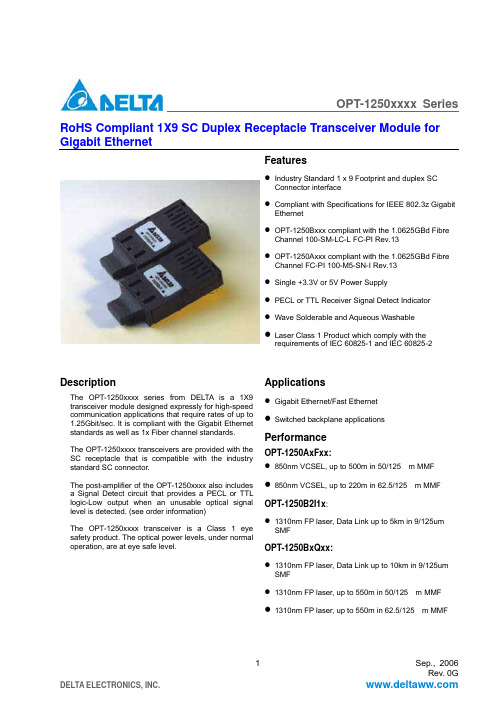
OPT-1250xxxx Series RoHS Compliant 1X9 SC Duplex Receptacle Transceiver Module for Gigabit EthernetFeaturesIndustry Standard 1 x 9 Footprint and duplex SCConnector interfaceCompliant with Specifications for IEEE 802.3z GigabitEthernetOPT-1250Bxxx compliant with the 1.0625GBd FibreChannel 100-SM-LC-L FC-PI Rev.13OPT-1250Axxx compliant with the 1.0625GBd FibreChannel FC-PI 100-M5-SN-I Rev.13Single +3.3V or 5V Power SupplyPECL or TTL Receiver Signal Detect IndicatorWave Solderable and Aqueous WashableLaser Class 1 Product which comply with therequirements of IEC 60825-1 and IEC 60825-2DescriptionThe OPT-1250xxxx series from DELTA is a 1X9transceiver module designed expressly for high-speedcommunication applications that require rates of up to1.25Gbit/sec. It is compliant with the Gigabit Ethernetstandards as well as 1x Fiber channel standards.The OPT-1250xxxx transceivers are provided with theSC receptacle that is compatible with the industrystandard SC connector.The post-amplifier of the OPT-1250xxxx also includesa Signal Detect circuit that provides a PECL or TTLlogic-Low output when an unusable optical signallevel is detected. (see order information)The OPT-1250xxxx transceiver is a Class 1 eyesafety product. The optical power levels, under normaloperation, are at eye safe level.ApplicationsGigabit Ethernet/Fast EthernetSwitched backplane applicationsPerformanceOPT-1250AxFxx:850nm VCSEL, up to 500m in 50/125 m MMF850nm VCSEL, up to 220m in 62.5/125 m MMFOPT-1250B2I1x:1310nm FP laser, Data Link up to 5km in 9/125umSMFOPT-1250BxQxx:1310nm FP laser, Data Link up to 10km in 9/125umSMF1310nm FP laser, up to 550m in 50/125 m MMF1310nm FP laser, up to 550m in 62.5/125 m MMFOPT-1250xxxx SeriesAbsolute Maximum RatingsParameter Symbol Min.Typ.Max.UnitNote Storage Temperature Ts -40 85 ºCLead Soldering Temperature T SOLD 260 ºCLead Soldering Time t SOLD10 sec.Supply Voltage V CC 0 6 VRecommended Operating ConditionsParameter Symbol Min.Typ.Max.UnitNote Ambient Operating Temperature T A 0 70 ºC 1Supply VoltageOPT-1250x1xxOPT-1250x2xx, OPT-1250x4xx V CC 4.753.1355.253.465VNote: See ordering information for detailElectrical Characteristics(At recommended ambient operating temperature, T A and supply voltage, V CC)Parameter Symbol Min.Typ.Max.UnitNote Total Supply Current I CCT300 mATransmitterTransmitter Data Input Voltage-Low V IL-V CC-1.810 -1.475V 1 Transmitter Data Input Voltage-High V IH-V CC-1.165 -0.880V 1 Transmitter Differential Input Voltage V DT0.3 1.6 V 2 ReceiverData Output Voltage-Low V OL-V CC-1.95 -1.62 V 1Data Output Voltage-High V OH-V CC-1.045 -0.74 V 1Receiver Differential Output Voltage V DR 0.5 0.7 1.2 V 2Output Data Rise/Fall Time t r/t f0.4 ns 3PECL SD OutputLOW level output voltage HIGH level output voltage V SDH-V CCV SDL-V CC-1.84-1.1-1.60-0.9V 4TTL SD OutputLOW level output voltage HIGH level output voltage V SDHV SDL2V CC0.8V 5Notes:1. For OPT-1250A1F1x, OPT-1250A4F1x, OPT-1250B2I1x, OPT-1250B2Q1x andOPT-1250B1Q1x.2. For OPT-1250A2F2x and OPT-1250B4Q2x.3. These are 20%~80% values4. For OPT-1250A1F1x, OPT-1250A2F2x, OPT-1250B2I1x, OPT-1250B1Q1x and OPT-1250B2Q1x5. For OPT-1250A4F1x and OPT-1250B4Q2xOPT-1250xxxx SeriesSingle Mode Transceiver (OPT-1250B2I1x, OPT-1250B1Q1x, OPT-1250B2Q1x,OPT-1250B4Q2x)(At recommended ambient operating temperature, T A and supply voltage, V CC; Data Rate=1.25Gb/sec,PRBS=27-1 NRZ, 9/125um SMF)Parameter SymbolMin.Typ.Max.UnitNote TransmitterOutput Optical Power (Avg.)OPT-1250BxIx OPT-1250BxQx P O-12-9.5-3-3dBmOptical Extinction Ratio ER 9 dBCenter Wavelength C 1270 1310 1355 nmSpectral Width (RMS) 2.8 nm Optical Rise/Fall time t r/t f0.26ns1 Relative Intensity Noise RIN -120dB/HzOutput Eye Complies with the IEEE 802.3z/D2 specification, and is class 1 laser eye safetyReceiverSensitivity (Avg.) P IN-19dBm2 Input Optical Wavelength 1310 nmSignal Detect-Asserted (Avg.) P A-19dBm Signal Detect-De-asserted (Avg.) P D -35 dBmSignal Detect-Hysteresis P A-P D 0.5 dBReceiver saturation power P SAT -3 dBm Notes:6. These are 20%~80% values7. The sensitivity is provided at a BER of 1×10⁻¹⁰ or better with an input signal consisting of1250Mb/s, 27-1 PRBS.Mask of the eye diagram for the optical transmit signalOPT-1250xxxx SeriesMulti-Mode Series Transceiver (OPT-1250A1F1x, OPT-1250A2F2x, OPT-1250A4F1x)(At recommended ambient operating temperature, T A and supply voltage, V CC; Data Rate=1.25Gb/sec,PRBS=27-1 NRZ, 62.5/125um MMF)Parameter SymbolMin.Typ.Max.UnitNote TransmitterOutput Optical Power (Avg.) P O -9.5 -4dBmOptical Extinction Ratio ER 9 dBCenter Wavelength C 830 850 860 nmSpectral Width (RMS) 0.85nmOptical Rise/Fall time t r/t f0.26ns1 Relative Intensity Noise RIN -117dB/HzOutput Eye Complies with the IEEE 802.3z/D2 specification, and is class 1 laser eye safetyReceiverSensitivity (Avg.) P IN-17dBm2 Input Optical Wavelength 850 nmSignal Detect-Asserted (Avg.) P A-17dBm Signal Detect-De-asserted (Avg.) P D -30 dBmSignal Detect-Hysteresis P A-P D 0.5 dBReceiver saturation power P SAT -4 dBm Notes:8. These are 20%~80% values9. The sensitivity is provided at a BER of 1×10⁻¹⁰ or better with an input signal consisting of1250Mb/s, 27-1 PRBS.Mask of the eye diagram for the optical transmit signalOPT-1250xxxx SeriesPin Out TabledescriptionFunctionalPIN Symbol1 GND Receiver Signal Ground2 RD (+) Receiver Data Out (LVPECL)3 RD (-) Receiver Data Out Bar (LVPECL)4 SD Receiver Signal Detect (LVPECL or TTL)5 VccR Receiver Power Supply,6 VccT Transmitter Power Supply7 TD (-) Transmitter Data In Bar (LVPECL)8 TD (+) Transmitter Data In (LVPECL)9 GND Transmitter Signal GroundPin Descriptions:Pin 1 Receiver Signal Ground, GNDDirectly connect these pins to the ground plane.Pin 2 Receiver Data Out (LVPECL), RD (+)Receiver Data output (LVPECL), RD (+).Pin 3 Receiver Data Out Bar (LVPECL), RD (-)Receiver Data output (LVPECL), RD (-).Pin 4 Receiver Signal Detect (LVPECL/TTL), SDPECL/TTL logic family. Normal Operation: Logic “1” OutputFault Condition: Logic”0” Output.Pin 5 Receiver Power Supply, VccRProvide +3.3/5V dc power supply.Pin 6 Transmitter Power Supply, VccTProvide +3.3/5V dc power supply.Pin 7 Transmitter Data In Bar (LVPECL), TD (-)Transmitter Data Input (LVPECL), TD (-)Pin 8 Transmitter Data In (LVPECL), TD (+)Transmitter Data Input (LVPECL), TD (+)Pin 9 Transmitter Signal Ground, GNDDirectly connect these pins to the ground plane.OPT-1250xxxx Series Package Outline Drawing (without shielding)Package Outline Drawing (A type shielding)OPT-1250xxxx Series Package Outline Drawing (B type shielding)Package Outline Drawing (C type shielding)OPT-1250xxxx SeriesRegulatory ComplianceFeature Reference PerformanceElectromagnetic Interference (EMI)FCC Class BEN 55022 Class B (CISPR 22A)Radio Frequency Electromagnetic Field EN 61000-4-3 IEC 1000-4-3Electrostatic Discharge to the Duplex LC Receptacle EN 61000-4-2 IEC 1000-4-2 IEC 801.2Electrostatic Discharge to the Electrical Pins MIL-STD-883E Method 3015.7(1) Satisfied with electricalcharacteristics of productspec.(2) No physical damageEye Safety US FDA CDRH AEL Class 1EN 60950: 2000EN 60825-1: 1994+A11+A2EN 60825-2: 2000 CDRH File # 0321539-00TUV Certificate No. R50032471Component Recognition Underwriters Laboratories andCanadian Standards Association JointComponent Recognition for InformationTechnology Equipment IncludingElectrical Business EquipmentUL File # E239394OPT-1250xxxx SeriesOrdering informationOPT- 1250X 1X 2X 3X 4X 5X 6X 7X 1: FiberA : Multi-mode 850nmB : Single-mode 1310nmX 5:RoHS CompliantBlank : Non-RoHS Compliant R : RoHS CompliantX 2: Power Supply Voltage and SD Level1: 5.0V, PECL SD Level 2: 3.3V, PECL SD Level 4: 3.3V, TTL SD LevelX 6: Shielding TypeBlank : Plastic housing A : A type shielding B : B type shielding C : C type shielding X 3:X 4:DistanceF : 500m, 50/125 m MMFI : 5km, 9/125 m SMF Q : 10km, 9/125 m SMFData Coupling 1: 1x9SC DC/DC 2: 1x9SC AC/ACX 7:TemperatureBlank : 0 to +70 degree C H : -10 to + 85 degree C。
ABB 1250A 说明书

!"#$% UniSwitch-CBW=12kV 1250A!"#$!"#$%&'( !"#$%&'()*+,-./0!"#$%&'( !"#$%&'()*+,-./0 1!"#$%&'()*+,-./0%12,345-678!"#$%&'() !"#$%&'!!"#$%&'()*+,-*./012!"#$%&'()*+,-.,/012345678!"#$%&'()*+,- !"#$%&'( )*+!"#$%&'()*+,-./0123 !45!67839:;!"#$%&'()*+,-'./012/345!"#41 !"#KKKKKKKKKKKKKKKKKKKKKKKKKKKKKKKKKKKKKKKKKKKKKKK 51.1 KKKKKKKKKKKKKKKKKKKKKKKKKKKKKKKKKKKKKKKKKKKKKKKKKKKK 51.2 !"KKKKKKKKKKKKKKKKKKKKKKKKKKKKKKKKKKKKKKKKK 51.3 !"#KKKKKKKKKKKKKKKKKKKKKKKKKKKKKKKKKKKKK 52 !KKKKKKKKKKKKKKKKKKKKKKKKKKKKKKKKKKKKKKKKKKKKKKKKKKKKKK 62.1 !KKKKKKKKKKKKKKKKKKKKKKKKKKKKKKKKKKKKKKKKKKKKK 62.2 !KKKKKKKKKKKKKKKKKKKKKKKKKKKKKKKKKKKKKKKKKKKKK 63 !"KKKKKKKKKKKKKKKKKKKKKKKKKKKKKKKKKKKKKKKKKKKKKKKKKK 73.1 KKKKKKKKKKKKKKKKKKKKKKKKKKKKKKKKKKKKKKKKKKKKKKKKKKKK 73.2 !"KKKKKKKKKKKKKKKKKKKKKKKKKKKKKKKKKKKKKKKKK 73.3 KKKKKKKKKKKKKKKKKKKKKKKKKKKKKKKKKKKKKKKKKKKKKKKKKKKK 84 !"KKKKKKKKKKKKKKKKKKKKKKKKKKKKKKKKKKKKKKKKKKKKKKKKKK 94.1 KKKKKKKKKKKKKKKKKKKKKKKKKKKKKKKKKKKKKKKKKKKKKKKK 94.2 !"#$KKKKKKKKKKKKKKKKKKKKKKKKKKKKKKK 104.3 !"#$KKKKKKKKKKKKKKKKKKKKKKKKKKKKKKK 104.4.1 !"#$%&'(KKKKKKKKKKKKKKKKK 104.4.2saQ !"#KKKKKKKKKKKKKKKKKKKKKKKKKKKK 114.4.3 !KKKKKKKKKKKKKKKKKKKKKKKKKKKKKKKKKKKKKKKKKKK 134.4.4 !"KKKKKKKKKKKKKKKKKKKKKKKKKKKKKKKKKKKKKKK 135 !"KKKKKKKKKKKKKKKKKKKKKKKKKKKKKKKKKKKKKKKKKKKKKKKK 146 !KKKKKKKKKKKKKKKKKKKKKKKKKKKKKKKKKKKKKKKKKKKKKKKKKKKK15UniSwitch-CBW= !"#1.1råápïáíÅÜJ`_t I= !"#$%&'()! !"#$%&'() NOhsRMeò !"#$% !"#$%&'!"# !"# råápïáíÅÜ!"# !"# !"#$!"#$%&'()1.2 !"d_PVMSJNVVN=PJPRâs !"#$%&'d_LqNNMOOJNVVV= !"#$%&"#'()*+!d_NVUQJOMMP= !"#$aiLqQMQJNVVT= !"#$%&'()*+,d_NVURJOMMQ= !"#$%&'($%1.3 !"#1. IEC !"#$%&'()*52.1 !"#2. UniSwitch !"#$= !"#$%2.2 !==X== ==X== ==========ãã===========SRM=x=NOUM=x NUUR63.1råápïáíÅÜ `_t !"#$%& ' !! ! !"#$% ! !! !"#$%Oãã !"#$%!"#$%&'()* !"#$%&'()!"#$%&'()*+,-./0 1234!"#$3.2 !"783.3NKG= !"#$%&' !"#$ !"#$ !"#$%&'() !"#$%&'(G= !"# L !"#$%&'()*+ !"#OK !"#$==== !"#$%G= !"#$%&'()*+,-. ,/0123 !" !"#$%&'() !"# !"#$G= !"#$%&'()*+,-./ !" !" !"#$ !"#$L ! !" !"#G= !"#$%#&'()*+,-./ !" !"#$%&'()*+, !"#$%& !"#$%&'("#)G= !"#$%&'()*+ !"#$%& !"##$%&G= !"#$%&'PK G= !"#$%&'()*+, !"#$% !"#$ !"#$%&'()*'+"#,)-G= !"#$%&$'()*+,-./G= !"#$pm^gNQM obuRON !"#$ QK !"#G= !"#$%&'()*+, !"#$%L !"#$% &'$% "#()L !"G= !"L !"#$%&'()*%&+, !G= !"#$%&'( !"#$L ! !"#G= !"#$%&'()L !"#$ !% !"#$%&'G= !"#$%& !"#$% !"#G= !"#$%&'( !"#$%&G= !"#$% !"#$%&G=!"#$%& !"L !"#$% &L !"#$4.1!!"#råápïáíÅÜ `_t9104.2 !"#$G= !"#$%&'#()*+,- !"# !"#$%&'(Nãã !"#$%&'G= !"#$%&'( !" !"#$ !" !"#$%&'()G= !"#$%&'()*+,#-. !"#G= !"#$% !"#$%&'()*+,4.3 !"#$G= !"#$%&'() !"#$%&'(G= !"#$ !"# !" !"G= !"#$%!"&'()!*G= !"#$%&'()*+ !"#G= !"#$ !"#$%&"'()*+, !"G= !"#$%&' !"#$%&'()*!"W= !"#$%&' !"#$% !"#$%&'G=G= !G= !G= !"#G= !G= !"4.4.1 !"#$%&'(4.4.1.1= L !"#$% !&'()%NF= !"#$%#&'() OF= !"# PF= !"#$%&' QF= !"#$ %&' RF= !"#$%&'(OM !"#$% !"#$%&'() SF=!"#$TF=!"#$ ! !"#== !"114.4.1.2 !"#$%&'()L !G== !"#$%&' G== !"#$%&'()#*+,'-./01!"#$%&'()*+,- !"#$% !"#$%&'() !"#$%&' !"#$%&'( !"#$%&'() !"#$%&'()"#$*+,-./0124.4.1.3= L !"#$%&'()*+!"#$%&'()$*+,-./01234 !"# !"#$%&'()*+),-!"#$%&'() !"#$ % !"#$ !NF !"#$OF= !"#$%& !"#$%&'()*+PF= !"#$%&'()*+,-./01234 !!"#$%&'(!"!#$%QF= !"#$%& !"#$%&'() !"# $% !"#$ !"#$%&RF= !" !"#$%&'()*+,-. !"#$%&4.4.1.4 !"#$%&'()*+,-L !!W= QKQKNKP !"#$%&'()*4.4.2==saQ !"#4.4.2.1 !"!!"#$%&'()* !"#$% !"#$%&'()* !"#$%&'( !"#!"#$%&'()*+ !"#$#%& !"#OR !"#$%&' !"!"#$%& !"#$%&'()*== !"#$%!!124.4.2.3= !G= !"#$%&'()*+,-.,/ !"# ! !" !"#$%&#'()*+, !!4.4.2.2= !"#$%#!G= !"#$%&'()*+,-.'/0123#!"#$%&'()*+G !"#$%&'()G !"#$%&'(!"#$%&' !"#$%&' ()* !"#$!"#$%&'()*+,-./0 &12( !"#$%&'()*+,-./01#$%2 !"#G !"#$ %& !"#$%&'()*+!"#$%&'()*+,-. ! "#G !"#$%&'134.4.3 !!"#$%L !"#$%& !"# !"# !"#$% &'( ! !G !"#$% &'( !"#$%&'(VM !"# $%&'() !"#$% ! !"#$%&'() !"# $% ! !"#$%&$'(G= !"#$%&'()*+G= !"#$ !"#$%&'()* !"G= !"#$%!"&'()*+,-./01 !"#$%&'()*+,-G= !"#$%&'()*)+!,-./0!123!"#$%&'()*+,-./01 !"#$%&!"#$%&'!()!"#$%#$&'4.4.4= !"!"#$%&'()*+,-./ sfp fb`=SNOQPJR !"#JJJJ ! "=aukJq !"#$%&'()*+,- JJJ=P !"# !"#$JJJ=PJJJN !"#$%&!"#$!%L !"#$%&' ( !"#$!%==!"#$%5. !"G=`_t !" #$%&' !"#^__!"#$%&'()*+,-G= !"#$%&'() !"#$%&'()!"#$%& !"#$%&'()*G= !"#$%&' !"#$%&'() *!" !"#$%&'( !"#$%!"#$%&'"()*+,-. !"#!"#$G= !"#$%&'()* !"#$%G= !"#RRMâd146. !15!" !"#$%&'ABB !"#$%&'!"#$%&'() 12(010) 6781 8000 (010) 6781 8001 100176!"! 1Y V A 000036 - c n 2008-02(021) 6122 8888 (021) 6122 8822(0571) 8790 1355 (0571) 8790 1151(025) 8664 5645 (025) 8664 5338(0755) 8831 3088 (0755) 8831 3033(0531) 8609 2726 (0531) 8609 2724(0532) 8502 6396 (0532) 8502 6395(0371) 6771 3588 (0371) 6771 3873(0769) 280 6366 (0769) 280 6367!"#!10 !" (010) 8456 6688 (010) 8456 7613 100016(027) 8725 9222 (027) 8725 9233(029) 8575 8288 (029) 8575 8299(028) 8526 8800 (028) 8526 8900(023) 6282 6688 (023) 6280 5369(0431) 8862 0866 (0431) 8862 0899(0510) 279 1133 (0510) 279 1236(852) 2929 3838 (852) 2929 3553(022) 8319 1801 (022) 8319 1802(024) 2334 1818 (024) 2334 1306(0451) 8287 6400 (0451) 8287 6404(0411) 8899 3355 (0411) 8899 3359(0592) 602 6033 (0592) 571 7769(0591) 8785 8224 (0591) 8781 4889(0574) 8731 5290 (0574) 8731 8179(020) 3785 0688 (020) 3785 0608(0551) 384 9700 (0551) 384 9707(0871) 315 8188 (0871) 315 8186(0771) 236 8316 (0771) 236 8308!(0471) 691 6330 (0471) 691 6331(0731) 268 3088 (0731) 444 5519(0351) 868 9292 (0351) 868 9200!(0991) 283 4455 (0592) 281 8240。
样本册-滤波器140507
插入损耗 插入耗损是在标准50Ω系统条件下测定的
FLAC32-3A
FLAC32-6A
共模
差模
FLAC12B-3WE
FLAC12B-6WE
外形尺寸 单位(mm) FLAC32-3A FLAC32-6A FLAC12B-3WE FLAC12B-6WE
电路图原理图
10
单相D系列滤波器
产品特点 良好的共模、差模抑制性,能有效的抑制线-线、 线-地之间的电磁干扰。 灵活的安装方式 满足UL & ENEC的认证
声明 本书中所列技术参数仅供参考,技术参数如有变化恕不另行通知,请以实物及产品《技术规格书》为准,详情请联系
中石公司。
5
JONES 单相电源滤波器
单相A系列滤波器
产品特点 良好的共模、差模抑制性,能有效的抑制线-线、 线-地之间的电磁干扰。 低泄漏电流 灵活的安装方式 满足UL & ENEC的认证
6A
10A
1768VDC/1min
115/250
<0.5mA@250VAC, (line/line)
20A
50/60 Hz
VAC
50Hz
2000VAC/1min
30A
(lines/case)
6A
FLHDB3H-10LL
10A
FLHDM3H-10LL
10A
气候类别 25/85/21
插入损耗 插入耗损是在标准50Ω系统条件下测定的
d1B00
50
0
0.01
0.10
1.00
10
0
100MHz
0.01
0.10
1.00
10
100MHz
FLHD01-6A
NAMUR接口1 4英寸和1 2英寸高流气动阀G1 4英寸和G1 2英寸用于控制空气驱动器应用说明书

aerospace climate control electromechanical filtrationfluid & gas handling hydraulics pneumatics process control sealing & shieldingD2D1"2""4"MFTD4D3Ra 3.2Description of ApplicationsControl of single or double acting pneumatic actuators, in safe or dangerous areas.NAMUR Interfaces 1/4" & 1/2"Th e interface design is conform to the NAMURstandard and to the VDI/VDE 3845 recommendations of the actuator industry. It allows a compact design of the actuator/valve unit. In case of a 3/2 function,the air of the actuator spring chamber also fl owsthrough the pilot valve (re-breather function).Th is prevents corrosion of the actuator springs.Market DescriptionProcess industriesChemical, Petrochemical industries Oil & GasWater & Sewage Pulp & Paper Food & BeveragePharmaceutical industryPowder Dosing-Transportation Air DryersF T D1 D2 D3 D4 min. M mm mm mm Mm mm M5 1/4 32 24 8 12 M5 M6 1/2 45 40 10 16 M6F: 2 mounting holes - T: 2 actuators control port - M: 2 holes for dowel pins● High fl ow: 1.250 l/min (1/4"), 3.000 l/min (1/2")● Compact design ● Long life expectancy● N3x series compatible with any Parker Lucifer coil(ATEX or not) of electrical group 2 (8/9 W coils)● Fail safe standard● Reduced inventory (3/2 & 5/2 functions with the samevalve on 341Nx5 series)● Mechanical part of the valve ATEX certifi ed accordingstandard EN 13463-1 & -5Function: 3/2 , 5/2, 3/2 <=> 5/2 and 5/3 valves.Manual override: Standard on all versions.Design: Solenoid operated spool valve with combined spring and air return & external air pressure operated versions.Mounting:For direct mounting on NAMUR interface ¼" & ½".Mounting position: I ndifferent.Material specifi cations: Aluminium body. Internal parts from stainless steel.Sealing material from NBR.Range of admissible pressure drop: Δp min. = see table. Δp max. = 10 bar.Media:Dry or lubricated air.Fluid temperature: Min. 0°C Max. + 50°C Ambient temperature: -10°C to +50°CElectrical part: N0x series are compatible with 22mm coil 496131 / 496482 / 496637 SeriesN3x series are compatible with 32/37/40 mm coils part of electrical group 2 (8/9W), including 481865 / 495870 / 495905 Series.Solenoid duty: 100% ED.Voltage: 481865 coil: 12 VDC , 24 VDC , 48 VDC , 110VDC, 24 V / 50 AC, 48 V / 50 AC,110 V / 50 AC, 220-230V/50 AC, 115 V / 60 Hz AC, 230 V / 60 AC.Voltage tolerance: ± 10% of nominal for 481865 coil.Class of insulation material: Class F for 481865 coil.Standards:Mechanical ATEX conform to EN 13463-1 & -5.Customer Value PropositionGeneral Information1313135135135135135G1/4" SeriesSolenoid Operated VersionsN03-N05 Series with 22 mm Coil3/2 Solenoid operated - Combined spring & air return (monostable)1/4 7 1250 2.5 10 10 50 NBR 331N03 - 496131 3 3 300 11/4 7 1250 2.5 10 10 50 NBR 331N03 - 496482 3 3 300 11/4 7 1250 2.5 10 10 50 NBR 331N03 - 496637 3 3 30015/2 Solenoid operated - Combined spring & air return (monostable)1/4 7 1250 2.5 10 10 50NBR 341N03 - 496131 3 3 300 21/4 7 1250 2.5 10 10 50 NBR 341N03 - 496482 3 3 300 2 1/47 1250 2.5 10 1050NBR 341N03 - 496637 3 3 30023/2 <=> 5/2 with conversion plate - Solenoid operated Combined spring & air return (monostable)1/4 7 1250 2.5 10 10 50NBR 341N05 - 496131 3 3 310 3 1/4 7 1250 2.5 10 10 50 NBR 341N05 - 496482 3 3 310 3 1/47 1250 2.5 10 1050NBR 341N05 - 496637 3 3 31035/2 Solenoid operated and return (bistable)1/47 1250 2.5 10 10 50NBR 347N03 - 496131 3 3 430 41/4 7 1250 2.5 10 10 50 NBR 347N03 - 496482 3 3 430 4 1/47 1250 2.5 10 1050NBR 347N03 - 496637 3 3 43045/3 W1 closed in center position - Solenoid operated and return1/4 7 1250 2.5 10 10 50NBR 342N03 - 496131 3 3 430 41/4 7 1250 2.5 10 10 50 NBR 342N03 - 496482 3 3 430 4 1/47 1250 2.5 10 1050NBR 342N03 - 496637 3 3 43045/3 W3 exhausted in center position Solenoid operated and return (bistable)1/4 7 1250 2.5 10 10 50NBR 343N03 - 496131 3 3 430 41/4 7 1250 2.5 10 10 50 NBR 343N03 - 496482 3 3 430 4 1/47 1250 2.5 10 1050NBR 343N03 - 496637 3 3 4304Please consult the "How to Order" part at the end of each coil chapter.Dimensions Reference 3Dimensions Reference 4404040403232322222222232326767676767505050505013 13 13 13 13 13 13 13 44 44 44 222236.536.5G1/4" (2x)G1/4" (3x)G1/4" (3x)G1/4" (3x)M5M5M5M52323232336,52424242423232323868610290 121414101212344355513332227.27.27.27.2Dimensions Reference 1Dimensions Reference 2131351351352440403232879738381313 19.519.513132222 24243232DIN 43650ADIN 43650A G1/8"G1/8"2222 1001302323232324 24 14 12245533G1/4" (3x)G1/4" (3x)M5M52222327.27.5Solenoid Operated VersionsN33-N35 Series with 32 / 37 / 40 mm CoilAdmissible Max. admissible differential fl uidPort size Orifi ce Q N pressure temperatureSeat Reference Consumption Weight Elect. Dim. (bar) (ºC)disc number Power (g) Group Ref.(Watt) max. Min. = 0ºC G mm L/min min DC= AC~ Air & Valve Housing Coil DC AC Neutral gases3/2 <=> 5/2 with conversion plate - Solenoid operated Combined spring & air return (monostable)1/4 7 1250 2.5 10 10 50NBR 341N35 2995 481865 9 8 480 2 5 1/4 7 1250 2.5 10 10 50 NBR - 2995 495870 9 8 700 - 2 1/47 1250 2.5 10 1050NBR - - 495905 8 8 740 - 25/2 Solenoid operated and return (bistable)1/47 1250 2.5 10 10 50NBR 347N33 2995 481865 9 8 750 2 6 1/4 7 1250 2.5 10 10 50 NBR - 2995 495870 9 8 1190 2 - 1/47 1250 2.5 10 1050NBR - - 495905 8 8 1270 2 -5/3 W1 closed in center positionSolenoid operated and return (bistable)1/4 7 1250 2.5 10 10 50NBR 342N33 2995 481865 9 8 750 2 6 1/4 7 1250 2.5 10 10 50 NBR - 2995 495870 9 8 1190 2 - 1/47 1250 2.5 10 1050NBR - - 495905 8 8 1270 2 -Please consult the "How to Order" part at the end of each coil chapter.Dimensions Reference 5Dimensions Reference 61313513513540404032323213 13 13 13131344 22 22 22 22 86868623232323232324 24 24 355133G1/4" (2x)G1/4" (3x)G1/4" (3x)G1/8G1/8G1/8M5M5M52222227.27.27.2External Pressure Air Operated Series 5xx N03 SeriesAdmissible Max. admissible differential fl uidPort size Orifi ce Q N pressure temperatureSeat Reference Consumption Weight Dimensions (bar) (ºC)disc number Power (g) Reference(Watt) max. Min. = 0ºC G mm L/min min DC= AC~ Air & Valve Housing Coil DC AC Neutral gases3/2 External pressure air operatedCombined spring & air return (monostable)External pressure supply 2.5 to 10 bar1/4 7 1250 2.5 10 10 50 NBR 531N03 - w/o - - 21075/2 external pressure air operatedCombined spring & air return (monostable)External pressure supply 2.5 to 10 bar1/47 1250 2.5 10 1050NBR 541N03 - w/o - - 21085/2 external pressure air operatedExternal pressure air return (bistable)External pressure supply 2.5 to 10 bar1/47 1250 2.5 10 1050NBR 547N03 - w/o - - 24095/3 W1 closed in center position - External pressure air operatedExternal pressure air return (bistable)External pressure supply 2.5 to 10 bar1/47 1250 2.5 10 1050NBR 542N03 - w/o - - 2409Dimensions Reference 7Dimensions Reference 8Dimensions Reference 913135135Solenoid Operated VersionsN34 Series with 32 / 37 / 40 mm CoilAdmissible Max. admissible differential fl uidPort size Orifi ce Q N pressure temperatureSeat Reference Consumption Weight Elect. Dim. (bar) (ºC)disc number Power (g) Group Ref.(Watt) max. Min. = 0ºC G mm L/min min DC= AC~ Air & Valve Housing Coil DC AC Neutral gases3/2 Solenoid operatedCombined spring & air return (monostable)1/2 12 3000 2.5 10 10 50NBR 331N34 2995 481865 9 8 910 2 10 1/2 12 3000 2.5 10 10 50 NBR - 2995 495870 9 8 1130 2 - 1/212 3000 2.5 10 1050NBR - - 495905 8 8 1170 2 -5/2 Solenoid operatedCombined spring & air return (monostable)1/2 12 3000 2.5 10 10 50NBR 341N34 2995 481865 9 8 900 2 11 1/2 12 3000 2.5 10 10 50 NBR - 2995 495870 9 8 1120 2 - 1/212 3000 2.5 10 1050NBR - - 495905 8 8 1160 2 -5/2 Solenoid operated and return (bistable)1/212 3000 2.5 10 10 50NBR 347N34 2995 481865 9 8 1240 2 12 1/2 12 3000 2.5 10 10 50 NBR - 2995 495870 9 8 1680 2 - 1/212 3000 2.5 10 1050NBR - - 495905 8 8 1760 2 -Please consult the "How to Order" part at the end of each coil chapter.Dimensions Reference 10Dimensions Reference 11Dimensions Reference 1213135External Pressure Air Operated Series5 xx N04 SeriesAdmissible Max. admissibledifferential fl uidPortsize Orifi ce QNpressure temperatureSeat ReferenceConsumptionWeightDimensions(bar)(ºC)disc number Power (g)Reference(Watt)max. Min. = 0ºCG mm L/min min DC= AC~ Air & Valve Housing Coil DC ACNeutralgases3/2 External pressure air operatedCombined spring & air return (monostable)External pressure supply 2.5 to 10 bar1/2 1230002.510 10 50 NBR531N04 - w/o - - 620 135/2 external pressure air operatedCombined spring & air return (monostable)External pressure supply 2.5 to 10 bar1/2 12 3000 2.5 10 10 50 NBR541N04 - w/o - - 600 14 Dimensions Reference 13Dimensions Reference 14● Power: 3W● Insulation Class: F (155°C)● Degree of Protection: IP65 (with plug)● Duty Cycle: 100% ED ●Ambient Temperature:-10°C to 50°C3 different types are available:● Ref. 496131for a safe area without plug ● Ref. 496482for a safe area with plug ● Ref. 496637for an ATEX area Zone 22Coils and Spare Parts Informations 496637 coil series with connection 2P + G when mounted together with the supplied Pg9 plug (delivered with the coil) are suitable for use in dangerous areas (dust Zone 22) according to the European directive ATEX 94/9/C. Protection mode: Ex tD A22 IP65 - T95°CAvailable Safe area Safe area ATEX Voltageswithout DIN plug with DIN plug Zone 22 EX II 3DOrder Order Order Code Code Code12VDC 496131 C1 496482 C1 496637 C124VDC 496131 C2 496482 C2 496637 C2 48VDC 496131 C4 496482 C4 496637 C4 110VDC 496131 C5 496482 C5 496637 C5 24/50-60VAC 496131 P0 496482 P0 496637 P0 48/50-60VAC 496131 S4 496482 S4 496637 S4 110/50-60VAC 496131 P2 496482 P2 496637 P2 115/60VAC 496131 K8 496482 K8 496637 K8230/50-60VAC 496131 P9496482 P9496637 P9How to OrderThe housing kit is already included into the coil reference, so it’s not needed to add it in the order code:Valve Reference Number - Coil Reference - Voltage code = Order codeExample: 341N03 - 496131 C2Valves and coils may be ordered also separately.Coils 22 mm for N03-N05 SeriesSafe Area & ATEX Zone 22 Ref. 496131 / 496482 / 496637Th ese coils with connection for 2 P+G DIN 43650 B plug are encapsulated in synthetic material, conform to the IEC/CENELEC safety standards and comply with European low voltage directive73/23/EC .S a f e A r e a & A T E X Z o n e 22● Power: 8W (AC) 9W (DC)● Insulation Class: F (155°C)● Degree of Protection: IP65 (with plug)● Duty Cycle: 100% ED● Voltage Tolerance -10%/+10%● Ambient Temperature -40°C/+50°C◗ The application can be limited alsoby the temperature range of the valveAvailable Order Voltages Code 12VDC 481865 C1 24VDC 481865 C2 48VDC 481865 C4 110VDC 481865 C5 24/50VAC 481865 A2 48/50VAC 481865 A4 110/50VAC 481865 A5 220-230/50VAC 481865 3D 380/50VAC 481865 A9 24/60VAC 481865 B2 115/60VAC 481865 K8 230/60VAC481865 J3How to OrderThis coil must be used together with a housing kit which includes a nut, a plate, and a washer. Housing Kit Order Code: 2995Valve Reference Number - Housing Reference - Coil Reference - Voltage Code = Order CodeExample: 341N35 - 2995 - 481865 C2Coils 32 mm / 37 mm / 40 mm for N33-N34-N35 Series Safe Area Ref. 481865N3x series are compatible with any Parker Lucifer coil part of electrical group 2. Th at group includes many diff erent coils for safe areas or areas submitted to ATEX certifi cations. Th ese coils are of the 8/9W class. Th ese coils with connection for 2P+G DIN 43650 A plug are encapsulated in synthetic material, conform to the IEC/CENELEC safety standards and comply with European low voltage directive 73/23/EC.S a f e A r e adtCoils and Spare Parts Informations ●Power: 8W● Insulation Class: F (155°C)● Degree of Protection: IP67 (with 4538 housing)● Duty Cycle: 100%●Voltage Tolerance -10%/+10%● Ambient Temperature -40°C/+50°C ◗ The application can be limited alsoby the temperature range of the valveHow to OrderValve Reference Number - Housing Reference - Coil Reference - Voltage Code = Order CodeExample: 331N34 - 4538 - 481000C2Housing 4538This enclosure is dust and water proof. It corresponds to the protection degree IP67 according to IEC/EN60529. Corrosion resistant, the metallic housing offers good protection for the coil against shocks. It can be 360° orientable. This housing must be equipped with 481000 series coil.Material: galvanized passivated steel - Degree of protection IP67 according to IEC/EN 60529 - Electrical connection: cable connection by cable gland according to DIN46320. Cable with outer diameter 6.5-13.5 mm (M20x1.5) can be simply sealed using a rubber gland resilient sealing rings. The enclosure is internally and externally fi tted with grounding and earthing screw terminals.Coils 32 mm / 37 mm / 40 mm for N33-N34-N35 Series Safe Area Coil 481000 Series with 4538 Watertight and dust proof housing IP67 Ref. 481000Coil 481000 series is encapsulated in synthetic material. Electrical connection is made with screw terminals for wire up to 1.5 mm. Th is coil conforms to the IEC/CENELEC safety standards and complies with European low voltage directive 73/23/EC. It must be used with a metallic housing.S a f e A r e a●II 3 G - Ex nAC IIC T3 / T4● II 3 D - Ex tD A22 IP65 - T 195°C / T 130°C● Power: 8W (AC) 9W (DC)● Insulation Class: F (155°C)● Degree of Protection: IP65 (with plug)● Duty Cycle: 100% ED● Voltage Tolerance -10%/+10%●Ambient temperature◗ T3 (gaz) T 195°C (dust) -40°C/+65°C ◗ T4 (gaz) T 130°C (dust) -40°C/+50°C◗ The application can be limited alsoby the temperature range of the valveAvailable Order Voltages Code 24VDC 495870 C2 48VDC 495870 C4 110VDC 495870 C5 24/50VAC 495870 A2 48/50VAC 495870 A4 110/50VAC 495870 A5 220-230/50VAC495870 3DA T E X Z o n e 2-22How to OrderThis coil must be used together with a housing kit which includes a nut, a plate, and a washer. Housing kit order code: 2995Valve Reference Number - Coil Reference - Voltage code = Order codeExample: 331N34 - 2995 - 495870 A5Coils 32 mm / 37 mm / 40 mm for N33-N34-N35 Series ATEX Zone 2-22 Ref. 495870Th is coil with connection 2P+G - when mounted together with the supplied Pg 9 plug (delivered with the coil), is suitable for use in Gas and Dust dangerous areas (Zone 2-22), according to the European directive ATEX 94/9/C . Certifi cate LCIE 05 ATEX 6003 X - Protection mode: non sparking / limited energy solenoid0081II 3 G-DA T E X z o n e 1-21●II 2 G - Ex d mb IIC T4● II 2 D - Ex tD A21 IP67 - T 130°C● Insulation Class H (180°C)● Power: 8W (AC-DC)● Degree of Protection IP67● Duty Cycle 100%● Voltage Tolerance -10%/+10%● Ambient Temperature: -40°C/+65°C◗ The application can be limited alsoby the temperature range of the valveAvailable Order Voltages Code 24VDC 495905 C2 48VDC 495905 C4 110VDC 495905 C5 24/50VAC 495905 A2 48/50VAC 495905 A4 110/50VAC 495905 E5 220-230/50VAC 495905 3D115/60 495905 E5240/60 495905 B8Electric connection is done in the connection box on an easily accessible connector terminals.M20x1.5 Cable glandHow to OrderThe housing kit is already included into the coil reference, so it’s not needed to add it in the order code:Valve Reference Number - Coil Reference - Voltage code = Order codeExample: 347N33 - 495905 C2Coils 32 mm / 37 mm / 40 mm for N33-N34-N35 Series ATEX Zone 1-21 Ref. 495905Th is coil is suitable for use in Gas and Dust dangerous areas (Zone 1-21), according to the European directive ATEX 94/9/C . It’s also IECEx certifi ed according to the IECEx Scheme. Certifi cate LCIE 02 ATEX 6451 X - Protection modes: Explosionproof solenoids with fl ameproof enclosure / encapsulation "d mb"0081II 2 G/Dnct c io o n n bo ox al a l s.s .Available OrderOrder Voltages Code Code 6VDC 483371 C0 - 12VDC 483371 C1 - 24VDC 483371 C2 494040 C236VDC 483371 C3 - 48VDC 483371 C4 - 60VDC 483371 M3 - 110VDC 483371 C5 - 125VDC 483371 3N 494040 3N 220VDC 483371 C7 494040 C712/50VAC 483371 A1 - 24/50VAC 483371 A2 494040 A248/50VAC 483371 A4 - 110-115/50VAC 483371 OA 494040 OA 220-230/50 483371 3D 494040 3D24/60VAC 483371 B2 - 110-115/60VAC 483371 6J - 220-240/60VAC 483371 4K-380/50-440/60VAC -494040 5PHow to OrderThe housing kit is already included into the coil reference, so it’s not needed to add it in the order code:Valve Reference Number - Coil Reference - Voltage code = Order codeExample: 347N33 - 483371C2Coils 32 mm / 37 mm / 40 mm for N33-N34-N35 Series ATEX Solutions Zone 1-21 Ref. 483371 & 494040Th ese coils are suitable for use in Gas and Dust dangerous areas (Zone 1-21), according to the European directive ATEX 94/9/C. Protection mode:encapsulated electrical parts with increased safety.483371…DC: 24V / 400mA - 48V / 250mA 110V / 100mAAC: 24V / 630mA - 48V / 315mA 110/115V / 160mA 220/230V / 80mA494040…DC: 24V / 400mA - 125V / 80mA48V /220V - 63mAAC: 24V / 630mA - 48V / 315mA 110/115V / 160mA220/230V / 80mAA T E X Z o n e 1-21Reference 483371 or HZ06 494040 or HZ23Approval LCIE 02 ATEX 6011 X LCIE 02 ATEX 6013 X Type of Gas II 2 G - Ex e mb II T4 II 2 G - Ex e mb II T3 II 2 G - Ex e mb II T4 protection Dust II 2 D - Ex tD A21 T 130°C II 2 D - Ex tD A21 T 195°C II 2 D - Ex tD A21 T 130°C Degree of protection I P67 I P67 Ambiant temperature -40°C to +65°C -40°C to +90°C -40°C to +65°CThe application is limited also by the temperature range of the valveClass of insulation F (155°) H (180°) Electrical connection By special cable gland or M20x1.5 "Ex e" on screw terminals for wires up to 1.5 mm². Cables with outside diameter 6.5 mm to 13.5 mm can be simply sealed using the rubber gland with resilient sealing rings supplied. Elect. DC Pn (hot) 8 W 8 W Power P (cold) 20°C 9 W 9 W AC Pn (holding) 8 W 8 W 32 VA (9 W) 32 VA (9 W) Voltage tolerance Tolerance -10/ +10% of the nominal voltageSolenoid duty Continuous duty solenoid (ED 100%)Fuses: Both electrical 483371… and 494040… parts have to be connected in series with asafety fuse according to CEI 60127-3.Spare Parts Mounting Kit and AccessoriesExhaust Flow RegulatorsMaterial Body: Brass Filter element: Sintered bronze Spring: Stainless Steel Seal: NBRG1/8" Order code: 496551 G1/4" Order code: 496552 G1/2" Order code: 496553Kit for G1/4" Modelswithout conversion plate (N x 3 Series)Kit includes the 2 mounting screws M5 x 25 A2, the dowel pin M5 x 10 A2, the 2 O-rings NBR 15 x 2.5Order code: 496132Kit for G1/2" Models (N x 4 Series)Kit includes the 2 mounting screws M6 x 35 A2, the dowel pin M6 x 12 A2, the 2 O-rings NBR 24 x 3Order code: 496133Kit for G1/4" Modelswith conversion plate (N x 5 Series)Kit includes the 2 mounting screws M5 x 35 A2, the dowel pin M5 x 20 A2,the conversion plate equipped with its seals Order code:496742Connector for 32 mm CoilConnector DIN43650 AA Pg9 2P+E Order code: 486586Housing for 22 mm CoilPlastic nut with O-ring Order code: 3125Connector for 22 mm CoilConnector DIN43650 AB Pg9 2P+E Order code:481043NotesAEROSPACEKey Markets• Aircraft engines• Business & general aviation• Commercial transports• Land-based weapons systems• Military aircraft• Missiles & launch vehicles• Regional transports• Unmanned aerial vehiclesKey ProductsFlight control systems& compon ntsFluid conveyance systemsFluid metering delivery& atomization devicesFuel systems & componentsHydraulic systems & componentsInert nitrogen generating systemsPneumatic systems & components• Wheels & brakesCLIMATE CONTROLKey MarketsAgricultureAir conditioningFood, beverage & dairy• Life sciences & medicalPrecision coolingProcessingTransportationKey ProductsCO2 controlsElectronic controllersFilter driersHand shut-off valvesHose & fi ttingsPressure regulating valvesRefrigerant distributorsSafety relief valvesSolenoid valvesThermostatic expansion valvesFILTRATIONKey MarketsFood & beverageIndustrial machineryLife sciencesMarineMobile equipmentOil & gasPower generationProcessTransportationKey ProductsAnalytical gas generatorsCompressed air & gas fi ltersCondition monitoringEngine air, fuel & oil fi ltration& syst msHydraulic, lubrication& coolant fi ltersProcess, chemical, water& microfi ltration fi ltersNitrogen, hydrogen & zeroair g n ratorsELECTROMECHANICALKey MarketsAerospaceFactory automationFood & beverageLife science & medicalMachine tools• Packaging machinery• Paper machinery• Plastics machinery & converting• Primary metalsSemiconductor & electronics• TextileWire & cableKey Products• AC/DC drives & systemsElectric actuatorsGearheadsHuman machine interfacesIndustrial PCs• InvertersLinear motors, slides and stagesPrecision stages• Stepper motorsServo motors, drives & controlsStructural extrusionsPNEUMATICSKey Markets• Aerospace• Conveyor & material handling• Factory automation• Food & beverage• Life science & medical• Machine tools• Packaging machinery• Transportation & automotiveKey ProductsAir preparationCompact cylindersField bus valve systemsGrippersGuided cylindersManifoldsMiniature fl uidicsPneumatic accessoriesPneumatic actuators & grippersPneumatic valves and controlsRodless cylindersRotary actuatorsTie rod cylindersVacuum generators, cups & sensorsFLUID & GAS HANDLINGKey MarketsAerospaceAgricultureBulk chemical handlingConstruction machineryFood & beverageFuel & gas deliveryIndustrial machineryMobileOil & gasTransportationWeldingKey ProductsBrass fi ttings & valvesDiagnostic equipmentFluid conveyance systemsIndustrial hosePTFE & PFA hose, tubing& plastic fi ttingsRubber & thermoplastic hose& couplingsTube fi ttings & adaptersQuick disconnectsHYDRAULICSKey Markets• Aerospace• Aerial lift• Agriculture• Construction machinery• Forestry• Industrial machinery• Mining• Oil & gas• Power generation & energy• Truck hydraulicsKey Products• Diagnostic equipment• Hydraulic cylinders& accumulators• Hydraulic motors & pumps• Hydraulic systems• Hydraulic valves & controls• Power take-offs• Rubber & thermoplastic hose& couplings• Tube fi ttings & adapters• Quick disconnectsPROCESS CONTROLKey MarketsChemical & refi ningFood, beverage & dairyMedical & dentalMicroelectronicsOil & gasPower generationKey ProductsAnalytical sample conditioningproducts & systemsFluoropolymer chemical deliveryfi ttings, valves & pumpsHigh purity gas delivery fi ttings,valves & regulatorsInstrumentation fi ttings, valves& r gulatorsMedium pressure fi ttings & valvesProcess control manifoldsSEALING & SHIELDINGKey MarketsAerospaceChemical processingConsumerEnergy, oil & gasFluid powerGeneral industrialInformation technologyLife sciencesMilitarySemiconductorTelecommunicationsTransportationKey ProductsDynamic sealsElastomeric o-ringsEMI shieldingExtruded & precision-cut,fabricated elastomeric sealsHomogeneous & insertedlastom ric shap sHigh temperature metal sealsMetal & plastic retainedcomposit s alsThermal management Parker’s Motion & Control TechnologiesAt Parker, we’re guidedby a relentless drive to helpour customers become moreproductive and achievehigher levels of profi tabilityby engineering the bestsystems for their require-ments. It means looking atcustomer applications frommany angles to fi nd newways to create value.Whatever the motion andcontrol technology need,Parker has the experience,breadth of product and globalreach to consistently deliver.No company knows moreabout motion and controltechnology than Parker.For further info call00800 27 27 5374.AE – UAE, Dubai Tel: +971 4 8127100********************AR – Argentina, Buenos Aires Tel: +54 3327 44 4129AT – Austria, Wiener Neustadt Tel: +43 (0)2622 23501-0*************************AT – Eastern Europe, Wiener NeustadtTel: +43 (0)2622 23501 900****************************AU – Australia, Castle Hill Tel: +61 (0)2-9634 7777AZ – Azerbaijan, Baku Tel: +994 50 2233 458****************************BE/LU – Belgium, Nivelles Tel: +32 (0)67 280 900*************************BR – Brazil, Cachoeirinha RS Tel: +55 51 3470 9144BY – Belarus, Minsk Tel: +375 17 209 9399*************************CA – Canada, Milton, Ontario Tel: +1 905 693 3000CH – Switzerland, Etoy Tel: +41 (0)21 821 87 00*****************************CL – Chile, Santiago Tel: +56 2 623 1216CN – China, Shanghai Tel: +86 21 2899 5000CZ – Czech Republic, Klecany Tel: +420 284 083 111*******************************DE – Germany, Kaarst Tel: +49 (0)2131 4016 0*************************DK – Denmark, Ballerup Tel: +45 43 56 04 00*************************ES – Spain, Madrid Tel: +34 902 330 001***********************FI – Finland, Vantaa Tel: +358 (0)20 753 2500parker.fi ****************FR – France, Contamine s/ArveTel: +33 (0)4 50 25 80 25************************GR – Greece, Athens Tel: +30 210 933 6450************************HK – Hong Kong Tel: +852 2428 8008HU – Hungary, Budapest Tel: +36 1 220 4155*************************IE – Ireland, Dublin Tel: +353 (0)1 466 6370*************************IN – India, MumbaiTel: +91 22 6513 7081-85IT – Italy, Corsico (MI)Tel: +39 02 45 19 21***********************JP – Japan, Tokyo Tel: +81 (0)3 6408 3901KR – South Korea, Seoul Tel: +82 2 559 0400KZ – Kazakhstan, Almaty Tel: +7 7272 505 800****************************LV – Latvia, Riga Tel: +371 6 745 2601************************MX – Mexico, Apodaca Tel: +52 81 8156 6000MY – Malaysia, Shah Alam Tel: +60 3 7849 0800NL – The Netherlands, OldenzaalTel: +31 (0)541 585 000********************NO – Norway, Ski Tel: +47 64 91 10 00************************NZ – New Zealand, Mt Wellington Tel: +64 9 574 1744PL – Poland, Warsaw Tel: +48 (0)22 573 24 00************************PT – Portugal, Leca da Palmeira Tel: +351 22 999 7360**************************RO – Romania, Bucharest Tel: +40 21 252 1382*************************RU – Russia, Moscow Tel: +7 495 645-2156************************SE – Sweden, Spånga Tel: +46 (0)8 59 79 50 00************************SG – Singapore Tel: +65 6887 6300SK – Slovakia, Banská Bystrica Tel: +421 484 162 252**************************SL – Slovenia, Novo Mesto Tel: +386 7 337 6650**************************TH – Thailand, Bangkok Tel: +662 717 8140TR – Turkey, Istanbul Tel: +90 216 4997081************************TW – Taiwan, Taipei Tel: +886 2 2298 8987UA – Ukraine, Kiev Tel +380 44 494 2731*************************UK – United Kingdom, WarwickTel: +44 (0)1926 317 878********************US – USA, Cleveland Tel: +1 216 896 3000VE – Venezuela, Caracas Tel: +58 212 238 5422ZA – South Africa,Kempton ParkTel: +27 (0)11 961 0700*****************************Parker WorldwideEuropean Product Information Centre Free phone: 00 800 27 27 5374(from AT, BE, CH, CZ, DE, EE, ES, FI, FR, IE, IL, IS, IT, LU, MT, NL, NO, PT, SE, SK, UK)E d . 2010-06-08Parker Hannifi n Ltd. Tachbrook Park DriveTachbrook Park, Warwick CV34 6TU United KingdomTel.: +44 (0) 1926 317 878Catalogue 1101/UK - 06/2010 - TMCZ© 2010 Parker Hannifi n Corporation.All rights reserved.。
上机操作

3。 用户基本命令
〈DISPLAY-SUBSCR(4296):[DN=K‘XXXXXXX。 [EN=H‘XXXX&XX。
• 显示DN〈--〉EN • 显示用户MTR • 显示用户FAC
〈MODIFY-SUBSCR(4294):DN=K‘XXXXXXX, XXXX=XXXX。 相关修改参数 • 修改用户特性 • 相关参数举例 ** 呼叫观察(电话打完,输出观察报告)
〈MODIFY-ABD-FACILITY(140): DN= ,ABDREPSZ=10。 • 修改库容量ABDREPSZ 〈REMOVE-ABD-FACILITY(142): DN=K‘XXXXXXX。 • 删除某用户的ABD功能
(3)操作员帮助生成ABD对应关系 〈MODIFY-ABD-CODE(138):DN= , ABDCODE=XX,ABDDGTS=K‘0105800095。 • 用远控方式设置,较易成功 (4)显示缩位拨号对应关系 〈DISPLAY-ABD-REPERTRY(137): DN=K‘XXXXXXX。 • 显示库中内容(ABDCODE 〈==〉ABDDGTS)
(3) 操作实现 **1 AB 通话 ,A有呼叫等待权 **2 C 拨打A,A听等待音,C听回铃音 **31 A 不理睬,15秒后,等待音消失,C听阻 塞音 **32 A决定不理睬C,并去除等待音 拨 R + 0 等待音消失,C听阻塞音 **33 A放弃与B通话,转与C 通话 拨 R + 1 AC通43; 2 AC通话,B听保持音 (4) 远控删除 # 58 #
(5)用户远控过程 • 登记 * 51 * 缩位短码 * 被代替的 DN # EG。 * 51 * 01 * 0215800095 # • 使用 **01 • 取消 # 51 * 01 # • 全部删除 # 51 #
ADuM1250ARZ中文资料

Hot Swappable Dual I 2C IsolatorsADuM1250/ADuM1251Information furnished by Analog Devices is believed to be accurate and reliable. However rademarks and registered trademarks are the property of their respective owners.©2006 Analog Devices, Inc. All rights reserved. FEATURESBidirectional I 2C communication Open-drain interfacesSuitable for hot swap applications 30 mA current sink capability 1000 kHz operation3.0 V to 5.5 V supply/logic levels 8-lead SOIC lead-free packageHigh temperature operation: 105°C Safety and regulatory approvals UL recognition2500 V rms for 1 minute per UL 1577CSA Component Acceptance Notice #5A (pending) VDE Certificate of Conformity (pending)DIN EN 60747-5-2 (VDE 0884 Part 2): 2003-01DIN EN 60950 (VDE 0805): 2001-12; DIN EN 60950: 2000 V IORM = 560 V peakAPPLICATIONSIsolated I 2C, SMBus, or PMBus interfaces Multilevel I 2C interfaces Power supplies NetworkingPower-over-EthernetFUNCTIONAL BLOCK DIAGRAMSV DD1SDA 1SCL 1GND 1V DD2SDA 2SCL 2GND 206401-001Figure 1. ADuM1250 Functional Block DiagramV DD1SDA 1SCL 1GND 1V DD2SDA 2SCL 2GND 206401-002Figure 2. ADuM1251 Functional Block DiagramGENERAL DESCRIPTIONThe ADuM1250/ADuM12511 are hot swappable digital isolators with non latching bidirectional communication channels compatible with I 2C interfaces. This eliminates the need for splitting I 2C signals into separate transmit and receive signals for use with standalone optocouplers.The ADuM1250 provides two bidirectional channelssupporting a complete isolated I 2C interface. The ADuM1251 provides one bidirectional channel and one unidirectionalchannel for those applications where a bidirectional clock is not required. Both the ADuM1250 and ADuM1251 contain hot swapcircuitry to prevent glitching data when an unpowered card is inserted onto an active bus.These isolators are based on i Coupler® chip scale transformer technology from Analog Devices, Inc. i Coupler is a magnetic isolation technology with functional, performance, size, and power consumption advantages as compared to optocouplers. With the ADuM1250/ADuM1251, i Coupler channels can be integrated with semiconductor circuitry, which enables a complete isolated I 2C interface to be provided in a small form factor.1Protected by U.S. Patents 5,952,849 and 6,873,065. Other patents pending.Rev. 0, no responsibility is assumed by Analog Devices for its use, nor for any infringements of patents or other rights of third parties that may result from its use. Specifications subject to change without notice. No license is granted by implication or otherwise under any patent or patent rights of Analog Devices. T rademarks and registered trademarks are the property of their respective owners.One Technology Way, P.O. Box 9106, Norwood, MA 02062-9106, U.S.A.Tel: 781.329.4700 Fax: 781.461.3113 ©2006 Analog Devices, Inc. All rights reserved.ADuM1250/ADuM1251Rev. 0 | Page 2 of 12TABLE OF CONTENTSFeatures..............................................................................................1 Applications.......................................................................................1 Functional Block Diagrams.............................................................1 General Description.........................................................................1 Revision History...............................................................................2 Specifications.....................................................................................3 Electrical Characteristics.............................................................3 Package Characteristics...............................................................5 Regulatory Information...............................................................5 Insulation and Safety-Related Specifications............................5 DIN EN 60747-5-2 (VDE 0884 Part 2) InsulationCharacteristics..............................................................................6 Recommended Operating Conditions......................................6 Absolute Maximum Ratings............................................................7 ESD Caution...................................................................................7 Pin Configuration and Function Descriptions..............................8 Test Conditions..................................................................................9 Application Notes...........................................................................10 Functional Description..............................................................10 Startup..........................................................................................10 Typical Application Diagram....................................................11 Magnetic Field Immunity.............................................................11 Outline Dimensions.......................................................................12 Ordering Guide.. (12)REVISION HISTORY10/06—Revision 0: Initial Version 0ADuM1250/ADuM1251Rev. 0 | Page 3 of 12SPECIFICATIONSELECTRICAL CHARACTERISTICSDC SpecificationsAll voltages are relative to their respective ground. All min/max specifications apply over the entire recommended operating range, unless otherwise noted. All typical specifications are at T A = 25°C, V DD1 = 5 V , and V DD2 = 5 V , unless otherwise noted. Table 1.Parameter Symbol Min Typ Max Unit Test Conditions ADuM1250 Input Supply Current, Side 1, 5 V I DD1 2.8 5.0 mA V DD1 = 5 V Input Supply Current, Side 2, 5 V I DD2 2.7 5.0 mA V DD2 = 5 V Input Supply Current, Side 1, 3.3 V I DD1 1.9 3.0 mA V DD1 = 3.3 V Input Supply Current, Side 2, 3.3 V I DD2 1.7 3.0 mA V DD2 = 3.3 V ADuM1251 Input Supply Current, Side 1, 5 V I DD1 2.8 6.0 mA V DD1 = 5 V Input Supply Current, Side 2, 5 V I DD2 2.5 4.7 mA V DD2 = 5 V Input Supply Current, Side 1, 3.3 V I DD1 1.8 3.0 mA V DD1 = 3.3 V Input Supply Current, Side 2, 3.3V I DD2 1.6 2.8 mA V DD2 = 3.3 V LEAKAGE CURRENTS I SDA1, I SDA2, I SCL1, I SCL2 0.01 10 μA V SDA1 = V DD1, V SDA2 = V DD2,V SCL1 = V DD1, V SCL2 = V DD2SIDE 1 LOGIC LEVELSLogic Input Threshold 1V SDA1T , V SCL1T 500 700 mV Logic Low Output Voltages V SDA1OL , V SCL1OL 600 900 mV I SDA1 = I SCL1 = 3.0 mA 600 850 mV I SDA1 = I SCL1 = 0.5 mAInput/Output Logic Low LevelDifference2ΔV SDA1, ΔV SCL150 mV SIDE 2 LOGIC LEVELS Logic Low Input Voltage V SDA2IL , V SCL2IL 0.3 V DD2V Logic High Input Voltage V SDA2IH , V SCL2IH 0.7 V DD2 V Logic Low Output Voltage V SDA2OL , V SCL2OL 400 mV I SDA2 = I SCL2 = 30 mA1 V < 0.5 V, V > 0.7 V.IL IH 2ΔV = V – V . This is the minimum difference between the output logic low level and the input logic threshold within a given component. This ensures that there is no possibility of the part latching up the bus to which it is connected.S1S1OL S1TADuM1250/ADuM1251Rev. 0 | Page 4 of 12AC SpecificationsAll voltages are relative to their respective ground. All min/max specifications apply over the entire recommended operating range, unless otherwise noted. All typical specifications are at T A = 25°C, V DD1 = 5 V , and V DD2 = 5 V , unless otherwise noted. Refer to Figure 5. Table 2.ParameterSymbol Min TypMax Unit Test Conditions MAXIMUM FREQUENCY 1000 kHz OUTPUT FALL TIME5 V Operation4.5 V ≤ V DD1,V DD2 ≤5.5 V, C L1 = 40 pF, R1 = 1.6 kΩ, C L2 = 400 pF, R2 = 180 ΩSide 1 Output (0.9 V DD1 to 0.9 V) t f113 26 120 ns Side 2 Output (0.9 V DD2 to 0.1 V DD2) t f232 52 120 ns 3 V Operation 3.0 V ≤ V DD1,V DD2 ≤ 3.6 V, C L1 = 40 pF, R1 = 1.0 kΩ,C L2 = 400 pF, R2 = 120 ΩSide 1 Output (0.9 V DD1 to 0.9 V) t f113 32 120 ns Side 2 Output (0.9 V DD2 to 0.1 V DD2) t f232 61 120 ns PROPAGATION DELAY 5 V Operation 4.5 ≤ V DD1, V DD2 ≤ 5.5 V,C L1 = C L2 = 0, R1 = 1.6 kΩ, R2 = 180 ΩSide 1-to-Side 2, Rising Edge 1t PLH12 95 130 ns Side 1-to-Side 2, Falling Edge 2t PHL12 162 275 ns Side 2-to-Side 1, Rising Edge 3t PLH21 31 70 ns Side 2-to-Side 1, Falling Edge 4t PHL21 85 155 ns 3 V Operation3.0 V ≤ V DD1,V DD2 ≤ 3.6 V,C L1 = C L2 = 0, R1 = 1.0 kΩ, R2 = 120 ΩSide 1-to-Side 2, Rising Edge 1t PLH12 82 125 ns Side 1-to-Side 2, Falling Edge 2t PHL12 196 340 ns Side 2-to-Side 1, Rising Edge 3t PLH21 32 75 ns Side 2-to-Side 1, Falling Edge 4t PHL21 110 210 ns PULSE WIDTH DISTORTION 5 V Operation4.5 V ≤ V DD1, V DD2 ≤5.5 V,C L1 = C L2 = 0, R1 = 1.6 kΩ, R2 = 180 ΩSide 1-to-Side 2, |t PLH12 − t PHL12| PWD 12 67 145 ns Side 2-to-Side 1, |t PLH21 − t PHL21| PWD 21 54 85 ns 3 V Operation 3.0 V ≤ V DD1,V DD2 ≤ 3.6 V,C L1 = C L2 = 0, R1 = 1.0 kΩ, R2 = 120 ΩSide 1-to-Side 2, |t PLH12 − t PHL12| PWD 12114 215 ns Side 2-to-Side 1, |t PLH21 − t PHL21| PWD 2177 135 ns COMMON-MODE TRANSIENT IMMUNITY 5|CM H |,|CM L |25 35 kV/μs1 t PLH12 propagation delay is measured from the Side 1 input logic threshold to an output value of 0.7 V DD2. 2t PHL12 propagation delay is measured from the Side 1 input logic threshold to an output value of 0.4 V. 3t PLH21 propagation delay is measured from the Side 2 input logic threshold to an output value of 0.7 V DD1. 4t PLH21 propagation delay is measured from the Side 2 input logic threshold to an output value of 0.9 V. 5CM H is the maximum common-mode voltage slew rate that can be sustained while maintaining V O > 0.8 V DD2. CM L is the maximum common-mode voltage slew rate that can be sustained while maintaining V O < 0.8 V. The common-mode voltage slew rates apply to both rising and falling common-mode voltage edges. The transient magnitude is the range over which the common mode is slewed.ADuM1250/ADuM1251Rev. 0 | Page 5 of 12PACKAGE CHARACTERISTICSTable 3.ParameterSymbol Min Typ Max UnitTest Conditions Resistance (Input-Output)1R I-O 1012 ΩCapacitance (Input-Output)1 C I-O 1.0 pF f = 1 MHz Input CapacitanceC I 4.0 pFIC Junction-to-Case Thermal Resistance, Side 1 θJCI 46 °C/W Thermocouple located at center of package underside IC Junction-to-Case Thermal Resistance, Side 2θJCO41°C/W1The device is considered a 2-terminal device; Pin 1 through Pin 4 are shorted together, and Pin 5 through Pin 8 are shorted together.REGULATORY INFORMATIONThe ADuM1250/ADuM1251 has been approved by the following organizations: Table 4.ULCSA (Pending)VDE (Pending)Recognized under 1577 Component Recognition Program 1Basic insulation, 2500 V rms isolation ratingApproved under CSA Component Acceptance Notice #5ABasic insulation per CSA 60950-1-03 and IEC 60950-1, 400 V rms (560 V peak) maximum working voltage Certified according to DIN EN 60747-5-2 (VDE 0884 Part 2):2003-012Basic insulation,400 V rms (560 V peak) maximum working voltage File E214100File 205078File 2471900-4880-00011In accordance with UL1577, each device is proof tested by applying an insulation test voltage ≥ 3000 V rms for 1 second (current leakage detection limit = 5 μA). 2In accordance with DIN EN 60747-5-2, each device is proof tested by applying an insulation test voltage ≥ 1050 V peak for 1 second (partial discharge detection limit = 5 pC).INSULATION AND SAFETY-RELATED SPECIFICATIONSTable 5.ParameterSymbol Value Unit ConditionsRated Dielectric Insulation Voltage2500 V rms 1 minute durationMinimum External Air Gap (Clearance) L(I01) 4.90 min mm Measured from input terminals to output terminals, shortest distance through airMinimum External Tracking (Creepage)L(I02)4.01 min mm Measured from input terminals to output terminals, shortest distance path along body Minimum Internal Gap (Internal Clearance) 0.017 min mm Insulation distance through insulation Tracking Resistance (Comparative Tracking Index) CTI >175 V DIN IEC 112/VDE 0303 Part 1Isolation GroupIIIaMaterial Group (DIN VDE 0110, 1/89, Table 1)ADuM1250/ADuM1251Rev. 0 | Page 6 of 12DIN EN 60747-5-2 (VDE 0884 PART 2) INSULATION CHARACTERISTICSThis isolator is suitable for basic isolation only within the safety limit data. Maintenance of the safety data is ensured by protective circuits. The * marking on the package denotes DIN EN 60747-5-2 approval for a 560 V peak working voltage. Table 6.DescriptionSymbol Characteristic Unit Installation Classification per DIN VDE 0110 For Rated Mains Voltage ≤ 150 V rms I to IV For Rated Mains Voltage ≤ 300 V rms I to III For Rated Mains Voltage ≤ 400 V rms I to II Climatic Classification40/105/21 Pollution Degree (DIN VDE 0110, Table 1) 2 Maximum Working Insulation Voltage V IORM 560V PEAK Input-to-Output Test Voltage, Method b1V PR 1050 V PEAK V IORM × 1.875 = V PR , 100% Production Test, t m = 1 sec, Partial Discharge < 5 pC Input-to-Output Test Voltage, Method a V PR After Environmental Tests Subgroup 1V IORM × 1.6 = V PR , t m = 60 sec, Partial Discharge < 5 pC 896 V PEAK After Input and/or Safety Test Subgroup 2/3672 V IORM × 1.2 = V PR , t m = 60 sec, Partial Discharge < 5 pCHighest Allowable Overvoltage (Transient Overvoltage, t TR = 10 sec)V TR 4000 V PEAK Safety-Limiting Values (Maximum Value Allowed in the Event of a Failure (See also Figure 3) Case Temperature T S 150 °C Side 1 Current I S1 160 mA Side 2 CurrentI S2 170 mAInsulation Resistance at T S , V IO = 500 VR S >109ΩCASE TEMPERATURE (°C)S A F E T Y -L I M I T I N G C U R R E N T (m A )00350501001502005030006401-003150100200250Figure 3. Thermal Derating Curve, Dependence of Safety Limiting Values onCase Temperature, per DIN EN 60747-5-2RECOMMENDED OPERATING CONDITIONSTable 7.ParameterSymbol Min Max Unit Operating Temperature T A−40 +105 °C Supply Voltages 1V DD1, V DD23.0 5.5 V Input/Output Signal Voltage V SDA1, V SCL1, V SDA2, V SCL2 5.5 V Capacitive Load, Side 1 C L1 40 pF Capacitive Load, Side 2C L2400 pF Static Output Loading, Side 1 I SDA1, I SCL10.5 3 mA Static Output Loading, Side 2I SDA2, I SCL20.5 30 mA1All voltages are relative to their respective ground. See the Application Notes section for data on immunity to external magnetic fields.ADuM1250/ADuM1251Rev. 0 | Page 7 of 12ABSOLUTE MAXIMUM RATINGSAmbient temperature = 25°C, unless otherwise noted. Table 8.ParameterSymbol Min Max Unit Storage Temperature T ST −55 +150 °C Ambient Operating Temperature T A −40 +105 °C Supply Voltages 1V DD1, V DD2 −0.5 +7.0 V Input/Output Voltage 1, Side 1V SDA1, V SCL1−0.5 V DD1 + 0.5 V Input/Output Voltage 1, Side 2V SDA2, V SCL2−0.5 V DD2 + 0.5 V Average Output Current, per Pin2 I OmACommon-Mode Transients 3−100 +100 kV/μs1All voltages are relative to their respective ground.2See Figure 3 for maximum rated current values for various temperatures. 3Refers to common-mode transients across the insulation barrier. Common-mode transients exceeding the absolute maximum rating may cause latch-up or permanent damage.Stresses above those listed under Absolute Maximum Ratings may cause permanent damage to the device. This is a stress rating only; functional operation of the device at these or any other conditions above those indicated in the operationalsection of this specification is not implied. Exposure to absolute maximum rating conditions for extended periods may affect device reliability.ESD CAUTIONADuM1250/ADuM1251Rev. 0 | Page 8 of 12PIN CONFIGURATION AND FUNCTION DESCRIPTIONSV DD11SDA 12SCL 13GND 14V DD28SDA 27SCL 26GND 25ADuM1250/ADuM1251TOP VIEW (Not to Scale)06401-004Figure 4. ADuM1250/ADuM1251 Pin ConfigurationTable 9. ADuM1250 Pin Function DescriptionsPin No. Mnemonic Description1 V DD1Supply Voltage, 3.0 V to 5.5 V.2 SDA 1Data Input/Output, Side 1.3 SCL 1 Clock Input/Output, Side 1.4 GND 1 Ground 1. Ground reference for isolator Side 1.5 GND 2Ground 2. Isolated ground reference for isolator Side 2.6 SCL 2 Clock Input/Output, Side 2.7 SDA 2Data Input/Output, Side 2. 8V DD2Supply Voltage, 3.0 V to 5.5 V.Table 10. ADuM1251 Pin Function DescriptionsPin No. Mnemonic Description1 V DD1Supply Voltage, 3.0 V to 5.5 V.2 SDA 1Data Input/Output, Side 1.3 SCL 1 Clock Input, Side 1.4 GND 1 Ground 1. Ground reference for isolator Side 1.5 GND 2Ground 2. Isolated ground reference for isolator Side 2.6 SCL 2 Clock Output, Side 2.7 SDA 2Data Input/Output, Side 2. 8V DD2Supply Voltage, 3.0 V to 5.5 V.ADuM1250/ADuM1251Rev. 0 | Page 9 of 12TEST CONDITIONS06401-005CFigure 5. Timing Test DiagramADuM1250/ADuM1251Rev. 0 | Page 10 of 12APPLICATION NOTESFUNCTIONAL DESCRIPTIONThe ADuM1250/ADuM1251 interfaces on each side to abidirectional I 2C signal. Internally, the I 2C interface is split into two unidirectional channels communicating in opposing directions via a dedicated i Coupler isolation channel for each. One channel (the bottom channel of each channel pair shown in Figure 6) senses the voltage state of the Side 1 I 2C pin and transmits its state to its respective Side 2 I 2C pin.Both the Side 1 and the Side 2 I 2C pins are designed to interface to an I 2C bus operating in the 3.0 V to 5.5 V range. A logic low on either causes the opposite pin to be pulled low enough to comply with the logic low threshold requirements of other I 2C devices on the bus. Avoidance of I 2C bus contention is ensured by an input low threshold at SDA 1 or SCL 1 guaranteed to be at least 50 mV less than the output low signal at the same pin. This prevents an output logic low at Side 1 being transmitted back to Side 2 and pulling down the I 2C bus.Since the Side 2 logic levels/thresholds are standard I 2C values, multiple ADuM1250/ADuM1251 devices connected to a bus by their Side 2 pins can communicate with each other and with other devices having I 2C compatibility 1.However, since the Side 1 pin has a modified output level/input threshold, this side of the ADuM1250/ADuM1251 can only communicate with devices conforming to the I 2C standard. In other words, Side 2 of the ADuM1250/ADuM1251 is I 2C-compliant while Side 1 is only I 2C-compatible.The output logic low levels are independent of the V DD1 and V DD2 voltages. The input logic low threshold at Side 1 is also independent of V DD1. However, the input logic low threshold at Side 2 is designed to be at 0.3 V DD2, consistent with I 2Crequirements. The Side 1 and Side 2 pins have open-collector outputs whose high levels are set via pull-up resistors to their respective supply voltages.V DD1SDA 1SCL 106401-006GND 1LFigure 6. ADuM1250 Block Diagram1Here a distinction is made between I 2C compatibility and I 2C compliance. I 2C compatibility refers to situations in which a component's logic levels do not necessarily meet the requirements of the I 2C specification but still allow the component to communication with an I 2C-compliant device. I 2C compliance refers to situations in which a component's logic levels meet the requirements of the I 2C specification.STARTUPBoth the V DD1 and V DD2 supplies have an under voltage lockout feature to prevent the signal channels from operating unless certain criteria are met. This avoids the possibility of input logic low signals from pulling down the I 2C bus inadvertently during power-up/power-down.The two criteria that must be met in order for the signal channels to be enabled are as follows: • Both supplies must be at least 2.5 V .•At least 40 μs must elapse after both supplies exceeded the internal startup threshold of 2.0 V .Until both of these criteria are met for both supplies, the ADuM1250/ADuM1251 outputs are pulled high, ensuring a startup that avoids any disturbances on the bus. Figure 7 and Figure 8 illustrate the supply conditions for fast and slow input supply slew rates.06401-007Figure 7. Start-Up Condition, Supply Slew Rate >12.5 V/msFigure 8. Start-Up Condition, Supply Slew Rate <12.5 V/msADuM1250/ADuM1251Rev. 0 | Page 11 of 12TYPICAL APPLICATION DIAGRAM06401-009VI 2C BUSFigure 9. Typical Isolated I 2C Interface using ADuM1250MAGNETIC FIELD IMMUNITYThe ADuM1250 is extremely immune to external magnetic fields. The limitation on the ADuM1250’s magnetic field immunity is set by the condition in which induced voltage in the transformer’s receiving coil is sufficiently large to either falsely set or reset the decoder. The following analysis defines the conditions under which this may occur. The 3 V operating condition of the ADuM1250 is examined because it represents the most susceptible mode of operation.The pulses at the transformer output have an amplitude greater than 1.0 V . The decoder has a sensing threshold at about 0.5 V , thus establishing a 0.5 V margin in which induced voltages can be tolerated. The voltage induced across the receiving coil is given by∑=Π−=N n r dt d V n ...,2,1;)/β(2 where:β is the magnetic flux density (gauss).N is the number of turns in the receiving coil.r n is the radius of the nth turn in the receiving coil (cm). Given the geometry of the receiving coil in the ADuM1250 and an imposed requirement that the induced voltage is at most 50% of the 0.5 V margin at the decoder, a maximum allowable magnetic field is calculated, as shown in Figure 10.MAGNETIC FIELD FREQUENCY (Hz)100M A X I M U M A L L O W A B L E M A G N E T I C F L U X D E N S I T Y (k g a u s s )0.0011M 100.011k10k 10M 0.11100M100k 06401-010Figure 10. Maximum Allowable External Magnetic Flux DensityFor example, at a magnetic field frequency of 1 MHz, the maximum allowable magnetic field of 0.2 kgauss induces a voltage of 0.25 V at the receiving coil. This is about 50% of the sensing threshold and does not cause a faulty output transition. Similarly, if such an event occurs during a transmitted pulse (with the worst-case polarity), it reduces the received pulsefrom > 1.0 V to 0.75 V . Note that this is still well above the 0.5 V sensing threshold of the decoder.The preceding magnetic flux density values correspond to specific current magnitudes at given distances away from the ADuM1250 transformers. Figure 11 expresses these allowable current magnitudes as a function of frequency for selected distances. As shown in Figure 11, the ADuM1250 is extremely immune and can be affected only by extremely large currents operated at high frequency and very close to the component. For the 1 MHz example, one would have to place a 0.5 kA current 5 mm away from the ADuM1250 to affect the component’s operation.MAGNETIC FIELD FREQUENCY (Hz)M A X I M U M A L L O W A B L E C U R R E N T (k A )10001001010.10.011k 10k 100M100k 1M 10M 06401-011Figure 11. Maximum Allowable Current for VariousCurrent-to-ADuM1250 SpacingsNote that at combinations of strong magnetic fields and high frequencies, any loops formed by printed circuit board traces could induce sufficiently large error voltages to trigger the threshold of succeeding circuitry. Care should be taken in the layout of such traces to avoid this possibility.ADuM1250/ADuM1251Rev. 0 | Page 12 of 12OUTLINE DIMENSIONSCONTROLLING DIMENSIONS ARE IN MILLIMETERS; INCH DIMENSIONS (IN PARENTHESES)ARE ROUNDED-OFF MILLIMETER EQUIVALENTS FOR REFERENCE ONLY AND ARE NOT APPROPRIATE FOR USE IN DESIGN.COMPLIANT TO JEDEC STANDARDS MS-012-AA060506-A0.25 (0.0098)0.17 (0.0067)45°Figure 12. 8-Lead Standard Small Outline Package [SOIC_N]Narrow Body(R-8)Dimensions shown in millimeters (inches)ORDERING GUIDEModelNumber of Inputs, V DD1 Side Number of Inputs, V DD2 Side Maximum Data Rate (Mbps) Maximum Propagation Delay (ns) Temperature RangePackage Description Package Option ADuM1250ARZ 12 2 1 150 −40°C to +105°C 8-Lead SOIC_N R-8 ADuM1250ARZ-RL71 2 2 1 150 −40°C to +105°C 8-Lead SOIC_N R-8 ADuM1251ARZ 12 1 1 150 −40°C to +105°C 8-Lead SOIC_N R-8 ADuM1251ARZ-RL712 1 1 150−40°C to +105°C 8-Lead SOIC_N R-81Z = Pb-free part.©2006 Analog Devices, Inc. All rights reserved. Trademarks and registered trademarks are the property of their respective owners. D06113-0-10/06(0)。
Motorola HT1250 两向无线电说明书

T W O -W A Y R A D I O SHT1250A s D e d i c a t e d A s Y o u A r e6 Programmable Buttons Easy access to favorite features Adjustable Power Levels Saves battery life Internal VOXHands-free operation with headsetX-Pand Voice Compression Crisper, clearer audio qualityTelephone Interconnect CapableMake and receive phone calls with the radio14-Character AlphanumericDisplay with User-Friendly Icons Information is clear and easy to readRSSI IndicatorDisplays signal strength level Caller IDIncoming caller is identified Emergency Signaling Sends help signalQuik-Call II™ and MDC 1200Signaling (Encode/Decode)Send and receive information via tone or digital signals Battery GaugeFor at-a-glance battery life levels128 Channels (8 Zones)HT1250 features• Small, Lightweight and Durable • 12.5/25 kHz Switchable Channel Spacing • Alarm Clock• Option Board CapabilitiesPortable RadioDual Priority Scan Frequently scan higher priority channelsRepeater Talkaround Unit-to-unit communications bypassing the repeaterEscalert™ Call FeaturesEnsures important signals are heardFront Panel Programmable Phone ListEasily store and retrieve favorite phone numbersEmergency ButtonSound alarm or alert dispatcher in an emergency situationControl ButtonsMenu, navigation, and exit functionsHT1250without keypadHT1250: The Versatile Radio The HT1250™portable radio is anessential tool for growing organizations because of its unique versatility . The radio offers a full menu of advanced signaling features including paging or calling selective radios or groups. Users can store information such as phone numbers, call lists and radio IDs for easy access. And with Motorola'sunique X-Pand ™technology , audio clarity is superb — even in noisy surroundings. The large LCD display is extremelyhelpful in large communication networks,or an important feature in critical situations. The radio of choice is the HT1250 portable. It's the radio that changes with your needs.HT1250HT1250HT1250, Motorola, Professional Radio, As Dedicated As You Are, HT Series, HT1250, X-Pand, Escalert, Dual Priority Scan, and Quik-Call II are trademarks of Motorola, Inc.Specifications subject to change without notice. ©1998 Motorola, Inc. Printed in U.S.A.MD-HT1250-01ReceiverSpecificationsLow BandVHFUHFFrequencies 29.7–42 MHz 136–174 MHz 403–470 MHz 35–50 MHzHum and Noise-45 dB @20/25 kHz -45 dB @12.5 kHz, -50 db @ 25 kHzSensitivity (12 dB SINAD) EIA .30 µV .25 µVSensitivity (20 dB SINAD) ETS .50 µVChannel Spacing 20/25 kHz 12.5/20/25 kHzIntermodulation70 dBAdjacent Channel Selectivity ************/70dB@25kHzSpurious Rejection 70 dB Rated Audio0.5 W Audio Distortion @ Rated Audio 3% typical Audio Response (300 – 3000 Hz)+1 to -3 dB Conducted Spurious Emission -57 dBm < 1 GHz FCC Part 15-47 dBm > 1 GHzGeneral SpecificationsLow BandVHFUHFChannel Capacity 128Power SupplyRechargeable battery 7.5VDimensionsWith NiMH High Capacity Battery 5.40" x 2.26" x 1.50" (137.0 x 57.5 x 37.5 mm)With NiMH Ultra-High Capacity Battery 5.40" x 2.26" x 1.60" (137.0 x 57.5 x 40.0 mm)With NiCd Battery 5.40" x 2.26" x 1.60" (137.0 x 57.5 x 40.0 mm)With Lilon Battery5.40" x 2.26" x 1.30" (137.0 x 57.5 x 33.0 mm)WeightWith NiMH High Capacity Battery 15.0 oz. (420g)With NiMH Ultra-High Capacity Battery 17.5 oz. (500g)With NiCd Battery 15.8 oz. (450g)With Lilon Battery12.5 oz. (350g)Average Battery Life @ 5/5/90 Duty Cycle Low High Low High Power PowerPowerPowerWith NiMH High Capacity Battery 11 hrs 8 hrs 11 hrs 8 hrs With NiMH Ultra-High Capacity Battery 14 hrs 11 hrs 14 hrs 11 hrs With NiCd Battery 12 hrs 8 hrs 12 hrs 9 hrs With Lilon Battery11 hrs 7 hrs11 hrs8 hrsPortable Military Standards 810 C, D, & EApplicable MIL-STD810C 810D 810E Methods ProceduresMethods ProceduresMethods ProceduresLow Pressure 500.11500.22500.32High Temperature 501.11,2501.21,2501.31,2Low Temperature 502.12502.21,2502.31,2Temperature Shock 503.11503.21503.31Solar Radiation 505.11505.21505.31Rain 506.11,2506.21,2506.31,2Humidity 507.12507.22,3507.32,3Salt Fog 509.11509.21509.31Dust 510.11510.21510.31Vibration 514.28,10514.31514.41Shock 516.21,2,5516.31,4516.41,4Factory Mutual ApprovalsFactory Mutual has given the HT1250 an intrinsically safe rating for use in Classes I, II, and III, Division 1, Groups C,D, E, F and G, as well as non-incendive use in Class I, Division 2, Groups A, B, C and D on models ordered with the Factory Mutual option.Environmental SpecificationsOperating Temperature -30 to +60°C Storage Temperature -55 to +85°C Humidity 95% RH @ 8 Hr.ESDIEC 801-2 KV Water IntrusionIP54TransmitterSpecificationsLow BandVHFUHFFrequencies 29.7–42 MHz 136–174 MHz 403–470 MHz35–50 MHz Power Output 1–6 W 1–5 W 1–4 W Frequency Stability±10 ppm±5 ppm @ 25 kHz (-30°C to +60°C, +25°Ref.)±**************Modulation Limiting +5.0 @ 20 kHz ±***********/±4.0@20kHz/+5.0 @ 25 kHzSpurs/Harmonics-36 dBm < 1 GHz-30 dBm > 1 GHzChannel Spacing 20/25 kHz 12.5/20/25 kHzFM Hum & Noise -40 dB typicalAdjacent Channel Power**********,-70dB@25kHzAudio Response (300 – 3000 Hz)+1 to -3 dB Audio Distortion 3%FM Modulation25 kHz 12.5 kHz 25/30 kHz 12.5 kHz 25 kHz 16KOF3E 11KOF3E 16KOF3E 11KOF3E 16KOF3EPortable Two-Way Radio Specifications。
Turntable Type 1250 Version A说明书

Directions for UseTurntable Type 1250VersionAThe manual is subject to alterationContents PageChapter 1: EC Declaration of Conformity (1)Chapter 2: General information (2)Chapter 3: Personal safety and warnings- Personal safety (3)- Range of application (4)- Removal of safety devices (4)- Accurate placing of workpiece (4)Chapter 4: Function of machine- Sketch of DB1250 (5)- Sketch of control (5)- Functions with controls (6)- Start and stop (8)- Fail during start, operation or stop (8)- Maintenance (9)- Keeping the directions for use (12)Chapter 5: Assembling and disassembling- Installation and connection (13)- Disassembling (14)Chapter 6: Technical specifications- Technical data (15)- Current diagramme (16)- Connections (17)- Spare parts (18)The safety instructions contained in the PERSONAL SAFETY section ofthis manual should be read and observed before installing and operatingthe machine. This manual and the accompanying instructions for use mustbe accessible at all times to staff engaged in the installation, operation andmaintenance of the machine. Full understanding of this manual requires askilled welder´s knowledge of welding and of the risks involved.Chapter 2: General informationTurntable type 1250 is designed for handling/circumferential welding, and is prepared for use in connection with one of the following control units:- Type 1001 : Automatic controls, 1 revolution with overlapping- Type 1002 : Automatic, 1-4 revolutions with overlapping- Type 1005 : Manual start/stopwhich for example include functions as:* Rotary speed* Preweld time* Direction of rotation* Arc ON/OFFTorch/lifting*If a power supply is applied in connection to the turntable, the manual for the power supply should be read before start.- 2 -Chapter 3: Personal safety and warnings PERSONAL SAFETYLight and heat emissionA welding arc emits radiation which is damaging to the human eye. Even short-term exposure to this radiation can cause lasting damage. Protect your eyes frompowerful radiation by infra-red, visible and also ultra-violet light by installing suitable radiation protection glass in your welding helmet. Your skin can also be damaged by welding radiation.Radiation can cause serious burns. Protect your skin by wearing a welding helmet, working clothing covering all exposed parts, and gloves. During welding, warn other people in the vicinity of the danger of radiation and sparks. If possible, place a screen between the place of work and the surroundings.The heat emitted from the arc and pool crater - as well as the sparks emitted during welding - represent a fire hazard. Consequently, welding should never be carried out near combustible materials. Working clothing should not be made of substances which are easily combustible, and should have no folds or open pockets into which sparks can fall. Wear a fire resistant apron if necessary.Welding fumesThe smoke and gasses emitted during welding are damaging to health.Consequently, the inhalation of welding smoke and gasses should be avoided bytaking suitable preventive measures (e.g. local air extraction, ventilation, or supply of fresh air to welding helmet).ElectricityAvoid contact with all live components.The voltages used in welding are not sufficient to represent a danger inthemselves. However, if damp clothing is worn, or if working in damp conditions, electric shocks can be caused, representing an indirect source of danger. Considerable electric shocks can be caused by HF high voltage ignition during TIG welding in particular, and may lead to minor burns beneath the skin.Consequently, all contact with live components should be avoided as far as possible.Always use dry, leather welding gloves and wear dry working clothing and shoes. Keep cables, torches, and the welding machine itself dry at all times.Make sure that the welding machine's earth connection is properly and safely earthed. Do not open the machine to expose live components. Maintenance and service which require access to live components inside the machine must be carried out by an authorized electrician.- 3 -Range of application:- The turntable must be fastened on a stable base.- TIG-welding hoses (current-carrying parts) and welding torches on the electronic controls are not allowed.- The maximum values for dimensions of workpieces mentioned in the manual must not be exceeded.- The machine/equipment must only be operated by personnel, which are trained in using the machine, and have also been teached in the manual.Removal of safety devices:- During operational circumstances it is not allowed to remove safety devices or to take them out of operation.Accurate placing of workpiece:- Before start the operator must ensure that the workpiece is correctly placed and is properly secured.- Please observe if any risks may arise when the workpiece rotates due to the design of the workpiece. In that case the operator must carry out the appropriate action in order to eliminate risks.- 4 -Chapter 4: Function of machinePos. 1 Angle adjustment.The angle of the plate can be adjusted up to 90°.Pos. 2 Clamping bolts for mounting on base.Pos. 3 As a standard the turntable is mounted with a tool disk of which the outer diameter is ø360mm. The tool disc is in addition provided with 3 pcs. 12mmtracks for mounting of fixture.Sketch of control:- 5 -Functions with controls:- 6 -Pos. 1 Rotation speed.Pos. 2 Preweld time t1 (0 - 5 sec.).Delay time prior to start of rotation.Pos. 3 Overlap time t2 (0 - 10 sec.).The rotation continues further than one revolution in the selected time. Pos. 4 Multilayer welding (1 - 4 rev.).Selection of the number of revolutions. Automatic overlap after lastrevolution.Pos. 5 Mode selector 1:a) with arc control; without slope down.b) without arc control; without slope down.c) without arc control; with slope down.d) with arc control; with slope down.The selection of arc control causes the preweld timer to start only afterthe arc is established.The selection of slope down causes the signal to the welding machine tobe OFF in the overlap period. The slope down time is set at the powersource, and should always be shorter than the overlap time.Pos. 6 Fuse.Pos. 7 Power ON/OFF.Pos. 8 Direction of rotation.Pos. 9 Mode selector 2:a) without overlapping.b) with overlapping.c) activated sensor for intermittent welding.(Optional with programme disc).Pos. 10 Arc ON/OFF.Test can be done without arc in level “OFF”.Pos. 11 Torch lift.Push button for pneumatic lift/lowering of welding torch.(Optional).Pos. 12 Start/Stop.Start and stop:1. Set the relevant data on the control.2. Fasten the workpiece properly.3. Start the process, (see pos. 12 for functions with the control).Failure during start, operation or stop:If monitoring of the arc (arc control) and welding is activated, the turntable does not start until the arc is established.In this waiting position the operator should note that the rotation can start when the arc is established.- 8 -Maintenance:Regular maintenance is important.Regular maintenance guarantees:* Long life for the turntable.*Safety.* Safety of working.Many of the tasks of maintenance are easy to take care of yourself, if you are a little mecanically gifted and have a few tools. These tasks are described below.Please note that some tasks of maintenance require special tools and special knowledge. These tasks ought to be handled by qualified Migatronic personnel. Even if you are an experienced do-it-yourself mechanic, we recommend that you let us have the repairs an maintenance.Basic safety precautionsWarningconnections or components.- Make sure that the working area is clean.- When work with the equipment is finished, or when the work area is left unattended, turn off the air- and electricity supplies to the equipment.DAILY CHECK BEFORE STARTCheck control:A. Check if all mains lamps and security lamps are on.B. Check plug at the back of the control.C. Run a cycle without welding.Check mains cable, ground wire, air hose and gas tubing:A. Check outside damages.B. Checkleakages.- 9 -Welding control:Weld subject - compare it with the subject from the same time the day before.If everything is OK, save the last welded subject to the start of next day.CHECK WEEKLYClean all the most important surfaces with clean dry air, and oil with machine oil.Sign the form of maintenance.CHECK MONTHLYIn addition to the weekly check, also check all nuts and screws especially by the bearings. Check the carbon holder and the length of carbon.Check gear motor for leakage in gear gasket and check wires.Check if there is play in the bearings.Clean current supply inside (Remember to remove mains cable).Sign the form of maintenance.- 10 -FORM OF MAINTENANCEDate Weekly check Monthly check Remarks Init.- 11 -Keeping the directions for use:The directions for use should be kept available to operators, maintenance personnel and service mechanics.- 12 -Chapter 5: Assembling and disassemblingInstallation and connections:1: Fasten the turntable by means of the 4 bolts to a stable base, which will secure the table’s stability at the max. load.2: Power cable. To be connected to a 230V / 10A wall socket with ground.3: Torch lift cable. Partnumber 74320006-1.4: Start signal to power source. Partnumber 74320002-1.To be connected to existing start socket on TIG machines instead of plug from manual torch.On MIG-machines the corresponding socket can be mounted, or the connection can be made internal in the wire feeder.5: Cable control / turntable. Partnumber 74320001-1.6: Foot switch / remote control.7: Ground cable (standard extension cables).25mm² - 5m : Partnumber 80522505-0.50mm² - 5m : Partnumber 80525005-0.- 13 -Disassembling:The old turntable contains parts which may be recycled.Therefore, do not deliver your turntable over to the nearest waste disposal site, but contact the local authority or a scrap dealer for the possibility of recycling.All external connections (electricity, air, etc.) must be disconnected before disassembling.- 14 -Chapter 6: Technical specifications Technical data:Line voltage : 230 - 240V AC / 10A Centre height : 265mmSpeed range : 0.2 - 2 rev./min.0.4 - 4 rev./min.0.8 - 8 rev./min. Tool disc diameter : ø360mm:ø62mm BoreTravel of centre : 75mmMax. weight horizontal : 250 kgMax. weight vertical : 150 kgCentre pressure : 1500N at 6 bar Tilting movement : 0 - 90°Welding power stnd. : 180A - 100% Weight - turntable : 65 kgWeight - control : 8 kgNoise level : < 70 dB(A)Load:Current diagramme:- 16 -Connections for control units 1001, 1002 and 1005Torch lift - 4-pin + GND---1 :NC2 :3 : NC 24V AC for magnet valve---4 :NCJ :Power source - 6-pin1 :NC⎫2 :---3 : NC ⎥4 :⎬Relay contact for start of welding machineNC5 : NC ⎥⎭6 :---Remote control - 4-pin + GND---⎫Start/stop (1001 and 1002: Impuls,1 :---⎬ 1005: Continuous contact)2 :3 :---⎫---⎬Direction of rotation4 :J : GND to cabinetTurntable - 7-pin + GND1 : Sensor for pos., activated "1" (only 1001 and 1002)2 : Sensor for intermittent welding, activated "1" (option; only 1001 and 1002)3 : --- +⎫4 : --- - ⎬Motor5 : Arc ON signal; activated "0" (only 1001 and 1002)GND6 :7 : + 24V =J : GND to cabinet- 17 -Spare parts - turntable:- 18 -。
AX-1250R(B) AX-1250R(W) 操作手册说明书

ls the requirement of the European standard EN55011. ed as group 2 class B equipment.
Group 2 means that the equipment intentionally generates radio-frequency energy in the form of electromagnetic radiation for the heat treatment of food. Class B equipment means that the equipment is suitable to be used in domestic establishments.
Do not use the oven with the door open.
PRECAUTIONS
and danger may occur.
ENGLISH
SPECIFICATIONS
Model name:
Rated Voltage: Rated Input Power(Microwave): Rated Output Power(Microwave): Rated Input Power(Grill): Rated Input Power(Steam): Oven Capacity Outside Dimension (W x H x D) Cavity Dimension (W x H x D) Weight
Important
AX-1250R(B)/AX-1250R(W)ION MANUAL
READ THE MANUAL CAREFULLY BEFORE USING THE APPLIANCE AND KEEP IT PROPERLY FOR FUTURE REFERENCE. IMPORTANT: There may be a serious risk to health if this operation manual is not followed or if the oven is modified
APS1250 1250W PowerVerter APS 12V DC 120V AC Inver

APS1250Position a 200A fuse link less than 18 in. from the battery in the positive line to protect against high-current draw that may occur during inverter failure.1250W PowerVerter APS 12VDC 120VInverter/Charger with Auto Transfer Switching, 2HighlightsDelivers clean 120V AC powerfrom AC or DC power source1250W continuous output power;Features 2 front NEMA 5-15R outletsUnlimited runtime with variety of user-supplied batteriesMeets Normal and Peak Power Demands1250W of continuous power1850W of reserve power up to 1 hr.2500W of peak power up to 10 sec. to accommodate surge power demands during equipment startup and cycling Automatic overload detector, built-in cooling fan and resettable AC circuit breaker protect unit from damageAutomatic Transfer SwitchingTransfer relay switches to inverter power during blackout in 16.6 ms3-position switch enables Auto, Charge Only or System Off modeDIP switches configure high and low voltage auto-transfer3-Stage 30A Battery ChargerServes as battery charger when external 120V AC power is supplied and powering connected equipment Protects battery from overcharging and overdischargingLow-battery protection prevents excessive battery depletionDIP switches configure wet/gel charging profilesOptional Remote Control CapabilityRJ45 communication port allows connection of optional remote control module, such as Tripp Lite’s APSRM4Front-Panel LEDsIndicate load level, battery charge level, shutdown status and system fault statusRugged Polycarbonate HousingResists moisture, vibration and impactBuilt-in mounting feet for installation on any rigid horizontal surfaceGrounding lug connects unit to earth ground or vehicle grounding systemBuilt-in 6 ft. AC power cord with NEMA 5-15P plug connects to AC power sourceSpecificationsOUTPUTNominal Output Voltage(s)120VSupportedFrequency Compatibility60 HzOutput Receptacles(2) 5-15ROutput (Watts)1250Continuous Output Capacity (Watts)1250Peak Output Capacity (Watts)2500Output Voltage Regulation LINE POWER (AC): Maintains 120V nominal sine wave output from line power source. INVERTER POWER (AC):Maintains PWM sine wave output voltage of 120 V AC (+/-5%).Output Frequency Regulation60 Hz (+/- 0.3 Hz)Overload Protection Includes 8A input breaker dedicated to the charging system and 12A output breaker for AC output loadsINPUTNominal Input Voltage(s) Supported120V ACRecommended Electrical Service DC INPUT: Requires 12VDC input source capable of delivering 125A for the required duration (when used at full continuous capacity - DC requirements increase during OverPower and DoubleBoost operation). For automotive applications, professional hardwire installation with 225A minimum battery system fusing is recommended. AC INPUT: 120VACMaximum Input Amps / Watts DC INPUT: Full continuous load - 127A at 12V DC. AC INPUT: 12 amps at 120VAC with full inverter and chargerload (6.3A max charger-only)Input Connection Type DC INPUT: Set of 2 DC bolt-down terminals. AC INPUT: NEMA 5-15P input plugVoltage Compatibility (VAC)120Voltage Compatibility (VDC)12BATTERYExpandable Battery Runtime Runtime is expandable with any number of user supplied wet, gel or SLA batteriesDC System Voltage (VDC)12Battery Pack Accessory (Optional)98-121 sealed lead acid battery(optional)Battery Charge30A max, 3 step, float for long term maintenanceExpandable Runtime YesUSER INTERFACE, ALERTS & CONTROLSFront Panel LEDs Set of 6 LEDs offer continuous status information on load percentage (6 levels reported) and battery charge level (7levels reported). See manual for sequences.Switches 3 position on/off/remote switch enables simple on/off power control plus "auto/remote" setting that enables distant on/off control of the inverter system when used in conjunction with optional APSRM4 accessory when used in inverter mode. In AC uninterruptible power mode, auto/remote setting enables automatic transfer from line power to battery power - to maintain continuous AC power to connected loads.SURGE / NOISE SUPPRESSIONAC Suppression Joule Rating450PHYSICALShipping Dimensions (hwd / in.)12.5 x 11 x 10.75 Shipping Dimensions (hwd / cm)31.75 x 27.94 x 27.31 Shipping Weight (lbs.)24.8Shipping Weight (kg)11.3Unit Dimensions (hwd / in.)7 x 8.75 x 9Unit Dimensions (hwd / cm)17.78 x 22.23 x 22.86Unit Weight (lbs.)23.2Unit Weight (kg)10.5Cooling Method Multi-speed fanMaterial of Construction PolycarbonateReceptacle Color BLACKForm Factors Supported Mounting slots enable permanent placement of inverter on any horizontal surface (see manual for additionalmounting information)ENVIRONMENTALRelative Humidity0-95% non-condensingLINE / BATTERY TRANSFERTransfer Time (Line Power to Battery Mode)16.6 milliseconds (typical - compatible with many computers, servers and networking equipment - verify transfer time compatibility of loads for UPS applications)Low Voltage Transfer to Battery Power In AC "auto" mode, inverter/charger switches to battery mode as line voltage drops to 75V (user adjustable to 85, 95, 105V - see manual)High Voltage Transfer to Battery Power In AC "auto" mode, inverter/charger switches to battery mode as line voltage increases to 135V (user adjustable to 145 - see manual)SPECIAL FEATURESRemote Control Capability YesWARRANTYProduct Warranty Period (U.S. &Canada)1-year limited warrantyProduct Warranty Period(International)2-year limited warrantyProduct Warranty Period (Mexico)2-year limited warrantyProduct Warranty Period (PuertoRico)1-year limited warranty© 2017 Tripp Lite. All rights reserved. All product and company names are trademarks or registered trademarks of their respective holders. Use of them does not imply any affiliation with or endorsement by them. Tripp Lite has a policy of continuous improvement. Specifications are subject to change without notice. Tripp Lite uses primary and third-party agencies to test its products for compliance with standards. See a list of Tripp Lite's testing agencies:https:///products/product-certification-agenciesAPS1250。
ADUM1250 1251双向隔离器产品系列 说明书

ADUM1250/1251双向隔离器产品系列一、功能介绍:ADUM1250/ADUM1251是美国ADI (Analog device,inc )公司推出的一款无锁存双向传输的I 2C 总线隔离器,支持热插拔。
这消除了传统的光电隔离方案需把I 2C 信号分为单独的接收或发送信号所带来的不必要麻烦。
ADUM1250提供两个可双向通信的通信信道,完全兼容I 2C 总线协议,是I 2C 总线端隔离器的首选。
ADUM1251提供一个双向通信信道和一个单向通信信道,可应用于控制时钟信号无需双向通信的情况。
ADUM1250和ADUM1251都具有热插拔功能,可有效防止芯片热插拔过程中带来的数据扰动。
ADUM1250和ADUM1251是基于ADI 全球专利的icoupler 磁耦隔离技术的新型产品。
磁耦隔离是基于芯片级变压器的磁隔离技术,没有传统光电隔离的光电转换步骤,在体积、性能、功耗方面都有光电隔离器件无法比拟的优势。
图1它们内部框图,其主要特点如下:二、典型应用参数一、特征:●双向I 2C 通讯●开漏输出●支持热插拔●驱动电流30mA.●隔离电压:2500V ●工作频率:1000KHZ ●工作电压:3.0V/5.5V ●SOIC-8无铅封装●最高工作温度:105℃二、应用领域:●I 2C 总线隔离●SM 总线隔离●PM 总线隔离●以太网供电●1---Wire 总线工作参数表示符号最小值最大值单位工作电压V DD1(side1) 3.05.5V V DD2(side2)输入输出信号电压V SDA1,V SCL1V SDA2,V SCL2 5.5V 信号输出电流I SDA1、I SCL10.53mA.I SDA2、I SCL20.530三、引脚功能说明四、使用说明1、功能详述:ADUM1250/ADUM1251接口的两端都可传输I 2C 信号,在其内部可将I 2C 信号分解为接收或发送信号并通过专用的两个磁耦隔离通道来实现I 2C 信号的双向传输。
A1250LLHLT-T;中文规格书,Datasheet资料

Supply Current Reverse Battery Current Supply Zener Clamp Voltage Supply Zener Current Operate Point Release Point Hysteresis
1Guaranteed 2Magnetic
MAGNETIC CHARACTERISTICS2 Valid at TA = –40°C to 150°C, TJ ≤ TJ(max), unless otherwise noted
1 VCC
2 VOUT
1 VCC
2 GND
3 VOUT
GND
Allegro MicroSystems, Inc. 115 Northeast Cutoff Worcester, Massachusetts 01615-0036 U.S.A. 1.508.853.5000;
Characteristic Symbol Test Conditions* Package LH, 1-layer PCB with copper limited to solder pads Package Thermal Resistance RθJA Package LH, 2-layer PCB with 0.463 in.2 of copper area each side connected by thermal vias Package UA, 1-layer PCB with copper limited to solder pads *Additional thermal information available on Allegro Web site. Value Units 228 110 165 ºC/W ºC/W ºC/W
UD 1250 - series technical data说明书
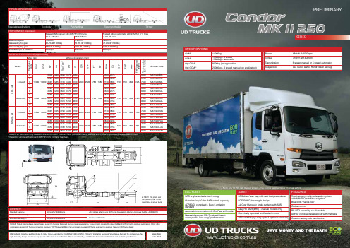
TYPICAL APPLICATIONSSERIESPERFORMANCE (Calculated)6 speed MLS manual with 235/75R 17.5 tyres4.111 diff ratio 4.555 diff ratio5 speed Allison automatic with 235/75R 17.5 tyres4.111 diff ratioMax road speed126km/h 114km/h126km/hGradeability 1st gear46.4% @ 11000kg 52.8% @ 11000kg41.0% @ 11000kgGradeability top gear 3.5%@ 11000kg 3.9% @ 11000kg 3.5%@ 11000kgEstimated rpm @ 100km/h2059rpm 2281rpm2059rpmGENERAL SPECIFICATIONS (Approximate)Mass (kg)Vehicle Dimensions (mm)VariantWheelbasecodeGVM*GCM**FA1RA1TotalTare1WBOLOWOH2FTRTROHCAGC2FHF2FHR2FHR2(loweredheight)Turningradius(kerbtokerb)UD order codeUD–leaf6 speedE110001550024001290369037706560220025261784168016202778190758844N/A6000MK11250E6LF23951280367542307230183032386700MK11250F6LK24451285373048308130213038387500MK11250K6LL24751290376551508670235041588000MK11250L6LN24951310380555009630296045088500MK11250N6LAutomaticE110001500023601270363037706560220025261784168016202778190758844N/A6000MK11250EALF23651260362542307230183032386700MK11250FALK24151270368548308130213038387500MK11250KALL24501270372051508670235041588000MK11250LALN24651295376055009630296045088500MK11250NALHAS2-air 6 speedF1100015500239013403730423072302200252617841680183032381907588007606700MK11250F6AK24451345379048308130213038387500MK11250K6AL24751350382551508670235041588000MK11250L6AN24951370386555009630296045088500MK11250N6AAutomaticF1100015000236513203685423072302200252617841680183032381907588007606700MK11250FAAK24151330374548308130213038387500MK11250KAAL24501330378051508670235041588000MK11250LAAN24651355382055009630296045088500MK11250NAAECO FLEETSCR engine emission technologyClass leading 50 litre AdBlue tank capacityADR80/03 compliant – Euro 5 emissionstandardAutomatic transmission with EcoFleet shift modeNewest Japanese MD-T cab with latestaerodynamic “low drag” performanceSAFETYSRS driver’s air bag with seat belt pretensionerECE-R29 Cab strength designAir Over Hydraulic brake system with ABSEasy Hill Start (EHS) – manual models onlyElectrically operated and heated mirrors360° visibility (by using up to 3 optional cameras)FEATUREST ouch screen multimedia audio systemwith NAVTEQ satellite navigationBluetooth “hands free”Cruise controlRE-PTO capability on all modelsADR42 compliant sleeper cab with mattressCustom factory cab paint option WARRANTYStandard warranty+36 months/150000 kms+ For details refer to your UD Trucks New Vehicle Warranty brochure Pub No. AUS000273Cab corrosion warranty+36 months/unlimited kms++ Covers selected items only. For details refer to your UD Trucks Extended Protection Plan brochurePub No. AUS000472Extended warranty++60 months/300000 kmsDISCLAIMER: Imported and distributed by Volvo Group Australia Pty Ltd (ABN: 27 000 761 259). Photos for illustration purposes. Volvo Group Australia Pty Ltd reserves theright to modify design and change equipment without previous notification. Please consult with your UD Dealer for the latest information about vehicle specifications.Issue dateJune 2012NOTES: *Rated GVM and axle capacities are subject to Federal, State and T erritory legal requirements. For automatic models, the rated GVM and GCM is for On Highway applications ONL Y, otherapplications require UD Trucks engineering approval. **OPT higher GCM on manual models requires UD Trucks engineering approval. See your UD Trucks dealer.SPECIFICATIONSGVM*11000kgGCM*15500kg – 6 speed15000kg – automaticOpt GVM*8000kg (on application)Opt GCM**20000kg – 6 speed manual (on application)Power180kW @ 2500rpmT orque716Nm @ 1400rpmTransmission 6 speed manual or 5 speed automaticSuspension UD Trucks leaf or Hendrickson air bagNote: MK 11 250 photo anddrawing shown, may not berepresentative of actual truckNote: MK 11 250 cab chassis shown - may not be representative of actual vehicleENGINEMakeUD Trucks ModelGH7TADescription 4 cycle, direct injection, diesel engine with overhead cam,4 valves per cylinder, water cooled and intercooler withturbocharging system.Cylinders6 in-lineT otal piston displacement 7013cc (7 litres)Bore x stroke 110mm x 123mmCompression ratio 17.5:1Max. Power (ECE Net)180kW (245ps) @ 2500rpm Max. Power (JIS Gross est.)187kW (254ps) @ 2500rpm Max. T orque (ECE Net)716Nm (528lb/ft) @ 1400rpm Max. T orque (JIS Gross est.)744Nm (548lb/ft) @ 1400rpm Max. governed engine speed2600rpmLubrication system Forced oil feed by gear pump, flat tube oil cooler, full flow and bi-pass oil filters with replaceable elements and 17 litre capacityCompressed air system Water cooled reciprocating type, single cylinder air compressor with air dryerCooling systemForced feed by centrifugal water pump, wax pellet type thermostat with bypass. Aluminium corrugated fin type radiator with cab front bonnet mounted reserve tank and a 600mm diameter 11 blade viscous coupling cooling fan.FUEL AND INTAKE SYSTEM Injection type Ultra high pressure common rail injection system Filtration Chassis mounted primary and engine mounted secondary Capacity 200 litre steel tank with lockable cap mounted on LHS chassisAir filtration Primary dry paper element air filter on RHS under cab Air intakeHigh mounted RHS air intakeEXHAUST AND EMISSION CONTROL Emission standard ADR80/03 (Euro 5 emission levels)Emission system Selective Catalytic Reduction (SCR)AdBlue capacity 50 litre polymer tank with lockable cap mounted on LHS Exhaust systemRHS chassis mounted muffler/catalytic converter with horizontal rear facing exhaust dischargeELECTRICAL Power24 volt, negative ground systemBattery capacity 2 x 12 volt 120Ah batteries mounted on LHS chassis (RHS chassis E wheelbase only)Alternator130 amp with built in IC regulatorCLUTCH (manual models only)Make UD TrucksDescription Dry single organic plate with push type diaphragm Disc diameter 350mmMechanismHydraulically operated with air assistanceTORQUE CONVERTER (automatic models only)Make Allison Model TC221Description One state, three element, polyphase. Includes standard integral damper with lock-up function Stall torque ratio1.73:1LOAD CAPACITY SUMMARY Front (kg)Rear (kg)HAS 200orLeaf Axle400076007600Steering/suspension 400090007600T yres400076007600Max. ground capacity*400076007600BRAKES T ype WABCO Anti-lock Braking System (ABS)Description Air Over Hydraulic (AOH), dual line system, with aluminium air tanks, drum brakes, 4 channel ABS and Easy Hill Start (EHS – manual models only)Air pressure 7.2-8.5kg/cm 2Front Rear T otalDrum diameter 320mm 320mm Lining area 1360cm 21672cm 23032cm 2Park brake Hand operated pneumatically controlled spring park brake on drive axleAuxiliary brake Butterfly type exhaust brakeSTEERINGT ypeRecirculating ball and screw with hydraulic assist Steering gear ratio 18.8:1Column Adjustable, tilt and telescopic controlSteering wheel 460mm diameter with ignition key steering lockWHEELS AND TYRES Wheels Pressed steel disc type 6.75in x 17.5in rim with 131mm offset – 10TCS, 6 stud (222.25mm PCD)Front tyres Single 235/75R 17.5 Dunlop SP341, regroovable Rear tyresDual 235/75R 17.5 Dunlop SP442, regroovable (E & F wheelbase only)Dual 235/75R 17.5 Dunlop SP341, regroovable (except E & F wheelbase)Spare tyre Single 235/75R 17.5 Dunlop SP341, regroovable, mounted on spare tyre carrier (STC) at rear of chassisFRAME Construction Ladder, channel type double skin chassis construction Width860mmSide rail dimensions 234mm x 70mm x 7mm (except N wheelbase) 234mm x 80mm x 7mm (N wheelbase only)Material Pressed high tensile carbon steel Rail dataT ensile Yield Modulus55kg/mm 248kg/mm 2Refer to Body Manual.auSTANDARD DRIVER AIDS Safety equipmentSRS driver’s steering wheel air bag SRS driver’s seat belt pretensioner ECE-R29 cab crash design ABS – Anti-lock Brake SystemEasy Hill Start (EHS) – manual models onlyInstrumentationFully electronic, CAN-BUS instrument system including speedometer, tachometer (with economical green driving band), fuel, temperature, AdBlue level and independent front and rear air circuit pressure gauges.Digital odometer display with dual trip function.Warning systems Up to 22 visual warning lamps plus up to 38 different written warnings displayed on the LCD screen. In conjunction, 13 audible tones are usedDriver assistanceA Driver’s Information System (DIS) displaying useful vehicle data including: Date/time, engine temperature, oil pressure, voltmeter, trip information, along with service intervals f or e ngine, t ransmission, d ifferentials, b elts a nd a ir filter. Electronic stalk mounted cruise control. GPS satellite navigation with NAVTEQ “truck” mappingEXTERNAL CABIN DescriptionAerodynamically designed, forward control, pressed steel construction cab with 45° torsion bar cab tiltMounting type Spring suspended cab with 2 dual acting shock absorbers Crash test standard Designed to ECE-R29Cab paint Standard – Jumping White (W33)Doors90° opening, steel construction with side intrusion beams Inspection pointsAll daily inspections can be carried out without lifting the cab from the front opening inspection panel Bumper type 1 piece, pressed steel, air dam front bumperMirrorsHeated and electrically operated LH and RH main mirrors with wide vision spot mirrors and passenger side down facing spot mirrorLamps Halogen multi-reflector head lamps ADR49/00 bumper mounted fog lamps ADR49/00 roof mounted clearance lights GlassTinted front, side and rearWipersDouble arm, 2 speed wipers with intermittent operation and integrated washersReversing system Rear facing reverse light and audible warning alarm Optional – remote mounted camera with microphone (see Dealer Options list)INTERNAL CABIN LightingSingle ON/OFF/DOOR interior light with an independent 720mm x 140mm fluorescent lampStandard seat capacity 3 occupant seats – 2 outer seats with retractable 3 point ELR seat belts, centre seat with adjustable lap belt Driver’s seat CVG multi-adjustable, air suspended with automatic height control and 7 position adjustable shock absorber Passenger seat(s)Flat folding LH assistant seat with lift-up base Flat folding centre seat with back of seat storage Sleeping capabilityADR42/04 compliant sleeper bunk with mattress (suitable for stationary sleeping). Sleeper bunk cab curtain rails with curtainsSide windows Power operated door glass SecurityRemote keyless central lockingAir conditioning Adjustable temperature control with multi-speed fan Audio system Double DIN sized, AM/FM/CD 4.8" T ouch screen multimedia system with USB, SD card and Bluetooth capabilityCup holders 2 centre mounted cup-holdersRH and LH door mounted bottle-holders Additional 2 back of centre seat cup-holdersStorageDriver and passenger overhead consoles (6 litres each) with lids10 litre back of centre seat storage box with lid Driver and passenger door pockets Power outlet24 volt 240W cigarette lighter/power outlet DIN accessory fitment T wo DIN sized compartments for accessory fitment Floor coveringVinylFACTORY OPTIONAL EQUIPMENT (Indent order)SuspensionFront stabiliser barLong taper leaf front springs 294Nm/mm (29.9kg/mm) – 3600kg maximum ground capacity*SeatingLarge centre console (replaces centre seat)Engine/PTO controlElectronic engine governor control with external control leverTransmission PTO High torque transmission PTO – 343Nm @ 100% engine speed output – manual models onlyCab paint20 x factory option coloursCustom paint colours (up to 3 colours per cab)DEALER FIT OPTIONAL EQUIPMENT RatingsOptional GVM 8000kg* – for Light Rigid truck licence Optional GCM 20000kg* – manual models only Rear engine PTO 343Nm torque capacity @ 120% engine speed 343Nm torque capacity @ 85% engine speed PTOTransmissionFleet management GPS-based fleet management systemCameras Up to 3 cameras connected to the in-dash multimedia systemOtherRefer to your UD Trucks Accessories brochure.auTRANSMISSION 6 SPEED MANUAL Make UD Trucks Model MLS63BDescription Six forward speeds and one reverse, synchromesh 2nd to 6th gears. Non-synchro 1st and reverse Shift type Mechanically operated shift with air servo assist Gear ratios1st 6.724th 1.44Rev 6.122nd 4.035th 1.003rd2.306th0.74PTO capability LHS 147Nm @ 62% engine speed (nominal ratio)5 SPEED AUTOMATIC Make Allison Model LCT2500Description Five forward speeds and one reverse. Fully automatic Allison Gen4 adaptive shift with Power and EcoFleet modesShift type T -bar shifter with shift lock and overdrive buttons, cable operation Gear ratios1st 3.514th 1.00Rev 5.092nd 1.905th0.743rd1.44PTO capabilityTransmission type drive with LHS and RHS openings 339Nm using one opening, or 542Nm total using both openingsFRONT AXLE AND SUSPENSION SYSTEM Axle makeUD TrucksDescription Drop forged steel “I” section beam, reverse “ELLIOT” type Suspension Multi-leaf spring with anchor at front and shackle at rear Dimensions (mm)70mm x 1300mm Number of leaves 8Spring constant 244N/mm (24.9kg/mm)Shock absorbers 2 telescopic double actingMax. ground capacityRefer to the Load Capacity Summary on Page 3REAR AXLE AND SUSPENSION SYSTEM Axle make UD TrucksT ype Fully floating pressed steel banjo type housing with single driveGear typeSingle reduction, hypoid gearFinal reduction ratio 6 speed manual – 4.111:1 (F-N) 4.555:1 (E)5 speed automatic – 4.111:1LEAF SUSPENSION DescriptionSemi-elliptic leaf spring and helper with anchor at front and shackle at rear Leaf dimensions (mm)Main: 70mm x 1300mm Helper: 70mm x 980mm Number of leaves Main: 7 Helper: 7Spring constant (total)985N/mm (100.4kg/mm)Shock absorbers 2 telescopic double actingMax. ground capacityRefer to the Load Capacity Summary on Page 3AIR SUSPENSION Description Hendrickson HAS200Air spring diameter 270mm Number of springs 2 air bagsSpring constant118N/mm (12.0kg/mm)Shock absorbers 2 telescopic double actingMax. ground capacityRefer to the Load Capacity Summary on Page 3SHIFT RANGE。
Rebel Chameleon 125XBRi系列LED多状态指示灯(NEMA 4X封装)说明书

Installation Instructions for Rebel Chameleon TM 125XBRi Series LED Multi-Status Indicator inNEMA 4X EnclosuresDescriptionThe 125XBRi Series Chameleon Multi-Status LED Indicator is a UL and cUL listed, multi-color LED signaling appliance in a NEMA 4X rated enclosure. The indicator can be panel or conduit mounted. A protective guard, Cat. No. 125GRD, is also available.The lights are available in 24V DC and 120V 50/60 Hz. They are available in either Red/Blue/Amber or Red/Green/Amber. Edwards Signaling's NEW 125XBRi Multi-status Indicator is more "chameleon-like" than ever. With our new adaptive design - one device does it all. With a quick change to the new 125 Chameleon's dip switch settings, these flexible multi-status indicators instantly adapt for use with or without control from an external PLC, PAC, or control relay. Now, regardless of the application you will have just the right device for the job with only half the inventory.XTRA-SAFE EnabledThe Chameleon 125XBRi devices ship as standard with Edwards Signaling's XTRA-SAFE TM Technology (patent pending) Enabled. XTRA-SAFE multi-status indicating devices employ patented combinations of color AND flash-rate to provide more definite status indication to those who are color-blind. With XTRA-SAFE, when Chameleon multi-status indicators are turned red, they pulse at a rate of 240 flashes per minute, further emphasizing the urgency which the color red typically connotes. When amber, these devices pulse at a "less urgent" rate of 120 flashes per minute. When Chameleon multi-status indicators are turned blue or green and no other colors are energized, the Chameleon devices remain "steady-on" and do not flash. Even in extreme cases where no color is perceived, flash-rate variation provides a redundant layer of visual indication.When XTRA-SAFE Technology is enabled, and multiple col-ors are energized, the device will cycle through the energized colors at the following pre-set flash-rates:Red: 240 FPM Amber: 120 FPM Green or Blue: 65 FPMXTRA-SAFE DisabledWhile in most cases, the added layer of safety gained by op-erating a multi-status indicator with XTRA-SAFE Technology is desirable, some applications may not require differentiation in flash rates. In other applications, changes do not corre-spond to escalating levels of urgency. The adaptive design of the new Chameleon 125 XBRi allows the product to be adapted to accommodate these requirements by configuring the dipswitches as shown in Figure 1 (Applications WITH-OUT a separate PLC or Controller - XTRA-SAFE Technology Disabled). With XTRA-SAFE Disabled, when red or amber,P/N 3101611 ISSUE 3© 2010 Phone: (800) 336-4206 Fax: (800) 454-2363the unit pulses at a rate of 65 flashes per minute. When Chameleon multi-status indicators are turned green or blue and no other colors are energized, the Chameleon devices remain "steady on" and do not flash.When XTRA-SAFE Technology is disabled, and multiple col-ors are energized, the device will cycle through all energized colors at 65 FPM.Externally ControlledThe Chameleon multi-status indicators can also be used in applications where they will be controlled "externally" using a Programmable Logic Controller (PLC) or other such external controller. When externally controlled by a PLC, activation of colors and flash-rate are fully customizable, and can be programmatically determined. In applications, where multiple colors are activated simultaneously, the lights operate on a priority with red highest, amber second and blue or green, the lowest. Refer to Figure 1 (Applications WITH a separate PLC or Controller).Wire color corresponds with each indicated color.Red wire = Red LED's Yellow wire = Amber LED'sBlue with Green tracer wire = Green or Blue LED'sElectrical SpecificationsGRAY BASE BLACK BASE Catalog NumberCatalog NumberElectrical SpecsRed, Green, Amber125XBRiRGA24D 125XBRiRGA24DB 24V DC, 0.150A 125XBRiRGA120A125XBRiRGA120AB120V AC*, 0.100ARed, Blue, Amber125XBRiRBA24D 125XBRiRBA24DB 24V DC, 0.150A 125XBRiRBA120A125XBRiRBA120B120V AC*, 0.100A* 120V AC 50/60 HzMechanical SpecificationsOutdoor LocationsTemperature Ratings ...........-31F to +150F (-35C to +66C)P/N 3101611 ISSUE 3Installation-Applications with a separate PLC or Controller - Set dipswitches SW1 and SW2 to the OFF position.Table 2. PLC CompatibilityGRAY BASE BLACK BASE Catalog Number Catalog Number Operating Voltage (Volts)Max. off state leak-age current (mA)Continuous on current (mA)Surge (inrush/duration)(A/μSeconds)125XBRiRGA24D 125XBRiRGA24DB 24V DC515028.5/65125XBRiRBA24D 125XBRiRBA24DB 125XBRiRGA120A 125XBRiRGA120AB 120V AC 50/60 Hz510028.5/212125XBRiRBA120A 125XBRiRBA120BTo avoid risk of injury, install lens before energizing the unit and do not remove orinsert light source when unit is energized.WARNING1. Remove (4) screws securing the lens to the base frombottom of base (Figure 2) and remove lens.- Applications without a separate PLC or Controller- XTRA-SAFE Technology Disabled: Set dipswitch SW1 to the OFF position and SW2 to the ON position.WARNINGTo prevent electrical shock, ensure that poweris turned off before installing the signal.The 125XBRi Multi-Status indicator is shipped with XTRA-SAFE Technology Enabled. The unit offers two other field selectable options: (1) for applications without a separate PLC or controller with the XTRA-SAFE Technology disabled or (2) for applications with a separate PLC or controller. For more information on the features, refer to the description.For settings, refer to Figure 1.XTRA-SAFE EnabledXTRA-SAFE DisabledWith a PLC or other External Controller2. Replace lens on base and secure with (4) screwsremoved in step 1.Figure 1. Dipswitch SettingsFigure 2. Removing the LensP/N 3101611 ISSUE 3WARNINGTo avoid risk of injury, install lens beforeenergizing the unit.WARNINGTo prevent electrical shock, disconnect powerbefore removing the lens.1. Thread the 18" (457 mm) signal wire leads through either1/2" or 3/4" conduit into an approved conduit outlet box. (Product is supplied with a double threaded - 1/2" internal and 3/4" external - conduit hub.)2. Thread the conduit onto the base of the signal.Conduit Mounting (Figure 3)Panel Mounting (Figure 4)Note: When panel mounting these beacons, the surfaceand construction details of the panel must betaken into consideration in order to ensure that the integrity of the outdoor, NEMA 4X rating is fully maintained. Installer should evaluate.1. Place the mounting gasket (supplied) over the hole inthe panel and route the signal wires through the gasket and the hole in the panel.2. Insert the base through the hole in the panel and screwthe locking nut (supplied), with the raised locking edge facing the mounting surface, onto the base to secure the beacon.Figure 4. Panel MountingWiring (Refer to Figures 3 and 4)AC models1. There are four 18" wire leads: white (neutral), red(for activation of red LEDs), blue with green stripe (for activation or green or blue LEDs--depending on model) and amber (for activation of amber LEDs).Using wire nuts, connect white lead to AC neutral and connect each of the other three leads to AC hots.DC models1. There are four 18" wire leads: black (negative), red(for activation of red LEDs), blue with green stripe (for activation of green or blue LEDs--depending on model) and amber (for activation of amber LEDs).Using wire nuts, connect black lead to DC negative and connect each of the other three leads to DC positives.2. Turn on power and verify that the signal operatesproperly.MaintenanceCleaningThe module lens exterior surfaces should be periodically cleaned with a soft clean cloth using water and a mild deter-gent to maintain optimum light visibility. Disconnect power before cleaning.Lens Replacement1. Remove (4) screws securing the lens to the base frombottom of base and remove lens.2. Replace lens on base and secure with (4) screwsremoved in step 1 (Figure 2).Table 3. Replacement PartsGRAY BASE BLACK BASECatalog Number Catalog Number Replacement Lens Replacement Lamp125XBRiRBA24D125XBRiRBA24DB125LC The 148,000 hour** lamp ispermanently installed.125XBRiRGA24D125XBRiRGA24DB125XBRiRBA120A125XBRiRBA120AB125LC The 148,000 hour** lamp is permanently installed.125XBRiRGA120A125XBRiRGA120AB*Median LED Life (L70) based on manufacturer's projections. Refer to /pdfs/WP15.pdf.P/N 3101611 ISSUE 3。
- 1、下载文档前请自行甄别文档内容的完整性,平台不提供额外的编辑、内容补充、找答案等附加服务。
- 2、"仅部分预览"的文档,不可在线预览部分如存在完整性等问题,可反馈申请退款(可完整预览的文档不适用该条件!)。
- 3、如文档侵犯您的权益,请联系客服反馈,我们会尽快为您处理(人工客服工作时间:9:00-18:30)。
0
Recommended Operating Conditions
Parameter Ambient Operating Temperature Supply Voltage OPT-1250x1xx OPT-1250x2xx, OPT-1250x4xx Note: See ordering information for detail Symbol TA VCC Min. 0 4.75 3.135 Typ. Max. 70 5.25 3.465 Unit ºC V Note 1
(At recommended ambient operating temperature, TA and supply voltage, VCC; Data Rate=1.25Gb/sec, PRBS=27-1 NRZ, 62.5/125um MMF) Parameter Transmitter Output Optical Power (Avg.) Optical Extinction Ratio Center Wavelength Spectral Width (RMS) Optical Rise/Fall time Relative Intensity Noise Output Eye Receiver Sensitivity (Avg.) Input Optical Wavelength Signal Detect-Asserted (Avg.) Signal Detect-De-asserted (Avg.) Signal Detect-Hysteresis Receiver saturation power Notes: 8. These are 20%~80% values 9. The sensitivity is provided at a BER of 1×10⁻¹⁰ or better with an input signal consisting of 1250Mb/s, 27-1 PRBS. PIN 850 PA PD PA-PD PSAT -17 -30 0.5 -4 -17 dBm nm dBm dBm dB dBm 2 dBm dB 850 860 nm C 0.85 nm 0.26 ns 1 tr/tf RIN -117 dB/Hz Complies with the IEEE 802.3z/D2 specification, and is class 1 laser eye safety PO ER -9.5 9 830 -4 Symbol Min. Typ. Max. Unit Note
1
DELTA ELECTRONICS, INC.
Sep., 2006 Rev. 0G
元器件交易网
OPT-1250xxxx Series
Absolute Maximum Ratings
Parameter Storage Temperature Lead Soldering Temperature Lead Soldering Time Supply Voltage Symbol Ts TSOLD tSOLD VCC Min. -40 Typ. Max. 85 260 10 6 Unit ºC ºC sec. V Note
OPT-1250B4Q2x) (At recommended ambient operating temperature, TA and supply voltage, VCC; Data Rate=1.25Gb/sec, PRBS=27-1 NRZ, 9/125um SMF) Parameter Transmitter Output Optical Power (Avg.) OPT-1250BxIx OPT-1250BxQx Optical Extinction Ratio Center Wavelength Spectral Width (RMS) Optical Rise/Fall time Relative Intensity Noise Output Eye Receiver Sensitivity (Avg.) Input Optical Wavelength Signal Detect-Asserted (Avg.) Signal Detect-De-asserted (Avg.) Signal Detect-Hysteresis Receiver saturation power Notes: 6. These are 20%~80% values 7. The sensitivity is provided at a BER of 1×10⁻¹⁰ or better with an input signal consisting of 1250Mb/s, 27-1 PRBS. PIN 1310 PA PD PA-PD PSAT -19 -35 0.5 -3 -19 dBm nm dBm dBm dB dBm 2 PO ER -12 -9.5 9 1270 -3 -3 1310 dBm Symbol Min. Typ. Max. Unit Note
元器件交易网
OPT-1250xxxx Series RoHS Compliant 1X9 SC Duplex Receptacle Transceiver Module for Gigabit Ethernet
Features
Industry Standard 1 x 9 Footprint and duplex SC Connector interface Compliant with Specifications for IEEE 802.3z Gigabit Ethernet OPT-1250Bxxx compliant with the 1.0625GBd Fibre Channel 100-SM-LC-L FC-PI Rev.13 OPT-1250Axxx compliant with the 1.0625GBd Fibre Channel FC-PI 100-M5-SN-I Rev.13 Single +3.3V or 5V Power Supply PECL or TTL Receiver Signal Detect Indicator Wave Solderable and Aqueous Washable Laser Class 1 Product which comply with the requirements of IEC 60825-1 and IEC 60825-2
dB 1355 nm 2.8 nm 0.26 ns 1 tr/tf RIN -120 dB/Hz Complies with the IEEE 802.3z/D2 specification, and is class 1 laser eye safety
C
Mask of the eye diagram for the optical transmit signal
OPT-1250B2I1x:
1310nm FP laser, Data Link up to 5km in 9/125um SMF
OPT-1250BxQxx:
1310nm FP laser, Data Link up to 10km in 9/125um SMF 1310nm FP laser, up to 550m in 50/125 m MMF 1310nm FP laser, up to 550m in 62.5/125 m MMF
Electrical Characteristics
(At recommended ambient operating temperature, TA and supply voltage, VCC) Parameter Total Supply Current Transmitter Transmitter Data Input Voltage-Low Transmitter Data Input Voltage-High Transmitter Differential Input Voltage Receiver Data Output Voltage-Low Data Output Voltage-High Receiver Differential Output Voltage Output Data Rise/Fall Time PECL SD Output LOW level output voltage HIGH level output voltage TTL SD Output LOW level output voltage HIGH level output voltage Symbol ICCT VIL-VCC VIH-VCC VDT VOL-VCC VOH-VCC VDR tr/tf VSDH-VCC VSDL-VCC VSDH VSDL Min. Typ. Max. 300 -1.475 -0.880 1.6 -1.62 -0.74 1.2 0.4 -1.60 -0.9 VCC 0.8 Unit mA V V V V V V ns V Note
-1.810 -1.165 0.3 -1.95 -1.045 0.5
1 1 2 1 1 2 3 4
0.7
-1.84 -1.1 2 0
V
5
Notes: 1. For OPT-1250A1F1x, OPT-1250A4F1x, OPT-1250B2I1x, OPT-1250B2Q1x and OPT-1250B1Q1x. 2. For OPT-1250A2F2x and OPT-1250B4Q2x. 3. These are 20%~80% values 4. For OPT-1250A1F1x, OPT-1250A2F2x, OPT-1250B2I1x, OPT-1250B1Q1x and OPT-1250B2Q1x 5. For OPT-1250A4F1x and OPT-1250B4Q2x