VMwareNS网络虚拟化
VMware网络虚拟化产品NSX安装配置指南
NSX for vSphere Getting Started GuideVMware NSX for vSphere, release 6.0.xJuly 21, 2014Table of ContentsNSX for vSphere Getting Started Guide (1)Introduction (3)Installation of NSX for vSphere (4)Infrastructure requirements for NSX-v (4)NSX-v Installation overview (6)Step 1: Install NSX Manager (6)Step 2: Install the NSX Controller Cluster (8)Step 3: Prepare ESXi hosts for NSX (10)L2 Logical Switching (14)Goal of the L2 logical switching lab (14)Create four Logical Switches (14)Add VMs on Web/App/DB Logical Switches (15)Validate that VMs on the same Logical Switch can communicate (16)Distributed Logical Routing (18)Goal of the logical routing lab (18)Create a single Distributed Logical Router (18)Validate that VMs in the different Logical Switches can communicate (21)Distributed Firewalling (23)Goal of the Distributed Firewalling lab (23)Create the Distributed Firewall rules (23)Validate the Distributed Firewall rules (25)Logical Centralized Routing (26)Goal of the Logical Centralized Routing lab (26)Create a single Logical Centralized Router (Edge) (27)Configure Dynamic Routing on Logical Distributed and Centralized Routers (29)Validate that dynamic routes are being learned (32)Validate communication from internal to Centralized Router external interface (33)Create many-to-one NAT (for traffic initiated from Web-Tier01 to external) (33)Validate communication from Web-Tier-01 to Internet (34)Logical Load Balancing (35)Goal of the Logical Load Balancing lab (35)Create one new Load Balancer (36)Configure the Load Balancer (37)Update the Distributed Firewall rules to allow Load Balancer-to-Web server communication (40)Validate that the Server Pool is UP (40)Create a one-to-one NAT rule on the External Edge Router (for traffic initiated from external to loadbalancer) (41)Check that external network hosts can communicate to VIP (42)Getting Help and More Information (43)NSX-v Documentation (43)Contacting the NSX Technical Services Team (43)NOTE: To obtain the latest information about NSX for vSphere, please visit/products/nsxIntroductionThis document provides step-by-step examples that demonstrate how to set up the following network services in NSX for vSphere:∙Logical Switches∙Logical Distributed Routers∙Distributed Firewalls∙Logical Centralized Routers (Edge)∙with Dynamic Routing∙with many-to-one NAT∙Logical Load Balancers (Edge)At the end, you’ll have the following logical network deployed in your lab:Figure 1 – Logical View of labL2 bridging, VPN, and service composer are not covered in this document. Likewise, integrations with third party vendors, such as Palo Alto Networks, Symantec and F5, are not covered here.Installation of NSX for vSphereThis section guides you through the step-by-step installation, configuration and validation of a new NSX for vSph ere (“NSX-v”) deployment.Infrastructure requirements for NSX-vVMware elements:Prior to installing NSX for vSphere, you must deploy:∙vCenter 5.5 with:∙one or more Compute clusters∙Management and Edge cluster∙two or more ESXi 5.5 in each clusterEach ESXi host has the following characteristics:∙Server hardware is listed on the VMware HCL for vSphere 5.5∙2x Quad Core x86_64 compatible CPUs with a speed of 2Ghz or greater, plus hardware-assisted virtualization support (total of 8 physical cores)∙32GB of RAM or greater∙2x Physical NICs∙Either 5GB of Local Disk/Dedicated boot from SAN LUN or supported ESXi embedded device (USB/SD). Local Disk is not required if vSphere Auto Deploy is used.Figure 2 – Infrastructure for NSXFor resource constraints, this lab uses only one Compute Cluster, as shown in the following screenshots.Network fabric:Configure at least 1600 byte of MTU frame sizes on all the physical switches/routers between ESXi.vCenter:Clusters:∙One Compute Cluster “Cluster-CompA” with two ESXi.∙One Mana gement + Edge Cluster “Cluster-Mgt_Edge” with two ESXi.Figure 3 – vCenter Host ViewNetworking:∙Virtual Standard Switch (vSS) for Cluster-CompA and Cluster-Mgt_Edge:∙Management: This vSS is used for the ESXi-Compute and ESXi-Mgt_Edge management.Interface to use: The interface of the ESXi in Cluster-CompA + Cluster-Mgt_Edge on theManagement network is used.∙Virtual Distributed Switch (vDS) for Cluster-CompA:∙vDS-CompA: This vDS will be used for the VM production traffic. Interface to use: The interface of the ESXi in Cluster-CompA on the Transport network is used. Note: No ESXi IP@ isconfigured yet.∙Virtual Distributed Switch (vDS) for Cluster-Mgt_Edge:∙vDS-Mgt_Edge: This vDS will be used for the VM production traffic. Interface to use: The interface of the ESXi in Cluster-Mgt_Edge on the Transport network is used. Note: No ESXi IP@ is configured yet. Note2: Create a Management Network for the future logical routers“LogicalRouter_Mgt”∙vDS-External: This vDS will be used to talk to the physical external network. Interface to use: The interface of the ESXi in Cluster-Mgt_Edge on the External network is used. Note: No ESXi IP@ is configured.Figure 4 – vCenter Networking ViewNSX-v Installation overviewIn this step, you’ll deploy the NSX Manager and NSX Controller Nodes:Figure 5 – NSX elementsStep 1: Install NSX ManagerThe NSX Manager is the centralized management component of NSX, and runs as a virtual appliance on an ESX host.1.Install NSX Manager: From vCenter Home-> Hosts and Clusters, select Cluster-Mgt_Edge andDeploy OVF TemplateFigure 6 – Installation NSX Manager2.Register NSX Manager with vCenter: Log in NSX Manager and from NSX Manager Manage ->NSX Management Services, register to vCenterFigure 7 – NSX Manager registration to vCenter3.Validate registration: Log out of vCenter if already logged in. And re-log in with root (required toget the NSX plugin installed in vCenter). Note: The first login can take a few minutes. After registration, you will see the Network & Security plugin in the Inventory:Figure 8 – NSX plugin in vCenterStep 2: Install the NSX Controller ClusterThe NSX Controller Cluster is a distributed state management system that controls virtual networks and overlay transport tunnels1.Install the first NSX Controller Node: From NSX Home -> Installation, add first NSX ControllerNode.Figure 9 – First NSX Controller Node installationThe IP Pool “NSX Controller Cluster” has been created with the following settings:Figure 10 – NSX Controller Cluster IP pool2.Validate the installation of first NSX Controller Node: The deployment of an NSX ControllerNode can take few minutes.Figure 11 – First NSX Controller Node deployedNote: In rare cases, the Controller takes too long install and is automatically deleted. In such cases, you can install a DHCP server in the Controller’s subnet to speed up its installation. That DHCP server can be configured with fake IP addresses since the Controller will still get its IP address from the NSX IP Pool.3.Install the second and third NSX Controller Nodes:Note: You can run with only one NSX Controller in a lab (not supported in a production setting), but this will render you unable to test Controller Node high-availability. For a productiondeployment or to test high-availability, you must install a total of three Controller Nodes.From NSX Home -> Installation, add second and third NSX Controller NodesFigure 12 – Second and third NSX Controller Nodes installation4.Validate installation of all three NSX Controller NodesFigure 13 –NSX Controller Cluster deployedStep 3: Prepare ESXi hosts for NSXTo provide all the NSX services, special kernel modules and user space tools have to be installed on the ESXi hosts.1.Install NSX elements on cluster hosts: From NSX Home -> Installation-> Host Preparation,click Install for all the clusters:Figure 14 –Installation of NSX elements on cluster hosts2.Check the installation of NSX elements on cluster hostsFigure 15 – Validation of installation of NSX elements on clusters hosts3.Configure the VXLAN VTEP interface for Cluster-CompA hosts: From NSX Home ->Installation-> Host Preparation, click Configure for the Cluster-CompA:Figure 16 – Configuration of VTEP interface for Cluster-CompA hostsFigure 17 – Configuration of VTEP IP@ pool for the Cluster-CompA hosts4.Validate the VTEP configuration on the Cluster-CompA hosts. Note: You may see an “ErrorUncon figure” message. This is a known display issue. Refresh the window to see the correct status.Figure 18 – Validation VTEP IP@ configuration for the Cluster-CompA hosts5.Configure the VXLAN VTEP interface for Cluster-Mgt_Edge hosts:Figure 19 – Configuration of VTEP interface for Cluster-Mgt_Edge hostsFigure 20 – Configuration of VTEP IP@ pool for the Cluster-Mgt_Edge hosts6.Validate the VTEP configuration on the Cluster-Mgt_Edge hosts. Note: You may see an “ErrorUnconfigure” message. This is a known display issue. Refresh the window to see the correct status.Figure 21 – Validation VTEP IP@ configuration for the Cluster-Mgt_Edge hosts7.View of the VTEP IP@ allocated to each Cluster hosts. From NSX Home -> Installation->Logical Network Preparation -> VXLAN Transport:Figure 22 – View of the VTEP IP@ allocated to each Cluster hosts8.Configure VXLAN Segment ID (VXLAN Network Identifier – VNI): From NSX Home ->Installation-> Logical Network Preparation -> Segment ID, click Edit. Note: Since NSX 6.0 with ESXi 5.5, multicast support is no longer required on the physical fabric.Figure 23 – View of the VTEP IP@ allocated to each Cluster hosts9.Configure a Transport Zone: The transport zone is the compute diameter of your cloud. You wantall your ESXi hosts to participate to your cloud. From NSX Home -> Installation-> LogicalNetwork Preparation -> Transport Zone, click +. Note: Since NSX 6.0 with ESXi 5.5, multicastsupport is no longer required on the physical fabric.Figure 24 – Creation of the Transport Zone that spans among all ClustersThis completes the installation of the NSX-v elements of your deployment. Proceed to the logical switch set-up steps in the next section.L2 Logical SwitchingGoal of the L2 logical switching labIn this section, you will create Logical Switches.Figure 25 – Logical View Logical SwitchesCreate four Logical SwitchesFrom NSX Home -> Logical Switches, create four Logical Switches called: ∙Transit-Network-01∙Web-Tier-01∙App-Tier-01∙DB-Tier-01Figure 26 –Logical Switch creationNote: You will notice that one vDS Port Group is automatically created for each Logical Switch. From vCenter Home -> NetworkingFigure 27 –vDS Port Groups created for each logical switchAdd VMs on Web/App/DB Logical SwitchesYou have VMs on the different Cluster-CompA hosts:Figure 28 – VMs in Cluste-CompAFrom NSX Home -> Logical Switches, add VMs to the appropriate logical switchFigure 29 – Add VMs onLlogical SwitchFigure 30 – Select VMsNote: You can check the VMs are connected to the correct Logical Switch on vCenter too: From vCenter Home -> Hosts and Clusters, look at the VM HardwareFigure 31 – Validate VM Network adapter is connected to vDS port groupValidate that VMs on the same Logical Switch can communicateFigure 32 – ping between Web VMsNote: The VM traffic flow in the fabric is:Figure 33 – Logical Switch traffic flowDistributed Logical RoutingGoal of the logical routing labIn this step, you’ll create a Distributed Logical Router.Figure 34 – Logical View Distributed Logical RouterCreate a single Distributed Logical RouterFrom NSX Home -> NSX Edges, create a Distributed Logical Router with four interfaces (LIFS) ∙Uplink to Transit-Network-01 with an IP of 172.16.1.2/29∙Internal connected to Web-Tier-01 Logical Switch with IP 10.0.1.1/24∙Internal connected to App-Tier-01 Logical Switch with IP 10.0.2.1/24∙Internal connected to DB-Tier-01 Logical Switch with IP 10.0.3.1/24Figure 35 – Logical Distributed Router creation, first paneFigure 36 – Logical Distributed Router creation, second paneFigure 37 – Logical Distributed Router creation, third paneNote: One Management Interface must be configured. This interface is to access the Logical Router Control VM via SSH for management/troubleshooting (t he VM production traffic doesn’t reac h the Logical Router Control VM - see Figure 39 and Figure 40). For SSH access, configure a management IP address (not shown in the screenshot above).Validate that VMs in the different Logical Switches can communicateFigure 38 – ping between Web and App VMNote: The Logical Router Control VM (in the Mgt_Edge Cluster) is not involved in the L3 VM traffic flow.The VM traffic flow in the fabric is shown below.Figure 39 – L3 traffic flow – case both VMs are in the same ESXi hostFigure 40 – L3 traffic flow – case both VMs are in different ESXi hostsDistributed FirewallingGoal of the Distributed Firewalling labIn this step, you’ll create the Distributed Firewall rules.Figure 41 – Logical View Distributed FirewallCreate the Distributed Firewall rulesFor ease of use, the example below is using Logical Switch Names for the “Source” and “Destination” instead of subnets.This option works only if you have the VM Tools installed on the VMs.If you do not have the VM Tools on your VMs, use subnet.From NSX Home -> Firewall, create the rules:1)External access: Source any, Destination Web-Tier-01, Allow https, Apply To Web-Tier-012)Inter Web-Tier-01: Source Web-Tier-01, Destination Web-Tier-01, Allow icmp + ssh + http, ApplyTo Web-Tier-013)Inter Web-Tier-01_block: Source Web-Tier-01, Destination Web-Tier-01, Block any, Apply To Web-Tier-014)Web-Tier-01-App-Tier-01: Source Web-Tier-01, Destination App-Tier-01, Allow icmp + http, ApplyTo Web-Tier-01 + App-Tier-015)Inter App-Tier-01: Source App-Tier-01, Destination App-Tier-01, Allow icmp + ssh + http, Apply ToApp-Tier-016)App-Tier-01-DB-Tier-01: Source App-Tier-01, Destination DB-Tier-01, Allow icmp + mysql, ApplyTo App-Tier-01 + DB-Tier-017)Web-Tier-01-External: Source Web-Tier-01, Destination any, Allow all, Apply To Web-Tier-018)Everything else: Source any, Destination any, Block any, Apply To Web-Tier-01 + App-Tier-01 +DB-Tier-01Note: To display the field “Apply To”, click on the grid:Figure 42 –Distributed Firewall fields selectionFigure 43 –Distributed Firewall rulesValidate the Distributed Firewall rulesFigure 44 – ping and ssh between Web and App VM Note: The non-authorized traffic is dropped at the beginning:Figure 45 – Distributed Firewall traffic flowLogical Centralized RoutingGoal of the Logical Centralized Routing labIn this step, you’ll create a Logical Centralized Router (Edge) with:∙dynamic routing∙many-to-one NATFigure 46 – Logical View Logical Centralized RouterCreate a single Logical Centralized Router (Edge)From NSX Home -> NSX Edges, create an Edge Service Gateway with two interfaces (LIFS) ∙Uplink to External with an IP of 20.20.20.2/24∙Internal to Transit-Network-01 with an IP of 172.16.1.1/29Figure 47 – Logical Centralized Router creation, first paneFigure 48 – Logical Centralized Router creation, third paneFigure 49 – Logical Centralized Router creation, fourth paneFigure 50 – Logical Centralized Router creation, fifth paneFigure 51 – Logical Centralized Router creation, sixth paneConfigure Dynamic Routing on Logical Distributed and Centralized RoutersDynamic routing configuration on Logical Distributed Router1)Enable Dynamic Routing:a)From NSX Home -> NSX Edges, select the Logical Distributed Router and navigate to Manage ->Routing -> Global Configuration, and click Edit Dynamic Routing Configuration.b)Accept the default Router ID and Publish change (don’t click “Enable OSPF” here because aProtocol Address needs to be defined first)Figure 52 – Logical Distributed Router Dynamic Routing configuration2)Enable OSPFa)Navigate to Manage -> Routing -> OSPF, click Edit:o Enable OSPF checkboxo Add a Protocol Address of 192.168.10.3o Forwarding Address of 192.168.10.2b)and Publish changeFigure 53 – Logical Distributed Router OSPF configuration3)Configure OSPFa)Navigate to Manage -> Routing -> OSPF, click Edit:b)Add a new Area Definition with the default values:Figure 54 – Logical Distributed Router OSPF area configuration4)Add the Area to Interface Transit-Uplink and Publish change:Figure 55 – Logical Distributed Router OSPF area interface configuration5)Validate Route Redistribution for connected networks is permitted:Figure 56 – Logical Distributed Router dynamic routing route redistributionDynamic routing configuration on Logical Centralized Router1)Enable Dynamic Routinga)From NSX Home -> NSX Edges, select the Logical Centralized Router and navigate to Manage ->Routing -> Global Configuration, Click Edit Dynamic Routing Configurationb)Accept the default Router ID and Publish change (don’t click “Enable OSPF” here because aProtocol Address needs to be defined first)Figure 57 – Logical Centralized Router Dynamic Routing configuration2)Configure OSPFa)Navigate to Manage -> Routing -> OSPF, click Edit:b)Add a new Area Definition with the default values:Figure 58 – Logical Centralized Router OSPF area configuration3)Add the Area to Interface Transit-Uplink and Publish change:Figure 59 – Logical Centralized Router OSPF area interface configuration 4)Add Route Redistribution for connected networks and static routes and Publish change:Figure 60 – Logical Centralized Router dynamic routing route redistribution Validate that dynamic routes are being learnedFigure 61 – OSPF status on Logical Distributed RouterFigure 62 – OSPF status on Logical Centralized RouterValidate communication from internal to Centralized Router external interfaceFigure 63 – Communication from web-01 to Centralized Router external interfaceCreate many-to-one NAT (for traffic initiated from Web-Tier01 to external)1)Add a NAT IP address to a Centralized Router external interface. From NSX Home -> NSX Edges,select the Centralized Distributed Router and navigate to Manage -> Settings -> Interfaces, Click Edit External interface and add IP address 20.20.20.3Figure 64 – NAT IP address on External interface2)Configure many-to-one NAT. Navigate to Manage -> NAT, Add DNAT and Publish change.Figure 65 – DNAT configuration for Web-Tier-01 subnetValidate communication from Web-Tier-01 to InternetFigure 66 – ping from Web VM to Internet Note: The VM traffic flow in the fabric is shown below:Figure 67 – Centralized Logical Router traffic flowLogical Load BalancingGoal of the Logical Load Balancing labIn this step, you’ll create a Logical Load Balancer (Edge) in one-arm mode.Figure 68 – Logical View Logical Load BalancerThe end-users access the VIP over https. The load balancer terminates https and talks to the servers over http.Create one new Load BalancerFrom NSX Home -> NSX Edges, create one Edge Service Gateway with one interface (LIF) Uplink to Web-Tier-01 with an IP of 10.0.1.5/24Figure 69 – Logical Distributer Router creation, first paneFigure 70 – Logical Distributer Router creation, third paneFigure 71 – Logical Distributer Router creation, fourth paneFigure 72 – Logical Distributer Router creation, fifth paneFigure 73 – Logical Distributer Router creation, sixth paneConfigure the Load Balancer1.Enable Load Balancinga.From NSX Home -> NSX Edges, select the Logical Load Balancer and navigate toManage -> Load Balancer -> Global Configuration, click Edit and enable load balancer.Figure 74 – Enable Load Balancing2.Create a self-signed certificate by navigateing to Manage -> Settings->Certificates, add a new self-signed certificate clicking on:a.Actions – Generate CSRFigure 75 – Certificate Signing Request (CSR)b.Actions – Self Sign CertificateFigure 76 – Self Signing Certificate3.Create an Application Profilea.Navigate to Manage -> Load Balancer -> Application Profiles, add a new ApplicationProfile with the following values:Figure 77 – Application Profile creation4.Create a Server Pool by navigating to Manage -> Load Balancer -> Pools, adding a new Pool withthe following values:Figure 78 – Server Pool creation5.Create VIP by navigating to Manage -> Load Balancer -> Virtual Servers, add a new VIP with thefollowing values:Figure 79 – VIP creationUpdate the Distributed Firewall rules to allow Load Balancer-to-Web server communicationFrom NSX Home -> Firewall, update the rule “Inter Web-Tier-01” with the IP@ of the Load Balancer 10.0.1.5:Note: You have to add the IP@ of the load balancer because the Edge doesn’t have the VM Tools.Figure 80 – Updated Distributed Firewall rulesValidate that the Server Pool is UPFrom NSX Home -> NSX Edges, select the Logical Load Balancer and navigate to Manage -> Load Balancer -> Pools, click Show Pool Statistics and validate the VIP is UPFigure 81 – Server Pool statusCreate a one-to-one NAT rule on the External Edge Router (for traffic initiated from external to load balancer)1.Add NAT IP address to Centralized Router external interfaceFrom NSX Home -> NSX Edges, select the Logical Centralized Router and navigate to Manage -> Settings -> Interfaces, click Edit External interface and add IP address 20.20.20.4Figure 82 – NAT IP address on External interface for VIP2.Configure one-to-one NAT:Navigate to Manage -> NAT, Add DNAT and Publish changeFigure 83 – DNAT configuration for VIPCheck that external network hosts can communicate to VIPFigure 84 – HTTPS access to VIP from externalBelow, we depict the VM traffic flow in the fabric.Figure 85 – Load Balancer traffic flowGetting Help and More InformationNSX-v DocumentationIn addition to this document, you can read the following documents for help setting up NSX-v. All are available from https:///support/pubs/nsx_pubs.html:∙NSX for vSphere Installation and Upgrade Guide∙NSX for vSphere Administration Guide∙NSX for vSphere API Reference Guide∙NSX for vSphere Command Line Interface ReferenceContacting the NSX Technical Services TeamYou can reach the NSX technical services team at /support.html.。
VMware NSX网络虚拟化设计指南
设计指南 / 3
VMware NSX 网络虚拟化设计指南
当然,也可以提供类似的优势。例如,就像虚拟机独立于底层 x86 平台并允许 IT 将物理主机视为计算容量池一样, 虚拟网络也独立于底层 IP 网络硬件并允许 IT 将物理网络视为可以按需使用和调整用途的传输容量池。与旧式体系 结构不同,可以编程方式调配、更改、存储、删除和还原虚拟网络,而无需重新配置底层物理硬件或拓扑。这种革命 性的联网方法能够与企业从熟悉的服务器和存储虚拟化解决方案获得的能力和优势相匹配,从而可发挥软件定义的数 据中心的全部潜能。 有了 VMware NSX,您就有了部署新一代软件定义的数据中心所需的网络。本文将重点介绍为了充分利用您的现有网 络投资并通过 VMware NSX 优化该投资,您应该考虑的设计因素。
数据板 ............................................................4 控制板 ..........................................................................................5 管理板 ..........................................................................................5 使用平台 ........................................................................................5 功能服务 ........................................................................................5 网络虚拟化设计注意事项 ............................................................................6 物理网络 ........................................................................................6
VMware网络虚拟化技术(NSX)
Without Network Virtualization 60% Asset Utilization
With Network Virtualization 90% Asset Utilization
29
NTT
Transform NTT’s cloud into a common computing platform that accelerates delivery of services and maximizes NTT’s worldwide assets, data centers and carrier-grade networks.
Internet
13
Confidential
A Virtual Network?
14
Confidential
No Change to Workloads
15
Confidential
Programmatically Provisioned
16
Confidential
Services Distributed to the Virtual Switch
17
Confidential
Virtual Network – A complete network in software
18
Confidential
Virtual Network – A complete network in software
19
Confidential
On ANY Network Hardware
30 Terabits per second
Distributed Switching
Distributed Virtual Routing
VMware NSX网络虚拟化 - 解决方案-微分段无比强大且易于添加的七个原因_Intel
普遍性、精确度和动态安全必须融入数据中心的 DNA 中VMware NSX® 网络虚拟化平台可提供诸多突破性益处,微分段便是其中之一。
NSX 可创建一个独立于底层 IP 网络硬件的虚拟网络。
管理员能够以编程方式对复杂网络执行创建、调配、拍摄快照、删除和还原操作,而且这一切都能以软件方式实现。
VMware 将微分段描述为一种“将安全机制植入网络的 DNA 中”的能力。
就好比在分子或细胞级别对植物进行工程设计,使之有能力抵御病虫害。
因为 hypervisor 已在数据中心内广泛分布,所以您可以通过 VMware NSX 在任意位置创建策略来保护任意数据,让安全真正无所不在。
从某种意义上说,物理安全就像戴上手套来防范细菌。
这是外在的、有限的保护措施(如果有人对着您的脸打喷嚏,您可能还是会感冒或染上流感)。
微分段就像是强化数据中心的免疫系统:让“细菌”(即恶意软件)对它无能为力。
或者,如果有漏网之鱼,该系统会在该恶意软件开始扩散之前就将其关闭。
策略绑定到虚拟机,执行效力可向下延伸至虚拟网卡 (NIC),这种精确度是传统的硬件设备无法比拟的。
您也可以使用灵活的参数来定义安全策略,例如虚拟机名称、工作负载类型和客户操作系统类型。
微分段无比强大且易于添加的七个原因1. 无需更换您目前拥有的设施,亦不会对其造成不利影响VMware NSX 可在任意网络硬件上运行,因此您无需购买或更换任何设备。
此外,NSX 不会给您的计算机和网络基础架构或应用造成中断。
2. 降低不断攀升的硬件成本为处理数据中心内日益增多的工作负载量而部署更多物理设备的成本过于高昂。
仅从资金开销的角度衡量,VMware NSX 可以让企业组织的实际开销节省 68%1。
这一节省比例基于以下估算,即 IT 管理员要实现接近微分段的控制力需要多大的物理防火墙开销。
3. 遏制防火墙规则剧增状况数量激增的防火墙规则是安全管理领域里的一个大问题。
年复一年,管理员积攒了不少不必要的和多余的规则,而且无法使用简单的方法来找出哪些规则是不再需要的。
VMware NSX网络虚拟化平台

产品介绍/1VMware NSX™ 是提供虚拟机网络操作模式的领先网络虚拟化平台。
与虚拟机的计算模式相似,虚拟网络以编程方式进行调配和管理,与底层硬件无关。
NSX 可以在软件中重现整个网络模型,使任何网络拓扑(从简单的网络到复杂的多层网络),都可以在数秒钟内创建和调配。
它支持一系列逻辑网络元素和服务,例如逻辑交换机、路由器、防火墙、负载平衡器、VPN 和工作负载安全性。
用户可以通过这些功能的自定义组合来创建隔离的虚拟网络。
• 网络调配时间从数天缩减至数秒• 通过自动化功能提高运营效率• 可独立于物理拓扑分配和移动工作负载• 可以部署在任何虚拟化管理程序上并通过任何云计算管理平台使用• 可通过标准 API 实现与第三方网络和安全解决方案的集成• 通过现有的物理网络或下一代拓扑实现无中断部署数据中心网络连接难题当前网络和安全解决方案极不灵活并且十分复杂,通常是由某个特定供应商提供。
这使实现软件定义数据中心的完全敏捷性成本极为昂贵。
在当前运营模型中,网络调配很慢,并且工作负载分配和移动受物理拓扑和手动调配的限制。
物理网络连接和安全方面的限制将日益活跃的虚拟世界重新束缚到了缺乏灵活性的专用硬件上,人为地阻碍了网络体系结构和容量利用率的优化。
手动调配和杂乱无章的管理界面降低了效率,限制了企业根据业务需要快速部署、移动、扩展和保护应用及数据的能力。
VMware NSXVMware NSX 通过提供全新的网络运营模型,解决了这些数据中心难题。
该模型突破了当前物理网络障碍并且允许数据中心操作员将敏捷性和经济性提高若干数量级。
VMware NSX 提供了一整套简化的逻辑网络连接元素和服务,包括逻辑交换机、路由器、防火墙、负载平衡器、VPN 、服务质量、监控和安全保护。
这些服务可以在虚拟网络中通过基于 NSX API 的任何云计算管理平台进行调配,并且可以安排在任何隔离和多租户拓扑中。
虚拟网络可以通过任何现有的网络进行无中断部署,并且可以部署在任何虚拟化管理程序上。
VMware NSX网络虚拟化 - 设计指南-VMware NSX for vSphere (NSX-V) 网络虚拟化

VMware®NSX for vSphere (NSX-V) 网络虚拟化设计指南目标受众 (4)概述 (4)网络虚拟化简介 (5)NSX-v 网络虚拟化解决方案概述 (5)控制平面 (5)数据平面 (5)管理平面和使用平台 (6)NSX 功能性服务 (6)NSX-v 功能组件 (7)NSX Manager (7)Controller 集群 (8)VXLAN 入门 (10)ESXi Hypervisor 与 VDS (11)用户空间和内核空间 (12)NSX Edge 服务网关 (12)传输域 (14)NSX 分布式防火墙 (DFW) (15)NSX-v 功能性服务 (21)多层应用部署示例 (21)逻辑交换 (22)多目标流量的复制模式 (23)多播模式 (23)单播模式 (25)混合模式 (26)填充 Controller 表 (27)单播流量(虚拟到虚拟通信) (28)单播流量(虚拟到物理通信) (29)逻辑路由 (32)逻辑路由组件 (33)逻辑路由部署选项 (37)物理路由器作为下一个跃点 (38)Edge 服务网关作为下一个跃点 (38)逻辑防火墙 (40)网络隔离 (41)网络分段 (41)充分利用抽象化 (42)高级安全服务注入、串联和引导 (43)跨物理和虚拟基础架构的一致的可见性和安全模式 (44)通过 NSX DFW 实现的微分段用户场景和实施 (45)逻辑负载均衡 (49)虚拟专用网络 (VPN) 服务 (52)L2 VPN (53)L3 VPN (54)NSX-v 设计注意事项 (55)物理网络要求 (56)简易性 (57)分支交换机 (57)主干交换机 (58)可扩展性 (58)高带宽 (58)容错 (59)差异化服务–服务质量 (60)NSX-v 部署注意事项 (61)NSX-v 域中的 ESXi 集群设计 (62)计算、边缘和管理集群 (62)NSX-v 域中的 VDS 上行链路连接 (64)NSX-v 域中的 VDS 设计 (68)ESXi 主机流量类型 (68)VXLAN 流量 (69)管理流量 (69)vSphere vMotion 流量 (69)存储流量 (70)适用于 VMkernel 接口 IP 寻址的主机配置文件 (70)边缘机架设计 (71)NSX Edge 部署注意事项 (72)NSX 第 2 层桥接部署注意事项 (80)总结 (82)目标受众本文档面向有兴趣在 vSphere 环境中部署 VMware® NSX 网络虚拟化解决方案的虚拟化和网络架构师。
VMware虚拟化实施方案范文

VMware虚拟化实施方案范文一、背景介绍随着云计算和大数据时代的到来,传统的IT架构已经不能满足企业日益增长的业务需求。
而传统的物理服务器运维模式存在着空间占用大、能耗高、硬件资源利用率低等问题。
VMware虚拟化技术为解决这些问题提供了良好的解决方案。
二、方案目标本方案的目标是通过VMware虚拟化技术的实施,优化企业的IT架构,提高资源利用率,降低运维成本,并增强业务的可用性和灵活性。
三、方案内容1.网络虚拟化通过VMware NSX网络虚拟化技术,将物理网络转化为虚拟网络,实现网络设备的虚拟化,提高网络的灵活性和可扩展性。
同时,NSX可以为网络提供安全隔离和安全策略管理,提高网络的安全性。
2.存储虚拟化通过VMware vSAN存储虚拟化技术,将服务器上的硬盘资源整合起来,形成一个虚拟存储池。
vSAN可以实现数据的自动备份和灾难恢复,提高数据的可用性和可靠性。
同时,vSAN还可以根据业务需求自动进行存储资源的调整,提高存储资源的利用率。
3.计算虚拟化通过VMware vSphere虚拟化平台,将服务器硬件资源虚拟化成为多个虚拟机,实现对计算资源的统一管理和调度。
vSphere提供了高可用性、负载均衡和动态迁移等功能,可以提高业务的可用性和灵活性,并且减少服务器的数量和能耗。
4.管理与监控通过VMware vRealize Suite管理平台,实现对虚拟化环境的集中管理和监控。
vRealize Suite可以帮助管理员快速部署和配置虚拟机,提供性能监控和实时警报,优化资源利用率和提高工作效率。
四、实施步骤1.需求调研与规划与企业相关部门进行沟通,了解其业务需求和IT架构现状,确定虚拟化方案的范围和目标。
2.硬件准备与部署根据虚拟化方案的规划,选择合适的硬件设备,并进行安装和配置,包括服务器、网络设备和存储设备。
3.软件安装与配置根据硬件准备的结果,安装和配置VMware vSphere、vSAN、NSX和vRealize Suite等虚拟化软件。
网络虚拟化与网络功能虚拟化(NFV)

网络虚拟化与网络功能虚拟化(NFV)网络虚拟化(Network Virtualization)是一种将网络资源进行逻辑划分的技术,通过在传统网络架构之上引入虚拟网络层,实现物理网络资源的隔离和灵活分配。
而网络功能虚拟化(Network Function Virtualization,NFV)则是在网络虚拟化的基础上,将传统的网络设备功能转化为在通用服务器上运行的软件来实现网络功能的提供。
一、网络虚拟化网络虚拟化是基于软件定义网络(Software Defined Networking,SDN)的一种技术,它将物理网络资源进行逻辑划分,使不同的虚拟网络能够独立地运行在同一物理网络基础设施上。
通过网络虚拟化的技术,可以实现网络资源的灵活分配,提高网络资源利用率,降低网络运维成本。
网络虚拟化的核心是虚拟网络,虚拟网络是基于物理网络上的虚拟隔离,它可以具备独立的网络拓扑结构、安全策略和服务质量保障。
虚拟网络之间是相互隔离的,即使在物理网络出现故障的情况下,虚拟网络也能够保持正常运行。
同时,网络虚拟化使得网络资源能够按需分配和动态调整,提高了网络资源的利用率。
二、网络功能虚拟化(NFV)网络功能虚拟化(NFV)是一种将传统的网络设备功能转化为在通用服务器上运行的软件来实现网络功能的提供的技术。
传统的网络设备包括路由器、交换机、防火墙等,它们通常需要独立的硬件设备来提供网络功能。
而通过NFV技术,这些传统的网络设备功能可以通过软件定义的方式在通用服务器上运行,从而实现网络功能的虚拟化。
NFV的核心组件包括虚拟网络功能(Virtual Network Function,VNF)和虚拟网络功能管理和编排(Virtual Network Function Management and Orchestration,VNFM)系统。
VNF是指通过软件实现的网络功能,可以运行在通用服务器上。
VNFM系统则负责管理和编排VNF的生命周期,包括VNF的部署、配置、升级和监控等。
最新VMware NSX网络虚拟化

Ports in Millions
40
Virtual Server Access Ports 32% CAGR
20
Physical Server Access Ports 15 % CAGR
0 2010
2011
2012
2013
2014
2015
Source: Crehan Rhysical to the Virtual
Logical network (VNI)
Controller Cluster
VM MACS
DB
API (OVSDB)
Tunnels (VXLAN)
vSwitch vSwitch vSwitch Hypervisor vSwitch Hypervisor Hypervisor Hypervisor
19
Network virtualization decouples correctness from performance network wide.
Traditionally, these are coupled. For example, adding a new box often means downtime and configuration changes.
2
NSX Message Quick Update
What is VMware NSX?
Internet
6
What is VMware NSX?
Internet
7
What is VMware NSX?
Internet
8
The Virtual Network
9
The Time is Now
VMware NSX网络虚拟化 - 业务白皮书-通过VMware NSX实现网络虚拟化和安全性
通过 VMware NSX实现网络虚拟化和安全性改变传统网络连接的现状,并释放软件定义的数据中心的全部价值。
业务案例白皮书目录内容提要 (4)软件定义的数据中心的高价值 IT 成效 (4)现状概述 (4)关键趋势:IT 越来越像云服务提供商 (4)软件定义的数据中心 (SDDC) (5)混合云计算 (5)网络虚拟化 (6)开放网络连接 (6)IT 面临的挑战:用更少的资源获得更高的速度、敏捷性和安全性 (6)高级持续性威胁 (6)硬件局限性和束缚 (7)容易出错的手动配置 (7)VMware 解决方案 (8)NSX:SDDC 的网络虚拟化与安全性 (8)开创性使用情形 (8)微分段 . (8)灾难恢复 (9)自助研发云计算 (9)云应用移动性和数据中心迁移 (9)IT 自动化和编排 (10)基础架构优化和更新 (10)业务价值 (11)功能性优势:速度、敏捷性、安全性和可靠性 (11)最大限度降低数据泄漏的风险和影响 (11)加快 IT 服务交付和上市速度 (11)简化网络流量 (11)提高服务可用性 (11)提高协商和购买能力 (11)更高效地使用网络工程师 (12)经济优势:节省大量 CAPEX 和 OPEX . . . . . . . . . . . . . . . . . . . . . . . . . . . 12 高效微分段带来 CAPEX 节省 (12)IT 自动化降低了 OPEX . . . . . . . . . . . . . . . . . . . . . . . . . . . . . . . . . . 13 高效利用服务器资产节省 CAPEX (14)高性价比带来 CAPEX 节省 (15)硬件生命周期延长节省 CAPEX (16)总结 . . . . . . . . . . . . . . . . . . . . . . . . . . . . . . . . . . . . . . . . . . . . . . 17 变革性优势和无中断部署 . . . . . . . . . . . . . . . . . . . . . . . . . . . . . . . . . . . 17 开始体验 (17)参考资源 (17)内容提要软件定义的数据中心的高价值 IT 成效此 VMware 业务案例面向业务和 IT 高管、IT 运维、IT 基础架构和 IT 安全专家。
VMware网络虚拟化平台NSX及其实现

虚拟机
运维模式
数据中心网络
独立于硬件 Create, Delete, Grow, Shrink 应用透明 可编程监控 可扩展
向操作虚机一样管理网络…
6
介绍VMware NSX
软件 硬件
7
L2 Switch L3 Router Firewall Load Balancer
借助NSX实现网络虚拟化
像管理虚机一样管 理网络
逻辑交换– Layer 2 over Layer 3, 虚拟交换网 络与物理网络脱钩
逻辑路由– 分布式的东西向One-hop路由,同 时支持软件实现南北向的路由
逻辑防火墙 – 高性能的分布式防火墙
逻辑负载均衡 – 软件实现应用负载均衡
逻辑VPN – 软件实现Site-to-Site & Remote Access VPN
VMware之软件定义网络: NSX网络虚拟化平台及实现
议题
网络虚拟化 需求
VMware NSX 功能
利用NSX实
现网络虚拟 化
NSX 运维管理
NSX 合作伙 伴
Ecosystem
总结/在 VMware平
台上的实现
2
网络虚拟化 需求
VMware NSX 功能
利用NSX实
现网络虚拟 化
NSX 运维管理
Physical
INTERNET WAN LAN
网络虚拟化 需求
VMware NSX: 功能
利用NSX实
现网络虚拟 化
NSX 运维管理
NSX 合作伙 伴
Ecosystem
总结
11
什么是逻辑交换网络
12
VMware NSX 逻辑交换
VMware NSX网络虚拟化 - 技术简介-了解“微分段”

您想了解(但还没问)的“微分段”相关内容VMware NSX® 所实现的微分段,让“零信任”模式成为现实确保新式数据中心的安全需要微分段Gartner 和 Forrester 等分析机构对此看法一致,数据中心安全要求已变得愈发复杂,远非边界(物理)防火墙所能满足。
以下是其中几个原因:• 边界防火墙的任务是守住大门,而入侵防御和反病毒机制旨在保护从客户端到服务器(由北向南)而非服务器到服务器(由东向西)的数据传输• 为保护具有精细策略和集中访问控制的成百上千的工作负载而在数据中心装满物理防火墙(或带虚拟防火墙的物理防火墙)是不切实际的做法• 物理防火墙需要耗费过高的管理开销才能快速适应几乎时刻在变的动态工作负载;此外,它们也没有能适应环境的、精细化或自动化功能,无法“随着”工作负载迁移随着数据中心继续加大计算、网络连接和存储资源的虚拟化程度,基于边界的传统安全措施变得更加低效。
数据中心安全性的新模式将是:a) 基于软件,b) 运用微分段原则,以及 c) 支持零信任1 (ZT) 模式。
直到现在,数据中心都在“信任区”基础上搭建,信任区中所有相似计算系统上的流量会被认为可信任。
但是在信任区中,恶意软件可毫无阻碍地在服务器间移动。
ZT 模式主张,在虚拟化程度更高的环境中,在受信任和不受信任的网络或分段之间应无明显差异 - 保护必须无所不在、精细入微。
为构建 ZT 模式,您需要具有能够提供微分段的虚拟化网络。
• 基于软件• 采用微分段的原则• 采用零信任 (ZT) 模式1. “Leverage Micro-Segmentation to Build a Zero Trust Network”,Forrester Research,2015 年技术简介/1“物理网络分段和微分段之间有何区别?”数据中心的物理网络安全性是基于设置安全分段、创建子网和虚拟 LAN 以及围绕这些要素创建策略来构建的。
大体来说,该模式需要将策略锁定至工作负载所处的物理位置。
vmware nsx实施方案

vmware nsx实施方案VMware NSX 实施方案VMware NSX 是一款用于软件定义数据中心和网络虚拟化的解决方案,它可以帮助企业实现网络和安全的自动化,提高 IT 灵活性和敏捷性,降低成本,同时增强安全性。
在实施 VMware NSX 时,需要考虑一些关键因素和步骤,以确保顺利完成部署并实现预期的效果。
首先,进行网络基础设施的评估。
在实施 VMware NSX 之前,需要对现有的网络基础设施进行全面的评估,包括网络拓扑、硬件设备、网络流量、安全策略等方面。
这将有助于确定是否需要进行网络重构以支持 NSX 的部署,并为后续的规划和设计工作提供重要参考。
其次,制定详细的实施计划。
在评估基础设施的基础上,制定详细的实施计划至关重要。
实施计划应当包括部署时间表、资源分配、风险评估、测试计划等内容,以确保实施过程有条不紊地进行,并最大程度地减少潜在的风险。
接下来,进行网络虚拟化的设计和部署。
在实施 VMware NSX 时,需要根据实际业务需求和网络环境特点进行网络虚拟化的设计和部署。
这包括逻辑网络的划分、网络隔离策略、安全组规则的定义等工作。
在设计和部署过程中,需要充分考虑网络性能、可靠性和安全性等方面的要求。
然后,进行安全策略的配置和管理。
VMware NSX 提供了丰富的安全功能,包括防火墙、安全组、安全策略等,可以帮助企业加强对网络流量的监控和管理。
在实施过程中,需要根据实际安全需求,配置和管理相应的安全策略,以保护企业网络免受各种安全威胁的侵害。
最后,进行性能优化和监控。
在实施 VMware NSX 后,需要进行性能优化和监控工作,以确保网络虚拟化的稳定性和高效性。
这包括对网络流量、带宽利用率、延迟等性能指标进行监控和分析,及时发现和解决潜在的性能问题,提高网络的整体运行效率。
综上所述,实施 VMware NSX 是一项复杂的工程,需要全面的规划和准备工作。
通过对网络基础设施的评估、制定详细的实施计划、进行网络虚拟化的设计和部署、配置和管理安全策略,以及进行性能优化和监控,可以帮助企业顺利实施 VMware NSX,并最大程度地发挥其在软件定义数据中心和网络虚拟化方面的优势。
NSX网络虚拟化部署手册
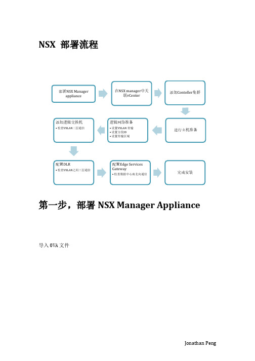
NSX 部署流程第一步,部署NSX Manager Appliance导入OVA 文件确认版本号选择NSX Manager的管理端口组,与vCenter通信使用。
确认EULA和选择部署的集群与存储后,对NSX Manager进行自定义,这里设置admin密码和CLI模式的密码。
展开Network Properties,填写NSX Manager主机名和配置管理的IPv4地址与vcenter通信使用展开DNS和Services Configuration,配置DNS和域名,配置NTP服务器信息注意:NSX的时间同步必须要与vcenter和esxi主机一致,时间敏感!确认配置信息,并完成Appliance部署。
第二步,设置NSX Manager与vCenter关联。
登陆https://172.20.21.3,使用admin和设置好的密码登陆NSX Manager管理页面。
(可选)选择Manager Appliance Settings,配置IP、NTP、主机名、DNS和备份恢复等信息。
选择Manage vCenter Registration配置SSO和vCenter信息,显示绿灯后NSX Manager配置完成。
第三步,配置NSX虚拟网络稍等一会,重新登陆vCenter主页(使用NSX注册vCenter SSO和vCetner服务的权限,如:administrator@vsphere.local),会出现Networking & Security控件和按钮,点击进入NSX管理页面。
1)点击Installation,可见NSX Manager信息,并按+添加首个Controller节点。
配置Controller信息,包括创建IP Pool用于Controller使用,Connected To的端口组,以及IP Pool地址是与NSX Manager通信使用。
Controller创建必须注意时间同步,创建成功。
- 1、下载文档前请自行甄别文档内容的完整性,平台不提供额外的编辑、内容补充、找答案等附加服务。
- 2、"仅部分预览"的文档,不可在线预览部分如存在完整性等问题,可反馈申请退款(可完整预览的文档不适用该条件!)。
- 3、如文档侵犯您的权益,请联系客服反馈,我们会尽快为您处理(人工客服工作时间:9:00-18:30)。
communication)
• Will start to see NIC support for high performance in the next year
▪ Extensibility of the header likely needed
Logical network (VNI)
Controller Cluster
DB
VM MACASPI (OVSDB)
Tunnels (VXLAN)
VVMVMM
vSwitch vSwitch
HypervvSiswoirtch HypervvSiswoirtch Hypervisor Hypervisor
costs ▪ Increase
agility
Cloud MAapnpagliceamtieonntsPlatform
Software Infrastructure
Hardware Infrastructure
34
Enabled By: ▪ Self-service
provisioning ▪ Automation via
Traditionally, these are coupled. For example, adding a new box often means downtime and configuration changes.
Provides ability to change performance characteristics on the fly.
Unified NSX Platform
From L2 – L7 Integration
27
NSX – The Network Virtualization Platform
Controller Cluster
Virtual Network
L2 L3 L2
CMP
VM
VM
“NSX API”
Software
• STT has 64-bit “context” vs 24-bit VNI
▪ Tunnel format decoupled from control plane ▪ Tunnel format != virtualization architecture
30
Hardware VTEPs
▪Benefits:
Visibility & Troubleshooting
VM VM
192.168.2.20 VM
VM VM
NSX vSwitch
Hypervisor
Disconnected
Virtual Network NSX vSwitch
Disconnected
Hypervisor
Disconnected
192.168.2.10 VM
28
Tunnels are like cables
Controller
Copper Cable Third party hardware
Virtual Network
WORLD
Hypervisor
VXLAN Cable
STT Cable
VXLAN Cable
Hypervisor
29
Why Not a Single Tunoptimize performance for
hypervisor-hypervisor traffic
• Leveraging commodity NIC behavior so that tunneling has
negligible performance impact
Disconnected
Physical Host
Disconnected Disconnected
10.35.188.80
Disconnected
Disconnected Disconnected
Physical Host
10.34.71.253
15
Ongoing Work : VCOPS Integration
• Fine-grained access: can pull a single physical port into the
virtual world
• Connect bare metal workloads with higher
performance/throughput
▪Same operational model (provisioning, monitoring) as
▪ 颠覆传统技术,打造软件定义数据中心
GCR Review Session for VMWorld Briefing
▪ Rick Chen VMWare NSBU
1
▪ #NET7388S
Agenda
▪ NSX Message Quick Update ▪ VMWare Message for Openstack ▪ Media Feedback and Response
VM VM
192.168.2.10 VM
NSX vSwitch
Hypervisor Physical Host
10.34.71.253
14
VM VM
192.168.2.20 VM
Virtual Network NSX vSwitch
Hypervisor
Physical Host
10.35.188.80
Resource
Anomaly score
Events Anomaly score
Possible root cause
Events
Alerts
Topology
Dynamic thresholds
Collected metrics Calculated metrics
16
Metric values
Virtual Network Health Monitoring & Troubleshooting
virtual networks
Consistent provisioning and operations for entire Data Center, regardless of workloads, over a simple IP fabric
31
Connecting the Physical to the Virtual
17
Physical Components Health Monitoring and Troubleshooting
18
Runtime Network Optimization
19
Network virtualization decouples correctness from performance network wide.
12
VM
VM
VM
NSX vSwitch
Hypervisor
Network virtualization provides visibility
Basic Idea
One Complex Network
13
Multiple Simple Networks
Visibility & Troubleshooting
APIs
Anatomy of a Cloud Management Platform
Tools for selfservice + automation, built on top of API
Applications
Web GUI CLI
SDK
Identity
Varies greatly by CMP: determines whether a request is allowed, updates external systems, decides what part of underlying infrastructure will host the workload
IP Underlay (no mulitcast required)
32
PHYMACS
Physical Workloads
▪ VMware Message for Openstack
33
Cloud Management Platforms (CMPs)
Business Goals: ▪ Reduce
• MPLS integration • Control plane federation • Policy frameworks • Flow-level tracking for fabric optimization •…
23
▪ NSX EcoSystem
24
VMware NSX Ecosystem
API Layer
CMP Logic
(governance, workflow, placement)
Driver Layer Cloud Management Platform
Software Infrastructure Hardware Infrastructure
35
Models available resources. Handles requests to create/ destroy/update and view current status
2
▪ NSX Message Quick Update
3
What is VMware NSX?