罗斯蒙特644温变安装指南
罗斯蒙特流量计安全操作及保养规程
罗斯蒙特流量计安全操作及保养规程罗斯蒙特流量计是一种用于测量液体或气体流量的设备,在工业、医疗、科研等领域广泛应用。
为了保证流量计的正常运行,延长使用寿命,必须遵循安全操作及保养规程。
一、安全操作规程1. 熟悉设备在使用罗斯蒙特流量计之前,需要仔细阅读使用说明书,并熟悉设备的结构、功能和性能特点。
应该了解流量计的测量原理,掌握正确的安装、调试和使用方法。
2. 戴防护装备在进行罗斯蒙特流量计的安装、调试和维护时,必须戴上适当的防护装备,如安全帽、防护眼镜、手套等。
特别是在进行焊接、打磨等作业时,要戴上防护面具和口罩,以免吸入有害气体和粉尘。
3. 正确使用工具在安装和维护罗斯蒙特流量计时,需要使用适当的工具,例如扳手、接头等。
要选择质量好、尺寸合适的工具,以免损坏设备,甚至造成人身伤害。
4. 遵守操作规程在使用罗斯蒙特流量计时,要按照操作规程进行操作,严禁进行任何未经授权或超出能力范围的操作。
操作前应当检查设备是否处于正常状态,如有异常应立即停机排除故障。
二、保养规程1. 定期检查罗斯蒙特流量计在使用过程中会受到环境、介质等多种因素的影响,因此需要定期检查设备的各个组成部分,如流量传感器、显示器、接线等,以发现问题及时进行修理。
2. 定期清洗为保证罗斯蒙特流量计的使用效果,需要定期对设备进行清洗。
清洗时应当采用适当的清洗剂,注意清洗时要不断更换清洗剂,以避免二次污染。
3. 正确存放在罗斯蒙特流量计不运行时,需要正确存放设备。
应避免与化学品、溶剂等有害物质接触,并保持设备的通风干燥。
4. 定期校准罗斯蒙特流量计需要定期校准,确保设备测量数据的准确性。
建议每年进行一次校准,或在设备出现异常时及时进行校准。
结论在使用罗斯蒙特流量计时,必须遵循安全操作规程和保养规程,保证设备的正常运行和使用寿命。
同时,需要加强对设备的熟悉和了解,掌握正确的操作方法,并及时处理设备故障。
罗斯蒙特储罐计量系统说明书

Rosemount™储罐计量系统一切挑战,尽在掌控散装液体存储解决方案目录艾默生帮您应对当下和未来的各种挑战为推动业务绩效,制造商面临规模不断增长的生产力和资源优化的需求。
通过罗斯蒙特储罐计量系统,您可以一直满足效率、安全、精度、可靠性和数据安全性需求。
您将获得精确的净体积库存计算,符合当前和未来最新的防溢罐保护标准。
无论您面临什么样的储罐计量库存测量挑战,我们的解决方案可帮助取得业务优质绩效:• 确保高效运营• 提升安全水平• 确保精确测量系统特性 4–7雷达液位测量 8-10温度测量 11库存管理软件与功能 12-13安全性:防溢罐、证明试验、浮顶监测14-18升级/扩展项目:模拟和无线通讯 19-23液化气全容储罐完整存储解决方案 24-25雷达储罐计量发明者的解决方案26-27运营数据,着手可得。
效率安全精度可扩展性实时访问精确数据促进工厂运营效率防溢罐保护解决方案满足 API 2350 和 IEC 61511 要求可靠的净体积计算,基于 API和 ISO 标准开放通讯标准使设备添加与更换更方便让您的罐区运营尽在掌控之中储罐计量的精度、可靠性和安全性根据 API 行业标准组织所规定,储罐计量系统应能够提供高精度的净体积和质量库存计算。
OIML 标准 R 85:2008 定义了贸易交接应用储罐液位计的最高精度要求。
损耗控制和质量平衡还要求高精度的库存测量。
此外,储罐计量装置为罐区提供基本的过程控制层。
独立的高液位指示器或液位开关则形成另一层保护。
这两个保护层中如果有未检测到的故障,可能会导致灾难性事故发生。
请相信,艾默生提供的可扩展的储罐计量系统解决方案可以满足此需求。
控制库存并准确了解储罐中产品存储量。
库存控制是一种关键的管理工具,涉及大型资产。
精确测量船只、口岸和管道输送系统之间的批次和贸易交接量。
石油动向和运营功能用于日常运作、调度和混合方案。
追踪泄漏并防止溢出,从而降低由于油品损耗造成的环境影响和财务损失。
罗斯蒙特644温度变送器

Bench Testing
2-2
测试设备
电源: 万用表: 电阻箱 热电偶信号发送器: 12–42.4 V dc 4 1/2 Digit
Fluke 8840A
0.01% 精度
General Resistance 热电阻-100
0.01% 精度
ECTRON 1120
回路负载: HART 通讯:
Minimum 250 欧姆
Bench Testing
2-4
接线盒
传感器接线端子
显示连接口 + 电源接线端子
_
Emerson Process Management - Educational Services - Rosemount Measurement - 644 Smart Temperature Transmitter Training - June 2006 - Copyrighted Material - Duplication Prohibited
Common Tasks
4-1
常用功能
本章节主要演示用HART 通讯实现常用功能。通 过本章学习后, 你将知道: 1. 选择输入传感器. 2. 更改PV单位. 3. 改变量程上限各下限值. 4. 组态离线. 5. 测试设备. 6. 回路测试.
Emerson Process Management - Educational Services - Rosemount Measurement - 644 Smart Temperature Transmitter Training - June 2006 - Copyrighted Material - Duplication Prohibited
Overview
罗斯蒙特流量计操作说明。中文

目录第一章传感器安装 (2)1.1概述 (2)1.2安装注意事项 (2)1.3传感器的安装方向 (3)1.4电气连接注意事项 (4)第二章仪表接线与上电 (5)2.1概述 (5)2.2变送器的型号识别。
(5)2.3变送器与传感器连接 (6)2.4最大布线距离 (7)2.5电源规格 (8)2.6变送器、显示组件方向调整 (9)2.7变送器输出 (11)第三章流量计组态 (14)3.1概述 (14)3.2组态项目 (14)3.3变送器的显示器面板结构 (15)3.4组态过程变量的测量单位 (15)3.5组态变送器的毫安输出 (16)3.6组态变送器的脉冲/频率输出 (16)3.7变送器的回路测试 (17)3.8 显示器菜单功能 (3)3.9流量计调零 (26)第四章流量计投用及报警状态 (27)4.1流量计投用 (27)4.2获取报警 (27)附录1报警代码含义表 (28)附录2核心处理器检查 (33)附录3传感器检查 (34)附录4软件版本4.x变送器的显示器菜单 (36)第一章传感器安装1.1 概述相对于其他类型的流量计,质量流量计具有安装简便、易于使用、测量精度高以及直接质量测量等优点,尤其是没有直管段要求的特点,用户可因地制宜的选择安装位置,节约安装成本。
1.2 安装注意事项1.2.1 安装位置应避免电磁干扰。
传感器、变送器的安装位置以及电缆铺设应尽量远离易产生强电磁场的设备,如大功率马达、变压器设施、变频设备等。
1.2.2 工艺管道应对中,两侧法兰应平行。
严禁用传感器硬行拉直上、下游工艺管道,否则将影响测量甚至损坏传感器。
另外在两侧的工艺管道近法兰处(约2~10倍管径处)应有稳固的支撑。
1.2.3 在传感器的上、下游管道上,建议安装截止阀及旁路以方便调零、日常维护及确保传感器在不工作时亦可处于满管状态。
使用流量计下游的调节阀进行流量控制。
1.2.4 在测量易汽化介质时,流量计下游建议安装压力表,供检查下游压力,流量计后建议工艺管与流量计保持同口径一段距离,以及流量计后有阀门可以用以调节适当的背压,防止汽化或气穴发生。
罗斯蒙特 3144P 智能温度变送器快速安装手册
5
罗斯蒙特 3144P
快速安装指南
00825-0106-4021,版本 CA 2004 年 11 月
第二步:设置开关
安全和故障模式开关位于电子模块的顶部中心位置。 按照下列步骤设置开关。
无液晶显示器
1. 将回路设置为手动 (如果适用)并断开电源。 2. 拆除电子元件外壳封盖。 3. 将开关设置为所需位置。再次连接外壳封盖。 4. 通电并将回路设置为自动控制。
Rosemount Division
Temperature GmbH
Asia Pacific Private Limited
8200 Market Boulevard
Frankenstrasse 21
1 Pandan Crescent
Chanhassen, MN USA 55317
63791 Karlstein
B
C
E
D
D = 现场接线线路配管 (dc 电源)
E = 延伸附件长度
3144-0433QIG
6
快速安装指南
00825-0106-4021,版本 CA 2004 年 11 月
罗斯蒙特 3144P
第三步 (续) ......
典型欧洲安装
1. 将热电偶套管安装于过程容器壁。安装并拧紧热电偶套管。进行泄漏检查。 2. 将顶部接线盒连接至热电偶套管。 3. 将传感器插入热电偶套管,将传感器与顶部接线盒接线 (接线图位于顶部接线盒内)。 4. 将变送器安装到 2 in(50 mm) 的管子上,或用可选的其中一个安装支架 (B4 支架如下图
1, 3, 4, 1, 2
USL (传感器上限)
1, 3, 4, 1, 6
3 变量映射
温度变送器模块安全操作及保养规程

温度变送器模块安全操作及保养规程1. 前言温度变送器模块是工控自动化控制系统中常用的一种设备。
通过将热电阻、热电偶等温度传感器所测量到的温度信号转换成标准的工业信号输出,实现对温度的监测、控制。
本文档将介绍温度变送器模块的安全操作和保养规程,以确保设备正常运行并延长其使用寿命。
2. 安全操作规程2.1 设备安装1.在安装前应对设备进行检查,确认设备符合要求,无受损或其他影响设备正常使用的缺陷。
2.按照设备说明书或技术要求,正确安装温度变送器模块,并配备相应的电源、信号线等。
3.在安装设备时,应避免将其暴露在明火或直接阳光下,以确保设备的安全运行。
2.2 设备使用1.在设备通电前,应检查电源线的连接是否正确并紧固,以确保电源的正常供应。
2.在使用设备过程中,应避免过度震动或撞击,防止设备疲劳损坏或者内部零部件松动。
3.不要在高湿度、高温度的环境下使用设备,以免影响设备正常使用,甚至导致设备故障。
4.如果设备出现异常情况,应立即停止使用,并与厂家联系,不要自行修理或拆卸,以避免加剧故障。
2.3 设备维护1.定期对设备进行检查和维护,清除设备内部的灰尘、杂物等物质,避免影响设备的正常运行。
2.定期检查设备的电源线、信号线等,确保其接头良好并无短路、断路等情况。
3.如果设备存在异常情况或报警,应立即停止使用,并进行检查,排除故障。
4.对于长时间不使用的设备,应将其存储在干燥、通风良好的地方,并当季节变化时,应及时对设备进行保养。
3. 保养规程3.1 清洁保养对温度变送器模块进行清洁保养可以去除灰尘、杂质,减少设备内部累积的水蒸气、雾气等物质,延长设备寿命。
1.充分断开设备的电源线和信号线,避免进行清洁时对人员造成伤害或对设备造成不必要的损伤。
2.用干净的清洁布或者软毛刷轻轻擦拭设备外壳,避免使用含有化学成分的清洁剂,以免对设备表面造成二次损伤。
3.定期进行设备内部清洁保养。
使用专业维护工具,如吸尘器或者压缩空气,将设备内部的灰尘、杂物、水蒸气等物质清除干净,并确保设备干燥通风。
罗斯蒙特 644 温度变送器快速安装指南说明书
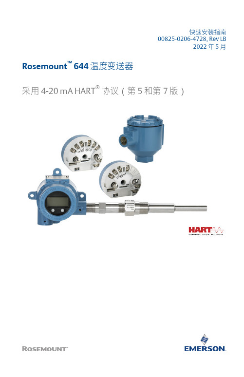
快速安装指南00825-0206-4728, Rev LB2022 年 5 月Rosemount™ 644 温度变送器采用 4-20 mA HART®协议(第 5 和第 7 版)快速安装指南2022 年 5 月内容关于本指南 (3)系统准备 (5)变送器安装 (6)安全仪表系统 (25)产品认证 (26)符合性声明 (44)中国 RoHS (52)2Rosemount 6442022 年 5 月快速安装指南1关于本指南本指南提供 Rosemount 644 温度变送器的基本安装指导。
但不提供组态、诊断、维护、检修、故障排除或安装的详细说明。
更多说明,请参阅Rosemount 644 参考手册。
手册和本指南的电子版本也可以从/Rosemount获得。
安全信息警告本文档描述的产品不是专为核工业级应用而设计的。
在需要核工业级硬件或产品的应用场合,若使用非核工业级产品会导致读数不精确。
有关罗斯蒙特核工业级产品的信息,请与本地艾默生销售代表联系。
遵照说明不遵守这些安装准则可能导致死亡或严重受伤。
确保仅由具备资质的人员进行安装。
物理接触未经授权的人员可能会对最终用户的设备造成明显受损和/或误组态。
这可能是有意或无意的,需要采取相应的防护措施。
物理安全措施是任何安全计划的重要部分,是保护您的系统的基础。
限制未经授权人员进行物理接触,以保护最终用户的资产。
这对于设施中使用的所有系统均是如此。
爆炸爆炸可能会导致死亡或严重受伤。
在危险环境中安装这些变送器时,请务必遵守适用的当地、国家和国际标准、规范和规程。
请核对产品认证一节中是否有与安全安装相关的任何限制。
电路带电时,请不要在易爆环境中拆除连接头护盖。
在易爆气体环境中,连接手持通讯器之前,请确保按照本质安全或非易燃现场接线实践安装仪表。
应验证变送器的工作环境是否与相应的危险场所认证一致。
所有连接头护盖必须完全盖好,以满足防爆要求。
快速安装指南3快速安装指南2022 年 5 月警告过程泄漏过程泄漏可能导致死亡或严重受伤。
罗斯蒙特温度变送器-通用传感器和热套管

一个现代化工厂的运作需要进行大量的温度测量。
罗斯蒙特每台传感器都具有过硬的质量和可靠性,会给您带来意想不到的收获。
为您的所有测量提供一贯的上乘
质量
温度传感器和热套管是高质量温度测量的最基本工具。
我们的热电阻、热电偶和热套管为温度测量带来了罗
斯蒙特一贯的可靠性,与温度变送器一起为您的过程
提供高精度和高可靠性的测量解决方案。
适用于您的通用传感器随时,随地
•生产制造能力完全可以满足您最大型和最复杂的项
目需求
•全球温度专家团队帮助您选择适合您过程的仪表
•传感器检验,提供一贯的开箱即用性能
•传感器、热套管和变送器一体化组合,易于采购,
方便安装
•将经过校准的传感器与罗斯蒙特变送器配对,提供卓越的精度水平。
有。
644温度变送器说明书

输入/验证 Callendar Van-Dusen 常数
若与这种变送器和传感器组合结合使用传感器匹配功能,应验证常数输入。
1. 在 Home 屏幕上,选择 1 设备设置,3 配置,2 传感器配置,1 传感器 1,3 校准 Van-Dusen。把控制回路设置为手动模式。选择确定。
2. 在提示输入传感器类型时,选择 Cal Van-Dusen。 3. 在提示输入传感器连接时,选择适当的接线数目。 4. 利用附接到专门订购的传感器的标牌信息,输入 Ro、Alpha、Beta 和 Delta 值。 5. 在把控制回路返回到自动控制模式之后,选择确定。
644R(开关在前面板中央)
1. 打开 644R 轨道安装型变送器的前门。 2. 把开关设置到所需位置。
罗斯蒙特 644
9
罗斯蒙特 644
快速安装指南
00825-0106-4728,BC 版 2011 年 2 月
第 4 步:安装变送器
在电缆管道的高点安装变送器,防止湿气进入变送器的外壳。
结束
¢00825-0106-4728[¤
罗斯蒙特 644
快速安装指南
00825-0106-4728,BC 版 2011 年 2 月
© 2011 罗斯蒙特有限公司。保留所有权力。所有标识均为其所有者的财产。Rosemount 和 Rosemount 标识均为罗斯蒙特 有限公司的注册商标。
罗斯蒙特 644
快捷键 1, 3, 2, 1 1, 3, 3, 3 1, 3, 3, 4 1, 1, 6 1, 1, 8 1, 3, 3, 3, 2 1, 3, 3, 1, 4 1, 3, 3, 1, 3 1, 1, 7 1, 1, 9 1, 1, 5 1, 3, 3, 2 1, 2, 2, 3 1, 3, 1 1, 3, 1, 5 1, 3, 4, 1 1, 3, 5 1, 2, 1 1, 3, 2, 1, 2 1, 2, 2, 1 1, 2, 2, 1, 2 1, 3, 2, 1, 1 1, 3, 2, 1, 1 1, 3, 2, 1, 4 1, 3, 5, 3 1, 3, 2, 2, 1, 3, 3, 1 1, 1 1, 1 1, 2, 1, 1 1, 2, 2, 1, 3 1, 3, 5, 4 1, 4 1, 2, 2 1, 3, 5, 1 1, 3, 3, 3, 1
Rosemount 248头部安装温度变送器快速安装指南说明书

快速安装指南00825-0206-4825, Rev CA2020 年 5 月Rosemount™ 248 头部安装温度变送器快速安装指南2020 年 5 月安全信息本指南提供 Rosemount 248 头部安装温度变送器的基本安装指导,但不提供组态、诊断、维护、检修、故障排除或安装的详细说明。
请参阅《Rosemount 248 温度变送器参考手册》获取更多说明。
手册和本指南的电子版本亦可以从/Rosemount获得。
警告爆炸爆炸可能会导致死亡或严重受伤。
在有爆炸危险的环境中安装本设备时,请务必遵守适用的当地、国家和国际标准、规范和规程。
请核对危险场所认证中是否有与安全安装相关的任何限制。
警告过程泄漏过程泄漏可能导致死亡或严重受伤。
在加压之前,应安装并拧紧热电偶套管和传感器。
在使用过程中不得拆卸热套管。
警告电力停供触电可能导致死亡或严重受伤。
不得接触引线或接线端子。
引线上可能存在的高压会导致触电。
除非另外标明,否则外壳中的导线管/电缆入口采用½–14 NPT 螺纹牙型。
标有“M20”的入口为M20 × 1.5 螺纹牙形。
在具有多个导线管入口的装置上,所有入口都采用相同的螺纹牙形。
在封闭这些入口时,只能使用具有相容螺纹牙形的堵头、接头、密封接头或导线管。
当在危险场所安装时,在电缆/导线管入口中仅使用已列出或通过 Ex 认证的适当堵头、密封套或接头。
警告物理接触未经授权的人员可能会对最终用户的设备造成明显受损和/或误组态。
这可能是有意或无意的,需要采取相应的防护措施。
物理安全措施是任何安全计划的重要部分,是保护您的系统的基础。
限制未经授权人员进行物理接触,以保护最终用户的资产。
这对于设施中使用的所有系统均是如此。
22020 年 5 月快速安装指南内容组态 (5)安装变送器 (7)接线 (11)执行回路测试 (16)认证安装 (17)产品认证 (18)快速安装指南3快速安装指南2020 年 5 月41组态1.1工作台标定有三种方式组态变送器:•现场通讯器•Rosemount 248 PC 编程工具包•在工厂中使用 C1 选项代码进行自定义有关更多信息,请参阅 Rosemount 248参考手册和现场手持通讯器用户指南。
罗斯蒙特质量流量计说明及操作规范,罗斯蒙特质量流量计中国总代理
罗斯蒙特质量流量计中国总代理(网址:),德莱美(北京)国际贸易有限公司中国总代理(网址:)罗斯蒙特质量流量计工作特性及原理,罗斯蒙特质量流量计中国总代理,罗斯蒙特质量流量计广泛应用于石化等领域,是当今世界上最先进的流量测量仪表之一,在我厂主要产品如乙烯、丙烯和主要原料轻烃等的测量中使用可靠,精度高达1.7‰,为我厂的能源、物料的流量测量提高了准确度,避免了不必要的损失,创造了可观的经济效益。
质量流量测量原理一台质量流量计的计量系统包括一台传感器和一台用于信号处理的变送器。
Rosemount质量流量计依据牛顿第二定律:力=质量×加速度(F=ma)如图1所示,当质量为m的质点以速度V在对P轴作角速度ω旋转的管道内移动时,质点受两个分量的加速度及其力:(1)法向加速度,即向心加速度αr,其量值等于2ωr,朝向P轴;(2)切向角速度αt,即科里奥利加速度,其值等于2ωV,方向与αr垂直。
由于复合运动,在质点的αt方向上作用着科里奥利力Fc=2ωVm,管道对质点作用着一个反向力-Fc=-2ωVm。
当密度为ρ的流体在旋转管道中以恒定速度V流动时,任何一段长度Δx的管道将受到一个切向科里奥利力ΔFc:ΔFc=2ωVρAΔx (1)式中,A—管道的流通截面积。
由于存在关系式:mq=ρV A所以:ΔFc =2ωqmΔx (2)因此,直接或间接测量在旋转管中流动流体的科里奥利力就可以测得质量流量。
传感器内是U型流量管(图2),在没有流体流经流量管时,流量管由安装在流量管端部的电磁驱动线圈驱动,其振幅小于1mm,频率约为80Hz,流体流入流量管时被强制接受流量管的上下垂直运动。
在流量管向上振动的半个周期内,流体反抗管子向上运动而对流量管施加一个向下的力;反之,流出流量管的流体对流量管施加一个向上的力以反抗管子向下运动而使其垂直动量减少。
这便导致流量管产生扭曲,在振动的另外半个周期,流量管向下振动,扭曲方向则相反,这一扭曲现象被称之为科里奥利(Coriolis)现象,即科氏力。
罗斯蒙特使用手册
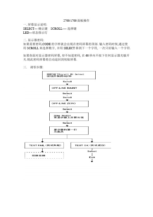
2700/1700面板操作一. 屏幕显示说明:SELECT--- 确认键 SCROLL---- 选择键LED---状态指示灯二. 显示器密码:如果需要密码,CODE的字样就会出现在密码屏幕的顶部. 输入密码时候,通过使用SCROLL来选择数字, 并用SELECT移到下一个字符, 一次只好输入一个字符.如果你面对显示器密码屏幕, 却不知道密码, 在60秒内不按下任何显示器光敏开关.则此密码屏幕将自动退回到初始屏幕.三. 调零步骤:四. 显示器回路测试:五. 显示器查看报警:LED指示灯状态及报警查看六. 管理累积量和库存量:七: 测量单位设置:SELECT+SCROLL 按4秒SEE ALARM [SCROLL]OFFLINE MAINTAIN [SELECT] [SCROLL]CONFIG [SELECT] MASS [SELECT]可以按SCROLL选择你要的单位选定后按SELECT按SCROLL直到出现EXIT [SELECT]体积单位和密度单位设置和上述步骤相同八量程设置(LRV URV)[SELECT+SCROLL] 按4秒SEE ALARM [SCROLL]OFFLINE MAINTAIN [SELECT] 继续按SCROLL直到出现MAO1 [SELECT] SRC MAO1 [SELECT]MFLOW [SELECT] SRC MAO1 [SCROLL]4 MAO1 输入最小量程 [SCROLL+SELECT] 4 MAO1[SCROLL] 20 MAO1 [SELECT] 输入最大量程 [SELECT+SCROLL] 20 MAO1 [SCROLL] EXIT 按SELECT退出.其他量程设置和上述步骤相同.NOTE: SELECT+SCROLL 表示两个键同时按下九: 报警代码和解决办法。
温度变送器选型安装规范

温度变送器选型安装规范 Jenny was compiled in January 20211、范围本规范规定了公司多相流量计设计中常用的铂(Pt)热电阻温度变送器选型、设计、安装的具体技术要求和检验规程。
其它同类型温度变送器亦应参照使用。
本规范适用于二线制温度变送器的选型,不包括其他类型的温度变送器。
公司所有温度变送器的设计、采购、验收和施工均不得低于本规范的要求。
2 、基本工作原理热电阻温度变送器是利用感温材料的电阻值和温度之间的数学模型关系,将随温度变化而变化的电阻值转换为4~20mA的直流电流信号或1~5V的直流电压信号输出。
3、构成与功能一体化温度变送器主要由温度传感器、保护套管、变送器等部分组成。
传感器将温度的变化转换成电阻值的变化。
保护套管用于隔离工艺介质,保护电阻体。
变送器将变化的电阻值转换成为变化的4~20mA(或1~5V)模拟信号输出。
4、主要技术性能4、1铂热电阻基本误差:A级±(+∣t∣)℃B级±(+∣t∣)℃注:t为感温元件实测温度允许通过电流:<5mA常温绝缘电阻:环境温度为15--35℃和相对湿度不大于80%时热电阻感温元件和保护管之间的绝缘电阻应不小于100MΩ(电压100V)。
热电阻插入最小深度:一般不小于其保护管外径的8---10倍。
4、2 变送器精度等级:0. 2级负载电阻:250Ω供电电源:24VDC ±10%环境温度:-25~70℃输出信号:4~20mA(或1~5V) DC测量范围:0~100(150)℃防爆等级:根据使用要求选用。
5、选型原则5、1 根据多相流量计装置的操作条件和使用场所,选用定型的、技术成熟可靠的产品。
对于新的产品,应在经过鉴定,确保质量的基础上选用。
5、2 在同一项目中,仪表品种规格不宜过多,并力求统一。
5、3 应根据现行的有关爆炸和火灾危险场所电气设备设计规范的规定,按一体化温度变送器安装场所的爆炸等级和爆炸性混合物的分类,确定其防爆形式及级别、组别。
变送器安装作业指导书
变送器安装作业指导书标题:变送器安装作业指导书文章内容:一、引言变送器是一种用于将物理量转换为可读的信号输出的设备。
在工业控制和自动化系统中,变送器的应用非常广泛。
为确保变送器的正确安装和使用,本文将详细介绍关于变送器的安装作业指导。
二、安全须知在进行变送器安装作业之前,请务必阅读并遵守以下安全须知:1. 请确保所使用的电源符合国家标准,并接地良好。
2. 在安装过程中,务必佩戴合适的个人防护设备,如手套、护目镜等。
3. 请勿在有电源的情况下进行触摸、拆卸或安装变送器。
4. 请确保工作场所通风良好,避免有害气体的累积。
三、准备工作在开始安装之前,请准备以下工具和材料:1. 水平仪2. 扳手3. 钳子4. 接线端子5. 导线6. 绝缘胶带7. 固定螺丝四、安装步骤1. 确定安装位置:根据实际需求确定变送器的安装位置。
通常情况下,变送器应安装在测量点附近,并保持与被测量介质的直接接触。
2. 固定变送器:使用合适的固定螺丝将变送器固定在安装位置上。
确保变送器与安装表面完全贴合,以保证传感器的准确度。
3. 连接导线:将导线的一端连接到变送器的信号输入端子上。
确保导线牢固连接,避免松动或接触不良。
4. 接地处理:将导线的另一端连接到接地端子上,确保变送器接地良好。
这有助于防止电磁干扰对变送器的影响。
5. 绝缘处理:对导线进行适当的绝缘处理,确保导线之间不会接触或短路。
6. 检查水平:使用水平仪检查变送器是否安装水平。
如果不水平,可使用扳手调整固定螺丝,使其水平。
五、调试和测试1. 供电测试:在接线完成后,供给变送器电源,并观察变送器的指示灯是否正常工作。
2. 数据测试:根据实际需求,使用测试仪器对变送器的输出信号进行测试,验证变送器的测量准确性和稳定性。
3. 故障排除:如果在测试过程中发现问题,可检查导线连接是否牢固,电源是否正常,以及是否有其他可能导致故障的因素。
六、维护保养1. 定期检查:定期检查变送器的外部情况,确保变送器没有受到损坏或污染。
Rosemount 644 温度传感器说明书

Quick Start Guide00825-0200-4728, Rev HCMay 2019 Rosemount™ 644 Temperature Transmitterwith 4–20 mA HART® Protocol (Revision 5 and 7)Quick Start Guide May 2019 Safety messagesThis guide provides basic guidelines for installing the Rosemount™ 644 Temperature Transmitter. Itdoes not provide instructions for detailed configuration, diagnostics, maintenance, service,troubleshooting, or installation. Refer to the Rosemount 644 Reference Manual for more instruction.The manual and this guide are also available electronically on /Rosemount.ImportantRead this manual before working with the product. For personal and system safety, and for optimum product performance, make sure to thoroughly understand the contents before installing, using, ormaintaining this product. The United States has two toll-free assistance numbers and one international number.Customer Central: 1-800-999-9307 (7:00 a.m. to 7:00 p.m. Central Standard Time)National Response Center: 1-800-654-7768 (24 hours a day). Equipment service needsInternational: 1-(952)-906-8888WARNINGPhysical accessUnauthorized personnel may potentially cause significant damage to and/or misconfiguration ofend users’ equipment. This could be intentional or unintentional and needs to be protected against.Physical security is an important part of any security program and fundamental to protecting yoursystem. Restrict physical access by unauthorized personnel to protect end users’ assets. This is truefor all systems used within the facility.WARNINGFollow instructionsFailure to follow these installation guidelines could result in death or serious injury.Ensure only qualified personnel perform the installation.WARNINGExplosionsExplosions could result in death or serious injury.Installation of the transmitters in a hazardous environment must be in accordance with theappropriate local, national, and international standards, codes, and practices. Please review theProduct Certifications section for any restrictions associated with a safe installation.Do not remove the connection head cover in explosive atmospheres when the circuit is live.Before connecting a handheld communicator in an explosive atmosphere, ensure theinstruments are installed in accordance with intrinsically safe or non-incendive field wiringpractices.Verify the operating atmosphere of the transmitter is consistent with the appropriatehazardous locations certifications.All connection head covers must be fully engaged to meet explosion-proof requirements./RosemountMay 2019Quick Start Guide WARNINGProcess leaksProcess leaks could result in death or serious injury.Do not remove the thermowell while in operation.Install and tighten thermowells and sensors before applying pressure.WARNINGElectrical shockElectrical shock could cause death or serious injury.Avoid contact with the leads and terminals. High voltage that may be present on leads can causeelectrical shock.ContentsSystem readiness (5)Transmitter installation (6)Safety instrumented systems (24)Product certifications (25)Quick Start Guide3Quick Start Guide May 2019 /RosemountMay 2019Quick Start Guide 1System readiness1.1Confirm HART® revision capability•If using HART based control or asset management systems, confirm the HART capability of those systems prior to transmitter installation. Not allsystems are capable of communicating with HART Revision 7 Protocol.You can configure thie transmitter for either HART Revision 5 or 7.1.2Confirm correct device driverProcedure1.Verify the latest Device Driver files are loaded on your systems toensure proper communications.2.Download the latest Device Driver at /Device-Install-Kits/Device-Install-Kit-SearchTable 1-1 provides the information necessary to ensure the correctDevice Driver files and documentation are being used.Table 1-1: Device Revisions and Files(1)NAMUR software revision is located on the hardware tag of the device. HART softwarerevision can be read using a HART communication tool.(2)Device Driver file names use Device and DD Revision, e.g. 10_01. HART Protocol is designedto enable legacy device driver revisions to continue to communicate with new HART devices.To access new functionality, download the new Device Driver. Emerson recommendsdownloading new Device Driver files to ensure full functionality.(3)HART Revision 5 and 7 Selectable, Dual Sensor support, Safety Certified, AdvancedDiagnostics (if ordered), Enhanced Accuracy and Stability (if ordered).Quick Start Guide5Quick Start Guide May 2019 2Transmitter installation2.1Set the alarm switchSet the alarm switch before putting the device into operation.Procedure1.Set the loop to manual (if applicable) and disconnect the power2.Remove the LCD display by detaching from the transmitter (ifapplicable).3.Set the switch to the desired position.H indicates High; L indicates Low.4.Reattach the LCD display to the transmitter (if applicable).5.Reattach the housing cover. Ensure covers must be fully engaged tomeet explosion-proof requirements.6.Apply power and set the loop to automatic control (if applicable).ExampleFigure 2-1: Alarm Switch PlacementAA. Alarm switchNoteIf using an LCD display, remove the display by detaching it from the top ofthe device, set the switch to the desired position, reattach the LCD display,and reattach the housing cover. Enclosure covers must be fully engaged tomeet explosion-proof requirements./RosemountMay 2019Quick Start Guide2.2Verify configurationUpon receiving your transmitter, verify its configuration using any HART®-compliant configuration tool. See the Rosemount™ 644 Reference Manualfor configuration instructions using AMS Device Manager.The transmitter communicates using the Field Communicator(communication requires a loop resistance between 250 and 1100 ohms).Do not operate when power is below 12 Vdc at the transmitter terminal. Seethe Field Communicator Reference Manual for more information.2.2.1Verify configuration with a Field CommunicatorTo verify configuration, you must install a Rosemount™ 644 DD (DeviceDescriptor) on the Field Communicator.Fast Key sequences for the latest DD are shown in Table 2-1. For Fast Keysequences using legacy DD's, contact your local Emerson representative.Perform the following steps to determine if an upgrade is required.Procedure1.Connect the sensor.See the wiring diagram located on the device’s top label.2.Connect the bench power supply to the power terminals (“+” or “–”).3.Connect a Field Communicator to the loop across a loop resistor or atthe power/signal terminals on the transmitter.The following message will appear if the communicator has a previousversion of the DDs:Device Description Not Installed…The DeviceDescription for manufacturer 0x26 model 0x2618 devrev 8/9 is not installed on the System Card…seeProgramming Utility for details on DeviceDescription updates…Do you wish to proceed inforward compatibility mode?If this notice does not appear, the latest DD is installed. If the latest version isnot available, the communicator will communicate properly; however, whenthe transmitter is configured to utilize advanced transmitter features, therewill be trouble communicating and a prompt to turn off the communicatorwill display. To prevent this from happening, upgrade to the latest DD oranswer NO to the question and default to the generic transmitterfunctionality.Quick Start Guide7Quick Start Guide May 2019 NoteEmerson recommends installing the latest DD to access the completefunctionality. Visit /Field-Communicator for information onupdating the DD Library.2.2.2Field Communicator user interfaceTwo user interfaces are available to configure this device.Figure 2-2 may be used for transmitter configuration and startup.Figure 2-2: Device Dashboard Field Communicator InterfaceTable 2-1: Device Revision 8 and 9 (HART® 5 and 7), DD Revision 1 FastKey Sequence/RosemountMay 2019Quick Start GuideQuick Start Guide9Quick Start Guide May 20192.2.3Input or verify Callendar Van-Dusen constantsIf using sensor matching with this combination of a transmitter and sensor,verify the constants input.Procedure1.From the HOME screen, select2 Configure→2 Manual Setup→1Sensor.2.Set the control loop to manual and select OK.3.At the ENTER SENSOR TYPE prompt, select Cal VanDusen.4.At the ENTER SENSOR CONNECTION prompt, select theappropriate number of wires.5.Enter the Ro, Alpha, Delta, and Beta values from the stainless steeltag attached to the special-order sensor when prompted.6.Return the control loop to automatic control and select OK.7.To disable the transmitter-sensor matching feature from the HOMEscreen select 2 Configure→2 Manual Setup→1 Sensor→10Sensor Matching-CVD.8.Choose the appropriate sensor type from the ENTER SENSORTYPE prompt./Rosemount2.2.4Verify configuration with local operator interface (LOI)The optional LOI can be used for commissioning the device. The LOI is a two-button design. To activate the LOI, push any button.LOI button functionality is shown on the bottom corners of the display. SeeTable 2-2 and Figure 2-4 for button operation and menu information.Figure 2-3: Local Operator InterfaceTable 2-2: LOI Button OperationFigure 2-4: LOI Menu2.2.5Switch HART® Revision modeNot all systems are capable of communicating with HART Revision 7Protocol. You can configure this transmitter for either HART Revision 5 or 7using a HART capable configuration tool.Updated configuration menus include a HART Universal Revision parameterthat can be configured to 5 or 7 if accessible by your system. See Table 2-1for the Fast Key sequence.If the HART configuration tool is not capable of communicating with HARTRevision 7, the configuration menus in Table 2-1 will not be available. Toswitch the HART Universal Revision parameter from generic mode, followthe instructions below.ProcedureGo to Configure→Manual Setup→Device Information→Identification→Message.a)To change your device to HART Revision 7, enter HART7 in theMessage field.b)To change your device to HART Revision 5, enter HART5 in theMessage field.NoteSee Table 2-1 to change HART Revision when the correct Device Driver isloaded.2.3Mount the transmitterMount the transmitter at a high point in the conduit run to prevent moisturefrom draining into the transmitter housing.2.3.1Head mount transmitter with DIN plate style sensor installationProcedure1.Attach the thermowell to the pipe or process container wall.2.Install and tighten the thermowell before applying process pressure.3.Verify the transmitter failure mode switch position.4.Assemble the transmitter to the sensor. Push the transmittermounting screws through the sensor mounting plate.5.Wire the sensor to the transmitter.6.Insert the transmitter-sensor assembly into the connection head.a)Thread the transmitter mounting screw into the connectionhead mounting holes.b)Assemble the extension to the connection head.c)Insert the assembly into the thermowell.7.If using a cable gland, properly attach the cable gland to a housingconduit entry.8.Insert the shielded cable leads into the connection head through thecable entry.9.Connect the shielded power cable leads to the transmitter powerterminals.Avoid contact with sensor leads and sensor connections.10.Connect and tighten the cable gland.11.Install and tighten the connection head cover.Enclosure covers must be fully engaged to meet explosion-proofrequirements.A.Connection head coverB.Connection headC.ThermowellD.Transmitter mounting screwsE.Integral mount sensor with flying leadsF.Extension2.3.2Head mount transmitter with threaded sensor installation (two orthree conduit entries)Procedure1.Attach the thermowell to the pipe or process container wall.2.Install and tighten thermowells before applying process pressure.3.Attach necessary extension nipples and adapters to the thermowell.4.Seal the nipple and adapter threads with silicone tape.5.Screw the sensor into the thermowell. Install drain seals if requiredfor severe environments or to satisfy code requirements.6.Verify the transmitter failure mode switch is in the desired position.7.Verify the correct installation of Integral Transient Protection (optioncode T1).a)Ensure the transient protector unit is firmly connected to thetransmitter puck assembly.b)Ensure the transient protector power leads are adequatelysecured under the transmitter power terminal screws.c)Verify the transient protector’s ground wire is secured to theinternal ground screw found within the universal head.NoteThe transient protector requires the use of an enclosure of at least3.5-in. (89 mm) in diameter.8.Pull the sensor wiring leads through the universal head andtransmitter center hole.9.Mount the transmitter in the universal head by threading thetransmitter mounting screws into the universal head mountingholes.10.Mount the transmitter-sensor assembly into the thermowell, orremote mount if desired.11.Seal adapter threads with silicone tape.12.Pull the field wiring leads through the conduit into the universalhead. Attach the sensor and power leads to the transmitter.Avoid contact with other terminals.13.Install and tighten the universal head cover.Enclosure covers must be fully engaged to meet explosion-proofrequirements.ExampleA.Threaded thermowellB.Threaded style sensorC.Standard extensionD.Universal head (transmitter inside)E.Conduit entry2.3.3Field mount transmitter with threaded sensor installationProcedure1.Attach the thermowell to the pipe or process container wall. Installand tighten thermowells before applying process pressure.2.Attach necessary extension nipples and adapters to the thermowell.3.Seal the nipple and adapter threads with silicone tape.4.Screw the sensor into the thermowell. Install drain seals if requiredfor severe environments or to satisfy code requirements.5.Verify the transmitter failure mode switch is in the desired position.6.Mount the transmitter-sensor assembly into the thermowell orremote mount if desired.7.Seal adapter threads with silicone tape.8.Pull the field wiring leads through the conduit into the field mounthousing. Wire the sensor and power leads to the transmitter.Avoid contact with other terminals.9.Install and tighten the covers of two compartments.Enclosure covers must be fully engaged to meet explosion-proofrequirements.ExampleAC BDEA.Threaded thermowellB.Threaded style sensorC.Standard extensionD.Field mount housing (transmitter inside)E.Conduit entry2.4Wire and apply power2.4.1Wire the sensor to the transmitterThe wiring diagram is located on the device’s top label below the terminalscrews.Figure 2-5: Rosemount™644 Head Mount TransmitterFigure 2-6: Rosemount 644 Head Mount - Single and Dual Input Wiring Diagrams•The transmitter must be configured for at least a three-wire RTD in order to recognize an RTD with a compensation loop.•Emerson provides a four-wire sensors for all single element RTDs. Use these RTDs in three-wire configurations by leaving the unneeded leads disconnected and insulated with electrical tape.Figure 2-7: Rosemount 644 Field Mount TransmitterFigure 2-8: Rosemount 644 Field Mount - Single and Dual Input Wiring Diagrams2.4.2Power the transmitterAn external power supply is required to operate the transmitter.Procedure1.Remove the housing cover (if applicable).2.Connect the positive power lead to the “+” terminal. Connect thenegative power lead to the “–” terminal.If a transient protector is being used, the power leads will now beconnected to the top of the transient protector unit. See thetransient label for indication of “+” and “–“terminal connections.3.Tighten the terminal screws. When tightening the sensor and powerwires, the max torque is 6 in-lb (0.7 N-m).4.Reattach and tighten the cover (if applicable).Enclosure covers must be fully engaged to meet explosion-proofrequirements.5.Apply power (12–42 Vdc).2.4.3Load limitationThe power required across the transmitter power terminals is 12 to 42.4Vdc; the power terminals are rated to 42.4 Vdc. To prevent damaging thetransmitter, do not allow terminal voltage to drop below 12.0 Vdc whenchanging the configuration parameters.2.4.4Ground the transmitterTo ensure proper grounding, it is important the instrument cable shield be:•Trimmed close and insulated from touching the transmitter housing.•Connected to the next shield if cable is routed through a junction box.•Connected to a good earth ground at the power supply end.NoteShielded twisted pair cable should be used for best results. Use 24 AWG orlarger wire and do not exceed 5,000 ft. (1500 m).2.4.5Ungrounded thermocouple, mV, and RTD/Ohm inputsEach process installation has different requirements for grounding. Use thegrounding options recommended by the facility for the specific sensor typeor begin with grounding option 1 (the most common).Ground the transmitter: option 1Procedure1.Connect sensor wiring shield to the transmitter housing.2.Ensure the sensor shield is electrically isolated from surroundingfixtures that may be grounded.3.Ground signal wiring shield at the power supply end.ExampleBACDCSDA.Sensor wiresB.TransmitterC.Shield ground pointD.4–20 mA loopGround the transmitter: option 2Procedure1.Connect signal wiring shield to the sensor wiring shield.2.Ensure the two shields are tied together and electrically isolated fromthe transmitter housing.3.Ground shield at the power supply end only.4.Ensure the sensor shield is electrically isolated from the surroundinggrounded fixtures.BACDCSDA.Sensor wiresB.TransmitterC.Shield ground pointD.4–20 mA loop5.Connect shields together, electrically isolated from the transmitter. Ground the transmitter: option 3Procedure1.Ground sensor wiring shield at the sensor, if possible.2.Ensure the sensor wiring and signal wiring shields are electricallyisolated from the transmitter housing.3.Do not connect the signal wiring shield to the sensor wiring shield.4.Ground signal wiring shield at the power supply end.BACDCSDA.Sensor wiresB.TransmitterC.Shield ground pointD.4–20 mA loop2.4.6Grounded thermocouple inputsGround the transmitter: option 4Procedure1.Ground sensor wiring shield at the sensor.2.Ensure the sensor wiring and signal wiring shields are electricallyisolated from the transmitter housing.3.Do not connect the signal wiring shield to the sensor wiring shield.4.Ground signal wiring shield at the power supply end.DCSACDA.Sensor wires B.Transmitter C.Shield ground point D.4–20 mA loop2.5Perform a loop testThe loop test command verifies transmitter output, loop integrity, andoperation of any recorders or similar devices installed in the loop.2.5.1Perform a loop test using a Field CommunicatorProcedure1.Connect an external ampere meter in series with the transmitter loop(so the power to the transmitter goes through the meter at somepoint in the loop).2.From theHome screen, enter the Fast Key sequence.3.In the test loop, verify the transmitter’s actual mA output and theHART ® mA reading are the same value.If the readings do not match, either the transmitter requires anoutput trim or the meter is malfunctioning.After completing the test, the display returns to the loop test screenand allows the user to choose another output value.4.To end the loop test, select End and Enter.2.5.2Perform a loop test using Device ManagerProcedure1.Right click on the device and select Service Tools.2.In the left navigation pane select Simulate.3.On the Simulate tab in the Analog Output Verification group box,select the Perform Loop Test button.4.Follow the guided instructions and select Apply when complete.2.5.3Perform a loop test using the LOIReference the figure below to find the path to the Loop Test in the LOImenu.Figure 2-9: Configuring the Tag with LOI3Safety instrumented systemsFor Safety Certified installations, refer to the Rosemount™ 644 ReferenceManual. The manual is available electronically at /Rosemountor by contacting an Emerson representative.4Product certificationsRev: 0.14.1European Directive InformationA copy of the EU Declaration of Conformity can be found at the end of theQuick Start Guide. The most recent revision of the EU Declaration ofConformity can be found at /Rosemount.4.2Ordinary Location CertificationAs standard, the transmitter has been examined and tested to determinethat the design meets the basic electrical, mechanical, and fire protectionrequirements by a nationally recognized test laboratory (NRTL) as accreditedby the Federal Occupational Safety and Health Administration (OSHA). 4.3North AmericaThe US National Electrical Code® (NEC) and the Canadian Electrical Code(CEC) permit the use of Division marked equipment in Zones and Zonemarked equipment in Divisions. The markings must be suitable for the areaclassification, gas, and temperature class. This information is clearly definedin the respective codes.4.4USA4.4.1E5 USA Explosionproof, Non-Incendive, Dust-IgnitionproofCertificate:[XP & DIP]: 3006278; [NI]: 3008880 & 3044581Standards:FM Class 3600: 2011, FM Class 3615: 2006, FM Class 3616:2011, FM Class 3810: 2005, ANSI/NEMA® 250: 2003,ANSI/IEC 60529: 2004Markings:XP CL I, DIV 1, GP B, C, D; DIP CL II / III, DIV 1, GP E, F, G; T5(–50 °C ≤ T a ≤ +85 °C); Type 4X; IP66; See I5 description for Non-Incendive markingsCertificate:1091070Standards:FM Class 3600: 2011, FM Class 3615: 2006, FM Class 3616:2011, UL Std. No. 61010-1-12, UL Std. No. 50E, CAN/CSAC22.2 No. 60529-05Markings:XP CL I, DIV 1, GP B, C, D; DIP CL II / III, DIV 1, GP E, F, G; T5 (–50 °C ≤ T a ≤ +85 °C); Type 4X; IP66;4.4.2I5 USA Intrinsic Safety and Non-IncendiveCertificate:3008880 [Headmount Fieldbus/PROFIBUS®, RailmountHART® ]Standards:FM Class 3600: 2011, FM Class 3610: 2010, FM Class 3611:2004, FM Class 3810: 2005, NEMA – 250: 1991Markings:IS CL I/II/III, DIV I, GP A, B, C, D, E, F, G; NI CL I, DIV 2, GP A, B,C, DSpecial Conditions for Safe Use (X):1.When no enclosure option is selected, the Rosemount 644Temperature Transmitter shall be installed in an enclosure meetingthe requirements of ANSI/ISA S82.01 and S82.03 or other applicableordinary location standards.2.Option code K5 is only applicable with a Rosemount enclosure.However, K5 is not valid with enclosure option S1, S2, S3, or S4.3.An enclosure option must be selected to maintain a Type 4X rating.Certificate:3044581 [Headmount HART]Standards:FM Class 3600: 2011, FM Class 3610: 2010, FM Class 3611:2004, FM Class 3810: 2005, ANSI/NEMA – 250: 1991,ANSI/IEC 60529: 2004; ANSI/ISA 60079-0: 2009; ANSI/ISA60079-11: 2009Markings:[No Enclosure]: IS CL I, DIV I, GP A, B, C, D T4; CL I ZONE 0 AExia IIC T4 Ga; NI CL I, DIV 2, GP A, B, C, D T5 [With Enclosure]: ISCL I/II/III, DIV 1, GP A, B, C, D, E, F, G; NI CL I, DIV 2, GP A, B, C,D; Type 4X; IP68Special Conditions for Safe Use (X):1.When no enclosure option is selected, the Rosemount 644Temperature Transmitter shall be installed in a final enclosuremeeting type of protection IP20 and meeting the requirements ofANSI/ISA 61010-1 and ANSI/ISA 60079-0.2.The Rosemount 644 optional housings may contain aluminum and isconsidered a potential risk of ignition by impact or friction. Care mustbe taken during installation and use to prevent impact and friction.Certificate:1091070Standards:FM Class 3600: 2011, FM Class 3610: 2010, FM Class 3611:2004, UL Std. No. 61010-1-12, UL Std. No. 50E, CAN/CSAC22.2 No. 60529-05, UL Std. No. 60079-11: Ed. 6Markings:IS CL I/ II/ III, DIV 1, GP A, B, C, D, E, F, G; CL I ZONE 0 AEx ia IIC;NI CL I, DIV 2, GP A, B, C, DSpecial Conditions for Safe Use (X):1.When no enclosure option is selected, the Rosemount 644Temperature Transmitter shall be installed in a final enclosuremeeting type of protection IP20 and meeting the requirements ofANSI/ISA 61010-1 and ANSI/ISA 60079-0.2.Option code K5 is only applicable with a Rosemount enclosure.However, K5 is not valid with enclosure options S1, S2, S3, or S4.3.An enclosure option must be selected to maintain a Type 4X rating4.The Rosemount 644 optional housings may contain aluminum and isconsidered a potential risk of ignition by impact or friction. Care mustbe taken during installation and use to prevent impact and friction.4.5Canada4.5.1I6 Canada Intrinsic Safety and Division 2Certificate:1091070Standards:CAN/CSA C22.2 No. 0-10, CSA Std C22.2 No. 25-1966, CAN/CSA-C22.2 No. 94-M91, CSA Std C22.2 No. 142-M1987, CAN/CSA-C22.2 No. 157-92, CSA Std C22.2 No. 213-M1987, C22.2No 60529-05, CAN/CSA C22.2 No. 60079-11:14, CAN/CSAStd. No. 61010-1-12Markings:[HART] IS CL I GP A, B, C, D T4/T6; CL I, ZONE 0 IIC; CL I, DIV 2,GP A, B, C, D[Fieldbus/PROFIBUS] IS CL I GP A, B, C, D T4; CL I, ZONE 0 IIC;CL I, DIV 2, GP A, B, C, D4.5.2K6 Canada Explosionproof, Dust-Ignitionproof, Intrinsic Safety andDivision 2Certificate:1091070Standards:CAN/CSA C22.2 No. 0-10, CSA Std C22.2 No. 25-1966, CSAStd. C22.2 No. 30-M1986, CAN/CSA-C22.2 No. 94-M91, CSAStd C22.2 No. 142-M1987, CAN/CSA-C22.2 No. 157-92, CSAStd C22.2 No. 213-M1987, C22.2 No 60529-05, CAN/CSAC22.2 No. 60079-11:14, CAN/CSA Std. No. 61010-1-12 Markings:CL I/II/III, DIV 1, GP B, C, D, E, F, GSee I6 description for Intrinsic Safety and Division 2 markings4.6Europe4.6.1E1 ATEX FlameproofCertificate:FM12ATEX0065XStandards:EN 60079-0: 2012+A11: 2013, EN 60079-1: 2014, EN60529:1991 +A1:2000+A2:2013Markings:II 2 G Ex db IIC T6…T1 Gb, T6(–50 °C ≤ T a ≤ +40 °C), T5…T1(–50 °C ≤ T a ≤ +60 °C)See Table 4-1 for process temperatures.Special Conditions for Safe Use (X):1.See certificate for ambient temperature range.2.The non-metallic label may store an electrostatic charge and becomea source of ignition in Group III environments.3.Guard the LCD display cover against impact energies greater than 4joules.4.Flameproof joints are not intended for repair.5. A suitable certified Ex d or Ex tb enclosure is required to be connectedto temperature probes with Enclosure option “N”.6.Care shall be taken by the end user to ensure that the externalsurface temperature on the equipment and the neck of DIN StyleSensor probe does not exceed 130 °C.7.Non-Standard Paint options may cause risk from electrostaticdischarge. Avoid installations that cause electrostatic build-up onpainted surfaces, and only clean the painted surfaces with a dampcloth. If paint is ordered through a special option code, contact themanufacturer for more information.4.6.2I1 ATEX Intrinsic SafetyCertificate:[Headmount HART]: Baseefa12ATEX0101X[Headmount Fieldbus/PROFIBUS]: Baseefa03ATEX0499X[Railmount HART]: BAS00ATEX1033XStandards:EN IEC 60079-0: 2018, EN 60079-11: 2012Markings:[HART]: II 1 G Ex ia IIC T6…T4 Ga; [Fieldbus/PROFIBUS]:II 1 G Ex ia IIC T4 GaSee Table 4-5 for Entity Parameters and Temperature Classifications.。
Rosemount 3144P 温度变送器快速安装指南说明书

快速安装指南00825-0106-4021, Rev SA2022 年 3 月Rosemount™ 3144P 温度变送器采用 HART®协议和 Rosemount X-well™技术快速安装指南2022 年 3 月内容关于本指南 (3)系统准备 (4)验证组态 (5)设置开关 (9)安装变送器 (10)接线和通电 (13)执行回路测试 (19)安全仪表系统 (SIS) (20)产品认证 (21)2Rosemount 3144P2022 年 3 月快速安装指南1关于本指南本指南提供了安装罗斯蒙特3144P 变送器的基本指导。
但未提供详细的组态、诊断、维护、保养、故障排除、防爆、防火或本质安全 (I.S.) 安装的说明。
更多说明,请参阅罗斯蒙特 3144P 变送器参考手册。
手册和本指南的电子版本也可以从/Rosemount获得。
警告爆炸爆炸可能会导致死亡或严重受伤。
在有爆炸危险的环境中安装本设备时,请务必遵守适用的当地、国家和国际标准、规范和规程。
请查阅本文档的“产品认证”一节,了解与安全安装相关的任何限制。
过程泄漏过程泄漏可能导致伤亡。
在加压之前,应安装并拧紧热电偶套管和传感器。
在使用过程中不得拆卸热套管。
导线管/电缆入口变送器外壳中的导线管/电缆入口采用½–14NPT 螺纹牙形。
当在危险场所安装时,在电缆/导线管入口中仅使用已列出或通过 Ex 认证的适当堵头、密封套或接头。
电力停供触电可能会导致死亡或严重伤害。
不得接触引线或接线端子。
引线上可能存在的高压会导致触电。
警告物理接触未经授权的人员可能会对最终用户的设备造成明显受损和/或误组态。
这可能是有意或无意的,需要采取相应的防护措施。
物理安全措施是任何安全计划的重要部分,是保护您的系统的基础。
限制未经授权人员进行物理接触,以保护最终用户的资产。
这对于设施中使用的所有系统均是如此。
快速安装指南3快速安装指南2022 年 3 月2系统准备2.1确认 HART®版本功能若使用基于 HART 的控制系统或资产管理系统,在安装变送器之前,请确认该系统的 HART 功能。
Emerson Rosemount 248 无线温度变送器安装指南说明书

快速安装指南00825-0306-4248, Rev BC2021 年 10 月Rosemount™ 248 无线温度变送器快速安装指南2021 年 10 月内容关于本指南 (3)无线注意事项 (5)物理安装 (6)验证操作 (9)参考信息 (12)电源模块更换 (16)产品认证 (18)符合性声明 (22)中国 RoHS (26)/Rosemount2021 年 10 月快速安装指南1关于本指南本指南提供 Rosemount 248 无线温度变送器的基本安装指导。
但不提供组态、诊断、维护、检修、故障排除或安装的详细说明。
请参阅《Rosemount 248 温度变送器参考手册》获取更多说明。
手册和本指南的电子版本亦可以从/Rosemount获得。
1.1安全信息警告不遵守这些安装准则可能导致死亡或严重受伤。
确保仅由具备资质的人员进行安装。
爆炸爆炸可能会导致死亡或严重受伤。
在有爆炸危险的环境中安装本设备时,请务必遵守适用的当地、国家和国际标准、规范和规程。
请核对危险场所认证中是否有与安全安装相关的任何限制。
过程泄漏过程泄漏可能导致死亡或严重受伤。
在加压之前,应安装并拧紧热电偶套管和传感器。
在使用过程中不得拆卸热套管。
电力停供触电可能导致死亡或严重受伤。
不得接触引线或接线端子。
引线上可能存在的高压会导致触电。
除非另外标明,否则外壳中的导线管/电缆入口采用½–14 NPT 螺纹牙型。
标有“M20”的入口为 M20 × 1.5 螺纹牙形。
在具有多个导线管入口的装置上,所有入口都采用相同的螺纹牙形。
在封闭这些入口时,只能使用具有相容螺纹牙形的堵头、接头、密封接头或导线管。
当在危险场所安装时,在电缆/导线管入口中仅使用已列出或通过 Ex 认证的适当堵头、密封套或接头。
快速安装指南3快速安装指南2021 年 10 月警告本设备符合 FCC 规范第 15 部分的规定。
设备操作应符合下列条件:本设备不会导致有害干扰。
248、644和3144温度快速接线

众所周知,罗斯蒙特是以温度起家的,基本温度变送器为温度测量点提供可靠的解决方案,尤其是推出的248、644和3144系列温度,深受广大客户的喜爱。
下面就给大家介绍这三款温度变送器的接线方式。
一、248可分为248H顶部安装型及248R导轨安装型变送器1、248H顶部安装型变送器由上图可看到248带外壳的变送器,模块中分为二个区域,电源区及接线区,*电源区外接24V电源;*传感器接线区接线方式具体如下(看连接图):红线接正极,白线接负级→2线制:红线接2(1、2串联),白线接3(3、4串联);→3线制:红线接2(1、2串联),白线接3、4;→4线制:红线接1、2,白线接3、4注意:串联情况仅为变送器未设置线制的情况,若客户所需线制与变送器线制一致,则无需串联。
2、248R导轨安装型变送器248R导轨型接线方式和248H顶部安装型一样,248温度变送器均为单传感器输入类型,此系列均不带显示。
二、644可分为单传感器输入(644H和644R)和双传感器输入类型644S1、单传感器输入644H由上图可看到644带外壳的变送器,模块中分为三个区域,电源区、报警开关及传感器接线区;*电源区外接24V电源;*报警开关:H和L表示故障模式,H表示高,L表示低;*单传感器接线区接线方式具体如下(看连接图):红线接正极,白线接负级→2线制:红接3(3、4串联),白接2(1、2串联);→3线制:红接3(3、4串联),白接1、2;→4线制:红接3、4,白接1、2注意:串联情况仅为变送器未设置线制的情况,若客户所需线制与变送器线制一致,则无需串联。
2、双传感器输入644S,双热电偶要特别注意正负极接线要正确,接线图如下:3、644R导轨式:接线图如下:三、3144P温度变送器可分为单传感器输入和双传感器输入1、3144P温度变送器单传感器输入2、3144P温度变送器双传感器输入注意事项:1、串联情况仅为变送器未设置线制的情况,若客户所需线制与变送器线制一致,则无需串联。
罗斯蒙特无线腐蚀变送器 IK220 安装包说明书
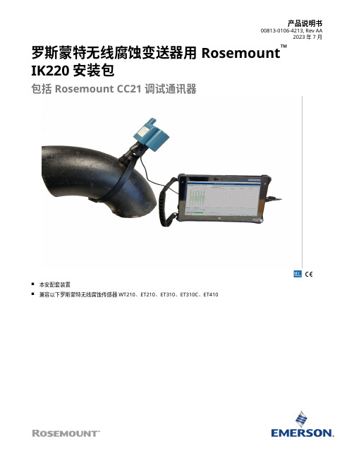
产品说明书00813-0106-4213, Rev AA2023 年 7 月罗斯蒙特无线腐蚀变送器用 Rosemount™IK220 安装包包括 Rosemount CC21 调试通讯器■本安配套装置■兼容以下罗斯蒙特无线腐蚀传感器WT210、ET210、ET310、ET310C、ET410Rosemount IK220 安装包2023 年 7 月Rosemount IK220 安装包变送器兼容性■Rosemount Wireless WT210 腐蚀变送器■Rosemount Wireless ET210 腐蚀变送器■Rosemount Wireless ET310 腐蚀变送器■Rosemount Wireless ET310C 腐蚀变送器■Rosemount Wireless ET410 腐蚀变送器订购信息Rosemount IK220 安装包目前仅作为备件提供。
备件编号取决于产品描述中的认证等级。
IK220 安装包随附 Rosemount CC21 调试通讯器。
如果 CC21 需要更换件,可单独订购。
内容Rosemount IK220 安装包 (2)订购信息 (2)Rosemount CC21 调试通讯器技术规格 (3)安装软件 (5)产品认证 (7)/Rosemount2023 年 7 月Rosemount IK220 安装包IK220 安装包随附卡箍安装工具。
如果 CC21 需要更换件,可单独订购。
Rosemount CC21 调试通讯器技术规格功能规格外壳等级IP67(配用变送器时)暔棟规奿材料选择艾默生罗斯蒙特产品有多种组态和型号包括广泛用于各种应用工况的结构材料。
本手册中的罗斯蒙特产品信息用于指导购买者为应用挑选合适的产品。
为特定应用选定产品、材料、选件和组件时购买者应谨慎分析所有过程参数(例如所有化学成分、温度、压力、流量、磨蚀性、污染物等等)。
艾默生无法评估或保证过程流体或其他过程参数与所选产品、选件、组态或结构材料的兼容性。