SCPI远程控制
powershell scpi指令
powershell scpi指令PowerShell与SCPI指令的应用一、介绍PowerShell是一种任务自动化和配置管理框架,广泛用于Windows操作系统。
而SCPI(Standard Commands for Programmable Instruments)是一套通用的测量仪器控制指令,常被用于仪器设备的控制和通信。
本文将讨论如何使用PowerShell编写和执行SCPI指令,以实现对测量仪器的远程控制。
二、PowerShell基础知识在开始讨论PowerShell与SCPI指令的应用之前,我们先了解一些PowerShell的基础知识。
PowerShell使用一种脚本语言,它基于.NET框架,并提供了强大的命令行解析能力。
PowerShell支持脚本编写、命令行操作、对象管道以及任务自动化等功能。
三、SCPI指令简介SCPI指令是一种面向测量仪表的通信协议,用于控制测量设备的功能和参数。
它定义了一套通用的命令格式和功能模块,使得不同厂家的测量仪器能够通过相同的指令进行控制和通信。
SCPI指令通常使用文本格式,并通过通信接口(如GPIB、LAN等)发送给测量仪器。
四、PowerShell中的SCPI指令执行在PowerShell中,我们可以通过一些特定的命令和模块来执行SCPI指令。
首先,我们需要确保计算机与测量设备之间建立了通信连接,比如使用GPIB接口或以太网连接。
然后,我们可以使用PowerShell中的相应命令来发送和接收SCPI指令。
五、发送SCPI指令要发送SCPI指令,我们可以使用PowerShell的`Write-Host`命令,该命令用于向终端输出文本。
我们可以将SCPI指令作为参数传递给`Write-Host`命令,并在终端上看到命令的执行结果。
例如,要发送一个查询命令,可以使用以下命令:```powershellWrite-Host "*IDN?" -NoNewLine```其中,`-NoNewLine`参数表示不换行输出。
程控仪器标准命令SCPI_通过串口或者gpib卡,vb_vc都能控制
5
第一节 SCPI的目标及主要内容
SCPI提供不同层次的仪器控制
简单的测量命令为用户提供方便快捷的SCPI仪器控制,而 更详细的命令则提供传统仪器的控制 SCPI允许不断用新命令扩充仪器程控命令,当新的仪器出 现时能够保持与已有的SCPI仪器的编程兼容性
SCPI的可扩性,是其成为“活”标准
哈工大测控所
9
第一节 SCPI的目标及主要内容
助记符的生成规则
长型助记符由一个单词或短语构成。如果是单词,则整个 单词构成助记符;如果是短语,则每个单词的第一个字符 和整个最后一个单词构成助记符
CONFIGURE --CONFigure remote message--RMESsage
10
第一节 SCPI的目标及主要内容
程控题头
公用命令与询问题头 仪器控制命令与询问题头 字符程控数据 十进制数值程控数据 布尔程控数据 单位和后缀
参数
哈工大测控所
11
第一节 SCPI的目标及主要内容
表达式
数值表达式 通道列表表达式 数值列表表达式 数据交换格式表达式 仪器指示表达式 事件状态寄存器结构 操作状态寄存器 可疑数据/信号状态寄存器
13
第一节 SCPI的目标及主要内容
3.数据交换格式
定义了仪器与应用程序之间、应用程序和应用程 序之间以及仪器与仪器之间数据集的标准的表示 形式 数据交换格式采样模块化结构
(1999版本)
4.仪器类别
主要是定义了通用的仪器类别功能实现所需的命 令和行为
(数字表、数字化仪、信号转接开关、电源、射频与微波源、 发射装置、发射测试单元、框架测力计)
智能仪器与PC串口通信的实现
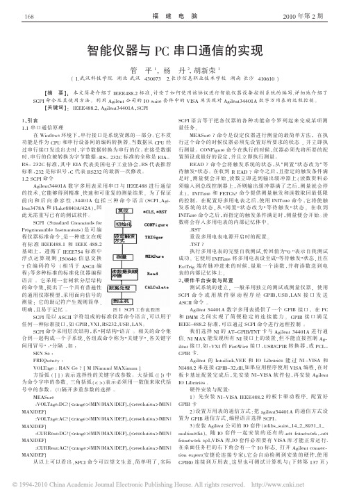
RS- 232C 标准,其中 EIA 代表美国电子工业协会,RS 代表推荐
标准,232 是标识号,C 代表 RS232 的最新一次修改。
1.2 SCPI 命令
Agilent34401A 数 字 多 用 表 采 用 串 口 与 IEEE488 进 行 通 信
的技术,它能够得到精准、快速和可重复的测量结果。 为了保证
.RST 重设多用电表电源开启时的配置。 .TST ? 执行多用电表的完整自我测试,传回值为"0 "表示自我测试 成功。 它使用 INITiate 将多用电表设至成"等待触发"状态,且在 ExtTrig 端 有 脉 冲 进 来 的 时 候 ,量 取 一 个 读 数 ,并 将 读 数 送 到 电 表的内部记忆体上。 2、硬件平台安装与配置 测试系统的建立, 一般采用独立的测试或测量仪器, 使用 SCPI 命 令 或 用 软 件 驱 动 程 序 经 GPIB,USB,LAN 接 口 发 送 ASCII 命令 。 Agilent 34401A 数 字 多 用 表 提 供 了 一 个 GPIB 接 口 , 在 PC 和 DMM 之 间 实 现 了 简 便 稳 定 的 连 接 能 力 。 GPIB 接 口 满 足 IEEE-488.2 标准,可以通过 SCPI 命令进行远程控制 。 我们选择 NI 的 AT-GPIB/TNT 卡与 Agilent 34401A 进 行 通 信. NI MAX 能发现所有 NI 接口上的装置,但不能直接控制 Agilent 接 口.如 :VXI 的 FireWire 接 口 ,USB/GPIB 转 换 器 ,或 PCLGPIB 卡. Agilent 的 Intuilink,VEE 和 IO Libraries 能 过 NI -VISA 和 NI488.2 来连接 GPIB-32.dll,如果应用程序使用 VISA 编程,在对 板 卡 基 址 配 置 完 成 后 ,先 安 装 NI-VISA 软 件 包 ,再 安 装 Agilent IO Libraries . 硬件安装与配置: 1) 先 安 装 NI-VISA IEEE488.2 的 板 卡 驱 动 程 序 . 配 置 好 GPIB 卡 2)设置万用表的通信方式:把 agilent34401A 的 通 信 方 式 设 置为 GPIB 通信方式,编程语言选择 SCPI。 3)安装 Agilent 公司的 IO 套件(iolibs_suite_14_2_8931_1_ multimedia), 随 IO 套 件 一 起 安 装 的 还 有 的 .net framework,.net framework sp1,VISA 库,IO 套件必须要有 VISA 库才能正常运行. 在桌面任务栏的右下角会有一个 IO 标志, 打开 Agilent connection expert(安 捷 伦 连 接 专 家),它 会 自 动 检 测 到 安 装 的 硬 件,使 用 GPIB0 连 接 到 万 用 表 ,这 里 也 可 测 试 计 算 机 与 (下 转 第 137 页 )
万用表scpi标准编程c语言

万用表SCPI标准编程C语言1.背景介绍万用表是一种用于测量电压、电流、电阻等物理量的仪器,是电工、电子工程师和科学家们日常工作中必不可少的工具。
而SCPI (Standard Commands for Programmable Instruments)是一种通用的仪器控制标准,它定义了一套用于控制和通信的命令集,使得不同厂家生产的仪器可以使用相同的命令进行控制和通信。
而C语言则是一种被广泛应用于嵌入式系统和仪器控制的编程语言,结合SCPI 标准和C语言,可以实现对万用表的编程控制。
2.万用表SCPI标准编程C语言的意义万用表SCPI标准编程C语言的意义在于提高仪器的自动化程度和效率。
传统上,仪器的操作需要人工干预,而借助SCPI标准和C语言的编程,可以实现对万用表的自动化控制,从而减少人力成本,提高工作效率。
3.步骤为了实现对万用表的SCPI标准编程,需要按照以下步骤进行操作:3.1 了解SCPI标准命令集需要了解SCPI标准的命令集,掌握各种命令的语法和使用方法。
SCPI 标准包括通用命令、系统命令、查询命令、控制命令等,通过学习和掌握这些命令,可以准确地实现对万用表的控制和通信。
3.2 编写C语言程序接下来,需要借助C语言编程,编写控制万用表的程序。
在程序中,需要包含对SCPI标准命令的调用,实现对万用表的控制和通信。
为了确保程序的稳定性和可靠性,需要考虑各种异常情况的处理,确保程序能够正确地控制万用表进行测量和操作。
3.3 调试和验证编写C语言程序后,需要进行调试和验证。
在调试过程中,需要逐步执行程序,检查程序的运行是否符合预期,发现并解决可能存在的问题。
在验证过程中,需要进行实际的测试,验证程序是否能够正确地控制万用表进行测量和操作。
3.4 优化和改进需要对程序进行优化和改进。
在实际应用中,可能会遇到各种问题和需求,需要根据实际情况对程序进行优化和改进,以适应不同的应用场景和需求。
4.应用举例一个简单的应用举例是使用SCPI标准和C语言编程控制万用表进行电压测量。
Linux命令高级技巧利用scp命令进行远程文件传输

Linux命令高级技巧利用scp命令进行远程文件传输Linux命令高级技巧:利用scp命令进行远程文件传输Linux操作系统是一种开源的操作系统,拥有强大的命令行工具,其中scp命令是实现远程文件传输的重要工具。
scp命令提供了安全可靠的文件传输方式,可以在本地主机和远程主机之间进行文件的传输和复制。
本文将介绍scp命令的常用用法和高级技巧,帮助读者更好地使用scp命令进行远程文件传输。
1. 基本用法scp命令的基本用法非常简单,下面是常用的格式:```scp [选项] 源文件目标文件```其中,源文件可以是本地主机上的文件或目录,也可以是远程主机上的文件或目录。
目标文件指定了文件传输的目标位置,可以是本地主机上的目录,也可以是远程主机上的目录。
例如,将本地主机上的文件mydoc.txt传输到远程主机的/home目录下:```scp mydoc.txt username@remote_host:/home```2. 远程传输scp命令既可以在本地主机上执行,也可以在远程主机上执行。
对于远程传输,需要指定远程主机的IP地址或域名,并提供登录用户名和密码。
远程传输的格式为:```scp [参数] 用户名@远程主机IP:源文件目标文件```例如,将远程主机上的文件remote_doc.txt传输到本地主机的/tmp 目录下:```scp username@remote_host:/home/remote_doc.txt /tmp```3. 文件传输的方向scp命令支持本地到远程的单向传输,也支持远程到本地的单向传输。
本地到远程传输的格式为:```scp [参数] 源文件用户名@远程主机IP:目标文件```远程到本地传输的格式为:```scp [参数] 用户名@远程主机IP:源文件目标文件```4. 文件传输过程中的参数scp命令提供了一些参数,可以对文件传输过程进行控制和优化。
常用的参数有:- -P:指定远程主机的端口号- -r:递归传输目录及其子目录下的所有文件- -p:保留文件的原有属性,包括时间戳和权限- -v:显示详细的文件传输进度和信息例如,使用scp命令进行文件传输时,可以加上-v参数查看传输进度和信息:```scp -v mydoc.txt username@remote_host:/home```5. 自定义端口号默认情况下,scp命令使用SSH协议的默认端口号进行传输(端口号为22)。
powershell scpi指令

powershell scpi指令在现代科学技术领域中,仪器设备的远程控制和自动化已成为必不可少的环节。
为了实现设备之间的通信和控制,SCPI(Standard Commands for Programmable Instruments)指令应运而生。
在本文中,将详细介绍PowerShell SCPI指令的基本概念以及其在仪器设备控制中的应用。
一、什么是SCPI指令SCPI全称Standard Commands for Programmable Instruments,即用于可编程仪器的标准指令集。
作为一种通用的控制命令语言,SCPI指令可用于各种测试和测量仪器,包括示波器、信号发生器等。
它通过通过一系列ASCII字符来进行仪器控制和操作。
SCPI指令的基本语法由主命令和可选的选择命令组成,并以回车符号作为结束符。
这种简洁的语法使得SCPI指令易于学习和使用。
值得注意的是,SCPI指令也支持查询功能,可以通过查询指令从仪器设备上获取数据。
二、PowerShell中的SCPI指令PowerShell是一种用于自动化任务和配置管理的脚本语言和命令行壳程序。
由于其功能强大且易于使用,PowerShell成为了许多系统管理员和开发人员的首选工具。
而在仪器设备控制方面,PowerShell也提供了许多方便的模块和命令,其中包括SCPI指令的执行和控制。
在PowerShell中,可以使用相应的插件或者模块来支持SCPI指令的解析和执行。
这些插件和模块提供了丰富的功能,包括发送和接收指令、解析返回的数据、错误处理等。
通过PowerShell中的SCPI指令,可以轻松地远程控制和自动化仪器设备的操作。
三、SCPI指令的应用场景1. 仪器设备远程控制SCPI指令的一个主要应用场景是仪器设备的远程控制。
通过PowerShell中的SCPI插件,可以通过网络或者串口等方式将指令发送到目标设备,实现仪器设备的启动、停止、设置参数等操作。
泰克示波器远程使用指南说明书
Working Remotely with Tektronix Oscilloscopes ––TECHNICAL BRIEFThere are several approaches you can take to Array work remotely with Tektronix oscilloscopes. The available techniques differ somewhat between instruments that run the Windows operating system and instruments that do not. This guide is designed to help you interface with your oscilloscope without needing to physically interact with the instrument after the initial setup. This document applies to most Tektronix oscilloscopes that do not have a PC operating system installed.Oscilloscopes that run the Windows operating system offer different alternatives for working remotely. The Technical Brief “Working Remotely with Tektronix Oscilloscopes Running the Windows Operating System”offers information on interfacing with Windowsoscilloscopes.2 | | 3Figure 1. The rear panel of a 6 Series MSO includes Ethernet LAN and USB device interfaces available for remote access.REMOTE CONTROL USING BUILT-IN WEB SERVERMany modern Tektronix oscilloscopes feature a built-in webserver called e*Scope. On the 4 Series MSO, 5 Series MSO, and 6 Series MSO, e*Scope is an easy to set up, real-time display and interface that runs on a web browser as if you were at the instrument with a mouse and keyboard. Anyone with the IP Address can simultaneously access and control the oscilloscope.On many entry-level and previous generation oscilloscopes, e*Scope is a remote User Interface that allows you to quickly see a snapshot of the oscilloscope display and make adjustments to settings and measurements. Examples of these oscilloscopes include TDS3000B, TDS3000C, DPO2000, MSO2000, DPO3000, MSO3000, MDO3000, DPO4000, MSO4000, MDO4000, 3 Series MDO and more.SETTING UP THE OSCILLOSCOPEe*Scope requires a network connection between a modern web-browser and an oscilloscope. The web-browser may be running on a computer, smartphone, or other device. The network connection can be a direct connection with an Ethernet cable, a Local Area Network connection with a network switch or router, over a VPN, or via an externally accessible IP Address. You may need your IT Department’s assistance or permission to connect the instrument to a network.When the oscilloscope is connected to a network that you can access, you need to find the oscilloscope’s IP Address. This istypically in a Utility or I/O configuration menu.Figure 2. Example of the I/O Menu on a 6 Series MSOIn the I/O settings, you can find an automatically configured IP address or set a static IP address. Make note of the IP addressto be ready to enter it into your web-browser’s address bar.Figure 3. Example of the LAN Settings on a 6 Series MSOACCESSING THE OSCILLOSCOPE THROUGH A WEB BROWSEREnter the oscilloscope’s IP Address into the address bar of a web-browser. When you navigate to that IP Address as if it were a website, the oscilloscope will present you with a Home page with several connection and configuration options, including a link toe*Scope. Click the link to e*Scope to connect to the oscilloscope for remote control.Figure 4. Example of the Home page connected to a 6 Series MSOFILE SHARINGNo file sharing method is built-in to e*Scope. The File Sharing section of this guide explains a method of mounting network drives that works nicely with most e*Scope instruments.TROUBLESHOOTING AND SUPPORTFor additional instrument-specific guidance on e*Scope, please refer to the Primary User Manual or Online Help Manual for that oscilloscope model on . You can also contact Tektronix technical support through /support orby asking your local Tektronix support contacts.4 | | 5TEKSCOPE PC WAVEFORM ANALYSIS SOFTWARE AND REMOTE SCOPE DATA ACQUISTIONTektronix offers a PC-based analysis application called TekScope that can allow you to analyze previously-saved waveforms for free, without connecting to an oscilloscope. You can also connect to one or more oscilloscopes as a paid service to pull real-time data from the remote scopes. You can access this software and see more details at .This software allows engineers to collaborate withoutnecessarily having to share physical access to an oscilloscope and provides increased flexibility in each individual’sworkflows. Consider the following examples of workflows that this software enables:• One engineer can take data in a lab and send it to several other engineers with this free software installed, and everyone can independently make measurements.• An engineer can spend one day in an instrumentation lab to collect a large set of data, but the rest of the week at their desk or out-of-office doing analysis.• As with other remote control options, users with the “Multi-Scope Analysis” option can connect directly to networked oscilloscopes to adjust instrument settings, collect newdata and transfer waveforms all from the TekScope interface to be viewed and analyzed in a centralized user interface.The TekScope interface duplicates the features and user-friendly interface of 4/5/6 Series MSOs. Any engineers that are familiar with those oscilloscopes will feel right at home with this software, and any unfamiliar users should find the interfaceeasy to pick up.Figure 5. TekScope software uses the same user interface as the 4, 5 and 6 Series MSOs. The basic analysis package is free. With the premium Multiscope option it can collect data from two oscilloscopes at once.TekScope supports importing waveforms in a variety of formats from a variety of vendors. Typical oscilloscope measurements, math capabilities, plots, cursors, etc. are available for free, while application-specific analysis features are available as paid services. For a summary of features and options, please see /#/packages .6 | FILE SHARINGEvery modern Tektronix oscilloscope has the capability to save Waveforms and Setups to internal and external storage. Habitually saving your work can make it easier to collaborate on-the-fly and look back at old projects. Anything from a TDS3000C oscilloscope to a 4 Series MSO to a DPO70000SX can save waveforms to a USB drive, for example. Many oscilloscopes can also be connected as a client to network drives for remote file management.Most recent non-Windows oscilloscopes, including DPO2000, MSO2000, DPO3000, MSO3000, MDO3000, DPO4000, MSO4000, MDO4000, 3 Series MDO, 4 Series MSO, 5 Series MSO, and 6 Series MSO have a File Utilities system through which you can mount a network drive as well.SAVING AND RECALLING FILESBoth direct and networked file management options can usually be accessed in the File menu of an oscilloscope. In the following example from a 6 Series MSO, the Recall selection can be used to load waveforms, setups, “sessions” (an all-in-one save type) and masks. The Save and Save As selectionscan be used to store screen captures, waveform data, setups, sessions and generate reports. The File Utilities selection is where you can connect to a network drive or do things like copy and paste, delete, and rename files on the oscilloscope’slocal memory.Figure 5. Example of the File menu on a 6 Series MSO.Figure 6. Example of saving a Session file on a 6 Series MSO.In the Save As menu, the save location can be altered with the “Browse” button. At the very least, the oscilloscope’s local memory (in this example, the C drive) will be accessible. If a USB Drive or Network Drive is connected, those locations will also appear as options.PREPARING A NETWORK DRIVE ON A WINDOWS PCConnecting to a Network Drive is often simple to configure on the oscilloscope but can sometimes be difficult to configure from a security and networking standpoint. The first step isto make some file, folder or directory accessible from a host server or computer to a network that the oscilloscope is on as well. The next step is to either Mount the network driveon a non-Windows oscilloscope or browse to it through File Explorer on a Windows Oscilloscope.As an example, to share from a Windows 10 PC, you can right click on a folder you wish to make your network drive, go to Properties, and then Sharing. In the new dialog that pops up, called Network Access, the list of Names are the users whose credentials can be used to access this shared folder. In other words, if left as the default, only your username and password can be used to access this new network drive, but you can optionally add more users or open the folder up to everyone on the network.When user access is configured as you like it, press Share in the Network Access dialog to finally host the network drive.The following image is an example of a simple configuration. Figure 7. Example of creating a shared folder on Windows 10. | 7MOUNTING THE NETWORK DRIVE FROM THE OSCILLOSCOPETo access this folder on a networked non-Windows oscilloscope, you can now go to File Utilities and enter the required fields. The following image shows a typical example of how each field maps to the folder settings in the previous image. An IP Address can be used instead of the server name.A more detailed walkthrough for this example is available at / support/faqs/how-do-i-set-network-drive-my-5-series-mso-or-6-series-mso.Figure 8. Example of mounting a network drive on a 6 Series MSO PROGRAMMATIC CONTROLNearly every Tektronix oscilloscope with an external communication port (e.g. GPIB, USB, Ethernet) can be controlled with remote commands. This is a powerful, flexible and scalable method of remotely controlling your instrument and automating measurements. There is a higher upfront development cost to get up and running when compared with the other methods available to you, but basic scripting is surprisingly easy to accomplish.Tektronix instruments use SCPI style commands which are industry standard ASCII strings and therefore language-agnostic, which means any language and environment can be used for control. Commonly used languages for this include Python (with PyVISA), MATLAB (with the Instrument Control Toolbox), LabVIEW, and the C-family.PROGRAMMING RESOURCESGuides on programmatic control and the variety of remote commands with detailed descriptions can be found in the instrument’s Programmer’s Manual. You can find this on , easily accessible by searching for your model number and filtering by“Manual” and then by “Programmer.”Figure 9. Example of searching for a programmer’s manual8 | Examples of scripts can be found around the internet. Tektronix resources include:• Tektronix online forum at /viewtopic.php?f=580&t=133570• Tektronix GitHub at /tektronix.In addition, the Tektronix Support YouTube channel has a video of getting started from the ground-up for free in Python here: /watch?v=W5Brxiwnp5g.INSTALL A VISAIt is important to be aware of VISA (Virtual Instrument Software Architecture) applications and to have one installed. VISA is an I/O API that is largely industry standard, with many Test and Measurement vendors supplying their own implementation. See /hardware-support/ni-visa-keysight-visa-tekvisa.html for a few examples. While in general which VISA you use should not matter, it sometimes does, and sometimes installing multiple VISAs can cause conflicts.Some additional standard protocol specifications that commonly manage I/O on top of VISA are USB-TMC forUSB control and VXI-11 for TCP/IP control. Some users choose to use Raw Sockets instead of VXI-11 based control over Ethernet.CONTROL WITH USB AND UTILITY APPLICATIONSMany oscilloscopes can be controlled over USB via theirUSB-B port. While USB control often results in lower throughput and latency than Ethernet-based control methods, USB provides a network-less and convenient connection. Often USB control uses SCPI commands, as discussed inthe Programmatic Control section of this guide, with a GUI on top. Three notable examples of applications that support USB connections are TekScope Utility, OpenChoice Desktop, and Keithley KickStart.TEKSCOPE UTILITY FREEWARETekScope Utility is a free utility application written by a Tektronix engineer with a simple, usable GUI with accessto commonly scripted features such as screenshot transfer, measurement logging, action-on-trigger, and waveformdata transfer. This utility supports most recent and several older Tektronix oscilloscopes range from entry-level toultra-high-performance.TekScope Utility freeware is available at / viewtopic.php?t=140451.Figure 10. Sample screenshot of TekScope UtilityOPENCHOICE DESKTOPOpenChoice Desktop is a free official utility application provided by Tektronix that supports the most common simple behaviors like screenshot and waveform transfer on many previous generation oscilloscopes.OpenChoice Desktop is available at /oscilloscope/tds210-software/tektronix-openchoice-desktop-application-tdspcs1-v26.KEITHLEY KICKSTARTKeithley KickStart is an inexpensive official software that supports a variety of Tektronix and Keithley instruments. Common simple behaviors on oscilloscopes are supported, but KickStart provides many built-in data collection behaviors on Keithley DAQs, SMUs, DMMs, and Power Supplies. Engineers working with Tektronix and Keithley instruments in tandem should consider Kickstart.Kickstart is available at /keithley-kickstart.There are many approaches to controlling and getting data from Tektronix oscilloscope that run the Windows operating systems. The approach you take depends on your application and may also depend on your company’s policies. | 9Find more valuable resources at Copyright © Tektronix. All rights reserved. Tektronix products are covered by U.S. and foreign patents, issued and pending. Information in this publication supersedes thatin all previously published material. Specification and price change privileges reserved. TEKTRONIX and TEK are registered trademarks of Tektronix, Inc. All other trade names referenced are the service marks, trademarks or registered trademarks of their respective companies. 060420 SBG 48W-61707-0Contact Information:Australia 1 800 709 465Austria* 00800 2255 4835Balkans, Israel, South Africa and other ISE Countries +41 52 675 3777Belgium* 00800 2255 4835Brazil +55 (11) 3759 7627Canada 180****9200Central East Europe / Baltics +41 52 675 3777Central Europe / Greece +41 52 675 3777Denmark +45 80 88 1401Finland +41 52 675 3777France* 00800 2255 4835Germany* 00800 2255 4835Hong Kong 400 820 5835India 000 800 650 1835Indonesia 007 803 601 5249Italy 00800 2255 4835Japan 81 (3) 6714 3086Luxembourg +41 52 675 3777Malaysia 180****5835Mexico, Central/South America and Caribbean 52 (55) 56 04 50 90Middle East, Asia, and North Africa +41 52 675 3777The Netherlands* 00800 2255 4835New Zealand 0800 800 238Norway 800 16098People’s Republic of China 400 820 5835Philippines 1 800 1601 0077Poland +41 52 675 3777Portugal 80 08 12370Republic of Korea +82 2 565 1455Russia / CIS +7 (495) 6647564Singapore 800 6011 473South Africa +41 52 675 3777Spain* 00800 2255 4835Sweden* 00800 2255 4835Switzerland* 00800 2255 4835Taiwan 886 (2) 2656 6688Thailand 1 800 011 931United Kingdom / Ireland* 00800 2255 4835USA 180****9200Vietnam 12060128* European toll-free number. If not accessible, call: +41 52 675 3777Rev. 02.2018。
用SCPI语言实现HP34401数字多用表的远程控制

6 位半分辨率 , O2 5 为 . 为 位半分辨率 , 00 为 4 为 . 2 位半
分 辨率 。
( ) 置测量 触发模 式 6设 发送 Ti e:or m da r grSuc I ei e g em t
式通信 . 航空计测技术 , O, () l 4. 2 42 4 : 一 2 0 4 4
关 键 词 : V40 ;C IR2 2 G I H 34 1S P; S3 ; PB
0 引言
I 34 1 H 公司生产的 6 - 40 是 P I P 位半数字多用表, 具有 交直流电压电流 、 线 2 电阻、 4 线 频率周期及二极管等多 种测量功能。通常采用手工设置仪器功能键, 人工记录 的方式进行数据测量。这种方法操作效率低, 且容易造 成误操 作 , 应用 数 字 多用 表后 面 板 附带 的 R 22串 口 而 S3 和 G I 口可以实现 仪器 的 自动化 测量 , 而提 高操 作 PB接 从 效率 。H 34 1 P40 的控制命令流也遵循 SP 命令格式 , CI 依 据仪器使用的设置步骤, 发送正确的命令流 , 并对返回状 态及测量数据信息进行处理 , 就可以实现数字多用表的 自动化测 量 。
无返 回字符串, 该命令用 于清除仪器 的当前状态标 志位 , 清除 Er 告警提示。 rr o
发送 Ss: e o /查 询测 量功 能 ytR m t e/
无返回字符串, I 34 1 使 - 40 处于远程控制状态 I P 发送 F N ? /查询仪器型号 UC / 返回 “ O T / V L ” /返回当前仪器设置的测量功能
宁揉 : SP 语 言实现 } ) 4 l 嗣 CI 壬3 o 数字多用表 的远程控 制 }4
用 S P 语 言 实现 H 3 4 1 字 多用 表 的远 程控 制 CI P40 数
实用技巧使用ssh和scp命令进行远程登录传输和管理

实用技巧使用ssh和scp命令进行远程登录传输和管理在计算机网络中,SSH(Secure Shell)是一种加密的网络协议,用于在不安全的网络上安全地进行远程登录和数据传输。
它提供了多种功能,从简单的远程命令执行到基于公钥的身份验证。
与之配套使用的SCP(Secure Copy)命令则是一种远程文件传输协议,通过SSH通道进行加密传输。
本文将介绍如何使用SSH和SCP命令进行远程登录、传输和管理。
一、使用SSH命令进行远程登录SSH命令可以连接到远程计算机,并在远程计算机上执行命令。
1. 打开终端(命令行界面)。
2. 输入以下命令(假设目标计算机的IP地址为x.x.x.x):``***************.x.x``其中,username为目标计算机上的用户名。
如果你是用于远程登录的计算机的当前用户,则可以省略用户名。
3. 输入目标计算机的密码。
如果你是第一次连接到目标计算机,系统可能会要求你确认目标计算机的指纹(fingerprint)。
输入“yes”来确认。
4. 成功登录后,你将进入目标计算机的命令行界面。
你可以在这里执行任意的命令。
二、使用SCP命令进行文件传输SCP命令可以在本地计算机和远程计算机之间进行文件传输。
1. 将文件从本地计算机上传到远程计算机:``scp/path/to/local/****************.x.x:/path/to/remote/directory``其中,/path/to/local/file为本地计算机上要传输的文件的路径,username为远程计算机的用户名,x.x.x.x为远程计算机的IP地址,/path/to/remote/directory为远程计算机上要保存文件的目录路径。
2. 将文件从远程计算机下载到本地计算机:``***************.x.x:/path/to/remote/file/path/to/local/directory``其中,/path/to/remote/file为远程计算机上要传输的文件的路径,/path/to/local/directory为本地计算机上要保存文件的目录路径。
SCPI程控指令学习实验指导书
STATus、SYSTem、TEST、TRACe|DATA、TRIGger、UNIT 和 VXI 等 23 个子系 统命令集。
利用 Agilent Connection Expert 根据仪器 IP 配置仪器后,主控机通过 LXI 总线发送 SCPI 命令控制仪器,并在用户界面上显示程控命令和结果。
自动设置视频带 宽 设置中心频率 根 据 Span 自 动 设置中心频率 设置中心频率步 进 设置频率 span 设置起始频率 设置终止频率 设 置 ACP 测 量 平均扫描次数 设 置 ACP 测 量 平均模式 设置计算主信道 功率的积分带宽 设置信道功率测 量平均扫描次数 设置信道功率测 量平均模式 设置计算信道功 率的积分带宽 CA 自动定标 LC 关闭所有的标记 ul 连续峰值搜索开 at 关
四. 实验原理
SCPI 的目标是缩短自动测试设备(ATE,Automatic Test Equipment)程序开 发时间。SCPI 通过为仪器控制和数据使用提供一致的编程环境来达成这一目标。 所有的 SCPI 仪器都使用定义好的程控消息、仪器响应和数据格式来实现兼容的 编程环境。
SCPI 提供几种不同层次的仪器控制,简单的测量命令为用户提供容易、快 速的 SCPI 仪器控制,与此同时,更详细的命令则可以用于提供传统仪器控制。
过冲测量 周期测量 上升时间测量 平均值测量 最大值测量 最小值测量 峰峰值测量 波 波形前缀 形 波形样点数 获 波形数据来源 取 波形数据格式 获取波形数据 状 管理状态报告 态 使能 管 读取状态报告 理 管理标准事件 寄存器 读取标准事件 寄存器 设置测量完成 状态报告
功能 系 识别 统 自检 功 复位 能 清除
实验一 可程控仪器标准代码(SCPI)学习
信号源的远程控制remote control

【FAQ】信号源的远程控制remote control现代矢量信号源一般具有远程控制功能,用户可以通过操作PC上的软件,实现对信号源的远程编程和控制。
最主要的连接接口有以下几种:∙General Purpose Interface Bus (GPIB) 通用接口总线使用GPIB IEEE-488.2,连接PC和信号源。
GPIB的数据单位是字节(8位),数据传输很快,在很多领域比如比如生产线上应用十分广泛。
然而,GPIB受仪器与PC之间物理位置和距离的限制。
传输电缆线平均不能超过2米/每仪器,总长不能超过20米。
∙Local Area Network (LAN)无线局域网LAN的数据单位是包(packet),传输速率较高。
电脑和信号源之间的距离最大不能超过100米(10base-T)。
下列协议适用于通过LAN与信号源连接: VXI–11 (推荐)Sockets LANTelephone Network (Telnet)File Transfer Protocol (FTP)∙ANSI/EIA232 (RS-232) 串行连接RS-232是与一台仪器通信常用的方式;主要用于控制打印机,外部磁盘驱动和连接到调制解调器。
通过RS-232连接速度较慢,因为数据的发送和接收的单次为1bit。
而且它需要某些特定的参数,比如波特率,在信号源和PC上能够匹配。
∙USB 2.0 (仅适用于安捷伦MXG)USB 2.0的64 MBps通信传输速率比GPIB和RS-232快(数据传输方面大于1KB)。
更多信息可以参考Agilent SICL 或VISA User’s Guide。
然而,小规模数据传输的延时会长一些。
安捷伦的信号源支持的接口列表如下:上述的这些接口,加上IO library和编程语言,可以远程控制信号源。
主要的编程语言与Commands for Programming Instructions (SCPI)和IO library功能一起远程控制信号源。
测控系统设计SCPI命令实验

院别: 控制工程学院课程名称: 测控系统设计实验教室: 6107指导教师: 蒋世奇小组成员(姓名,学号):汪洋令2011071070王州2011071067实验日期:2014 年10 月22 日评分:SCPI命令实验实验目的:练习使用SCPI命令,用SCPI命令远程遥控F120信号发生器,通过示波器查看信号发生器输出波形。
实验内容:熟悉SCPI的命令及命令格式;连接F120信号发生器与计算机串口;在盛普测试环境下练习这些命令,记录命令执行时所看到的现象,在示波器上观察信号发生器的输出;记住常用命令并熟练使用。
实验步骤:1、通过串口线,连接计算机和信号发生器RS232接口。
2、进入信号发生器系统设置界面,设置信号发生器COM,波特率,校验位等基本参数,如图所示:设置COM口为COM1:设置波特率为9600:设置校验位为8位无校验:3、打开盛普RS232/USB测试软件,输入SCPI命令,观察信号发生器和示波器变化。
(1)输入命令:APPLY:SQU 10.0 kHz,2.0 Vpp,-1.0 V即为发送10KHz方波,电压幅度为2伏,偏移-1伏。
信号发生器输出变化:示波器波形变化:验证正确。
(2)输入命令:APPLY:sin 5.0 kHz,5.0 Vpp,-3.0 V即为产生5KHz的正弦波,电压幅度为5V,偏移-3V。
观察信号发生器和示波器变化如图:命令验证正确。
再在以上输出波形基础上输入查询命令: APPL?得到信号发生器返回的查询命令如图所示:由以上信息可以得知SCPI命令验证正确。
再输入频率查询命令:frequency?返回结果如下:得到返回信息频率为5KHz,结果正确。
(3)输入三角波SCPI命令,产生5KHz频率,幅度3V,偏移-2V的三角波命令:appl: TRLANGLE 5.0 khz,3.0 vpp,-2.0 v信号发生器变化如图:示波器变化如图所示:由图可知,命令验证正确。
DS 数字衰减器SCPI命令集

DS 数字衰减器SCPI命令使用方法1 USB接口1.1 相关面板组件USB接口与相关的前面板按键如图1和图2所示。
图1 DAT64L前面板用户控制按钮图2 DAT64L后面板USB端口1.2 特性与规格用户可向数字衰减器发用SCPI命令,执行数字前面板用户控制按钮响应的功能,数字衰减器DAT64L接到命令后,可返回测量和计算数据、控制面板的设置参数。
1.3 接口说明标准USB接口,其带有免费的控制软件,基于 框架运行。
USB驱动程序将与任何终端程序一起使用,用于Linux,Unix,Mac,Android或者嵌入式系统中的命令控制。
1.4 本地和远程模式切换1 本地到远程模式DAT64L数字衰减器是通过标准USB供电,可以连接Micro-USB电源连接笔记本电脑,电池组,智能手机充电器,电脑等。
1)第一种情况当本地模式转换远程控制时,需通过USB线缆连接至电脑或者笔记本电脑,通过电脑设备管理器查找连接的USB COM端口号,添加COM端口号,点击“Connect”,如图3所示。
进入远程模式后,前面板的用户控制按键均失效图3 DAT64L软件控制界面2)第二种情况通常情况下,衰减器直接通过USB线缆连接至电脑,由软件界面控制,切换为本地控制式后,如何再次切换为远程控制模式,只需点击软件控制界面“Refresh”,直接恢复远程控制模式如图4所示。
图4 本地模式切换远程控制界面2 远程模式到本地控制切换DAT64L数字衰减器处于远程模式时,点击“* BUTTONS ON”发送命令,即进入本地模式,如图5。
前面板的用户控制按钮恢复正常操作在进入本地模式时,衰减器在远程模式的设置将保留图5 远程模式切换本地模式界面1.4 USB接口设置流程用户无需在衰减器上设置USB接口参数。
2 DAT数字衰减器系列命令集2.1 控制按钮命令2.1.1 *DISPLAY 打开显示器电源示例*DISPLAY ON*DISPLAY OFF2.1.2 *BUZZER 使蜂鸣器静音示例*BUZZER ON*BUZZER OFF2.2 重置命令2.2.1 *RST 重置衰减单位2.2.2 *IDN?返回识别SCPI字符串2.3 保存命令2.3.1 *SAVESTATE 将当前值保存为默认值2.3.2 *UNITNAME 将本机的文本名称保存到闪存示例*UNITNAME Joe2.3.2 *UNITNAME? 返回此单位名称2.4 设置衰减值命令2.4.1 ATT x 将衰减值设置为x示例ATT 30ATT 12.52.4.2 ATT? 返回当前衰减值INCR 增加1个步进值示例INCR2.4.3 INCR x 增加x单位示例INCR 5INCR 82.4.4 DECR 减小1个步进值示例DECR2.4.5 DECR x 减小x单位示例DECR 5DECR 22.82.4.6 STEP x 设置步进值为x示例STEP 2STEP 42.4.7 STEP?返回步进值。
PC机远程控制仪器的SCPI解析模块设计(最后发表)

PC机远程控制仪器的SCPI解析模块设计(西华大学)陈艳芬杨景常张吉涛(XiHua University)Chen,Yanfen Yang,Jingchang Zhang,Jitao 摘要:通过对SCPI(程控仪器标准命令)的研究,提出了一种应用于SCPI的解析模块。
该解析模块可适用于PC机和仪器间的各种接口,通过C语言编制的查表程序将PC机发出的SCPI消息解析为一组仪器可执行的二进制码。
此解析模块在实验室设计的多种仪器上进行了实验,证明了SCPI解析模块在可程控仪器中的可行性。
关键词:SCPI;程控仪器;C51;查表程序中图分类号:TP216 文献标识码:AThe design of SCPI parser module between PC and remote controlinstrumentsAbstract:Through the studying of SCPI(Standard Commands for Programmable Instruments),a parser module applied to SCPI is presented.The parser module can be the same with various interface between PC and instrments, procedure of looking up the table compiled by C parsed SCPI message from PC to a set of binary code that can be executed in instruments. The parser module was validated in multifarious instruments designed by our lab team,the feasibility of SCPI parser module in programmable instruments is proved.Key words:SCPI;Programmable instruments;C51;Procedure of looking up the table引言随着自动测试技术和程控仪器的发展,除了要求物理硬件接口标准化外,也要求软件控制标准化。
scpi指令使用例程

scpi指令使用例程SCPI (Standard Commands for Programmable Instruments)是一种用于控制和通信测试仪器的通信协议。
通过使用SCPI指令,用户可以编写程序来控制和操作仪器,实现各种测试和测量功能。
本文将介绍一些常见的SCPI指令使用例程,帮助读者理解和应用SCPI指令。
一、连接仪器在使用SCPI指令之前,首先需要建立与仪器的连接。
通常,连接仪器的方式有两种:通过串口连接或通过以太网连接。
下面是两种连接方式的例程:1. 通过串口连接:```pythonimport serial# 设置串口参数ser = serial.Serial()ser.port = 'COM1' # 串口号ser.baudrate = 9600 # 波特率ser.timeout = 1 # 超时时间# 打开串口ser.open()# 判断串口是否已打开if ser.is_open:print("串口已打开")else:print("串口打开失败")```2. 通过以太网连接:```pythonimport socket# 设置仪器IP地址和端口号ip_address = '192.168.0.1'port = 5025# 建立TCP连接sock = socket.socket(socket.AF_INET, socket.SOCK_STREAM) sock.connect((ip_address, port))# 判断连接是否建立成功if sock:print("连接已建立")else:print("连接建立失败")```二、发送和接收SCPI指令连接成功后,就可以通过发送和接收SCPI指令与仪器进行通信。
下面是发送和接收SCPI指令的例程:1. 发送SCPI指令:```python# 发送SCPI指令cmd = "*IDN?" # 查询仪器的ID信息sock.send(cmd.encode())# 发送后等待一段时间time.sleep(0.1)```2. 接收SCPI指令的返回值:```python# 接收SCPI指令的返回值recv_data = sock.recv(1024)result = recv_data.decode()# 打印返回值print(result)```三、常见的SCPI指令使用例程1. 查询仪器的ID信息:```python# 发送查询ID的指令cmd = "*IDN?"sock.send(cmd.encode())# 接收返回值recv_data = sock.recv(1024) result = recv_data.decode() # 打印返回值print(result)```2. 设置仪器的输出电压:```python# 设置输出电压为3Vcmd = "VOLTage 3"sock.send(cmd.encode())```3. 查询仪器的输出电流:```python# 发送查询输出电流的指令cmd = "CURRent?"sock.send(cmd.encode())# 接收返回值recv_data = sock.recv(1024) result = recv_data.decode() # 打印返回值print(result)```4. 执行仪器的自检功能:```python# 发送自检指令cmd = "SELFtest"sock.send(cmd.encode())```以上是一些常见的SCPI指令使用例程。
PC机远程控制仪器的SCPI解析模块设计

PC机远程控制仪器的SCPI解析模块设计
陈艳芬;杨景常;张吉涛
【期刊名称】《微计算机信息》
【年(卷),期】2009(25)1
【摘要】通过对SCPI(程控仪器标准命令)的研究,提出了一种应用于SCPI的解析模块.该解析模块可适用于PC机和仪器间的各种接口,通过C语言编制的查表程序将PC机发出的SCPI消息解析为一组仪器可执行的二进制码.此解析模块在实验室设计的多种仪器上进行了实验,证明了SCPI解析模块在可程控仪器中的可行性.【总页数】3页(P143-144,199)
【作者】陈艳芬;杨景常;张吉涛
【作者单位】610039,四川省成都市金牛区西华大学电气信息学院06级研究生班;610039,四川省成都市金牛区西华大学电气信息学院06级研究生班;610039,四川省成都市金牛区西华大学电气信息学院06级研究生班
【正文语种】中文
【中图分类】TP216
【相关文献】
1.SCPI命令解析器模块设计与实现 [J], 李伟;朱伟
2.SCPI命令解析器模块设计与实现 [J], 李伟;朱伟
3.基于SCPI语言的智能仪器LabVIEW驱动程序设计 [J], 迟明延
4.基于单片机的SCPI命令解析模块的设计与实现 [J], 张亮红;刘文怡;王红亮;刘伟
5.基于Hash散列的SCPI命令解析机制在LXI仪器上的实现 [J], 李智;秦昌明;张活
因版权原因,仅展示原文概要,查看原文内容请购买。
scpi编程语句中文解释
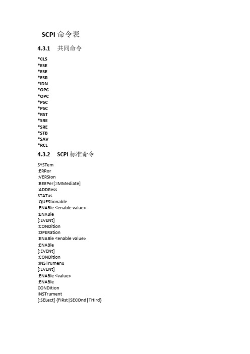
SCPI 命令表4.3.1共同命令*CLS*ESE*ESE*ESR*IDN*OPC*OPC*PSC*PSC*RST*SRE*SRE*STB*SAV*RCL4.3.2SCPI 标准命令SYSTem:ERRor:VERSion:BEEPer[:IMMediate]:ADDRessSTATus:QUEStionable:ENABle <enable value>:ENABle[:EVENt]:CONDition:OPERation:ENABle <enable value>:ENABle[:EVENt]:CONDition:INSTrumenu[:EVENt]:ENABle <value>:ENABleCONDitionINSTrument[:SELect] {FIRst|SECOnd|THIrd}[:SELect]NSELect {1|2|3}NSELectOUTPut[:STATe] {0|1}[:STATe][SOURce:]CURRent[:LEVel][:IMMediate][:AMPLitude] {<current>|MIN|MAX} CURRent[:LEVel][:IMMediate][:AMPLitude] {MIN|MAX} VOLTage[:LEVel][:IMMediate][:AMPLitude] {<voltage>|MIN|MAX} VOLTage[:LEVel][:IMMediate][:AMPLitude] {MIN|MAX} VOLTage:PROTection[:LEVel][:IMMediate][:AMPLitude] VOLTage:PROTection[:LEVel][:IMMediate][:AMPLitude]非SCPI标准命令CALibration:SECure[:STATe] {ON|OFF,<quoted code>}:SECure[:STATe]:VOLTageLEVel <level>[:DATA] <voltage value>:CURRentLEVel <level>[:DATA] <current value>:CODE:SAVe:INITitalOUTPut25:TIMer:DATA <time>:DATASYSTem:LOCal:REMote:RWLockDISPlay:[:WINDow][:STATe] {OFF|ON}[:WINDow][:STATe]MEASure[:SCALer]:CURRent[:DC][:VOLTage][:DC]:POWer[:DC]4.4.1 SCPI状态寄存器你可以通过读取操作状态带存器的苴米喷定电源的当前状态.电源逋长七个状态寄存器组记录了不同的仪器状态,这七个状态寄存薜组分为状态位组寄存器,标准型件寄存器,查询状态寄存器和操作状态符存器(包含三.个子寄存器3状态位把寄存器记录了其它状态寄存器的信息.下点绐出了各个状态寄存器的定义.下图定义了电媪状态寄存器的结构INST 1IHCTZI 幅3Ts置时或茅琪事件赤存在condrtlori ewem各为今露中位悔住定如古田所示,录低位 .也匕录高位在下SCPI 解释共同命令*CLS这条命令清除下面的寄存器:标准事件寄存器、查询事件寄存器、操作状态寄存器、操作状态子寄存器、状态字节寄存器的错误信息。
- 1、下载文档前请自行甄别文档内容的完整性,平台不提供额外的编辑、内容补充、找答案等附加服务。
- 2、"仅部分预览"的文档,不可在线预览部分如存在完整性等问题,可反馈申请退款(可完整预览的文档不适用该条件!)。
- 3、如文档侵犯您的权益,请联系客服反馈,我们会尽快为您处理(人工客服工作时间:9:00-18:30)。
SCPI远程控制AT-PG-1000系列
AT-PG-1000系列,包含PG-1072和PG-1074两个型号的脉冲发生器,高达4通道输出脉冲。
前置控制板按钮和高清触摸显示屏,Windows10操作系统,如图1所示。
即可通过软面板控制按钮控制仪器输出,也可以直接点击触摸屏控制,同时通过发送SCPI命令也可远程操作仪器。
其操作方法如下
图1 PG-1074(4通道,1072-2通道)
1 安装AT-Instrument-Communicator
登录www.activetechnologies.it官网下载SDK软件包,选择Pulse Rider PG-1000产品,点击AT-PG1072或者AT-PG1074下载附件,如图2,点击下载,并且安装“AT-Instrument-Communicator”(SDK附件包含AT Instrument Communicator setup,SCPI命令手册和Labview 2013例程)。
图2 AT-PG1000 SDK下载界面
2 NI VISA
VISA提供硬件和开发环境之间的编程接口,如Visual ,LabVIEW,LabWindows/CVI,Measurement Studio for Microsoft Visual Studio和MatLab。
NI-VISA是NI实施的VISA I/O标准,包括软件库,NI I/O Trace和VISA交互式控制等互式实用程序,以及通过Measurement&Automation Explorer满足您所有开发需求的配置程序。
登录National Instruments /nisearch/app/main/p/bot/no/ap/tech/lang/it/pg/1/sn/catnav:du,n8:3.1637,ss nav:sup/下载符合您电脑版本的NI-VISA驱动程序,并且安装。
安装成功后,使用LAN线缆连接仪器和主机PC,启动NI-MAX。
点击“设备与接口”,选择“网络设备”,右击“新建”,添加“VISA TCP/IP Resource”,如图3。
图3 新建网络设备界面
然后出现以下界面,图4所示,选择“Auto-detect of LAN Instrument”,点击下一步
图4 新建VISA TCP/IP Resource界面
出现图5界面,按着图中的选项选择,并点击下一步
图6中选择完成,完成了新建VISA TCP/IP Resource,如图7所示。
图6 新建VISA TCP/IP Resource界面
点击图7中“打开VISA测试面板”,如图8所示,显示其配置信息,I/O设置。
图8 VISA测试面板
3 SCPI命令远程控制
添加上网络设备后,打开“AT-Instruments-Communicator”软件,如图9所示,选择之前
添加的TCP/IP Resource,点击“Connect”,连接设备,command命令行可发送命令,表示连
接成功,如果显示灰色,表示连接失败,重新连接,查找连接失败的原因。
连接成功后,发送SCPI命令,控制仪器输出,如图10中发送命令“SOURce1:VOLT:HIGH 2”,
点击Query发送,将输出高电压改为2V,显示界面如图11所示。
图9 AT-Instrument-Communicator界面
图10 SCPI命令发送界面
图11 SCPI命令更改仪器输出后显示界面
同样的方法,发送SCPI命令“*RST”,重置仪器输出,恢复默认值,如图13所示。
图12 SCPI命令发送界面
图13 仪器默认输出界面
以上操作过程就完成SCPI远程控制AT-PG-1000系列,其完整SCPI命令见附录。
附录
基本控制的SCPI命令如下:
*IDN?
*RST
SOURce1:PERiod 600 ns
SOURce2:PERiod 200 ns
SOURce1:VOLT:HIGH 1
SOURce1:VOLT:LOW -1
SOURce2:VOLT:HIGH 0.5
SOURce2:VOLT:LOW -0.5 SOURce1:PULSe1:WIDth 100 ns SOURce2:PULSe1:WIDth 20 ns SOURce1:PULSe:MODE SINGLE TRIGger:MODE CONTINUOUS PULSEGENControl:START
*TRG。