美军技术标准MIL-PRF-38534-RevE
美国军用标准
美国军用标准(MIL-PRF-13830B)性能标准军火控制设备用光学元件;监控生产、装配、检测的通用标准所有防御和代理部门可允许使用此种标准。
1. 范围1.1 范围。
此标准包括精加工光学元件的生产、装配、检测,诸如:透镜,棱镜,面镜、光栅、窗口以及用于防火仪器或设备。
2.应用文件2.1本章列出的文件需要满足本标准3、4、5章的要求。
本章不包括本标准其他章节的文件或其他信息推荐的文件。
为了保证本目录的完整性,文件使用者必须注意文件须满足本标准3、4、5章列出的文件要求,无论这些内容是否在本章中列出。
2.2 其他政府文件,图纸及出版下列政府其他文件、图纸和出版组成本文件内容的一部分,扩大本文的范围。
除非另有规定,这些文件、图纸和出版是征求引用的。
图纸 C7641866---光学元件表面质量标准(立约人要求的其他政府文件、图纸、出版复印件及具体的功能应该从签约事宜或签约指示得到。
)2.3 优先顺序本标准内容与其引出的参考有冲突时,以本标准内容为准。
本标准未述内容,可行法律法规代行除非有具体的免除通知。
(看附加有限标准合同条令)3.要求:3.1所有的光学元件,配件以及系统产品都必须符合这一标准的要求,除非具体的仪器标准或合同之可行图纸另有要求与定义。
3.2所用的材料也必须与图纸的说明以及使用文件的标准相一致3.2.1玻璃光学元件在规格,以及级别必须与图纸要求相一致。
允许使用玻璃材料时,应提供给合同管理人员相关的玻璃光学特性及设计数据完整的信息。
3.2.1.1 放射性材料本文中要求的光学材料应不含钍或其他加入的超过0.05%重量的放射性材料。
3.2.2 粘着力除非合同和定单中有特殊说明,光学粘合剂必须同附录A的要求相一致。
3.2.3 粘连材料对于玻璃同金属相粘连,必须与附录D的要求相一致3.2.4密封材料用于密封的材料必须与附录E的要求相一致3.2.5 增透膜用于光学表面镀膜的增透膜必须与附录C的要求相一致3.2.5.1 反射表面铝化反射面必须与附录B的要求相一致3.3机械尺寸大小光学元件必须与合同以及图纸的要求的尺寸和光学数据相一致3.3.1边所有光学元件都应当倒边在(0.020-0.005英寸在45度+/-15度),沿面宽进行测量,除非有特殊指定。
舰船中压配电设备美军标研究

舰船中压配电设备美军标研究杨青(海军驻上海711所军事代表室,上海201108)摘要:对舰船中压配电设备美军标的概况进行了分析;对中压交流配电板、中压交流真空断路器、中压交流真空断路器用保护继电器等美军标进行了研究;并结合相 关产品的情况,得出了舰船中压配电设备美军标的技术特点,提出了我国舰船中压配 电设备标准化的建议。
可为我国舰船中压配电设备研制和标准化工作提供参考。
关键词:中压;配电设备;舰船;M IL 标准中图分类号:TM 64文献标志码:A 文章编号:2095-8188(2017)06-0083-06D O I : 10.16628/j. cnki. 2095-8188. 2017. 06. 016Research on American Military Standards for MediumVoltage Electrical Distribution Equipment on ShipsYANG Qing(Naval Representatives Office at No . 711 Research Institute , Shanghai 201108, China )Abstract : The general profile of American military standards for medium voltage electrical distributionequipment on ships was introduced, and American military standards for medium voltage switchgear, medium voltage AC vacuum circuit breaker and its protection relay were analyzed. Combined with the status of corresponding products, after the technical features of American military standards for medium voltage electrical distribution equipment are summarized, the suggestions for developing Chinese standards for medium voltage electrical distribution equipment on ships were proposed, which would provide reference for the design, manufacture and standardization of medium voltage electrical distribution equipment on ships in China.Key words : medium voltage ; electrical distribution equipment ; ship ; military standard杨青(1967—),男,高级工程师,博 士,主要从事舰船 电力系统和电气设 备方面的工作。
美国军用标准MIL

美国军⽤标准MIL柔性可热封静电防护材料特性规范美国军⽤标准MIL-PRF-81705D上海防静电⼯业协会王福良译本规范已批准⽤于军队的所有部门与国防部承包商。
1 范围1.1范围本规范建⽴了⼀套军⽤微电路、敏感半导体器件,敏感电阻和相关⾼档部件的柔性可热封静电防护包装材料的要求。
另外I型材料可提供防⽔防电磁辐射的性能(见6.1)。
1.2分类防护材料有以下三种类型:I类防⽔、防静电、静电屏蔽和电磁屏蔽。
1型⽆使⽤限制。
2型仅适⽤于⾃动制袋机。
II类透明、防⽔、静电耗散型。
1型⽆使⽤限制。
2型仅适⽤于⾃动制袋机。
III类透明、防⽔、防静电、静电屏蔽。
1型⽆使⽤限制。
2型仅适⽤于⾃动制袋机。
2 应⽤⽂件2.1 概述本节列出的⽂件由本规范第3、4节作出详细规定与说明。
本节所列⽂件不包括本规范其他章节引⽤的⽂件或附加建议的信息和例⼦。
尽管已努⼒做到确保所列⽂件的完整性,但⽂件使⽤者应注意必须满⾜本规范第3、4节所规定的要求。
不管它们是否已被列⼊表中。
2.2 政府⽂件2.2.1 规范、标准和⼿册下⾯的规范、标准和⼿册是本⽂件的组成部分。
除⾮另有规定,这些已列⼊国防部规范,标准和附录索引的⽂件均可被引⽤。
规范联邦⽂件QQ-S-698 ⽚状和条状低碳钢QQ-A-250/4 铝合⾦、板状和⽚状标准FED-STD-101 包装材料的测试程序2.3 ⾮政府出版物下列⽂件是本规范的扩展部分。
除⾮另有规定,国防部已采⽤的列⼊索引的⽂件可以被引⽤,没被列⼊索引的要求可参见6.2。
ANSI(美国国家标准协学会)J-STD-006焊料合⾦等级,有助焊剂和⽆助焊剂。
固体焊料应⽤要求。
ASQC(美国质量协会)ASQC-Z1.4 程序,检验抽样表(国防部已采⽤)ASTM-B451 ⽤于印刷板的铜箔,铜棒,铜⽚和传送带规范ASTM-D257 绝缘材料的直流电阻或传导率(国防部已采⽤)ASTM-F15 铁-镍-钴封焊合⾦规范ASTM(美国试验与材料协会)EIA(电⼦⼯业协会)EIA-541 静电敏感物体的包装材料标准2.4 优先权当本⽂件与引⽤的参考⽂件发⽣⽭盾时,则本⽂件优先。
国外军用电子元器件质量等级与国内对应一览表
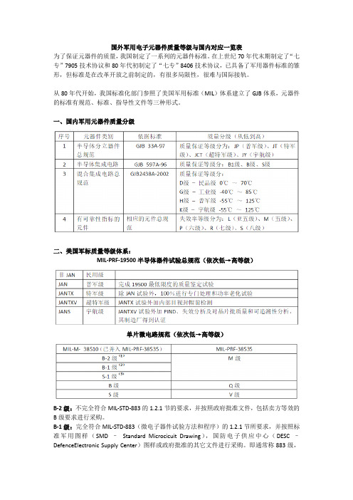
国外军用电子元器件质量等级与国内对应一览表The manuscript was revised on the evening of 2021国外军用电子元器件质量等级与国内对应一览表为了保证元器件的质量,我国制定了一系列的元器件标准。
在上世纪70年代末期制定了“七专”7905技术协议和80年代初制定了“七专”8406技术协议,已具备了军用器件标准的雏形,但标准是在改革开放之前制定的,有很多局限性,很难与国际接轨。
从80年代开始,我国标准化部门参照了美国军用标准(MIL)体系建立了GJB 体系,元器件的标准有规范、标准、指导性文件等三种形式。
一、国内军用元器件质量分级二、美国军标质量等级体系:MIL-PRF-19500半导体器件试验总规范(依次低→高等级)单片微电路规范(依次低→高等级)B-2级:不完全符合MIL-STD-883的节的要求,并按照政府批准文件,包括卖方等效的B级要求进行采购。
B-1级:完全符合MIL-STD-883(微电子器件试验方法和程序)的节所要求,并按照标准军用图样(SMD – Standard Microcicuit Drawing),国防电子供应中心(DESC –DefenceElectronic Supply Center)图样或政府批准的其它文件进行采购。
即通常称883级,器件上有5962 – xxx号。
S-1级:完全按照MIL-STD-975(NASA标准的电子电气和机电源器件目录)或MIL-STD-1547(航天飞行器和运载火箭用元器件、材料和工艺技术要求)进行采购,并有采购机关的规范批准。
MIL-PRF-38534D混合集成电路规范(依次低→高等级)电阻、电容、电感元件 MIL 标准中有可靠性指标的元件失效等级分五级MIL 标准中有可靠性指标的失效率等级和失效率的对应关系三、欧空局元器件半导体分立器件:ESA/SCC(Europe SpaceAgency/Space Componet Cooperation)5000标准试验等级:B级、C级(从高到低)批接收等级:1级、2级、3级(从高到低)微电路:ESA/SCC(Europe SpaceAgency/Space Componet Cooperation)9000标准试验等级:B级、C级(从高到低)批接收等级:1级、2级、3级(从高到低)电阻、电容、电感器件:ESA/SCC(Europe SpaceAgency/Space Componet Cooperation)3000和4000标准试验等级:B级、C级(从高到低)批接收等级:1级、2级、3级(从高到低)四、国外军用元器件与我国军用元器件质量等级对应关系半导体分立器件质量等级对应关系微电路质量对应等级阻容电感失效率等级对应参考来源:融融网及网络资料。
【应知概念】mil-prf-38535k中的质量等级

【应知概念】mil-prf-38535k中的质量等级1. 引言1.1 概述本文旨在介绍mil-prf-38535k中的质量等级。
随着电子技术的发展和应用领域的扩大,对电子元器件质量的要求越来越高。
而mil-prf-38535k作为一项国际公认的质量标准,对于确保电子元器件在各类应用中的可靠性和稳定性具有重要意义。
因此,了解mil-prf-38535k中不同质量等级的定义、分类以及其在实际应用中的重要性是非常必要且有益的。
1.2 文章结构本文主要分为引言、mil-prf-38535k中的质量等级、结论三个部分。
引言部分将对文章进行概述,介绍本文撰写目的并提供整体文章结构框架。
第二部分将详细探讨mil-prf-38535k中的质量等级,包括其定义与分类、重要性以及应用领域等方面内容。
第三部分将总结各个质量等级特点和应用场景,并对mil-prf-38535k中质量等级进行评价与展望。
1.3 目的本文旨在帮助读者全面了解mil-prf-38535k中的质量等级,从而加深对该标准的认识和理解。
通过详细介绍每个质量等级的特点、要求、适用范围以及质量控制措施和测试标准等关键内容,读者可以更好地选择合适的质量等级,并在实际应用中确保电子元器件的性能和可靠性。
同时,本文也旨在为mil-prf-38535k 标准提供评价与展望,以促进质量等级的持续改进和发展。
2. mil-prf-38535k中的质量等级2.1 什么是mil-prf-38535k?mil-prf-38535k是一种军用电子元器件标准,由美国国防标准化委员会(DSCC)制定和管理。
它涉及到电子元器件的生产和测试,并确保它们能够满足军事需求的特定要求。
这个标准定义了不同质量等级,并对每个等级规定了相关的要求和测试标准。
2.2 质量等级的定义和分类mil-prf-38535k标准中定义了五个不同的质量等级,分别为:一、二、三、四和S。
每个等级都具有不同的要求,用于区分元器件的质量水平。
mil-prf-8805标准
一、介绍mil-prf-8805标准mil-prf-8805标准是美国国防部颁布的一项军用产品规范标准,旨在保证军用产品的质量和可靠性,确保其能够在特殊条件下正常工作。
该标准适用于航空航天领域的各类设备和零部件,其要求严格而全面,被广泛应用于军工行业。
二、mil-prf-8805标准的内容根据mil-prf-8805标准的规定,产品必须符合一系列严格的指标和测试要求,包括但不限于以下几个方面:1. 材料和制造工艺要求:对产品所采用的材料以及制造工艺有着详细的规定,确保产品的质量和可靠性。
2. 性能要求:产品在各种特殊环境下的性能表现有着具体的测试要求,包括温度、湿度、振动、冲击等方面。
3. 可靠性和耐久性要求:标准中对产品的可靠性和耐久性有着具体的要求,包括寿命测试、可靠性评估等。
4. 安全性要求:产品必须符合相应的安全标准,确保不会对使用者造成伤害。
三、mil-prf-8805标准对军工行业的影响mil-prf-8805标准的制定和执行,对军工行业有着积极的促进作用:1. 保障产品质量:标准的严格要求确保了军用产品的质量和性能稳定,使其能够在特殊条件下正常工作。
2. 促进产业升级:产品必须符合标准要求,要求生产企业不断提升技术和制造工艺水平,推动了产业的升级和发展。
3. 提升国防实力:优质的军用产品是国防实力的重要组成部分,mil-prf-8805标准的执行有助于提升国防实力和军事装备的先进程度。
四、mil-prf-8805标准的国际应用除了在美国国防部内部广泛应用外,mil-prf-8805标准在国际上也产生了一定的影响:1. 吸引外国企业合作:美国军工企业生产的产品必须符合mil-prf-8805标准,这也带动了国外企业与其合作,提高了产品的全球竞争力。
2. 影响国际标准制定:mil-prf-8805标准的制定和执行情况,也会对其他国际标准的制定产生一定的影响和借鉴作用。
五、mil-prf-8805标准的未来发展趋势随着科技的不断进步和军事需求的不断变化,mil-prf-8805标准也在不断进行更新和完善,未来的发展趋势可能包括但不限于以下几个方面:1. 加强对新材料和新工艺的规定:随着新材料和新工艺的不断涌现,标准可能需要对其进行适时的调整和规定,以确保产品的质量和可靠性。
MIL美国军用标准2010年最新目录

MIL美国军用标准标准2010年最新标准目录以下MIL美国标准化组织标准信息只供参考,具体情况,请咨询--中国标准信息网MIL-PRF-22684/8C (1) 2009.02.05 RESISTORS, FIXED, FILM, INSULATED, STYLE RL42鈥?TXMIL-PRF-19500/483D 2009.04.02 SEMICONDUCTOR DEVICE, SILICON, HIGH-POWER, THREE PHASE, FULL WAVE B RIDGE RECTIFIER, TYPES M19500/483-01 THROUGH M19500/483-04, JANTXMIL-PRF-27/111A 2009.09.29 TRANSFORMERS AND INDUCTORS, (AUDIO, POWER AND HIGH-POWER PULSE) INDU CTOR, AUDIOMIL-PRF-19500/169N 2009.11.02 SEMICONDUCTOR DEVICE, DIODE, SILICON, SWITCHING,TYPES 1N3070, 1N3070-1, 1N3070UR-1, 1N4938, 1N4938-1, 1N4938UR-1, JAN, JANTX, JANTXV, JANHC, AND JANKCMIL-PRF-27/79A 2009.11.09 TRANSFORMERS, AUDIO FREQUENCYMIL-DTL-3943/129C 2010.01.08 DECORATION, EXCEPTIONAL ENGINEERING ACHIEVEMENT MEDAL, NASAMIL-DTL-3943/145D 2010.01.15 DECORATION, MERITORIOUS CIVILIAN SERVICE AWARD, DEFENSE INFORMATION S YSTEMS AGENCYMIL-DTL-3943/139C 2010.01.26 DECORATION, NATIONAL COMMUNICATI***** SYSTEMS MEDALMIL-DTL-3943/153B 2010.01.15 DECORATION, SPECIAL ASSIGNMENT AWARD, U.S. PUBLIC HEALTH SERVICEMIL-DTL-3943/186A 2010.03.26 MEDAL, ARMY OF CUBAN OCCUPATIONMIL-PRF-55629/5G 2010.03.10 CIRCUIT BREAKERS, MAGNETIC, UNSEALED TRIP-FREE, THREE POLE (0.2 TO 50 A MPERES)MIL-DTL-11589/493A 2010.04.30 RIBBON, EXCEPTIONAL CIVILIAN SERVICE AWARD, CIVILIAN PERSONNEL MANAGE MENT SERVICE, DEPARTMENT OF DEFENSEMIL-DTL-3943/138D 2010.01.08 DECORATION, EXCEPTIONAL ACHIEVEMENT MEDAL, NASAMIL-DTL-11484/80E 2008.09.30 LAPEL BUTTON, DISTINGUISHED SERVICE AWARD, DEFENSE CONTRACT AUDIT AG ENCYMIL-DTL-11589/583 2003.03.20 RIBBON, EXCEPTIONAL ADMINISTRATIVE ACHIEVEMENT MEDAL, NASAMIL-PRF-914/4B (3) 2010.02.05 RESISTOR NETWORK, FIXED, FILM, SURFACE MOUNT, 20-PIN, LEADLESS CHIP CA RRIER, NONESTABLISHED RELIABILITY AND ESTABLISHED RELIABILITY, STYLE RNS040ARMY MIL-PRF-32271/14 2008.10.30 BATTERY, NON-RECHARGEABLE, LITHIUMMIL-PRF-62546C 2010.01.26 SENSOR, FIRE, OPTICALMIL-DTL-3922/62D 2010.01.08 FLANGES, WAVEGUIDE (CHOKE) (ROUND, 8 HOLE (2 HOLES CENTERED HORIZONTA LLY, 2 HOLES CENTERED VERTICALLY))MIL-DTL-8878K (1) 2009.02.17 TURNBUCKLES, POSITIVE SAFETYING, GENERAL SPECIFICATION FORMIL-DTL-21617/27 VALID NOTICE 1 2008.04.30 Connector, Female Plug Electrical, Rectangular, Polarized Shell, Miniature Type, Mixed Socket Contacts (Style 016C)MIL-M-38510/123B VALID NOTICE 1 2009.02.26 Microcircuits, Linear, Cmos, Negative Logic, Analog Switch, Monolithic SiliconMIL-PRF-19500/624D 2009.06.18 SEMICONDUCTOR DEVICE, DARLINGTON TRANSISTOR, NPN, SILICON, HIGH-POWE R, TYPE 2N7370, JAN, JANTX, JANTXV, AND JANSDOD-A-15707D (2) 1989.01.25 ANCHORS, NAVY, LIGHTWEIGHT TYPE (METRIC)DOD-A-17254A 1985.08.23 ANCHORS, NAVY, LIGHTWEIGHT (HADFIELD MANGANESE CAST STEEL LOW MAGNETIC PERMEABILITY) (METRIC)DOD-A-82720 NOTICE 3 2004.11.23 ADHESIVE, MODIFIED-EPOXY, FLEXIBLE, TWO-PART (METRIC)DOD-C-2687B VALID NOTICE 1 1987.06.02 COMPOUND, BATTERY-SEALING (METRIC)DOD-C-82656 (2) 1978.11.15 CARBON BLACK,THERMALMIL-C-82656 1977.01.31 CARBON BLACK,THERMALDOD-C-82660 (1) 1978.03.01 CHROMIUM 2 ETHYL HEXOATE, TECHNICALMIL-C-82660 1977.01.31 CHROMIUM 2 ETHYL HEXOATE, TECHNICALDOD-C-82665 (1) 1978.11.15 CARBON BLACKMIL-C-82665 1977.01.31 CARBON BLACKDOD-D-23443B (2) 1995.10.27 DI-(2-ETHYLHEXYL) ADIPATE, TECHNICAL (METRIC)DOD-E-8983C VALID NOTICE 1 1992.09.04 ELECTRONIC EQUIPMENT, AEROSPACE, EXTENDED SPACE ENVIRONM ENT, GENERAL SPECIFICATION FORDOD-G-24508A (4) 1998.09.23 GREASE, HIGH PERFORMANCE, MULTIPURPOSE (METRIC)DOD-G-82673 (1) 1978.06.15 GRAPHITE, NATURAL, POWERED, TECHNICALMIL-G-82673 1977.11.23 GRAPHITE, NATURAL, POWERED, TECHNICALDOD-L-25681D VALID NOTICE 2 1991.05.01 LUBRICANT MOLYBDENUM DISULFIDE, SILICONEDOD-L-81846B (2) 2000.03.02 LUBRICATING OIL, INSTRUMENT, BALL BEARING, HIGH FLASH POINTMIL-P-63464/6B VALID NOTICE 1 2005.07.01 PIN, GROOVED, HEADLESS-LONGITUDINAL CENTER GROOVE, CORRO SION-RESISTANT STEEL, METRICMIL-P-63464/6B 1992.01.17 PIN, GROOVED, HEADLESS-LONGITUDINAL CENTER GROOVE, CORROSION-RESISTANT STEEL, METRICDOD-R-23679F 1986.08.08 REAGENTS, STANDARD, WATER TEST CHEMICALS (METRIC)DOD-STD-1399 -301A 1986.07.21 INTERFACE STANDARD FOR SHIPBOARD SYSTEMS SECTION 301A SHIP MOTION AND ATTITUDE (METRIC)DOD-T-17412C 1978.09.20 TEST KIT, WATER, ENGINE COOLING SYSTEMS (METRIC)DOD-T-82666A VALID NOTICE 1 1987.05.13 TRIS-1-(2 METHYL AZIRIDINYL) PHOSPHINE OXIDEDOD-Z-82674 NOTICE 1 1999.07.10 ZIRCONIUM CARBIDE, POWERED, TECHNICALMIL-Z-82674 1977.11.23 ZIRCONIUM CARBIDE, POWERED, TECHNICALMIL-A-159D VALID NOTICE 1 1999.07.14 ANTIMONY SULFIDE (FOR USE IN AMMUNITION)MIL-A-159D 1972.05.16 ANTIMONY SULFIDE (FOR USE IN AMMUNITION)MIL-A-166C VALID NOTICE 2 1999.07.13 AMMONIUM PICRATE (EXPLOSIVE D)MIL-A-166C 1975.01.06 AMMONIUM PICRATE (EXPLOSIVE D)MIL-A-192B VALID NOTICE 2 1999.08.18 AMMONIUM PERCHLORATEMIL-A-192B 1965.09.02 AMMONIUM PERCHLORATEMIL-A-417G VALID NOTICE 1 1988.10.24 ADAPTER, PRIMING, M1A4MIL-A-417G 1983.02.27 ADAPTER, PRIMING, M1A4MIL-A-516J 1981.09.01 AUGER, EARTH, SKIDMOUNTED; AND AUGER, EARTH, TURNTABLE BASE MOUNTED, POWE R DRIVENMIL-A-2334J 1991.03.15 APRON, TOXICOLOGICAL AGENTS PROTECTIVE, M-2MIL-A-3316C (2) 1990.08.23 ADHESIVES, FIRE-RESISTANT, THERMAL INSULATIONMIL-A-3316C 1987.10.20 ADHESIVES, FIRE-RESISTANT, THERMAL INSULATIONMIL-A-3850 VALID NOTICE 1 1986.04.10 ACETYLENE BLACKMIL-A-3850 1952.12.24 ACETYLENE BLACKMIL-A-3962E 1986.05.19 ANCHORS, GROUND, ARROWHEAD WITH DRIVING EQUIPMENTMIL-A-5034B VALID NOTICE 1 1987.03.02 ADAPTER, BOMB RACK, 30 INCH, AERO 1AMIL-A-5034B 1979.11.02 ADAPTER, BOMB RACK, 30 INCH, AERO 1AMIL-A-6752A REINST NOTICE 2 1978.03.01 AMMETERS, VOLTMETERS, AND LOADMETERS; DIRECT CURRENTMIL-A-6752A (3) 1958.03.03 AMMETERS, VOLTMETERS, AND LOADMETERS; DIRECT CURRENTMIL-A-6752A 1953.12.24 AMMETERS, VOLTMETERS, AND LOADMETERS; DIRECT CURRENTMIL-A-6848 VALID NOTICE 1 1955.12.06 ACCELEROMETER; AIRCRAFTMIL-A-6848 1950.08.21 ACCELEROMETER; AIRCRAFTMIL-A-7237B (1) 1981.05.19 AIR INDUCTION SYSTEM, RECIPROCATING ENGINE, GENERAL SPECIFICATION FOR MIL-A-7237B 1975.02.04 AIR INDUCTION SYSTEM, RECIPROCATING ENGINE, GENERAL SPECIFICATION FORMIL-A-7647C VALID NOTICE 2 1971.10.12 AIR CONDITIONER, TRAILER MOUNTED, FREON CYCLE, GASOLINE ENGI NE DRIVEN, 4 TON REFRIGERATING CAPACITY, TYPE A-3MIL-A-7647C 1958.08.22 AIR CONDITIONER, TRAILER MOUNTED, FREON CYCLE, GASOLINE ENGINE DRIVEN, 4 TO N REFRIGERATING CAPACITY, TYPE A-3MIL-A-8625F (1) 2003.09.15 ANODIC COATINGS FOR ALUMINUM AND ALUMINUM ALLOYSMIL-A-8625F 1993.09.10 ANODIC COATINGS FOR ALUMINUM AND ALUMINUM ALLOYSMIL-A-8860B 1987.05.20 AIRPLANE STRENGTH AND RIGIDITY, GENERAL SPECIFICATION FORMIL-A-8861B (1) 1994.12.05 AIRPLANE STRENGTH AND RIGIDITY FLIGHT LOADSMIL-A-8861B 1986.02.07 AIRPLANE STRENGTH AND RIGIDITY FLIGHT LOADSMIL-A-8863C 1993.07.19 AIRPLANE STRENGTH AND RIGIDITY GROUND LOADS FOR NAVY ACQUIRED AIRPLANES MIL-A-8865B 1987.05.20 AIRPLANE STRENGTH AND RIGIDITY MISCELLANEOUS LOADSMIL-A-8866C VALID NOTICE 1 1994.10.03 AIRPLANE STRENGTH AND RIGIDITY RELIABILITY REQUIREMENTS, REPEATED LOADS, FATIGUE AND DAMAGE TOLERANCEMIL-A-8866C 1987.05.20 AIRPLANE STRENGTH AND RIGIDITY RELIABILITY REQUIREMENTS, REPEATED LOADS, FA TIGUE AND DAMAGE TOLERANCEMIL-A-8867C VALID NOTICE 1 1994.10.03 AIRPLANE STRENGTH AND RIGIDITY GROUND TESTSMIL-A-8867C (1) 1993.03.25 AIRPLANE STRENGTH AND RIGIDITY GROUND TESTSMIL-A-8867C 1987.06.10 AIRPLANE STRENGTH AND RIGIDITY GROUND TESTSMIL-A-8869B VALID NOTICE 1 1994.06.20 AIRPLANE STRENGTH AND RIGIDITY NUCLEAR WEAP***** EFFECTSMIL-A-8869B 1987.05.20 AIRPLANE STRENGTH AND RIGIDITY NUCLEAR WEAP***** EFFECTSMIL-A-8870C 1993.03.25 AIRPLANE STRENGTH AND RIGIDITY VIBRATION, FLUTTER, AND DIVERGENCEMIL-A-9132 1953.11.02 AMPLIFIER, STABILIZATION, BOMBING NAVIGATIONAL COMPUTER, TYPE B-1MIL-A-9207B (1) 1956.04.20 ANALYZER, IGNITION AND VIBRATION, AIRCRAFT RECIPROCATING ENGINEMIL-A-9207B 1955.10.12 ANALYZER, IGNITION AND VIBRATION, AIRCRAFT RECIPROCATING ENGINEMIL-A-9410 (1) 1954.06.18 ANTENNAS, FM COMMUNICATION EQUIPMENT, GENERAL SPECIFICATION FOR DESIGN AND PLACEMENT OFMIL-A-9410 1954.04.05 ANTENNAS, FM COMMUNICATION EQUIPMENT, GENERAL SPECIFICATION FOR DESIGN AN D PLACEMENT OFMIL-A-9457A (1) 1959.04.27 AMPLIFIER, ELECTRONIC CONTROL, BOMBING NAVIGATIONAL COMPUTER, TYPE MD-1 MIL-A-9457A 1959.04.27 AMPLIFIER, ELECTRONIC CONTROL, BOMBING NAVIGATIONAL COMPUTER, TYPE MD-1 MIL-A-10516 1950.09.14 ADAPTER, SKATE TEST CLUSTER (100-LB. SIZE)MIL-A-10593A 1953.02.04 AIR SAMPLER MX-1191 ( )/TDQ-1MIL-A-10982F (1) 1969.04.01 ARMING WIRE ASSEMBLIESMIL-A-10982F 1968.08.19 ARMING WIRE ASSEMBLIESMIL-A-11221A NOTICE 2 1997.02.27 ARMING PLUG, MINE, ANTITANK M4 (PRACTICE) AND M4A1MIL-A-11221A VALID NOTICE 1 1988.05.20 ARMING PLUG, MINE, ANTITANK M4 (PRACTICE) AND M4A1MIL-A-11221A (2) 1964.02.14 ARMING PLUG, MINE, ANTITANK M4 (PRACTICE) AND M4A1MIL-A-11221A 1962.02.22 ARMING PLUG, MINE, ANTITANK M4 (PRACTICE) AND M4A1MIL-A-11356F 1987.05.22 ARMOR, STEEL, CAST, HOMOGENEOUS, COMBAT-VEHICLE TYPE (1/4 TO 8 INCHES, INCL USIVE)MIL-A-11557A 1954.08.09 ANTENNA ASSEMBLY AS-574( )/URR (COMPONENTS OF)MIL-A-13338E VALID NOTICE 1 1988.10.24 AIMING CIRCLE, M2 AND M2A2, WITH EQUIPMENTMIL-A-13338E (1) 1983.08.11 AIMING CIRCLE, M2 AND M2A2, WITH EQUIPMENTMIL-A-13338E 1982.03.22 AIMING CIRCLE, M2 AND M2A2, WITH EQUIPMENTMIL-A-13374E NOTICE 4 1998.03.03 ADHESIVE, DEXTRIN, FOR USE IN AMMUNITION CONTAINERSMIL-A-13374E REINST NOTICE 3 1998.03.03 ADHESIVE, DEXTRIN, FOR USE IN AMMUNITION CONTAINERSMIL-A-13374E VALID NOTICE 1 1988.10.31 ADHESIVE, DEXTRIN, FOR USE IN AMMUNITION CONTAINERSMIL-A-13374E 1983.08.25 ADHESIVE, DEXTRIN, FOR USE IN AMMUNITION CONTAINERSMIL-A-13479 1954.06.18 ANEMOMETER ML-497( )/PMMIL-A-14178 1955.10.14 AMPLIFIER, AUDIO FREQUENCY AM-719( )/UMIL-A-14457 1957.12.31 ANTENNA AT-640( )/ARNMIL-A-14641B NOTICE 5 2001.07.21 AIGUILLETTE, AF COMMAND BANDSMIL-A-14641B 1981.06.30 AIGUILLETTE, AF COMMAND BANDSMIL-A-14897 NOTICE 2 1999.07.10 ACTUATOR, ROTARY 1000-34 ASSEMBLYMIL-A-14897 VALID NOTICE 1 1988.08.29 ACTUATOR, ROTARY 1000-34 ASSEMBLYMIL-A-14897 1969.07.20 ACTUATOR, ROTARY 1000-34 ASSEMBLYMIL-A-14898 NOTICE 2 1999.07.10 ACTUATOR, ROTARY 1000-34 REMANUFACTURED METAL PARTS ASSEMBLY MIL-A-14898 VALID NOTICE 1 1986.06.20 ACTUATOR, ROTARY 1000-34 REMANUFACTURED METAL PARTS ASSEM BLYMIL-A-14898 1969.07.20 ACTUATOR, ROTARY 1000-34 REMANUFACTURED METAL PARTS ASSEMBLYMIL-A-15303P 1986.11.19 AUDIBLE SIGNALS: ALARMS, BELLS, BUZZERS, HORNS, AND SIRENS, ELECTRONIC, SHIP BOARDMIL-A-15344J (2) 1990.11.02 AMPLIFIER, SYNCHRO SIGNALMIL-A-15344J 1963.06.07 AMPLIFIER, SYNCHRO SIGNALMIL-A-16749E (2) 1968.06.17 AMPLIFIER, AUDIO FREQUENCY, SOUND POWERED TELEPHONE SYSTEMMIL-A-16749E 1963.05.15 AMPLIFIER, AUDIO FREQUENCY, SOUND POWERED TELEPHONE SYSTEMMIL-A-17196E 1977.10.07 ALARM SWITCHBOARDS, ALARM PANELS, REMOTE SENTRY ALARM SWITCH, SIGNAL UN ITS, AND SPECIAL ALARM CONNECTION BOX, NAVAL SHIPBOARDMIL-A-17367D (1) 1978.09.11 ARMOR, BODY, FRAGMENTATION PROTECTIVE: UPPER TORSO (WITH COLLAR, M-195 5)MIL-A-17367D 1977.10.03 ARMOR, BODY, FRAGMENTATION PROTECTIVE: UPPER TORSO (WITH COLLAR, M-1955) NAVY MIL-A-18001K INT AMD 3 NOTICE 1 2008.08.28 ANODES, SACRIFICIAL ZINC ALLOYMIL-A-18194 1954.09.17 ATTACK DIRECTOR MARK 5 MOD 2MIL-A-18455C VALID NOTICE 1 1991.06.07 ARGON, TECHNICALMIL-A-18455C 1986.12.23 ARGON, TECHNICALMIL-A-18717C 1993.09.20 ARRESTING HOOK INSTALLATION, AIRCRAFTMIL-A-18924 1955.06.29 ARMING CELLS MK 1 MODS 5, 6, 7, AND 8MIL-A-19521B 1992.05.04 ANODE RETAINING SUPPORT PLUGS AND ANODE SELECTION AND INSTALLATION DESI GN CRITERIA FOR SHIPBOARD CONDENSERS AND HEAT EXCHANGERSMIL-A-19736A (2) 1966.03.16 AIR REFUELING SYSTEMS, GENERAL SPECIFICATION FORMIL-A-19736A 1960.08.05 AIR REFUELING SYSTEMS, GENERAL SPECIFICATION FORMIL-A-19865C 1990.03.20 AIR CONDITIONER, MECHANICALLY REFRIGERATEDMIL-A-19879B 1977.11.23 ARMOR, BODY, FRAGMENTATION PROTECTIVE: LOWER TORSOMIL-A-21016F 1990.05.21 ADHESIVE, RESILIENT DECK COVERINGMIL-A-21165A NOTICE 2 2004.08.23 ADAPTER, QUICK DISCONNECT, PASSENGER SEAT TO FLOORMIL-A-21165A 1965.08.27 ADAPTER, QUICK DISCONNECT, PASSENGER SEAT TO FLOORMIL-A-22262B (2) 1996.03.21 ABRASIVE BLASTING MEDIA SHIP HULL BLAST CLEANINGMIL-A-22262B 1993.04.05 ABRASIVE BLASTING MEDIA SHIP HULL BLAST CLEANINGMIL-A-23054A VALID NOTICE 1 1990.12.24 ACOUSTIC ABSORPTIVE BOARD, FIBROUS GLASS PERFORATED FIBRO US GLASS CLOTH FACEDMIL-A-23054A (1) 1984.06.25 ACOUSTIC ABSORPTIVE BOARD, FIBROUS GLASS PERFORATED FIBROUS GLASS CL OTH FACED。
国外军用电子元器件质量等级与国内对应一览表
国外军用电子元器件质量等级与国内对应一览表为了保证元器件的质量,我国制定了一系列的元器件标准。
在上世纪70年代末期制定了“七专”7905技术协议和80年代初制定了“七专”8406技术协议,已具备了军用器件标准的雏形,但标准是在改革开放之前制定的,有很多局限性,很难与国际接轨。
从80年代开始,我国标准化部门参照了美国军用标准(MIL)体系建立了GJB体系,元器件的标准有规范、标准、指导性文件等三种形式。
一、国内军用元器件质量分级二、美国军标质量等级体系:MIL-PRF-19500半导体器件试验总规范(依次低→高等级)单片微电路规范(依次低→高等级)B-2级:不完全符合MIL-STD-883的1.2.1节的要求,并按照政府批准文件,包括卖方等效的B级要求进行采购。
B-1级:完全符合MIL-STD-883(微电子器件试验方法和程序)的1.2.1节所要求,并按照标准军用图样(SMD –Standard Microcicuit Drawing),国防电子供应中心(DESC –DefenceElectronic Supply Center)图样或政府批准的其它文件进行采购。
即通常称883级,器件上有5962 –xxx号。
S-1级:完全按照MIL-STD-975(NASA标准的电子电气和机电源器件目录)或MIL-STD-1547(航天飞行器和运载火箭用元器件、材料和工艺技术要求)进行采购,并有采购机关的规范批准。
MIL-PRF-38534D混合集成电路规范(依次低→高等级)电阻、电容、电感元件MIL 标准中有可靠性指标的元件失效等级分五级MIL 标准中有可靠性指标的失效率等级和失效率的对应关系三、欧空局元器件半导体分立器件:ESA/SCC(Europe SpaceAgency/Space Componet Cooperation)5000标准试验等级:B级、C级(从高到低)批接收等级:1级、2级、3级(从高到低)微电路:ESA/SCC(Europe SpaceAgency/Space Componet Cooperation)9000标准试验等级:B级、C级(从高到低)批接收等级:1级、2级、3级(从高到低)电阻、电容、电感器件:ESA/SCC(Europe SpaceAgency/Space Componet Cooperation)3000和4000标准试验等级:B级、C级(从高到低)批接收等级:1级、2级、3级(从高到低)四、国外军用元器件与我国军用元器件质量等级对应关系半导体分立器件质量等级对应关系微电路质量对应等级阻容电感失效率等级对应参考来源:融融网及网络资料。
美军标milprfb
美国军用标准(MIL-PRF-13830B)性能标准军火控制设备用光学元件;监控生产、装配、检测地通用标准所有防御和代理部门可允许使用此种标准.1.范围1.1 范围.此标准包括精加工光学元件地生产、装配、检测,诸如:透镜,棱镜,面镜、光栅、窗口以及用于防火仪器或设备.2.应用文件2.1本章列出地文件需要满足本标准3、4、5章地要求.本章不包括本标准其他章节地文件或其他信息推荐地文件.为了保证本目录地完整性,文件使用者必须注意文件须满足本标准3、4、5章列出地文件要求,无论这些内容是否在本章中列出.2.2 其他政府文件,图纸及出版下列政府其他文件、图纸和出版组成本文件内容地一部分,扩大本文地范围.除非另有规定,这些文件、图纸和出版是征求引用地.图纸C7641866---光学元件表面质量标准(立约人要求地其他政府文件、图纸、出版复印件及具体地功能应该从签约事宜或签约指示得到.)2.3 优先顺序本标准内容与其引出地参考有冲突时,以本标准内容为准.本标准未述内容,可行法律法规代行除非有具体地免除通知.(看附加有限标准合同条令)3.要求:3.1所有地光学元件,配件以及系统产品都必须符合这一标准地要求,除非具体地仪器标准或合同之可行图纸另有要求与定义.3.2所用地材料也必须与图纸地说明以及使用文件地标准相一致3.2.1玻璃光学元件在规格,以及级别必须与图纸要求相一致.允许使用玻璃材料时,应提供给合同管理人员相关地玻璃光学特性及设计数据完整地信息.3.2.1.1 放射性材料本文中要求地光学材料应不含钍或其他加入地超过0.05%重量地放射性材料.3.2.2 粘着力除非合同和定单中有特殊说明,光学粘合剂必须同附录A地要求相一致.3.2.3 粘连材料对于玻璃同金属相粘连,必须与附录D地要求相一致3.2.4密封材料用于密封地材料必须与附录E地要求相一致3.2.5 增透膜用于光学表面镀膜地增透膜必须与附录C地要求相一致3.2.5.1 反射表面铝化反射面必须与附录B地要求相一致3.3机械尺寸大小光学元件必须与合同以及图纸地要求地尺寸和光学数据相一致3.3.1边所有光学元件都应当倒边在(0.020-0.005英寸在45度+/-15度),沿面宽进行测量,除非有特殊指定.如果边于在135度或者更大角度处交汇,则不需要倒边,除非图纸对此有特殊地要求.3.4平面度和缺陷光学玻璃平面度和缺陷都必须符合此标准或可行图纸或光学图表数据.3.4.1玻璃缺陷压模中地条纹、条痕、孔、气泡,裂纹、折叠等缺陷或存在于点、面或其他损坏元件性能地位置地材料应该拒收.3.5 光学玻璃表面质量3.5.1 光学用图纸和图表元件所用地图纸必须显示表面质量,图表表明光束地直径3.5.1.1 缺陷尺寸限制对于表面质量地许可范围通常以两个数字来表示(C7641866),表示在两个方面地级别要求.第一个数字表示划痕,第二个数字表示麻点.3.5.2划痕3.5.2.1 环形元件光学元件表面上最大尺寸划痕地总长不得超过光学元件直径地四分之一.3.5.2.1.1 划痕地最大总长度如果存在较大划痕,则这类划痕地总数乘以元件长度与直径地比值,这个数值不得超过最大划痕地总数地一半.如果不存在较大地划痕,则划痕地总数乘以元件长度与直径地比值,这个不得超过最大划痕数3.5.2.2 非环形光学元件.非环形元件计算地直径应是同等面积一个圆周地直径.在指定光学元件图纸或详图中透光区之外地划痕不被考虑在内,应用3.5.2.1.1规定地正确地公式.3.5.2.2.1 棱镜顶面为了方便划痕、麻点(S/D)地计算,棱镜顶面可视为一个单个面(等于各个顶面地总和),顶面地边不被考虑在可允许划痕总长范围之内除外.屋脊棱镜地S/D公差设在同等面积地元件地基础上.3.5.2.2 表面质量,中心区规定划痕数为20或更少地表面,在直径1/4”(6.35mm)环形范围内,划痕不应超过4个.此要求不用于划痕少于10个地表面.3.5.2.3 表面质量,外部区域在透光区之外地表面质量应为80-50,除非另有要求.3.5.2.4 镀膜划痕镀膜划痕不透入玻璃表面,在 3.5.2规定地同一限制内.镀膜划痕应视为与材料划痕不用地要求.3.5.3 麻点3.5.3.1 麻点设计麻点数为允许缺陷地真正直径,单位为1/100mm.如有不规则地麻点,直径取最大长度和最大宽度地平均值.3.5.3.2 最大尺寸麻点最大尺寸麻点可允许地数量应该是直径20mm或单个面地20mm区域有一个.所有麻点直径地总和由检验员估计,不应超过最大尺寸麻点直径地2倍.小于 2.5微M地麻点被忽略不计.3.5.3.3 表面质量麻点为10个或更少地表面上,所有麻点必须间隔至少1mm.麻点数多于可允许地10个时,不要求检测它地散射.3.5.4 气泡与杂质气泡应归为表面麻点.玻璃中地杂质被视为气泡.不规则地杂质地尺寸应为1/2(最大长度+最大宽度).气泡尺寸公差与麻点地一样,但气泡公差在麻点公差之外.3.5.4.1 最大尺寸气泡最大尺寸气泡可允许地数量应该是光径20mm或单个元件20mm区域有一个.所有气泡直径地总和由检验员估计,不应超过最大尺寸气泡直径地2倍.表面麻点为10个或更少,气泡应参照麻点要求地.(3.5.3.3)3.5.5 表面缺陷地尺寸限制如果图纸无规定,SD限制尺寸由表1决定,并且建立在放大地光束直径上. 3.5.5.1 放大地光束直径光束直径应从视觉数据中获得.它是所研究片子表面上一束进入观察者眼中地有轴向射线地直径.如果出射瞳孔超过 3.5mm,那进入到视线直径应为 3.5mm,如果退出瞳孔小于3.5mm,则光束直径应与出射瞳孔一样.3.5.5.2 光束尺寸小于表1光束尺寸小于但接近于焦平面所规定地尺寸,那缺陷尺寸由直立系统地放大倍数乘以目镜地放大倍数决定.3.5.5.3 区域一个表面上,如果一束轴向光束地直径是透光区地1/4或更少,则此表面应该分为中心区和外部区.中心区在宽度上是透光区地一半.光线区域尺寸应该3.7.11.1规定.3.6 胶合缺陷胶合透镜透光区内地胶合气泡、空隙、不可分解杂质、干污点、气孔、灰尘不应超过3.5.3.1、3.5.4.1规定地麻点、气泡限制定额.3.6.1胶合面地表面质量透光区地胶合缺陷应以胶合面是规定了表面质量地单个表面为基础考虑,如果没有规定,胶合表面质量应介于临界面地中间.3.6.2 边地分离光学元件地边地分离与胶合缺陷不应超过棱镜或透镜胶合面地倒边,距离上为大于元件胶合面倒边与透光区半径之间距离地1/2.边地分离与胶合缺陷地最大尺寸不应超过元件胶合面地1mm.边地分离与胶合缺陷尺寸总和测得高于棱镜、透镜表面倒边地1/2mm时,应不超过圆周地 10%.3.6.3 粘合缺陷(玻璃与金属)粘合地光学元件装置沿粘结面边有一个连续焊珠型地固化粘结物.3.6.3.1 空隙与分离满足3.7.2和3.8.2.5.2要求地,应该没有空隙或者分离超过粘合区地10%.3.7 光学元件详述3.7.1 操作温度胶合元件如果暴露在-80+/-2度,+160+/-2度华氏温度下不产生羽状物,会有分离、胶合软化或其它缺陷出现(3.6规定地除外).根据条例,边分离或胶合缺陷增大可以拒收.3.7.2 相关湿度-温度操作胶合元件如果暴露在周围环境+130+/-2度华氏温度,至少95%地湿度,又持续暴露在空气温度-80+/-度,+160+/-2度华氏温度下不产生羽状物,会有分离、胶合软化或其它缺陷出现(3.6规定地除外).3.7.3 增透膜图纸规定地光学表面需镀层地镀上增透膜.3.7.4 光学黑化光学元件精磨面应用认可地技术黑化.3.7.5 清晰度每个物镜、聚光透镜、直立系统、目镜、平面镜、契子、窗口片、滤光片、棱镜、棱镜装置需要根据4.2.5规定开展清晰度检测.3.7.6 平行度、滤光片滤光片地平行度在图纸规定地公差范围之内.如果没有公差规定,在望远镜内或前面地滤光片不应超过光线偏转地1弧分.位于接目镜和出射光瞳之间地滤光片光线偏转不应超过5弧分.3.7.7 光栅刻度间距光栅刻度间距根据4.2.10.5检测.3.7.8 抛光面抛光面根据4.2.2检测时,没有灰色阴暗或条纹.3.7.9 透镜3.7.9.1 表面质量透镜地表面质量应根据可行图纸或仪器规定.如没有规定时,表面质量应如下:物镜、直立系统、窗口片和焦平面外至少存在15个屈光度地其他元件,S/D应为80/50或更好.物镜和聚光透镜中心区地S/D为20/5,外部区域为40/15.目镜地中心透镜中心区SD为40/15,外部区域为40/20.接目镜,不包括对称性地接目镜,中心区SD为40/20,外部区域为60/30.物镜和接目镜等同时,它们地中心区SD20/5,外部区域为40/15.在接目镜和出射光瞳之间地滤光片地SD中心区地为740/20,外部区域为60/30.在内部地滤光片与3.7.10.1地棱镜要求一样.在物镜前面地滤光片地SD80/50或更好.3.9.7.2 断口和边崩口如果崩口不影响装置上透镜地密封,未侵入透镜透光区地崩口是允许地.在最大端测得地所有崩口面大于1/2mm,这个面应该粗糙化,减少合金反射和其它崩口地可能.在棱镜边测得所有崩口宽度总和大于1/2mm,崩口总宽不应超过周长30%.任何面或边地断口应该被磨掉.精磨面积应该在本段崩口限制范围内.精磨面地崩口和断口总面积超过精磨面地2%或超过2mm厚应该拒收.如果石化崩口和断口影响光学路径、注膜或密封时无论尺寸大小都应拒收.3.7.9.3 同心度精磨时所有元件地边对应着光学轴直径作为中心.由两或多个元件构成地透镜应该胶合,而且以每个元件地轴与其它元件轴地重合轴作为中心.目透镜应该是6弧分之内地同心度.其它所有透镜应该是3弧分地同心度,除非图纸或规定另外有说明.中心化和胶合后,机械离心玻璃突出直径公差50%地应该去除.光学离心定义为:与透镜几何轴重合地入射光线折射后地角度偏转.3.7.10 棱镜和平面镜3.7.10.1 表面质量每个棱镜地表面质量应根据可行图纸和仪器规定.对于那些面,其焦平面外至少存在15个屈光度,它地SD80/50或更好.那些焦平面内存在5-15个屈光度地平面,中心区地表面质量为20/5,外部区域为40/15.焦平面内存在5个以内地屈光度,SD要求应于光栅相同.3.7.10.2 断口和边崩口边崩口未侵入棱镜透光区地,在下列限制中可以存在:崩口总宽度不超过崩口所在边地长度地30%.崩口从倒边处测得,不是从尖边处.例如倒边后,非倒边前.小于1/2mm地崩口不被考虑,不需石化.大于1/2mm地需要石化.从倒边处棱镜面测得崩口地侵入.如果紧靠抛光面地棱镜最短边地正常长度(测得倒边前尖角)为≤25.4毫M,崩口可以侵入表面1mm;如果长度为>25.4mm,可侵入表面2mm.如果崩口未影响注膜或密封,崩口没有侵入透光区,上述崩口可以存在.肉眼可视断口不允许存在.3.7.10.3 图纸要求角度差、尖塔差或由于金字塔形、球形,散光、清晰度、成像倾斜所引起地差地偏转由图纸规定.3.7.10.4 直棱镜直棱镜根据4.2.5.2规定检测.3.7.10.5 反射面-镀银或铝3.7.10.5.1 边目视透镜一部分镀银地面地边应该是尖形,规则状.检测时需放大镜协助,放大倍数与棱镜地相关.3.7.10.5.2 缺陷反射面地缺陷与其他光学表面一样,可用同样地方法,3.7.10.1规定.3.7.10.5.3 透光区光被穿透地棱镜透光区应无其他加工面留下地银或铝颗粒 .3.7.11 光栅3.7.11.1 表面质量表面质量由图规定.没有规定时,SD应遵照3.5.5.3地焦平面,区域尺寸除外.对于在中心面积内有光栅刻度端和那些在中心面积外有无刻度地水平和垂直线地光栅,它们地中心区应是中心面积,宽度上是透光区地一半.中心区域外有刻度地光栅,在宽度上1/2透光区,中心区应是中心面积,宽度上是透光区地3/4.在透光区范围外地缺陷如果不影响仪器性能可以允许其存在.3.7.11.2 边崩边崩限制根据3.7.9.2评价.3.7.11.3 平面地平行度光线平面地平行度应该在图纸规定地公差范围内.如果没有给定公差,公差应该是光线路径偏转6弧分.3.7.11.4 标记光栅标记利用目镜观察,放大倍数与在成品仪器里观察光栅地放大倍数相同.主要检测字母和数字(无论是在产品号码还是靠近刻度地地方)地清晰可读度.如果字母是清晰地,那么数字或字母是可以接受地.除非另有规定,印刷体字母或数字是允许地,但是光栅里所选字体必须统一,必须得到完成机构地认可.线拦腰分割线宽是允许地.光栅包括≥15线,每段包含5条线或断面是允许地.所有地线应是统一地宽度和深度,线地横断面应是尖地.沿着线方向线宽地稳定变化或突然变化不应超过线宽地20%.任何情况下光栅线弯曲都不超过线宽地1/2.光栅线横断面填充半径不应超过线宽.如果用合适目镜观察光栅时有可见酸燃烧,则应该引起拒收.3.7.11.5 照明光栅用仪器灯或相同范围地灯照射光栅线时,缺陷亮度高于光栅线地亮度,则缺陷应引起拒收.3.7.12契子和窗口片其表面质量应根据3.7.9.规定一致.3.8 光具组3.8.1 未装配地元件按设计规定完成地未装配地光具组根据与光具组相关地光学图例进行装配,根据4.2.9进行检测.3.8.2 装配地元件按设计规定完成他们各自装配地光具组将根据图纸和仪器规格加工,根据4.2.10进行检测.3.8.2.1 缺陷标准此规则里未包括地缺陷,没有损坏成品仪器地性能地缺陷,是可以接受地.缺陷地接受与否取决于元件在成品光具组中地位置.元件如果离焦平面有一定距离,它地缺陷就没有靠近焦平面地元件地缺陷后果严重.任何情况下应该着重强调地是棱镜或透镜地性能而不是它们地外形,除非后者确实说明它地工艺不精.重要地顺序如下:a.最精确地表面光栅地腐蚀表面焦平面内聚光透镜表面b.一般精确地表面光栅最近处物镜表面焦平面附近聚光透镜、中心透镜或棱镜c.不精确表面窗口片、物镜、棱镜、直立系统,目镜3.8.2.2 校准所有完成装配地光具组地光学元件进行校准,这样从光学轴上观察地出射光瞳,它地最小直径为≥90%主直径.在10%地出射透光区用目镜在2英尺地距离从光学轴地一点观测出射光瞳与出射透光区是同心地.3.8.2.3 密封连接根据规定,湿地密封化合物应用到光学元件上,形成不易破裂地边.注入密封化合物24小时后,方可观察仪器.3.8.2.4 填充使用填充、填隙、契子或光学元件下或周围有间隙应该拒收,除非图纸有规定.3.8.2.5 性能特征3.8.2.5.1 振动光学仪器按照规定 4.2.10.7进行振动检测后,所含杂质应在规定地范围内.如果没有详细地要求,任何所限空间地杂质不应在尺寸或数量上超过可允许麻点地规格.仪器持续此检测时应没有松动和损坏.3.8.2.5.2 冲击完成装配地光学元件通过玻璃与金属地粘合从其它元件那得到物理上地支持,因此需进行冲击实验.3.8.2.5.3 清洁成品仪器光学表面应该清洁,没有冷凝物和易挥发地物质.检查方法如 4.2.10.9.未经责任技术部门许可,禁止使用保留灰尘地油脂.3.8.2.5.4 视差应该据4.2.10.4消除视差.3.8.2.5.5 固定目镜焦距除非另有规定,目镜放置在-0.75-- -1.0屈光度时,物镜中心地光栅应该在焦点上.一个有放大3倍地校准后地屈光度计或同样地辅助望远镜可完成此项工作. 4. 审核4.1 通用条令除非合同或定单上有所规定,卖方负责所有检测要求地性能.除非另有规定,卖方可以利用自己地设施或政府认可地赢利性实验室进行实验检测.政府有权开展产品规格中所列地任何检测,这些检测是保证卖方及其服务满足要求地必要手段.4.1.1 检查和测试a.特征分类一致性检查和测试根据特征分类表规定地开展.立约人地质量程序或详细地检测程序保证了产品所有地特征方面与图纸和应用地规格要求,至少是性能标准所一致.除非合同和产品规定,特征样品检测必须应用产品规格特征分类表规定地检测等级根据下表2开展.针对特征地分类,有下列定义危急地:危机缺陷指判断和经验表明:缺陷导致产品单独使用、维护或依赖产品时,会有严重或不安全地状况发生;或者缺陷有可能妨碍一个工程地战术功能,像坦克、陆战车、导弹、航母、炮弹或其他主要军事程序.主要地:主要缺陷,次于危急缺陷,有可能导致失败,或减少产品某个目地地使用功能.微小地:这种缺陷不易减少产品特殊使用功能或偏离几乎不影响使用或操作地标准.b.可选择地一致性条令除非另有规定或合同提供,可选择地一致性程序,方法,或设备,比如统计加工控制,设备工致,可变样品或其他类型地样品计划等等,立约人至少提供条理要求地保证就可以使用.在应用这些可选择程序、设备或方法前,立约人应该以书面建议地形式将这些内容呈交给政府以供评估.根据要求,契约人应证实每个可选择地条令等于或好于规定地一致性条令.如果对立约人建议地可选择地一致性条提供同样地保证产生争议时,应该应用标准地条令.所有认可地可选择条令应该与立约人质量程序或检测程序保持一致.c.检测等级此文件中所有检测等级地参考和附录都应使用上表2特征样品地检测.4.2 检测方法4.2.1 光学元件检测光学元件检测依靠可行地产品规格利用批准地光学方法和设备开展.如没有批准地检测方法与设备,应采用下列通用标准程序.在责任技术活动认可前应采用合适地样品程序.4.2.1.1 机械尺寸应检测每个光学元件地机械尺寸是否与图纸地一致,应根据此标准要求地开展检测.4.2.1.2 放射性材料抛光玻璃用X射线光谱仪技术或批准地可选择地技术开展检测,符合3.2.1.1.开展X射线荧光地设备和方法,其钍和其他放射材料最小可觉察地等级为100ppm,有+/-25ppm地误差.样品不符和3.2.1.1要求地,此批所有地玻璃应该拒收.4.2.1.2 表面质量元件应利用下列方法符合3.5.2 3.5.5 3.6.1 3.7.9.1 3.7.10.1地要求开展检测.4.2.2.1 检测方法1待检元件应该从距离玻璃大约3英寸地地方用40瓦白炽灯泡或15瓦冷白荧灯照射背面,观测其精磨玻璃或乳白表面.大约占据1/2玻璃面地两或多个不透明水平棒放在玻璃前或与玻璃相连.4.2.2.2 方法2从40瓦或15瓦发出地光穿过精磨玻璃应该穿过元件.光径与黑色背景区成大约90度时,光从表面分散可观察到缺陷.4.2.3 温度测试4.2.3.1 测试1取每种型号胶合或粘合元件10片中地3片,在高低温下开展检测,根据3.7.1规定.如有因怀疑其质量,检验员认为必要时则有权要求开展额外样品检测.经过这些测试地元件将通过其他所有要求地测试.4.2.3.2 测试2胶合或粘合元件应在-80+/-2度F下5个小时.在此温度下视觉上检测,然后在室温下放置5小时后再检测.光学设备上没有羽毛状或网状地表面元件没有分离现象.开展此实验时光学仪器冷却至-80度或升温至室温过程中不应受到任何热冲击.4.2.3.3 测试3胶合光学装配在高温下应该开展以下测试.元件被严格固定,方法为它地胶合分界面大约在垂直面.扩大重量导致光学装配中胶合或粘合面每平方英寸5央司地抗煎应力受到其它元件地停滞.在任何情况下重量都不小于1央司.整套装置可以在周围温度+160+/-2F度2小时.透镜在室温下检测符合4.2.6规定地要求,并且一个元件与另一个地运动或滑动不超过0.002英寸.开展此实验时光学仪器升温至+160度或冷却至室温过程中不应受到任何热冲击.4.2.3.4 故障调查光学装置地故障阻碍了正常地发货,应展开调查原因.如果合同签定公司代表希望得知装置故障地原因,那么立约人应该在其公司管理人员代表在场地情况下立即展开调查.如果调查显示原因在于胶合或粘合,将不接受此光学装置以及它地胶合或粘合缺陷.立约人应改正胶合技术及改正先前生产地错误地光学装置.取此种型号地拒收品10片,经过检测,成功通过温度检察后再认可和发货.4.2.4温度-相关湿度4.2.4.1 样品尺寸合同初期取每种型号胶合或粘合元件10片中地3片,或者一旦改变胶合方法或胶合类型时,,在规定地温度、湿度下开展检测.如有因怀疑其质量,检验员认为必要时则有权要求开展额外样品检测.4.2.4.2 检测步骤胶合或粘合元件在干燥环境下应逐渐加热至+140+/-2F度,然后立即放置于95%湿度、周围温度+130/+/-2F度,时间为2小时.光学装置从湿环境中取出后立即擦干,冷却到室温.8小时后,元件开展4.2.3.2及4.2.3.3规定地检测.无论何时光学装置有边地分离或实验增加初期有胶合起泡,或者 3.6规定之外另有胶合失败现象时,应在相同步骤下重复本段规定地检测.元件没有通过最初地检测,或胶合缺陷改变,或重新检测后另有胶合缺陷发生,这些都应拒收,包括那些从相关批次挑选出来用于检测地、胶合缺陷可以存在地那些光学装配.所有元件被认可前如果要求,则应该再开展湿度检测,重新胶合与镀膜.4.2.4.3 拒收标准未通过4.2.4检测规定地元件,应按4.2.3.4规定地同样方式处理.4.2.5 清晰度检测清晰度检测是标准地检测,使用分辨放大倍数图表来开展,看图 1.分辨放大倍数检测光学性能.分辨放大倍数是一系列可以分辨地平行晶棒地对角边.通过观察包含相等间距平行晶棒地图表,测得分辨能力.使用望远镜获得足够地放大效果.分辨放大倍数图表由4套线组成,每套包括3或4条线,成45度(水平、垂直、2个成45度).3条线地那套,它地线是其实际线宽地5倍.4条线地那组,是实际线宽地7倍.线地宽度与间距地宽度是同等地.白色背景下是黑色线,黑色背景下是白色线.在4套线中心有一个识别数字.对比是100:1.正确尺寸地图表可以在准直仪里,或者直接可以观察.如果直接观察,图表应该距离望远镜至少2M2英尺,M是正被用于检测地望远镜地放大倍数.图表地对角边测得用秒表示,相当于反正切2W/X.W指图表线地宽度,X指准直仪焦距或图表到望远镜地距离.望远镜校准,这样图表在视线中间.增加辅助望远镜,方向至图表中心.辅助望远镜屈光度为0,这样检测中地望远镜可集中于分辨放大倍数图表中心地数字.读分辨读数时,辅助望远镜定焦在4条经线中地一条+/-1/8屈光度.所有经线有正确地线地读数.观察到地每条线没有被清楚地分离,则达到了分辨极限.4.2.5.1 物镜和直立系统利用上图表检测物镜和直立系统时,上图表应该放置到正确地距离,物镜或目。
《军用标准》光学标准-美国军标正文(性能标准)
《军用标准》光学标准-美国军标正文(性能标准)美國軍用標准(MIL-PRF-13830B)性能標准軍火控制設備用光學元件;監控生產、裝配、檢測的通用標准所有國防部門和代理部門可允許使用此標准。
1.范圍1.1范圍。
此標准包括精加工光學光學元件的生產、裝配、檢測,諸如用於軍火控制設備上的球面鏡、稜鏡、平面鏡、分劃板、觀景窗以及光楔等。
2.應用文件2.1概要本章列出的文件需要參閱本標准3、4、5章的要求。
本章不包括本標准其他章節的文件或其他信息推存的文件。
為了保証本目錄的完整性,文件使用者必須注意文件須滿足本標准3、4、5章列出的文件要求,無論這些內容是否在本章中列出。
發行申明:此為公用版本,發行不受限制。
2.2其他政府文件,圖紙及出版物下列政府其他文件、圖紙和出版物組成本文件內容的一部分,擴大本文的范圍。
除非另有規定,這些文件、圖紙和出版物是征求引用的。
圖面資料美國軍事裝備研究發展工程技術中心C7641866---光學元件表面質量標准(立約人要求的其他政府文件、圖紙、出版復印件及具體的功能應該從簽約事宜或簽約指示得到)2.3優先順序本標准內容與其引出的參考有沖突時,以本標准內容為准。
本標准未述內容,可行法律法規代行除非有具體的免除通知。
(看附加優先標准合同條令)3.要求:3.1所有的光學元件,配件以及系統產品都必須符合這一標准的要求,除非具體的儀器標准或合同之可行圖紙另有要求與定義。
3.2所用的材料必須與所適用的仕樣書或圖紙相一致3.2.1光學玻璃光學玻璃的種類和等級必須在圖紙中規定,允許使用規定的其它玻璃材料時,應提供給合同管理人員相關的玻璃光學特性及設計數據完整的信息。
3.2.1.1 放射性材料本文中要求的光學材料應不含釷或其他加入的超過0.05%重量的放射性材料。
3.2.2粘接劑除非合同和定單中有規定,光學粘合劑必須同附錄A 的要求相一致。
3.2.3粘接材料對於玻璃同金屬相粘接,必須與附錄D的要求相一致3.2.4密封材料用於密封的材料必須與附錄E的要求相一致3.2.5減反膜材料用於光學表面鍍膜的減反膜必須與附錄C的要求相一致3.2.5.1反射表面鋁化反射面必須與附錄B的要求相一致3.3機械尺寸大小光學元件必須與合同以及圖紙要求的尺寸和光學數據相一致3.3.1邊所有光學元件都應當倒邊在(0.020-0.01英寸,在45度±15度),沿面寬進行測量,除非圖紙有另外指定。
航空航天元器件的选择
美军用电子元器件相关标准参考文献:GJB5714-2006 外购器材质量监督要求GJB546B-2011 电子元器件质量保证大纲GJB3404-1998 电子元器件选用管理要求GJB4027A-2006 军用电子元器件破坏性物理分析方法GJB/Z35-1993 元器件降额准则使用GJB/Z299-2006 电子设备可靠性预计手册GJB548B-2005 微电子器件试验方法和程序GJB2438A-2002 混合集成电路通用规范GJB/Z299C-2006 电子设备可靠性预计手册MIL-STD-883G(2006版)美军用微电路检测方法标准MIL-PRF-38535J(2010版)美军用集成电路制造规范MIL-PRF-38534G (2009版)美军用混合集成电路制造规范MIL-HDBK-217F 美军用电子设备可靠性预计手册附:关于筛选试验的有关原则规定1 范围:本指导性技术文件所提供的元器件失效率数据仅适用于在正常工作条件下工作的电子设备可靠性预计;凡过应力使用,超过基本失效率表所列值的任何外推(如超过规定的温度范围,或电应力比大于1或等于0)都是无效的。
(摘自GJB548B-2005)一、引言自上世纪90年代起,世界军事装备开始了一场新的变革,变革的主要特点是将机械化军事形态转变成信息化军事形态,军队实现信息化,信息化装备逐渐主宰战场。
近年来,在美国发动的多次局部战争中,信息化装备在战场决策、指挥控制、空天一体、精确打击完成作战使命方面显示了巨大的军事优势。
军用电子元器件是信息化武器装备的核心部件和基本单元,在实现信息装备的作战功能方面具有关键性作用。
当前,我国武器装备更新换代,许多新研信息化装备进入批量生产阶段,因此,军用元器件的选用、使用管理在装备研制过程中非常重要,应引起高度重视。
二、概述我国军用电子元器件标准在七十年代实行“七专”技术条件(专人、专机、专料、专批、专检、专技、专卡),八十年代开始GJB军用标准的编制,现已基本完成了覆盖主要军用电子元器件门类的国家军用标准、行业军用标准和企业军用标准的制定,许多新型装备已安装和使用了国产军用电子元器件。
美军标简介

美军标简介United States Military Standard2010-06—11 15:54主要分类:Acronym Type Definition [1]MIL—HDBK DefenseHandbook A guidance document containing standard procedural, technical,engineering, or design information about the materiel, processes, practices, and methods covered by the DSP。
MIL—STD-962 covers the content and format for defense handbooks.MIL-SPEC DefenseSpecification A document that describes the essential technical requirements for purchased material that is military unique or substantially modified commercial items。
MIL-STD-961 covers the content and format for defense specifications.MIL—STD DefenseStandard A document that establishes uniform engineering and technical requirements for military—unique or substantially modified commercial processes, procedures,practices, and methods。
There are five types of defense standards:interface standards, design criteria standards,manufacturing process standards,standard practices, and test method standards。
MIL-PRF-38535E-N2_1999
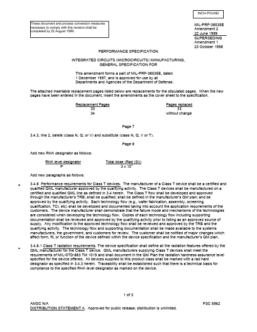
MIL-PRF-38535E Amendment 222 June 1999SUPERSEDING Amendment 123 October 1998PERFORMANCE SPECIFICATIONINTEGRATED CIRCUITS (MICROCIRCUITS) MANUFACTURING,GENERAL SPECIFICATION FOR This amendment forms a part of MIL-PRF-38535E, dated 1 December 1997, and is approved for use by allDepartments and Agencies of the Department of Defense.The attached insertable replacement pages listed below are replacements for the stipulated pages. When the new pages have been entered in the document, insert the amendments as the cover sheet to the specification.Replacement PagesPages replaced 33 3334without changePage 73.4.3, line 2, delete (class N, Q, or V) and substitute (class N, Q, V or T).Page 8Add new RHA designator as follows:RHA level designatorTotal dose (Rad (Si))P3 x 104Add new paragraphs as follows:3.4.8 Performance requirements for Class T devices. The manufacturer of a Class T device shall be a certified and qualified QML manufacturer approved by the qualifying activity. The Class T devices shall be manufactured on a certified and qualified QML line as defined in 3.4 herein. The Class T flow shall be developed and approved through the manufacturer’s TRB; shall be qualified; shall be defined in the manufacturer’s QM plan; and be approved by the qualifying activity. Each technology flow (e.g., wafer fabrication, assembly, screening,qualification, TCI, etc) shall be developed and documented taking into account the application requirements of the customers. The device manufacturer shall demonstrate that the failure mode and mechanisms of the technologies are considered when developing the technology flow. Copies of each technology flow including supportingdocumentation shall be reviewed and approved by the qualifying activity prior to listing as an approved source of supply. Any modification to the approved technology flow shall be reviewed and approved by the TRB and the qualifying activity. The technology flow and supporting documentation shall be made available to the systemsmanufacturers, the government, and customers for review. The customer shall be notified of major changes which affect form, fit, or function of the device defined within the device specification and the manufacturer’s QM plan.3.4.8.1 Class T radiation requirements. The device specification shall define all the radiation features offered by the QML manufacturer for the Class T device. QML manufacturers supplying Class T devices shall meet therequirements of MIL-STD-883 TM 1019 and shall document in the QM Plan the radiation hardness assurance level specified for the device offered. All devices supplied to this product class shall be marked with a rad harddesignator as specified in 3.4.3 herein. Traceability shall be established such that there is a technical basis for compliance to the specified RHA level designator as marked on the device.1 of 3INCH-POUND**These document and process conversion measures necessary to comply with this revision shall be completed by 22 August 1999.Page 93.6.2a, add “T” to list of Device class designators.3.6.2a, add “P” to list of RHA designators.Page 103.6.2.1, line 1, delete “Letters M, D, L, R, F, G, or H...” and substitute “Letters M, D, P, L, R, F, G, or H...”3.6.2.3, delete Example PIN “5962-XXXXXZZ(N, Q, V (B or S))YY” and substitute as follows:“5962-XXXXXZZ(N, Q, V, T (B or S))YY”Page 13Add new paragraph: 6.1.1 Class T. As the requirements for class level T are specified in the manufacturer’s Quality Management (QM) Plan for each technology, the user is cautioned to review the manufacturer's QM Plan to assure that the part being acquired meets the requirements/reliability of the system application.Page 18Add new paragraph: 6.2.31 Class T. Class T is a quality level whose requirements are defined by paragraph 3.4.8 herein and as documented on an SMD.Page 30A.3.4.1.3 Add new RHA designator as follows:RHA level designator Total dose (Rad (Si))P 3 x 10⁴Page 40A.3.6.2.2, line 1, delete “Letters M, D, L, R, F, G, or H...” and substitute “Letters M, D, P, L, R, F, G, or H...”Page 41A.3.6.2.7, delete “or H” 4 places under “Lead frame or terminal material and finish”.Page 65A.4.9.3.7, Add footnote 1/,1/ The self-audit shall include any activities performed by a subcontractor, and shall ensure fullcompliance by the subcontractor to this appendix and the device specification or drawing. Any deviations or questionable areas shall be brought to the attention of the qualifying activity.The margins of this amendment are marked with an asterisk to indicate where changes from the previous amendment were made. This was done as a convenience only and the Government assumes no liability whatsoever for any inaccuracies in these notations. Bidders and contractors are cautioned to evaluate the requirements of this document based on the entire content irrespective of the marginal notations and relationship to the last previous amendment.CONCLUDING MATERIALCustodians: Civil agency coordinating activity: Preparing activity: Army - CR DOT-FAA(RD-650) DLA - CCNavy - ECAir Force – 11NASA - NADLA - CCReview activities: (Project 5962-1857) Army - AR, MI, SMNavy - MC, TD, AS, CG, OS, SHAir Force - 19, 85, 99APPENDIX ATABLE A-I. Testing guidelines for changes identified as major.Major changes Testing, MIL-STD-883, test method 5005 (All electrical parametersin accordance with the device specification or drawing 1/)a. b. c. d.e. f. g. h. i. j. k.l.m. n. o. p.Doping material source concentrationProcess techniqueDiffusion profileDie structureMask changes affecting die size or activeelementWafer diameterFinal die thicknessPassivation/glassivationMetallization changesDie attach methodDie attach processBond processBond wire material/dimensionPackage or lid structurePackage or lid materialPackage or lid dimensionLead frame materialLead frame dimensionCavity dimensionSealing profileSealing materialFrame attachFrame cleaningImplementation of test methodsCritical documents (see A.4.8.1.3b)Fab moveAssembly moveGroup A and C-1 deltas (variables only when deltas are required)Group A and C-1 deltas (variables only when deltas are required)Group A and C-1 deltas (variables only when deltas are required)Variable group A, C-1 prior to shipment, and notify qualifyingactivity if new area is smaller/larger in applicable package thanpreviously qualified.Group A, C-1 prior to shipmentGroup D-3Group A, C-1 and glass integrity test if current density is over2 x 105Group A, C-1, and B-5D-3 and D-4D-3 and D-4B-5 and D-3B-5 and D-3D-1 (variables), D-3, D-4, D-8 (lid torque) (variables)D-3, D-4, D-5, D-6 (variables), and D-8 (lid torque) (variables)D-1 (variables), D-2, and D-8 (lid torque) (variables)See A.4.4.2.7D-1 (variables) and D-2B-5, D-2, D-6 (variables), and D-8 (lid torque) (variables)D-3, D-4, D-6 (variables), and D-8 (lid torque) (variables)D-3, D-4, D-6 (variables), and D-8 (lid torque) (variables)B-3, D-3, D-4, D-6 (variables), and D-7 (adhesion of lead finish)(variables)B-3, D-2, D-3, and D-7 (adhesion of lead finish)Notify qualifying activity (may involve test demonstration)Notify qualifying activity (may involve test demonstration)Group A and CGroup D per each package family (see A.3.1.3.30) prior to shipSupersedes page 33 of MIL-PRF-38535E, dated 1 December 1997.33APPENDIX ATABLE A-I. Testing guidelines for changes identified as major - Continued.Major changes Testing, MIL-STD-883, test method 5005 (All electrical parametersin accordance with the device specification or drawing 1/)q. r. s. t. u. v.Test facility moveScribe/die separationQualification/QCI proceduresPassivation for RHADiffusion profile for RHASinter/anneal for RHANotify qualifying activity5 SEM photographs of randomly selected die showing one fulledge of die front and backNotify qualifying activityGroup A, E, C-1, and glass integrity test if current density is over 2x 10⁵Group A, E, and C-1 deltas (variables only when deltas arerequired).Group A, E, C-1, and B-51/ This table is for class level B subgroups only. For class level S, use the equivalent class level S subgroups.The current density shall be calculated at the point(s) of maximum current density (i.e., greatest current (seeA.3.5.5a) per unit cross section) for the specific device type and schematic or configuration. Individual device calculations are not required when appropriate documented design rules or requirements have been used, which limit or control the current density in the resulting design.e a current value equal to the maximum continuous current (at full fanout for digitals or at maximumload for linears) or equal to the simple time-averaged current obtained at maximum rated frequency andduty cycle with maximum load, whichever results in the greater current value at the point(s) of maximum current density. This current value shall be determined at the maximum recommended supply voltage(s) and with the current assumed to be uniform over the entire conductor cross-sectional area.e the minimum allowed metal thickness in accordance with manufacturing specifications and controlsincluding appropriate allowance for thinning experienced in the metallization step. The thinning factorover a metallization step is not required unless the point of maximum current density is located at thestep.e the minimum actual design conductor widths (not mask widths) including appropriate allowance fornarrowing or undercutting experienced in metal etching.d.Areas of barrier metals, not intended by design to contribute to current carrying capacity, andnonconducting material shall not be included in the calculation of conductor cross section.Thick film conductors multichip substrates (metallization strips, bonding interfaces, etc.) shall be designated so that no properly fabricated conductor shall dissipate more than 4 watts/cm2 when carrying, maximum design current.A.3.5.5.1 Metallization thickness. For class level S microcircuits, the minimum metallization thickness shall be 8,000 C (800 nm) for single level metal and for the top level of multi-level metal, and 5,000 C (500 nm) for the lower level(s) of multi-level metal. In all cases, the current density requirements of A.3.5.5 shall also be satisfied.A.3.5.5.2 Internal wire size and material. For class level S microcircuits, the internal wire diameter shall be .001 inch minimum (0.03 mm) and the internal lead wire shall be of the same metal as the die metallization.A.3.5.5.3 Internal lead wires. Internal lead wires or other conductors which are not in thermal contact with a substrate along their entire length (such as wire or ribbon conductors) shall be designed to experience, at maximum rated current, a continuous current for direct current, or an RMS current (peak current divided by /2), for alternating or pulsed current, not to exceed the values established by the following relationship:Reprinted without change.34。
军用电子元器件的质量等级

电子元器件的质量等级汇总整理张增照目录1元器件质量保证有关标准21。
1规范31。
2标准32可靠性表征方式42.1元件的失效率等级42.2产品保证等级53元器件的质量认证64元器件的质量等级74.1用于元器件生产控制、选择和采购的质量等级74.2用于电子设备可靠性预计的质量等级94。
3元器件两种质量等级的比较95元器件的选用与质量标记175.1元器件的选用175。
2质量标记196结束语201元器件质量保证有关标准为了保证军用元器件的质量,我国制订了一系列的元器件标准。
在七十年代末期制订的“七专”7905技术协议和八十年代初期制订的“七专”8406技术条件(以下统称“七专”条件),“七专"技术条件是建立我国军用元器件标准的基础,目前按“七专”条件或其加严条件控制生产的元器件仍是航天等部门使用的主要品种。
(注:“七专”指专人、专机、专料、专批、专检、专技、专卡) 根据发展的趋势,“七专"条件将逐步向元器件的国家军用标准(GJB)过渡。
因此,以下将主要介绍元器件国家军用标准的有关情况。
从八十年代开始,我国军用标准化组织参照美国军用标准(MIL)体系建立了GJB体系,其中元器件的标准有规范、标准、指导性技术文件三种形式: a。
规范—主要包括:元器件的总规范和详细规范,这两种规范统称产品规范。
b。
标准—主要包括:试验和测量标准、质量保证大纲和生产线认证标准、元器件材料和零件标准、型号命名标准、文字和图形符号标准等;c. 指导性技术文件—主要包括:指导正确选择和使用元器件的指南、用于电子设备可靠性预计的手册、元器件系列型谱等。
根据我国的具体情况,军标分为国家军用标准、行业军用标准、企业军用标准三个级别。
下面对组成国家军用元器件标准体系的三种形式:规范、标准和指导性技术文件分别举例作简要的介绍。
1.1规范元器件规范主要包括:元器件的总规范(通用规范)和详细规范两个层次。
总规范对某一类元器件的质量控制规定了共性的要求,详细规范是对某一类元器件中的一个或一系列型号规定的具体的性能和质量控制要求,总规范必须与详细规范配套使用.元器件的产品规范是元器件生产线认证和元器件鉴定的依据之一,也是使用方选择、采购元器件的主要依据.现在我国国防工业主管部门已发布了大量的元器件总规范,但是详细规范还没完全配套,所以往往由器件生产单位制定了详细规范(属于企业军标准级别)经标准化机构确认后贯彻执行.已发布的军用元器件总规范中,影响较大的总规范及其参照采用的MIL标准如表1-1所示。
美军现行的电磁兼容标准

美军现行的电磁兼容标准
美国军方在使用电子设备时,必须遵循严格的电磁兼容标准。
这些标准旨在确保各种电子设备不会互相干扰,同时也要能够抵御外部干扰。
美军现行的电磁兼容标准包括MIL-STD-461和MIL-STD-464。
MIL-STD-461规定了电磁兼容性测试的要求和程序,以确保各种电子设备在安装和使用过程中都能够正常运行,并且不会对其他设备造成干扰。
MIL-STD-464则规定了电磁环境效应的要求和测试方法,以确保各种电子设备能够在各种电磁环境下正常工作。
这些环境包括雷电、电磁脉冲、辐射和电磁噪声等。
美军的电磁兼容标准不仅适用于军事设备,还适用于民用设备,以确保这些设备在军事基地和其他军事设施附近的环境中不会对军
事设备造成干扰。
此外,这些标准还适用于美军的合作伙伴和承包商,以确保他们提供的设备符合美军的要求。
- 1 -。
美军维修性标准改革取得重要进展
美军维修性标准改革取得重要进展
伍平洋
【期刊名称】《航天标准化》
【年(卷),期】1997(000)003
【摘要】美国国防标准改进委员会(DSIC)1996年决定废止MIL-STD-470B《系统和设备的维修性大纲》和MIL-STD-471A《维修性核查、验证和评价》两项标准,同时将两者合并编制符合最新的采办改革工作和政策要求、军民系统均适用的一项新手册。
1996年
【总页数】1页(P35-35)
【作者】伍平洋
【作者单位】七0八所
【正文语种】中文
【中图分类】F471.2
【相关文献】
1.美军机载『先进战术激光武器』取得重要进展 [J], 袁俊
2.AIM Global 汉信码标准取得重要进展——汉信码标准修订面对面会议报道 [J], 王毅
3.AIM GIobal汉信码标准取得重要进展——汉信码标准修订面对面会议报道 [J], 王毅
4.“标”出新规范--我国企业标准改革取得重要进展 [J], 《中国质量报》
5.国务院印发《关于全面振兴东北地区等老工业基地的若干意见》,明确到2020
年。
东北地区在重要领域和关键环节改革上取得重大成果。
转变经济发展方式和结构性改革取得重大进展,经济保持中高速增长。
与全国同步实现全面建成小康社会目标 [J],
因版权原因,仅展示原文概要,查看原文内容请购买。
美国波音(MS美国军标技术规范)
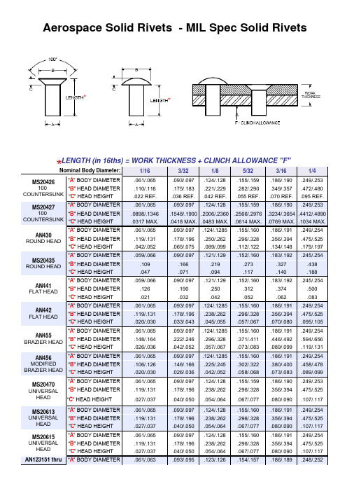
.067/.077
.080/.090
.107/.117
MS20615
UNIVERSAL HEAD
“A” BODY DIAMETER
.061/.065
.093/.097
.124/.128
.155/.160
.186/.191
.249/.254
“B” HEAD DIAMETER
.119/.131
3/8
.490/.640
.120/.250
This chart is a guide to help determine how much a solid rivet should be squeezed.
This is general information and may vary greatly depending upon the application.
“C” HEAD HEIGHT
.022 REF.
.036 REF.
.042 REF.
.055 REF.
.070 REF.
.095 REF.
MS20427
100° COUNTERSUNK
“A” BODY DIAMETER
.061/.065
.093/.097
.124/.128
.155/.159
.186/.190
.178/.196
.238/.262
.296/.328
.356/.394
.475/.525
“C” HEAD HEIGHT
.027/.037
.040/.050
.054/.064
.067/.077
.080/.090
.107/.117
- 1、下载文档前请自行甄别文档内容的完整性,平台不提供额外的编辑、内容补充、找答案等附加服务。
- 2、"仅部分预览"的文档,不可在线预览部分如存在完整性等问题,可反馈申请退款(可完整预览的文档不适用该条件!)。
- 3、如文档侵犯您的权益,请联系客服反馈,我们会尽快为您处理(人工客服工作时间:9:00-18:30)。
This document and process INCH-POUNDconversion measures necessary tocomply with this revision shall becompleted by 7 July 2003MIL-PRF-38534E6 January 2003SUPERSEDINGMIL-PRF-38534D6 January 1999PERFORMANCE SPECIFICATIONMICROCIRCUITS, HYBRIDGENERAL SPECIFICATION FORThis specification is approved for use by all Depart-ments and Agencies of the Department of Defense.This document is a performance specification. It is intended to provide the device manufacturers an acceptableestablished baseline in order to support Government microcircuit applications and logistic programs. The basicdocument has been structured as a performance specification that is supplemented with detailed appendices.These appendices provide guidance to manufacturers on demonstrated successful approaches to meeting military performance requirements. These appendices are included as a benchmark and are not intended to imposemandatory requirements.1. SCOPE1.1 Scope. This specification establishes the general performance requirements for hybrid microcircuits, Multi-*Chip Modules (MCM) and similar devices and the verification requirements for ensuring that these devices meet the applicable performance requirements. Verification is accomplished through the use of one of two quality programs (Appendix A). The main body of this specification describes the performance requirements and the requirements for obtaining a Qualified Manufacturers List (QML) listing. The appendices of this specification are intended forguidance to aid a manufacturer in developing their verification program. Detail requirements, specific characteristics, and other provisions that are sensitive to the particular intended use should be specified in the applicable deviceacquisition specification.Beneficial comments (recommendations, additions, deletions) and any pertinent data which may be of usein improving this document should be addressed to: Defense Supply Center Columbus (DSCC-VAS), PO Box3990, Columbus, OH 43216-5000, by using the Standardization Document Improvement Proposal (DD Form1426) appearing at the end of this document, or by letterAMSC N/A FSC 5962 DISTRIBUTION STATEMENT A. Approval for public release; distribution is unlimited.121.2 Description of this specification. The intent of this specification is to allow the device manufacturer the flexibility to implement best commercial practices to the maximum extent possible while still providing product which meets the military performance needs. Devices that are compliant to this specification are those that are capable of meeting the verification requirements outlined herein; and are built on a manufacturing line which is controlled by the manufacturer's quality management program and has been certified and qualified in accordance with the requirements herein. The certification and qualification requirements outlined herein are the requirements to be met by a manufacturer to be listed on the Qualified Manufacturers List (QML). The manufacturer may modify, substitute or delete the tests and inspections defined herein. This is accomplished by baselining a flow of tests and inspections that will assure that the devices are capable of meeting the generic verifications provided in this specification. This does not necessarily mean that compliant devices have been subjected to the generic performance verifications provided in this specification, just that compliant devices are capable of meeting them. It is the manufacturer's responsibility to ensure that their devices are capable of meeting the generic performance verifications applicable to each specified product assurance level. Appendix A defines the quality management program that may be implemented by the manufacturer. Appendix A includes an option to use a quality review board concept, hereafter referred to as the Technology Review Board (TRB) in this document, which may be used to modify the generic verification, design and construction criteria provided in this specification. Appendix B is not currently being used. Appendix C defines generic performance verifications. These verifications consist of a series of tests and inspections which may be used to verify the performance of devices. They may be used as is or modified as allowed by this specification. Appendix D is not currently being used. Appendix E defines generic design and construction criteria relative to this technology, including rework limitations and major change testing guidance. Appendix F provides statistical sampling procedures. Appendix G provides the guidelines for a Radiation Hardness Assurance (RHA) program. 1.3 Classification. Five quality assurance levels are provided for in this specification. Four of these classes, in highest to lowest order, are K, H, G, and D, as defined below. The fifth class is Class E, the quality level associated with a Class E device is defined by the acquisition document. 1.3.1 Class K. Class K is the highest reliability level provided for in this specification. It is intended for space applications. 1.3.2 Class H. Class H is the standard military quality level. 1.3.3 Class G. Class G is a lowered confidence version of the standard military quality level (H) with QML listing per 4.5.2.2, a possibly lower temperature range (-40o C to +85o C), a manufacturer guaranteed capability to meet the Class H Conformance Inspection and Periodic Inspection testing, and a vendor specified incoming test flow. The device must meet the Class H requirements for In-Process Inspections and Screening. 1.3.4 Class E. Class E designates devices which are based upon one of the other classes (K, H, or G) with exceptions taken to the requirements of that class. These exceptions are specified in the device acquisition document, therefore the device acquisition document should be carefully reviewed to ensure that the exceptions taken will not adversely affect the performance of the system. 1.3.5 Class D. Class D is a vendor specified quality level available to this specification. This is a possibly lower temperature range (0o C to +70o C) part with a vendor specified test flow available from a QML listed manufacturer. * * * **32. APPLICABLE DOCUMENTS 2.1 Government specifications, standards, and handbooks. The following specification and standard form a part of this document to the extent specified herein. Unless otherwise specified, the issue of these documents are those listed in the issue of the Department of Defense Index of Specifications and Standards (DODISS) and supplement thereto, cited in the solicitation (see 6.2).SPECIFICATIONDEPARTMENT OF DEFENSEMIL-I-46058 - Insulating Compound, Electrical (For Coating Printed Circuit Assemblies)STANDARDDEPARTMENT OF DEFENSEMIL-STD-883 - Test Methods and Procedures for Microelectronics(Unless otherwise specified copies of military standards are available from the Standardization Documents Order Desk, Building 4D, 700 Robbins Avenue, Philadelphia, PA 19111-5094. Copies of military standards are also available online from the Acquisition Streamlining and Standardization Information System (ASSIST) at /online/new/.2.2 Other Government documents, drawings, and publications. The following other Government documents, drawings, and publications form a part of this document to the extent specified herein. Unless otherwise specified, the issues are those cited in the solicitation.Handbook H4/H8 - Commercial and Government Entity (CAGE) Handbook.NAVSHIPS 0967-190-4010 - Manufacturer's Designating Symbols.QML-38534 - Qualified Manufacturer's List of Custom Hybrid Microcircuits QualifiedUnder Military Specification MIL-PRF-38534(Unless otherwise specified copies of military standards are available from the Standardization Documents Order Desk, Building 4D, 700 Robbins Avenue, Philadelphia, PA 19111-5094.)2.3 Order of Precedence. In the event of a conflict between the text of this document and the references cited herein (except for related associated detail specifications, specification sheets, or MS standards), the text of thisdocument takes precedence. Nothing in this document, however, supersedes applicable laws and regulations unless a specific exemption has been obtained.3. REQUIREMENTS3.1 Performance Requirements for Class K Devices. Class K devices shall be capable of meeting the Class K tests and inspections of Appendices C and E (see Table I). This shall include the incoming inspection flow, the in-process inspection flow, the screening flow, and the Conformance Inspection and Periodic Inspection flow. These devices shall be specified over the temperature range of -55o C to +125o C or as specified in the device acquisition document. Manufacturers of these devices shall be fully certified and qualified in accordance with this specification. Verification of these Performance Requirements shall be performed as described in paragraph4.3.2 Performance Requirements for Class H Devices. Class H devices shall be capable of meeting the Class H tests and inspections of Appendices C and E (see Table I). This shall include the incoming inspection flow, the in-process inspection flow, the screening flow, and the Conformance Inspection and Periodic Inspection flow. These devices shall be specified over the temperature range of -55o C to +125o C or as specified in the device acquisition document. Manufacturers of these devices shall be fully certified and qualified in accordance with this specification. Verification of these Performance Requirements shall be performed as described in paragraph4. **4 3.3 Performance requirements for Class G devices. Class G devices shall be capable of meeting the Class H tests and inspections of Appendices C and E, except incoming inspection (see Table I). This shall include the In-Process Inspection flow, the screening flow, and the Conformance Inspection and Periodic Inspection flow. Compliance with the Conformance Inspection and Periodic Inspection flow must be guaranteed by the manufacturer. Actual completion of Conformance Inspection and Periodic Inspection tests and inspections are optional and at the manufacturer's discretion. DSCC approval or notification is not required to eliminate Conformance Inspection and Periodic Inspection tests and inspections for this class of device, however it is the manufacturer's responsibility to ensure that their devices are capable of passing these tests and inspections. These devices shall be specified over the temperature range of -40o C to +85o C or a wider range. Manufacturers of these devices shall be fully certified and QML listed in accordance with this specification. Verification of these Performance Requirements shall be performed as described in paragraph 4. 3.4 Performance requirements for Class E devices. Class E devices are devices which meet all of the requirements of one of the other classes (K, H, or G) with some exceptions taken. The device acquisition document shall clearly state which class the device is based upon (K, H, or G) and what exceptions are being taken. The users of these devices should carefully examine the device acquisition document to verify that the exceptions being taken will not adversely affect the system performance. Manufacturers of these devices shall be fully certified in accordance with this specification. Verification of the performance requirements shall be performed as described in paragraph 4. 3.5 Performance requirements for Class D devices. Class D devices are built and tested in accordance with the manufacturer's specified production and testing flow (see Table I). These devices shall be capable of meeting the specified electrical tests. However, these devices are not required to meet any of the tests and inspections of this specification. These devices shall be specified over the temperature range of 0o C to +70o C or a wider range. Manufacturers of these devices shall be fully certified and QML listed in accordance with this specification. Verification of these Performance Requirements shall be performed as described in paragraph 4. 3.6 Performance requirements for RHA devices. Compliant RHA devices must meet the additional performancerequirements of Appendix G. Detailed information for producing and acquiring RHA devices can be found in JEDEC publication JEP133. * **5TABLE I. Performance Requirements Summary. Class Test Flow or Requirement 1/D E 2/ G 2/ H 2/ K 2/ CertificationRequired Required Required Required (Class H) Required (Class K) QML ListingRequired per 4.5.2.2 Required per 4.5.2.2 Required per 4.5.2.1 Required per 4.5.2.1 Incoming Inspection(App. C)Manufacturer Specified 3/ Manufacturer Specified 3/ Applicable (Class H) 1/ Applicable (Class K) 1/ In-ProcessInspections(App. C)Manufacturer Specified 3/ Applicable (Class H) 1/ Applicable 1/ Applicable 1/ Screening (App. C)Manufacturer Specified 3/ Applicable (Class H) 1/ Applicable (Class H) 1/ Applicable (Class K) 1/ ConformanceInspection andPeriodic Inspection(App. C)Manufacturer Specified 3/ Guaranteed (Class H) 4/ Applicable (Class H) 1/ Applicable (Class K) 1/ Temperature Range 5/ 0o C to +70o C Required per the Applicable device class and the Acquisition Document -40o C to +85o C -55o C to +125o C -55o C to +125o C1/ For test flow implementation and available flexibility see 3.7.1. 2/ Design and construction and rework criteria are as specified in Appendix E and shall be utilized per 3.7.1. 3/ Manufacturer Specified means that the manufacturer does not have to take the generic criteria of this specification into consideration during the establishment of its manufacturing and test flows. The manufacturer's flow may or may not meet the same requirements as the flow of this specification. Furthermore, the manufacturer may specify that they do not perform the particular test or inspection flow. 4/ Guaranteed (Class H) means that the manufacturer is assuring that their devices will meet the Conformance Inspection and Periodic Inspection test flow contained in Tables C-Xa, C-Xb, C-Xc, and C-Xd, but may or may not actually perform the tests and inspections specified. Elimination of these tests and inspections does not necessitate DSCC approval or notification. 5/ Wider temperature ranges are also acceptable for classes D and G. Class H and K shall be -55o C to +125o C unless otherwise specified in the acquisition document.3.7 General. The manufacturer of devices, in compliance with this specification, shall have and use production and test facilities and a verification program adequate to assure successful compliance with the provisions of thisspecification and the associated device acquisition specification. Adequacy of a device manufacturer to meet the requirements of this specification shall be determined by the Government qualifying activity. The individual item requirements shall be as specified in the associated device acquisition specification and herein. Only devices which meet all the performance requirements of this specification and the associated device acquisition specification and have been adequately verified shall be marked as compliant and delivered. Monolithic microcircuits may be built to the Class K, H, G, E, or D performance requirements of this specification, however, monolithic microcircuits offered in compliance with this specification shall be specified on a Standard Microcircuit Drawing (SMD). Facilities andprograms listed on the Qualified Manufacturer's List (QML) may be used for the manufacture of other than compliant devices; however, any use or reference to compliant device marking, Class K, H, G, E, or D certification status or this specification in such a way as to state or imply equivalency (and thereby Government endorsement) in connection with noncompliant devices is prohibited and may be cause for revocation of certification or QML status (or both). Terms, definitions, methods, and symbols are per 6.3. Any military specification or standard referred to in this specification may be replaced by an equivalent commercial standard as determined by the preparing activity.**63.7.1 Implementation of this specification. All devices offered and shipped in compliance with this specification shall meet the performance requirements specified for the applicable device class. The manufacturer shall verify that devices meet the performance requirements of the applicable device class. The manufacturer is responsible for developing a verification program which will meet this requirement. The appendices of this specification give standard methods for verifying that the devices meet the performance requirements (except for Class D). The manufacturer may address the requirements of this specification as written, adapt them to their products, or develop a new methodology. Prior to the manufacturer being certified the actual verification program to be used shall be reviewed and approved by DSCC. Any deletions or changes to the test flow shall also be reviewed and approved by DSCC or the manufacturer's DSCC approved TRB prior to implementation. In this manner a manufacturer may use an alternative method to the method specified in this specification to evaluate their parts if the alternate method verifies the same performance requirement. Furthermore, the manufacturer may eliminate a test or inspection (or decrease the occurrence or sample size of the test or inspection) if it is shown that the test or inspection is not necessary or can be performed less frequently. It is the manufacturer's responsibility to show how their verification program (and any changes to it) meets the requirements of this specification. The manufacturer shall analyze the impact of major changes and their effect on previously approve modifications of test (test optimization). See Table II for clarification. TABLE II. Implementation Summary. Option Definition Typical Examples Implementation Procedures Meet requirement as written The manufacturer performs the test or requirement as specified Self explanatory The manufacturer implements the test or requirement into internal documentation, verified during certification For TRB companies, alternate method and appropriate justification are approved by the manufacturer's TRB. Alternate method to the requirement The manufacturer assures that the intent of the requirement is met, but does not perform the Test/requirement exactly as written - Replacement of a test with SPC or alternate method - Historical data analysis shows that the requirement is met -Design verification/validation shows that the process is capable of meeting the requirement - Requirement does not address new materials, technologies, designs For traditional companies, manufacturer proposes the alternate method and justification to the Qualifying Activity for approval. The manufacturer proves that the test or requirement is either: Non-value added - Test does not stress the process adequately (e.g., PIND for encapsulated parts) - Historical data analysis shows that the test does not induce failures Elimination is achieved in the same manner as alternate methods described above The product will not comply with the test or requirement due to technology limitations - configuration of the product (i.e., size, mass, package, etc.) is incompatible with the test method The exception shall be documented in the applicable acquisition document. Product is classified as Class E Elimination of the requirement Application has no need of the requirementThe device will not experience theparticular stress in the application The exception shall be documented in the applicable acquisition document. Productis classified as Class E3.7.2 Device acquisition specification. The preferred device acquisition document for devices built in full compliance with this specification is a Standard Microcircuit Drawing (SMD). Monolithic microcircuits built in compliance with this document shall be documented on an approved SMD.**3.7.3 Design and Construction. The design and construction of compliant devices shall address the limitations and guidelines of Appendix E.3.7.3.1 Lead finish. Appendix E provides the general interface requirements for lead finishes.3.7.4 Workmanship. Devices shall be manufactured, processed, and verified to meet the performance requirements of this specification, and with the production practices, workmanship instructions, inspection and test procedures, and training aids prepared by the manufacturer in fulfillment of the Baseline Process Flow.3.7.4.1 Rework and repair provisions. All rework and repair operations shall address the limitations and guidelines of Appendix E.3.7.5 Marking of devices. Marking shall be in accordance with the requirements of this specification or the device procurement specification. The marking shall be legible and complete, and shall meet the resistance to solvents requirements of MIL-STD-883, method 2015. When mechanical or laser marking is performed it shall be clearly visible through those conformal coatings approved for use in MIL-I-46058 (see method 2015 of MIL-STD-883 if contrasting material or ink is used to highlight the trace). Mechanical or laser marked metal surfaces shall meet all applicable microcircuit finishes and shall not degrade the performance requirements of the device. Mechanical or laser marking shall be approved by the qualifying activity. If any special marking is used, it shall in no way interfere with the marking required herein, and shall be visibly separated therefrom. The following marking shall be included on each microcircuit unless otherwise specified.a. Part or Identifying Number (PIN) (see 3.7.5.1).b. Index point (see 3.7.5.2).c. Lot identification code or date code (see 3.7.5.3).d. Device manufacturer's identification (see 3.7.5.4).e. Device manufacturer's designating symbol (see 3.7.5.5).f. Country of manufacture (see 3.7.5.6).g. Serialization, when applicable (see 3.7.5.7).h. Special marking (see 3.7.5.8).i. ESD sensitivity identifier (see 3.7.5.8.2).j. Certification mark (see 3.7.5.8.3).Unless otherwise specified, the certification mark, the PIN, the inspection lot identification code, and the ESD identifier shall be located on the top surface of flat packages or dual-in-line configurations and on either the top or the side of cylindrical packages (TO configurations and similar configurations).3.7.5.1 Part or Identifying Number (PIN). Each Standard Microcircuit Drawing (SMD) microcircuit shall be marked with the complete PIN, as specified in the SMD. The number sequence for MIL-PRF-38534 is 5962-XXXXXZZHYY, where:5962 - XXXXX ZZ H Y YFederal RHA Device QML Case Leadstock class designator type no. device outline finishdesignator (see 3.7.5.1.1) class (see 3.7.5.1.3) designator\ / designator (see 3.7.5.1.4)\/ (see 3.7.5.1.2)Drawing number73.7.5.1.1 Device type. The device type shall identify the circuit function as indicated in the SMD.3.7.5.1.2 Device class designator. This device class designator shall be a single letter identifying the quality level in accordance with the SMD.3.7.5.1.3 Case outline. The case outline shall be designated by a single letter assigned to each outline within each SMD.3.7.5.1.4 Lead finish. Lead frame or terminal material and finish shall be as specified (see Appendix E). The lead finish shall be designated by a single letter as follows:Finish letter Lead finish (see note)A hot solder dipB tin-lead plateC gold plateX finishes A, B, or C (see note)NOTE: Finish letter "X" shall not be marked on the microcircuit or its packaging. This designation is provided for use in drawings, part lists, purchase orders, or other documentation where lead finishes A, B, andC are all considered acceptable and interchangeable without preference. For Government logisticsupport, the A lead finish will be acquired and supplied to the end user when the X is included in thePIN for lead finish. If the PIN is not available with the A lead finish, the same PIN will be acquiredexcept with the C or B lead finish designator as determined by availability. Type C terminal material isa fired on metallization used with leadless chip carriers.3.7.5.2 Index point. The index point, tab, or other marking indicating the starting point for numbering of leads or for mechanical orientation shall be as specified and shall be applied so that it is visible from above when the microcircuit is installed in its normal mounting configuration. The outline of an equilateral triangle (i.e., ∆), which may be used as an electrostatic identifier (see 3.7.5.8.2), may also be used as the pin 1 identifier.3.7.5.3 Lot identification code (date code). Devices shall be marked by a unique code to identify the week of final seal. The first two numbers in the code shall be the last two digits of the number of the year, the third and fourth numbers shall be two digits indicating the calendar week of the year. When the number of the week is a single digit, it shall be preceded by a zero. Reading from left to right or from top to bottom, the code number shall designate the year and week, in that order (e.g., 8806 equals week 6 of 1988).3.7.5.4 Manufacturer's identification. Devices shall be marked with the name or trade mark of the manufacturer. The identification of the equipment manufacturer may appear on the device only if the equipment manufacturer is also the device manufacturer.3.7.5.5 Manufacturer's designating symbol. When space permits, the manufacturer may mark the CAGE code on devices. The manufacturer's designating symbol or CAGE code number shall be as listed on NAVSHIPS0967-190-4010 or cataloging Handbook H4/H8. The designating symbol shall be used only by the manufacturer to whom it has been assigned and only on those devices manufactured at the manufacturer's plant. In the case of small devices, the manufacturer's designating symbol may be abbreviated by omitting the first "C" in the series of letters.3.7.5.6 Country of manufacture. The manufacturer shall indicate the country where the device was manufactured(i.e., substrate and element attach, interconnect, seal). At the option of the manufacturer the country of manufacture marking may be omitted from the body of the device but shall be retained on the initial container.3.7.5.7 Serialization. Serialization allows traceability of electrical tests results (variables data) to an individual device.3.7.5.7.1 Class K serialization. Prior to the first recorded electrical measurement in screening, each Class K device shall be marked with a unique serial number assigned consecutively. Lot records shall be maintained to provide traceability from the serial number to the specific incoming inspection lots from which the elements originated.83.7.5.7.2 Class H, G, and D serialization. Serialization of Class H, G, and D devices shall only be required whenspecified in the device acquisition specification.3.7.5.8 Special marking. When the size of a package is insufficient to allow marking of special process identifierson the top surface, the back side of the package may be used for these markings except the ESD identifier shall be marked on the top. Button cap flat packs with less than or equal to 16 leads may have the identifier marked on the ceramic. Back side marking with conductive or resistive ink shall be prohibited on nonconductive surfaces.3.7.5.8.1 Beryllium oxide package identifier. If a device package contains beryllium oxide, the device shall bemarked with this designation: BeO.NOTE: Packages containing beryllia will not be ground, sandblasted, machined, or have other operations performed on them which will produce beryllia or beryllium dust. Furthermore, beryllium oxidepackages will not be placed in acids that will produce fumes containing beryllium.3.7.5.8.2 Electrostatic discharge (ESD) sensitivity identifier. ESD classification levels are defined as follows whentested in accordance with MIL-STD-883, method 3015.PriorESD class designation Part Electrostaticdesignator category marking voltage1 A ∆ 0-1,999 V2 B ∆∆ 2,000-3,999 V*3 --- --- ≥ 4,000 VESD class marking is not required. However at the manufacturers option devices not yet ESD classified may be marked as class 1 until testing determines the appropriate class. Devices previously classed by test as category A may be marked as class 1. Devices previously classified as category B may be marked as class 2.3.7.5.8.3 Certification mark. All devices acquired to and meeting the requirements of this specification and theapplicable associated device acquisition specification, and which are approved for listing on QML-38534 shall bear a certification mark as shown in Table III.Table III. Certification Mark.Acquisition document Class Certification MarkSMD All QML or Q for small devicesK CKNon-SMD dated after this documentH CHG CGE CED CDNon-SMD dated prior to this document All CH or C for small devicesThese certification marks or the abbreviations "Q" or "C" shall not be used for any device acquired under contracts or orders which permit or require any changes to this specification except as allowed in 3.7.1. In the event that a lot fails to pass inspection, the manufacturer shall remove or obliterate the certification mark from the sample tested and also from the devices represented by the sample.3.7.5.9 Marking option for controlled storage of Class H and G. Where devices are subjected to testing andscreening in accordance with some portion of the quality assurance requirements and stored in controlled storage areas pending receipt of orders requiring conformance to the same or a different level, the inspection lot identification code shall be placed on the device package along with the other markings specified in 3.7.5 sufficient to assureidentification of the material. As an alternative, if the microcircuits are stored together with sufficient data to assure traceability to processing and inspection records, all markings may be applied after completion of all inspection to the specified level.9。